

Page 1
DESKTOP AUDIO SYSTEM
TSX-130/TSX-120
SERVICE MANUAL
For U, T, K, G, L, V and J models
This service manual is for the TSX-130/TSX-120 (U, T, K, G, L, V and J models).
For service manual of the TSX-130/TSX-120 (A and B models), please refer to the following publication number:
TSX-130/TSX-120 (A and B models): 101135
IMPORTANT NOTICE
This manual has been provided for the use of authorized YAMAHA Retailers and their service personnel.
It has been assumed that basic service procedures inherent to the industry, and more specifi cally YAMAHA Products, are already known
and understood by the users, and have therefore not been restated.
WARNING:
IMPORTANT:
The data provided is believed to be accurate and applicable to the unit(s) indicated on the cover. The research, engineering, and service
departments of YAMAHA are continually striving to improve YAMAHA products. Modifications are, therefore, inevitable and
specifi cations are subject to change without notice or obligation to retrofi t. Should any discrepancy appear to exist, please contact the
distributor's Service Division.
WARNING:
IMPORTANT:
Failure to follow appropriate service and safety procedures when servicing this product may result in personal injury,
destruction of expensive components, and failure of the product to perform as specifi ed. For these reasons, we advise
all YAMAHA product owners that any service required should be performed by an authorized YAMAHA Retailer or
the appointed service representative.
The presentation or sale of this manual to any individual or fi rm does not constitute authorization, certifi cation or
recognition of any applicable technical capabilities, or establish a principle-agent relationship of any form.
Static discharges can destroy expensive components. Discharge any static electricity your body may have
accumulated by grounding yourself to the ground buss in the unit (heavy gauge black wires connect to this buss).
Turn the unit OFF during disassembly and part replacement. Recheck all work before you apply power to the unit.
■ CONTENTS
TO SERVICE PERSONNEL ........................................2–4
PREVENTION OF ELECTROSTATIC DISCHARGE ......5
FRONT PANELS ......................................................... 6–7
REAR PANELS .........................................................8–10
REMOTE CONTROL PANELS ..................................... 11
SPECIFICATIONS /
INTERNAL VIEW .......................................................... 13
DISASSEMBLY PROCEDURES /
UPDATING FIRMWARE /
ファームウェアの書き込み
SELF-DIAGNOSTIC FUNCTION /
ダイアグ(自己診断機能)
参考仕様
.......................................12
分解手順
.....................................18–23
.......................................24–38
........... 14–17
DISPLAY DATA .......................................................39–40
IC DATA ...................................................................41–44
PIN CONNECTION DIAGRAMS .............................45–46
BLOCK DIAGRAM ........................................................ 47
PRINTED CIRCUIT BOARDS .................................48–57
SCHEMATIC DIAGRAMS ....................................... 59–62
REPLACEMENT PARTS LIST ................................ 63–83
REMOTE CONTROL .....................................................84
ADJUSTING THE CLOCK /
時計を合わせる
TSX-130/TSX-120
................85
101124
Copyright © 2008 All rights reserved.
This manual is copyrighted by YAMAHA and may not be copied or
redistributed either in print or electronically without permission.
P.O.Box 1, Hamamatsu, Japan
animate '08.12
Page 2
TSX-130/TSX-120
TSX-130/TSX-120
■ TO SERVICE PERSONNEL
1. Critical Components Information
Components having special characteristics are marked ⚠ and
must be replaced with parts having specifications equal to those
originally installed.
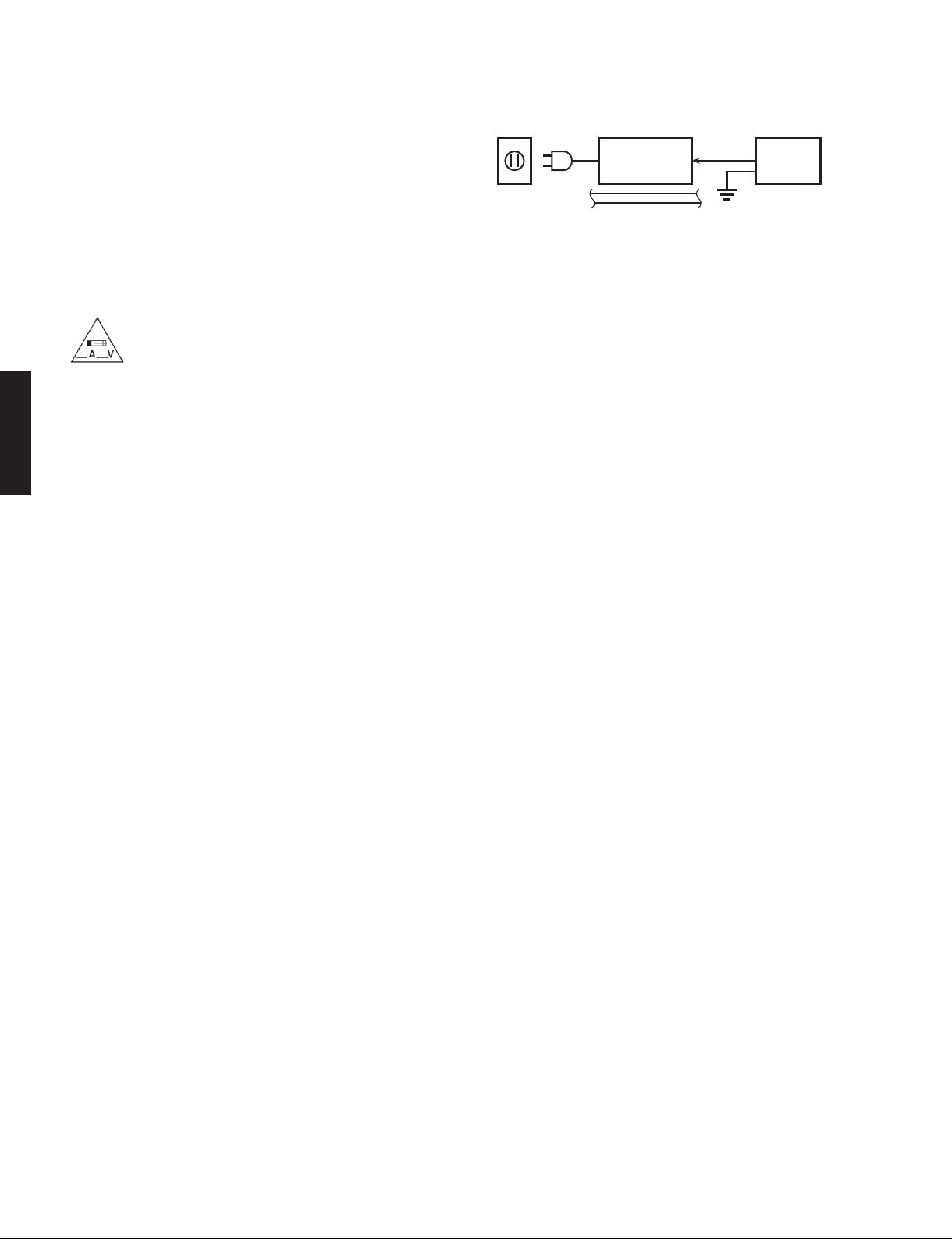
2. Leakage Current Measurement (For 120V Models Only)
When service has been completed, it is imperative to verify
that all exposed conductive surfaces are properly insulated
from supply circuits.
• Meter impedance should be equivalent to 1500 ohms shunted
by 0.15 μF.
For U model
“CAUTION”
“F1: FOR CONTINUED PROTECTION AGAINST RISK OF FIRE, REPLACE ONLY WITH SAME TYPE 1A, 125V
FUSE.”
For C model
CAUTION
F1: REPLACE WITH SAME TYPE 1A, 125V FUSE.
ATTENTION
F1: UTILISER UN FUSIBLE DE RECHANGE DE MÉME TYPE DE 1A, 125V.
WALL
OUTLET
• Leakage current must not exceed 0.5mA.
• Be sure to test for leakage with the AC plug in both polarities.
EQUIPMENT
UNDER TEST
INSULATING
TABLE
AC LEAKAGE
TESTER OR
EQUIVALENT
WARNING: CHEMICAL CONTENT NOTICE!
This product contains chemicals known to the State of California to cause cancer, or birth defects or other reproductive
harm.
DO NOT PLACE SOLDER, ELECTRICAL/ELECTRONIC OR PLASTIC COMPONENTS IN YOUR MOUTH FOR ANY REASON
WHATSOEVER!
Avoid prolonged, unprotected contact between solder and your skin! When soldering, do not inhale solder fumes or
expose eyes to solder/flux vapor!
If you come in contact with solder or components located inside the enclosure of this product, wash your hands before
handling food.
About lead free solder /
All of the P.C.B.s installed in this unit and solder joints are
soldered using the lead free solder.
Among some types of lead free solder currently available,
it is recommended to use one of the following types for
the repair work.
• Sn + Ag + Cu (tin + silver + copper)
• Sn + Cu (tin + copper)
• Sn + Zn + Bi (tin + zinc + bismuth)
Caution:
As the melting point temperature of the lead free solder
is about 30°C to 40°C (50°F to 70°F) higher than that of
the lead solder, be sure to use a soldering iron suitable
to each solder.
無鉛ハンダについて
本機に搭載されているすべての基板およびハンダ付けに
よる接合部は無鉛ハンダでハンダ付けされています。
無鉛ハンダにはいくつかの種類がありますが、修理時に
は下記のような無鉛ハンダの使用を推奨します。
Sn+Ag+Cu(錫+銀+銅)
Sn+Cu(錫 + 銅)
Sn+Zn+Bi(錫 + 亜鉛 + ビスマス)
注意:
無鉛ハンダの融点温度は通常の鉛入りハンダに比べ 30 〜
40℃程度高くなっていますので、それぞれのハンダに合っ
たハンダごてをご使用ください。
2
Page 3

WARNING: Lithium batteries
CAUTION
Danger of explosion if battery is incorrectly replaced.
Replace only with the same or equivalent type.
TSX-130/TSX-120
注意
正しい電池と交換しないと爆発が起きるおそれがありま
す。
同一型名または同等品以外の電池とは絶対に交換しない
ようにしてください。
WARNING:
they can be exploded by improper handling. Observe the
following precautions when handling or replacing lithium
batteries.
• Leave lithium battery replacement to qualified service
personnel.
• Always replace with batteries of the same type.
• When installing on the PC board by soldering, solder
using the connection terminals provided on the battery
cells. Never solder directly to the cells. Perform the
soldering as quickly as possible.
• Never reverse the battery polarities when installing.
• Do not short the batteries.
• Do not attempt to recharge these batteries.
• Do not disassemble the batteries.
• Never heat batteries or throw them into fire.
Lithium batteries are dangerous because
ADVARSEL!
Lithiumbatteri –Eksplosionsfare ved fejlagtig håndtering.
Udskiftning må kun ske med batteri af samme fabrikat og
type. Levér det brugte batteri tilbage til leverandøren.
VARNING
Explosionsfara vid felaktigt batteribyte. Använd samma
batterityp eller an ekvivalent typ som rekommenderas av
apparattillverkaren. Kassera använt batteri enligt fabrikantens instruktion.
VAROITUS
Paristo voi räjähtää, jos se on virheellisesti asennettu.
Vaihda paristo ainoastaan laitevalmistajan suosittelemaan
tyyppiin. Hävitä käytetty peristo valmistajan ohjeiden mukaisesti.
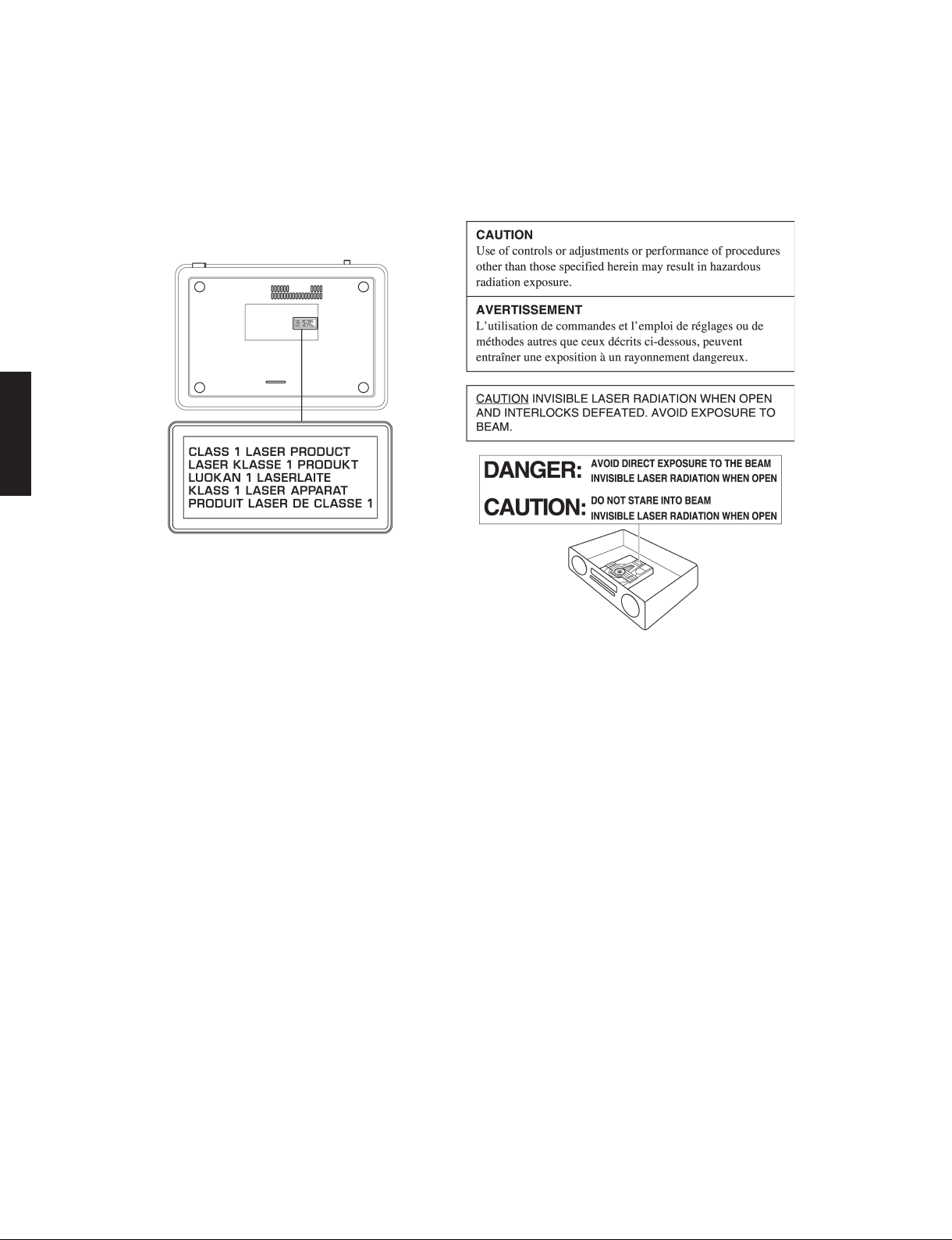
WARNING: Laser Safety
This product contains a laser beam component. This component may emit invisible, as well as visible radiation,
which may cause eye damage. To protect your eyes and skin from laser radiation, the following precautions must
be used during servicing of the unit.
1) When testing and/or repairing any component within the product, keep your eyes and skin more than 30 cm/1 feet
away from the laser pick-up unit at all times. Do not stare at the laser beam at any time.
2) Do not attempt to readjust, disassemble or repair the laser pick-up, unless noted elsewhere in this manual.
3) CAUTION: Use of controls, adjustments or performance of procedures other than those specified herein may result in
hazardous radiation exposure.
TSX-130/TSX-120
Laser Emitting conditions:
1) When the Top Cover is removed, and the STANDBY/ON SW is turned to the “ON” position, the laser component will
emit a beam for several seconds to detect if a disc is present. During this time (5-10 sec.) the laser may radiate
through the lens of the laser pick-up unit. Do not attempt any servicing during this period!
If no disc is detected, the laser will stop emitting the beam. When a disc is loaded, you will not be exposed to any
laser emissions.
2) The laser power level can be adjusted with the VR on the pick-up PWB, however, this level has been set by the factory
prior to shipping from the factory. Do not adjust this laser level control unless instruction is provided elsewhere in this
manual. Adjustment of this control can increase the laser emission level from the device.
3
Page 4
TSX-130/TSX-120
Laser Diode Properties
Type: Semiconductor laser GaAS/GaAlAs
Wave length: 780 nm
TSX-130/TSX-120
Output Power: 10 mW
Beam divergence: 60 degrees
Warning for power supply
The primary side of the power supply carries live mains voltage when the player is connected to the mains even
when the player is switched off !
This primary area is not shielded so it is possible to accidentally touch copper tracks and/or components when servicing
the player.
Service personnel have to take precautions to prevent touching this area or components in this area.
Note:
The screws on the DVD mechanism may never be touched, removed or re-adjusted.
Handle the DVD mechanism with care when the unit has to be exchanged!
The DVD mechanism is very sensitive for dropping or giving shocks.
4
Page 5
TSX-130/TSX-120
■ PREVENTION OF ELECTROSTATIC DISCHARGE
Some semiconductor (solid state) devices can be damaged easily by static electricity. Such components commonly are
called Electrostatically Sensitive (ES) Devices. Examples of typical ES devices are integrated circuits and some field-effect
transistors and semiconductor “chip” components. The following techniques should be used to help reduce the incidence
of component damage caused by electro static discharge (ESD).
1. Immediately before handling any semiconductor component or semiconductor-equipped assembly, drain off any ESD
on your body by touching a known earth ground. Alternatively, obtain and wear a commercially available discharging
ESD wrist strap, which should be removed for potential shock reasons prior to applying power to the unit under test.
2. After removing an electrical assembly equipped with ES devices, place the assembly on a conductive surface such as
aluminum foil, to prevent electrostatic charge buildup or exposure of the assembly.
3. Use only a grounded-tip soldering iron to solder or unsolder ES devices.
4. Use only an anti-static solder removal device. Some solder removal devices not classified as “anti-static (ESD protect-
ed)” can generate electrical charge sufficient to damage ES devices.
5. Do not use freon-propelled chemicals. These can generate electrical charges sufficient to damage ES devices.
6. Do not remove a replacement ES device from its protective package until immediately before you are ready to install it.
(Most replacement ES devices are packaged with leads electrically shorted together by conductive foam, aluminum foil
or comparable conductive material).
7. Immediately before removing the protective material from the leads of a replacement ES device, touch the protective
material to the chassis or circuit assembly into which the device will be installed.
CAUTION: Be sure no power is applied to the chassis or circuit, and observe all other safety precautions.
8. Minimize bodily motions when handling unpackaged replacement ES devices. (Otherwise harmless motion such as
brushing together of your fabric clothes or lifting of your foot from a carpeted floor can generate static electricity (ESD)
sufficient to damage an ES device).
TSX-130/TSX-120
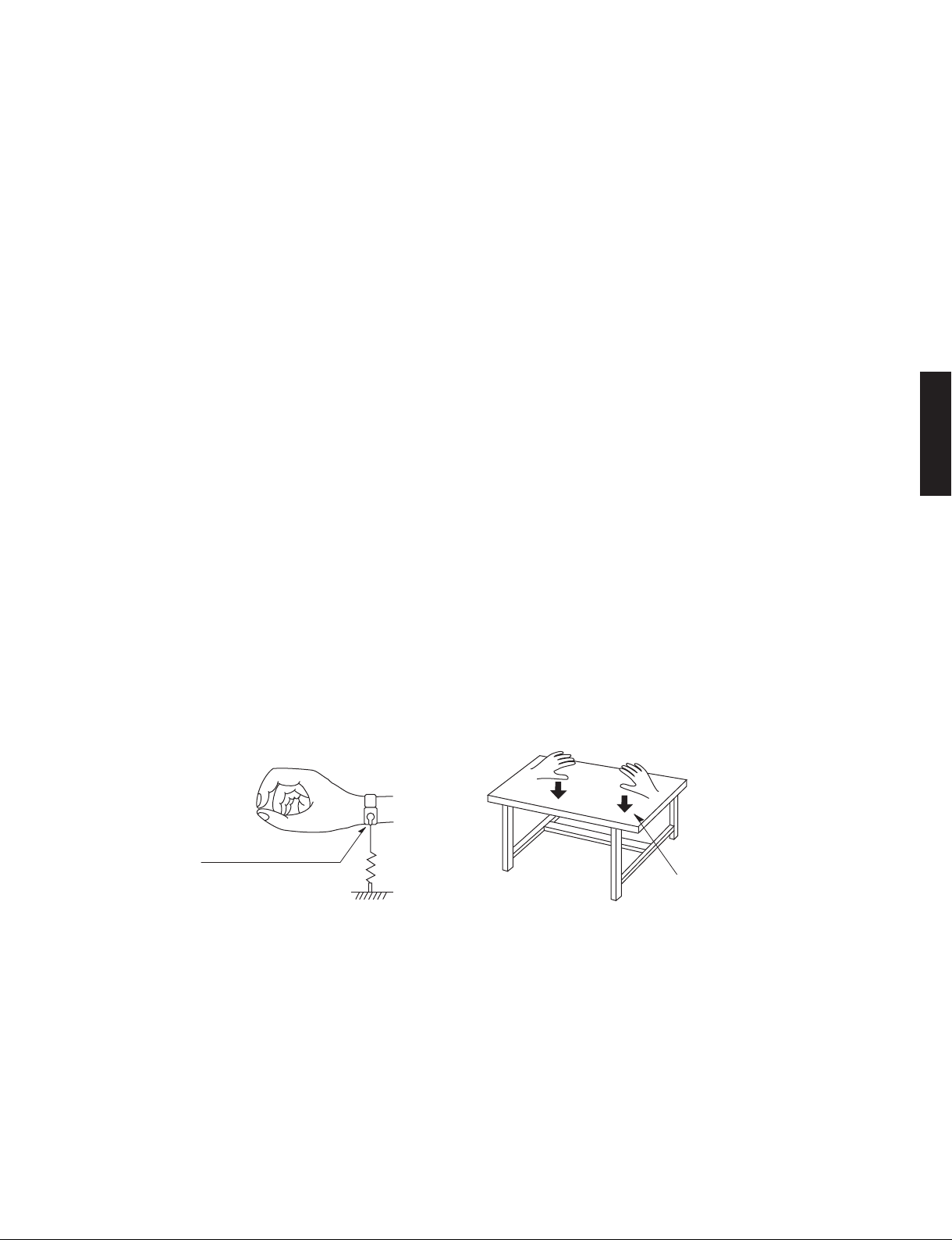
Grounding for electrostatic breakdown prevention
1. Human body grounding.
Use the antistatic wrist strap to discharge the static electricity from your body.
2. Work table grounding.
Put a conductive material (sheet) or steel sheet on the area where the optical pickup is placed and ground the sheet.
Caution:
The static electricity of your clothes will not be grounded through the wrist strap. So take care not to let your clothes touch
the optical pickup.
Anti-static wrist strap
1M-ohms
Conductive material
(sheet) or steel sheet
5
Page 6
TSX-130/TSX-120
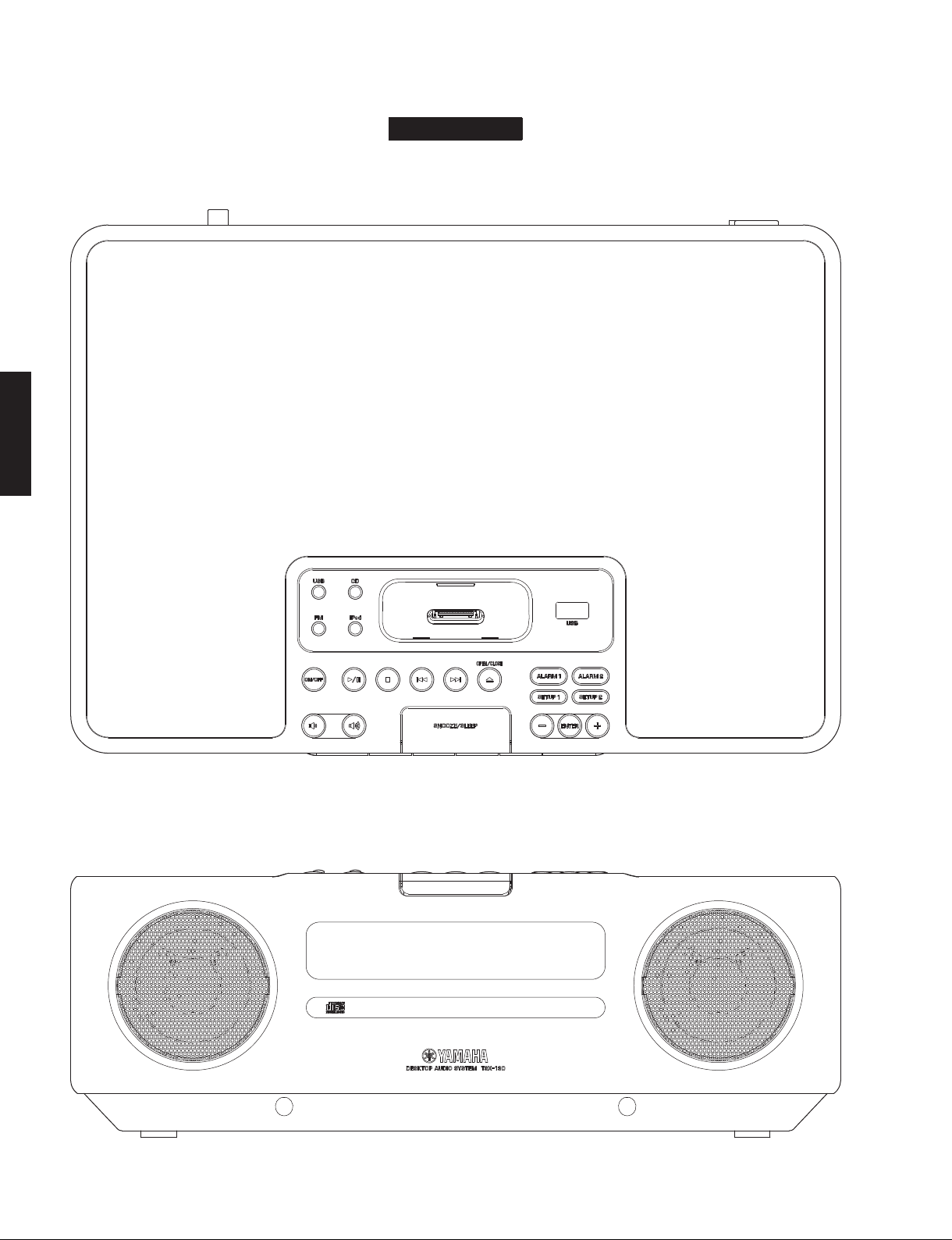
■ FRONT PANELS
Top view
TSX-130/TSX-120
TSX-130
Front view
6
Page 7
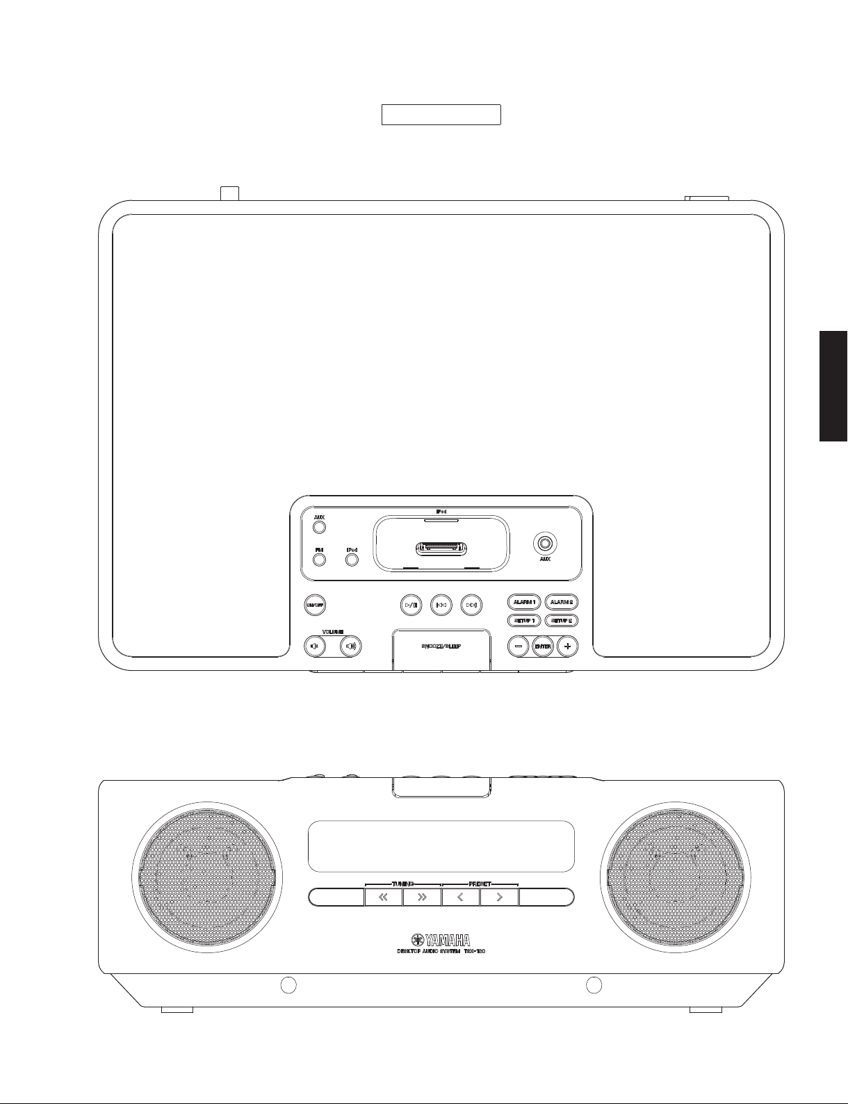
Top view
TSX-130/TSX-120
TSX-120
TSX-130/TSX-120
Front view
7
Page 8
TSX-130/TSX-120
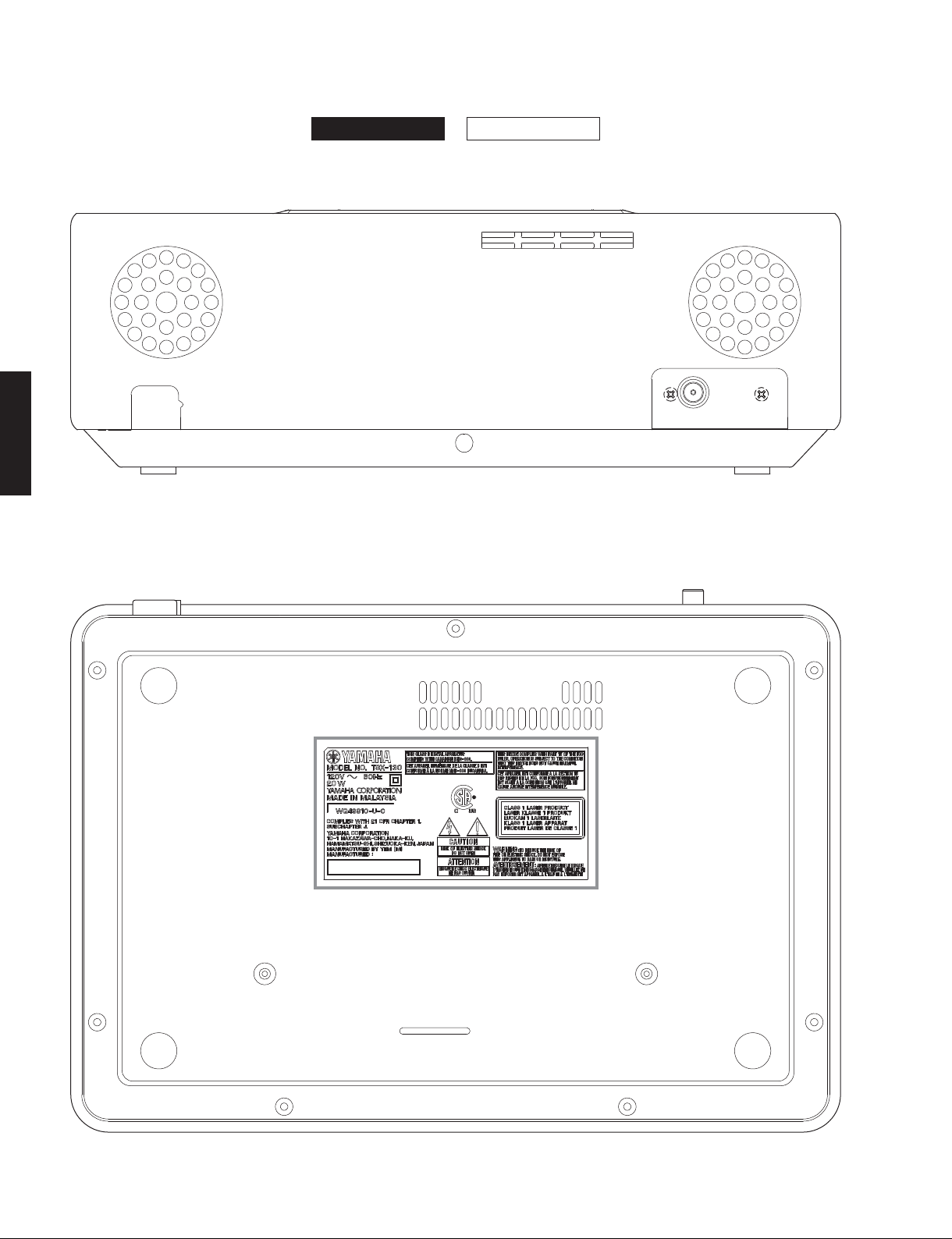
■ REAR PANELS
Rear view
TSX-130/TSX-120
TSX-130 TSX-120
Bottom view
Label
8
Page 9
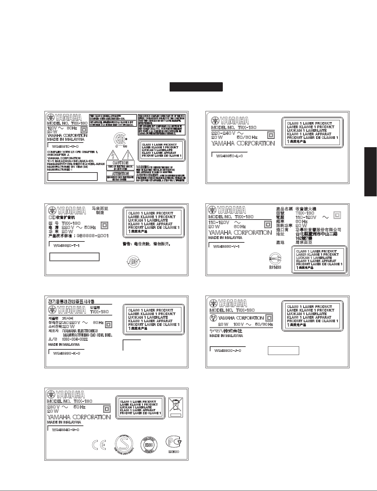
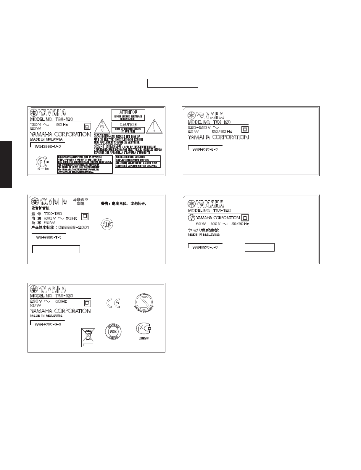
Labels
TSX-130
U model L model
TSX-130/TSX-120
TSX-130/TSX-120
T model V model
K model J model
G model
9
Page 10
TSX-130/TSX-120
TSX-120
U model L model
TSX-130/TSX-120
T model J model
G model
10
Page 11
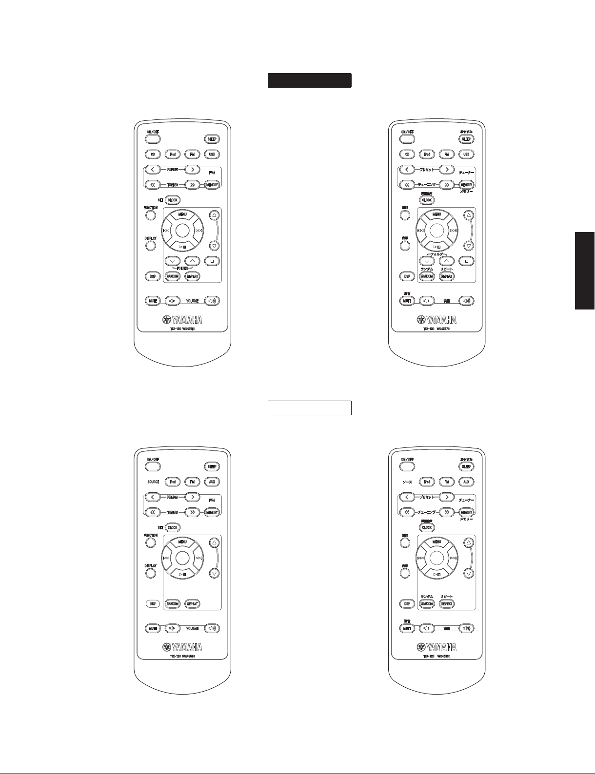
■ REMOTE CONTROL PANELS
TSX-130/TSX-120
TSX-130
U, T, K, G, L, V models
J model
TSX-130/TSX-120
U, T, G, L models
TSX-120
J model
11
Page 12
TSX-130/TSX-120
TSX-130/TSX-120
■ SPECIFICATIONS /
■ Player Section /
iPod: Supported iPod /
TSX-130
CD: Media /
USB: Audio format /
TSX-120
AUX IN: Input connector /
■ Amplifier / Speaker Section /
Minimum RMS output power per channel /
(6 ohms, 1 kHz, 10 % THD) ..........................................15 W + 15 W
Driver ......................................................8 cm (3-3/16") full-range x 2
Frequency Response /
■ FM Section /
Preset Memory /
Tuning Range /
U model ...............................................................87.5 to 107.9 MHz
T, K, G, L, V models .............................................87.5 to 108.0 MHz
J model ...................................................................76.0 to 90.0 MHz
プレーヤー部
対応iPod
iPod (Click Wheel including iPod classic)
再生メディア
Audio format /
.....................................................Audio CD, MP3, WMA
.......................................................................MP3, WMA
STEREO L/R .............................. 3.5 ø STEREO mini jack
Maximum Input Signal /
Analog input ............................................................ 2.0 V
FM部
プリセットメモリー
受信周波数範囲
..................................CD, CD-R/RW
オーディオフォーマット
オーディオフォーマット
入力端子
アンプ/スピーカー部
再生周波数帯域
参考仕様
............................. iPod touch
iPod nano, iPod mini
最大許容入力
...................60 Hz to 20 kHz
..............................30 stations
定格出力
(EIAJ)
Accessories /
Remote control ..............................................................................x 1
Lithium battery (CR2025) ....................................................x 1
Indoor FM antenna (1.4 m) ........................................................x 1
* Specifications are subject to change without notice due to
product improvements.
※ 参考仕様および外観は予告なく変更されることがあります。
U ........................U.S .A. model
T..................... Chinese model
K ...................... Korean model
G ..................European model
“iPod” is a trademark of Apple, Inc., registered in the U.S. and other countries.
iPodは、米国およびその他の国々で登録されたAppleComputer,Inc.の商
標または登録商標です。
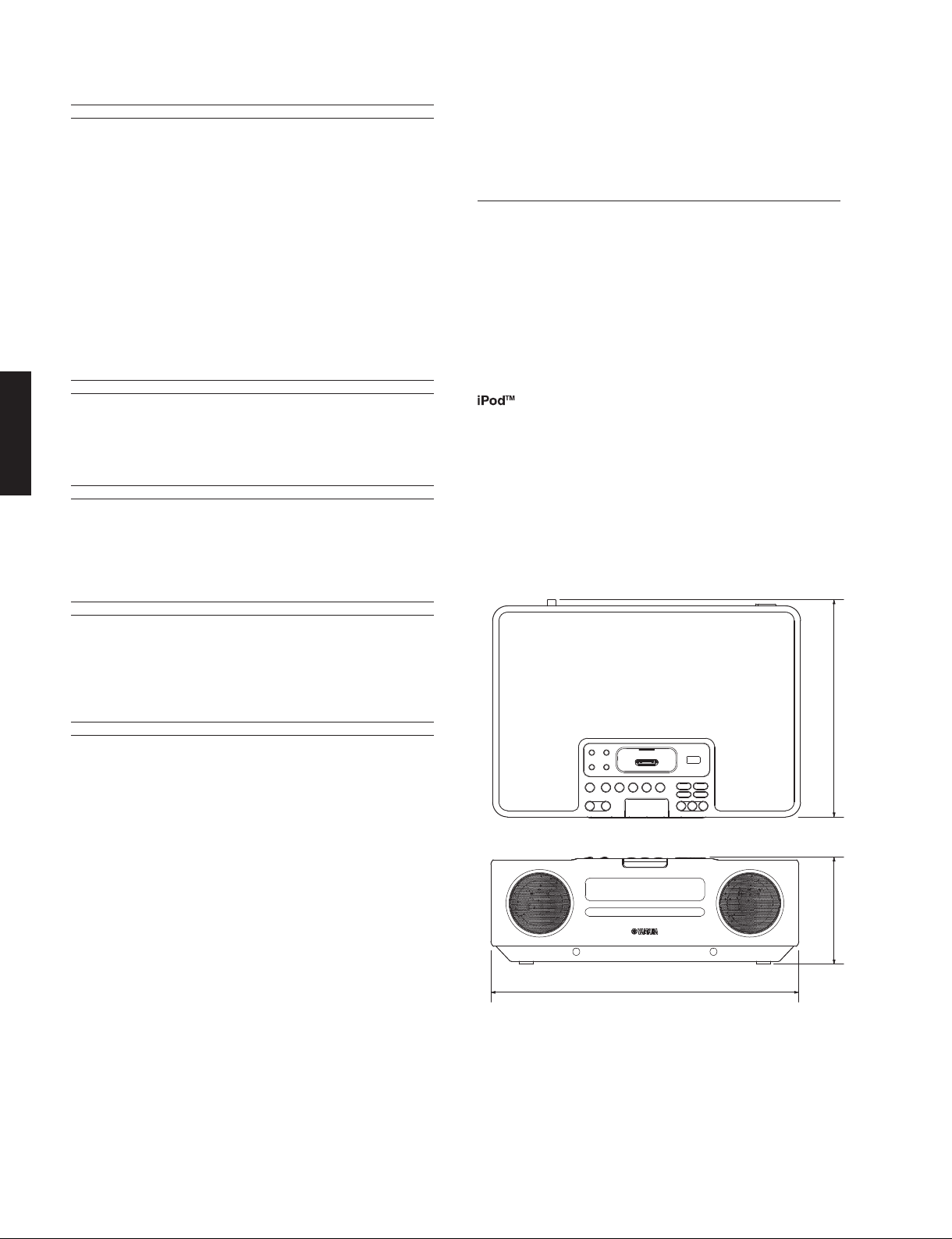
• DIMENSIONS /
付属品
L..................Singapore model
V ...................... Taiwan model
J ................... Japanese model
寸法図
■ Others /
Alarm: Alarm Function /
DSP: DSP Mode /
■ General /
Power Supply /
U model ..................................................................AC 120 V, 60 Hz
T model ................................................................... AC 220 V, 50 Hz
K model .................................................................. AC 220 V, 60 Hz
G model .................................................................. AC 230 V, 50 Hz
L model ........................................................ AC 220-240 V, 50/60Hz
V model ............................................................AC 110-120 V, 60 Hz
J model .............................................................. AC 100 V, 50/60 Hz
Power Consumption /
Standby Power Consumption (reference data) /
待機時消費電力 ( 参考値 )
.....................................................................1.0 W or less (Standby)
Dimensions (W x H x D) /
............................... 350 x 120 x 240 mm (13-3/4" x 4-3/4" x 9-7/16")
Weight /
TSX-1
TSX-120
Finish /
TSX-130
TSX-120
その他
アラーム機能
Alarm Mode /
............................................Beep, Music, Beep + Music
総合
電源電圧
質量
30
...................................................................... 4.0 kg (8 lbs. 13 oz.)
........................................................................ 3.7 kg (8 lbs. 3 oz.)
仕上げ
Black color ..............................................U, T, K, G, L, V, J models
White color ...............................................U, T, K, G, L, V, J models
Black color ......................................................U, T, G, L, J models
White color .......................................................U, T, G, L, J models
アラームモード
DSPモード
................................................20 W
消費電力
寸法(幅 × 高さ × 奥行き)
........ Dual Alarm, Snooze
(Music: iPod, FM, CD, USB)
........... Normal, Mild, Heavy, Live
240 (9-7/16")
120 (4-3/4")
350 (13-3/4")
Unit: mm (inch)
単位:mm(インチ)
12
Page 13
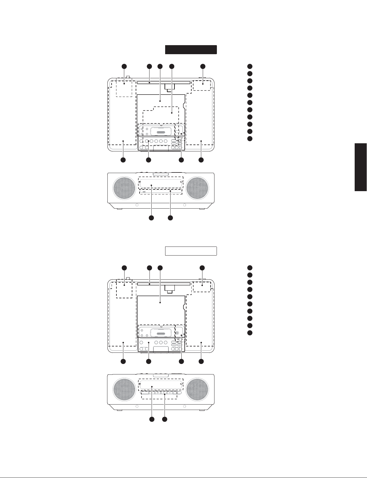
■ INTERNAL VIEW
TSX-130/TSX-120
TSX-130
Top view
Front view
1 2 3 4 5
6 7 8 9
10 11
1
FM Tuner
2
POWER (1) P.C.B.
3
MAIN P.C.B.
4
CD P.C.B.
5
POWER (7) P.C.B.
6
Speaker Box Ass’y L
7
POWER (2) P.C.B.
8
POWER (4) P.C.B.
9
Speaker Box Ass’y R
10
POWER (3) P.C.B.
11
Loader Mechanism Unit
TSX-130/TSX-120
Top view
Front view
TSX-120
1 2 3 4
5 6 7 8
9 10
1
FM Tuner
2
POWER (1) P.C.B.
3
MAIN P.C.B.
4
POWER (7) P.C.B.
5
Speaker Box Ass’y L
6
POWER (2) P.C.B.
7
POWER (5) P.C.B.
8
Speaker Box Ass’y R
9
POWER (3) P.C.B.
10
POWER (6) P.C.B.
13
Page 14
TSX-130/TSX-120
TSX-130/TSX-120
■ DISASSEMBLY PROCEDURES /
Disassembly procedure of TSX-130 is described to
represent similar models.
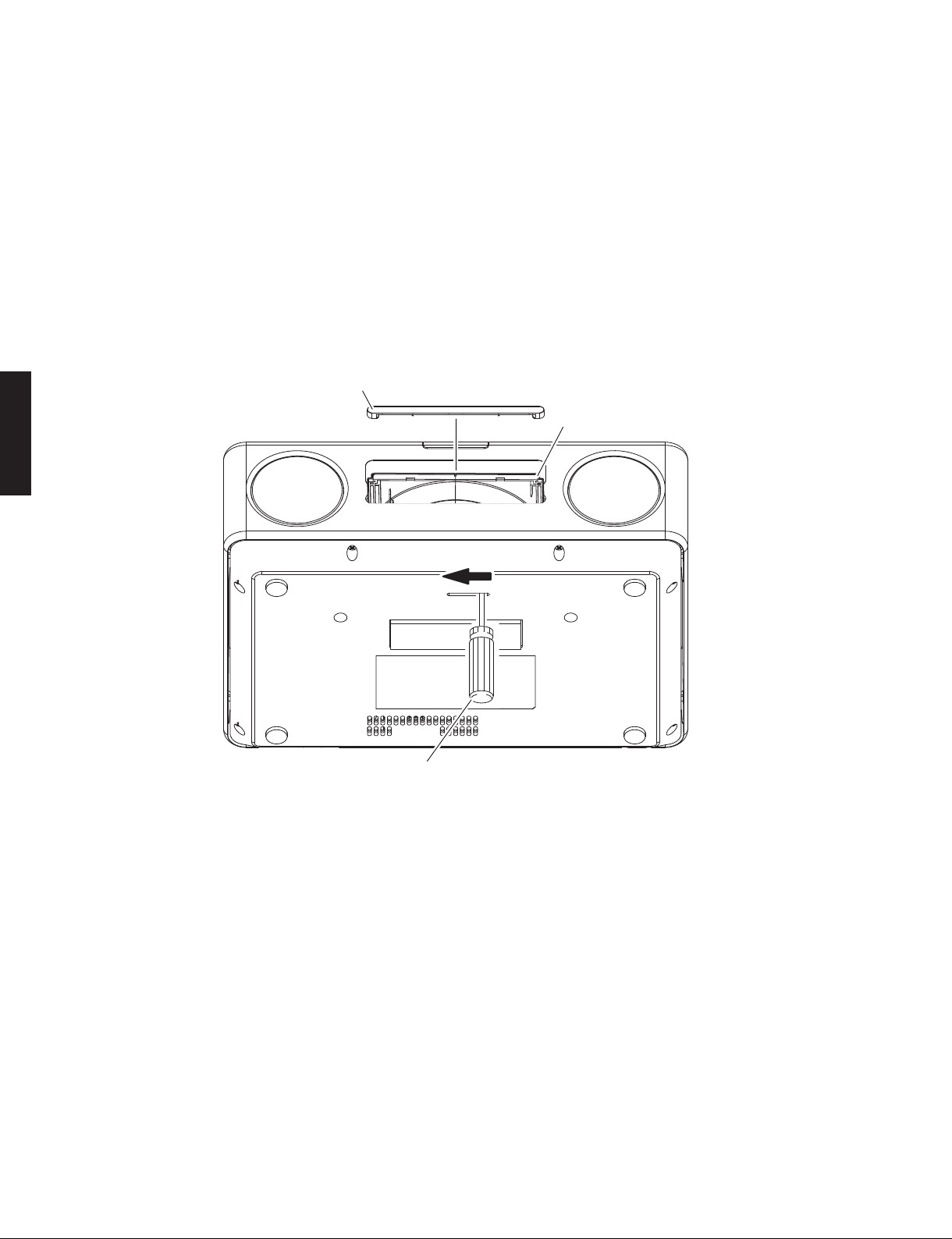
● How to manually eject the disc tray
a. Using an Allen hex socket screwdriver (2.5 mm),
move the slider in the direction indicated in the
figure below until the disc tray comes out. (Fig. 1)
b. Gently pull the disc tray comes out.
Lid / リッド
分解手順
代表で、TSX-130 の分解手順を記載します。
● 手動でディスクトレイを開く方法
a. 6 角穴ネジ用ドライバー(2.5mm)で、スライダー
を図に示す矢印の方向に、ディスクトレイが出て
くるまで、動かします。(Fig.1)
b. ディスクトレイをそっと引き出します。
Disc tray
ディスクトレイ
14
An Allen hex socket screwdriver
6角 穴ネジ用ドライバー
Fig. 1
Page 15
TSX-130/TSX-120
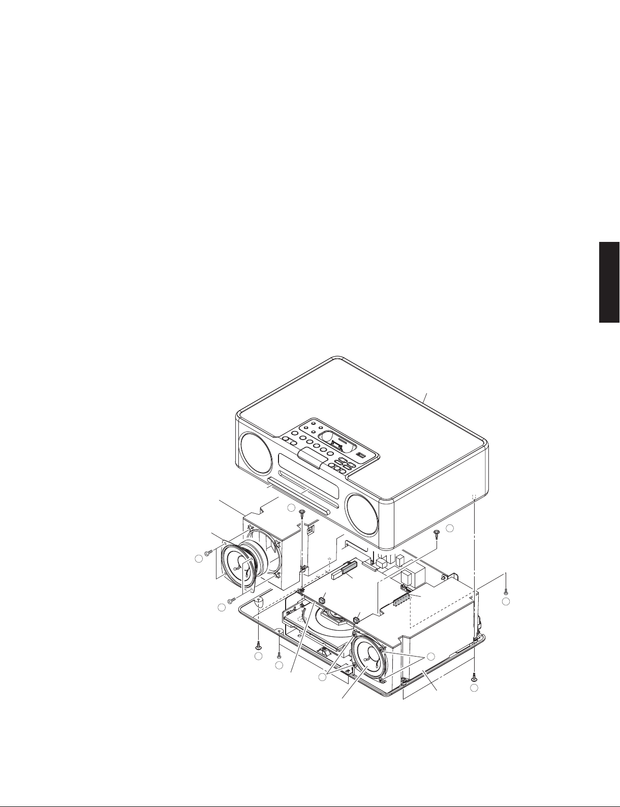
1. Removal of Top Panel Ass’y
a. Open the disc tray, remove the lid and close the disc
tray. (Fig. 1)
b. Remove 4 screws (➀) and 3 screws (➁). (Fig. 2)
c. Pull up the top panel ass’y gradually. (Fig. 2)
d. Remove CB205 and CB207. (Fig. 2)
e. Remove the top panel ass’y. (Fig. 2)
2. Removal of Driver L and Driver R
Since the same procedure is used to remove speaker
unit L and speaker unit R, removal of speaker unit L
is described here to represent both units.
a. Remove screw (➂). (Fig. 2)
b. Remove CB211. (Fig. 2)
c. Remove the speaker box L ass’y. (Fig. 2)
d. Remove 4 screws (➃). (Fig. 2)
e. Remove the driver L. (Fig. 2)
1. トップパネル ASSY の外し方
a. ディスクトレイを開き、リッドを外し、ディスクト
レイを閉じます。(Fig.1)
b. ①のネジ 4 本、②のネジ 3 本を外します。(Fig.2)
c. トップパネル ASSY をゆっくり持ち上げます。(Fig.2)
d. CB205、CB207 を外します。(Fig.2)
e. トップパネル ASSY を取り外します。(Fig.2)
2. スピーカーユニット L、スピーカーユニット R
の外し方
スピーカーユニット L とスピーカーユニット R の外
し方は同じなので、ここでは、両ユニットを代表し
てスピーカーユニット L の外し方を記述します。
a. ③のネジ 1 本を外します。(Fig.2)
b. CB211 を外します。(Fig.2)
c. SP ボックス LASSY を取り外します。(Fig.2)
a. ④のネジ 4 本を外します。(Fig.2)
b. スピーカーユニット L を取り外します。(Fig.2)
TSX-130/TSX-120
Speaker box L ass'y
SPボックスLASSY
Driver L
スピーカーユニットL
4
Top panel ass'y
トップパネルASSY
Lid
リッド
4
1
MAIN P.C.B.
3
CB211
2
4
Driver R
スピーカーユニットR
CB205
CB210
3
CB207
4
1
Speaker box R ass'y
SPボックスRASSY
2
Fig. 2
15
Page 16
TSX-130/TSX-120
TSX-130/TSX-120
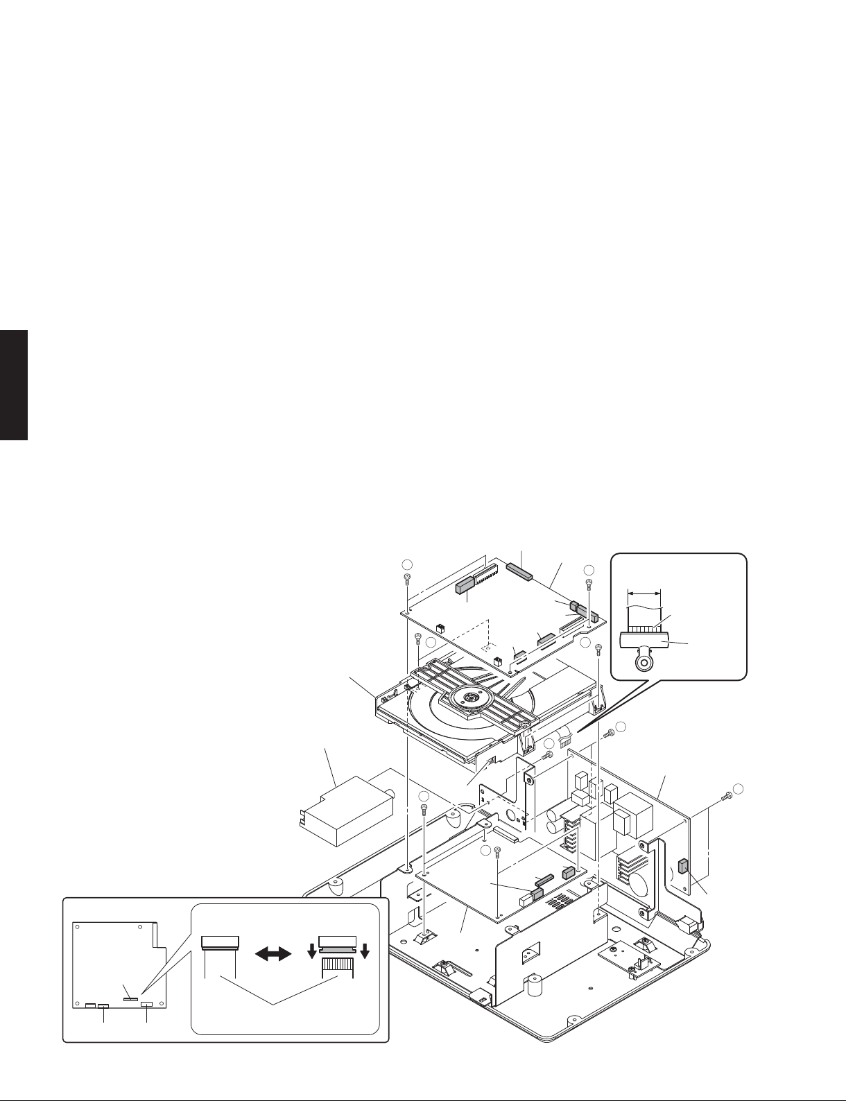
3. Removal of MAIN P.C.B.
a. Remove 4 screws (➄). (Fig. 3)
b. Remove CB201,CB204,CB208,CB209,CB214 and
CB215. (Fig. 3)
c. Remove the MAIN P.C.B.. (Fig. 3)
4. Removal of Loader Mechanism Unit
a. Remove 4 screws (➅). (Fig. 3)
b. Pull up the loader mechanism unit gradually. (Fig. 3)
c. Remove CB602 and connector W601. (Fig. 3)
d. Unlock and remove CB604, and ground the terminal
side of the flexible flat cable with a clip or the like.
(Fig. 3)
e. Remove the loader mechanism unit. (Fig. 3)
5. Removal of CD P.C.B.
a. Remove 4 screws (➆). (Fig. 3)
b. Remove CB610. (Fig. 3)
c. Remove the CD P.C.B.. (Fig. 3)
6. Removal of POWER (1) P.C.B.
a. Remove 4 screws (➇). (Fig. 3)
b. Remove CB1. (Fig. 3)
c. Remove the POWER (1) P.C.B.. (Fig. 3)
7. Removal of FM Tuner
a. Remove 2 screws (➈). (Fig. 3)
b. Remove the FM tuner. (Fig. 3)
3. MAINP.C.B. の外し方
a. ⑤のネジ 4 本を外します。(Fig.3)
b. CB201、CB204、CB208、CB209、CB214、CB215 を
外します。(Fig.3)
c. MAINP.C.B. を取り外します。(Fig.3)
4. ローダーメカユニットの外し方
a. ⑥のネジ 4 本を外します。(Fig.3)
b. ローダーメカユニットをゆっくり持ち上げます。
(Fig.3)
c. CB602、コネクター W601 を外します。(Fig.3)
d. ロックを解除して CB604を外し、カード電線の端子
面をクリップ等でアースします。(Fig.3)
e. ローダーメカユニットを取り外します。(Fig.3)
5. CDP.C.B. の外し方
a. ⑦のネジ 4 本を外します。(Fig.3)
b. CB610 を外します。(Fig.3)
c. CDP.C.B. を取り外します。(Fig.3)
6. POWER(1)P.C.B. の外し方
a. ⑧のネジ 4 本を外します。(Fig.3)
b. CB1 を外します。(Fig.3)
c. POWER(1)P.C.B. を取り外します。(Fig.3)
7. FM チューナーの外し方
a. ⑨のネジ 2 本を外します。(Fig.3)
b. FM チューナーを取り外します。(Fig.3)
CD P.C.B.
Loader mechanism unit
ローダーメカユニット
FM tuner
FMチューナー
CB604
Locked Unlocked
5
6
Connector
7
CB204
W601
CB602
CD P.C.B.
7
CB201
CB209
CB214
CB604
MAIN P.C.B.
CB215
CB208
9
CB610
17 mm
5
(0.67")
Terminal side
端子面
6
8
POWER P.C.B.
Clip
クリップ
8
CB1
16
CB604
Flexible flat cable
CB7CB602
カード電線
Fig. 3
Page 17
TSX-130/TSX-120
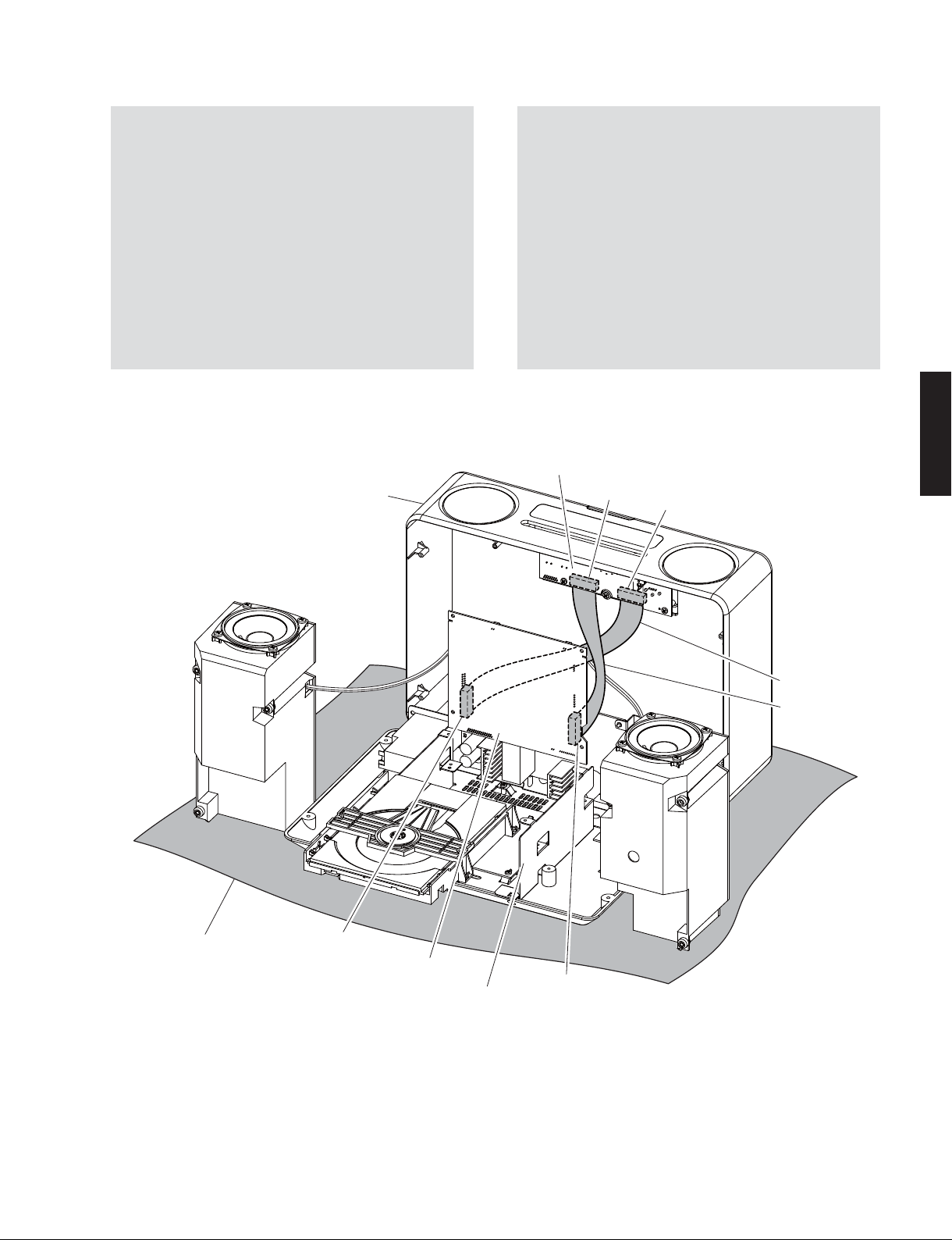
When checking the P.C.B.s:
• Spread the rubber sheet and cloth. Then, place this
unit on them as shown below and check it. (Fig. 4)
• Reconnect all cables (connectors) that have been
disconnected. Be sure to use the extension cable for
servicing for the following section.
MF120350 (20P, 350mm):
CB207 of MAIN P.C.B. to CB756 of POWER (2) P.C.B.
MF121350 (21P, 350mm):
CB205 of MAIN P.C.B. to CB754 of POWER (2) P.C.B.
• When connecting the flexible flat cable, be careful
with polarity.
Top panel ass'y
トップパネルASSY
P.C.B.をチェックする場合には:
・ ゴムシートと布を敷き、本機を下図のように置いて
チェックします。(Fig.4)
・ 外したケーブル(コネクター)をすべて接続します。
ただし次の区間は、サービス用延長ケーブルを使用
してください。
MF120350(20P、350mm):
MAINP.C.B. の CB207 〜 POWER(2)P.C.B. の CB756
MF121350(21P、350mm):
MAINP.C.B. の CB205 〜 POWER(2)P.C.B. の CB754
・ フラットケーブルを接続する際、極性に注意してく
ださい。
POWER (2) P.C.B.
CB750
CB754
TSX-130/TSX-120
Rubber sheet and cloth
ゴ ム シ ートと布
CB205
MAIN P.C.B.
Chassis
シャーシ
Fig. 4
MF121350
MF120350
CB207
17
Page 18

TSX-130/TSX-120
TSX-130/TSX-120
■ UPDATING FIRMWARE /
After replacing the following parts with the replacement
parts, update the latest firmware according to the
following procedure.
MAIN P.C.B.
Microprocessor (IC201) of MAIN P.C.B.
ファームウェアの書き込み
● Required tools
• Program downloader program
....................................................... FlashSta.exe
• Firmware
....................................................... tsx_xxxx.mot
.......................................................... tsx_xxxx.id
• RS232C cross cable “D-sub 9 pin female”
(Specifications)
Pin No.2 RxD Pin No.2 RxD
Pin No.3 TxD Pin No.3 TxD
Pin No.5 GND Pin No.5 GND
Pin No.7 RTS Pin No.7 RTS
Pin No.8 CTS Pin No.8 CTS
• RS232C conversion adaptor (Part No.: WR492800)
下記の部品をサービス部品に交換した場合、下記の手順に
より最新のファームウェアの書き込みを行ってください。
MAINP.C.B.
Microprocessor(IC201)ofMAINP.C.B.
● 必要なツール
・ プログラム書き込み用プログラム
............................................................................... FlashSta.exe
・ ファームウェア
..............................................................................tsxxxxx.mot
...................................................................................tsxxxxx.id
・ RS232C クロスケーブル “D-sub9pin メス”
(仕様)
PinNo.2RxD PinNo.2RxD
PinNo.3TxD PinNo.3TxD
PinNo.5GND PinNo.5GND
PinNo.7RTS PinNo.7RTS
PinNo.8CTS PinNo.8CTS
・ RS232C変換アダプター(部品番号:WR492800)
● Preparation and precautions before starting
the operation
• Download firmware downloader program and
firmware from the specified source to the same
folder of the PC.
• Prepare the above specified RS232C cross cable.
• While writing, keep the other application software
on the PC closed.
It is also recommended to keep the software on
the task tray closed as well.
● Confirmation of firmware version and checksum
Before and after updating the firmware, check the
firmware version and checksum by using the selfdiagnostic function menu.
Start up the self-diagnostic function of this unit and
select the “1. ROM VER/SUM” menu. (See “SELFDIAGNOSTIC FUNCTION”)
Have the firmware version and checksum displayed
by using sub-menu, and note down them.
1-1VER:D047
● 操作前の準備と注意
・ PC へ指定のダウンロード先からファームウェア
アップグレードプログラムおよび、ファームウェ
アを同じフォルダにダウンロードしてください。
・ RS232C クロスケーブルは必ず上記仕様のものを
用意してください。
・ 書き込み時は、PC 上の他のアプリケーションソ
フトは閉じてください。
さらに、タスクトレイ上にあるソフトも閉じてお
くことを推奨します。
● ファームウェアのバージョンおよびチェックサ
ムの確認
ファームウエア更新の前後に、ファームウエアのバー
ジョンとチェックサムをダイアグで確認します。
本機のダイアグを起動し、「1.ROM VER/SUM」メ
ニューを選択します。(「ダイアグ(自己診断機能)」
参照)
サブメニューでファームウェアのバージョンと
チェックサムを表示し、それらを書きとめます。
1-1 Firmware version
18
1-2SUM:5404
1-2 Checksum
Page 19
TSX-130/TSX-120
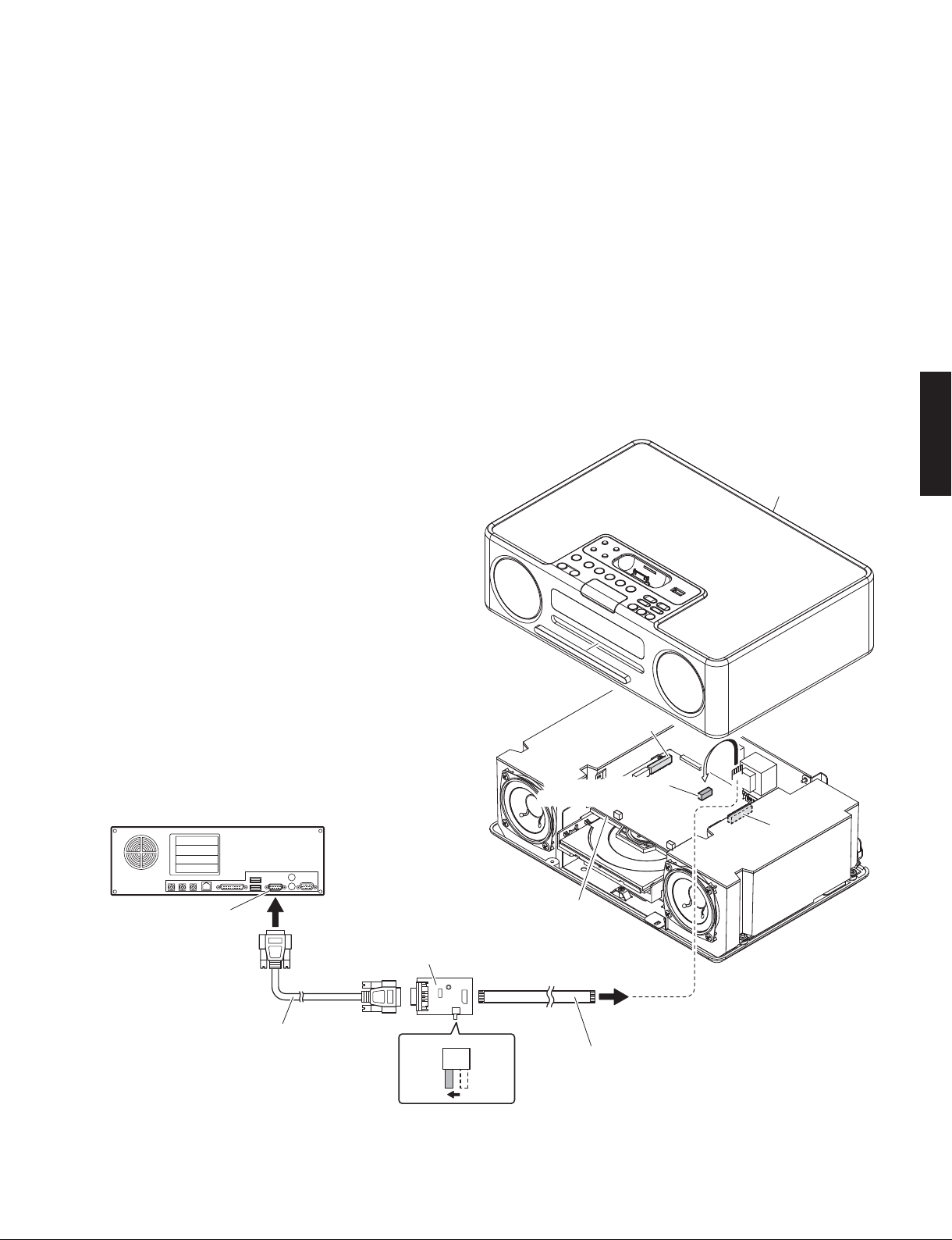
● Connection
1. Remove the top panel ass’y and then remove
CB205 and CB207.
(See “DISASSEMBLY PROCEDURES”.)
* The firmware can be written even when CB205
and CB207 are removed.
2. Set the switch (SW301) of RS232C conversion
adaptor to the “FLASH UCOM” position. (Fig. 1)
3. Connect the writing port (CB212 of MAIN P.C.B.)
of this unit to the serial port (RS232C) of the PC
with RS232C cross cable, RS232C conversion
adaptor and flexible flat cable as shown below.
(Fig. 1)
● 接続
1. トップパネル ASSY を外し、CB205、CB207 を外
します。
(「分解手順」を参照してください。)
※ CB205、CB207を外した状態でも、ファーム
ウェアの書き込みはできます。
2. RS232C 変換アダプターのスイッチ(SW301)
“FLASHUCOM” 側に設定します。(Fig.1)
3. 本機の書き込み用ポート(MAINP.C.B. の CB212)
と PC のシリアルポート(RS232C)を下記のよう
に接続します。(Fig.1)
TSX-130/TSX-120
Top panel ass'y
トップパネルASSY
PC
Serial port (RS232C)
RS232C cross cable /
RS232Cクロスケーブル
MAIN P.C.B.
RS232C conversion adaptor /
RS232C変換アダプター
SW301
FLASH
UCOM
OTHER
Fig. 1
CB205
Writing port (CB212) /
書き込み用ポート(CB212)
CB207
Flexible flat cable (9P) /
カード電線(9P)
19
Page 20
TSX-130/TSX-120
TSX-130/TSX-120
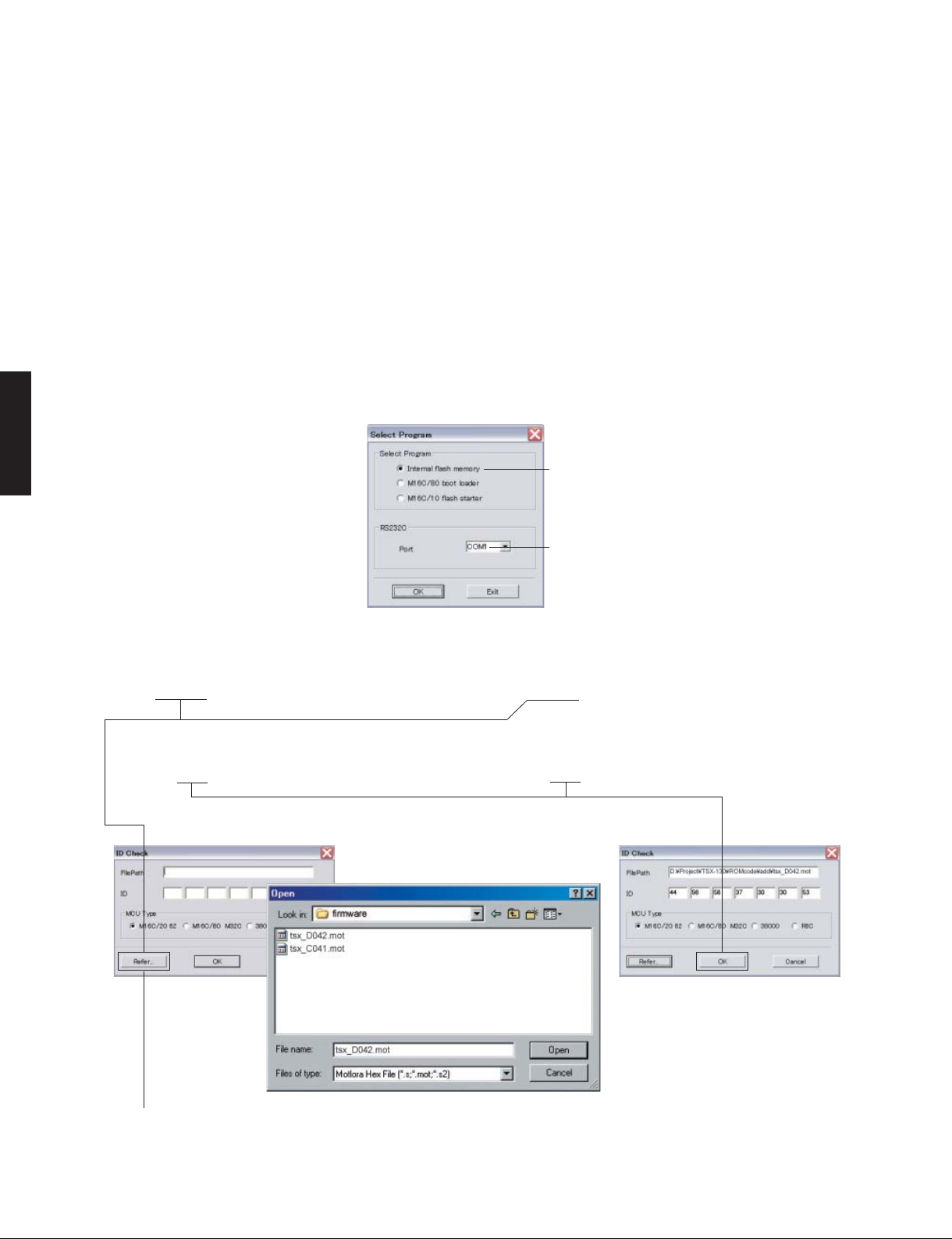
● Operation procedures
1. Connect the power cable of this unit to the AC
outlet.
2. Start up FlashSta.exe. (Fig. 2)
3. Select the data to be transmitted and port. (Fig. 2)
• Select Program
Select Internal flash memory.
• RS232C
Select the port of RS-232C
* For selection of the port, COM1 to 4 can
be used.
As COM5 or higher port cannot be used,
select out of COM 1 to 4 of the setting on
the PC side.
● 操作方法
1. 本機の電源コードを AC コンセントに接続します。
2. FlashSta.exe を起動します。(Fig.2)
3. 送信データ、ポートを選択します。(Fig.2)
・ SelectProgram
Internalflashmemory を選択します。
・ RS232C
接続している RS-232 Cポートを選択します。
※ ポートの選択は COM1 〜 4 までが使用で
きます。
COM5 以上は使用できませんので、PC 側
の設定で COM1 〜 4 を選択してください。
Select Internal flash memory
このボタン(Internalflashmemory)を選択します
Select the port of RS-232C
接続している RS-232C ポートを選択します
4. Click [Refer...], and select the firmware name.
(Fig. 3)
* The ID and MCU Type are loaded automati-
cally when the file is selected. (Fig. 3)
Click [OK]. (Fig. 3)
Fig. 2
4.[Refer...]をクリックし、書き込むファームウェア
を選択します。(Fig.3)
※ ID、および MCUType は書き込みファイル選
択後、自動的に取り込まれます。(Fig.3)
[OK]をクリックします
When [Refer...] is clicked, the “Open” is displayed.
[Refer...]をクリックすると「ファイルを開く」が表示されます
20
Fig. 3
Page 21
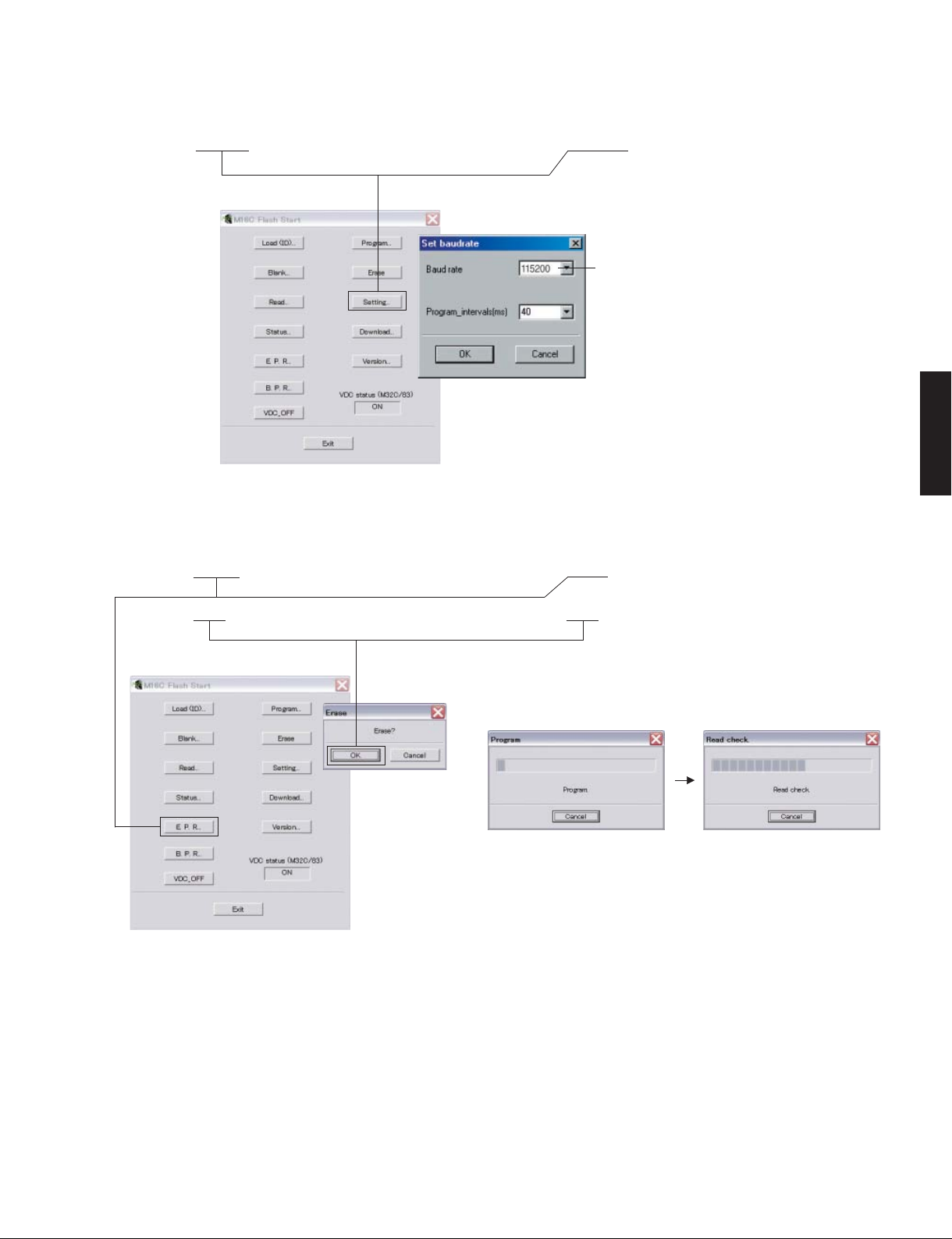
TSX-130/TSX-120
5. Click [Setting], and set the baud rate. (Fig. 4)
6. Click [E.P.R.], then the “Erase” screen is displayed.
(Fig. 5)
7. Click [OK] to start writing. (Fig. 5)
Fig. 4
5.[Setting]をクリックし、通信速度の設定を行い
ます。(Fig.4)
Select 115200 bps for the baud rate and 40 ms for
the program intervals.
* Reduce the baud rate if a transmission error
occurs frequently.
通信速度は 115200bps、時間幅は 40ms を選択し
ます。
※ 送信エラーが多発する場合は、通信速度を下
げてください。
6.[E.P.R]をクリックすると、「Erase」が表示されま
す。(Fig.5)
7.[OK]をクリックして書き込みを開始します。
(Fig.5)
TSX-130/TSX-120
Fig. 5
Writing being executed.
書き込み中
21
Page 22
TSX-130/TSX-120
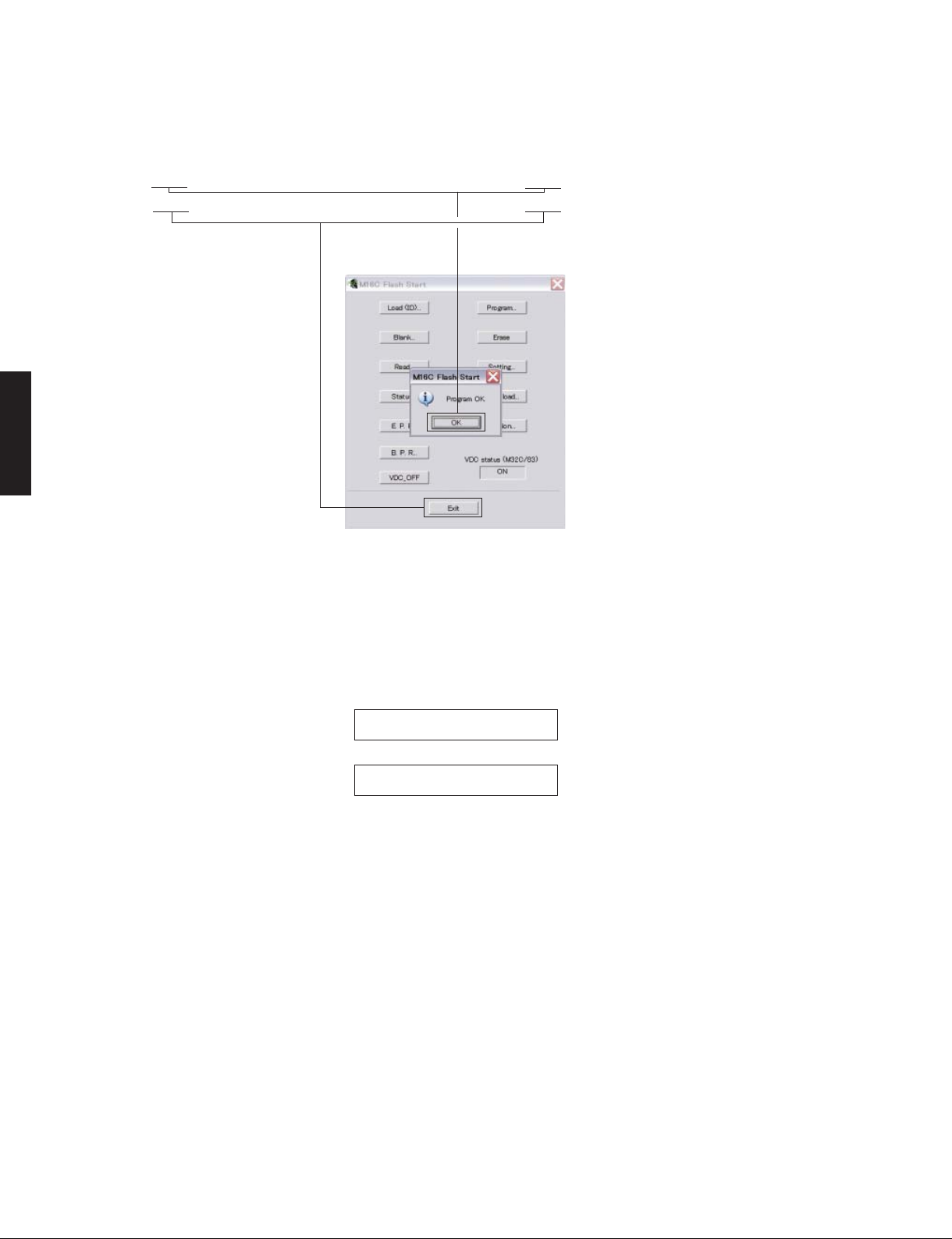
TSX-130/TSX-120
8. When writing of the firmware is completed, the
screen appears as shown below. (Fig. 6)
Click [OK]. (Fig. 6)
9. Click [Exit] to end FlashSta.exe. (Fig. 6)
8. プログラムの書き込みが完了すると、以下の画面
が表示されます。
[OK]をクリックします。(Fig.6)
9. [Exit]をクリックして FlashSta.exe を終了します。
(Fig.6)
Fig. 6
10. Check that the firmware version and checksum
are the same as written ones by using the selfdiagnostic function menu.
1-1VER:D047
1-2SUM:5404
* When the firmware version and checksum
are different from written ones, perform the
“UPDATING FIRMWARE” procedure all over
again.
11. Disconnect the power cable of main unit from the
AC outlet.
10.ファームウエアのバージョンとチェックサムが、
書き込まれたものと同じであることをダイアグで
確認します。
1-1 Firmware version
1-2 Checksum
※ ファームウェアのバージョンとチェックサム
が、書き込まれたものと異なる場合、「ファー
ムウェアの書き込み」をもう一度やり直して
ください。
11.本機の電源コードを AC コンセントから抜きます。
22
Page 23

TSX-130/TSX-120
● Initializing of this unit
* After updating firmware, be sure to initialize this
unit.
Start up the self-diagnostic function of this unit and
select the “B. FACTORY PRESET” menu. (See “SELFDIAGNOSTIC FUNCTION”)
Select the “PRESET RSRV” (Initialization reserved)
and turn off the power to this unit.
PRESET INHIBIT (Initialization inhibited) /
初期化禁止
B-1PRESETINH B-2PRESETRSRV
● 本機の初期化
※ ファームウェアの書き込み後は、必ず本機を初期
化してください。
本機のダイアグを起動し、「B.FACTORYPRESET」メ
ニューを選択します。(「ダイアグ(自己診断機能)」
参照)
「PRESETRSRV」(初期化予約)を選択し、本機の電源
を切ります。
PRESET RESERVED (Initialization reserved) /
初期化予約
TSX-130/TSX-120
23
Page 24
TSX-130/TSX-120
TSX-130/TSX-120
■ SELF-DIAGNOSTIC FUNCTION /
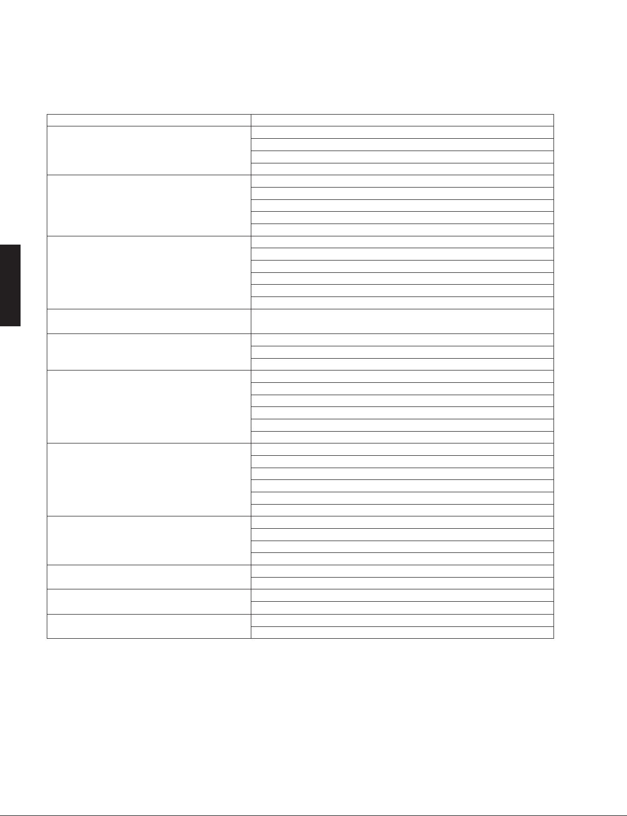
There are 11 main menu items, each of which has submenu items. Listed in the table below are menu items and
sub-menu items.
MAIN MENU SUB MENU
1 ROM VER/SUM 1 MAIN VERSION
2 AUDIO TEST 1 iPod
3 FL CHECK 1 FL CHECK
4 iPod
5 MAIN PCB CHECK 1 ALL Check
6 CD CHECK 1 Laser Diode Check
7 SYSTEM MONITOR 1 PS1 / PS2
8 PROTECTION HISTORY 1 LAST
9 SET INFORMATION 1 MODEL
A SOFT SWITCH
B FACTORY PRESET 1 PRESET INH
(Not applied to these models. /
は適用されません。
のモデルには適用されません。
)
(Not applied to these models. /
このモデルに
こ
)
ダイアグ(自己診断機能)
メインメニューは 11個あり、そのそれぞれにサブメ
ニューがあります。下表はメニュー一覧です。
2 MAIN CHECKSUM
3 CD VERSION
4 USB VERSION
2 TUNER
3CD
4 USB
5 AUX
2 FL DISPLAY OFF
3 FL DISPLAY ALL
4 FL DIMMER
5 FL CHECK PATTERN1
6 FL CHECK PATTERN2
1 CONNECTION CHECK/UART LOOPBACK TEST
2 I2C Check
3 RTC SELF CHECK
2 Spindle Motor Check
3 Feed Motor Check
4 Focus Check
5 Tracking
6 Module Upgrade
2 LUMINANCE
3 AUDIO DETECT
4 MODEL
5 DESTINATION
6 PANEL KEY(KEY0/KEY1/KEY2)
2 HISTORY 1
3 HISTORY 2
4 HISTORY 3
2 DEST
1 SW MODE
2 DEST
2 PRESET RSRV
24
Page 25
TSX-130/TSX-120
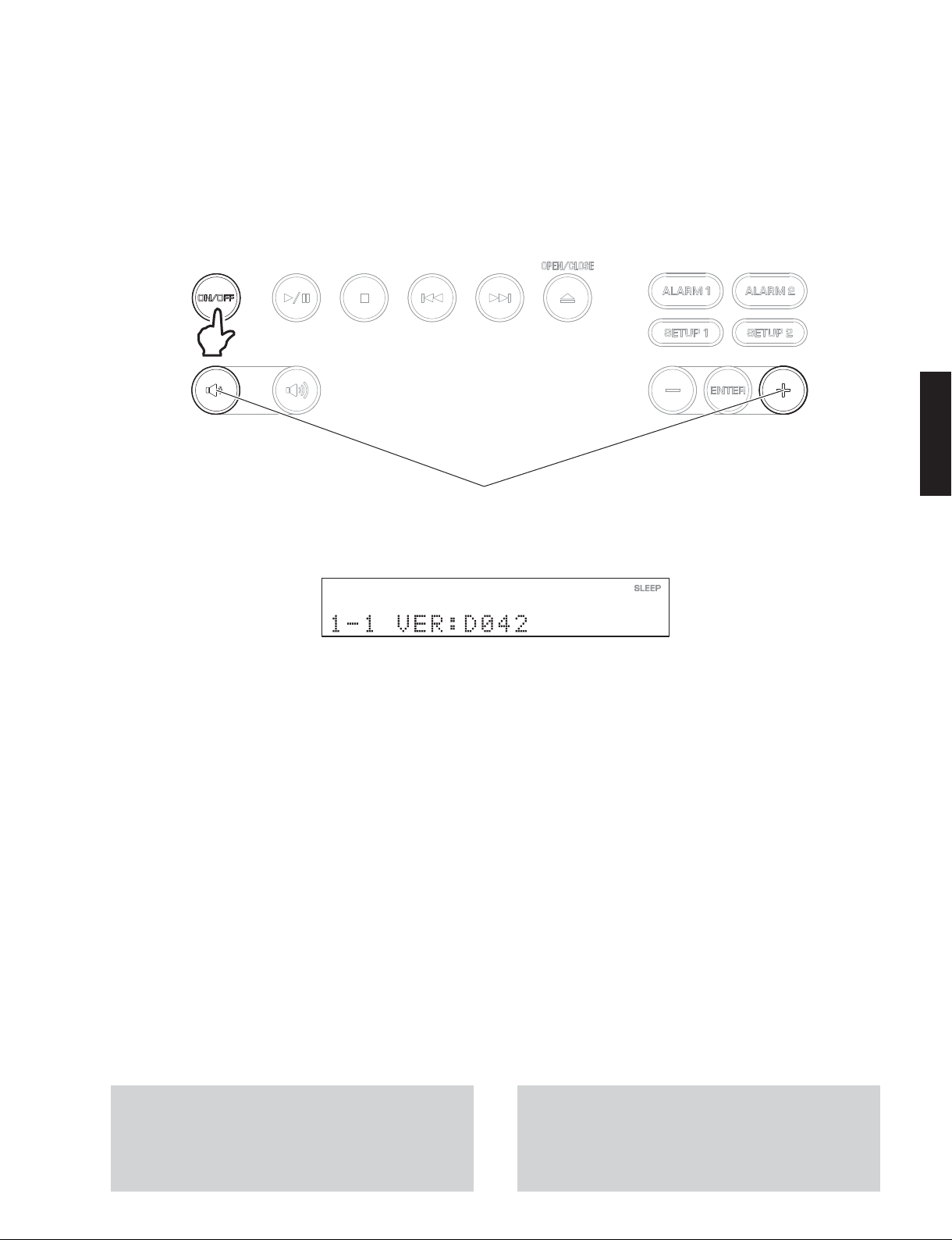
● Starting Self-Diagnostic Function
While pressing those 2 keys of this unit as indicated in the
figure below, press the “ON/OFF” key to turn on the power.
The self-diagnostic function mode is activated.
Keys of this unit /
While pressing these keys, turn on the power.
これらのキーを同時に押しながら、電源を入れます。
Display /
● ダイアグの起動
本機の下図に示す 2 つのキーを押しながら “ON/OFF” キー
を押して電源を入れます。
ダイアグが起動します。
本機キー
TSX-130/TSX-120
ディスプレイ表示
● Starting Self-Diagnostic Function in the protection cancel mode
If the protection function works and causes hindrance to
trouble shoot, cancel the protection function as described
below, and it will be possible to enter the self-diagnostic
function mode.
(The protection functions except the excess current
detect function will be disabled.)
While pressing those 2 keys of this unit indicated in the
figure above, press the “ON/OFF” key to turn on the
power and keep pressing those 2 keys for 3 seconds or
longer.
The self-diagnostic function mode is activated with the
protection functions disabled.
In this mode, the “SLEEP” segment of the FL display of
this unit flashes to indicate that the mode is self-diagnostic function mode with the protection functions disabled.
CAUTION!
Using this product with the protection function disabled
may cause further damage to itself. Use special care
when using this mode.
● プロテクション解除モードでの起動
プロテクションが動作することにより、故障箇所の診断
に支障をきたすような場合は、次の方法によりプロテク
ションを解除した状態でダイアグモードに入ることがで
きます。
(過電流検出以外のプロテクション動作を解除します)
本機の上図に示す 2 つのキーを押しながら “ON/OFF” キー
を押して電源を入れ、2 つのキーを 3 秒以上押し続けます。
プロテクションを解除した状態でダイアグが起動します。
このモードでは本機 FL の “SLEEP” セグメントが点滅し、
プロテクションを解除した状態でのダイアグモードであ
ることを知らせます。
注意!
プロテクションを解除した状態でのダイアグモードは、
危険な状態でもプロテクションが作動しないため、動作
させると、機器を破壊することがあります。このモード
を使用する場合は十分注意してください。
25
Page 26
TSX-130/TSX-120
TSX-130/TSX-120
● Canceling Self-Diagnostic Function
1. Before canceling self-diagnostic function, execute
setting for FACTORY PRESET of main menu No. B
(Memory initialization inhibited or Memory initialized).
* In order to keep the user memory stored, be sure
to select PRESET INH (Memory initialization inhibited).
2. Press the “ON/OFF” key of this unit to turn off the
power.
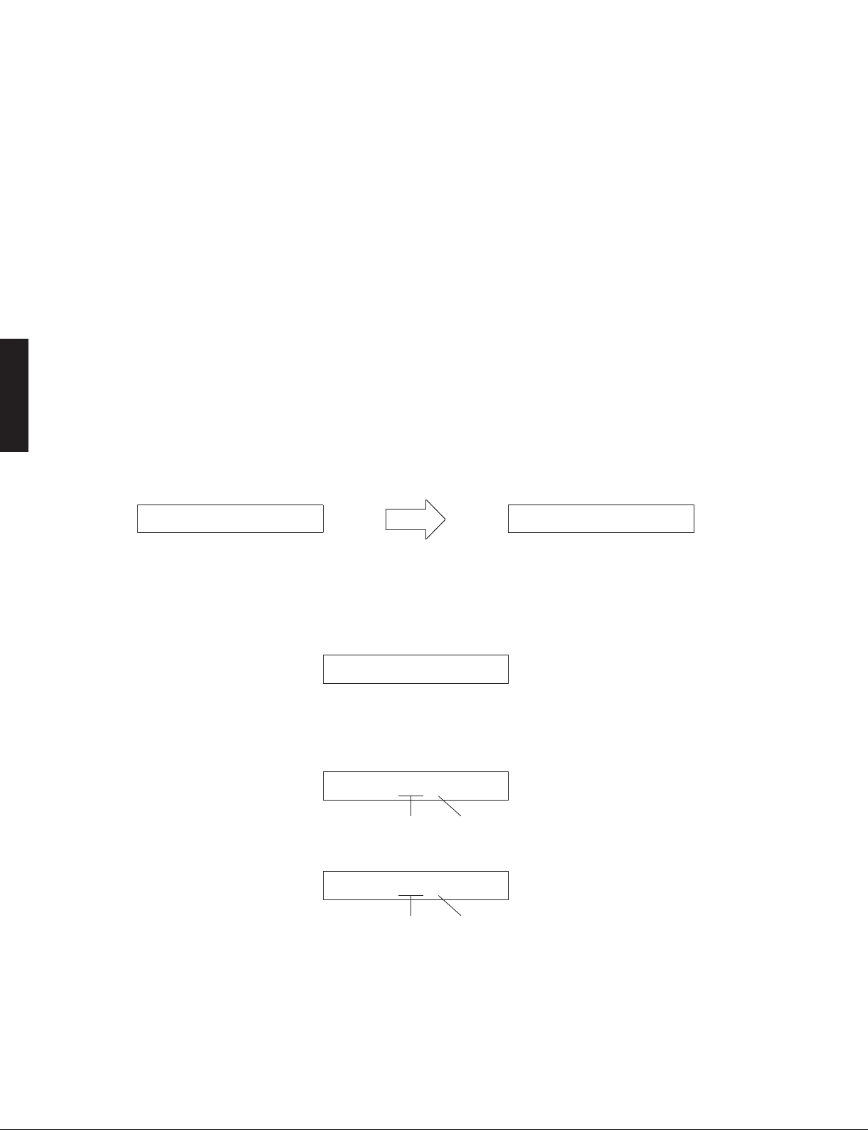
● Display provided when Self-Diagnostic Function started
The FL display of this unit displays the protection function
history data then the main menu (sub-menu MAIN CPU
VERSION of main menu No. 1 ROM VER/SUM) a few
seconds later.
When there is no history of protection function:
Opening message /
オープニング表示
After a few seconds /
● ダイアグの解除
1. ダイアグを解除する前に、メインメニュー No.B の
FACTORYPRESET(メモリーの初期化禁止 / またはメ
モリーの初期化)の設定をします。
※ ユーザーメモリーを保持したい場合は、必ず
PRESETINH(メモリー初期化禁止)を選択してく
ださい。
2. 本機の “ON/OFF” キーを押して電源を切ります。
● ダイアグ起動時の表示
本機の FL ディスプレイにプロテクション履歴情報と
ファームウェアバージョン(英 1文字)が表示されます。
数秒後、メインメニュー No.1「ROMVER/SUM」のサブメ
ニュー「1-1MAINCPUVERSION」が表示されます。
プロテクション履歴がない場合:
Main menu display /
数秒後
メインメニュー表示
NoProtection 1-1VER:D042
When there is a history of protection function:
When there is a history of protection function due to
abnormal amplifier section
D-AMPError
When there is a history of protection function due to
abnormal voltage in the power supply section
PS1(AD:xxxH)
A/D conversion value of voltage /
A/D conversion value of voltage /
電圧の A/D 変換値
PS2(AD:xxxL)
電圧の A/D 変換値
プロテクション履歴がある場合:
アンプ部の異常によるプロテクション履歴がある場合
電源部の電圧異常によるプロテクション履歴がある場合
H: High
L: Low
H: High
L: Low
For details of protection functions, refer to the main menu
No. 7-1 PS1/PS2.
26
プロテクションの詳細は、メインメニュー No.7-1PS1/
PS2 を参照してください。
Page 27

TSX-130/TSX-120
Note)
• Applying the power to this unit without correcting
the abnormality can be dangerous and cause
additional circuit damage.
To avoid this, if protection function has been
activated 3 times continuously, the power will not
turn on even when the “ON/OFF” key is pressed.
In order to turn on the power again, disconnect the
power cable of this unit from the AC outlet once and
then reconnect it again.
● History of protection function
When the protection function has worked, its history
is stored in memory with a backup. Even if no
abnormality is noted while servicing the unit, an
abnormality which has occurred previously can be
defined as long as the backup data has been stored.
The history of the protection function is cleared when
self-diagnostic function is cancelled by selecting
PRESET RSRV (Memory initialized) of main menu No.
B or when the backup data is erased.
注意!
・ 異常状態のまま本機の電源を入れると、危険な状態
になり、さらに回路が損傷を受ける原因になります。
そのため連続してプロテクションが働いた場合、3
回目以降 “ON/OFF” キーを押しても電源が入らなく
なります。
再度電源を入れる場合、一度本機の電源コードを AC
電源コンセントから抜いて接続し直してください。
TSX-130/TSX-120
● プロテクションの履歴
プロテクションが働いた場合、履歴をバックアップ
して記憶しています。修理のときに異常が認められ
なくても、バックアップが残っていれば、お客様の
ところで起きた異常を区別できます。
メインメニュー No.B で PRESETRSRV(メモリーの
初期化)を選んでダイアグを解除した場合、または
バックアップが消えた場合に、プロテクションの履
歴はクリアされます。
27
Page 28

TSX-130/TSX-120
TSX-130/TSX-120
● Operation procedure of Main menu and Sub-menu
There are 11 menu items, each of having sub-menu items.
Main menu selection
Select the main menu using “VOLUME +” (Forward) and
“VOLUME -” (Reverse) keys of this unit.
Sub-menu selection
Select the sub-menu using “ENTER” (Forward) key of this
unit.
Keys of this unit /
Sub-menu select
サブメニューの選択
● メインメニューとサブメニューの操作
ダイアグには 11 のメニューがあり、そのそれぞれにサブ
メニューがあります。
メインメニューの選択
“VOLUME+” キー(順送り)、“VOLUME-” キー(逆送り)
で選択します。
サブメニューの選択
“ENTER” キー(順送り)で選択します。
本機キー
Reverse / 逆送り Forward / 順送り
Main menu select
メインメニューの 選択
● Functions in Self-Diagnostic Function mode
In addition to the self-diagnostic function menu items,
functions listed below are available.
• Input selection
• Muting
• Power on/off
• Master volume
* Functions related to the tuner and the set menu are
not available.
● Initial settings used to start Self-Diagnostic Function
The following initial setting is used when starting selfdiagnostic function.
When self-diagnostic function is canceled, this setting is restored to that before starting self-diagnostic function.
Master volume: 25
● ダイアグ中の機能
ダイアグメニューの他に、以下の機能が動作します。
・ インプット切り換え
・ ミューティング
・ 電源オン/オフ
・ マスターボリューム
※ チューナー関連、セットメニュー関連は機能しません。
● ダイアグ開始時の初期設定
ダイアグ開始時に以下のような設定になります。
ダイアグ解除時にはダイアグ開始前の状態に戻ります。
マスターボリューム:25
28
Page 29

TSX-130/TSX-120
● Details of Self-Diagnostic Function menu
1. ROM VER/SUM
The firmware version and checksum are displayed.
The checksum is obtained by adding the data at every
8 bits for each program area and expressing the result
as a 4-figure hexadecimal data.
* Numeric values in the figure example are for
reference.
1-1VER:D042
1-2SUM:5404
1-3CVER:33-00
1-1 MAIN VERSION
The firmware version of microprocessor (IC201 of MAIN P.C.B.) is displayed.
メインマイコン(MAINP.C.B. の IC201)のファームウェアバージョンを表示します。
1-2 MAIN CHECKSUM
The checksum value of microprocessor (IC201 of MAIN P.C.B.) is displayed.
メインマイコン(MAINP.C.B. の IC201)のチェックサムを表示します。
1-3 CD VERSION (TSX-130)
The firmware version of CD microprocessor (IC602 of CD P.C.B.) is displayed.
CD マイコン(CDP.C.B. の IC602)のファームウェアバージョンを表示します。
● ダイアグメニュー詳細
1. ROMVER/SUM
ファームウェアバージョン、チェックサムを表示し
ます。
チェックサムは、プログラムエリア別にデータを 8
ビットごとに加算していき、4 桁の 16 進データで現
したものです。
※ 図中の数値は参考例です。
TSX-130/TSX-120
1-4UBER:01.22
1-4 USB VERSION (TSX-130)
The firmware version of USB microprocessor (IC604 of CD P.C.B.) is displayed.
USB マイコン(CDP.C.B. の IC604)のファームウェアバージョンを表示します。
29
Page 30

TSX-130/TSX-120
TSX-130/TSX-120
2. AUDIO TEST
Using the sub-menu, the input source is changed as
shown below.
2-1AUDIOiPod
2-2AUDIOTUNER
2-3AUDIOCD
2-4AUDIOUSB
2-1 iPod™
iPod is selected.
iPod が選択されます。
2-2 TUNER
TUNER is selected. Initial value: 98.1MHz (U, T, K, G, L, V models) / 83.0MHz (J model)
チューナーが選択されます。(初期値:83.0MHz)
2-3 CD (TSX-130)
CD is selected.
CD が選択されます。
2-4 USB (TSX-130)
Reproduced at this time is the first piece of the music file in the USB flash memory
connected to the USB terminal of this unit.
a. Copy 2 or more music files from PC into the root folder of the USB flash memory.
b. Insert the USB flash memory to the USB terminal of this unit.
本機の USB 端子に接続された USB フラッシュメモリーの音楽ファイルの 1 曲目を再生し
ます。
a. USB フラッシュメモリーのルートフォルダに(PC から)音楽ファイルを 2 曲以上コピー
します。
b. USB フラッシュメモリーを本機の USB端子に接続します。
2. AUDIOTEST
サブメニュー操作により、入力ソースが以下のよう
に切り替わり。
30
2-5AUDIOAUX
2-5 AUX (TSX-120)
AUX is selected.
AUX(外部入力)が選択されます。
Page 31

TSX-130/TSX-120
3. FL CHECK
This menu is used to check the FL display section.
Using the sub-menu, the display varies as shown below.
3-1 Initial display /
Initial display
初期表示
3-2
All segments OFF
全セグメント消灯
3-3 All segments ON (dimmer 100%) /
All segments ON (dimmer 100%)
全セグメント点灯(ディマー100%)
3-4 All segments ON (dimmer 50%) /
3. FLCHECK
初期表示
All segments OFF /
FL 表示部を確認します。
サブメニュー操作により、表示が以下のように変わ
ります。
全セグメント消灯
全セグメント点灯(ディマー 100%)
全セグメント点灯(ディマー 50%)
TSX-130/TSX-120
All segments ON (dimmer 50%)
全セグメント点灯(ディマー50%)
3-5 Lighting of segments in lattice (Pattern 1) /
Lighting of segments in lattice (Pattern 1)
セグメント格子状点灯(パターン1)
3-6 Lighting of segments in lattice (Pattern 2) /
Lighting of segments in lattice (Pattern 2)
セグメント格子状点灯(パターン2)
Lighting in lattice / 格子状点灯
Short
ショート
Normal
正常
Segment conditions of the FL driver and the FL tube are
checked by turning ON and OFF all segments.
Next, the operation of the FL driver is checked by using
the dimmer control. Then a short between segments
next to each other is checked by turning ON and OFF
all segments alternately (in lattice).
(In the above example, the segments in the second row
from the top are shorted.)
セグメント格子状点灯(パターン 1)
セグメント格子状点灯(パターン 2)
全セグメント消灯・全セグメント点灯により FL ドラ
イバー、FL管のセグメントの不良を確認します。
次に、ディマーコントロールによって FL ドライバー
の動作チェックを行います。さらに全セグメントを
交互(格子状)に点灯/消灯することで、隣り合う
セグメントのショートをチェックします。
(上記の例は、上から 2 列目のセグメントがショート
しています。)
31
Page 32

TSX-130/TSX-120
TSX-130/TSX-120
4. iPod ™
Not applied to these models.
4iPodNG:NNN
5. MAIN PCB CHECK
Communication and bus line connection between the
MAIN P.C.B. and each device are checked.
5-1MAINALL:OK
5-1 ALL Check
OK : No error detected /
NG : An error is detected /
4. iPod™
このモデルには適用されません。
5. MAINPCBCHECK
MAINP.C.B.と各デバイス間の通信とバスラインの接
続をチェックします。
不良検出なし
不良検出あり
5-2I2C:000
5-3RTC:OK
5-2 I2C Check
The I2C bus line connection is checked.
I2Cバスラインの接続をチェックします。
0: No error detected /
1: An error is detected /
Detection of DSP (IC202) /
Detection of iPod Coprocessor (IC204) /
Detection of EEPROM (IC205) /
5-3 RTC (Real Time Clock) Self Check
The Read/Write check of RTC (IC206) is executed.
RTC(IC206)の読み出し・書き込みをチェックします。
OK: No error detected /
NG: An error is detected /
不良検出なし
不良検出あり
DSP(IC202)の検出
iPod コプロセッサ(IC204)の検出
EPROM(IC205)の検出
不良検出なし
不良検出あり
32
Page 33

TSX-130/TSX-120
6. CD CHECK (TSX-130)
This menu is used to check operation of the CD
mechanism unit.
Select sub menu and press the “PLAY/PAUSE” key to
change operation mode.
6-1CDLD:OFF
6-2CDSPM:FREE
6-3CDFEED:---
6-4CDFOCUS:--
6-1 Laser Diode Check /
ON / OFF
6-2 Spindle Motor Check /
FREE (OFF) / ACC (ON)
6-3 Feed Motor Check /
--- (OFF) / OUT (Outside) / --- (OFF) / IN (Inside)
6-4 Focus Check /
-- (OFF) / FS (Focus up)
6. CDCHECK(TSX-130)
CD メカユニットの動作確認をします。
サブメニュー選択後、“PLAY/PAUSE” キーを押して動
作モードを切り替えます。
レーザーダイオードの確認
TSX-130/TSX-120
スピンドルモーターの確認
フィードモーターの確認
フォーカスの確認
6-5CDTRKG:---
6-6CDUPG:---
6-5 Tracking /
--- (OFF) / TE (ON)
6-6 Module Upgrade /
Update the module by using the firmware CD.
ファームウェア CD を使ってモジュールの更新を行います。
--- / OK? / SET
トラッキングの確認
モジュールの更新
33
Page 34

TSX-130/TSX-120
TSX-130/TSX-120
7. SYSTEM MONITOR
This menu is used to display the A/D conversion
value of the main microprocessor which detects
panel keys of this unit and protection functions in
using the sub-menu.
7-1 PS1 / PS2
(Power supply voltage protection detection)
Power supply voltage protection value
(Normal value: PS1: 156 to 193, PS2: 110 to 171)
PS1: Detects +VP, AMPVCC(13.2V), +12A,
+5A, +3.3D and +5I.
PS2: Detects USB+5 (TSX-130) and M+7V
(TSX-130).
* If PS becomes out of the normal value range,
the protection function works to turn off the
power.
(Reference voltage: 3.3V=255)
7-1PS:17563
7. SYSTEMMONITOR
本機パネルキー、プロテクションなどを検出してい
るメインマイコンの A/D変換の値を、サブメニュー
で表示します。
7-1 PS1/PS2
(電源電圧プロテクションの検出)
プロテクションの値
(正常値:PS1:156 〜 193、PS2:110 〜 171)
PS1: +VP、AMPVCC(13.2V)、+12A、+5A、
+3.3D、+5I を検出しています。
PS2: USB+5(TSX-130)、M+7V(TSX-130)を
検出しています。
※ PS が正常値を外れるとプロテクションが働
き、電源が切れます。
(基準電圧:3.3V=255)
PS2
PS1
7-2 LUMINANCE
This menu is used to detect the output voltage
of luminance sensor (SR1 of the POWER P.C.B.).
The voltage at 92 pin of microprocessor IC211 is
displayed with 3.3V/255 as a standard.
7-2LUMI:250
7-3 AUDIO (iPod audio signal detection)
This menu is used to detect the audio signal
output of iPod.
(Normal value: 100 or more)
The voltage at 89 pin of microprocessor IC201 is
displayed with 3.3V/255 as a standard.
7-3AUDIO:0
7-2 LUMINANCE
照度センサー(POWERP.C.B. の SR1) の出力電圧
を検出します。
マイコン(IC211)の 92 ピンの電圧値を 3.3V/255
を基準にして表示します。
7-3 AUDIO(iPod 音声信号の検出)
iPod の音声信号出力を検出します。
(正常値:100 以上)
マイコン(IC201)の 89 ピンの電圧値を 3.3V/255
を基準にして表示します。
34
Page 35

TSX-130/TSX-120
7-4 MODEL (Model detection)
The voltage at 93 pin of microprocessor IC201 is
displayed with 3.3V/255 as a standard.
7-4MODEL:0
Display 0 – 16 17 – 48 49 – 83 84 – 121
Model TSX-120 TSX-130 (TSX-120 DAB) (TSX-130 DAB)
7-5 DESTINATION (Destination detection)
The voltage at 94 pin of microprocessor (IC201)
is displayed with 3.3V/255 as a standard.
7-5DEST:255
Display 0 – 16 49 – 83 84 – 121 158 – 193 234 – 255
Destination U J T, K, L, V (A, B) G
7-4 MODEL(モデル検出)
マイコン(IC201)の 93 ピンの電圧値を 3.3V/255
を基準にして表示します。
TSX-130/TSX-120
7-5 DESTINATION(仕向け先検出)
マイコン(IC201)の 94 ピンの電圧値を 3.3V/255
を基準にして表示します。
35
Page 36

TSX-130/TSX-120
TSX-130/TSX-120
7-6 KEY0 / KEY1 / KEY2
(Panel key of this unit detection)
The voltage at 97 pin (KEY0), 95 pin (KEY1)
and 70 pin (KEY2) of microprocessor IC201 are
displayed with 3.3V/255 as a standard.
When the A/D value of the panel key becomes
out of the specified range, normal operation will
not be available.
In this case, check the constant of voltage
dividing resistor, solder condition, etc. Refer to
table.
When this menu is selected, keys become nonoperable due to detection of the values of all
keys. However, it is possible to advance to the
next sub-menu by pressing the “CENTER” key
on the remote control.
7-6255255255
7-6 KEY0/KEY1/KEY2
(本機パネルキー検出)
マイコン(IC201) の 97 ピ ン(KEY0)、95 ピ ン
(KEY1)、70 ピン(KEY2) の電圧値を 3.3V/255
を基準にして表示します。
パネルキーの A/D 値が規定の範囲から外れる
と、正常な動きをしません。
下表をご覧になり、各キーの分圧抵抗の定数、
ハンダ不良等の確認をしてください。
本メニューにすると、全キーの値を検出するた
めキー操作はできなくなりますが、リモコンの
“CENTER” キーを押すと、次のサブメニューに
進むことができます。
KEY2
KEY1
KEY0
TSX-130
Display Ohm Key 0 Key 1 Key 2
0 – 16 0 SNOOZE ALARM 1 iPod
17 – 48 + 1.5 k PLAY/PAUSE ALARM 2 FM
49 – 79 + 1.8 k STOP SET 1 USB
80 – 111 + 2.7 k OPEN/CLOSE SET 2 CD
112 – 143 + 3.9 k FORWARD 144 – 174 + 6.8 k REVERSE ENTER
175 – 205 + 12.0 k VOLUME + +
206 – 238 + 33.0 k VOLUME 239 – 255 ∞ OFF OFF OFF
TSX-120
Display Ohm Key 0 Key 1 Key 2
0 – 16 0 SNOOZE ALARM 1 iPod
17 – 48 + 1.5 k PLAY/PAUSE ALARM 2 FM
49 – 79 + 1.8 k STOP SET 1 AUX
80 –111 + 2.7 k OPEN/CLOSE SET 2
112 –143 + 3.9 k FORWARD - TUNING <
144 – 174 + 6.8 k REVERSE ENTER TUNING >
175 – 205 + 12.0 k VOLUME + + PRESET <
206 – 238 + 33.0 k VOLUME - PRESET >
239 – 255 ∞ OFF OFF OFF
36
Page 37

TSX-130/TSX-120
8. PROTECTION HISTORY
The history of protection function is displayed.
After selecting the sub-menu, press the “PLAY/PAUSE”
key, and the history will be erased.
8-1P-LAST:PS1
8-2P-HIST1:PS2
8-3P-HIST2:AMP
8-4P-HIST3:---
8. PROTECTIONHISTORY
プロテクション履歴を表示します。
サブメニューを選んだ後、“PLAY/PAUSE” キーを押す
と履歴は消去されます。
8-1 Last
TSX-130/TSX-120
8-2 History 1
8-3 History 2
8-4 History 3
9. SET INFORMATION
Model name and destination are displayed.
9-1TSX-130
9-2DEST:G
9. SETINFORMATION
モデル名と仕向け先を表示します。
9-1 Model /
The model name is displayed.
モデル名を表示します。
9-2 Destination /
UC, G, AB, TKVL or J is displayed.
UC、G、AB、TKVL、Jのいずれかを表示します。
モデル
仕向け先
37
Page 38

TSX-130/TSX-120
TSX-130/TSX-120
A. SOFT SWITCH
Not applied to these models.
A-1MODE:PCB
A-2DEST:---
B. FACTORY PRESET
This menu is used to reserve and inhibit initialization of
the back-up IC (clock set up, tuner preset, etc.).
A. SOFTSWITCH
このモデルには適用されません。
B. FACTORYPRESET
バックアップ用 IC(時計の設定やチューナープリセッ
ト等)の初期化を予約/禁止します。
B-1PRESETINH
B-2PRESETRSRV
B-1 PRESET INH (Initialization inhibited) /
IC initialization is not executed. Select this sub-menu to protect the values set by the user.
IC の初期化は行われません。ユーザーの設定値を保護するときは、こちらを選択してください。
B-2 PRESET RSRV (Initialization reserved) /
Initialization of the back-up IC is reserved. (Actually, initialization is executed the next time that the
power is turned on.)
Select this sub-menu to reset to the original factory settings or to reset the IC.
Any protection history will be cleared.
バックアップ IC の初期化が予約されます。(実際に初期化されるのは、次回の電源投入時です。)
工場出荷時や IC をリセットしたいときは、こちらを選択してください。
PRESETINH(初期化禁止)
PRESETRSRV(初期化予約)
38
Page 39

■ DISPLAY DATA
• V701: 13-ST-83GINK (POWER P.C.B.)
TSX-130/TSX-120
52
1
PATTERN AREA
• PIN CONNECTION
Pin No. 52 51 50 49 48 47 46 45 44 43 42 41 40 39 38 37
Connection F2 NP NP NP NP LGND PGND VH VDD OSC RESET CS CP DA TSA TSB
Pin No. 36 35 34 33 32 31 30 29 28 27 26 25 24 23 22 21 20 19
Connection Q11G11GNPNPNPNPNPNPNPNPNPNPNPNPNPNPNPNP
Pin No. 18 17 16 15 14 13 12 11 10 9 8 7 6 5 4 3 2 1
Connection NP NP NP NP NP NP NP NP NP NP NP NP NP NP NP NP NP F1
Note: 1) F1, F2 ..... Filament 2) NP ..... No pin 3) LGND ..... Logic GND pin 4) PGND ..... Power GND pin 5) VH ..... High voltage supply pin
6) VDD ..... Logic voltage supply pin 7) CP ..... Shift register clock 8) DA ..... Serial data input 9) TSA, TSB ..... Test pin
10) CS ..... Chip select input pin 11) RESET ..... Reset input 12) OSC ..... Pin for self-oscillation 13) 11G ..... Grid 14) Q11G ..... Driver output port
• GRID ASSIGNMENT
11G
12G 13G
TSX-130/TSX-120
1GA
2GA 3GA 4GA 5GA 6GA 7GA 8GA 9GA 10GA 1GB 2GB 3GB 4GB 5GB
col col
1f1b2f
1e
2b
1a 2a 3a 4a
1g 2g 3g 4g
1d
1c
3f3b4f
2d 3d 4d
2c
2e
3e3c4e
col colcol
6GB 7GB 8GB 9GB 10GB
1b
1f
4c
4c
1e
2f
1a
1g
1d
1c
2e
col
2b
2a
2g
2d
2c
3b
3f
3a
3g
3d
3c
3e
4b
4f
4a
4g
4d
4c
4e
BA
1f1b2f
2b
1a 2a 3a 4a
1g 2g 3g 4g
1d1e2d 3d 4d
1c2e2c
3f3b4f
3e3c4e
4c
4c
(11G – 13G)
1-1 2-1 3-1 4-1 5-1
1-2 2-2 3-2 4-2 5-2
1-3 2-3 3-3 4-3 5-3
1-4 2-4 3-4 4-4 5-4
1-5 2-5 3-5 4-5 5-5
1-6 2-6 3-6 4-6 5-6
1-7 2-7 3-7 4-7 5-7
(1GA – 10GA, 1GB – 10GB)
39
Page 40

TSX-130/TSX-120
• ANODE CONNECTION
TSX-130/TSX-120
1GA
– 10GA
D0A 1-1A – – – –
D1A 2-1A – – – –
D2A 3-1A – – – –
D3A 4-1A – – – –
D4A 5-1A – – – –
D5A 1-2A – – – –
D6A 2-2A – – – –
D7A 3-2A – – – –
D8A 4-2A – – – –
D9A 5-2A – – – –
D10A 1-3A – – – –
D11A 2-3A – – – –
D12A 3-3A – – – –
D13A 4-3A – – – –
D14A 5-3A – – – –
D15A 1-4A – – – –
D16A 2-4A – – – –
D17A 3-4A – – – –
D18A 4-4A – – – –
D19A 5-4A – – – –
D20A 1-5A – – – –
D21A 2-5A – – – –
D22A 3-5A – – – –
D23A 4-5A – – – –
D24A 5-5A – – – –
D25A 1-6A – – – –
D26A 2-6A – – – –
D27A 3-6A – – – –
D28A 4-6A – – – –
D29A 5-6A – – – –
D30A 1-7A – – – –
D31A 2-7A – – – –
D32A 3-7A – – – –
D33A 4-7A – – – –
D34A 5-7A – – – –
1GB
– 10GB
11G 12G 13G
1GA
– 10GA
D0B – 1-1B
D1B – 2-1B
D2B – 3-1B
D3B – 4-1B
D4B – 5-1B 4d 4d 4d
D5B – 1-2B 3d 3d 3d
D6B – 2-2B 2d 2d 2d
D7B – 3-2B 1d 1d 1d
D8B – 4-2B 4e 4e 4e
D9B – 5-2B 3e 3e 3e
D10B – 1-3B 2e 2e 2e
D11B – 2-3B 1e 1e 1e
D12B – 3-3B 4c 4c 4c
D13B – 4-3B 3c 3c 3c
D14B – 5-3B 2c 2c 2c
D15B – 1-4B 1c 1c 1c
D16B – 2-4B 4g 4g 4g
D17B – 3-4B 3g 3g 3g
D18B – 4-4B 2g 2g 2g
D19B – 5-4B 1g 1g 1g
D20B – 1-5B col col col
D21B – 2-5B 4f 4f 4f
D22B – 3-5B 3f 3f 3f
D23B – 4-5B 2f 2f 2f
D24B – 5-5B 1f 1f 1f
D25B – 1-6B 4b 4b 4b
D26B – 2-6B 3b 3b 3b
D27B – 3-6B 2b 2b 2b
D28B – 4-6B 1b 1b 1b
D29B – 5-6B 4a 4a 4a
D30B – 1-7B 3a 3a 3a
D31B – 2-7B 2a 2a 2a
D32B – 3-7B 1a 1a 1a
D33B – 4-7B
D34B – 5-7B ––
AD3 – –
AD4 – – –
1GB
– 10GB
11G 12G 13G
––
––
–
–
40
Page 41

■ IC DATA
IC201: R5F3640DNFA (MAIN P.C.B.)
Single-chip 16-bit CMOS microprocessor
Port P08Port P18Port P28Port P38Port P48Port P5
TSX-130/TSX-120
8
VCC2 ports
Internal peripheral functions
Timer (16-bit)
Outputs (timer A): 5
Inputs (timer B): 6
Three-phase motor control circuit
Watchdog timer
(15-bits)
A/D converter
(10-bits X 26-channels)
D/A converter
(8-bits X 2-channels)
Port P108Port P98Port P88Port P78Port P6
UART or clock synchronous
M16C/60 series
Microprocessor core
VCC1 ports
serial I/O
(6-channels)
Clock synchronous
serial I/O
(8 bits x 2 channels)
R0LR0H
R1H R1L
R2
R3
A0
A1
A1
FB
FB
Clock generation circuit
X
XCIN-XCOUT
PLL frequency synthesizer
On-chip oscillator (125 kHz)
(4 channels)
CRC arithmetic circuit (CCITT)
(Polynomial : X
SB
USP
ISP
INTB
PC
FLG
8
IN-XOUT
DMAC
16+X12+X5
Memory
TSX-130/TSX-120
+1)
ROM
RAM
Multiplier
TXD1
RXD1
CLK1
BUSY
CD_MOSI
CD_MISO
CD_SCK
CD_CS
CLK_OUT
CD_N_RST
/EMP
LSW0
LSW1
DRV_MUTE
ICP_N_RST
/CE
DSP_SDA
DSP_SCL
CD_OPEN
CD_CLOSE
EP_SDA
EP_SCL
AMP_CLKIN
RTC_N_CS
RTC_SCL
RTC_SDA
IPD_MOSI
CD_UCS
IPD_MISO
IPAP_DET
INTO
IPD_DET
ALARM
NMI
VCC
XIN
VSS
XOUT
N_RST
XCOUT
XCIN
CNVSS
BYTE
FL_SCK
TUN_MISO
FL_MOSI
302928272625242322212019181716151413121110
31
987654321
32
33
34
35
36
37
38
39
40
41
42
— u-COM M16C/64 —
R5F3640DNFA
IC201
43
44
45
46
47
48
49
50
5152535455565758596061626364656667686970717273747576777879
USB_DET
HP_N_DET
DSP_N_RST
HP_MUTE
DAC_MUTE
ADC_N_RST
P35
AU_SEL0
AU_SEL1
AMP_MUTE
AMP_SLEEP
VCC
VSS
SP_RY
USB_OC
AMP_PRT
USB_PON
KEY2
VOL_RB
SW_MUTE
(CD_SPEED)
VOL_RA
PWR_DET
P_SW
REMOTE
HDRD_N_RST
TUN_N_CS
RDS_RDY
RDS_SCK
100
99
98
97
96
95
94
93
92
91
90
89
88
87
86
85
84
83
82
81
DAB_SCL
DAB_SDA
3.3S_STBY
RDS_N_RST
RDS_MISO
AVcc
VRef
KEY0
AVSS
KEY1
DEST
MODEL
LUMI
PS1_PRT
PS2_PRT
IPAU_DET
IPD_PON
PRY_CTRL
FL_PON
FL_N_RST
FL_N_CS
TUN_N_TUND
TUN_ST
TUN_MUTE
80
P10
41
Page 42

TSX-130/TSX-120
TSX-130/TSX-120
Pin
No.
1 P96/ANEX1/SOUT4 RDS_N_RST O RDS reset control / Low = Reset (G model)
2 P95/ANEX0/CLK4 RDS_SCK SO RDS clock for communication (G model)
3 P94/DA1/TB4in RDS_RDY I RDS READY input (G model)
4 P93/DA0/TB3in TUN_N_CS O
5 P92/TB2in/SOUT3 FL_MOSI SO
6 P91/TB1in/SIN3 TUN_MISO SI
7 P90/TB0in/CLK3 FL_SCK SO
8 BYTE BYTE MCU When in single chip mode: Vss
9 CNVss CNVss MCU
10 P87/Xcin Xcin MCU
11 P86/Xcout Xcout MCU
12 /RESET N_RST MCU Reset
13 Xout Xout MCU
14 Vss Vss MCU Ground of microprocessor
15 Xin Xin MCU
16 Vcc1 Vcc MCU Power supply +3.3V of microprocessor
17 P85/NMI NMI MCU Unused and so connect to Vcc
18 P84/INT2 ALARM IRQ
19 P83/INT1 IPD_DET IRQ iPod detection / 47k pull-up
20 P82/INT0 – O Interrupt spare
21 P81/TA4in/U/CTS5/RTS5 IPAP_DET I iPod accessory power detection / 470k pull-down
22 P80/TA4out/U/RXD5/SCL5 IPD_MISO SI iPod UART communication
23 P77/TA3in/CLK5 – O 470k pull-down
24 P76/TA3out/TXD5/SDA5 IPD_MOSI SO iPod UART communication
25 P75/TA2in/W RTC_SDA IO
26 P74/TA2out/W RTC_SCL O RTC communication serial clock SPI (TSX)
27 P73/CTS2/RTS2/TA1in/V RTC_N_CS O RTC communication chip select
28 P72/CLK2/TA1out/V – O
29 P71/RXD2/SCL2/TA0in/TB5in EP_SCL SIO
30 P70/TXD2/SDA2/TA0out EP_SDA SO
31 P67/TXD1/SDA1 TXD1 MCU
32 P66/RXD1/SCL1 RXD1 MCU
33 P65/CLK1 CLK1 MCU
34 P64/CTS1/RTS1/CTS0/CLKS1 BUSY MCU BUSY signal output for FLASH writing
35 P63/TXD0/SDA0 CD_MOSI SO Communication with CD control LSI
36 P62/RXD0/SCL0 CD_MISO SI
37 P61/CLK0 CD_SCK SO Communication with CD control LSI
38 P60/CTS0/RTS0 CD_CS O Chip select for CD control LSI
39 P57/RDY/CLKout – O
40 P56/ALE CD_N_RST O Reset to CD control LSI
41 P55/HOLD /EMP I 100k pull-down
42 P54/HLDA LSW0 I Loader switch 0 / 100k pull-up
43 P53/BCLK LSW1 I Loader switch 1 / 100k pull-up
44 P52/RD DRV_MUTE O CD driver mute control / 47k pull-down
Port Name
Function Name
(P.C.B.)
I/O Detail of Function
Analog TUNER chip select
3.3V to 5.0V conversion
For FL control / TUNER control
3.3V to 5.0V conversion for TUNER
For TUNER control
5.0V to 3.3V conversion
For FL control / TUNER control
3.3V to 5.0V conversion for TUNER
When in single chip mode: Vss
When writing: Vcc
Oscillation output
Oscillation stopped when in Sleep mode
Oscillation input
20MHz ceramic lock
Alarm interrupt input
+3.3M/47k-ohms pull-up
RTC communication data input/output SPI
100k pull-down
EEPROM communication I2C
+3.3S/3.3k-ohms pull-up
EEPROM communication I2C
+3.3S/3.3k-ohms pull-up
For FLASH writing (TX)
+3.3M/47k-ohms pull-up
For FLASH writing (RX)
+3.3M/47k-ohms pull-up
For FLASH writing (clock)
+3.3M/47k-ohms pull-up
Communication with CD control LSI
100k pull-down
42
Page 43

TSX-130/TSX-120
Pin
No.
45 P51/WRH/BHE ICP_N_RST O
46 P50/WRL/WR /CE I
47 P47/CS3/TXD7/SDA7 DSP_SDA SIO
48 P46/CS2/RXD7/SCL7 DSP_SCL SO
49 P45/CS1/CLK7 CD_OPEN O CD tray OPEN control
50 P44/CS0/CTS7/RTS7 CD_CLOSE O CD tray CLOSE control
51 P43/A19 USB_DET I USB detection / 47k pull-down
52 P42/A18 DSP_N_RST O Reset for DSP / Low = Reset
53 P41/A17 – I
54 P40/A16 – O
55 P37/A15 ADC_N_RST O Reset control to ADC / Low = Reset
56 P36/A14 DAC_MUTE O
57 P35/A13 – O
58 P34/A12 AU_SEL0 O
59 P33/A11 AU_SEL1 O Analog audio input selector control
60 P32/A10 AMP_MUTE O D-AMP mute control / +3.3A/100k pull-up
61 P31/A9 AMP_SLEEP O D-AMP sleep control / +3.3A/100k pull-up
62 Vcc2 Vcc MCU Power supply +3.3V of microprocessor
63 P30/A8 – O
64 Vss Vss MCU Ground of microprocessor
65 P27/A7/AN27 USB_N_PON O
66 P26/A6/AN26 USB_N_OC I
67 P25/A5/AN25/INT7 AMP_PRT IRQ D-AMP error detection / Low = Error / +3.3A/100k pull-up
68 P24/A4/AN24/INT6 CD_SPEED O
69 P23/A3/AN23 – O
70 P22/A2/AN22 KEY2 AD KEY2 AD value taken in
71 P21/A1/AN21 – I
72 P20/A0/AN20 – I
73 P17/D15/INT5 PWR_DET IRQ Power detected
74 P16/D14/INT4 P_SW IRQ Power switch detection / 47k pull-down
75 P15/D13/INT3 REMOTE IRQ Remote control pulse reception / +3.3M/47k-ohms pull-up
76 P14/D12 DRD_N_RST O
77 P13/D11/TXD6/SDA6 DAB_SDA SO
78 P12/D10/RXD6/SCL6 DAB_SCL SI
79 P11/D9/CLK6 – O
80 P10/D8/CTS6/RTS6 3..3D_PON O
81 P07/D7/AN07 TUN_MUTE O TUNER MUTE control / 3.3V to 5.0V conversion
82 P06/D6/AN06 TUN_ST I TUNER STEREO detection input / 5.0V to 3.3V conversion
83 P05/D5/AN05 TUN_N_TUND I TUNER TUNED input / 5.0V to 3.3V conversion
84 P04/D4/AN04 FL_N_CS O FL driver chip select
85 P03/D3/AN03 FL_N_RST O FL driver reset
Port Name
Function Name
(P.C.B.)
I/O Detail of Function
Reset for iPod certified chip
47k pull-down
iPod certified chip/DSP communication I2C
+3.3V/3.3k-ohms pull-up
iPod certified chip/DSP communication I2C
+3.3V/3.3k-ohms pull-up
MUTE control to ADC / Hi = Mute ON
Pulled down inside of DAC
Analog audio input selector control
AU_SEL [1:0] =
00: iPod
01: TUNER
10: --11: AUX (TSX-120 model)
ON/OFF control of USB power supply
Used for open drain / Low = ON
USB excess current detection flag
Low = Excess current detected
CD tracking gain select control
Usually: Hi output
While CD playing: Low under condition of Vol = 50
ON/OFF control of power line for CD, USB
Hi = ON / Spare
TSX-130/TSX-120
43
Page 44

TSX-130/TSX-120
TSX-130/TSX-120
Pin
No.
Port Name
Function Name
(P.C.B.)
I/O Detail of Function
ON/OFF control of VP power supply for FL
Hi = ON
86 P02/D2/AN02 FL_PON O
47k pull-down
ON/OFF control of DC-DC for CD/USB
Used also for CLK output ON/OFF of RTC
87 P01/D1/AN01 PRY_CTRL O Power relay control / 47k pull-down
88 P00/D0/AN00 IPD_PON O
iPod charging power ON/OFF control
Hi = ON / 47k pull-down
iPod audio signal detection
89 P107/AN7/KI3 IPAU_DET AD
Whether audio signal from iPod present or not judged with
AD value
90 P106/AN6/KI2 PS2_PRT AD Main power supply abnormality monitored
91 P105/AN5/KI1 PS1_PRT AD Abnormality of FL system power supply monitored
92 P104/AN4/KI0 LUMI AD Illuminance sensor AD value input
93 P103/AN3 MODEL AD Model identification
94 P102/AN2 DEST AD Destination identification
95 P101/AN1 KEY1 AD KEY1 AD value taken in / 3.3M/10k-ohms pull-up
96 Avss Avss MCU AD ground
97 P100/AN0 KEY0 AD KEY0 AD value taken in / 3.3M/10k-ohms pull-up
98 Vref Vref MCU AD reference 3.3V
99 Avcc Avcc MCU AD power supply 3.3V
100 P97/Adtrg/Sin4 RDS_MISO SI RDS data input / 47k pull-down (G model)
TSX-130
Key input (A-D) pull-up resistance 10 k-ohms
Ohm 0 +1.5k +1.8k +2.7k +3.9k +6.8k +12.0k +33.0k ∞
V 0 – 0.2 0.2 – 0.6 0.6 – 1.0 1.0 – 1.4 1.4 – 1.8 1.9 – 2.2 2.3 – 2.6 2.6 – 3.1 3.1 – 3.3
KEY0
(97pin/AN0)
KEY1
(95pin/AN1)
KEY2
(70pin/AN22)
SNOOZE PLAY/PAUSE STOP OPEN/CLOSE FORWARD REVERSE VOLUME + VOLUME - OFF
ALARM 1 ALARM 2 SET 1 SET 2 - ENTER + OFF
iPod FM USB CD OFF
TSX-120
Key input (A-D) pull-up resistance 10 k-ohms
Ohm 0 +1.5k +1.8k +2.7k +3.9k +6.8k +12.0k +33.0k ∞
V 0 – 0.2 0.2 – 0.6 0.6 – 1.0 1.0 – 1.4 1.4 – 1.8 1.9 – 2.2 2.3 – 2.6 2.6 – 3.1 3.1 – 3.3
KEY0
(97pin/AN0)
KEY1
(95pin/AN1)
KEY2
(70pin/AN22)
Model distinction for AD port /
Ohm 0k 1.5k 3.3k 6.8k
A-D (3.3V=255)
DEST (AN3) 93pin
Destination for AD Port /
Pull-up resistance 10 k-ohms
Ohm 0.0k 3.3k 6.8k 47.0k ∞
A-D (3.3V=255)
DEST (AN2) 94pin
SNOOZE FORWARD REVERSE PLAY/PAUSE VOLUME + VOLUME - OFF
ALARM 1 ALARM 2 SET 1 SET 2 - ENTER + OFF
iPod FM AUX TUNING < TUNING > PRESET < PRESET > OFF
モデル判別ポート
V 0 – 0.2 0.2 – 0.6 0.7 – 1.0 1.1 – 1.5
0 – 16 17 – 48 49 – 83 84 – 121
TSX-120 TSX-130 (TSX-120 DAB) (TSX-130 DAB)
仕向け判別ポート
V 0 – 0.2 0.6 – 1.0 1.1 – 1.5 2.0 – 2.5 3.0 – 3.3
0 – 16 49 – 83 84 – 121 158 – 193 234 – 255
44
U J T, K, L, V (A, B) G
Page 45

■ PIN CONNECTION DIAGRAMS
• ICs
TSX-130/TSX-120
AN41010A-VF
28
LC72725KM-UY
16
1
MN6627971YB
97
128
PCM1781DBQR
1
-TLM-E
8
7
M12L16161A-7TG
8
50
6596
PCM1
BD9302FP-E2
14
25
1
M24C02-RDW6TP MFI341S2160
25
1
8
NJM2750M-TE2
64
33
321
16
1
8
803DBR PQ200WNA1ZPH
13
1
NJM431U
1
2
3
BD9870FPS-E2
1
4
1: REFERENCE
2: ANODE
3: CATHODE
R1154H001C-T1-F
5
11
15
16
20
5
1
NJM4580V-TE2
8
L6566BTR
28
MN103SFB5KYAA
10
6
4
1
R1172S331B-E2-F
1
3348
49
64
116
NJM7812FA
3: IN
2: COM
14
TSX-130/TSX-120
32
17
1: OUT
16
1
R5523N00
1A-TR-F
4
5
1
TC74VHCT08AFT
14
1
3
7
8
20
R5F3640DNFA
80
81
100
1
TC7SH04FU-TE85L YSS951-VZ
1
10
1
1
5
RP102K181D-TR
51
50
31
30
3
5
4
6
3
1
RX-4571SA A
4
6
3
1
14
7
1
YDA147-SZE2TC74VHC08FT
36
37
4
5
3
1
48
1
25
24
13
12
36
37
48
1
25
24
13
12
45
Page 46

TSX-130/TSX-120
• Diodes
TSX-130/TSX-120
1SR154-400
D1FK60-5063
D1FL20U-5063
RB050L-40
D3S6M-7002
SB01-05Q
Cathode
3
Anode
Cathode
Cathode
3
1
Anode
Anode
2
1
2: (No connect)
1SS355
1SS380
MA8039 3.9V
MA8047-L 4.6V
MA8051-L 5.0V
MA8068-M 6.8V
MA8100-H 10.3V
MA8160-H 16.7V
MA8220-M 22.0V
MAZ8140GML 14V
D5SBA60
+
SF15NC15M
RB050LA-40TR TP
RB160M-30
RB500V-40
RB501V-40
–
AC
AC
12233
1
Cathode
P6KE200ARL
STTH110A
Anode
Cathode
Anode
Cathode
D1NL20U-5083
Cathode
S1NB20 1A 200V
Anode
Anode
AC
AC
-
+
• Transistors
2SA1037K
C
E
B
2SB709A
2SC3326-A (TE85R, F)
2SC3326-B (TE85R, F)
C
2SA1708 2SC1815 Y 2SC2412K
2SC4488
E
2SK3679-01MR
2SK3683-01MR
B
C
DTA144EKA
DTC123JKA
E
C
B
DTC144EKA
3
1 1: GND
E
B
G
D
S
2: IN
2
3: OUT
C
E
B
46
Page 47

ABCDEFGH I J
1
■ BLOCK DIAGRAM
TSX-130/TSX-120
TSX-130
POWER (4)
r4FFQBHF→
SCHEMATIC DIAGRAM
TSX-120
POWER (5)
2
r4FFQBHF→
SCHEMATIC DIAGRAM
3
FM Tuner
13P FFC
+10T
4
5
POWER (7)
r4FFQBHF→
SCHEMATIC DIAGRAM
L11
F1
CB1
C2
C1
C3
CB11
AC IN
R55
CB752
USB
JK701
AUX
MAIN
r4FFQBHF→
SCHEMATIC DIAGRAM
S_6V +3.3M +3.3RTC
R1154H001C
D3
Q2
D13
D11
D2
IC218
PQ200WNA1ZPH
RY1
+12A
Q252,253 etc
+5A+12A
IC220
(+VP, AMPVCC(13.2V), +12A, +5A, +3.3D, +5I)
Q7
PRT_CTRL
+10T
+3.3RDS
CPU_N_RST
PWER_DET
CB753
iPod Dock
UART
PS1_PRT
POWER (2)
r4FFQBHF→
+5I
KEY0
KEY1
+5I
IPDVCC
IC219
BD7890FPS
G model
COMP
LC72725
TUN_SCK,TUN_MOSI,TUN_CSTUN_MUTE
IC214
Tuner
VP
S_6V
FL_SCK,FL_MOSI
IPD_DET,IPAP_DET
IPD_MOSI,IPD_MISO
IC216
RDS_SCK,RDS_MISO,
RDS
+3.3V to +5V
IC213
+5V to +3.3V
DRV_MUTE,CD_OPEN,CD_CLOSE,CD_LSW0,1
2,4
iPod
IC209
1,6
4to1SEL
AUX
5,8
3,7
NJM2750M
14
+5A
RDS_RDY,RDS_RST
+3.3RDS
TUN_MISO,TUNED,TUN_ST
IC210
Audio signal
detection
1,2
11,15
IC207
ADC
PCM1803
+3.3D+5A
KEY0-2
IPD_PON
SEL[1:0]
ADC_RST
15
(TTL)
10,11
12
BCK,WCK,Sdata
70,95,97
UART5
SPI_4
SPI_3
58,59
SCK
BCK,WCK
SDO
LUMI
FL_RST
92
85 75
AD
2,47
I2S#1
46
(I2S#2)
(5Vtolerant)
I2S#3
+3.3D
SCHEMATIC DIAGRAM
CB212
Writing port
+3.3M
REMOTE
UART1
I2C_752
DSP_SCL
DSP_N_RST
DSP_SDA
10 18,19
IC202
DSP
BCK
YAMAHA
WCK
43,44
YSS951-VZ
I2SData
45
15 16
74SH04
24.576MHz
IC201
(M16C/64)
Microprocessor
R5F3640DNFA
ICP_N_RST
IC204
iPod Coprocessor
MFI341S2160
SCK
BCK,WCK
SDO
IC205
EEPROM
EP_SCL,EP_SDA
I2C_2
+3.3D
PCM1781
5
I2S
(TTL)
7,8
6
FMT
IC208
DAC
POWER (3)
r4FFQBHF→
SCHEMATIC DIAGRAM
SR1
LUMI
IC206
RTC
RX-4751SA
SPCK,SIO,ALARM
13 15 67
20MHz
XL201
PS1_PRT
14,15
+5A
V701
FL/Driver
U701
IR
+3.3RTC
12,73
87
65
51,66
SPI_0
9091
AMP_PRT
PS2_PRT
AMP_MUTE,AMP_SLEEP,SP_RY
27
IC203
17,20
D-AMP
YDA147
5,9
41,44
AMPVCC
VP
FL1,FL2
+3.3M
USB_N_PON
USB_DET
USB_N_FLG
CD_MOSI,SCK,SCS,
CD_RST
CD_MISO
CPU_N_RST
PWER_DET
PRT_CTRL
TSX-120
POWER (6)
r4FFQBHF→
SCHEMATIC DIAGRAM
Front panel keysTop panel keys
KEY2
Driver L
Driver R
RY1
L1
C5
6
POWER (1)
r4FFQBHF→
T1
C20
D25
L5
S5
P2
S6
PT
D1
Q1
IC1
Control IC
L65668TR
S7
S3
P1
S4
S1
V1
V2
S2
T2
IC3
IC2
D29
L6
IC13
NJM7812FA
D20
IC4
NJM431U
IPDVCC
IGND
+12A
AGND
AMPVCC
AMPGND GND
IC11
BD7890FPS
FL1,FL2
SGND
+3.3D
TSX-130 TSX-130
r4FFQBHF→
CD
SCHEMATIC DIAGRAM
PS2_PRT (M+7V, USB+5)
AMPVCC
IC607
BD9302FP
M+7V
USB+5
D+3.3V
IC608
R1172S331B
DRV_MUTE
CD_OPEN
CD_CLOSE
IC601
AN1010A
Driver
M+7V
I2Sout
A/B/C/D/E/F
M+3.3V
IC602
CD Controller
MN66F27971
UART
UART
D+3.3V
USB
IC604
USB Controller
MN103SFB5K
D+,D-
+5U
IC606 USB
Current Limit IC
R5523N001A
Loader Mechanism Unit
8829C + 313AAM
SCHEMATIC DIAGRAM
7
47
Page 48

ABCDEFGH I J
TSX-130/TSX-120
1
■ PRINTED CIRCUIT BOARDS
TSX-130
CD P.C.B. (Side A)
DGND
2
USB_N_PON
3
D+
+5U
USB_DET
CD_SDATA
GND
GND
GND
CD_OPEN
CD_LSW1
GND
CD_N_CS
CD_SCK
CD_N_RST
MAIN (CB201)
No replacement part available.
サービス部品供給なし
DGND
+5U
USB_N_FLG
GND
CD_WCK
CD_BCK
CD_SPEED
CD_CLOSE
DRV_MUTE
CD_LSW0
PS2_PRT
CD_MISO
CD_MOSI
D-
CB607
1
6
IC608
3
4
1
128
453
IC606
1
1
64
16
17
B
IC604
49
48
32
33
32
33
50
1
IC605
• Semiconductor Location
Ref No. Location
D601 H3
D602 H3
D603 E4
D604 F3
D605 D5
D606 D4
D608 E4
D609 E4
D610 E3
IC601 H5
IC602 F4
IC604 G3
IC605 H4
IC606 F2
IC607 E4
IC608 E3
4
25141
97
IC607
13
IC602
A
96
64
65
26
25
5
15
IC601
14
CB604
6
CB610
POINT A XL601 (Pin 109 of IC602) POINT B XL603 (Pin 12 of IC604)
DGND
POWER (1)
(W1)
DGND
FL_PON
AMPVCC
D+3.3V
LD_GND
N.C.
HFM
DVD_LD
PD
CD_LD
CD_VR
DVD _VR
F
E
B
A
D
C
T-
Vc
RFGND
RF
MSW
Vcc
N.C.
F-
T+
F+
CB602
GND
SLED M-
SLED M+
LIMIT SW
SPINDLE M-
SPINDLE M+
W601
GND
CLOSE SW
Loader Mechanism unit
Loading-
Loading+
OPEN SW
28
1
Loader Mechanism unit
7
Loader Mechanism unit
48
Page 49

ABCDEFGH I J
TSX-130/TSX-120
1
TSX-130
CD P.C.B. (Side B)
• Semiconductor Location
Ref No. Location
2
3
Q601 F5
Q602 G3
Q603 D6
Q604 D6
Q605 H5
4
5
6
7
49
Page 50

ABCDEFGH I J
TSX-130/TSX-120
1
MAIN P.C.B. (Side A)
3.3D_PON
PRY_CTRL
FL_PON
1
3
POWER (1)
(W4)
RTC_CLK
CB215
1
100
81
80
15
IC220
POWER (1)
(W5)
2
PS1_PRT
CPU_N_RST
PWR_DET
GND
+VP
FL2
FL1
CB208
U, T, K, L, V, J models
3
FL2
DGND
DGND
FL_N_CS
FL_SCK
DGND
DGND
DGND
KEY0
KEY2
POWER (2)
4
(CB756)
POWER (1)
5
TSX-130
FL1
+VP
+3.3S
FL_N_RST
FL_MOSI
+3.3M
REMOTE
LUMI
P_SW
KEY1
SGND
S_6V
+3.3D
GND
+12A
AGND
(W3)
CB209
CB207
6
4
TSX-120
AMPGND
AMPGND
AMPVCC
AMPVCC
POWER (1)
(W2)
CB214
6
POINT C XL201 (Pin 13 of IC201) POINT D XL252 (Pin 16 of IC202)
TSX-130 TSX-120
No replacement part available.
Writing port
IPDVCC
IGND
8
IC206
7
C
IC201
IC205
14
14
85
1
30
31
50
51
1
46
IC203
37
361225
サービス部品供給なし
CB212
IC217
1
5
610
5
1
IC204
11
15
1620
64
13
13
24
34
12
1
1168
IC208
VCC
13
48
IC219
9
OUT
TSX-130
CD (CB607)
GND
D+
+5U
USB_N_PON
USB_DET
CD_SDAT
GND
GND
GND
CD_OPEN
CD_LSW1
GND
CD_CS
CD_SCK
CD_N_RST
TSX-130
G model TSX-120
INV
FIN
STBY
24
25
D
IC202
37
36
111020
IC207
IC214
718
1
CD_MISO
CD_MOSI
14
CD_LSW0
PS2_PRT
1691
CD_SPEED
CD_CLOSE
DRV_MUTE
CB201
IC216
8
CD_WCK
CD_BCK
IC213
718
14
IC210
851
IC209
9
D-
+5U
USB_N_FLG
GND
4
1816
GND
CB205
CB204
UGND/AGND
+D
+5U/AUXL
+5I
IGND
IPD_DET
AGND
AGND
ACC_DET
IPD_MOSI
GND
NC
+10T
TUN_N_ST
TUL
TUR
TUN_SCK
TUN_N_CS
UGND/AUXR
-D
+5U/AUXL
+5I
IGND
IPR
IPL
REM_SENSE
IPD_MISO
IPAP_DET
COMP
TUN_TUNED
TUN_MUT
TUE
TUN_MISO
TUN_MOSI
TSX-120
POWER (2)
(CB754)
FM TUNER
• Semiconductor Location
Ref No. Location
D253 G5
D254 G5
D255 G5
D256 G5
D257 F4
D262 E4
D264 E3
D265 E3
D266 E3
D267 E3
D268 F3
D270 G5
D271 G5
D273 E5
IC201 E3
IC202 F4
IC203 F6
IC204 F4
IC205 F3
IC206 E3
IC207 G5
IC208 F5
IC209 H6
IC210 H5
IC213 H4
IC214 G4
IC215 F4
IC216 G3
IC217 F4
IC218 D4
IC219 F3
IC220 E5
Q252 G4
Q253 G4
Q263 F2
Q264 F3
CB210
No replacement part available.
CB211
TSX-120
サービス部品供給なし
SPOUT_PR
SPOUT_MR
7
DRIVER R
SPOUT_PL
SPOUT_ML
DRIVER L
50
Page 51

ABCDEFGH I J
TSX-130/TSX-120
1
TSX-130 TSX-120
MAIN P.C.B. (Side B)
2
3
G modelTSX-130
• Semiconductor Location
Ref No. Location
D251 G4
D252 G4
TSX-130
D263 D4
D269 E3
D272 D4
Q251 G3
Q261 E2
Q262 E3
TSX-130
4
5
6
TSX-120
7
51
Page 52

ABCDEFGH I J
TSX-130/TSX-120
1
TSX-130 TSX-120
POWER (1) P.C.B. (Side A)
2
RTC_CLK
3.3D_PON
PRY_CTRL
FL_PON
PS1_PRT
CPU_N_RST
PWR_DET
SGND
+VP
• Semiconductor Location
Ref No. Location
D1 D5
D2 F3
D3 F3
3
D5 F5
D6 F5
D7 F4
D14 G3
D16 G3
D20 H5
D22 H4
D29 G4
IC2 F4
CB3 CB2
IC3
IC2
IC3 F4
IC4 H4
4
IC11 I4
IC13 H4
Q1 E5
Q2 G3
Q10 H3
Q11 H3
CB1
Q12 I3
Q13 H3
W5
W4
OUT
K
R
A
W3
FL2
IC13
COM
FL1
IN
IC4
MAIN (CB208)
W1
STBY
INV
FIN
OUT
VCC
MAIN (CB209)
SGND
S_6V
+3.3D
GND
+12A
AGND
CD (CB610)
IC11
W2
+3.3D
GND
AMPVCC
GND
3.3D_PON
IPDVCC
IGND
MAIN
(CB215)
POWER (7)
5
(W11A)(W11B)
AMPVCC
AMPVCC
AMPGND
AMPGND
MAIN (CB214)
T, K, G, L models
6
7
52
Page 53

ABCDEFGH I J
TSX-130/TSX-120
1
POWER (1) P.C.B. (Side B)
2
• Semiconductor Location
Ref No. Location
D4 F5
D8 E4
D9 F4
3
4
D10 C3
D11 E3
D13 E3
D15 G3
D18 G4
D19 G4
D21 F4
D25 G4
D35 G3
D37 G3
IC1 D4
Q4 F3
Q7 F3
Q8 G3
Q9 G3
TSX-130 TSX-120
E
1 2
TSX-130
16
1
IC1
9
8
5
T, K, G, L models U, V, J models
6
Q9 (C)
POINT E 1 / Q8, 2 / Q9
1Q8 (E)
2
Q9 (C)
1Q8 (E)
2
7
POWER cable ON POWER cable OFF
POWER cable ON
53
Page 54

ABCDEFGH I J
TSX-130/TSX-120
1
TSX-130 TSX-120
MAIN (CB205)
MAIN (CB207)
POWER (2) P.C.B.
2
(Side A)
UGND/AGND+D+5U/AUXL
UGND/AUXR-D+5U/AUXL
+5I
IGND
+5I
CB754
IPD_DET
IGND
IPR
AGND
AGND
IPL
REM_SENSE
ACC_DET
IPD_MOSI
GND
No replacement part available.
サービス部品供給なし
IPD_MISO
IPAP_DET
KEY2
KEY1
KEY0
P_SW
DGND
DGND
LUMI
REMOTE
CB756
FL_SCK
DGND
+3.3M
DGND
FL_N_CS
FL_N_RST
FL_MOSI
DGND
+3.3S
FL2
+VP
FL1
FL1
DGND
FL2
DGND
+VP
FL_N_RST
+3.3S
FL_N_CS
CB751
FL_MOSI
DGND
REMOTE
FL_SCK
+3.3M
LUMI
DGND
TSX-130
TSX-120
CD USB
POWER (5) (W701C)
TSX-120
POWER (4) (W701B)
CB753
AUX
TSX-120
TSX-130
3
UGND/AUXR
+D/AGND
-D/AGND
+5U/AUXL
FGND
W701A
DOCK
iPod FM
TSX-120
W757
ALARM2 ALARM1
ON/OFF
4
KEY2
DGND
DGND
POWER (6)
(CB851)
SETUP1SETUP2
-ENTER+
5
TSX-120
SNOOZE/SLEEP
TSX-130
VOLUME +
VOLUME -
POWER (3) P.C.B. (Side A)
FL1
DGND
DGND
FL_N_RST
FL_MOSI
DGND
REMOTE
LUMI
FL2
+VP
+3.3S
FL_N_CS
FL_SCK
+3.3M
DGND
6
7
CB701
54
Page 55

ABCDEFGH I J
TSX-130/TSX-120
1
TSX-130 TSX-120
POWER (2) P.C.B. (Side B)
2
TSX-130
3
TSX-130
• Semiconductor Location
Ref No. Location
D702 C7
D705 C6
D751 F3
D752 F3
Q701 F6
4
5
POWER (3) P.C.B. (Side B)
6
7
55
Page 56

ABCDEFGH I J
TSX-130/TSX-120
1
POWER (4) P.C.B. (Side A) POWER (5) P.C.B. (Side A)
TSX-130
POWER (2)
+5U
(W701A)
FGND
2
UGND+D-D
W701B
3
CB752
USB
TSX-120
TSX-130 TSX-120
POWER (2)
(W701A)
FGND
AUXL
AGND
AGND
AUXR
W701C
JK701
POWER (7) P.C.B. (Side A)
CB11
W11B
W11A
WHITE
BLUE
POWER (1)
(CB1)
AUX
AC IN
4
5
6
POWER (6) P.C.B. (Side A)
TSX-120
PRESETTUNING
CB851
KEY2
DGND
DGND
POWER (2)
(W757)
7
56
Page 57

ABCDEFGH I J
TSX-130/TSX-120
1
POWER (4) P.C.B. (Side B) POWER (5) P.C.B. (Side B)
TSX-120TSX-130
2
3
TSX-130 TSX-120
POWER (7) P.C.B. (Side B)
4
5
6
POWER (6) P.C.B. (Side B)
TSX-120
7
57
Page 58

TSX-130/TSX-120
MEMO MEMO
58
Page 59

★ All voltages are measured with a 10MΩ/V DC electronic voltmeter.
★ Components having special characteristics are marked ⚠ and must be replaced
with parts having specifications equal to those originally installed.
★ Schematic diagram is subject to change without notice.
●電圧は、内部抵抗 10MΩの電圧計で測定したものです。
●⚠印のある部品は、安全性確保部品を示しています。部品の交換が必要な場合、
パーツリストに記載されている部品を使用してください。
●本回路図は標準回路図です。改良のため予告なく変更することがございます。
A
1
2
3
4
5
6
7
8
9
10
BCDEFGH I JK
L MN
59
CD
TSX-130/TSX-120
SCHEMATIC DIAGRAMS
CB610
IC608
IC605
IC607
IC606
IC604
IC602
IC603
IC601
CB604
CB602
W601
CB607
0
0
0
0
0
0
0
1. 8
1. 8
1. 8
1. 7
1. 7
1. 7
1. 7
1. 7
1. 7
1. 7
1. 7
1. 7
1. 7
0
3.2
3.2
3.2
3.2
3.3
3.3
0
0
0
0
0
0
1. 8
0
3.3
3.3
3.3
3.2
3.3
1. 8
3.3
1. 7
1. 7
1. 8
1. 8
3.3
1. 5
1. 7
1. 7
1. 6
1. 7
1. 8
1. 2
1. 8
3.3
3.3
3.3
3.2
3.2
3.2
3.2
000
0
0
0
1. 7
1. 7
1. 7
1. 7
1. 7
1. 7
1. 7
1. 7
1. 7
1. 5
3.3
1. 8
1. 8
0
0
0
0
3.2
3.3
3.2
3.2
3.3
0.7
0
0
0
0
0
0
0
0
0
0
1. 7
1. 7
3.3
3.3
3.3
3.3
3.3
3.3
3.3
3.3
3.3
3.3
3.3
3.3
3.3
3.3
1. 5
1. 6
1. 6
3.3
3.3
3.3
1. 5
1. 7
1. 7
0
1. 6
1. 8
5.0
5.0
0
3.2
3.2
0
5.0
1. 8
1. 8
1. 2
1. 7
1. 7
0
0
0
1. 6
1. 6
1. 7
0.9
1. 7
1. 7
0
0
0
0
3.3
3.3
3.3
1. 6
1. 6
3.3
3.3
3.3
1. 7
1. 7
1. 5
1. 5
1. 6
1. 7
1. 7
1. 7
1. 7
1. 7
1. 9
1. 9
1. 8
1. 8
1. 8
1. 8
0
3.3
1. 2
1. 2
1. 2
0.9
1. 5
1. 7
1. 5
0.2
1. 2
0.2
2.2
2.0
1. 7
0.2
3.3
3.3
3.3
1. 7
1. 7
1. 7
1. 7
1. 7
1. 7
1. 7
1. 7
3.3
3.3
2.9
3.8
7. 2
7. 8
0
3.3
3.3
3.3
3.4
3.4
3.3
0.6
0.6
0
3.4
0
0
0
3.3
2.2
2.0
1. 7
1. 6
1. 7
0
3.3
13.3
7. 2
7. 2
0
13.3
5.2
1. 9
0
0
3.3
0
3.3
3.3
0.2
0
5.2
5.2
5.2
0
7. 2
0
0
0
0
1. 4
0.6
0.6
0.4
1. 3
1. 9
1. 9
13.3
3.3
3.3
0
0
0
0
0
3.3
3.3
3.3
3.3
3.3
3.3
3.3
0
1. 8
0.2
0
0
0
1. 8
3.3
3.33.4
A
B
POINT A XL601 (Pin 109 of IC602) POINT B XL603 (Pin 12 of IC604)
CD IN
CD/USB IN
USB IN
CD CONTROLLER
No replacement part available.
サービス部品供給なし
USB
CONTROLLER
USB
CURRENT LIMIT IC
DRIVER
IC607: BD9302FP-E2
2.5 MHz 2 A power switch 2 ch step-down switching regulator
1PGND1
2COMP1
0.6V
ERR
PWN
VREF
slope
slope
OSC
OCP
5V
OCP
Current
Sense
Current
Sense
UXLO
TSD
Set
SDWN
DRV1
SDWN
Reset
DRV2
DRV2
SDWN
DRV1
SDWN
Set
Reset
Internal
Bisa
+
-
0.6V
ERR
PWN
+
-
+-
+-
3FB1
4RT
5N.C.
6SS1/SD
7VC C
8SS2/SD
9N.C.
10FB2
11COMP2
12GND
13PGND2
25 SW1L
24 SW1
23 SW1
22 BOOT1
21 PVCC
19 PVCC
18 PVCC
17 BOOT2
16 SW2
15 SW2
14 SW2L
20 PVCC
VDD
A3
A2
A1
A0
A10/AP
BA
CS
RAS
CAS
WE
LDQM
DQ7
V
SSQ
DQ2
V
DDQ
DQ4
V
SSQ
DQ6
V
DDQ
DQ1
DQ5
DQ3
DQ0
V
DD
VSS
A4
A5
A6
A7
A8
A9
N.C
CKE
CLK
UDQM
N.C/RFU
DQ8
V
SSQ
DQ13
V
DDQ
DQ11
V
SSQ
DQ9
V
DDQ
DQ14
DQ10
DQ12
DQ15
V
SS
25
24
23
22
21
20
19
18
17
16
15
14
13
12
11
10
9
8
7
6
5
4
3
2
1
26
27
28
29
30
31
32
33
34
35
36
37
38
39
40
41
42
43
44
45
46
47
48
49
50
IC605: M12L16161A-7TG
512 K x 16-bit x 2 banks synchronous DRAM
Bank Select
Data Input Register
Column Decoder
Latency & Burst Length
Programming Register
Timing Register
LWCBR
LDQM
DQi
LDQM
LWE
LCAS
LWELCBRLRAS
CLK CKE CS RAS CAS WE L(U)DQM
LCKE
LCBR
LRAS
ADD
CLK
512K x 16
512K x 16
Address Register
Row DecoderCol. Buffer
Sense AMP
Output Buffer I/O Control
Row Buffer
Refresh Counter
VDD
CE
Pin No.
1
2, 5
3
4
6
Symbol
V
OUT
GND
CE
NC
V
DD
Description
Output Pin of Voltage Regulator
Ground Pin
Chip Enable Pin
No Connection
Input Pin
Vref
61
3 2,5
Current Limit
VOUT
GND
IC608: R1172S331B-E2-F
CMOS-based positive-voltage regulator IC
VIN
4
EN
1
2
5
GATE
CONTROL
UVLO
THERMAL
SHUTDOWN
CURRENT
LIMIT
FLAG
DELAY
V
OUT
3 FLG
GND
IC606: R5523N001A-TR-F
High side switch IC
IC604: MN103SFB5KYAA
Microprocessor
TIMER
INTERRUPT
CONTROL
WDTx1
35 Factor
INTERFACE
MEMORY
8 KB
256 KByte
8 KByte
8-bit x 4
16-bit x 2
DMA 4 CH
USB
ROM
32 bit
MICRO-
PROCESSOR
CORE
FLASH
MEMORY
DATA
RAM
SIF
x 2
I2C
x 1
34 pcs (3 V type)
8 pcs (5 V type)
CLOCK &
SYSTEM control
I/O port
IC601: AN41010A-VF
5-ch. linear driver IC for CD and DVD player
Direction
Detection
· Standby
· Band-gap
· SVCC
Reset Circuit
20 kΩ
SGnd
STBY
OPO
OPI-
OPI+
SVCC IN5 IN4 IN2 IN1PC5 PC4 PC1-2
VREF
PGNDPVCC
VO1-VO1+
VO2-VO2+
VO3-VO3+
VO4-VO4+
VO5-VO5+
[Focus][Tracking][Loading][Sled] [Spindle]
IN3R
MC1 MC2 MODE
“L”
[PC1-2,PC4,PC5]
“L” Forward
“L” “Hi-Z” Brake
“H” “H” Brake
“L” “H” Reverse
“H”
“L”: mute
“H”: active
“L” Stand-by
MC2 MC1
Note) For use inputting 3-state
MC1 is fixed to L”
–
+
–+–
+
–
+
M
Direction
Detection
20 kΩ
–
+
–+–
+
M
Direction
Detection
18 kΩ
–
+
–+–
+
M
Direction
Detection
20 kΩ
–
+
–+–
+
Direction
Detection
PVCC/2
Logic
20 kΩ
–
+
–+–
+
20
1518 913 8111719 12 1016 14
4
28272 7
FIN
26 627 5321
1
24
23
22
[STBY]
“L”: All mute
“H”: All active
to POWER (1)_W1
Page 61
M2
to MAIN_CB201
Page 60
B6
To Loader Mechanism unit
To Loader Mechanism unit
To Loader Mechanism unit
Page 60

★ All voltages are measured with a 10MΩ/V DC electronic voltmeter.
★ Components having special characteristics are marked ⚠ and must be replaced
with parts having specifications equal to those originally installed.
★ Schematic diagram is subject to change without notice.
●電圧は、内部抵抗 10MΩの電圧計で測定したものです。
●⚠印のある部品は、安全性確保部品を示しています。部品の交換が必要な場合、
パーツリストに記載されている部品を使用してください。
●本回路図は標準回路図です。改良のため予告なく変更することがございます。
A
1
2
3
4
5
6
7
8
9
10
BCDEFGH I JKLMN
TSX-130/TSX-120
60
MAIN
IC201
IC205
IC206
IC202
IC208
IC215
IC217
IC204
IC213
IC209
IC207
IC214
IC210
IC210
IC210
IC203
IC218
IC220
IC219
CB211
CB210
CB214
CB219
CB215
CB208
CB207
CB212
CB205
IC216
CB204
1.8
1.8
1.8
1.6
1.7
3.4
0.9
0
0
3.5
3.5
000
0
0
1.7
1.7
1.8
1.8
1.8
1.3
3.5
3.5
3.5
1.7
1.7
0
0
0
000
0
0
0
1.7
3.5
3.5
0
12.0
10.3
9.5
2.5
2.5
2.5
0
2.5
2.5
2.5
2.5
2.5
5.0
2.5
2.5
2.4
0
000
5.0
5.0
2.5
2.5
0
0
2.5
5.0
2.5
2.5
2.5
2.5
2.5
1.7
3.4
0
0
0
0
3.5
3.5
3.5
1.7
0
1.3
1.7
2.5
2.5
5.0
0
3.4
1.8
0
0
4.9
2.5
0
0
1.7
1.7
1.8
1.3
0
0
2.5
2.5
0
5.0
2.4
2.3
0
0
7.1
4.2
0
4.2
3.5
3.4
1.5
3.4
0
0
0
0
3.4
3.4
3.4
0
0
3.2
0.4
3.4
4.2
4.2
7.1
0
0
0
0
11.7
0
0
10.1
0
10.1
0
0
0
000
0
11.7
0
0
0
0
0
0
0
0
0
3.3
3.3
3.3
3.3
1.7
3.4
3.4
3.4
3.4
3.4
3.4
3.4
3.4
3.4
3.5
1.6
3.4
3.4
0.4
3.200
0
0
0
0
0
0
0
0
1.7
3.3
3.4
3.4
3.4
3.4
3.4
3.4
3.4
3.4
3.4
3.4
3.4
3.3
3.4
0
0
0
0
000
0
3.3
3.4
3.4
3.4
3.5
3.5
0
3.4
3.4
3.4
3.4
3.4
3.4
3.4
3.5
3.5
3.4
0
0
0
3.3
00
2.3 1.8
2.3
3.4 3.4
10.9
9.3
5.0
0
2.9
1.8
0
0
0
3.3
3.2
2.3
1.8
0
0
0
0
0
0
0
0
0
0
0
0
1.7
3.5
3.5
3.5
3.5
3.5
0
0
1.8
1.8
1.8
3.5
3.5
0
0
0
0
0
0
0
5.0
5.0
5.0
5.2
5.2
0
0
0
0
3.3
0
3.4
3.4
3.5
3.5
3.5
13.3
13.3
2.4
0
0
13.3
13.3
13.3
2.4
2.4
2.4
2.4
2.4
13.3
1.7
1.7
1.7
1.7
0
0
1.6
3.3
0
0
3.4
3.4
3.3
3.4
1.6
0
0
C
D
POINT C XL201 (Pin 13 of IC201) POINT D XL252 (Pin 16 of IC202)
IN L
AD IN
ANALOG IN
AUX IN
(TSX-120)
iPod IN
USB IN (TSX-130)
CD/USB IN (TSX-130)
MICROPROCESSOR
DSP
iPod COPROCESSOR
AUDIO SIGNAL
DETECTION
No replacement part available.
サービス部品供給なし
No replacement part available.
サービス部品供給なし
No replacement part available.
サービス部品供給なし
DRIVER L
DRIVER R
TSX-130
TSX-130
TSX-120
G model
D-AMP
RTC
EEPROM
DAC
ADC
4 to 1 SEL
RDS
TSX-120
TSX-130/TSX-120 TSX-130
OSC
PWM COMP DRIVER
STBY
STBY
OUT
INV
GND
VCC
TSD
OCP
Error AMP
SS
CTL
LOGIC
IC219: BD9870FPS-E2
High stand voltage 1 channel step-down switching regulator
VREF
1
5
FIN
4
2
REFERENCE
VOLTAGE
CINFLOUTVREF
VREF
ANTIALIASING
FILTER
57kHz
BPF
(SCF)
SMOOTHING
FILTER
MPXIN
+3V
Vdda
Vssa
PLL
(57kHz)
CLOCK
RECOVERY
(1187.5Hz)
+3V
Vddd
RDS-ID/
READY
RST
Vssd
DATA
DECODER
XOUTXIN
TEST
TEST
CLK(4.332MHz)
OSC
RAM
(128bits)
RDDA
RDCL
RDS-ID
DETECT
MODE
IC216: LC72725KM-UY-TLM-E
RDS signal demodulation IC
CIN
TEST
Vssd
MODE
Vddd
XIN
XOUT
RST
RDCL
FLOUT
RDS-ID/READY
RDDA
VREF
MPXIN
Vdda
Vssa
2
3
4
5
6
7
8
9
10
11
12
13
14
15
16
1
V+
–INPUT
+INPUT
V–
OUTPUT
IC210: NJM4580V-TE2
Dual operational amplifier
8
2, 6
3, 5
1, 7
4
(1) Open-drain output for the PCM1782
NOTE: Signal names in parentheses ( ) are for the PCM1781.
Power Supply
Enhanced
Multilevel
Delta-Sigma
Modulator
V
OUT
L
4/8
Oversampling
Digital
Filter
With
Function
Control
Audio
Serial
Port
BCK
LRCK
DATA
Serial
Control
Port
Zero Detect
(TEST)
SCK
System
Clock
Manager
MC (DEMP1)
MS (DEMP0)
Output Amp
and
Low-Pass Filter
MD (MUTE)
DAC
V
COM
System Clock
AGND
V
CC
ZEROR/ZEROA
(1)
(ZEROA)
ZEROL/NA
(1)
Output Amp
and
Low-Pass Filter
DAC
V
OUT
R
(FMT)
ZEROA
V
OUT
L
V
OUT
R
V
COM
AGND
V
CC
NC
TEST
16
15
14
13
12
11
10
9
FMT
DEMP0
DEMP1
MUTE
SCK
DATA
BCK
LRCK
1
2
3
4
5
6
7
8
IC208: PCM1781DBQR
Audio digital-to-analog converter
IC201: R5F3640DNFA
Single-chip 16-bit CMOS microprocessor
Timer (16-bit)
Internal peripheral functions
Inputs (timer B): 6
Three-phase motor control circuit
Outputs (timer A): 5
Watchdog timer
(15-bits)
VCC1 ports
VCC2 ports
A/D converter
(10-bits X 26-channels)
Clock generation circuit
PLL frequency synthesizer
On-chip oscillator (125 kHz)
X
IN-XOUT
XCIN-XCOUT
M16C/60 series
Microprocessor core
Port P08Port P18Port P28Port P38Port P48Port P5
8
Port P108Port P98Port P88Port P78Port P6
8
R0LR0H
R1H R1L
R2
R3
ISP
USP
INTB
SB
CRC arithmetic circuit (CCITT)
DMAC
(4 channels)
(Polynomial : X
16+X12+X5
+1)
Multiplier
Memory
ROM
RAM
FB
A1
FB
A1
A0
FLG
PC
UART or clock synchronous
serial I/O
Clock synchronous
serial I/O
(6-channels)
(8 bits x 2 channels)
D/A converter
(8-bits X 2-channels)
IC214: TC74VHC08FT
Quad 2-input AND gate
Vcc14
4B13
4A12
4Y11
3B10
3A9
3Y8
1A 1
1B 2
1Y 3
2A 4
2B 5
2Y 6
GND 7
IC213: TC74VHCT08AFT
Quad 2-input AND gate
Vcc14
4B
4A
4Y
3B
3A
3Y
1A 1
2
3
13
12
11
10
9
8
4
5
6
7
1B
1Y
2A
2B
2Y
GND
IC203: YDA147-SZE2
Digital audio power amplifier
Power
Limit
INRP
VREF
AVDD
PVDDREG
CKIN
MUTEN
SLEEPN
GAIN1
GAIN0
PLIMIT
NCDRC1
NCDRC0
GAIN0
PLIMIT
AVDD
PVDD
GAIN1
GAIN0
GAIN1
PLIMIT
INRM
Rch
Lch
PVDDMR
PVSSR
PVDDPR
MUTE
SLEEPN
MUTEN
Feed Back
Feed Back
Feed Back
Feed Back
OUTPR
OUTMR
PWM
Amp
Oscillator
UVLO
Non-Clip
DRC
Control
3.3V
Regulator
VREF/
REF
Level
Shift
Logic
Gain
Control
Power
Limit
INLP
INLM
PVDDML
PVSSL
PVDDPL
OUTPL
OUTML
PWM
Amp
Level
Shift
Logic
Gain
Control
MUTE
OTP
MUTE
Control
OCP
PROTN
CKOUT
1NC
NC
NC NC
NC
NC
SLEEPN
PROTN
MUTEN
CKOUT
CKIN
NCDRC0
GAIN0
GAIN1
NCDRC1
PVDDML
PVDDML
PVDDPL
PVDDPL
OUTML
OUTML
OUTML
OUTPL
OUTPL
OUTPL
PVSSL
PVSSL
PVDDPR
PVDDPR
OUTPR
OUTPR
OUTPR
PVSSR
PVSSR
OUTMR
OUTMR
OUTMR
PVDDMR
PVDDMR
PVDDREG
AVDD
INLP
INLM
INRM
INRP
VREF
AVSS
PLIMIT
2
3
4
5
6
7
8
9
10
11
12
36
35
34
33
32
31
30
29
28
27
26
25
4847464544434241403938
37
1314151617181920212223
24
IC220: PQ200WNA1ZPH
Low power loss regulator
1
2
3
4
5
6
7
8
9
10
20
19
18
17
16
15
14
13
12
11
VINL
V
IN
R
V
REF
1
V
REF
2
V
CC
AGND
PDWN
BYPAS
TEST
LRCK
MODE1
MODE0
FMT1
FMT0
OSR
SCKI
V
DD
DGND
DOUT
BCK
IC207: PCM1803DBR
Stereo A/D converter
BCK
V
IN
L
Reference
V
REF
1
V
REF
2
V
IN
R
Delta-Sigma
Modulator
Delta-Sigma
Modulator
x 1/64, x 1/128
Decimation
Filter
With
High-Pass Filter
Power Supply
AGNDV
CC
V
DD
DGND
Clock and Timing Control
Serial
Interface
Mode/
Format
Control
LRCK
DOUT
FMT0
FMT1
MODE0
MODE1
BYPAS
OSR
PDWN
SCKI
TEST
1 3
4
5
2
IC
DC output (Vo)
DC input (Vin)
ON/OFF control (Vc)
GND
DC output adjustment (Vadj)
1
2
3
NC
IN A
GND
4
5
OUT Y
V
CC
A
L
H
Y
H
L
IC217: TC7SH04FU-TE85L
Inverter
IC205: M24C02-RDW6TP
2 K-bit and 1 K-bit serial I2C bus EEPROM
3
E0-E2 SDA
V
CC
M24Cxx
WC
SCL
V
SS
SDAV
SS
SCL
WC
V
CC
1
2
3
4
8
7
6
5
E2
E1
E0
IC204: MFI341S2160
IC digital
H8/300H
MICROPROCESSOR
System control
I/O port
P4/IRQ
P3/IRQ
P2/IRQ
P1/IRQ
RES
Internal address bus
Internal data bus
11
12
14
15
1617181920
10
Vss
NC
P2/IRQ
Top view
9876
13
5
4
2
1
3
Vcc
Vss
RNG
WDT
FMU
Voltage monitoring circuit
Security logic
ROM (112 kbytes)
RAM (4 kbytes)
Interval timer 1
Interval timer 2
Register
(512 bytes)
Modular multiplication
coprocessor
EEPROM (16 kbytes + 2 kbytes)
On-chip
oscillator
Power-on
reset circuit
P1/IRQ
P3/IRQ
Vss
NC
NC
NCNCNCNCNC
NCNCNCNCNC
RES
P4/IRQ
IC209: NJM2750M-TE2
4 input /1 output stereo audio selector
1IN1a
IN2a
IN4a
IN1b
IN2b
IN4b IN3b
IN3a
V+
(N.C.)
OUTb
OUTa
GND
Vref
CNT1
CNT2
2
3
4 LOGIC
V+
5
6
7
8
16
15
14
13
12
11
10
9
bias
IC218: R1154H001C-T1-F
Voltage regulator
Pin No.
1
2
3
4
5
Symbol
V
OUT
GND
CE
ADJ
V
DD
Description
Output Pin for Voltage Regulator
Ground
Chip Enable Pin (active at "H")
Adjustable Output Pin for Voltage Regulator
Power Supply Pin
VDD
CE
5
1
3
2
V
OUT
4
ADJ
GND
Vref
Short
Protection
Circuit
Current
Limit
Circuit
Thermal
Shutdown
VDD
CE
Pin No.
1
2
3
4
5
Symbol
CE
GND
V
DD
VOUT
Description
Chip Enable Pin (“H” Active)
Ground Pin
Input Pin
6V
DD Input Pin
Output Pin
V
OUT Output Pin
Vref
5,6 1,2
43
Current Limit
VOUT
GND
IC215: RP102K181D-TR
Voltage regulator
13
BUS
INTERRUPTS
CONTROLLER
CONTROLLER
CONTROL LINE
SYSTEM
INTERFACE
CIRCUIT
GND
N.C.
CE
CLK
DIO
N.C.
FOE VDD
N.C.
N.C.
N.C.
N.C.
FOUT
/IRQ
14
12
11
10
9
8
7
6
5
4
3
2
1
IC206: RX-4571SA A
Real time clock module
FOUT
CONTROLLER
CLOCK and
CALENDAR
TIMER
REGISTER
ALARM
REGISTER
REGISTER
CONTROL
OSC
32.768 kHz
FOUT
FOE
/IRQ
DIO
CLK
CE
DIVIDER
13
PLLAVDD
PLLAVSS
DVDD 3
DVSS
TEST
NC
NC
NC
NC
NC
NCNCNCNCNCNCNCNCNC
TEST1
SDA
SCL
SDSP
MDSP
PLL
Clock
Generator
Microprocessor Interface
Registers
Preset ROM
FM Synthesizer
Audio
Interface
General
IO
switch
Xout
Xin
DVSS
DVDD18
DVDD3
DVSS
DVDD18
GPIO6
GPIO5
GPIO4
GPIO3
GPIO2
GPIO1
GPIO0
IC_N
PLLDVDD
PLLDVSS
GPIO11
GPIO10
GPIO9
GPIO8
GPIO7
NC
NC
NC
NC
SDA
SCL
Xin
Xout
TSET/TEST1
GPIO6
GPIO5
GPIO4
GPIO3
GPIO2
GPIO1
GPIO0
IC_N
GPIO11
GPIO10
GPIO9
GPIO8
GPIO7
14
15
16
17
18
19
20
21
22
23
24
48
47
46
45
44
43
42
41
40
39
38
37
12111098765432
1
2526272829303132333435
36
IC202: YSS951-VZ
Sound producer-1
to POWER (1)_W4
Page 61
M5
Writing port
to POWER (1)_W3
Page 61
M3
to POWER (1)_W2
Page 61
M3
to POWER (1)_W5
Page 61
M6
to POWER (2)_CB756
Page 62
E2
to CD_CB607
Page 59
C463
C464
R477
R478
R479
R480
X
X
X
X
X
X
O
O
O
O
O
O
TSX-130 TSX-120
E8
to POWER (2)_CB754
Page 62
I2
To FM TUNER
Page 61

★ All voltages are measured with a 10MΩ/V DC electronic voltmeter.
★ Components having special characteristics are marked ⚠ and must be replaced
with parts having specifications equal to those originally installed.
★ Schematic diagram is subject to change without notice.
●電圧は、内部抵抗 10MΩの電圧計で測定したものです。
●⚠印のある部品は、安全性確保部品を示しています。部品の交換が必要な場合、
パーツリストに記載されている部品を使用してください。
●本回路図は標準回路図です。改良のため予告なく変更することがございます。
A
1
2
3
4
5
6
7
8
9
10
BCDEFGH I JK
L MN
61
POWER 1/2
TSX-130/TSX-120
IC1
CB11
W11B
CB1
CB2
CB3
W11A
IC11
W2
W3
IC4
W4
W5
IC13
AC35.4
AC7.1
Primary ground
0
0
13.3
13.3
3.5
1. 0
12.5
0
2.5
10.0
0
3.5
0
11.9
11.9
0
14.6
14.6
11.7
0
0
11.70
39.9
40.5 32.8
33.3
33.3
16.6
40.5
18.2
0
18.5
41.5
3.0
0
3.3
7. 1
40.5
1. 6
5.3
5.2
5.3
0
5.2
5.2
0
0.4
0
0
0
3.4
0
0
7. 0
7. 0
7. 6
13.9
13.3
14.0
0
0
11.8
3.2
0
0
3.3
14.6
(165.2) (165.2)
(235.8)
(235.8)
(235.8)
(164.9)
(164.9)
(1.2)
11.1
10.0
(3.2)
(0)
11.7
11.7
(16.7)
(0)
(1.4)
(1.2)
(16.7)
(16.7)
(0)
(0.2)
(0)
(69.3)
(69.7)
(0)
(0)
(0)
(0.6)
(0.6)
(1.0)
(16.7)
(1.3)
(3.2)
(0.6)
(0.5)
(2.1)
(0.8)
(2.9)
(0.2)
(5.1)
12.32.7
14.02.7
1
E
2
1Q8 (E)
Q9 (C)
2
POWER cable ON POWER cable OFF
1Q8 (E)
Q9 (C)
2
POWER cable ON
POINT E 1 / Q8, 2 / Q9
CONTROL
IC
POWER (1)
POWER (7)
AC IN
TSX-130
TSX-120
TSX-130/TSX-120
TSX-130
OSC
PWM COMP DRIVER
STBY
STBY
OUT
INV
GND
VCC
TSD
OCP
Error AMP
SS
CTL
LOGIC
IC11: BD9870FPS-E2
High stand voltage 1 channel step-down switching regulator
VREF
1
5
FIN
4
2
IC1: L6566BTR
Multi mode controller for SMPS
MODE SELECTION
&
TURN-ON LOGIC
R
PWM
Q
S
DISABLE
VOLTAGE
REGULATOR
&
ADAPTIVE UVLO
TIME
OUT
UVLO_SHF
UVLO
Internal supply
Vcc
Reference
voltages
VccVIn
OCP2
4.5V
Q
6.4V
OVPL
1.5 V
BURST-MODE
5.7V
OVP
UVLO
AC_FAIL
ZERO CURRENT
DETECTOR
50 mV
100 mV
0.450V
0.485V
TIME
OUT
OVPL
14V
IC_LATCH
OFF2
400 uA
OFF2
OVP
-
-
-
+
+
OCP
-+ -+
+
+
-
-
+
-
+
-
+
OVERVOLTAGE
PROTECTION
LATCH
SOFT-START
&
FAULT MNGT
LOW CLAMP
& DISABLE
LEB
OSCILLATOR
1
10 14 9 15
7
4
5
6
13
12
11
16
HV
VREF SS AOMP VFF
CS
GD
8
3
GIS
GND
Vcc
FMOD
OSC
MODE/SC
ZCD
AC_OK
3 V
15 uA
DRIVER
15 uA
7.7V
1 mA
Hiccup-mode
OCP logic
LINE VOLTAGE
FEEDFORWARD
IC13: NJM7812FA
Voltage regulator
INPUT
OUTPUT
COMMON
IC4: NJM431U
Adjustable precision shunt regulator
ANODEREFERENCE CATHODE
12 3
to MAIN_CB215
Page 60
L4
to MAIN_CB209
Page 60
L5
to MAIN_CB214
Page 60
L5
to CD_CB610
Page 59
M2
to MAIN_CB208
Page 60
L3
Page 62

★ All voltages are measured with a 10MΩ/V DC electronic voltmeter.
★ Components having special characteristics are marked ⚠ and must be replaced
with parts having specifications equal to those originally installed.
★ Schematic diagram is subject to change without notice.
●電圧は、内部抵抗 10MΩの電圧計で測定したものです。
●⚠印のある部品は、安全性確保部品を示しています。部品の交換が必要な場合、
パーツリストに記載されている部品を使用してください。
●本回路図は標準回路図です。改良のため予告なく変更することがございます。
A
1
2
3
4
5
6
7
8
9
10
BCDEFGH I JKLMN
TSX-130/TSX-120
62
POWER 2/2
CB753
CB701
CB751
W757
CB756
CB754
W701A
W701C
JK701
CB851
6.6
6.6
2.3
2.4
2.3
0
0
0
0
3.4
3.4
3.4
32.4
2.2
3.4
2.4
32.4
5.7
3.4
3.2
3.4
3.3
0
3.7
0
AUX IN
(TSX-120)
AUX IN
(TSX-120)
USB IN
(TSX-130)
USB IN
(TSX-130)
iPod IN
POWER (5)POWER (4)
POWER (3)
POWER (2)
POWER (6)
TSX-120
TSX-120
TSX-120TSX-130
TSX-130
TSX-120
DOCK
USB
AUX
No replacement part available.
サービス部品供給なし
TSX-120
TSX-120
to MAIN_CB207
Page 60
L2
to MAIN_CB205
Page 60 C1
TSX-130
Key input (A-D) pull-up resistance 10 k-ohms
TSX-120
Key input (A-D) pull-up resistance 10 k-ohms
Ohm 0 +1.5k +1.8k +2.7k +3.9k +6.8k +12.0k +33.0k
V 0 – 0.2 0.2 – 0.6 0.6 – 1.0 1.0 – 1.4 1.4 – 1.8 1.9 – 2.2 2.3 – 2.6 2.6 – 3.1
KEY0
(97pin/AN0)
SNOOZE PLAY/PAUSE STOP OPEN/CLOSE FORWARD REVERSE VOLUME + VOLUME -
KEY1
(95pin/AN1)
ALARM 1 ALARM 2 SET 1 SET 2 - ENTER +
KEY2
(70pin/AN22)
iPod FM USB CD
Ohm 0 +1.5k +1.8k +2.7k +3.9k +6.8k +12.0k +33.0k
V 0 – 0.2 0.2 – 0.6 0.6 – 1.0 1.0 – 1.4 1.4 – 1.8 1.9 – 2.2 2.3 – 2.6 2.6 – 3.1
KEY0
(97pin/AN0)
SNOOZE FORWARD REVERSE PLAY/PAUSE VOLUME + VOLUME -
KEY1
(95pin/AN1)
ALARM 1 ALARM 2 SET 1 SET 2 - ENTER +
KEY2
(70pin/AN22)
iPod FM AUX TUNING < TUNING > PRESET < PRESET >
Page 63

■ REPLACEMENT PARTS LIST
• ELECTRICAL COMPONENT PARTS
WARNING
● Components having special characteristics are marked ⚠ and must be replaced with parts having specifications
equal to those originally installed.
● The chip resistor is not supplied as a replacement part.
* When a chip resistor is necessary, use the following part.
AAX60720: CHIP RESISTOR SAMPLE BOOK
● ⚠印のある部分は、安全確保部品を示しています。部品の交換が必要な場合、パーツリストに記載されている部品を使用し
てください。
● チップ抵抗はサービス部品として供給しません。
※ チップ抵抗が必要な場合は、下記の部品をご利用ください。
AAX60720:CHIPRESISTORSAMPLEBOOK
● 部品価格ランクは、予告なく変更することがあります。
TSX-130/TSX-120
ABBREVIATIONS IN THIS LIST ARE AS FOLLOWS:
C.A.EL.CHP : CHIP ALUMI.ELECTROLYTIC CAP
C.CE : CERAMIC CAP
C.CE.ARRAY : CERAMIC CAP ARRAY
C.CE.CHP : CHIP CERAMIC CAP
C.CE.ML : MULTILAYER CERAMIC CAP
C.CE.M.CHP : CHIP MULTILAYER CERAMIC CAP
C.CE.SAFTY : RECOGNIZED CERAMIC CAP
C.CE.TUBLR : CERAMIC TUBULAR CAP
C.CE.SMI : SEMI CONDUCTIVE CERAMIC CAP
C.EL : ELECTROLYTIC CAP
C.MICA : MICA CAP
C.ML.FLM : MULTILAYER FILM CAP
C.MP : METALLIZED PAPER CAP
C.MYLAR : MYLAR FILM CAP
C.MYLAR.ML : MULTILAYER MYLAR FILM CAP
C.PAPER : PAPER CAPACITOR
C.PLS : POLYSTYRENE FILM CAP
C.POL : POLYESTER FILM CAP
C.POLY : POLYETHYLENE FILM CAP
C.PP : POLYPROPYLENE FILM CAP
C.TNTL : TANTALUM CAP
C.TNTL.CHP : CHIP TANTALUM CAP
C.TRIM : TRIMMER CAP
CN : CONNECTOR
CN.BS.PIN : CONNECTOR,BASE PIN
CN.CANNON : CONNECTOR,CANNON
CN.DIN : CONNECTOR,DIN
CN.FLAT : CONNECTOR,FLAT CABLE
CN.POST : CONNECTOR,BASE POST
COIL.MX.AM : COIL,AM MIX
COIL.AT.FM : COIL,FM ANTENNA
COIL.DT.FM : COIL,FM DETECT
COIL.MX.FM : COIL,FM MIX
COIL,OUTPT : OUTPUT COIL
DIOD.ARRAY : DIODE ARRAY
DIODE.BRG : DIODE BRIDGE
DIODE.CHP : CHIP DIODE
DIODE.VAR : VARACTOR DIODE
DIOD.Z.CHP : CHIP ZENER DIODE
DIODE.ZENR : ZENER DIODE
DSCR.CE : CERAMIC DISCRIMINATOR
FER.BEAD : FERRITE BEADS
FER.CORE : FERRITE CORE
FET.CHP : CHIP FET
FL.DSPLY : FLUORESCENT DISPLAY
FLTR.CE : CERAMIC FILTER
FLTR.COMB : COMB FILTER MODULE
FLTR.LC.RF : LC FILTER,EMI
GND.MTL : GROUND PLATE
GND.TERM : GROUND TERMINAL
HOLDER.FUS : FUSE HOLDER
IC.PRTCT : IC PROTECTOR
JUMPER.CN : JUMPER CONNECTOR
JUMPER.TST : JUMPER,TEST POINT
L.DTCT : LIGHT DETECTING MODULE
L.EMIT : LIGHT EMITTING MODULE
TSX-130/TSX-120
LED.DSPLY : LED DISPLAY
LED.INFRD : LED,INFRARED
MODUL.RF : MODULATOR,RF
PHOT.CPL : PHOTO COUPLER
PHOT.INTR : PHOTO INTERRUPTER
PHOT.RFLCT : PHOTO REFLECTOR
PIN.TEST : PIN,TEST POINT
PLST.RIVET : PLASTIC RIVET
R.ARRAY : RESISTOR ARRAY
R.CAR. : CARBON RESISTOR
R.CAR.CHP : CHIP RESISTOR
R.CAR.FP : FLAME PROOF CARBON RESISTOR
R.FUS : FUSABLE RESISTOR
R.MTL.CHP : CHIP METAL FILM RESISTOR
R.MTL.FLM : METAL FILM RESISTOR
R.MTL.OXD : METAL OXIDE FILM RESISTOR
R.MTL.PLAT : METAL PLATE RESISTOR
RSNR.CE : CERAMIC RESONATOR
RSNR.CRYS : CRYSTAL RESONATOR
R.TW.CEM : TWIN CEMENT FIXED RESISTOR
R.CEMENT : CEMENT RESISTOR
SCR.BND.HD : BIND HEAD B-TIGHT SCREW
SCR.BW.HD : BW HEAD TAPPING SCREW
SCR.CUP : CUP TIGHT SCREW
SCR.TERM : SCREW TERMINAL
SCR.TR : SCREW,TRANSISTOR
SUPRT.PCB : SUPPORT,P.C.B.
SURG.PRTCT : SURGE PROTECTOR
SW.TACT : TACT SWITCH
SW.LEAF : LEAF SWITCH
SW.LEVER : LEVER SWITCH
SW.MICRO : MICRO SWITCH
SW.PUSH : PUSH SWITCH
SW.RT.ENC : ROTARY ENCODER
SW.RT.MTR : ROTARY SWITCH WITH MOTOR
SW.RT : ROTARY SWITCH
SW.SLIDE : SLIDE SWITCH
TERM.SP : SPEAKER TERMINAL
TERM.WRAP : WRAPPING TERMINAL
THRMST.CHP : CHIP THERMISTOR
TR.CHP : CHIP TRANSISTOR
TR.DGT : DIGITAL TRANSISTOR
TR.DGT.CHP : CHIP DIGITAL TRANSISTOR
TRANS : TRANSFORMER
TRANS.PULS : PULSE TRANSFORMER
TRANS.PWR : POWER TRANSFORMER ASS’Y
TUNER.AM : TUNER PACK,AM
TUNER.FM : TUNER PACK,FM
TUNER.PK : FRONT-ENDTUNER PACK
VR : ROTARY POTENTIOMETER
VR.MTR : POTENTIOMETER WITH MOTOR
VR.SW : POTENTIOMETER WITH ROTARY SW
VR.SLIDE : SLIDE POTENTIOMETER
VR.TRIM : TRIMMER POTENTIOMETER
63
Page 64

TSX-130/TSX-120
TSX-130
P.C.B. CD
TSX-130/TSX-120
64
Ref No. Part No. Description Remarks Markets
WQ422800 P.C.B. CD 130 PCB CD
CB602 VB390200 CN.BS.PIN 6P 130 コネクタベースポスト 01
* CB604 WQ289300 CN 24P TE 130 FFC / FPCコネクタ
CB607 WE222600 CN.BS.PIN 29P SE 130 FFCコネクター
CB610 LB918050 CN.BS.PIN 5P 130 ベース付ポスト 01
C601 US135100 C.CE.CHP 0.1uF 16V 130 チップセラコン 01
C602-603 UF018100 C.EL.CHP 100uF 6.3V 130 チップケミコン 01
C604 US135100 C.CE.CHP 0.1uF 16V 130 チップセラコン 01
C605 US063100 C.CE.CHP 1000pF 50V B 130 チップセラコン 01
C606 UF038100 C.EL.CHP 100uF 16V 130 チップケミコン 01
C607 UF017470 C.EL.CHP 47uF 6.3V 130 チップケミコン 01
C608 US135100 C.CE.CHP 0.1uF 16V 130 チップセラコン 01
C610 UF038100 C.EL.CHP 100uF 16V 130 チップケミコン 01
C611 US135100 C.CE.CHP 0.1uF 16V 130 チップセラコン 01
C612-613 US063220 C.CE.CHP 2200pF 50V B 130 チップセラコン 01
C614-615 US063150 C.CE.CHP 1500pF 50V B 130 チップセラコン 01
C616 UF038100 C.EL.CHP 100uF 16V 130 チップケミコン 01
C617 US135100 C.CE.CHP 0.1uF 16V 130 チップセラコン 01
C619 US135220 C.CE.CHP 0.22uF 16V 130 チップセラコン 01
C620 US135100 C.CE.CHP 0.1uF 16V 130 チップセラコン 01
C621 US062680 C.CE.CHP 680pF 50V B 130 チップセラコン 01
C622 US044220 C.CE.CHP 0.022uF 25V B 130 チップセラコン 01
C623 US135100 C.CE.CHP 0.1uF 16V 130 チップセラコン 01
C624 US063100 C.CE.CHP 1000pF 50V B 130 チップセラコン 01
C625 US034820 C.CE.CHP 0.082uF 16V K 130 チップセラコン 01
C626 US063100 C.CE.CHP 1000pF 50V B 130 チップセラコン 01
C627 US135330 C.CE.CHP 0.33uF 16V 130 チップセラコン 01
C628 UF018100 C.EL.CHP 100uF 6.3V 130 チップケミコン 01
C629 WG251600 C.CE.CHP 4.7uF 6.3V 130 チップセラコン 01
C630 UF018100 C.EL.CHP 100uF 6.3V 130 チップケミコン 01
C631 US044220 C.CE.CHP 0.022uF 25V B 130 チップセラコン 01
C632 US063330 C.CE.CHP 3300pF 50V B 130 チップセラコン 01
C633 US135330 C.CE.CHP 0.33uF 16V 130 チップセラコン 01
C634 US135100 C.CE.CHP 0.1uF 16V 130 チップセラコン 01
C635 US135150 C.CE.CHP 0.15uF 16V 130 チップセラコン 01
C642 US135100 C.CE.CHP 0.1uF 16V 130 チップセラコン 01
C643 UF017470 C.EL.CHP 47uF 6.3V 130 チップケミコン 01
C644 US135100 C.CE.CHP 0.1uF 16V 130 チップセラコン 01
C645 UF018100 C.EL.CHP 100uF 6.3V 130 チップケミコン 01
C646-647 US135100 C.CE.CHP 0.1uF 16V 130 チップセラコン 01
C648 UF018100 C.EL.CHP 100uF 6.3V 130 チップケミコン 01
C649 US135100 C.CE.CHP 0.1uF 16V 130 チップセラコン 01
C650 UF018100 C.EL.CHP 100uF 6.3V 130 チップケミコン 01
C651 US135100 C.CE.CHP 0.1uF 16V 130 チップセラコン 01
C652 UF018100 C.EL.CHP 100uF 6.3V 130 チップケミコン 01
C653 WP882000 C.CE.CHP 10uF 6.3V 130 チップセラコン
C654-657 US135100 C.CE.CHP 0.1uF 16V 130 チップセラコン 01
C658 WP882000 C.CE.CHP 10uF 6.3V 130 チップセラコン
C659-660 US135100 C.CE.CHP 0.1uF 16V 130 チップセラコン 01
C661 WP882000 C.CE.CHP 10uF 6.3V 130 チップセラコン
C662 US135100 C.CE.CHP 0.1uF 16V 130 チップセラコン 01
C663 WP882000 C.CE.CHP 10uF 6.3V 130 チップセラコン
✻ New Parts
*新規部品
部 品 名
ランク
Page 65

TSX-130
P.C.B. CD
TSX-130/TSX-120
Ref No. Part No. Description Remarks Markets
C664 US063100 C.CE.CHP 1000pF 50V B 130 チップセラコン 01
C665-667 US135100 C.CE.CHP 0.1uF 16V 130 チップセラコン 01
C669 US135100 C.CE.CHP 0.1uF 16V 130 チップセラコン 01
C670 US063100 C.CE.CHP 1000pF 50V B 130 チップセラコン 01
C671-672 US135100 C.CE.CHP 0.1uF 16V 130 チップセラコン 01
C673 US063100 C.CE.CHP 1000pF 50V B 130 チップセラコン 01
C674-676 US135100 C.CE.CHP 0.1uF 16V 130 チップセラコン 01
C677-678 US063100 C.CE.CHP 1000pF 50V B 130 チップセラコン 01
C679 US135100 C.CE.CHP 0.1uF 16V 130 チップセラコン 01
C680-682 UF017470 C.EL.CHP 47uF 6.3V 130 チップケミコン 01
C683-684 US135100 C.CE.CHP 0.1uF 16V 130 チップセラコン 01
C685 US063100 C.CE.CHP 1000pF 50V B 130 チップセラコン 01
C686 UF017470 C.EL.CHP 47uF 6.3V 130 チップケミコン 01
C687-688 US135100 C.CE.CHP 0.1uF 16V 130 チップセラコン 01
C689-690 WF547900 C.CE.CHP 10uF 25V 130 チップセラ 01
C693 US044220 C.CE.CHP 0.022uF 25V B 130 チップセラコン 01
C694-695 US065100 C.CE.CHP 0.1uF 50V B 130 チップセラコン 01
C696 US046100 C.CE.CHP 1uF 25V 130 チップセラコン 01
C697 US135100 C.CE.CHP 0.1uF 16V 130 チップセラコン 01
C698 UF018100 C.EL.CHP 100uF 6.3V 130 チップケミコン 01
C699 US065100 C.CE.CHP 0.1uF 50V B 130 チップセラコン 01
C700-702 UF018100 C.EL.CHP 100uF 6.3V 130 チップケミコン 01
C703 US135100 C.CE.CHP 0.1uF 16V 130 チップセラコン 01
C704 US065100 C.CE.CHP 0.1uF 50V B 130 チップセラコン 01
C705 US135100 C.CE.CHP 0.1uF 16V 130 チップセラコン 01
C706 US044220 C.CE.CHP 0.022uF 25V B 130 チップセラコン 01
C707 WF547900 C.CE.CHP 10uF 25V 130 チップセラ 01
C710-711 WF547900 C.CE.CHP 10uF 25V 130 チップセラ 01
C712 WP543400 C.EL 680uF 25V 130 ケミコン
C714-715 US062100 C.CE.CHP 100pF 50V B 130 チップセラコン 01
C716 WP882000 C.CE.CHP 10uF 6.3V 130 チップセラコン
C720-725 US063100 C.CE.CHP 1000pF 50V B 130 チップセラコン 01
C726 US065100 C.CE.CHP 0.1uF 50V B 130 チップセラコン 01
C727 US135100 C.CE.CHP 0.1uF 16V 130 チップセラコン 01
C730 US063100 C.CE.CHP 1000pF 50V B 130 チップセラコン 01
C731 UF118330 C.EL.CHP 330uF 6.3V 130 チップケミコン 01
C732 US135100 C.CE.CHP 0.1uF 16V 130 チップセラコン 01
C733-734 WP882000 C.CE.CHP 10uF 6.3V 130 チップセラコン
C735-736 US061180 C.CE.CHP 18pF 50V B 130 チップセラコン 01
C737 US065100 C.CE.CHP 0.1uF 50V B 130 チップセラコン 01
C738-739 US135100 C.CE.CHP 0.1uF 16V 130 チップセラコン 01
C740 WP882000 C.CE.CHP 10uF 6.3V 130 チップセラコン
C741 US063100 C.CE.CHP 1000pF 50V B 130 チップセラコン 01
D601-604 VT332900 DIODE 1SS355 130 ダイオード 01
D605 WC549600 DIODE.CHP RB160M-30 TR 130 チップダイオード 04
D606 WP292300 DIODE RB050LA-40TR TP 130 ダイオード
D608-610 VT332900 DIODE 1SS355 130 ダイオード 01
F601 V2429100 SW.POLY SMDC100-02 130 ポリスイッチ 02
IC601 X8685A00 IC AN41010A-VF 130 ドライバーIC 07
* IC602 YA331A00 IC MN6627971YB 130 IC
IC604 X9911A00 IC.CPU.USB MN103SFB5KYAA MASK ROM IC CPU 09
IC605 X5693B00 IC M12L16161A-7TG 130 メモリIC 16M
✻ New Parts
*新規部品
部 品 名
ランク
TSX-130/TSX-120
65
Page 66

TSX-130/TSX-120
TSX-130
P.C.B. CD and P.C.B. MAIN
TSX-130/TSX-120
66
Ref No. Part No. Description Remarks Markets
IC606 X8096A00 IC R5523N001A-TR-F 130 電源IC 03
IC607 X7651A00 IC BD9302FP-E2 130 電源IC 05
⚠
IC608 X8897A00 IC R1172S331B-E2-F 130 電源IC 03
Q601 iB070900 TR 2SB709A P,Q,R,S 130 トランジスタ 01
Q602 VV556500 TR 2SA1037K Q,R,S 130 トランジスタ 01
Q603 VV655700 TR.DGT DTC144EKA 130 デジタルトランジスタ 01
Q604 VV556500 TR 2SA1037K Q,R,S 130 トランジスタ 01
Q605 VV556400 TR 2SC2412K Q,R,S 130 トランジスタ 01
XL601 WB872100 RSNR.CRYS 16.9344MHz 130 水晶振動子 03
XL603 WQ332600 RSNR.CE 12MHz 130 セラミック発振子 02
* WQ419700 P.C.B. MAIN 130 J PCB MAIN * WQ419800 P.C.B. MAIN 130 U PCB MAIN * WQ419900 P.C.B. MAIN 130 TKLV PCB MAIN * WQ420000 P.C.B. MAIN 130 G PCB MAIN
CB201 WK469100 CN.FMN 29P 130 FMNコネクター 03
CB204 VM923600 CN.BS.PIN 13P 130 FFCコネクター 01
CB205 VQ047600 CN.BS.PIN 21P 130 FFCコネクター 02
CB207 VQ047500 CN.BS.PIN 20P 130 FFCコネクター 01
CB208 VB390700 CN.BS.PIN 11P 130 コネクタベースポスト 01
CB209 LB918060 CN.BS.PIN 6P 130 ベース付ポスト 01
CB210-211 LB918020 CN.BS.PIN 2P 130 ベース付ポスト 01
CB212 VQ047200 CN.BS.PIN 9P 130 FFCコネクター 01
CB214 LB918040 CN.BS.PIN 4P 130 ベース付ポスト 01
CB215 LB918020 CN.BS.PIN 2P 130 ベース付ポスト 01
C201-204 US061330 C.CE.CHP 33pF 50V B 130 チップセラコン 01
C205-207 US135100 C.CE.CHP 0.1uF 16V 130 チップセラコン 01
C210 US135100 C.CE.CHP 0.1uF 16V 130 チップセラコン 01
C211 US061330 C.CE.CHP 33pF 50V B 130 チップセラコン 01
C212-213 US135100 C.CE.CHP 0.1uF 16V 130 チップセラコン 01
C214 UF017220 C.EL.CHP 22uF 6.3V 130 チップケミコン 01
C215 US126100 C.CE.CHP 1uF 10V 130 チップセラコン 01
C216-217 US135100 C.CE.CHP 0.1uF 16V 130 チップセラコン 01
C251 US062330 C.CE.CHP 330pF 50V B 130 G チップセラコン 01
C252 US135100 C.CE.CHP 0.1uF 16V 130 G チップセラコン 01
C253 US062560 C.CE.CHP 560pF 50V B 130 G チップセラコン 01
C254 US062330 C.CE.CHP 330pF 50V B 130 G チップセラコン 01
C255 US135100 C.CE.CHP 0.1uF 16V 130 G チップセラコン 01
C256 US061220 C.CE.CHP 22pF 50V B 130 チップセラコン 01
C257 UF037100 C.EL.CHP 10uF 16V 130 G チップケミコン 01
C258-259 US061270 C.CE.CHP 27pF 50V B 130 G チップセラコン 01
C260-261 US061220 C.CE.CHP 22pF 50V B 130 チップセラコン 01
C262 US135100 C.CE.CHP 0.1uF 16V 130 G チップセラコン 01
C263-265 US061220 C.CE.CHP 22pF 50V B 130 チップセラコン 01
C266 UF037100 C.EL.CHP 10uF 16V 130 G チップケミコン 01
C267 US061220 C.CE.CHP 22pF 50V B 130 チップセラコン 01
C268 UF037100 C.EL.CHP 10uF 16V 130 G チップケミコン 01
C269 US061220 C.CE.CHP 22pF 50V B 130 チップセラコン 01
C270 UF037100 C.EL.CHP 10uF 16V 130 G チップケミコン 01
C271-272 UF037100 C.EL.CHP 10uF 16V 130 チップケミコン 01
✻ New Parts
*新規部品
部 品 名
ランク
Page 67

TSX-130
P.C.B. MAIN
TSX-130/TSX-120
Ref No. Part No. Description Remarks Markets
C273 US135100 C.CE.CHP 0.1uF 16V 130 チップセラコン 01
C275-277 US135100 C.CE.CHP 0.1uF 16V 130 チップセラコン 01
C284 UF037100 C.EL.CHP 10uF 16V 130 チップケミコン 01
C285-286 WP882000 C.CE.CHP 10uF 6.3V 130 チップセラコン
C287 US135100 C.CE.CHP 0.1uF 16V 130 チップセラコン 01
C288 UF037100 C.EL.CHP 10uF 16V 130 チップケミコン 01
C289 US135100 C.CE.CHP 0.1uF 16V 130 チップセラコン 01
C290-291 US064100 C.CE.CHP 0.01uF 50V B 130 チップセラコン 01
C292 UF037100 C.EL.CHP 10uF 16V 130 チップケミコン 01
C293 US135100 C.CE.CHP 0.1uF 16V 130 チップセラコン 01
C295 US135100 C.CE.CHP 0.1uF 16V 130 チップセラコン 01
C298 US135100 C.CE.CHP 0.1uF 16V 130 チップセラコン 01
C300-301 US135100 C.CE.CHP 0.1uF 16V 130 チップセラコン 01
C302 UF037100 C.EL.CHP 10uF 16V 130 チップケミコン 01
C303 US135100 C.CE.CHP 0.1uF 16V 130 チップセラコン 01
C305 US135100 C.CE.CHP 0.1uF 16V 130 チップセラコン 01
C307 US063100 C.CE.CHP 1000pF 50V B 130 チップセラコン 01
C308-309 US135100 C.CE.CHP 0.1uF 16V 130 チップセラコン 01
C310 UF037100 C.EL.CHP 10uF 16V 130 チップケミコン 01
C311 US061150 C.CE.CHP 15pF 50V B 130 チップセラコン 01
C313 US063100 C.CE.CHP 1000pF 50V B 130 チップセラコン 01
C315 US061120 C.CE.CHP 12pF 50V B 130 チップセラコン 01
C316 UF037100 C.EL.CHP 10uF 16V 130 チップケミコン 01
C318-319 US135100 C.CE.CHP 0.1uF 16V 130 チップセラコン 01
C320 UF037100 C.EL.CHP 10uF 16V 130 チップケミコン 01
C322 US126100 C.CE.CHP 1uF 10V 130 チップセラコン 01
C326 US135100 C.CE.CHP 0.1uF 16V 130 チップセラコン 01
C328-332 US135100 C.CE.CHP 0.1uF 16V 130 チップセラコン 01
C333 US126100 C.CE.CHP 1uF 10V 130 チップセラコン 01
C334 US135100 C.CE.CHP 0.1uF 16V 130 チップセラコン 01
C336-337 UF066100 C.EL.CHP 1uF 50V 130 チップケミコン 01
C338-341 UF037100 C.EL.CHP 10uF 16V 130 チップケミコン 01
C342-343 UF066100 C.EL.CHP 1uF 50V 130 チップケミコン 01
C346 US126100 C.CE.CHP 1uF 10V 130 チップセラコン 01
C349 US135100 C.CE.CHP 0.1uF 16V 130 チップセラコン 01
C350 US035100 C.CE.CHP 0.1uF 16V B 130 チップセラコン 01
C351 US135100 C.CE.CHP 0.1uF 16V 130 チップセラコン 01
C356 WC892200 C.EL.CHP 100uF 16V 130 ケミコン
C357-358 US035100 C.CE.CHP 0.1uF 16V B 130 チップセラコン 01
C359 WC892200 C.EL.CHP 100uF 16V 130 ケミコン
C360-361 US035100 C.CE.CHP 0.1uF 16V B 130 チップセラコン 01
C362-363 WC892200 C.EL.CHP 100uF 16V 130 ケミコン
C364-367 US063100 C.CE.CHP 1000pF 50V B 130 チップセラコン 01
C368-369 VE326500 C.MYLAR.ML 0.27uF 50V 130 積層マイラーコン 01
C370 UF038100 C.EL.CHP 100uF 16V 130 チップケミコン 01
C371 WB165500 C.EL 0.33F 5.5V 130 ゴールドキャパシタ 04
C372 UF037100 C.EL.CHP 10uF 16V 130 チップケミコン 01
C373 UF017220 C.EL.CHP 22uF 6.3V 130 チップケミコン 01
C375 US061220 C.CE.CHP 22pF 50V B 130 チップセラコン 01
C377 US135100 C.CE.CHP 0.1uF 16V 130 チップセラコン 01
C378-379 US061220 C.CE.CHP 22pF 50V B 130 チップセラコン 01
C380 US061470 C.CE.CHP 47pF 50V B 130 チップセラコン 01
✻ New Parts
*新規部品
部 品 名
ランク
TSX-130/TSX-120
67
Page 68

TSX-130/TSX-120
TSX-130
P.C.B. MAIN
TSX-130/TSX-120
68
Ref No. Part No. Description Remarks Markets
C381 US061220 C.CE.CHP 22pF 50V B 130 チップセラコン 01
C382-383 US061470 C.CE.CHP 47pF 50V B 130 チップセラコン 01
C384 US061220 C.CE.CHP 22pF 50V B 130 チップセラコン 01
C385-386 US135100 C.CE.CHP 0.1uF 16V 130 チップセラコン 01
C387 US061470 C.CE.CHP 47pF 50V B 130 チップセラコン 01
C388 US061220 C.CE.CHP 22pF 50V B 130 チップセラコン 01
C389 US061470 C.CE.CHP 47pF 50V B 130 チップセラコン 01
C390 US061220 C.CE.CHP 22pF 50V B 130 チップセラコン 01
C391 US135100 C.CE.CHP 0.1uF 16V 130 チップセラコン 01
C393-394 US135100 C.CE.CHP 0.1uF 16V 130 チップセラコン 01
C396-401 US135100 C.CE.CHP 0.1uF 16V 130 チップセラコン 01
C405 UF017220 C.EL.CHP 22uF 6.3V 130 チップケミコン 01
C406 US135100 C.CE.CHP 0.1uF 16V 130 チップセラコン 01
C407 UF037100 C.EL.CHP 10uF 16V 130 チップケミコン 01
C408 US065100 C.CE.CHP 0.1uF 50V B 130 チップセラコン 01
C409 US135100 C.CE.CHP 0.1uF 16V 130 チップセラコン 01
C410 UF017220 C.EL.CHP 22uF 6.3V 130 チップケミコン 01
C411-412 US135100 C.CE.CHP 0.1uF 16V 130 チップセラコン 01
C413 WP258700 C.CE.CHP 2.2uF 25V 130 チップセラ
C414 WK004400 C.CE.M.CHP 10uF 16V 130 チップ積層セラコン 01
C416-423 US035100 C.CE.CHP 0.1uF 16V B 130 チップセラコン 01
C424 US065100 C.CE.CHP 0.1uF 50V B 130 チップセラコン 01
C425-429 US135100 C.CE.CHP 0.1uF 16V 130 チップセラコン 01
C432-450 US135100 C.CE.CHP 0.1uF 16V 130 チップセラコン 01
C451 US126100 C.CE.CHP 1uF 10V 130 チップセラコン 01
C452 US061470 C.CE.CHP 47pF 50V B 130 チップセラコン 01
C453 US135100 C.CE.CHP 0.1uF 16V 130 チップセラコン 01
C454 US126100 C.CE.CHP 1uF 10V 130 チップセラコン 01
C455 US135100 C.CE.CHP 0.1uF 16V 130 チップセラコン 01
C456 US061470 C.CE.CHP 47pF 50V B 130 チップセラコン 01
C457-458 US126100 C.CE.CHP 1uF 10V 130 チップセラコン 01
C459 UF037100 C.EL.CHP 10uF 16V 130 チップケミコン 01
C460 UF017220 C.EL.CHP 22uF 6.3V 130 チップケミコン 01
C461 WK004400 C.CE.M.CHP 10uF 16V 130 チップ積層セラコン 01
C462 US135100 C.CE.CHP 0.1uF 16V 130 チップセラコン 01
C465-467 US135100 C.CE.CHP 0.1uF 16V 130 チップセラコン 01
C468-471 US063100 C.CE.CHP 1000pF 50V B 130 チップセラコン 01
C472-473 US062470 C.CE.CHP 470pF 50V B 130 チップセラコン 01
C474-475 US135100 C.CE.CHP 0.1uF 16V 130 チップセラコン 01
D251 VU991300 DIODE.ZENR MA8039 3.9V 130 G ツェナーダイオード
D252 VU995500 DIODE.ZENR MA8100-H 10.3V 130 ツェナーダイオード 02
D253-256 WB081800 DIODE.SHOT SB01-05Q 130 ショットキーダイオード
D257 VT332900 DIODE 1SS355 130 ダイオード 01
D262-263 VV833200 DIODE 1SS380 130 ダイオード 01
D264-265 VT332900 DIODE 1SS355 130 ダイオード 01
D266-267 V2376600 DIODE.SHOT RB500V-40 130 ショットキーダイオード 01
D268 VU445900 DIODE RB050L-40 130 ダイオード 02
D269 VU992500 DIODE.ZENR MA8051-L 5V 130 ツェナーダイオード 01
D270-273 VT332900 DIODE 1SS355 130 ダイオード 01
IC201 YA013A00 IC.CPU R5F3640DNFA CPU unwritten CPU IC 09
IC205 X9056A00 IC M24C02-RDW6TP 130 メモリIC
* IC206 YA101A00 IC RX-4571SA A 130 IC
✻ New Parts
*新規部品
部 品 名
ランク
Page 69

TSX-130 TSX-120
P.C.B. MAIN
TSX-130/TSX-120
Ref No. Part No. Description Remarks Markets
IC207 X7357A00 IC PCM1803DBR 130 IC 04
IC208 X7375A00 IC PCM1781DBQR 130 IC 04
* IC209 YA167A00 IC NJM2750M-TE2 130 アナログIC
IC210 X2474A00 IC NJM4580V-TE2 130 アンプIC 01
IC213 X3586B00 IC TC74VHCT08AFT EL,K 130 ロジックIC 01
IC214 XV891B00 IC TC74VHC08FT(EL,K) 130 ロジックIC 01
* IC216 X8235A00 IC LC72725KM 130 G IC
IC217 XS775A00 IC TC7SH04FU 130 ロジックICフラット 01
IC218 YA160A00 IC R1154H001C-T1-F 130 電源IC
IC219 X9850A00 IC BD9870FPS 130 電源IC
⚠
IC220 X7964A00 IC PQ200WNA1ZPH 130 電源IC 03
PN201-205 V9637500 PIN L=70 #18 130 スタイルピン
Q251 VD303700 TR 2SC3326 A,B 130 G トランジスタ 01
Q252 iC1815I0 TR 2SC1815 Y 130 G トランジスタ 01
Q253 iC1815I0 TR 2SC1815 Y 130 トランジスタ 01
Q261 VV655700 TR.DGT DTC144EKA 130 デジタルトランジスタ 01
Q262 VV556400 TR 2SC2412K Q,R,S 130 トランジスタ 01
Q263 VV556500 TR 2SA1037K Q,R,S 130 トランジスタ 01
Q264 VV655300 TR.DGT DTA144EKA 130 デジタルトランジスタ 01
R473 V8070500 R.MTL.FLM 22 Ω 1W 130 金属被膜抵抗 01
XL201 WF997400 RSNR.CE 20MHz 130 セラミック振動子 02
* XL251 WJ588000 RSNR.CRYS 4.332MHz 130 G 水晶振動子
XL252 V3625700 RSNR.CRYS 24.576MHz 130 水晶振動子 03
部 品 名
ランク
TSX-130/TSX-120
* WQ420100 P.C.B. MAIN 120 J PCB MAIN
* WQ420200 P.C.B. MAIN 120 U PCB MAIN
* WQ420300 P.C.B. MAIN 120 TL PCB MAIN
* WQ420400 P.C.B. MAIN 120 G PCB MAIN
CB204 VM923600 CN.BS.PIN 13P 120 FFCコネクター 01
CB205 VQ047600 CN.BS.PIN 21P 120 FFCコネクター 02
CB207 VQ047500 CN.BS.PIN 20P 120 FFCコネクター 01
CB208 VB390700 CN.BS.PIN 11P 120 コネクタベースポスト 01
CB209 LB918060 CN.BS.PIN 6P 120 ベース付ポスト 01
CB210-211 LB918020 CN.BS.PIN 2P 120 ベース付ポスト 01
CB212 VQ047200 CN.BS.PIN 9P 120 FFCコネクター 01
CB214 LB918040 CN.BS.PIN 4P 120 ベース付ポスト 01
CB215 LB918020 CN.BS.PIN 2P 120 ベース付ポスト 01
C201-204 US061330 C.CE.CHP 33pF 50V B 120 チップセラコン 01
C205-207 US135100 C.CE.CHP 0.1uF 16V 120 チップセラコン 01
C210 US135100 C.CE.CHP 0.1uF 16V 120 チップセラコン 01
C211 US061330 C.CE.CHP 33pF 50V B 120 チップセラコン 01
C212-213 US135100 C.CE.CHP 0.1uF 16V 120 チップセラコン 01
C214 UF017220 C.EL.CHP 22uF 6.3V 120 チップケミコン 01
C215 US126100 C.CE.CHP 1uF 10V 120 チップセラコン 01
C216-217 US135100 C.CE.CHP 0.1uF 16V 120 チップセラコン 01
C251 US062330 C.CE.CHP 330pF 50V B 120 G チップセラコン 01
C252 US135100 C.CE.CHP 0.1uF 16V 120 G チップセラコン 01
C253 US062560 C.CE.CHP 560pF 50V B 120 G チップセラコン 01
C254 US062330 C.CE.CHP 330pF 50V B 120 G チップセラコン 01
C255 US135100 C.CE.CHP 0.1uF 16V 120 G チップセラコン 01
✻ New Parts
*新規部品
69
Page 70

TSX-130/TSX-120
TSX-120
P.C.B. MAIN
TSX-130/TSX-120
70
Ref No. Part No. Description Remarks Markets
C257 UF037100 C.EL.CHP 10uF 16V 120 G チップケミコン 01
C258-259 US061270 C.CE.CHP 27pF 50V B 120 G チップセラコン 01
C262 US135100 C.CE.CHP 0.1uF 16V 120 G チップセラコン 01
C266 UF037100 C.EL.CHP 10uF 16V 120 G チップケミコン 01
C268 UF037100 C.EL.CHP 10uF 16V 120 G チップケミコン 01
C270 UF037100 C.EL.CHP 10uF 16V 120 G チップケミコン 01
C271-272 UF037100 C.EL.CHP 10uF 16V 120 チップケミコン 01
C275-277 US135100 C.CE.CHP 0.1uF 16V 120 チップセラコン 01
C284 UF037100 C.EL.CHP 10uF 16V 120 チップケミコン 01
C285-286 WP882000 C.CE.CHP 10uF 6.3V 120 チップセラコン
C287 US135100 C.CE.CHP 0.1uF 16V 120 チップセラコン 01
C288 UF037100 C.EL.CHP 10uF 16V 120 チップケミコン 01
C289 US135100 C.CE.CHP 0.1uF 16V 120 チップセラコン 01
C290-291 US064100 C.CE.CHP 0.01uF 50V B 120 チップセラコン 01
C292 UF037100 C.EL.CHP 10uF 16V 120 チップケミコン 01
C293 US135100 C.CE.CHP 0.1uF 16V 120 チップセラコン 01
C295 US135100 C.CE.CHP 0.1uF 16V 120 チップセラコン 01
C298 US135100 C.CE.CHP 0.1uF 16V 120 チップセラコン 01
C300-301 US135100 C.CE.CHP 0.1uF 16V 120 チップセラコン 01
C302 UF037100 C.EL.CHP 10uF 16V 120 チップケミコン 01
C303 US135100 C.CE.CHP 0.1uF 16V 120 チップセラコン 01
C305 US135100 C.CE.CHP 0.1uF 16V 120 チップセラコン 01
C307 US063100 C.CE.CHP 1000pF 50V B 120 チップセラコン 01
C308-309 US135100 C.CE.CHP 0.1uF 16V 120 チップセラコン 01
C310 UF037100 C.EL.CHP 10uF 16V 120 チップケミコン 01
C311 US061150 C.CE.CHP 15pF 50V B 120 チップセラコン 01
C313 US063100 C.CE.CHP 1000pF 50V B 120 チップセラコン 01
C315 US061120 C.CE.CHP 12pF 50V B 120 チップセラコン 01
C316 UF037100 C.EL.CHP 10uF 16V 120 チップケミコン 01
C318-319 US135100 C.CE.CHP 0.1uF 16V 120 チップセラコン 01
C320 UF037100 C.EL.CHP 10uF 16V 120 チップケミコン 01
C322 US126100 C.CE.CHP 1uF 10V 120 チップセラコン 01
C326 US135100 C.CE.CHP 0.1uF 16V 120 チップセラコン 01
C328-332 US135100 C.CE.CHP 0.1uF 16V 120 チップセラコン 01
C333 US126100 C.CE.CHP 1uF 10V 120 チップセラコン 01
C334 US135100 C.CE.CHP 0.1uF 16V 120 チップセラコン 01
C336-337 UF066100 C.EL.CHP 1uF 50V 120 チップケミコン 01
C338-341 UF037100 C.EL.CHP 10uF 16V 120 チップケミコン 01
C342-343 UF066100 C.EL.CHP 1uF 50V 120 チップケミコン 01
C346 US126100 C.CE.CHP 1uF 10V 120 チップセラコン 01
C349 US135100 C.CE.CHP 0.1uF 16V 120 チップセラコン 01
C350 US035100 C.CE.CHP 0.1uF 16V B 120 チップセラコン 01
C351 US135100 C.CE.CHP 0.1uF 16V 120 チップセラコン 01
C356 WC892200 C.EL.CHP 100uF 16V 120 ケミコン
C357-358 US035100 C.CE.CHP 0.1uF 16V B 120 チップセラコン 01
C359 WC892200 C.EL.CHP 100uF 16V 120 ケミコン
C360-361 US035100 C.CE.CHP 0.1uF 16V B 120 チップセラコン 01
C362-363 WC892200 C.EL.CHP 100uF 16V 120 ケミコン
C364-367 US063100 C.CE.CHP 1000pF 50V B 120 チップセラコン 01
C368-369 VE326500 C.MYLAR.ML 0.27uF 50V 120 積層マイラーコン 01
C370 UF038100 C.EL.CHP 100uF 16V 120 チップケミコン 01
C371 WB165500 C.EL 0.33F 5.5V 120 ゴールドキャパシタ 04
✻ New Parts
*新規部品
部 品 名
ランク
Page 71

TSX-120
P.C.B. MAIN
TSX-130/TSX-120
Ref No. Part No. Description Remarks Markets
C372 UF037100 C.EL.CHP 10uF 16V 120 チップケミコン 01
C373 UF017220 C.EL.CHP 22uF 6.3V 120 チップケミコン 01
C375 US061220 C.CE.CHP 22pF 50V B 120 チップセラコン 01
C377 US135100 C.CE.CHP 0.1uF 16V 120 チップセラコン 01
C378-379 US061220 C.CE.CHP 22pF 50V B 120 チップセラコン 01
C380 US061470 C.CE.CHP 47pF 50V B 120 チップセラコン 01
C381 US061220 C.CE.CHP 22pF 50V B 120 チップセラコン 01
C382-383 US061470 C.CE.CHP 47pF 50V B 120 チップセラコン 01
C384 US061220 C.CE.CHP 22pF 50V B 120 チップセラコン 01
C385-386 US135100 C.CE.CHP 0.1uF 16V 120 チップセラコン 01
C387 US061470 C.CE.CHP 47pF 50V B 120 チップセラコン 01
C388 US061220 C.CE.CHP 22pF 50V B 120 チップセラコン 01
C389 US061470 C.CE.CHP 47pF 50V B 120 チップセラコン 01
C390 US061220 C.CE.CHP 22pF 50V B 120 チップセラコン 01
C391 US135100 C.CE.CHP 0.1uF 16V 120 チップセラコン 01
C393-394 US135100 C.CE.CHP 0.1uF 16V 120 チップセラコン 01
C396-401 US135100 C.CE.CHP 0.1uF 16V 120 チップセラコン 01
C405 UF017220 C.EL.CHP 22uF 6.3V 120 チップケミコン 01
C406 US135100 C.CE.CHP 0.1uF 16V 120 チップセラコン 01
C407 UF037100 C.EL.CHP 10uF 16V 120 チップケミコン 01
C408 US065100 C.CE.CHP 0.1uF 50V B 120 チップセラコン 01
C409 US135100 C.CE.CHP 0.1uF 16V 120 チップセラコン 01
C410 UF017220 C.EL.CHP 22uF 6.3V 120 チップケミコン 01
C411-412 US135100 C.CE.CHP 0.1uF 16V 120 チップセラコン 01
C413 WP258700 C.CE.CHP 2.2uF 25V 120 チップセラ
C414 WK004400 C.CE.M.CHP 10uF 16V 120 チップ積層セラコン 01
C416-423 US035100 C.CE.CHP 0.1uF 16V B 120 チップセラコン 01
C424 US065100 C.CE.CHP 0.1uF 50V B 120 チップセラコン 01
C425-429 US135100 C.CE.CHP 0.1uF 16V 120 チップセラコン 01
C432-450 US135100 C.CE.CHP 0.1uF 16V 120 チップセラコン 01
C451 US126100 C.CE.CHP 1uF 10V 120 チップセラコン 01
C452 US061470 C.CE.CHP 47pF 50V B 120 チップセラコン 01
C453 US135100 C.CE.CHP 0.1uF 16V 120 チップセラコン 01
C454 US126100 C.CE.CHP 1uF 10V 120 チップセラコン 01
C455 US135100 C.CE.CHP 0.1uF 16V 120 チップセラコン 01
C456 US061470 C.CE.CHP 47pF 50V B 120 チップセラコン 01
C457-458 US126100 C.CE.CHP 1uF 10V 120 チップセラコン 01
C459 UF037100 C.EL.CHP 10uF 16V 120 チップケミコン 01
C460 UF017220 C.EL.CHP 22uF 6.3V 120 チップケミコン 01
C461 WK004400 C.CE.M.CHP 10uF 16V 120 チップ積層セラコン 01
C462 US135100 C.CE.CHP 0.1uF 16V 120 チップセラコン 01
C463-464 UF037100 C.EL.CHP 10uF 16V 120 チップケミコン 01
C465-467 US135100 C.CE.CHP 0.1uF 16V 120 チップセラコン 01
C468-471 US063100 C.CE.CHP 1000pF 50V B 120 チップセラコン 01
C472-473 US062470 C.CE.CHP 470pF 50V B 120 チップセラコン 01
C474-475 US135100 C.CE.CHP 0.1uF 16V 120 チップセラコン 01
D251 VU991300 DIODE.ZENR MA8039 3.9V 120 G ツェナーダイオード
D252 VU995500 DIODE.ZENR MA8100-H 10.3V 120 ツェナーダイオード 02
D253-256 WB081800 DIODE.SHOT SB01-05Q 120 ショットキーダイオード
D257 VT332900 DIODE 1SS355 120 ダイオード 01
D262-263 VV833200 DIODE 1SS380 120 ダイオード 01
D264-265 VT332900 DIODE 1SS355 120 ダイオード 01
✻ New Parts
*新規部品
部 品 名
ランク
TSX-130/TSX-120
71
Page 72

TSX-130/TSX-120
TSX-130 TSX-120
P.C.B. MAIN and P.C.B. POWER
TSX-130/TSX-120
Ref No. Part No. Description Remarks Markets
D266-267 V2376600 DIODE.SHOT RB500V-40 120 ショットキーダイオード 01
D268 VU445900 DIODE RB050L-40 120 ダイオード 02
D269 VU992500 DIODE.ZENR MA8051-L 5V 120 ツェナーダイオード 01
D270-273 VT332900 DIODE 1SS355 120 ダイオード 01
IC201 YA013A00 IC.CPU R5F3640DNFA CPU unwritten CPU IC 09
IC205 X9056A00 IC M24C02-RDW6TP 120 メモリIC
* IC206 YA101A00 IC RX-4571SA A 120 IC
IC207 X7357A00 IC PCM1803DBR 120 IC 04
IC208 X7375A00 IC PCM1781DBQR 120 IC 04
IC209 YA167A00 IC NJM2750M-TE2 120 アナログIC
IC210 X2474A00 IC NJM4580V-TE2 120 アンプIC 01
IC213 X3586B00 IC TC74VHCT08AFT EL,K 120 ロジックIC 01
IC214 XV891B00 IC TC74VHC08FT(EL,K) 120 ロジックIC 01
* IC216 X8235A00 IC LC72725KM 120 G IC
IC217 XS775A00 IC TC7SH04FU 120 ロジックICフラット 01
* IC218 YA160A00 IC R1154H001C-T1-F 120 電源IC
IC219 X9850A00 IC BD9870FPS 120 電源IC
⚠
IC220 X7964A00 IC PQ200WNA1ZPH 120 電源IC 03
PN201-204 V9637500 PIN L=70 #18 120 スタイルピン
Q251 VD303700 TR 2SC3326 A,B 120 G トランジスタ 01
Q252 iC1815I0 TR 2SC1815 Y 120 G トランジスタ 01
Q253 iC1815I0 TR 2SC1815 Y 120 トランジスタ 01
Q261 VV655700 TR.DGT DTC144EKA 120 デジタルトランジスタ 01
Q262 VV556400 TR 2SC2412K Q,R,S 120 トランジスタ 01
Q263 VV556500 TR 2SA1037K Q,R,S 120 トランジスタ 01
Q264 VV655300 TR.DGT DTA144EKA 120 デジタルトランジスタ 01
R473 V8070500 R.MTL.FLM 22 Ω 1W 120 金属被膜抵抗 01
XL201 WF997400 RSNR.CE 20MHz 120 セラミック振動子 02
* XL251 WJ588000 RSNR.CRYS 4.332MHz 120 G 水晶振動子
XL252 V3625700 RSNR.CRYS 24.576MHz 120 水晶振動子 03
部 品 名
ランク
72
* WQ421200 P.C.B. POWER 130 J PCB POWER * WQ421300 P.C.B. POWER 130 U PCB POWER * WQ421400 P.C.B. POWER 130 TKGL PCB POWER * WQ421500 P.C.B. POWER 130 V PCB POWER
CB1 VG879900 CN.BS.PIN 2P 130 ベースピン 01
CB2-3 WN103000 CLIP.FUSE TP00351-31 130 ヒューズクリップ 01
CB11 VG879900 CN.BS.PIN 2P 130 ベースピン 01
CB701 V7414400 CN 15P TE FMN 130 FMNコネクター 01
CB751 V7414100 CN 15P SE FMN 130 FMNコネクター 02
CB752 WN698000 CN.USB UBAS-4R-D14D 4P TE 130 USB コネクタ
CB754 VQ045100 CN.BS.PIN 21P 130 FFCコネクター 02
CB756 VQ045000 CN.BS.PIN 20P 130 FFCコネクター 01
C1 V5877700 C.MYLAR 0.22uF 250V 130 マイラーコン 03
⚠
C2-3 WH035900 C.CE.SAFTY 1000pF 250V 130 規格認定コンデンサ 01
⚠
C4 WN826300 C.CE.SAFTY 0.01uF 250V 130 規格認定コン
⚠
C5 V5877700 C.MYLAR 0.22uF 250V 130 マイラーコン 03
⚠
C6 WN817800 C.EL 680uF 200V 130 JUV ケミコン
* C6 WN817900 C.EL 180uF 400V 130 TKGL ケミコン
C7 WJ322400 C.CE.M.CHP 0.01uF 250V 130 JUV チップ積層セラコン 01
✻ New Parts
*新規部品
Page 73

TSX-130
P.C.B. POWER
TSX-130/TSX-120
Ref No. Part No. Description Remarks Markets
C7 WJ322300 C.CE.M.CHP 1000pF 630V 130 TKGL チップ積層セラコン 01
C8 WJ322300 C.CE.M.CHP 1000pF 630V 130 TKGL チップ積層セラコン 01
C11 US063220 C.CE.CHP 2200pF 50V B 130 チップセラコン 01
C12 WD969200 C.CE.CHP 0.1uF 50V K 130 チップセラコン 01
C13 UB214820 C.CE.M.CHP 0.082uF 25V 130 チップ積層セラコン
C15-16 WD969200 C.CE.CHP 0.1uF 50V K 130 チップセラコン 01
C17 US063100 C.CE.CHP 1000pF 50V B 130 チップセラコン 01
C18 WQ286600 C.CE.CHP 0.22uF 50V 130 チップセラ
C19 WP340600 C.EL 47uF 35V 130 ケミコン 01
C20 WH035900 C.CE.SAFTY 1000pF 250V 130 規格認定コンデンサ 01
⚠
C21 WK413800 C.CE.M.CHP 1000pF 250V 130 チップ積層セラコン 01
C22 UR898330 C.EL 330uF 100V 130 ケミコン
C23 UR839100 C.EL 1000uF 16V 130 ケミコン 01
C24 UR858100 C.EL 100uF 35V 130 ケミコン 01
C26 UR857220 C.EL 22uF 35V 130 ケミコン 01
C27 UR865470 C.EL 0.47uF 50V 130 ケミコン 01
C28 US035100 C.CE.CHP 0.1uF 16V B 130 チップセラコン 01
C29-30 WN816700 C.EL 1500uF 35V 130 ケミコン
C32 US065100 C.CE.CHP 0.1uF 50V B 130 チップセラコン 01
C33 WF547900 C.CE.CHP 10uF 25V 130 チップセラ 01
C34 US065100 C.CE.CHP 0.1uF 50V B 130 チップセラコン 01
C35-36 WK004400 C.CE.M.CHP 10uF 16V 130 チップ積層セラコン 01
C39 US065100 C.CE.CHP 0.1uF 50V B 130 チップセラコン 01
C42 US063100 C.CE.CHP 1000pF 50V B 130 チップセラコン 01
C43 US065100 C.CE.CHP 0.1uF 50V B 130 チップセラコン 01
C44 US064100 C.CE.CHP 0.01uF 50V B 130 チップセラコン 01
C45 WQ072600 C.EL 220uF 35V 130 ケミコン
C46-48 US065100 C.CE.CHP 0.1uF 50V B 130 チップセラコン 01
C49 UR848100 C.EL 100uF 25V 130 ケミコン 01
C51 US062100 C.CE.CHP 100pF 50V B 130 チップセラコン 01
C58 WQ072600 C.EL 220uF 35V 130 ケミコン
C60 UR877220 C.EL 22uF 63V 130 ケミコン 01
C62 UR838100 C.EL 100uF 16V 130 ケミコン 01
C63-64 UR877220 C.EL 22uF 63V 130 ケミコン 01
C65 US061220 C.CE.CHP 22pF 50V B 130 チップセラコン 01
C66 UR877220 C.EL 22uF 63V 130 ケミコン 01
C701 US064100 C.CE.CHP 0.01uF 50V B 130 チップセラコン 01
C702 US065100 C.CE.CHP 0.1uF 50V B 130 チップセラコン 01
C703 US135100 C.CE.CHP 0.1uF 16V 130 チップセラコン 01
C704 WG888300 C.CE.M.CHP 10uF 6.3V 130 チップ積層セラコン 01
C705 US135100 C.CE.CHP 0.1uF 16V 130 チップセラコン 01
C706-708 US061220 C.CE.CHP 22pF 50V B 130 チップセラコン 01
C709 WG888300 C.CE.M.CHP 10uF 6.3V 130 チップ積層セラコン 01
C710 US135100 C.CE.CHP 0.1uF 16V 130 チップセラコン 01
C711 US064100 C.CE.CHP 0.01uF 50V B 130 チップセラコン 01
C712 US063100 C.CE.CHP 1000pF 50V B 130 チップセラコン 01
C713 US135100 C.CE.CHP 0.1uF 16V 130 チップセラコン 01
C714 US063100 C.CE.CHP 1000pF 50V B 130 チップセラコン 01
C715 US135100 C.CE.CHP 0.1uF 16V 130 チップセラコン 01
C751 US035100 C.CE.CHP 0.1uF 16V B 130 チップセラコン 01
C756 US135100 C.CE.CHP 0.1uF 16V 130 チップセラコン 01
C760 US135100 C.CE.CHP 0.1uF 16V 130 チップセラコン 01
✻ New Parts
*新規部品
部 品 名
ランク
TSX-130/TSX-120
73
Page 74

TSX-130/TSX-120
TSX-130
P.C.B. POWER
TSX-130/TSX-120
74
Ref No. Part No. Description Remarks Markets
C766 UF017220 C.EL.CHP 22uF 6.3V 130 チップケミコン 01
C767-768 UF067100 C.EL.CHP 10uF 50V 130 チップケミコン 01
D1 VN953300 DIODE.BRG D5SBA60 5A 600V 130 ダイオートブリッジ 04
⚠
D2-3 VR253700 DIODE.BRG S1NB20 1A 200V 130 ダイオートブリッジ 02
⚠
D4 WJ459300 DIODE D1FK60-5063 130 JUV ダイオード 01
D4 WJ151900 DIODE STTH110A 130 TKGL ダイオード 03
D5 WN672400 DIODE.ZENR P6KE200A 200V 130 ツェナーダイオード 03
D6 WN672400 DIODE.ZENR P6KE200A 200V 130 TKGL ツェナーダイオード 03
D7 VN478200 DIODE D1NL20U 130 ダイオード 01
D8 VU998700 DIODE.ZENR MA8220-M 22V 130 ツェナーダイオード 01
D9 VV463000 DIODE.CHP 1.1A 200V D1FL20U 130 チップダイオード 01
D10 VU996800 DIODE.ZENR MAZ8140GML 14V 130 ツェナーダイオード
D11 VT532500 DIODE 1SR154-400 130 ダイオード 01
D13 VT532500 DIODE 1SR154-400 130 ダイオード 01
D14 VT332900 DIODE 1SS355 130 ダイオード 01
D15 VU993800 DIODE.ZENR MA8068-M 6.8V 130 ツェナーダイオード 01
D16 VT332900 DIODE 1SS355 130 ダイオード 01
D18-19 VV220700 DIODE.SHOT RB501V-40 130 ショットキーダイオード 01
D20 WQ151500 DIODE.SHOT 15A 150V SF15NC15M 130 ショットキダイオード
D21 VU997400 DIODE.ZENR MA8160-L 15.7V 130 ツェナーダイオード 01
D22 VU445900 DIODE RB050L-40 130 ダイオード 02
D25 VV463000 DIODE.CHP 1.1A 200V D1FL20U 130 チップダイオード 01
D29 VP974300 DIODE D3S6M 7002 P7.5 130 ダイオード 03
D35 VU997600 DIODE.ZENR MA8160-H 16.7V 130 ツェナーダイオード 01
D37 VU997600 DIODE.ZENR MA8160-H 16.7V 130 ツェナーダイオード 01
D702 VU992100 DIODE.ZENR MA8047-L 4.6V 130 ツェナーダイオード 01
D705 VU992100 DIODE.ZENR MA8047-L 4.6V 130 ツェナーダイオード 01
D751-752 VT332900 DIODE 1SS355 130 ダイオード 01
F1 WG410300 FUSE 4A 125V 130 JUV ヒューズ 01
⚠
F1 KB000750 FUSE.MNI T2A 250V 130 TKGL ヒューズ ミニ 01
⚠
F751 V2429100 SW.POLY SMDC100-02 130 ポリスイッチ 02
IC1 X9806A00 IC L6566BTR SW DENGEN 130 電源IC 04
⚠
* IC2-3 WP388200 PHOT.CPL TLP781(D4-GR,F) 130 フォトカプラ
⚠
IC4 X6770A00 IC NJM431U(TE1) 130 電源IC 01
IC11 X9850A00 IC BD9870FPS 130 電源IC
⚠
IC13 XJ608A00 IC NJM7812FA 130 IC 02
PN11 V9637500 PIN L=70 #18 130 スタイルピン
Q1 WF412500 FET 2SK3683-01MR ST 130 JUV FET 05
⚠
Q1 WF703300 FET 2SK3679-01MR ST 130 TKGL FET 04
⚠
Q2 VP872600 TR 2SA1708 S,T 130 トランジスタ 01
Q4 VV655700 TR.DGT DTC144EKA 130 デジタルトランジスタ 01
Q7 VY677600 TR.DGT DTC123JKA TP 130 デジタルトランジスタ 01
Q8 VV556500 TR 2SA1037K Q,R,S 130 トランジスタ 01
Q9 VV655700 TR.DGT DTC144EKA 130 デジタルトランジスタ 01
Q10 VP872700 TR 2SC4488 S,T 130 トランジスタ 01
⚠
Q11 VV556400 TR 2SC2412K Q,R,S 130 トランジスタ 01
Q12 VP872700 TR 2SC4488 S,T 130 トランジスタ 01
Q13 VP872600 TR 2SA1708 S,T 130 トランジスタ 01
Q701 VV556400 TR 2SC2412K Q,R,S 130 トランジスタ 01
R25 V3872900 R.CEMENT 0.22 Ω 3W 130 JUV セメント抵抗 04
* R25 WQ526100 R.WW 0.33 Ω 3W 130 TKGL セメント抵抗
R34 HV754470 R.CAR.FP 47 Ω 1/4W 130 不燃化カーボン抵抗 01
✻ New Parts
*新規部品
部 品 名
ランク
Page 75

TSX-130 TSX-120
P.C.B. POWER
TSX-130/TSX-120
Ref No. Part No. Description Remarks Markets
R48-49 VP940800 R.MTL.OXD 470 Ω 1W 130 酸化金属被膜抵抗 01
R53 VP940400 R.MTL.OXD 100 Ω 1W 130 酸化金属被膜抵抗 01
R55 VP940100 R.MTL.OXD 33 Ω 1W 130 酸化金属被膜抵抗 01
R75 HV755100 R.CAR.FP 100 Ω 1/4W 130 不燃化カーボン抵抗 01
R76 VP939900 R.MTL.OXD 15 Ω 1W 130 酸化金属被膜抵抗 01
R81 VP941100 R.MTL.OXD 1K Ω 1W 130 酸化金属被膜抵抗 01
RY1 V6017400 RELAY DC SDT-S-112LMR2 130 リレー 12V 04
⚠
SR1 WQ286700 PHOTO TR. RPT-38PT3F 130 フォトトランジスタ
SW751-761 V4757100 SW.TACT EVQ11A 130 タクトSW 01
SW763-771 V4757100 SW.TACT EVQ11A 130 タクトSW 01
* T1 YA197A00 TRANS.PWR 130 J 電源トランス
⚠
* T1 YA198A00 TRANS.PWR 130 U 電源トランス
⚠
* T1 YA199A00 TRANS.PWR 130 TKGL 電源トランス
⚠
* T1 YA200A00 TRANS.PWR 130 V 電源トランス
⚠
* T2 YA068A00 TRANS.PWR 130 JUV 電源トランス
⚠
* T2 YA069A00 TRANS.PWR 130 TKGL 電源トランス
⚠
TH1 WF544600 POSISTOR NTPAD5R1LDNB0 5.1 130 JUV サーミスタ 03
⚠
TH1 WF129000 POSISTOR NTPAA100LDNB0 10 130 TKGL サーミスタ 03
⚠
U701 WK918500 L.DTCT GP1UE271RKVF 130 リモコン受光ユニット 03
V701 WQ269100 FL.DSPLY 13-ST-83GINK 130 螢光表示管
* WR191300 SHEET W=30 PE TAPE 130 保護シート
* WP935100 HOLDER 1P 130 ホルダ
* WQ791800 SPACER.FL 130 スペーサ/FL
WE774400 SCR.BND.HD 3x8 MFZN2B3 130 バインドBタイトネジ 01
部 品 名
ランク
TSX-130/TSX-120
* WQ421600 P.C.B. POWER WH J PCB POWER
* WQ421700 P.C.B. POWER WH U PCB POWER
* WQ421800 P.C.B. POWER WH TGL PCB POWER
* WQ421900 P.C.B. POWER BL J PCB POWER
* WQ422000 P.C.B. POWER BL U PCB POWER
* WQ422100 P.C.B. POWER BL TGL PCB POWER
CB1 VG879900 CN.BS.PIN 2P 120 ベースピン 01
CB2-3 WN103000 CLIP.FUSE TP00351-31 120 ヒューズクリップ 01
CB11 VG879900 CN.BS.PIN 2P 120 ベースピン 01
CB701 V7414400 CN 15P TE FMN 120 FMNコネクター 01
CB751 V7414100 CN 15P SE FMN 120 FMNコネクター 02
CB754 VQ045100 CN.BS.PIN 21P 120 FFCコネクター 02
CB756 VQ045000 CN.BS.PIN 20P 120 FFCコネクター 01
CB851 VB858200 CN.BS.PIN 3P 120 ベースピン 01
C1 V5877700 C.MYLAR 0.22uF 250V 120 マイラーコン 03
⚠
C2-3 WH035900 C.CE.SAFTY 1000pF 250V 120 規格認定コンデンサ 01
⚠
C4 WN826300 C.CE.SAFTY 0.01uF 250V 120 規格認定コン
⚠
C5 V5877700 C.MYLAR 0.22uF 250V 120 マイラーコン 03
⚠
C6 WN817800 C.EL 680uF 200V 120 JU ケミコン
* C6 WN817900 C.EL 180uF 400V 120 TGL ケミコン
C7 WJ322400 C.CE.M.CHP 0.01uF 250V 120 JU チップ積層セラコン 01
C7 WJ322300 C.CE.M.CHP 1000pF 630V 120 TGL チップ積層セラコン 01
C8 WJ322300 C.CE.M.CHP 1000pF 630V 120 TGL チップ積層セラコン 01
C11 US063220 C.CE.CHP 2200pF 50V B 120 チップセラコン 01
C12 WD969200 C.CE.CHP 0.1uF 50V K 120 チップセラコン 01
✻ New Parts
*新規部品
75
Page 76

TSX-130/TSX-120
TSX-120
P.C.B. POWER
TSX-130/TSX-120
76
Ref No. Part No. Description Remarks Markets
C13 UB214820 C.CE.M.CHP 0.082uF 25V 120 チップ積層セラコン
C15-16 WD969200 C.CE.CHP 0.1uF 50V K 120 チップセラコン 01
C17 US063100 C.CE.CHP 1000pF 50V B 120 チップセラコン 01
C18 WQ286600 C.CE.CHP 0.22uF 50V 120 チップセラ
C19 WP340600 C.EL 47uF 35V 120 ケミコン 01
C20 WH035900 C.CE.SAFTY 1000pF 250V 120 規格認定コンデンサ 01
⚠
C21 WK413800 C.CE.M.CHP 1000pF 250V 120 チップ積層セラコン 01
C22 UR898330 C.EL 330uF 100V 120 ケミコン
C23 UR839100 C.EL 1000uF 16V 120 ケミコン 01
C24 UR858100 C.EL 100uF 35V 120 ケミコン 01
C26 UR857220 C.EL 22uF 35V 120 ケミコン 01
C27 UR865470 C.EL 0.47uF 50V 120 ケミコン 01
C28 US035100 C.CE.CHP 0.1uF 16V B 120 チップセラコン 01
C29-30 WN816700 C.EL 1500uF 35V 120 ケミコン
C32 US065100 C.CE.CHP 0.1uF 50V B 120 チップセラコン 01
C33 WF547900 C.CE.CHP 10uF 25V 120 チップセラ 01
C34 US065100 C.CE.CHP 0.1uF 50V B 120 チップセラコン 01
C35-36 WK004400 C.CE.M.CHP 10uF 16V 120 チップ積層セラコン 01
C39 US065100 C.CE.CHP 0.1uF 50V B 120 チップセラコン 01
C42 US063100 C.CE.CHP 1000pF 50V B 120 チップセラコン 01
C43 US065100 C.CE.CHP 0.1uF 50V B 120 チップセラコン 01
C44 US064100 C.CE.CHP 0.01uF 50V B 120 チップセラコン 01
C45 WQ072600 C.EL 220uF 35V 120 ケミコン
C46 US065100 C.CE.CHP 0.1uF 50V B 120 チップセラコン 01
C48 US065100 C.CE.CHP 0.1uF 50V B 120 チップセラコン 01
C49 UR848100 C.EL 100uF 25V 120 ケミコン 01
C51 US062100 C.CE.CHP 100pF 50V B 120 チップセラコン 01
C58 WQ072600 C.EL 220uF 35V 120 ケミコン
C60 UR877220 C.EL 22uF 63V 120 ケミコン 01
C62 UR838100 C.EL 100uF 16V 120 ケミコン 01
C63-64 UR877220 C.EL 22uF 63V 120 ケミコン 01
C65 US061220 C.CE.CHP 22pF 50V B 120 チップセラコン 01
C66 UR877220 C.EL 22uF 63V 120 ケミコン 01
C701 US064100 C.CE.CHP 0.01uF 50V B 120 チップセラコン 01
C702 US065100 C.CE.CHP 0.1uF 50V B 120 チップセラコン 01
C703 US135100 C.CE.CHP 0.1uF 16V 120 チップセラコン 01
C704 WG888300 C.CE.M.CHP 10uF 6.3V 120 チップ積層セラコン 01
C705 US135100 C.CE.CHP 0.1uF 16V 120 チップセラコン 01
C706-708 US061220 C.CE.CHP 22pF 50V B 120 チップセラコン 01
C709 WG888300 C.CE.M.CHP 10uF 6.3V 120 チップ積層セラコン 01
C710 US135100 C.CE.CHP 0.1uF 16V 120 チップセラコン 01
C711 US064100 C.CE.CHP 0.01uF 50V B 120 チップセラコン 01
C712 US063100 C.CE.CHP 1000pF 50V B 120 チップセラコン 01
C713 US135100 C.CE.CHP 0.1uF 16V 120 チップセラコン 01
C714 US063100 C.CE.CHP 1000pF 50V B 120 チップセラコン 01
C715 US135100 C.CE.CHP 0.1uF 16V 120 チップセラコン 01
C751 US035100 C.CE.CHP 0.1uF 16V B 120 チップセラコン 01
C756 US135100 C.CE.CHP 0.1uF 16V 120 チップセラコン 01
C757-758 US062470 C.CE.CHP 470pF 50V B 120 チップセラコン 01
C760 US135100 C.CE.CHP 0.1uF 16V 120 チップセラコン 01
C763 US135100 C.CE.CHP 0.1uF 16V 120 チップセラコン 01
C764-765 US062100 C.CE.CHP 100pF 50V B 120 チップセラコン 01
✻ New Parts
*新規部品
部 品 名
ランク
Page 77

TSX-120
P.C.B. POWER
TSX-130/TSX-120
Ref No. Part No. Description Remarks Markets
C766 UF017220 C.EL.CHP 22uF 6.3V 120 チップケミコン 01
C767-768 UF067100 C.EL.CHP 10uF 50V 120 チップケミコン 01
D1 VN953300 DIODE.BRG D5SBA60 5A 600V 120 ダイオートブリッジ 04
⚠
D2-3 VR253700 DIODE.BRG S1NB20 1A 200V 120 ダイオートブリッジ 02
⚠
D4 WJ459300 DIODE D1FK60-5063 120 JU ダイオード 01
D4 WJ151900 DIODE STTH110A 120 TGL ダイオード 03
D5 WN672400 DIODE.ZENR P6KE200A 200V 120 ツェナーダイオード 03
D6 WN672400 DIODE.ZENR P6KE200A 200V 120 TGL ツェナーダイオード 03
D7 VN478200 DIODE D1NL20U 120 ダイオード 01
D8 VU998700 DIODE.ZENR MA8220-M 22V 120 ツェナーダイオード 01
D9 VV463000 DIODE.CHP 1.1A 200V D1FL20U 120 チップダイオード 01
D10 VU996800 DIODE.ZENR MAZ8140GML 14V 120 ツェナーダイオード
D11 VT532500 DIODE 1SR154-400 120 ダイオード 01
D13 VT532500 DIODE 1SR154-400 120 ダイオード 01
D14 VT332900 DIODE 1SS355 120 ダイオード 01
D15 VU993800 DIODE.ZENR MA8068-M 6.8V 120 ツェナーダイオード 01
D16 VT332900 DIODE 1SS355 120 ダイオード 01
D18-19 VV220700 DIODE.SHOT RB501V-40 120 ショットキーダイオード 01
D20 WQ151500 DIODE.SHOT 15A 150V SF15NC15M 120 ショットキダイオード
D21 VU997400 DIODE.ZENR MA8160-L 15.7V 120 ツェナーダイオード 01
D22 VU445900 DIODE RB050L-40 120 ダイオード 02
D25 VV463000 DIODE.CHP 1.1A 200V D1FL20U 120 チップダイオード 01
D29 VP974300 DIODE D3S6M 7002 P7.5 120 ダイオード 03
D35 VU997600 DIODE.ZENR MA8160-H 16.7V 120 ツェナーダイオード 01
D37 VU997600 DIODE.ZENR MA8160-H 16.7V 120 ツェナーダイオード 01
D702 VU992100 DIODE.ZENR MA8047-L 4.6V 120 ツェナーダイオード 01
D705 VU992100 DIODE.ZENR MA8047-L 4.6V 120 ツェナーダイオード 01
D751-752 VT332900 DIODE 1SS355 120 ダイオード 01
F1 WG410300 FUSE 4A 125V 120 JU ヒューズ 01
⚠
F1 KB000750 FUSE.MNI T2A 250V 120 TGL ヒューズ ミニ 01
⚠
F751 V2429100 SW.POLY SMDC100-02 120 ポリスイッチ 02
IC1 X9806A00 IC L6566BTR SW DENGEN 120 電源IC 04
⚠
* IC2-3 WP388200 PHOT.CPL TLP781(D4-GR,F) 120 フォトカプラ
⚠
IC4 X6770A00 IC NJM431U(TE1) 120 電源IC 01
IC11 X9850A00 IC BD9870FPS 120 電源IC
⚠
IC13 XJ608A00 IC NJM7812FA 120 IC 02
* JK701 WQ233700 JACK.MNI MSJ-035-18A W SR WH ミニ ジャック
* JK701 WH204400 JACK.MNI MSJ-035-18A GR BL ミニ ジャック
Q1 WF412500 FET 2SK3683-01MR ST 120 JU FET 05
⚠
Q1 WF703300 FET 2SK3679-01MR ST 120 TGL FET 04
⚠
Q2 VP872600 TR 2SA1708 S,T 120 トランジスタ 01
Q4 VV655700 TR.DGT DTC144EKA 120 デジタルトランジスタ 01
Q7 VY677600 TR.DGT DTC123JKA TP 120 デジタルトランジスタ 01
Q8 VV556500 TR 2SA1037K Q,R,S 120 トランジスタ 01
Q9 VV655700 TR.DGT DTC144EKA 120 デジタルトランジスタ 01
Q10 VP872700 TR 2SC4488 S,T 120 トランジスタ 01
⚠
Q11 VV556400 TR 2SC2412K Q,R,S 120 トランジスタ 01
Q12 VP872700 TR 2SC4488 S,T 120 トランジスタ 01
Q13 VP872600 TR 2SA1708 S,T 120 トランジスタ 01
Q701 VV556400 TR 2SC2412K Q,R,S 120 トランジスタ 01
R25 V3872900 R.CEMENT 0.22 Ω 3W 120 JU セメント抵抗 04
* R25 WQ526100 R.WW 0.33 Ω 3W 120 TGL セメント抵抗
✻ New Parts
*新規部品
部 品 名
ランク
TSX-130/TSX-120
77
Page 78

TSX-130/TSX-120
TSX-120
P.C.B. POWER
TSX-130/TSX-120
Ref No. Part No. Description Remarks Markets
R34 HV754470 R.CAR.FP 47 Ω 1/4W 120 不燃化カーボン抵抗 01
R48-49 VP940800 R.MTL.OXD 470 Ω 1W 120 酸化金属被膜抵抗 01
R53 VP940400 R.MTL.OXD 100 Ω 1W 120 酸化金属被膜抵抗 01
R55 VP940100 R.MTL.OXD 33 Ω 1W 120 酸化金属被膜抵抗 01
R75 HV755100 R.CAR.FP 100 Ω 1/4W 120 不燃化カーボン抵抗 01
R76 VP939900 R.MTL.OXD 15 Ω 1W 120 酸化金属被膜抵抗 01
R81 VP941100 R.MTL.OXD 1K Ω 1W 120 酸化金属被膜抵抗 01
RY1 V6017400 RELAY DC SDT-S-112LMR2 120 リレー 12V 04
⚠
SR1 WQ286700 PHOTO TR. RPT-38PT3F 120 フォトトランジスタ
SW753-761 V4757100 SW.TACT EVQ11A 120 タクトSW 01
SW763-768 V4757100 SW.TACT EVQ11A 120 タクトSW 01
SW770-771 V4757100 SW.TACT EVQ11A 120 タクトSW 01
SW851-854 V4757100 SW.TACT EVQ11A 120 タクトSW 01
* T1 YA197A00 TRANS.PWR 120 J 電源トランス
⚠
* T1 YA198A00 TRANS.PWR 120 U 電源トランス
⚠
* T1 YA199A00 TRANS.PWR 120 TGL 電源トランス
⚠
* T2 YA068A00 TRANS.PWR 120 JU 電源トランス
⚠
* T2 YA069A00 TRANS.PWR 120 TGL 電源トランス
⚠
TH1 WF544600 POSISTOR NTPAD5R1LDNB0 5.1 120 JU サーミスタ 03
⚠
TH1 WF129000 POSISTOR NTPAA100LDNB0 10 120 TGL サーミスタ 03
⚠
TH1 WF544600 POSISTOR NTPAD5R1LDNB0 5.1 120 JU サーミスタ 03
⚠
U701 WK918500 L.DTCT GP1UE271RKVF 120 リモコン受光ユニット 03
* V701 WQ269100 FL.DSPLY 13-ST-83GINK 120 螢光表示管
* WR191300 SHEET W=30 PE TAPE 120 保護シート
WP935100 HOLDER 1P 120 ホルダ
* WQ791800 SPACER.FL 120 スペーサ/FL
WE774400 SCR.BND.HD 3x8 MFZN2B3 120 バインドBタイトネジ 01
部 品 名
ランク
78
✻ New Parts
*新規部品
Page 79

Carbon Resistors
TSX-130/TSX-120
Value 1/4W Type Part No. 1/6W Type Part No.
HJ35
1.0 Ω
1.8 Ω
2.2 Ω
3.3 Ω
4.7 Ω
5.6 Ω
10 Ω
15 Ω
22 Ω
27 Ω
33 Ω
39 Ω
47 Ω
56 Ω
68 Ω
75 Ω
82 Ω
91 Ω
100 Ω
110 Ω
120 Ω
150 Ω
160 Ω
180 Ω
200 Ω
220 Ω
270 Ω
330 Ω
390 Ω
430 Ω
470 Ω
510 Ω
560 Ω
680 Ω
820 Ω
910 Ω
1.0 k
1.2 kΩ
1.5 kΩ
1.8 kΩ
2.0 kΩ
2.2 kΩ
2.4 kΩ
2.7 kΩ
3.0 kΩ
3.3 kΩ
3.6 kΩ
3.9 kΩ
4.7 kΩ
5.1 kΩ
5.6 kΩ
6.8 kΩ
8.2 kΩ
9.1 kΩ
3100
HJ35
3180 ✻
HJ35
3220
HJ35
3330
HJ35
3470
HJ35
3560
HF45
4100
HJ35
4150
HF45
4220
HJ35
4270
HF45
4330
HJ35
4470
HF45
4470
HF45
4560
HF45
4680
HF45
4750
HF45
4820
HF45
4910
HF45
5100
HJ35
5110
HF45
5120
HF45
5150
HJ35
5160 ✻
HF45
5180
HF45
5200
HF45
5220
HF45
5270
HF45
5330
HF45
5390
HF45
5430
HF45
5470
HF45
5510
HF45
5560
HF45
5680
HF45
5820
HF45
5910
HF45
6100
HF45
6120
HF45
6150
HF45
6180
HJ35
6200
HF45
6220
HJ35
6240
HF45
6270
HF45
6300
HF45
6330
HJ35
6360
HF45
6390
HF45
6470
HF45
6510
HF45
6560
HF45
6680
HF45
6820
HF45
6910
10 kΩ HF45 7100 HF45 7100
: Not available
❊
HF85
HF85
HF85
HF85
HF85
HF45
HF85
HF45
HF85
HF45
HF85
HF45
HF45
HF45
HF45
HF45
HF45
HF45
HF85
HF45
HF45
HF45
HF45
HF45
HF45
HF45
HF45
HF45
HF45
HF45
HF45
HF45
HF45
HF45
HF45
HF45
HF45
HF45
HF85
HF45
HF85
HF45
HF45
HF45
HF85
HF45
HF45
HF45
HF45
HF45
HF45
HF45
3100
3220
3330
3470
3560
4100
4150
4220
4270
4330
4390
4470
4560
4680
4750
4820
4910
5100
5110
5120
5150
5180
5200
5220
5270
5330
5390
5430
5470
5510
5560
5680
5820
5910
6100
6120
6150
6180
6200
6220
6240
6270
6300
6330
6360
6390
6470
6510
6560
6680
6820
6910
Value 1/4W Type Part No. 1/6W Type Part No.
11 kΩ
12 kΩ
13 kΩ
15 kΩ
18 kΩ
22 kΩ
24 kΩ
27 kΩ
30 kΩ
33 kΩ
36 kΩ
39 kΩ
47 kΩ
51 kΩ
56 kΩ
62 kΩ
68 kΩ
82 kΩ
91 kΩ
100 kΩ
110 kΩ
120 kΩ
150 kΩ
180 kΩ
220 kΩ
270 kΩ
300 kΩ
330 kΩ
390 kΩ
470 kΩ
560 kΩ
680 kΩ
820 kΩ
1.0 MΩ
1.2 MΩ
1.5 MΩ
1.8 MΩ
2.2 MΩ
3.3 MΩ
3.9 MΩ
4.7 MΩ
HF45
7110
HJ35
7120
HF45
7130
HF45
7150
HF45
7180
HF45
7220
HF45
7240
HJ35
7270
HF45
7300
HF45
7330
HF45
7360
HF45
7390
HF45
7470
HF45
7510
HF45
7560
HF45
7620
HF45
7680
HF45
7820
HF45
7910
HF45
8100
HF45
8110
HF45
8120
HF45
8150
HF45
8180
HJ35
8220
HF45
8270
HF45
8300
HF45
8330
HJ35
8390
HF45
8470
HJ35
8560
HJ35
8680
HJ35
8820
HF45
9100
HJ35
9120 ✻
HJ35
9150
HJ35
9180
HJ35
9220
HJ35
9330
HJ35
9390 ✻
HJ35
9470
1/4W Type
HJ35
10mm
HF45
7110
HF85
7120
HF45
7130
HF45
7150
HF45
7180
HF45
7220
HF45
7240
HF85
7270
HF45
7300
HF45
7330
HF45
7360
HF45
7390
HF45
7470
HF45
7510
HF45
7560
HF45
7620
HF45
7680
HF45
7820
HF45
7910
HF45
8100
HF45
8110
HF45
8120
HF45
8150
HF45
8180
HF85
8220
HF45
8270
HF45
8300
HF45
8330
HF85
8390
HF45
8470
HF85
8560
HF85
8680
HF85
8820
HF45
9100
HF85
9150
HF85
9180
HF85
9220
HF85
9330
HF85
9470
1/4W Type
HF45
1/6W Type
HF85
5mm
79
Page 80

ABCDEFGH I J
TSX-130/TSX-120
TSX-130
1
• OVERALL ASS'Y
1-6
2
66
2
63
21
52
5
1-7
63
1-99
38
35
1-21
2-21
65
3
2-21
2-1
4
11
66
33
200
63
24
64
62
62
200-1
12
5
202 202
U, T, L, V, J models
K, G model
39 U model
63
63
34
54
36
67
1- 15
1-32
63
1- 17
6
6
(3)
1-31
(2)
1-31
1-31
65
1- 16
1-31
6
(4)
3
1-32
6
(1)
62
1-5
6
(7)
6
62
7
80
7
22
62
65
37
53
61
32
65
61
37
51
13
15
3-21
1-32
66
3-21
66
3-1
Page 81

TSX-130/TSX-120
Ref No. Part No. Description Remarks Markets
部 品 名
ランク
1-5 MFA15200 FLEXIBLE FLAT CABLE 15P 200mm P=1.0 カード電線 06
1-6 MF121200 FLEXIBLE FLAT CABLE 21P 200mm P=1.25 カード電線
1-7 MF120200 FLEXIBLE FLAT CABLE 20P 200mm P=1.25 カード電線 03
* 1-15 WP462700 BUTTON 20P WH ボタン
* 1-15 WP462800 BUTTON 20P BL ボタン
* 1-16 WP463800 SPRING IPOD WH スプリングIPOD
* 1-16 WP884500 SPRING IPOD BL スプリングIPOD
* 1-17 WP232600 SUPPORT CONNECTOR サポートCONNECT
* 1-20 WR122900 DAMPER 3x60 ダンパー
* 1-21 WQ825100 PACKING 100x50 パッキング
1-31 WF266600 BIND HEAD P-TIGHT SCREW 3x8 MFZN2B3 バインドPタイトネジ 01
1-32 WE774300 BIND HEAD B-TIGHT SCREW 3x8 MFZN2W3 バインドBタイトネジ 01
* 1-99 WR197900 TOP PANEL SUB ASS'Y WH トップパネルサブASSY
* 1-99 WR198000 TOP PANEL SUB ASS'Y BL トップパネルサブASSY
* 2 WQ411800 SPEAKER BOX L ASS'Y SPボックスL ASSY
* 2-1 YA231A00 DRIVER FULL-RANGE 7.7cm 6 Ω スピーカーユニット
2-21 WK912600 BIND HEAD P-TIGHT SCREW 4x20 MFZN2B3 バインドPタイトネジ 01
* 3 WQ411900 SPEAKER BOX R ASS'Y SPボックスR ASSY
* 3-1 YA231A00 DRIVER FULL-RANGE 7.7cm 6 Ω スピーカーユニット
3-21 WK912600 BIND HEAD P-TIGHT SCREW 4x20 MFZN2B3 バインドPタイトネジ 01
* 5 WQ419700 P.C.B. ASS'Y MAIN J PCB MAIN
* 5 WQ419800 P.C.B. ASS'Y MAIN U PCB MAIN
* 5 WQ419900 P.C.B. ASS'Y MAIN TKLV PCB MAIN
* 5 WQ420000 P.C.B. ASS'Y MAIN G PCB MAIN
* 6 WQ421200 P.C.B. ASS'Y POWER J PCB POWER
* 6 WQ421300 P.C.B. ASS'Y POWER U PCB POWER
* 6 WQ421400 P.C.B. ASS'Y POWER TKGL PCB POWER
* 6 WQ421500 P.C.B. ASS'Y POWER V PCB POWER
* 7 WQ422800 P.C.B. ASS'Y CD PCB CD
* 11 WQ467000 LOADER MECHAMISM UNIT 8829C+313AAM ローダーメカユニット
12 WJ558900 FM TUNER FAE381-J08N J FMチューナー
12 WJ559000 FM TUNER FAE381-A08N UTLV FMチューナー
12 WJ559100 FM TUNER FAE481-E08N KG FMチューナー
13 V2438700 CORD STOPPER 10P1 コードストッパー 02
15 WM857700 POWER CABLE 1.8m J 電源コード
⚠
15 WB120500 POWER CABLE 2m U 電源コード
⚠
15 WB120600 POWER CABLE 2m T 電源コード
⚠
15 WC753000 POWER CABLE 2m K 電源コード
⚠
15 WB212300 POWER CABLE 2m GL 電源コード
⚠
15 WC992700 POWER CABLE 2m V 電源コード
⚠
21 MF113250 FLEXIBLE FLAT CABLE 13P 250mm P=1.25 カード電線 03
22 MFA29100 FLEXIBLE FLAT CABLE 29P 100mm P=1.0 カード電線 02
24 WK899500 FLEXIBLE FLAT CABLE 24P 240mm P=0.5 カード電線 01
* 32 WP462600 BOTTOM COVER ボトムカバー
* 33 WP464000 LID CD WH リッドCD
* 33 WP464100 LID CD BL リッドCD
* 34 WR192800 SHEET REAR WH リアシート
* 34 WR192900 SHEET REAR BL リアシート
* 35 WP464400 SHEET WH シート トップ
* 35 WP464500 SHEET BL シート トップ
* 36 WP464600 SHEET WINDOW シート ウィンドウ
* 37 WP464700 CUSHION LEG クッション レッグ
* 38 WQ248200 SPACER 30x10 スペーサー
✻ New Parts
✻ New Parts
*新規部品
*新規部品
Ref No. Part No. Description Remarks Markets
部 品 名
* 39 WR470600 BARRIER FFC U バリアFFC
* 51 WQ825100 PACKING 100x50 パッキング
52 WE812900 DAMPER 18X12 t=2 ダンパー 01
* 53 WR122800 DAMPER 99x29 ダンパー
* 54 YA705A00 LOADER BOARD 124x21 ローダーボード
61 WF268000 BIND HEAD P-TIGHT SCREW 3x10 MFZN2B3 バインドPタイトネジ 01
62 WF266600 BIND HEAD P-TIGHT SCREW 3x8 MFZN2B3 バインドPタイトネジ 01
63 WE774300 BIND HEAD B-TIGHT SCREW 3x8 MFZN2W3 バインドBタイトネジ 01
64 WE774100
BIND HEAD BONDING B-T. SCREW
3x8 MFZN2B3 ボンディングBタイトネジ 01
* 65 WR158000 SHOULDER SCREW 3x18 MFZN2B3 段付きネジ
* 66 WR153000 DAMPER MAIN ダンパーMAIN
* 67 WR513400 SCREW LOADER ローダー用ネジ
* 68 WR157800 SPACER 3x4x10 MFZN2B スペーサ
ACCESSORIES 付属品
* 200 WQ455700 REMOTE CONTROL RRS4004-1516E J リモコン
* 200 WQ455100 REMOTE CONTROL RRS4004-1513E UTKGLV リモコン
200-1 AAX89770 BATTERY HOLDER Black
103RRS-162-01E
電池蓋
202 V6267000 INDOOR FM ANTENNA 1.4m 1pc JUTLV FM簡易アンテナ 03
202 VQ147100 INDOOR FM ANTENNA 1.4m 1pc KG FM簡易アンテナ 02
LITHIUM BATTERY CR2025 1pc リチウム電池
SERVICE TOOLS サービス用部品
WR492800
RS232C CONVERSION ADAPTOR
3.3V TYPE WITH CABLE 9P
RS232C変換アダプター
MF120350 FLEXIBLE FLAT CABLE 20P 350mm P=1.25 カード電線
MF121350 FLEXIBLE FLAT CABLE 21P 350mm P=1.25 カード電線
✻ New Parts
✻ New Parts
*新規部品
*新規部品
ランク
81
Page 82

ABCDEFGH I J
TSX-130/TSX-120
TSX-120
1
• OVERALL ASS'Y
35
1-6
63
21
62
64
52
1-7
63
1-99
5
34
63
36
2
2
66
3
2-21
65
1-21
6
66
2-21
2-1
4
12
5
200
62
39 U model
6
(7)
62
200-1
6
(1)
63
1-32
1- 17
1- 15
1-31
6
1-5
(2)
1- 16
1-31
6
(6)
1-20
6
(4)
1-31
1-31
65
66
6
(3)
15
1-32
1-32
1-31
3
202 202
U, T, L, V, J models
7
82
K, G model
65
37
53
61
32
65
61
37
51
13
3-21
3-21
66
3-1
Page 83

TSX-130/TSX-120
Ref No. Part No. Description Remarks Markets
部 品 名
ランク
1-5 MFA15200 FLEXIBLE FLAT CABLE 15P 200mm P=1.0 カード電線 06
1-6 MF121200 FLEXIBLE FLAT CABLE 21P 200mm P=1.25 カード電線
1-7 MF120200 FLEXIBLE FLAT CABLE 20P 200mm P=1.25 カード電線 03
* 1-15 WP884300 BUTTON 20P WH ボタン
* 1-15 WP884400 BUTTON 20P BL ボタン
* 1-16 WP463800 SPRING IPOD WH スプリングIPOD
* 1-16 WP884500 SPRING IPOD BL スプリングIPOD
* 1-17 WP232600 SUPPORT CONNECTOR サポートCONNECT
* 1-20 WR122900 DAMPER 3x60 ダンパー
* 1-21 WQ825100 PACKING 100x50 パッキング
1-31 WF266600 BIND HEAD P-TIGHT SCREW 3x8 MFZN2B3 バインドPタイトネジ 01
1-32 WE774300 BIND HEAD B-TIGHT SCREW 3x8 MFZN2W3 バインドBタイトネジ 01
* 1-99 WR198100 TOP PANEL SUB ASS'Y WH トップパネルサブASSY
* 1-99 WR198200 TOP PANEL SUB ASS'Y BL トップパネルサブASSY
* 2 WQ411800 SPEAKER BOX L ASS'Y SPボックスL ASSY
* 2-1 YA231A00 DRIVER FULL-RANGE 7.7cm 6 Ω スピーカーユニット
2-21 WK912600 BIND HEAD P-TIGHT SCREW 4x20 MFZN2B3 バインドPタイトネジ 01
* 3 WQ411900 SPEAKER BOX R ASS'Y SPボックスR ASSY
* 3-1 YA231A00 DRIVER FULL-RANGE 7.7cm 6 Ω スピーカーユニット
3-21 WK912600 BIND HEAD P-TIGHT SCREW 4x20 MFZN2B3 バインドPタイトネジ 01
* 5 WQ420100 P.C.B. ASS'Y MAIN J PCB MAIN
* 5 WQ420200 P.C.B. ASS'Y MAIN U PCB MAIN
* 5 WQ420300 P.C.B. ASS'Y MAIN TL PCB MAIN
* 5 WQ420400 P.C.B. ASS'Y MAIN G PCB MAIN
* 6 WQ421600 P.C.B. ASS'Y POWER WH J PCB POWER
* 6 WQ421700 P.C.B. ASS'Y POWER WH U PCB POWER
* 6 WQ421800 P.C.B. ASS'Y POWER WH TGL PCB POWER
* 6 WQ421900 P.C.B. ASS'Y POWER BL J PCB POWER
* 6 WQ422000 P.C.B. ASS'Y POWER BL U PCB POWER
* 6 WQ422100 P.C.B. ASS'Y POWER BL TGL PCB POWER
12 WJ558900 FM TUNER FAE381-J08N J FMチューナー
12 WJ559000 FM TUNER FAE381-A08N UTL FMチューナー
12 WJ559100 FM TUNER FAE481-E08N G FMチューナー
13 V2438700 CORD STOPPER 10P1 コードストッパー 02
15 WM857700 POWER CABLE 1.8m J 電源コード
⚠
15 WB120500 POWER CABLE 2m U 電源コード
⚠
15 WB120600 POWER CABLE 2m T 電源コード
⚠
15 WB212300 POWER CABLE 2m GL 電源コード
⚠
21 MF113250 FLEXIBLE FLAT CABLE 13P 250mm P=1.25 カード電線 03
* 32 WP462600 BOTTOM COVER ボトムカバー
* 34 WR192800 SHEET REAR WH リアシート
* 34 WR192900 SHEET REAR BL リアシート
* 35 WP464400 SHEET WH シート トップ
* 35 WP464500 SHEET BL シート トップ
* 36 WP464600 SHEET WINDOW シート ウィンドウ
* 37 WP464700 CUSHION LEG クッション レッグ
* 39 WR470600 BARRIER FFC U バリアFFC
* 51 WQ825100 PACKING 100x50 パッキング
52 WE812900 DAMPER 18X12 t=2 ダンパー 01
* 53 WR122800 DAMPER 99x29 ダンパー
61 WF268000 BIND HEAD P-TIGHT SCREW 3x10 MFZN2B3 バインドPタイトネジ 01
62 WF266600 BIND HEAD P-TIGHT SCREW 3x8 MFZN2B3 バインドPタイトネジ 01
63 WE774300 BIND HEAD B-TIGHT SCREW 3x8 MFZN2W3 バインドBタイトネジ 01
✻ New Parts
✻ New Parts
*新規部品
*新規部品
Ref No. Part No. Description Remarks Markets
64 WE774100
BIND HEAD BONDING B-T. SCREW
3x8 MFZN2B3 ボンディングBタイトネジ 01
部 品 名
* 65 WR158000 SHOULDER SCREW 3x18 MFZN2B3 段付きネジ
* 66 WR153000 DAMPER MAIN ダンパーMAIN
* 68 WR157800 SPACER 3x4x10 MFZN2B スペーサ
ACCESSORIES 付属品
* 200 WQ455600 REMOTE CONTROL RRS4004-1517E J リモコン
* 200 WQ455200 REMOTE CONTROL RRS4004-1514E UTGL リモコン
200-1 AAX89770 BATTERY HOLDER Black
103RRS-162-01E
電池蓋
202 V6267000 INDOOR FM ANTENNA 1.4m 1pc JUTL FM簡易アンテナ 03
202 VQ147100 INDOOR FM ANTENNA 1.4m 1pc G FM簡易アンテナ 02
LITHIUM BATTERY CR2025 1pc リチウム電池
✻ New Parts
✻ New Parts
*新規部品
*新規部品
ランク
83
Page 84

ABCDEFGH I J
TSX-130/TSX-120
TSX-130 TSX-120
1
■ REMOTE CONTROL
SCHEMATIC DIAGRAM KEY LAYOUT KEY CODE
JP1 to JP6: Not mounted
Key
R1
1 ohms, 1/4W
TSX-130
2
+
C1
47µF
2SC3440-T112
3
3.0V
C2
0.1F
Q1
D1
MIE-554A2
R2
27 ohms,
1/10W
20
19 18 17 16 15 14 13 12 11
VDD
CARR D0
Vss E2 E14XIN5XOUT
123 678910
JP1 JP2 JP3 JP4 JP5 JP6
36
28 29 30 31 33 34
40 21 39 24 26 27
19 37 22 38 41
9 11131416
1234567
T2 T4
TSX-130
D1 D2 D3 D4 D5 D6 D7
IC1: M34283G2GP-U1/W5
Z-N0102-87055 #1X (TSX-130)
Z-N0102-87056 #1X (TSX-120)
E0 G0 G1 G2 G3
X1
TSX-130
T5
T3
1
3456
79
11
13
16
19 22
37
41
39
26 27 28
29
30 31
33 34 36
2
14
4038
2421
4
KEY No.
=
xx
4.00MHz
No.
U, T, K, G, L, V models J model
1 ON/OFF
2 SLEEP
3 CD (TSX-130)
4 iPod
5FM
USB (TSX-130)
6
AUX (TSX-120)
7 PRESET <
9 PRESET >
11 TUNING <<
13 TUNING >>
14 MEMORY
16 SET / CLOCK
19 FUNCTION
21 DISPLAY
22
▲▲
24
▼▼
26 FOLDER
27 FOLDER
28
▇
▲
▼
(stop) (TSX-130)
29 DSP
30 RANDOM
31 REPEAT
PANELS
5
(U, T, K, G, L, V models)
TSX-130
TSX-130
(J model)
TSX-120
(U, T, G, L models)
TSX-120
(J model)
33 MUTE
34 VOLUME
36 VOLUME
37 MENU
38
39
40
(PREV)
(PLAY/PAUSE)
▶
(NEXT)
(-)
(+)
41 (CENTER)
Key Name
(TSX-130)
(TSX-130)
ON/OFF
おやすみ/SLEEP
CD (TSX-130)
iPod
FM
USB (TSX-130)
AUX (TSX-120)
プリセット<
プリセット>
チューニング<<
チューニング>>
メモリー/MEMORY
時計合せ/CLOCK
機能
表示
フォルダ▲ (TSX-130)
フォルダ▼ (TSX-130)
▇(ストップ) (TSX-130)
DSP
ランダム/RANDOM
リピート/REPEAT
消音/MUTE
音量 (−)
音量 (+)
MENU
(PREV)
▶(PLAY/PAUSE)
(NEXT)
(CENTER)
Custom
code
78 0F
78 4F
78 4A
78 D0
78 4B
78 BC
78 49
78 1C
78 1B
78 A9
78 AA
78 B2
78 A1
78 9D
78 0A
78 8E
78 8F
78 28
78 27
78 01
78 51
78 07
78 0C
78 9C
78 1F
78 1E
78 9F
78 04
78 02
78 03
78 C1
Data
code
6
7
84
Page 85

TSX-130/TSX-120
■ ADJUSTING THE CLOCK /
時計を合わせる
TSX-130/TSX-120
85
Page 86

TSX-130/TSX-120
 Loading...