

Yamaha RX-V563, HTR-6150, DSP-AX563 Service Manual
AV RECEIVER/AV AMPLIFIER
RX-V563/HTR-6150/
DSP-AX563
SERVICE MANUAL
IMPORTANT NOTICE
This manual has been provided for the use of authorized YAMAHA Retailers and their service personnel.
It has been assumed that basic service procedures inherent to the industry, and more specifically YAMAHA Products, are already
known and understood by the users, and have therefore not been restated.
WARNING: Failure to follow appropriate service and safety procedures when servicing this product may result in personal
injury, destruction of expensive components, and failure of the product to perform as specified. For these reasons,
we advise all YAMAHA product owners that any service required should be performed by an authorized
YAMAHA Retailer or the appointed service representative.
IMPORTANT: The presentation or sale of this manual to any individual or firm does not constitute authorization, certification or
recognition of any applicable technical capabilities, or establish a principle-agent relationship of any form.
The data provided is believed to be accurate and applicable to the unit(s) indicated on the cover. The research, engineering, and
service departments of YAMAHA are continually striving to improve YAMAHA products. Modifications are, therefore, inevitable
and specifications are subject to change without notice or obligation to retrofit. Should any discrepancy appear to exist, please
contact the distributor's Service Division.
WARNING: Static discharges can destroy expensive components. Discharge any static electricity your body may have
accumulated by grounding yourself to the ground buss in the unit (heavy gauge black wires connect to this buss).
IMPORTANT: Turn the unit OFF during disassembly and part replacement. Recheck all work before you apply power to the unit.
RX-V563/HTR-6150/
DSP-AX563
■ CONTENTS
TO SERVICE PERSONNEL .......................................... 2
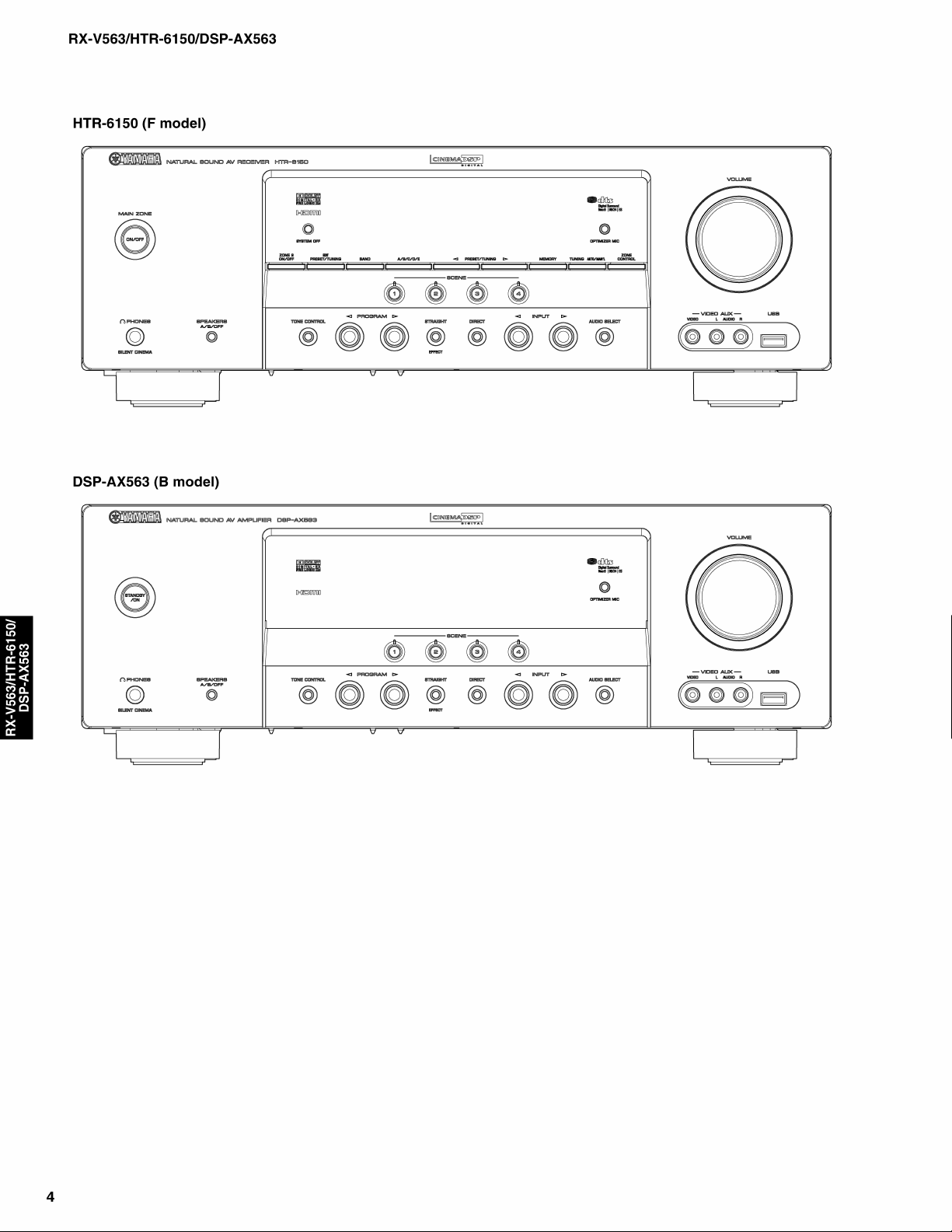
FRONT PANELS ........................................................ 3–4
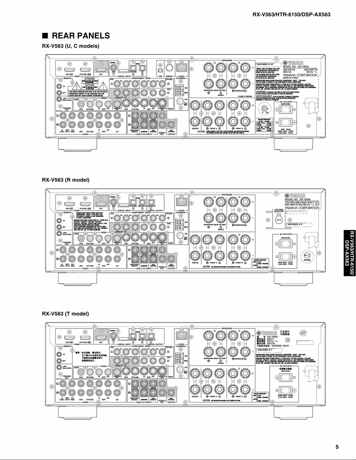
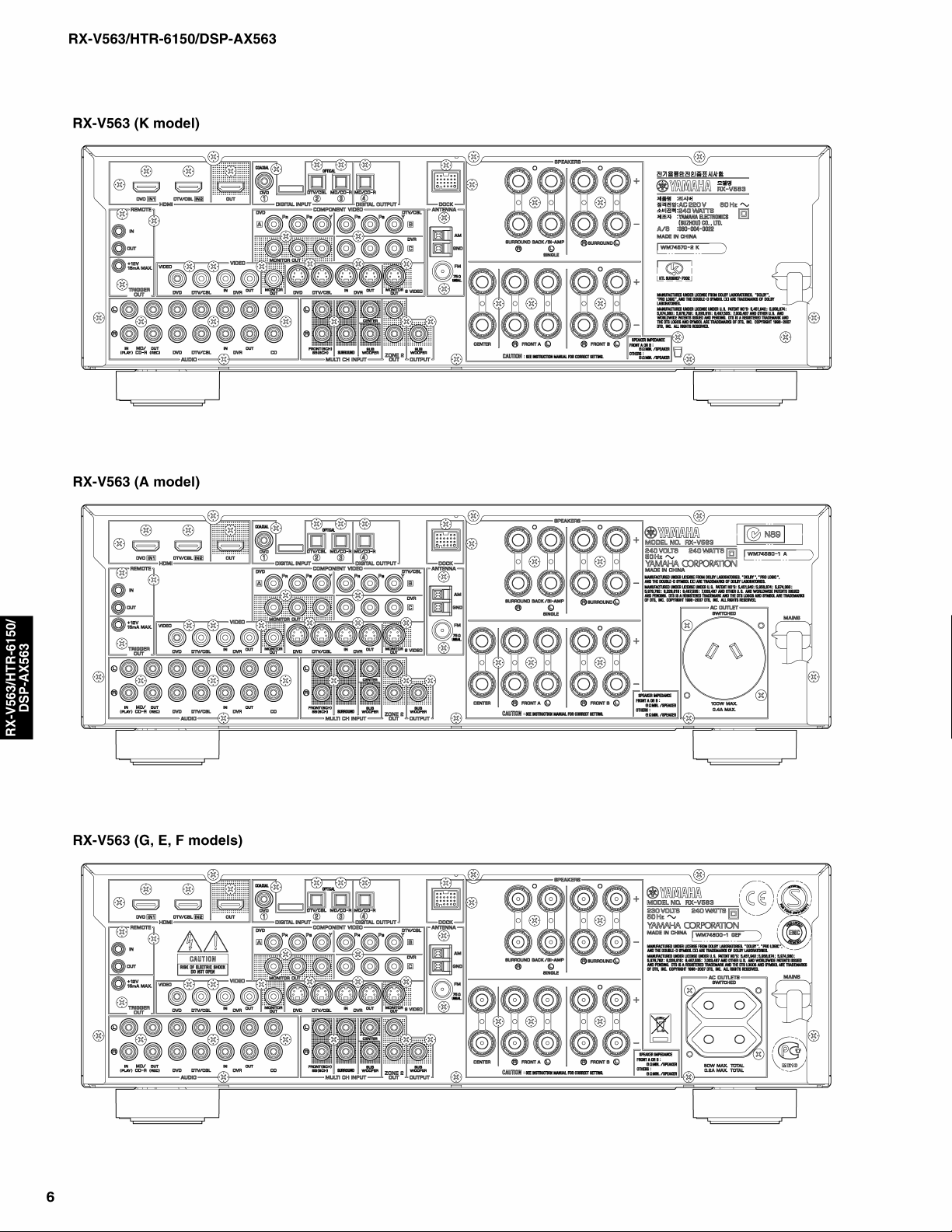
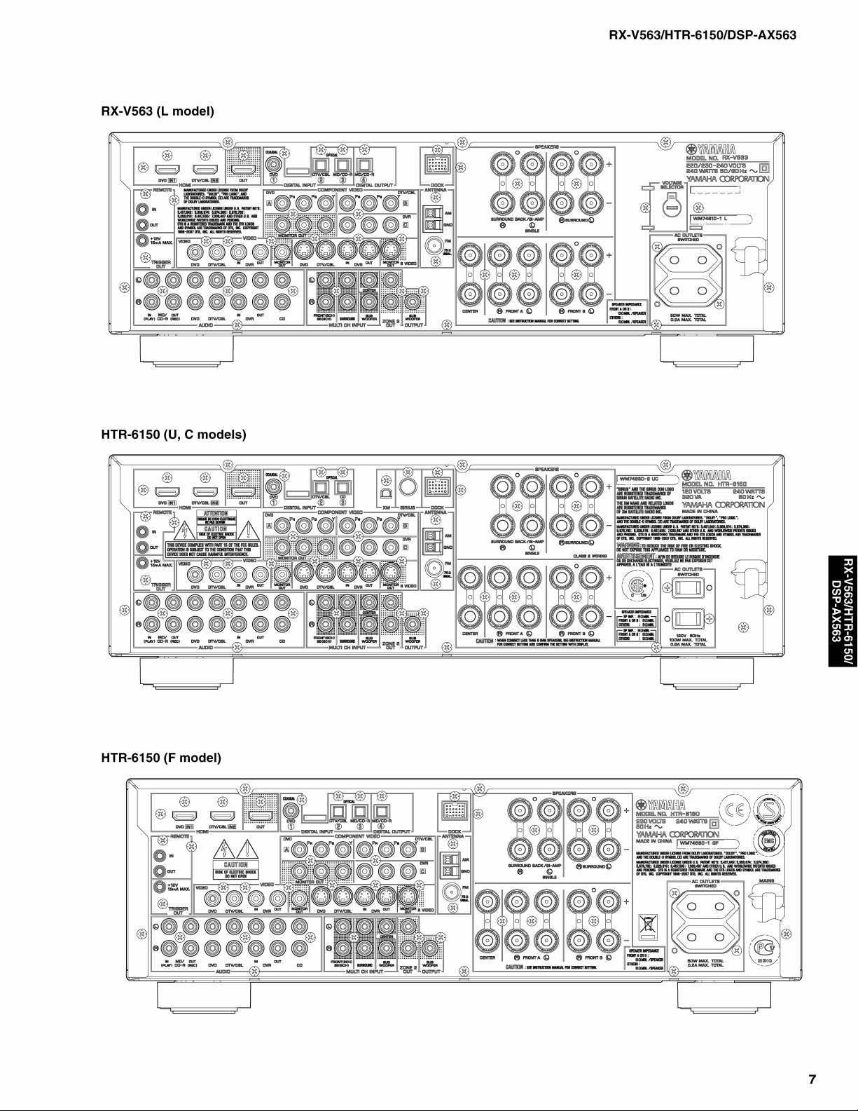
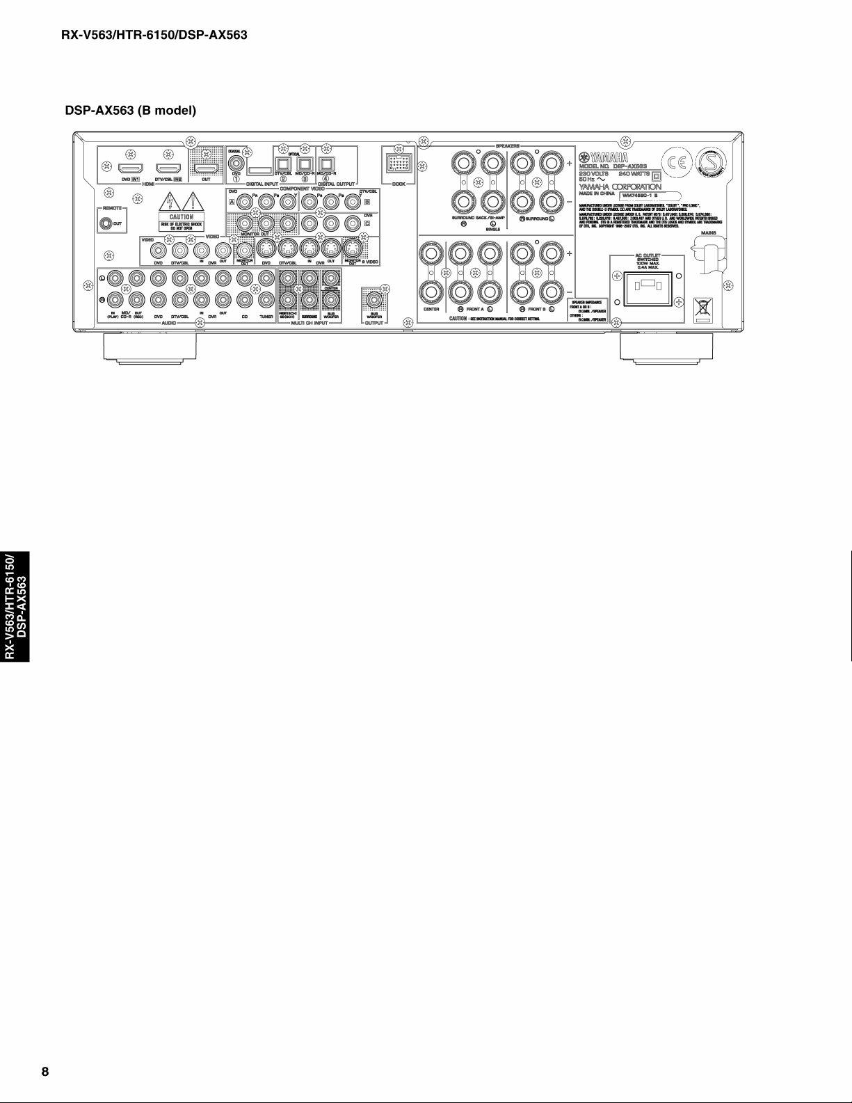
REAR PANELS .......................................................... 5–8
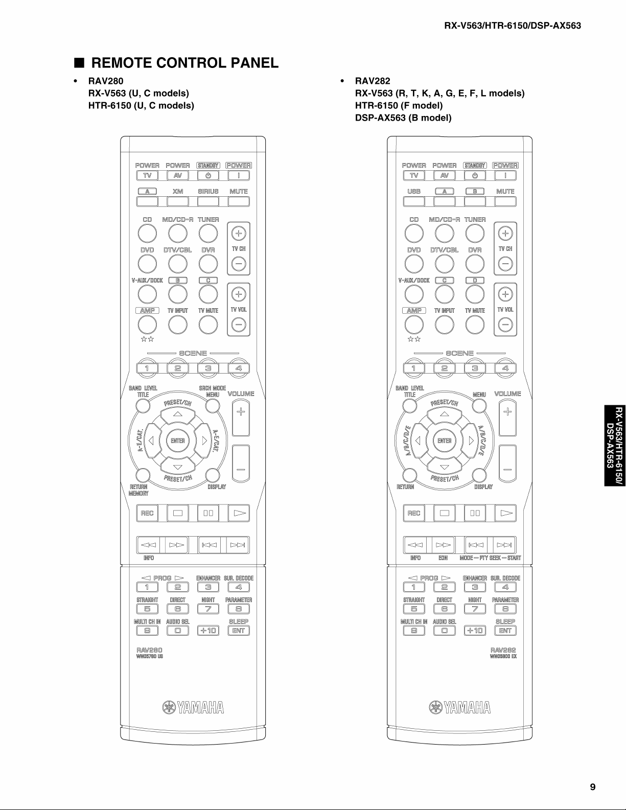
REMOTE CONTROL PANEL ........................................ 9
SPECIFICATIONS.................................................. 10–12
INTERNAL VIEW ......................................................... 13
DISASSEMBLY PROCEDURES ........................... 14–16
UPDATING FIRMWARE ........................................ 17–21
SELF DIAGNOSIS FUNCTION (DIAG) ................. 22–44
101086
2008 All rights reserved.
This manual is copyrighted by YAMAHA and may not be copied or
redistributed either in print or electronically without permission.
DISPLAY DATA ........................................................... 45
IC DATA ................................................................. 46–59
BLOCK DIAGRAMS .............................................. 61–65
PRINTED CIRCUIT BOARDS................................ 66–79
PIN CONNECTION DIAGRAMS ............................ 80–81
SCHEMATIC DIAGRAMS ...................................... 83–96
REPLACEMENT PARTS LIST ............................ 97–109
REMOTE CONTROL.......................................... 110–112
Advanced setup ......................................................... 113
P.O.Box 1, Hamamatsu, Japan
'08.03
RX-V563/HTR-6150/DSP-AX563
■ TO SERVICE PERSONNEL
1. Critical Components Information
Components having special characteristics are marked s and
must be replaced with parts having specifications equal to those
originally installed.
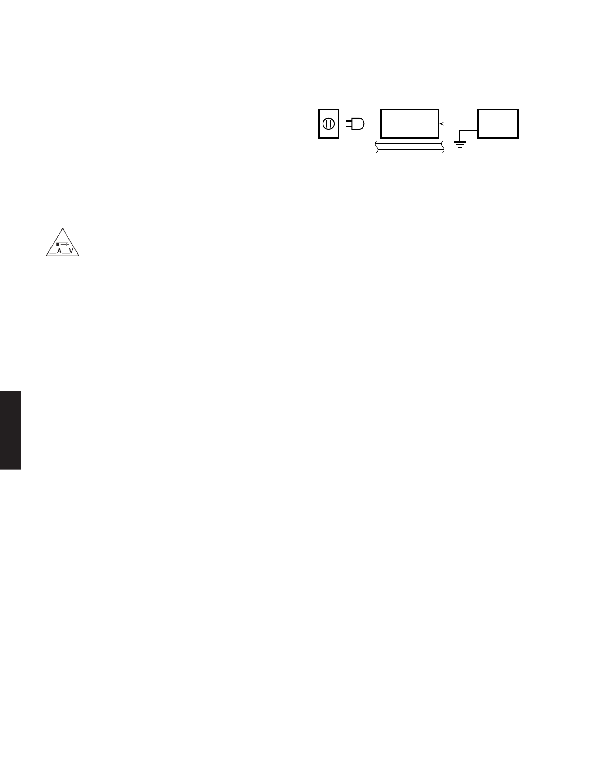
2. Leakage Current Measurement (For 120V Models Only)
When service has been completed, it is imperative to verify
that all exposed conductive surfaces are properly insulated
from supply circuits.
● Meter impedance should be equivalent to 1500 ohms shunted
by 0.15µF.
For U model
“CAUTION”
“F3401, F3402: FOR CONTINUED PROTECTION AGAINST RISK OF FIRE, REPLACE ONLY WITH SAME
TYPE 6A, 125V FUSE.”
For C model
CAUTION
F3401, F3402: REPLACE WITH SAME TYPE 6A, 125V FUSE.
ATTENTION
F3401, F3402: UTILISER UN FUSIBLE DE RECHANGE DE MÉME TYPE DE 6A, 125V.
WALL
OUTLET
● Leakage current must not exceed 0.5mA.
● Be sure to test for leakage with the AC plug in both polarities.
EQUIPMENT
UNDER TEST
INSULATING
TABLE
AC LEAKAGE
TESTER OR
EQUIVALENT
WARNING: CHEMICAL CONTENT NOTICE!
This product contains chemicals known to the State of California to cause cancer, or birth defects or other reproductive
harm.
DO NOT PLACE SOLDER, ELECTRICAL/ELECTRONIC OR PLASTIC COMPONENTS IN YOUR MOUTH FOR ANY
REASON WHAT SO EVER!
Avoid prolonged, unprotected contact between solder and your skin! When soldering, do not inhale solder fumes or expose
eyes to solder/flux vapor!
DSP-AX563
RX-V563/HTR-6150/
If you come in contact with solder or components located inside the enclosure of this product, wash your hands before
handling food.
About lead free solder
All of the P.C.B.s installed in this unit and solder joints are soldered using the lead free solder.
Among some types of lead free solder currently available, it is recommended to use one of the following types for the repair
work.
• Sn + Ag + Cu (tin + silver + copper)
• Sn + Cu (tin + copper)
• Sn + Zn + Bi (tin + zinc + bismuth)
Caution:
As the melting point temperature of the lead free solder is about 30°C to 40°C (50°F to 70°F) higher than that of the lead solder, be sure
to use a soldering iron suitable to each solder.
2


RX-V563/HTR-6150/DSP-AX563
■ SPECIFICATIONS
■ Audio Section
Minimum RMS Output Power (Power Amp. Section)
(1 kHz, 0.9 % THD)
FRONT L/R, CENTER, SURROUND L/R, SURROUND
BACK L/R
U, C models (8 ohms) .......................................... 90 W/ch
R, T, K, A, B, G, E, F, L models (6 ohms) ........... 90 W/ch
Maximum Power (JEITA) (1 kHz, 0.9 % THD, 6 ohms)
FRONT L/R, CENTER, SURROUND L/R, SURROUND
BACK L/R
R, T, K, L models ............................................... 115 W/ch
Dynamic Power Per Channel (IHF) (FRONT L/R drive)
U, C models
(8/6/4/2 ohms) ...................................... 90/110/130/150 W
R, T, K, A, B, G, E, F, L models
(6/4/2 ohms) .............................................. 100/110/125 W
Dynamic Headroom
U, C models (8 ohms) ............................................. 0.18 dB
Input Sensitivity/Input Impedance (1 kHz, 100 W / 8 ohms)
CD, etc. ............................................... 200 mV / 47 k-ohms
MULTI CH INPUT
FRONT L/R, CENTER, SURROUND L/R, SUBWOOFER
........................................................ 200 mV / 47 k-ohms
Maximum Input Signal (1 kHz, 0.5 % THD, Effect on)
CD, etc. ..........................................................2.0 V or more
Output Level/Output Impedance
REC OUT .......................................... 200 mV / 1.2 k-ohms
SUBWOOFER (2ch STEREO and FRONT SP: Small)
................................................................ 4 V / 1.2 k-ohms
Headphone Jack Rated Output/Impedance
CD, etc. (1 kHz, 200 mV, 8 ohms) ....... 400 mV / 470 ohms
Frequency Response (10 Hz to 100 kHz)
DSP-AX563
RX-V563/HTR-6150/
CD, etc. to FRONT L/R .......................................... 0 / -3 dB
Total Harmonic Distortion (1 kHz, 50 W)
Direct to FRONT L/R SP OUT
U, C models (8 ohms) ................................. 0.06 % or less
R, T, K, A, B, G, E, F, L models (6 ohms) .. 0.06 % or less
Signal to Noise Ratio (IHF-A Network)
Direct STEREO to Input shorted SP OUT
200 mV ........................................................ 98 dB or more
250 mV ...................................................... 100 dB or more
Residual Noise (IHF-A Network)
FRONT L/R SP OUT .................................... 150 µV or less
Channel Separation
CD, etc. (Input 5.1 k-ohms shorted, 1 kHz / 10 kHz)
......................................... 60 dB or more / 45 dB or more
Tone Control Characteristics
BASS
Boost/Cut ................................................ ±10 dB (100 Hz)
TREBLE
Boost/Cut ................................................ ±10 dB (20 kHz)
Filter Characteristics
FRONT, CENTER, SURROUND, SURROUND BACK small
(H.P.F.)
....... fc=40/60/80/90/100/110/120/160/200 Hz, 12 dB/oct.
SUBWOOFER (L.P.F.)
....... fc=40/60/80/90/100/110/120/160/200 Hz, 24 dB/oct.
■ Video Section
Video Signal Type
Gray back
U, C, R, K models .................................................... NTSC
T, A, B, G, E, F, L models .......................................... PAL
Video conversion
......................................................................... NTSC/PAL
Composite Video Signal Level
.................................................................. 1 Vp-p / 75 ohms
S-Video Signal Level
Y ............................................................... 1 Vp-p / 75 ohms
C ........................................................ 0.286 Vp-p / 75 ohms
Component Signal Level
Y ............................................................... 1 Vp-p / 75 ohms
Pb/Pr...................................................... 0.7 Vp-p / 75 ohms
Video Maximum Input Level
.................................................................. 1.5 Vp-p or more
Signal to Noise Ratio
....................................................................... 50 dB or more
Monitor Out Frequency Response
Component video signal .................. 5 Hz to 60 MHz, -3 dB
HDMI ........................................................................ Ver. 1.2a
■ FM Section [U, C, R, T, K, A, G, E, F, L models]
Tuning Range
U, C models............................................ 87.5 to 107.9 MHz
R, L models ............... 87.5 to 108.0 / 87.50 to 108.00 MHz
T, K, A, G, E, F models ...................... 87.50 to 108.00 MHz
50dB Quieting Sensitivity (IHF) (1 kHz, 100 % Mod.)
Mono......................................................... 2.8 µV (20.2 dBf)
Signal to Noise Ratio (IHF)
Mono / Stereo ................................................. 73 dB / 70 dB
Harmonic Distortion (1 kHz)
Mono / Stereo ................................................. 0.5 % / 0.5 %
Antenna Input .................................... 75 ohms unbalanced
■ AM Section [U, C, R, T, K, A, G, E, F, L models]
Tuning Range
U, C models.............................................. 530 to 1,710 kHz
R, L models ....................... 530 to 1,710 / 531 to 1,611 kHz
T, K, A, G, E, F models ............................ 531 to 1,611 kHz
Antenna Input .................................................Loop antenna
■ General
Power Supply
U, C models............................................... AC 120 V, 60 Hz
R model ................. AC 110, 120/220, 230-240 V, 50/60 Hz
T model ..................................................... AC 220 V, 50 Hz
K model ..................................................... AC 220 V, 60 Hz
A model ..................................................... AC 240 V, 50 Hz
B, G, E, F models ...................................... AC 230 V, 50 Hz
L model ................................. AC 220, 230-240 V, 50/60 Hz
Power Consumption
U, C models................................................ 240 W / 320 VA
R model .................................................................... 260 W
T, K, A, B, G, E, F, L models .................................... 240 W
10
Standby Power Consumption (reference data)
U, C, T, K, A, B, G, E, F models ................................ 0.8 W
Maximum Power Consumption (5ch drive, 10 % THD)
R, L models ............................................................... 490 W
AC Outlets
2 switched outlets
U, C models ........................................... 100 W max. total
R, T, G, E, F, L models ............................ 50 W max. total
1 switched outlet
A, B models.................................................... 100 W max.
Dimensions (W x H x D)
..... 435 x 151 x 351.6 mm (17-1/8" x 5-15/16" x 13-13/16")
Weight .................................................9.0 kg (19 lbs. 13 oz.)
Finish
[RX-V563]
Gold color ....................................................... R, T models
Black color .............................. U, C, R, A, G, E, F models
Titanium color ................................... K, G, E, F, L models
Silver color ......................................................A, L models
[HTR-6150]
Black color ................................................ U, C, F models
Silver color ............................................................ F model
[DSP-AX563]
Black color ........................................................... B model
Titanium color ...................................................... B model
Accessories ............................................ Remote control x 1
Batteries (R03, AAA, UM-4) x 2
Indoor FM antenna x 1 (U, C, R, T, K, A, G, E, F, L models)
AM loop antenna x 1 (U, C, R, T, K, A, G, E, F, L models)
Optimizer microphone x 1
* Specifications are subject to change without notice due to
product improvements.
※ 参考仕様および外観は予告なく変更されることがありま
す。
U .......... U.S.A. model
C .......... Canadian model
R .......... General model
T .......... Chinese model
K .......... Korean model
A .......... Australian model
Manufactured under license from Dolby Laboratories.
“Dolby”, “Pro Logic”, and the double-D symbol are trademarks of
Dolby Laboratories.
“SILENT CINEMA” is a trademark of YAMAHA CORPORATION.
B .......... British model
G .......... European model
E .......... South European model
F .......... Russian model
L .......... Singapore model
Bluetooth is a registered trademark of the Bluetooth SIG and is used
by Yamaha in accordance with a license agreement.
“HDMI”, the “HDMI” logo and “High-Definition Multimedia Interface”
are trademarks or registered trademarks of HDMI Licensing LLC.
DTS-ES | NEO:6 | 96/24. Product “DTS” and “DTS-ES | NEO:6” are
registered trademarks of DTS, Inc.
“96/24” is a trademark of DTS, Inc.
The XM name and related logos are registered trademarks of XM
Satellite Radio Inc.
Neural Surround™ name and related logos are trademarks owned by
Neural Audio Corporation.
©2006 SIRIUS Satellite Radio Inc. “SIRIUS”, “Sirius Connect”, the
SIRIUS dog logo, channel names and logos are trademarks of
SIRIUS Satellite Radio Inc.
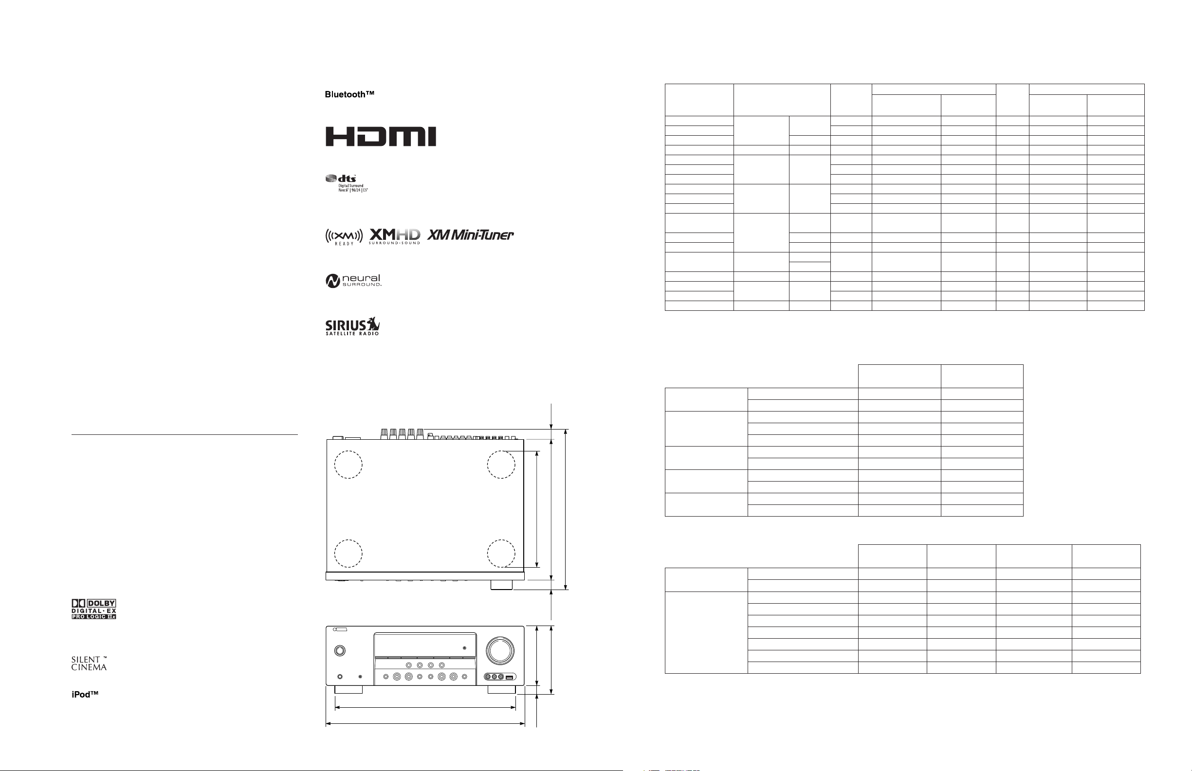
• DIMENSIONS
255 (10-1/16")
130 (5-1/8")
21.7
(7/8")
308.9 (12-1/8")
351.6 (13-13/16")
21
(13/16")
151 (5-15/16")
• SCENE TEMPLATE
DVD Viewing
DVD Movie Viewing
DVD Live Viewing
DVR Viewing
Disc Hi-fi Listening
Music Disc Listening
Disc Listening
CD Hi-fi Listening
CD Listening
CD Music Listening
Radio Listening
XM Listening
SIRIUS Listening
Dock Listening
USB Audio Listening
TV Viewing
TV Sports Viewing
Game Playing
DVD
DVR
DVD-Audio /
SA-CD / CD
CD
TUNER/RADIO
DAP
TV
GAME
Movie
Music Live
Music Disc
Music Disc
FM/AM
XM
SIRIUS
iPod
Bluetooth
USB
• SOUND/SURROUND SELECT MENU
Sound Field Parameters
STEREO
MUSIC
ENTERTAIN
MOVIE
MUSIC ENHANCER
2ch Stereo
7ch Stereo
Pop/Rock
Hall
Jazz
Game
TV Sports
Movie Spacious
Movie Dramatic
Music Enh. 2ch
Music Enh. 7ch
Surround Decoders
DECODING
FORMAT
POST DECODING
FORMAT
Dolby Digital
DTS
Dolby Pro Logic
Dolby Pro Logic IIx, II Music
Dolby Pro Logic IIx, II Movie
Dolby Pro Logic IIx, II Game
Neo:6 Cinema
Neo:6 Music
Neural Surround (U, C models)
DVD
DVD
DVD
DVR
DVD
DVD
DVD
CD
CD
CD
FM/AM
(TUNER)
XM
SIRIUS
DOCK
(V-AUX)
USB
DTV/CBL
DTV/CBL
V-A UX
RX-V563/HTR-6150/DSP-AX563
Program
Mode Sub-mode
STRAIGHT
MOVIE
MUSIC
MOVIE
DIRECT STEREO
STEREO
STEREO
DIRECT STEREO
STEREO
STEREO
MUSIC ENHANCER
MUSIC ENHANCER
MUSIC ENHANCER
MUSIC ENHANCER
MUSIC ENHANCER
STRAIGHT
ENTERTAINMENT
ENTERTAINMENT
DSP LEVEL
MIN, [MID], MAX
–
Movie Dramatic
Pop/Rock
Movie Dramatic
–
2ch Stereo
7ch Stereo
–
7ch Stereo
2ch Stereo
7ch Enhancer
7ch Enhancer
7ch Enhancer
7ch Enhancer
7ch Enhancer
–
TV Sports
Game
MUSIC ENHANCER
LOW, [HIGH]
O
O
O
O
O
O
O
PANORAMA
ON, [OFF]
DIMENSION
-3, [STD], +3
OO O
NIGHTContentsSCENE name Source
SYSTEM
SYSTEM
SYSTEM
SYSTEM
SYSTEM
SYSTEM
SYSTEM
SYSTEM
SYSTEM
SYSTEM
SYSTEM
SYSTEM
SYSTEM
SYSTEM
SYSTEM
SYSTEM
SYSTEM
SYSTEM
O
O
CENTER WIDTH
0, 1, 2, [3], 4, 5, 6, 7
U, C models
O (SCENE 1)
O (SCENE 2)
O (SCENE 4)
O (SCENE 3)
Select (Default)
R, T, K, A, B, G,
E, F, L models
O
O
O
O
O
O
O
O
O
O
O
–
O
O
O (SCENE 1)
O (SCENE 2)
O (SCENE 4)
O (SCENE 3)
CENTER IMAGE
0.0, [0.3], 1.0
O
O
O
O
O
O
O
O
–
–
O
O
O
O
O
“iPod” is a trademark of Apple, Inc., registered in the U.S. and other
countries.
395 (15-9/16")
435 (17-1/8")
21
(13/16")
Unit: mm (inch)
11
RX-V563/HTR-6150/DSP-AX563
VALUE [INITIAL]
Marks/ # * + , - . / : < > ?
[FRONT] / ZONE B
SMALL / [LARGE]
SELECT MENU
FRONT B FRONT
FRONT LARGE
CENTER SMALL
A) SPEAKER SET
NONE / [SMALL] / LARGE
NONE / SMLx1 / [SMLx2] / LRGx1 / LRGx2
SWFR / FRONT / [BOTH]
40 / 60 / [80] / 90 / 100 / 110 / 120 / 160 / 200 Hz
SUR. LR SMALL
SUR. B LR SMLx2
[NRM (normal)] / REV (reverse)
BASS OUT BOTH
CROSSOVER 80 Hz
SWFR PHASE NRM
FL • • • • • || • • • • •
B) SP LEVEL
-10 to +10 dB, [0 dB], 1 dB step
FR • • • • • || • • • • •
C • • • • • || • • • • •
SWFR • • • • • || • • • • •
SUR. L • • • • • || • • • • •
SUR. R • • • • • || • • • • •
feet / meters
1.0 to 80.0 ft, [10.0 ft], 0.5 ft step
SBL • • • • • || • • • • •
SBR • • • • • || • • • • •
UNIT feet
FRONT L 10.0 ft
FRONT R 10.0 ft
C) SP DISTANCE
1.0 to 80.0 ft, [8.5 ft], 0.5 ft step
1.0 to 80.0 ft, [10.0 ft], 0.5 ft step
CENTER 8.5 ft
1.0 to 80.0 ft, [8.0 ft], 0.5 ft step
SWFR 10.0 ft
SUR. L 8.0 ft
SUR. R 8.0 ft
UNIT: feet
0.30 to 24.00 m, [3.00 m], 0.10 m step
0.30 to 24.00 m, [2.60 m], 0.10 m step
0.30 to 24.00 m, [3.00 m], 0.10 m step
SB L 8.0 ft
SB R 8.0 ft
FRONT L 3.00 m
FRONT R 3.00 m
CENTER 2.60 m
SWFR 3.00 m
0.30 to 24.00 m, [2.40 m], 0.10 m step
SUR. L 2.40 m
SUR. R 2.40 m
SB L 2.40 m
UNIT: meters
[OFF] / ON
SB R 2.40 m
TEST TONE OFF
D) CENTER GEQ
-6.0 dB to +6.0 dB, [0 dB], 0.5 dB step
100 Hz - - || - - 0 dB
300 Hz - - || - - 0 dB
1 kHz - - || - - 0 dB
3 kHz - - || - - 0 dB
-20 dB to 0 dB, [0 dB], 1 dB step
MIN / STD / [MAX]
[FULL] / -20 dB
0 to 160 ms, [0 ms], 1 ms step
+16 dB / +10 to -30 dB, [+16 dB], 5 dB step
OFF / MUTE / -80 to +16 dB, [OFF], 1 dB step
10 kHz - - || - - 0 dB
SP LFE 0 dB
HP LFE 0 dB
SP D. R MAX
HP D. R MAX
MUTE TYP FULL
A. DELAY 0 ms
MAX VOL. +16 dB
INI. VOL. OFF
E) LFE LEVEL
F) D. RANGE
G) AUDIO SET
Input is possible to 8 characters
[RX-V563 / HTR-6150 / DSP-AX563] / OTHER
[AUTO] / LAST
[AUTO] / PLIIxMovie / PLIIxMusic / EX/ES / OFF
CD / MD/CD-R / [DVD] / DTV/CBL / V-AUX / DVR / TUNER (B model)
CD / MD/CD-R / DVD / [DTV/CBL] / V-AUX / DVR / TUNER (B model)
[CD] / MD/CD-R / DVD / DTV/CBL / V-AUX / DVR / TUNER (B model)
[DVD] / DTV/CBL / V-AUX / DVR
DVD / [DTV/CBL] / V-AUX / DVR
S. AUDIO
>AUTO LAST
EXTD AUTO
IN (1) [COAXIAL] DVD
IN (2) [OPTICAL] DTV/CBL
IN (3) [OPTICAL] CD
HDMI1 DVD
HDMI2 DTV/CBL
H) HDMI SET
I) EXTD SUR.
A) INPUT ASSIGN
Input possible Character type: Capital/ A to Z, Small/ a to z, Figure/ 0 to 9, Space,
CD / MD/CD-R / DVD / DTV/CBL / V-AUX / DVR
B) INPUT RENAME
CD / MD/CD-R / TUNER / DVD / DTV/CBL / V-AUX / DVR / DOCK / USB (X, X models) /
MULTI CH / XM (U, C models) / SIRIUS (U, C models)
C) VOLUME TRIM
-6.0 to +6.0 dB, [0.0 dB], 1.0 dB step
[AUTO] / LAST
[AUTO] / DTS
DVD / DTV/CBL / V-AUX / DVR / [LAST]
[6CH] / 8CH
[DVD] / DTV/CBL / DVR / V-AUX
* Setting is possible only when 8ch is selected using “INPUT CH”.
-4 to 0, [0], 1 step
[ON] / OFF
[CONT] / ONCE
-5 (upward) to +5 (downward), [0], 1step
CD / DTV/CBL / V-AUX
BGV LAST
INPUT CH 6CH
FRONT DVD
DIMMER 0
VIDEO CONV. ON
FL SCROLL CONT
OSD SHIFT 0
D) DECODER MODE
E) MULTI CH SET
A) DISPLAY SET
ON / 10s / [30s]
ON / 10s / [30s]
[OFF] / ON
[AUTO] / LAST
[NO] / YES
OSD-SOURCE 30s
OSD-AMP 30s
MEMORY GUARD OFF
>AUTO LAST
B) MEMORY GUARD
C) AUDIO SELECT
D) PARAM. INI
NONE / 0 to 100 %
[OFF] / SINGLE / ALL
[OFF] / ON
Analog / – – – / – – – / – – – / – – – / – – – / – – –
XM ANT.
PARENTAL LOCK
REPEAT OFF
SHUFFLE OFF
E) BLUETOOTH SET
F) XM RADIO SET
G) SIRIUS SET
FORMAT (Signal format)
F) USB PLAY STYLE
3/2/0.1 (front/surround/LFE)
DTS, Dolby Digital, or PCM
(HDMI –> DVI)
(1080p –> 1080p)
DEVICE OVER / HDCP ERROR / OUT OF RES.
SAMPLING
CHANNEL
BITRATE
FLAG
HDMI SIGNAL
HDMI RES.
HDMI ERROR (HDMI MESSAGE)
MAIN MENU SUB MENU
CATEGORY
• SET MENU TABLE
12
Use this feature to automatically adjust speaker and system parameters.
1 SOUND MENU
AUTO SETUP
MANUAL SETUP
2 INPUT MENU
3 OPTION MENU
(U, C models)
E, F, L models)
(R, T, K, A, B, G,
AUDIO
SIGNAL INFO
VIDEO
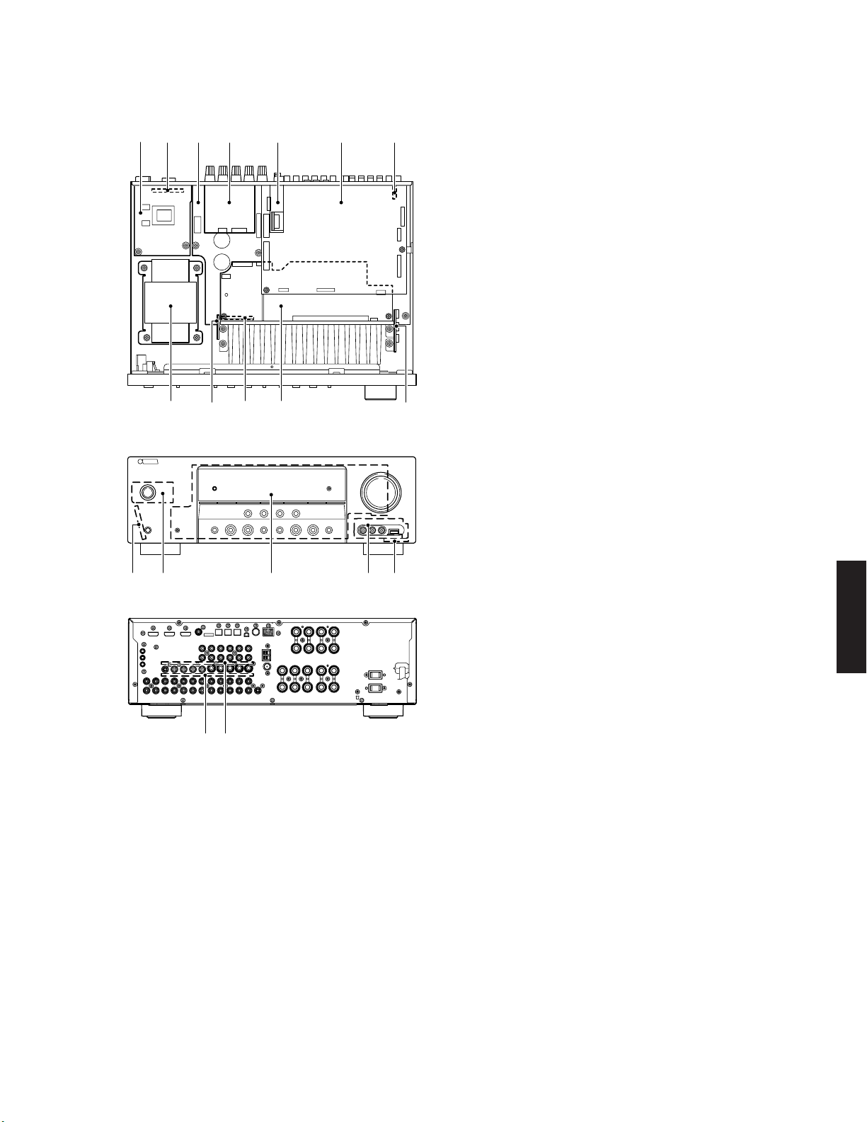
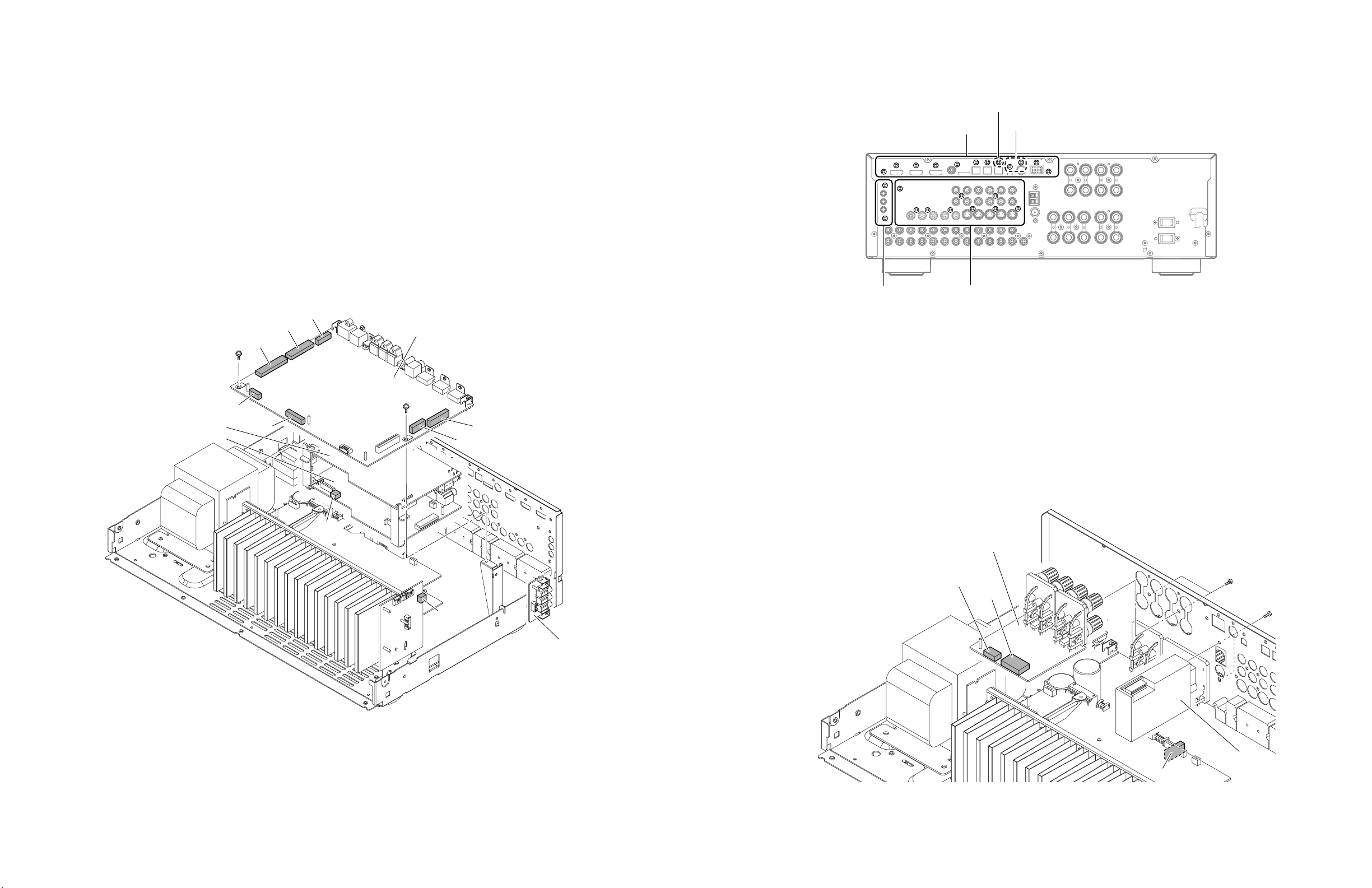
■ INTERNAL VIEW
• Top view
4
1
• Front view
32 5 6 7
B 0 9
RX-V563/HTR-6150/DSP-AX563
1
VIDEO (3) P.C.B.
2
VIDEO (5) P.C.B. (R, L models)
3
MAIN (1) P.C.B.
4
VIDEO (4) P.C.B.
5
Tuner
6
DSP P.C.B.
7
VIDEO (6) P.C.B.
8
OPERATION (8) P.C.B.
9
OPERATION (2) P.C.B.
0
MAIN (2) P.C.B.
A
OPERATION (9) P.C.B.
B
Power Transformer
C
OPERATION (3) P.C.B.
D
OPERATION (7) P.C.B.
E
OPERATION (1) P.C.B.
F
OPERATION (5) P.C.B. (U, C models)
8A
OPERATION (4) P.C.B. (R, T, K, A, B, G, E, F, L models)
G
OPERATION (6) P.C.B. (R, T, K, A, B, G, E, F, L models)
H
VIDEO (2) P.C.B.
I
VIDEO (1) P.C.B.
D E F G
C
• Rear view
HI
RX-V563/HTR-6150/
DSP-AX563
13
RX-V563/HTR-6150/DSP-AX563
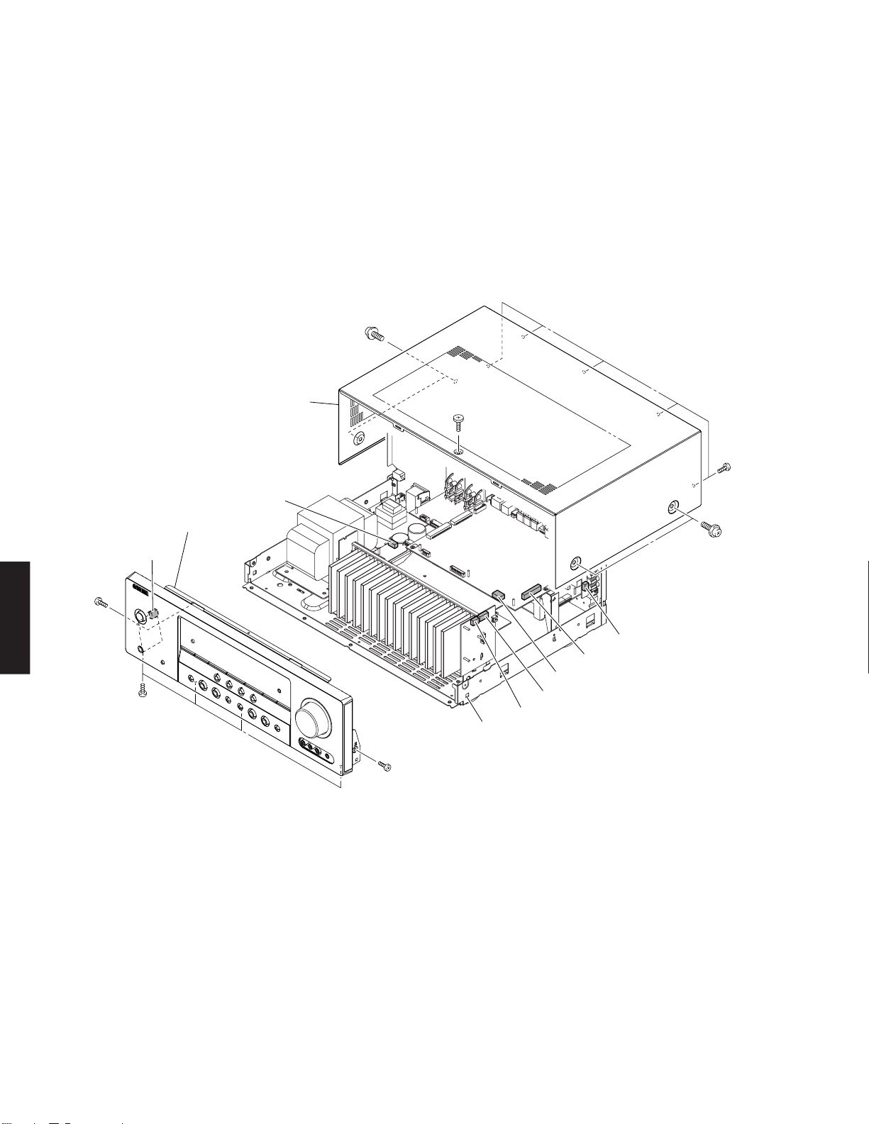
■ DISASSEMBLY PROCEDURES
(Remove parts in the order as numbered.)
Disconnect the power cable from the AC outlet.
1. Removal of Top Cover
a. Remove 5 screws (1), 4 screws (2) and 1 screw (3).
(Fig. 1)
b. Slide the top cover rearward to remove it. (Fig. 1)
2
Top cover
CB703
Front panel unit
CB601
2. Removal of Front Panel Unit
a. Remove 6 screws (4). (Fig. 1)
b. Remove CB71 (R, T, K, A, B, G, E, F, L models), CB83,
CB366, CB601, CB602, CB608 and CB703. (Fig. 1)
c. Release hook and then remove the front panel unit.
(Fig. 1)
3
1
2
4
DSP-AX563
RX-V563/HTR-6150/
CB366
CB83
CB71 (R, T, K, A, B, G, E, F, L models)
4
Hook
4
CB608
CB602
Fig. 1
14
RX-V563/HTR-6150/DSP-AX563
3. Removal of DSP P.C.B.
Note: U, C, F models
After replacement of DSP P.C.B. or writing of the
firmware, make sure to activate the self-diagnostic function and change the “M6 Model ID” setting
to the same model name as this unit (RX-V563 or
HTR-6150).
a. Remove 2 screws (5). (Fig. 2)
b. Remove 11 screws (U, C models) / 10 scrwes (R, T, K,
A, B, G, E, F, L models) (6). (Fig. 3)
c. Remove CB21, CB22, CB31, CB32, CB81, CB82 and
CB84. (Fig. 2)
d. Remove DSP P.C.B. (Fig. 2)
CB32
CB31
CB84
5
CB82
VIDEO (2) P.C.B.
VIDEO (1) P.C.B.
CB81
4. Removal of VIDEO (1), (2) and (6) P.C.B.s
a. Remove 2 screws (7). (Fig. 3)
b. Remove VIDEO (6) P.C.B. (Fig. 2)
c. Remove 9 screws (8). (Fig. 3)
d. Remove CB301 and CB609. (Fig. 2)
e. Remove VIDEO (1) and (2) P.C.B.s. (Fig. 2)
DSP P.C.B.
5
CB21
CB22
7
5. Removal of VIDEO (4) P.C.B.
a. Remove 2 screws (9). (Fig. 4)
b. Remove CB351 and CB353. (Fig. 4)
g. Remove VIDEO (4) P.C.B. (Fig. 4)
R, T, K, A, B, G, E, F, L models
6
8
U, C models
Fig. 3
6. Removal of FM/AM Tuner
a. Remove 2 screws (0). (Fig. 4)
b. Remove CB403. (Fig. 4)
c. Remove FM/AM tuner. (Fig. 4)
CB301
VIDEO (4) P.C.B.
9
CB351
CB353
0
CB609
VIDEO (6) P.C.B.
Fig. 2
FM / AM tuner
CB403
Fig. 4
15
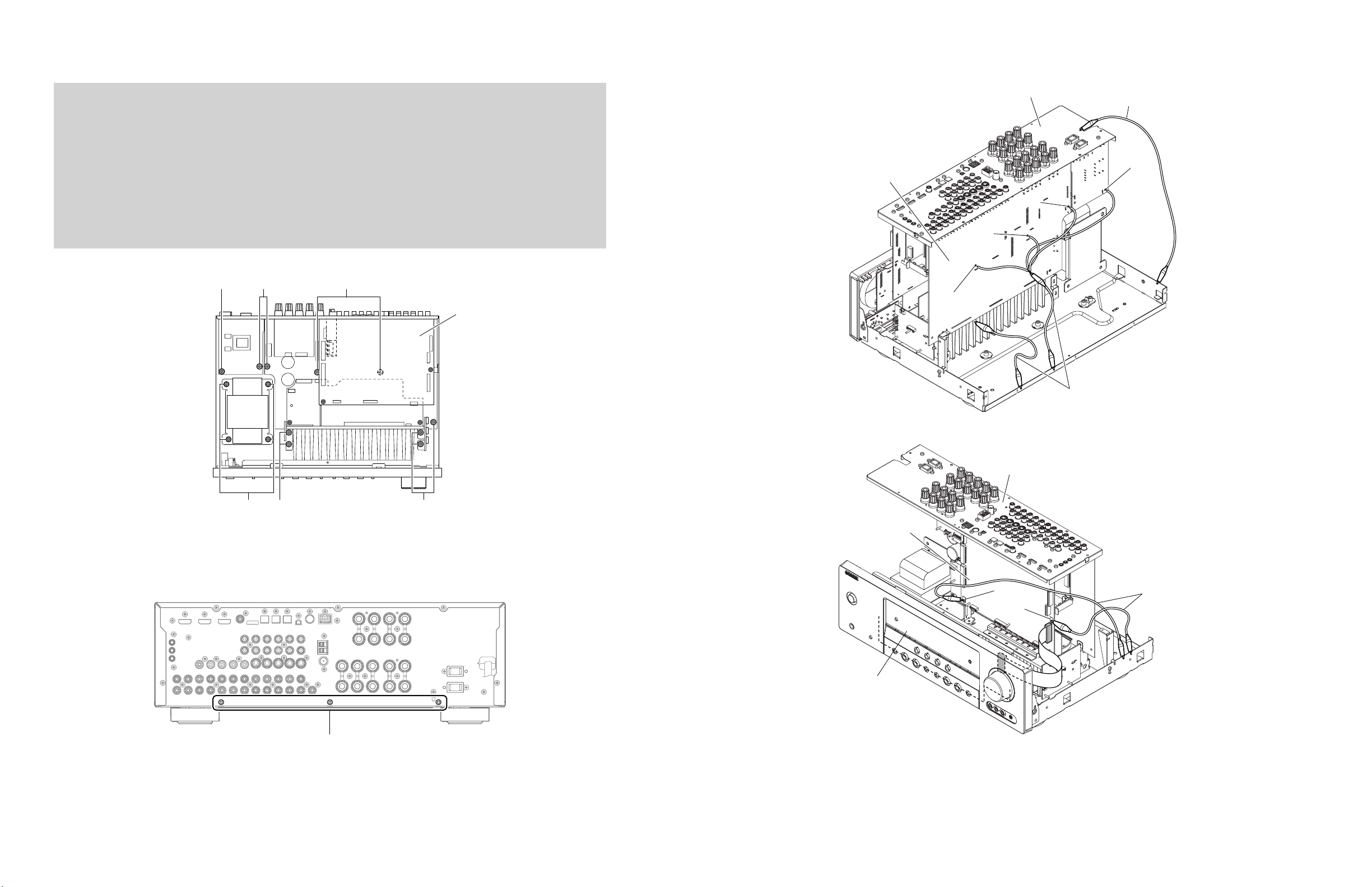
RX-V563/HTR-6150/DSP-AX563
When checking the P.C.B.:
a. Remove the top cover. (Fig. 1)
b. Remove DSP P.C.B.. (Fig. 2)
c. Remove 6 screws (A). (Fig. 5)
d. Remove 2 screws (B). (Fig. 5)
e. Remove 3 screws (C). (Fig. 6)
f. Remove 2 screws (D). (Fig. 5)
g. Remove 4 screws (E). (Fig. 5)
h. Place the P.C.B. upright. (Fig. 7)
i. The P.C.B. removed from the chassis does not work because its grounding is loose.
Be sure to connect the ground of rear panel and MAIN (1) P.C.B. (G5004, G5005, G5006 and G3401) and DSP P.C.B.
(G801 and G802) to the chassis with a ground lead or the like. (Fig. 7)
AB
D
DSP P.C.B.
Rear panel
M
A
IN
(1
) P
.C
.B
.
G5006
G5004
G5005
Ground lead
Ground lead
G3401
Rear panel
E
A
Fig. 5
C
Fig. 6
A
DSP P.C.B.
G801
G802
OPERATION (1) P.C.B.
Ground lead
Fig. 7
16
■ UPDATING FIRMWARE
Note: U, C, F models
After replacement of DSP P.C.B. or writing of the firmware, make sure to activate the self-diagnostic function and
change the “M6 Model ID” setting to the same model name as this unit (RX-V563 or HTR-6150).
After replacing the following parts, be sure to write the latest firmware.
• P.C.B. ass’y DSP P.C.B.
• IC52 FLASH ROM of DSP P.C.B.
RX-V563/HTR-6150/DSP-AX563
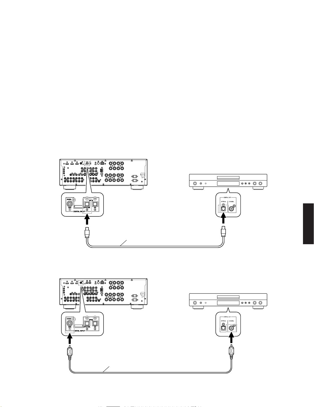
● Required Tools
• DVD or CD player (with DIGITAL OUTPUT (OPTICAL or COAXIAL) jack)
• Optical cable (when OPTICAL jack is used)
• Digital audio pin cable (when COAXIAL jack is used)
• Firmware CD
* To make the firmware CD, download the latest
firmware from the specified download source to
PC.
Example of connection between digital OPTICAL jacks
This unit
● Operation Procedures
1. Connect this unit and DVD/CD player as shown below. (Fig. 1)
DVD/CD player
RX-V563/HTR-6150/
DSP-AX563
Optical cable
Example of connection between digital COAXIAL jacks
This unit
Digital audio pin cable
DVD/CD player
Fig. 1
17
RX-V563/HTR-6150/DSP-AX563
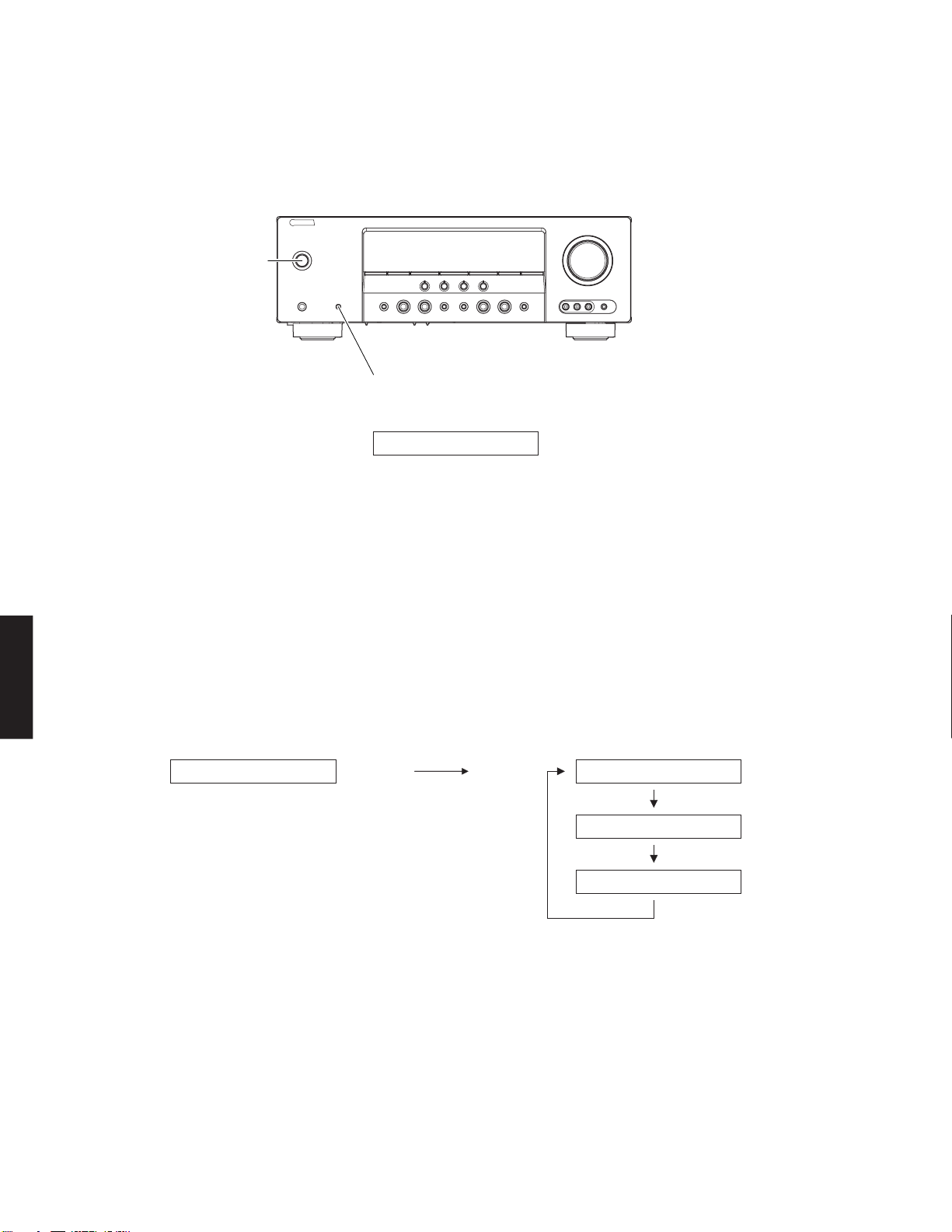
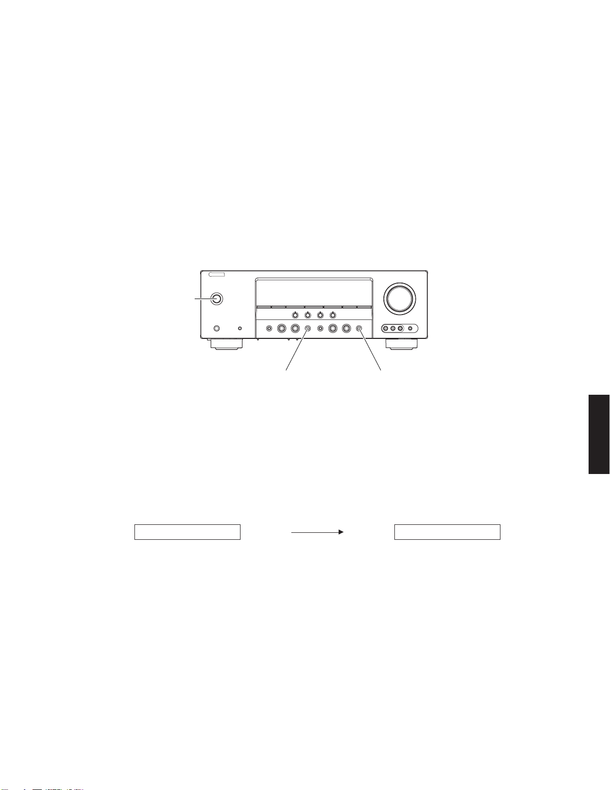
2. While simultaneously pressing the “MAIN ZONE ON/OFF” (RX-V563, HTR-6150) / “STANDBY/ON” (DSP-AX563)
and “SPEAKERS A/B/OFF” keys of this unit, connect the power cable of this unit to the AC outlet. (Fig. 2)
The FIRMWARE UPDATE mode is activated and “SPDIF Upgrade” is displayed. (Fig. 2)
"MAIN ZONE ON/OFF" key
(RX-V563, HTR-6150)
"STANDBY/ON" key
(DSP-AX563)
"SPEAKERS A/B/OFF" key
FIRMWARE UPDATE mode
SPDIF Upgrade
Fig. 2
3. Connect the power cable of DVD/CD player to the AC outlet.
4. Press the “STANDBY/ON” key of the DVD/CD player.
5. Press the “EJECT” key of the DVD/CD player to open the disc tray.
6. Place the firmware CD in the disc tray and close the disc tray.
7. Press the “PLAY” key of the DVD/CD player.
Then writing of the firmware is started. (Fig. 3)
8. When writing of the firmware is completed, “Upgrade OK”, “Please...” and “Turn off!!” are displayed repeatedly. (Fig. 3)
DSP-AX563
RX-V563/HTR-6150/
Writing is completed.Writing is started.
Address:XXXXXX Upgrade OK
XXXXXX: Address information of the received data
Please...
Turn off!!
Fig. 3
18
* When the version of the firmware to be written is the same as the one existing in this unit, “Same Version”,
“Please...” and “Turn off!!” are displayed repeatedly. (Upgrading is not necessary.)
If the display remains unchanged for more than 10 seconds after starting the firmware CD play procedure, perform the firmware CD play procedure again from the beginning.
If “FILE CORRUPTED” is displayed after “Address:XXXXXX”, make sure that the firmware CD is not corrupted
and perform steps 1 to 8 of “Operation Procedures” again.
If “Upgrade Failed” is displayed, perform Steps 1 to 8 of “Operation Procedures” again.
RX-V563/HTR-6150/DSP-AX563
9. Press the “STOP” key of the DVD/CD player.
10. Press the “EJECT” key of the DVD/CD player to open the disc tray.
11. Remove the firmware CD from the disc tray and close the disc tray.
12. Turn off the power of the DVD/CD player and disconnect the power cable from the AC outlet.
13. Turn off the power by pressing the “MAIN ZONE ON/OFF” (RX-V563, HTR-6150) / “STANDBY/ON” (DSP-AX563)
key of this unit.
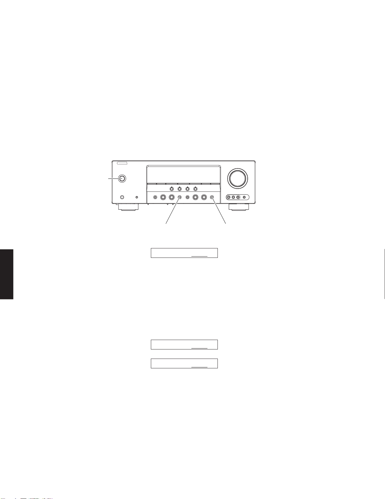
● Initializing of this unit
* After updating the firmware, be sure to initialize this unit.
1. Connect the power cable of this unit to the AC outlet.
2. Press the “MAIN ZONE ON/OFF” (RX-V563, HTR-6150) / “STANDBY/ON” (DSP-AX563) key while simultaneously
pressing the “STRAIGHT” and “AUDIO SELECT” keys. (Fig. 4)
The self-diagnostic function is activated.
"MAIN ZONE ON/OFF" key
(RX-V563, HTR-6150)
"STANDBY/ON" key
(DSP-AX563)
"STRAIGHT" key "AUDIO SELECT" key
Fig. 4
3. Select the main menu “R. FACTORY PRESET”.
4. Select the “PRESET RSRV”.
PRESET RESERVED (Initialization reserved)PRESET INHIBIT (Initialization inhibited)
R1.PRESET INHI R2.PRESET RSRV
5. Turn off the power of this unit and disconnect the power cable from the AC outlet.
RX-V563/HTR-6150/
DSP-AX563
19
RX-V563/HTR-6150/DSP-AX563
● Confirmation of firmware version and checksum
To confirm that the firmware is updated successfully, check the firmware version and checksum value by using the selfdiagnostic function menu “S. ROM VER/SUM”.
For more information, refer to “SELF-DIAGNOSTIC FUNCTION”.
* When the displayed firmware version and checksum are different from written firmware version and checksum, follow
the steps from 1 to 13 of “Operation Procedures” again.
1. Reconnect the power cable of this unit to the AC outlet.
2. Press the “MAIN ZONE ON/OFF” (RX-V563, HTR-6150) / “STANDBY/ON” (DSP-AX563) key while simultaneously
pressing the “STRAIGHT” and “AUDIO SELECT” keys. (Fig. 5)
Then the self-diagnostic function is activated.
3. Select the self-diagnostic function menu “S1. Version”.
Confirm the displayed firmware version is the same as the written firmware version. (Fig. 5)
"MAIN ZONE ON/OFF" key
(RX-V563, HTR-6150)
"STANDBY/ON" key
(DSP-AX563)
DSP-AX563
RX-V563/HTR-6150/
4. Select the self-diagnostic function menu “S2. All checksum/S3. Program checksum”.
Confirm the displayed checksum is the same as the written firmware checksum. (Fig. 6)
(The checksum value is found where downloading is specified to.)
5. Turn off the power of this unit and disconnect the power cable from the AC outlet.
"STRAIGHT" key "AUDIO SELECT" key
Example:
S1. VER. E048
Fig. 5
Example:
S2.A.SUM:EDA1
S3.P.SUM:FE77
Fig. 6
20
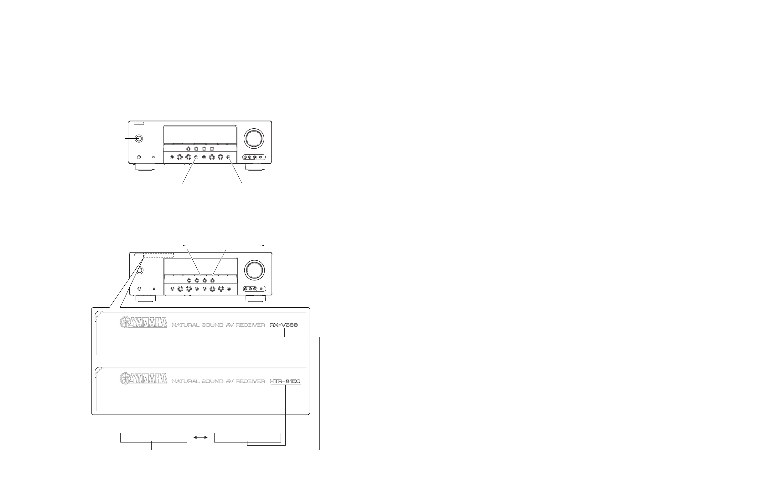
● Confirmation of model name (U, C, F models)
After replacement of DSP P.C.B. or writing of the firmware, make sure to activate the self-diagnostic function and change
the “M6 Model ID” setting to the same model name as this unit (RX-V563 or HTR-6150).
1. Connect the power cable of this unit to the AC outlet.
2. Press the “MAIN ZONE ON/OFF” (RX-V563, HTR-6150) / “STANDBY/ON” (DSP-AX563) key while simultaneously
pressing the “STRAIGHT” and “AUDIO SELECT” keys. (Fig. 7)
The self-diagnostic function is activated.
3. Select the self-diagnostic function menu “M6. Model ID”.
"MAIN ZONE ON/OFF" key
(RX-V563, HTR-6150)
"STANDBY/ON" key
(DSP-AX563)
"STRAIGHT" key "AUDIO SELECT" key
RX-V563/HTR-6150/DSP-AX563
Fig. 7
4. Press “PRESET/TUNING<” or “PRESET/TUNING>”key and select the model name.
"PRESET/TUNING " key "PRESET/TUNING " key
M6.RX-V563 M6.HTR-6150
Fig. 8
21
 Loading...