

Yamaha RX-V563 User Manual [ru]

RX-V563
AV Receive r
F
OWNER’S MANUAL
ИНСТРУКЦИЯ ПО ЭКСПЛУАТАЦИИ
CAUTION: READ THIS BEFORE OPERATING YOUR UNIT.
Caution: Read this before operating your unit.
1 To assure the finest performance, please read this manual
carefully. Keep it in a safe place for future reference.
2 Install this sound system in a well ventilated, cool, dry, clean
place – away from direct sunlight, heat sources, vibration,
dust, moisture, and/or cold. Allow ventilation space of at least
30 cm on the top, 20 cm on the left and right, and 20 cm on
the back of this unit.
3 Locate this unit away from other electrical appliances, motors,
or transformers to avoid humming sounds.
4 Do not expose this unit to sudden temperature changes from
cold to hot, and do not locate this unit in a environment with
high humidity (i.e. a room with a humidifier) to prevent
condensation inside this unit, which may cause an electrical
shock, fire, damage to this unit, and/or personal injury.
5 Avoid installing this unit where foreign object may fall onto
this unit and/or this unit may be exposed to liquid dripping or
splashing. On the top of this unit, do not place:
– other components, as they may cause damage and/or
discoloration on the surface of this unit.
– burning objects (i.e. candles), as they may cause fire,
damage to this unit, and/or personal injury.
– containers with liquid in them, as they may fall and liquid
may cause electrical shock to the user and/or damage to
this unit.
6 Do not cover this unit with a newspaper, tablecloth, curtain,
etc. in order not to obstruct heat radiation. If the temperature
inside this unit rises, it may cause fire, damage to this unit,
and/or personal injury.
7 Do not plug in this unit to a wall outlet until all connections
are complete.
8 Do not operate this unit upside-down. It may overheat,
possibly causing damage.
9 Do not use force on switches, knobs and/or cords.
10 When disconnecting the power cable from the wall outlet,
grasp the plug; do not pull the cord.
11 Do not clean this unit with chemical solvents; this might
damage the finish. Use a clean, dry cloth.
12 Only voltage specified on this unit must be used. Using this
unit with a higher voltage than specified is dangerous and may
cause fire, damage to this unit, and/or personal injury. Yamaha
will not be held responsible for any damage resulting from use
of this unit with a voltage other than specified.
13 To prevent damage by lightning, keep the power cord and
outdoor antennas disconnected from a wall outlet or the unit
during a lightning storm.
14 Do not attempt to modify or fix this unit. Contact qualified
Yamaha service personnel when any service is needed. The
cabinet should never be opened for any reasons.
15 When not planning to use this unit for long periods of time
(i.e. vacation), disconnect the AC power plug from the wall
outlet.
16 Install this unit near the AC outlet and where the AC power
plug can be reached easily.
17 Be sure to read the “Troubleshooting” section on common
operating errors before concluding that this unit is faulty.
18 Before moving this unit, press CSYSTEM OFF to set this
unit in the standby mode, and disconnect the AC power plug
from the wall outlet.
19 VOLTAGE SELECTOR (Asia and General models only)
The VOLTAGE SELECTOR on the rear panel of this unit
must be set for your local main voltage BEFORE plugging
into the AC wall outlet. Voltages are:
Asia model ............................ 220/230–240 V AC, 50/60 Hz
General model ........ 110/120/220/230–240 V AC, 50/60 Hz
20 The batteries shall not be exposed to excessive heat such as
sunshine, fire or like.
21 Excessive sound pressure from earphones and headphones can
cause hearing loss.
WARNING
TO REDUCE THE RISK OF FIRE OR ELECTRIC
SHOCK, DO NOT EXPOSE THIS UNIT TO RAIN
OR MOISTURE.
This unit is not disconnected from the AC power
source as long as it is connected to the wall outlet, even
if this unit itself is turned off by
CSYSTEM OFF. This
state is called the standby mode. In this state, this unit
is designed to consume a very small quantity of power.
■ For U.K. customers
If the socket outlets in the home are not suitable for the
plug supplied with this appliance, it should be cut off and
an appropriate 3 pin plug fitted. For details, refer to the
instructions described below.
Note
The plug severed from the mains lead must be destroyed, as a
plug with bared flexible cord is hazardous if engaged in a live
socket outlet.
■ Special Instructions for U.K. Model
IMPORTANT
THE WIRES IN MAINS LEAD ARE COLOURED IN
ACCORDANCE WITH THE FOLLOWING CODE:
Blue: NEUTRAL
Brown: LIVE
As the colours of the wires in the mains lead of this apparatus
may not correspond with the coloured markings identifying
the terminals in your plug, proceed as follows:
The wire which is coloured BLUE must be connected to the
terminal which is marked with the letter N or coloured
BLACK. The wire which is coloured BROWN must be
connected to the terminal which is marked with the letter L or
coloured RED.
Making sure that neither core is connected to the earth
terminal of the three pin plug.
This symbol mark is according to the
EU directive 2002/96/EC.
This symbol mark means that electrical
and electronic equipment, at their endof-life, should be disposed of separately
from your household waste.
Please act according to your local rules
and do not dispose of your old products
with your normal household waste.
En

Contents
INTRODUCTION
Features ................................................................... 2
Getting started ........................................................ 3
Quick start guide .................................................... 4
Preparation: Check the items ..................................... 4
Step 1: Set up your speakers ...................................... 5
Step 2: Connect your DVD player and other
components............................................................ 6
Step 3: Press SCENE 1 button................................... 7
What do you want to do with this unit? ..................... 8
PREPARATION
Connections ............................................................. 9
Rear panel .................................................................. 9
Placing speakers....................................................... 10
Connecting speakers ................................................ 11
Information on jacks and cable plugs ...................... 13
Information on HDMI™.......................................... 14
Audio and video signal flow.................................... 15
Connecting video components................................. 16
Connecting other components ................................. 17
Connecting audio components................................. 19
Connecting a Yamaha iPod™ universal dock or
Bluetooth™ adapter............................................. 20
Using REMOTE IN/OUT jacks............................... 20
Using the VIDEO AUX jacks on the front panel .... 21
Connecting the FM and AM antennas ..................... 21
Connecting the power cable..................................... 22
Turning on and off the power .................................. 23
Front panel display .................................................. 24
Optimizing the speaker setting
for your listening room .................................... 26
Using AUTO SETUP .............................................. 26
BASIC OPERATION
Selecting the SCENE templates........................... 30
Selecting the desired SCENE template.................... 30
Creating your original SCENE templates................ 33
Using remote control on the SCENE feature........... 34
Playback ................................................................ 35
Basic operations....................................................... 35
Selecting audio input jacks
(AUDIO SELECT).............................................. 36
Selecting the MULTI CH INPUT component......... 36
Displaying the current status of this unit
on a video monitor............................................... 37
Using your headphones............................................ 37
Muting the audio output........................................... 37
Playing video sources in the background
of an audio source................................................ 38
Displaying the input source information ................. 38
Using the sleep timer ............................................... 39
Sound field programs ........................................... 40
Sound field program descriptions ............................ 40
Using audio features ............................................. 43
Enjoying high quality sound.................................... 43
Adjusting the tonal quality....................................... 43
Adjusting the speaker level...................................... 43
Selecting the night listening mode........................... 44
FM/AM tuning ...................................................... 45
Automatic tuning ..................................................... 45
Manual tuning.......................................................... 45
Automatic preset tuning........................................... 46
Manual preset tuning ............................................... 46
Selecting preset stations........................................... 47
Exchanging preset station ........................................ 47
Radio Data System tuning
(Europe and Russia models only) ....................48
Displaying the Radio Data System information ...... 48
Selecting the Radio Data System program type
(PTY SEEK mode).............................................. 49
Using the enhanced other networks (EON) data
service.................................................................. 50
Using a USB memory device or a USB portable
audio player .......................................................51
Playback operation .................................................. 51
Using iPod™ ..........................................................53
Controlling iPod™................................................... 53
Using Bluetooth™ components ............................55
Pairing the Bluetooth™ adapter and your
Bluetooth™ component....................................... 55
Playback of the Bluetooth™ component ................. 55
Recording ...............................................................56
ADVANCED OPERATION
SET MENU ............................................................57
Using SET MENU................................................... 58
1 SOUND MENU.................................................... 59
2 INPUT MENU...................................................... 65
3 OPTION MENU................................................... 67
Remote control features........................................71
Controlling this unit, a TV, or other components.... 71
Setting remote control codes ................................... 73
Using multi-zone configuration............................74
Connecting Zone 2................................................... 74
Controlling Zone 2................................................... 75
Advanced setup......................................................77
ADDITIONAL INFORMATION
Troubleshooting.....................................................78
Glossary..................................................................88
Specifications .........................................................91
Index .......................................................................92
APPENDIX
(at the end of this manual)
Front panel................................................................i
Remote control ....................................................... ii
List of remote control codes ................................. iii
About this manual
• y indicates a tip for your operation.
• Some operations can be performed by using either the buttons on the
front panel or the ones on the remote control. In case the button
names differ between the front panel and the remote control, the
button name on the remote control is given in parentheses.
• This manual is printed prior to production. Design and specifications
are subject to change in part as a result of improvements, etc. In case
of differences between the manual and product, the product has
priority.
•“MSPEAKERS” or “3DVD” (example) indicates the name of the
parts on the front panel or the remote control. Refer to the attached
sheet or the pages at the end of this manual for the information about
each position of the parts.
• The symbol “☞ ” with page number(s) indicates the corresponding
reference page(s).
PREPARATIONINTRODUCTION
OPERATION
BASIC
OPERATION
ADVANCED
INFORMATION
ADDITIONAL
APPENDIX
English
1 En

Features
Features
Built-in 7-channel power amplifier
◆ Minimum RMS output power
[U.S.A. and Canada models]
(1 kHz, 0.9% THD, 8 Ω)
90 W/ch
[Other models]
(1 kHz, 0.9% THD, 6 Ω)
90 W/ch
SCENE select function
◆ Preset SCENE templates for various situations
◆ SCENE template customizing capability
Decoders and DSP circuits
◆ Proprietary Yamaha technology for the creation of
multi-channel surround sound
◆ Compressed Music Enhancer mode
◆ Dolby Digital/Dolby Digital EX decoder
◆ DTS/DTS-ES Matrix, Discrete, DTS Neo:6,
DTS 96/24 decoder
◆ Dolby Pro Logic/Dolby Pro Logic II/Dolby Pro Logic IIx
decoder
◆ Virtual CINEMA DSP
◆ SILENT CINEMA
™
Radio tuners
◆ FM/AM tuning capability
◆ Radio Data System capability (Europe model only)
HDMI (High-Definition Multimedia Interface)
◆ HDMI interface for standard, enhanced or high-definition
video (includes 1080p video signal transmission) as well as
multi-channel digital audio
DOCK terminal
◆ DOCK terminal to connect a Yamaha iPod universal dock
(such as YDS-10, sold separately) or Bluetooth adapter (such
as YBA-10, sold separately).
USB features
◆ USB port to connect a USB memory device or a USB portable
audio player
◆ MP3, WMA and WAV capability
Other features
◆ YPAO (Yamaha Parametric Room Acoustic Optimizer) for
automatic speaker setup
◆ 192-kHz/24-bit D/A converter
◆ DIRECT mode for high quality sound for all sources
◆ 6 additional input jacks for discrete multi-channel input
◆ OSD (on-screen display) menus that allow you to optimize
this unit to suit your individual audiovisual system
◆ Component video input/output capability
(3 COMPONENT VIDEO INs and 1 MONITOR OUT)
◆ S-video signal input/output capability
◆ Optical and coaxial digital audio signal jacks
◆ Sleep timer
◆ Cinema and music night listening modes
◆ iPod controlling capability
◆ Remote control with preset remote control codes
◆ Zone 2 custom installation facility
◆ Bi-amplification connection capability
Manufactured under license from Dolby Laboratories.
“Dolby”, “Pro Logic”, and the double-D symbol are trademarks
of Dolby Laboratories.
“SILENT CINEMA” is a trademark of Yamaha Corporation.
iPod™
“iPod” is a trademark of Apple, Inc., registered in the U.S. and
other countries.
DTS-ES | NEO:6 | 96/24. Product “DTS” and “DTS-ES | NEO:6”
are registered trademarks of DTS, Inc.
“96/24” is a trademark of DTS, Inc.
Bluetooth™
Bluetooth is a registered trademark of the Bluetooth SIG and is
used by Yamaha in accordance with a license agreement.
“HDMI”, the “HDMI” logo and “High-Definition Multimedia
Interface” are trademarks or registered trademarks of HDMI
Licensing LLC.
2 En
Getting started
Getting started
■ Supplied accessories
Check that you received all of the following parts.
❏ Remote control
❏ Batteries (2) (AAA, R03, UM-4)
❏ Optimizer microphone
❏ AM loop antenna
❏ Indoor FM antenna
■ VOLTAGE SELECTOR
(Asia and General models only)
Caution
The VOLTAGE SELECTOR on the rear panel of this
unit must be set for your local voltage BEFORE
plugging the power cable into the AC wall outlet.
Improper setting of the VOLTAGE SELECTOR may
cause damage to this unit and create a potential fire
hazard.
Rotate the VOLTAGE SELECTOR clockwise or
counterclockwise to the correct position using a
straight slot screwdriver.
Voltages are as follows:
Asia model ................... 220/230–240 V AC, 50/60 Hz
General model
...................... 110/120/220/230–240 V AC, 50/60 Hz
VOLTAGE
SELECTOR
230240V
Voltage indication
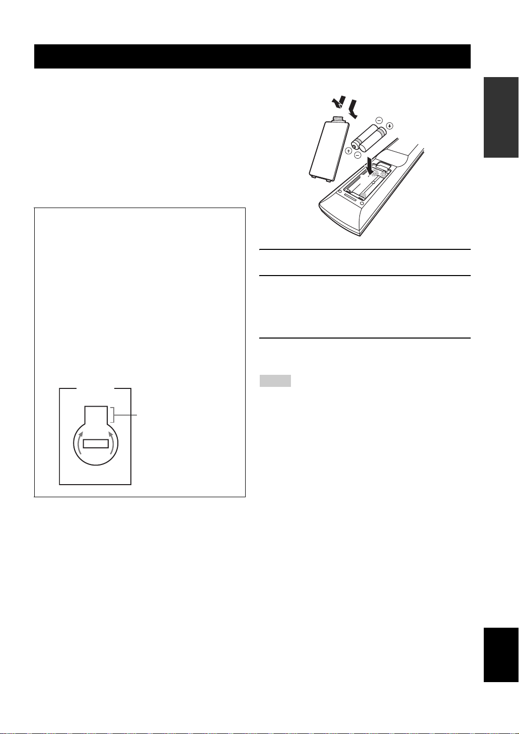
■ Installing batteries in the remote control
1
3
2
1 Take off the battery compartment cover.
2 Insert the two supplied batteries
(AAA, R03, UM-4) according to the polarity
markings (+ and –) on the inside of the
battery compartment.
3 Snap the battery compartment cover back
into place.
Notes
• Change all of the batteries if you notice that the operation range
of the remote control decreases.
• Do not use an old battery and a new one together.
• Do not use different types of batteries (such as alkaline and
manganese batteries) together. Read the packaging carefully as
these different types of batteries may have the same shape and
color.
• If the batteries have leaked, dispose of them immediately. Avoid
touching the leaked material or letting it come into contact with
clothing, etc. Clean the battery compartment thoroughly before
installing new batteries.
• Do not throw away batteries with general house waste; dispose
of them correctly in accordance with your local regulations.
• If the remote control is without batteries for more than 2
minutes, or if exhausted batteries remain in the remote control,
the contents of the memory may be cleared. When the memory
is cleared, insert new batteries and set up the remote control
code.
INTRODUCTION
3 En
English
Quick start guide
Quick start guide
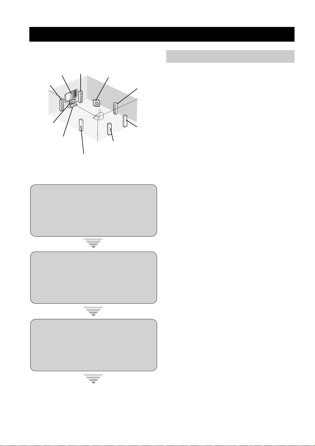
The following steps describe the easiest way to enjoy
DVD movie playback in your home theater.
Front right
Video monitor
Front left
speaker
Center speaker
DVD player
Step 1: Set up your speakers
Step 2: Connect your DVD player
speaker
Surround left
speaker
Subwoofer
Surround back left
speaker
Surround right
speaker
Surround back
right speaker
☞
P. 5
and other components
Preparation: Check the items
Prepare the following items.
❏ Speakers
❏ Front speaker .....................................x 2
❏ Center speaker ...................................x 1
❏ Surround speaker ..............................x 4
Select magnetically shielded speakers. The
minimum required speakers are two front speakers.
The priority of the requirement of other speakers is
as follows:
1. Two surround speakers
2. Center speaker
3. One (or two) surround back speaker(s)
❏ Active subwoofer ...................................x 1
Select an active subwoofer equipped with an RCA
input jack.
❏ Speaker cable .........................................x 7
❏ Subwoofer cable .....................................x 1
Select a monaural RCA cable.
❏ DVD player ..............................................x 1
Select DVD player equipped with coaxial digital
audio output jack and composite video output
jack.
❏ Video monitor..........................................x 1
Select a TV monitor, video monitor or projector
equipped with a composite video input jack.
❏ Video cable .............................................x 2
Select an RCA composite video cable.
Step 3: Press SCENE 1 button
Enjoy DVD playback!
4 En
☞
P. 6
☞
P. 7
❏ Digital coaxial audio cable ....................x 1
Step 1: Set up your speakers
Place your speakers in the room and connect them to this
unit.
SPEAKERS
COAXIAL
DVD
1
DTV/CBL
OUT
DVD
IN1 IN2
HDMI
REMOTE
IN
OUT
+12V
15mA MAX.
TRIGGER
OUT
L
R
MD/
IN
CD-R
(PLAY)
DVD
VIDEO
VIDEO
MONITOR
OUT
IN
DTV/CBL DVRDVD
IN
OUT
OUT
(REC)
DTV/CBL DVRDVD
4
OPTICAL
MD/CD-R
DTV/CBL MD/CD-R
DIGITAL
2
3
OUTPUT
DIGITAL INPUT
COMPONENT VIDEO ANTENNA
P
RPBYPRPB
MONITOR OUT
OUT S VIDEOIN
DTV/CBL DVRDVD
OUT
L
CENTER
R
SUB
FRONT(6CH)
SURROUND
WOOFER
SB(8CH)
CD
MULTI CH INPUTAUDIO
DOCK
DTV/CBL
Y
DVR
MONITOR
OUT
SUB
SUB
WOOFER
WOOFER
ZONE 2
OUTPUT
OUTPUT
OUT
1 Place your speakers and subwoofer in the
room.
SPEAKERS
AM
SURROUND BACK/BI-AMP
SURROUND BACK/BI-AMP
LR
SURROUND
LR
GND
FM
75
UNBAL.
SURROUND
LR
LR
SINGLE
SINGLE
LR
LR
FRONT B
FRONT ACENTER
FRONT B
FRONT ACENTER
AC OUTLETS
SWITCHED
LR
LR
Quick start guide
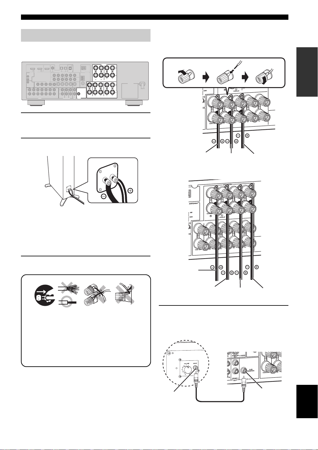
Be sure to connect the left channel (L), right channel
(R), “+” (red) and “–” (black) properly.
Front and center speakers
Loosen Insert Tighten
INTRODUCTION
2 Connect speaker cables to each speaker.
Cables are colored or shaped differently, perhaps with
a stripe, groove or ridge. Connect the striped
(grooved, etc.) cable to the “+” (red) terminals of
your speaker. Connect the plain cable to the “–”
(black) terminals.
3 Connect each speaker cable to the
corresponding speaker terminal of this unit.
12 3 4
1 Make sure that this unit and the subwoofer are
unplugged from the AC wall outlets.
2 Twist the exposed wires of the speaker cables
together to prevent short circuits.
3 Do not let the bare speaker wires touch each other.
4 Do not let the bare speaker wires touch any metal
part of this unit.
To the center
speaker
To the front
right speaker
To the front
left speaker
Surround and surround back speakers
To the surround
back right
speaker
To the surround
back left speaker
To the surround
right speaker
To the surround
left speaker
4 Connect the subwoofer cable to the input
jack of the subwoofer and the SUBWOOFER
OUTPUT jack of this unit.
Subwoofer
AV r eceive r
Input jack
Subwoofer cable
SUBWOOFER
OUTPUT jack
English
5 En
Quick start guide
Step 2: Connect your DVD player
and other components
COAXIAL
COAXIAL
DVD
1
1
DTV/CBL
OUT
DVD
IN1 IN2
HDMI
REMOTE
IN
OUT
+12V
15mA MAX.
TRIGGER
OUT
L
R
MD/
IN
CD-R
(PLAY)
DVD
VIDEO
VIDEO
VIDEO
VIDEO
MONITOR
MONITOR
OUT
IN
OUTIN
DTV/CBL DVRDVD
DTV/CBL DVRDVD
IN
OUT
OUT
(REC)
DTV/CBL DVRDVD
4
OPTICAL
OPTICAL
MD/CD-R
DTV/CBL CD
DTV/CBL CDDVD
DIGITAL
2
3
2
3
OUTPUT
DIGITAL INPUT
DIGITAL INPUT
COMPONENT VIDEO ANTENNA
P
RPBYPRPB
MONITOR OUT
OUT S VIDEOIN
OUT S VIDEOIN
DTV/CBL DVRDVD
DTV/CBL DVRDVD
OUT
OUT
L
CENTER
R
SUB
FRONT(6CH)
SURROUND
WOOFER
SB(8CH)
CD
MULTI CH INPUTAUDIO
DOCK
DTV/CBL
Y
DVR
MONITOR
MONITOR
OUT
OUT
SUB
WOOFER
ZONE 2
OUTPUT
OUT
Make sure that this unit and the DVD
player are unplugged from the AC wall
outlets.
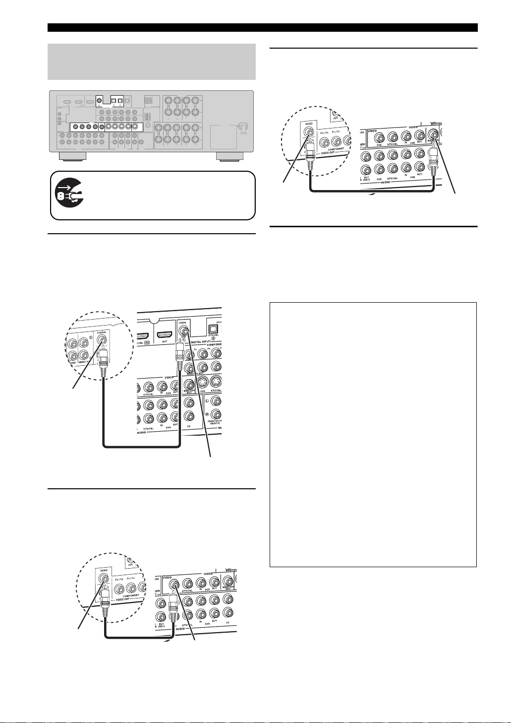
1 Connect the digital coaxial audio cable to the
digital coaxial audio output jack of your DVD
player and the DVD DIGITAL INPUT COAXIAL
jack of this unit.
DVD player
Digital coaxial
audio output jack
Digital coaxial audio
cable
2 Connect the video cable to the composite
video output jack of your DVD player and the
DVD VIDEO jack of this unit.
DVD player
SPEAKERS
AM
SURROUND BACK/BI-AMP
LR
GND
FM
75
UNBAL.
SURROUND
LR
SINGLE
LR
FRONT B
FRONT ACENTER
AC OUTLETS
SWITCHED
LR
AV r eceive r
DVD DIGITAL INPUT
COAXIAL jack
AV receiver
3 Connect the video cable to the video input
jack of your video monitor and the VIDEO
MONITOR OUT jack of this unit.
AV receiver
VIDEO MONITOR OUT
jack
Video input
jack
Video monitor
Video cable
4 Connect the power plug of this unit and other
components into the AC wall outlet.
y
This unit is equipped with AC OUTLET(S) for the power supply
of the other components (except Korea model). See page 22 for
details.
■ For further connections
• Using the other kind of speaker
combinations ☞ P. 11
• Connecting video components ☞ P. 16
• Connecting a DVD player ☞ P. 17
• Connecting a DVD recorder ☞ P. 18
• Connecting a set-top box ☞ P. 18
• Connecting a CD player
and a CD recorder/MD recorder ☞ P. 19
• Connecting a multi-format player
or an external decoder ☞ P. 19
• Connecting a Yamaha iPod/Bluetooth dock
☞ P. 20
• Connecting the REMOTE IN/OUT jacks
☞ P. 20
• Using the VIDEO AUX jacks on the front
panel ☞ P. 21
• Connecting an FM/AM antenna ☞ P. 21
• Using the USB jack on the front panel
☞ P. 51
Composite video
output jack
6 En
Video cable
DVD VIDEO jack
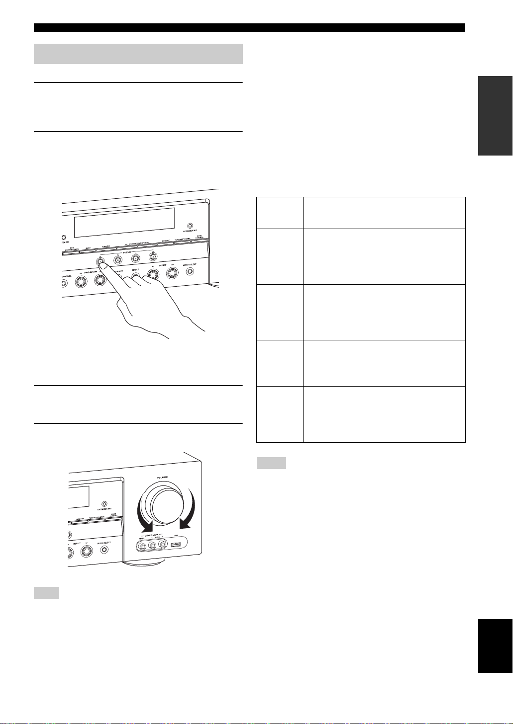
Step 3: Press SCENE 1 button
1 Turn on the video monitor and then set the
input source selector of the video monitor to
this unit.
2 Press
T
SCENE 1.
This unit is turned on. “DVD Viewing” appears in the
front panel display, and this unit automatically
optimize own status for the DVD playback.
Quick start guide
■ About SCENE function
Just by pressing one SCENE button, you can turn on this
unit and recall your favorite input source and sound field
program according to the SCENE template that has been
assigned to the SCENE button. The SCENE templates are
built combinations of input sources and sound field
programs.
y
If you connect a Yamaha product that has capability of the
SCENE control signals, this unit can automatically activate the
component and start playback. Refer to the instruction manual of
the DVD player for further information.
■ Using the other SCENE buttons
INTRODUCTION
y
The indicator on the selected SCENE button lights up while
this unit is in the SCENE mode.
3 Start playback of the desired DVD on your
player.
4 Rotate
Note
When you change the input source or sound field program, the
SCENE mode is deactivated, and the indicator on the selected
SCENE button turns off.
L
VOLUME to adjust the volume.
Default
SCENE
button
SCENE 1DVD Movie Viewing
SCENE 2Music Disc Listening
SCENE
3
SCENE
4
The name of the SCENE template
and its description
– input source: DVD
– sound field program: Movie Dramatic
For when you want to enjoy a movie from the
connected DVD player.
– input source: DVD
– sound field program: 2ch Stereo
For when you want to listen to a music disc
from the connected DVD player.
TV Viewing
– input source: DTV/CBL
– sound field program: STRAIGHT
For when you want to watch a TV program.
Radio Listening
– input source: TUNER
– sound field program: 7ch Enhancer
For when you want to listen to a music program
from the FM radio station.
*1
*2, *3, *4
Notes
*1
You must connect a cable TV or a satellite tuner to this unit in
advance. See page 16 for details.
*2
You need to connect the supplied FM and AM antennas to this
unit in advance. See page 21 for details.
*3
You must tune into the desired radio station. See pages 45 to 47
for the tuning information.
*4
To achieve the best possible reception, orient the connected
AM loop antenna, or adjust the position of the end of the
indoor FM antenna.
y
If you cannot find the desired situation, you can select and change
the assigned SCENE template for the SCENE buttons. See
page 30 for details.
English
7 En
Quick start guide
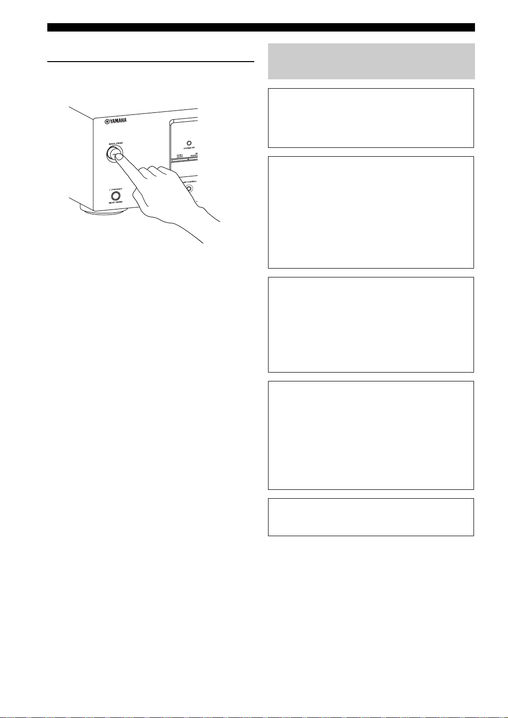
■ After using this unit...
Press AMAIN ZONE ON/OFF on the front
panel to set this unit to the standby mode.
This unit is set to the standby mode. In the standby mode,
this unit consumes a small amount of power in order to
receive infrared signals from the remote control. To turn
on this unit from the standby mode, press AMAIN ZONE
ON/OFF (or GPOWER). See page 23 for details.
What do you want to do with this unit?
■ Customizing the SCENE templates
• Using various SCENE templates ☞ P. 30
• Creating your original SCENE templates
☞ P. 33
■ Using various input sources
• Basic controls of this unit ☞ P. 35
• Enjoying FM/AM radio programs ☞ P. 45
• Using your USB portable device
with this unit ☞ P. 51
• Using your iPod with this unit ☞ P. 53
• Using your Bluetooth components
with this unit ☞ P. 55
■ Using various sound features
• Using various sound field programs
☞ P. 40
• Using the direct mode for the high
quality sound ☞ P. 43
• Customizing the sound field programs
☞ P. 42
■ Adjusting the parameters of this unit
• Automatically optimizing the speaker
parameters for your listening room (AUTO
SETUP) ☞ P. 26
• Manually adjusting various parameters of
this unit ☞ P. 57
• Setting the remote control ☞ P. 71
• Adjusting the advanced parameters☞ P. 77
■ Additional features
Automatically turning off this unit ☞ P. 39
8 En
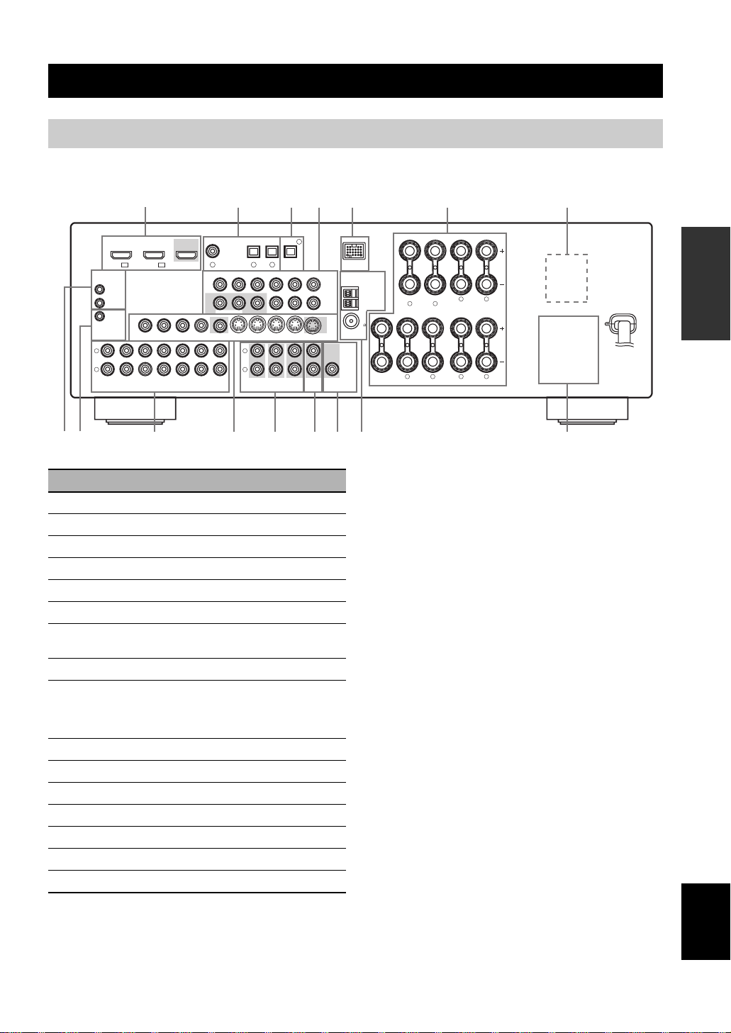
Rear panel
EA D FCB08 9
Connections
Connections
L
R
(PLAY)
REMOTE
IN
OUT
+12V
15mA MAX.
TRIGGER
IN
DVD
IN1 IN2
HDMI
VIDEO
OUT
MD/
OUT
CD-R
(REC)
1
DTV/CBL
OUT
VIDEO
IN
DTV/CBL DVRDVD
IN
DTV/CBL DVRDVD
2 4 53 6 7
COAXIAL
DVD
1
DVD
MONITOR
OUT
OUT
OPTICAL
DTV/CBL
MD/CD-R4MD/CD-R
DIGITAL
2
3
DIGITAL INPUT
RPB
P
MONITOR OUT
OUT
CD
OUTPUT
COMPONENT VIDEO ANTENNA
YPRPBY
MONITOR
OUT S VIDEOIN
DTV/CBL DVRDVD
L
R
FRONT(6CH)
SB(8CH)
SURROUND
MULTI CH INPUTAUDIO
CENTER
SUB
WOOFER
ZONE 2
OUT
OUT
Name Page
1 HDMI jacks 14
2 DIGITAL INPUT jacks 13
3 DIGITAL OUTPUT jack 13
4 COMPONENT VIDEO jacks 13
5 DOCK terminal 20
6 Speaker terminals 11
7 VOLTAGE SELECTOR
(Asia and General models only)
8 REMOTE IN/OUT jacks 20
9
TRIGGER OUT jack
This is a control expansion jack for custom
installation.
0 AUDIO jacks 13
A VIDEO jacks 13
B MULTI CH INPUT jacks 19
C ZONE 2 OUT jacks 74
D SUBWOOFER OUTPUT jack 11
E ANTENNA terminals 21
F AC OUTLET(S) 22
DTV/CBL
DVR
OUTPUT
WOOFER
SPEAKERS
DOCK
AM
SURROUND BACK/BI-AMP
GND
FM
75
UNBAL.
SUB
LR
SINGLE
LR
FRONT ACENTER
SURROUND
FRONT B
LR
AC OUTLETS
SWITCHED
LR
PREPARATION
3
—
English
9 En
Connections
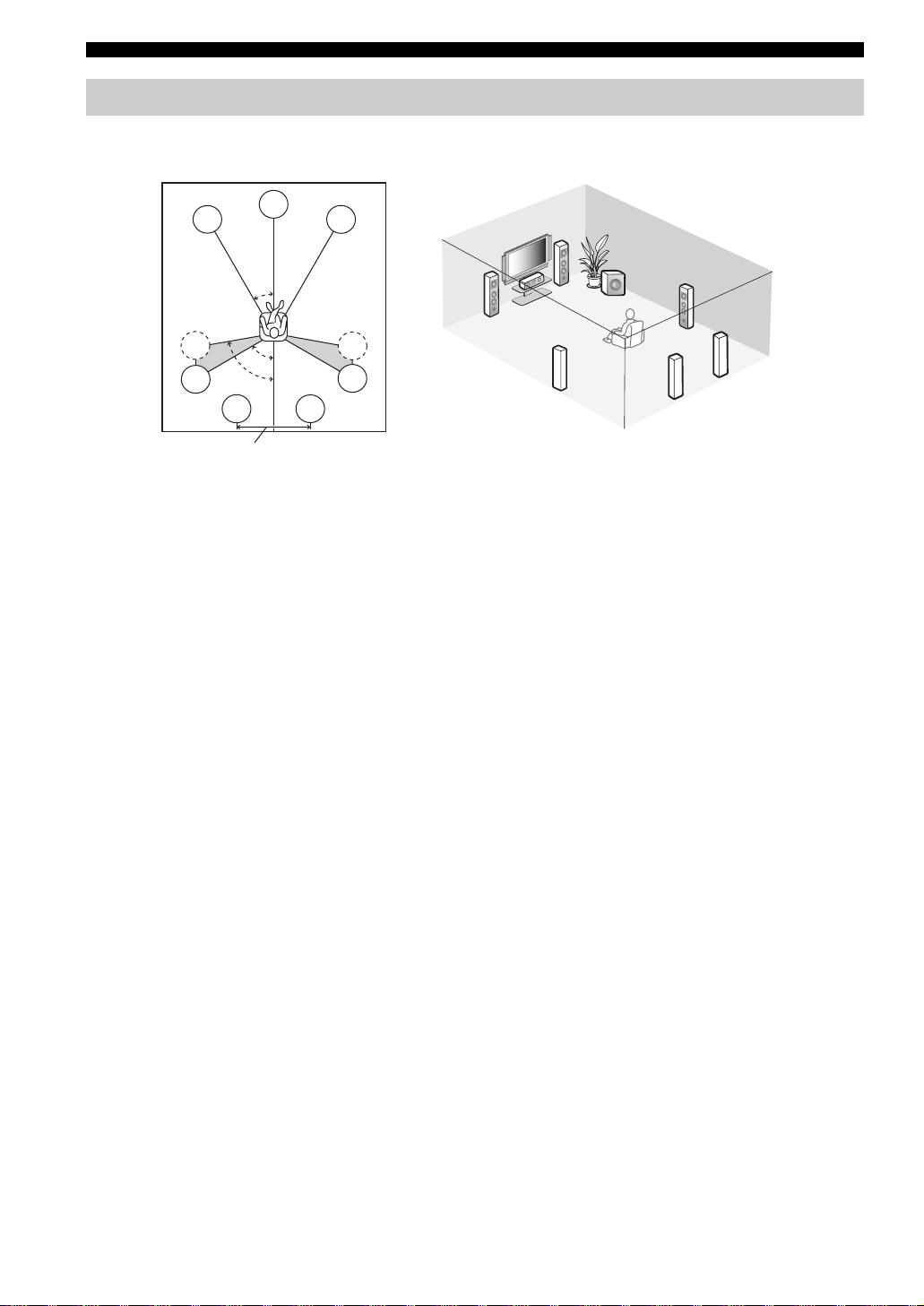
Placing speakers
The speaker layout below shows the speaker setting we recommend. You can use it to enjoy CINEMA DSP and
multi-channel audio sources.
FL
C
FR
FR
30˚
FL
SW
SR
C
SL
SL
30 cm (12 in) or more
80˚
SBL
60˚
SBR
SR
SR
SL
SBR
SBL
Front left and right speakers (FL and FR)
The front speakers are used for the main source sound plus effect sounds. Place these speakers at an equal distance from the
ideal listening position. The distance of each speaker from each side of the video monitor should be the same.
Center speaker (C)
The center speaker is for the center channel sounds (dialog, vocals, etc.). If for some reason it is not practical to use a
center speaker, you can do without it. Best results, however, are obtained with the full system.
Surround left and right speakers (SL and SR)
The surround speakers are used for effect and surround sounds.
Surround back left and right speakers (SBL and SBR)
The surround back speakers supplement the surround speakers and provide more realistic front-to-back transitions.
Subwoofer (SW)
The use of a subwoofer with a built-in amplifier, such as the Yamaha Active Servo Processing Subwoofer System, is
effective not only for reinforcing bass frequencies from any or all channels, but also for high fidelity sound reproduction
of the LFE (low-frequency effect) channel included in Dolby Digital and DTS sources. The position of the subwoofer is
not so critical, because low bass sounds are not highly directional. But it is better to place the subwoofer near the front
speakers. Turn it slightly toward the center of the room to reduce wall reflections.
10 En
Connections
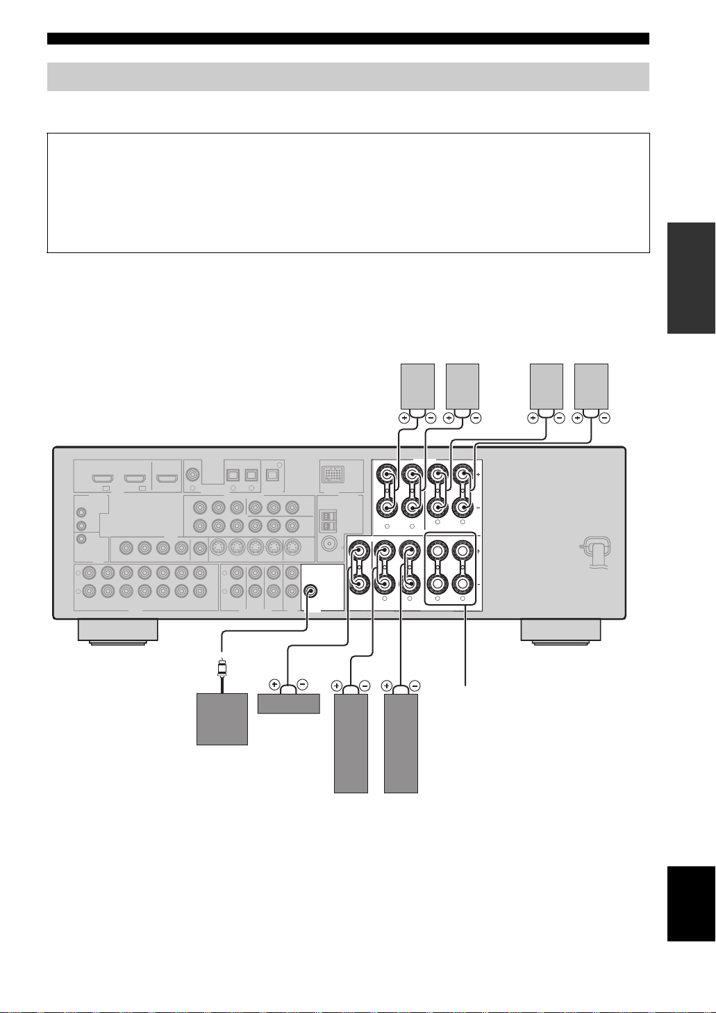
Connecting speakers
Be sure to connect the left channel (L), right channel (R), “+” (red) and “–” (black) properly. If the connections are faulty,
this unit cannot reproduce the input sources accurately.
Caution
• Before connecting the speakers, make sure that the AC power plug is disconnected from the AC wall outlet.
• Do not let the bare speaker wires touch each other or let them touch any metal part of this unit. This could damage
this unit and/or the speakers. If the speaker wires are short-circuited, “CHECK SP WIRES” appears in the front
panel display when you turn on this unit.
• Use the magnetically shielded speakers. If this type of speaker still creates interference with the monitor, place the
speakers away from the monitor.
When you use single surround
back speaker, connect the
speaker to the left SURROUND
BACK terminal (SINGLE).
Surround back speakers
Right
Left
Surround speakers
Right
Left
PREPARATION
L
R
(PLAY)
OUT
+12V
15mA MAX.
IN
DVD
IN1 IN2
REMOTE
IN
TRIGGER
OUT
MD/
CD-R
(REC)
SURROUND BACK/BI-AMP
SINGLE
LR
FRONT ACENTER
SPEAKERS
LR
SURROUND
FRONT B
LR
AC OUTLETS
SWITCHED
LR
COAXIAL
DTV/CBL MD/CD-R
DTV/CBL
HDMI
VIDEO
DTV/CBL DVRDVD
OUT
DTV/CBL DVRDVD
DVD
OUT
DVD
VIDEO
IN
OUT
OUT
IN
2
1
DIGITAL INPUT
COMPONENT VIDEO ANTENNA
RPB
P
MONITOR OUT
MONITOR
DTV/CBL DVRDVD
OUT
L
R
FRONT(6CH)
SB(8CH)
CD
4
OPTICAL
MD/CD-R
DIGITAL
3
OUTPUT
YPRPBY
OUT S VIDEOIN
CENTER
SUB
WOOFER
SURROUND
MULTI CH INPUTAUDIO
MONITOR
OUT
ZONE 2
OUT
DTV/CBL
DVR
OUTPUT
SUB
WOOFER
DOCK
AM
GND
FM
75
UNBAL.
FRONT B terminals
Connect the alternative front speaker system
Center
(FRONT B).
speaker
Subwoofer
Right
Left
Front speakers
(FRONT A)
11 En
English
Connections
■ Before connecting to the SPEAKERS
terminal
A speaker cord is actually a pair of insulated cables
running side by side. Cables are colored or shaped
differently, perhaps with a stripe, groove or ridges.
Connect the striped (grooved, etc.) cable to the “+” (red)
terminals of this unit and your speaker. Connect the plain
cable to the “–” (black) terminals.
Remove approximately 10 mm (3/8”) of insulation
from the end of each speaker cable and then
twist the bare wires of the cable together to
prevent short circuits.
10 mm (3/8”)
■ Connecting to the FRONT A terminals
2
1
Red: positive (+)
Black: negative (–)
3
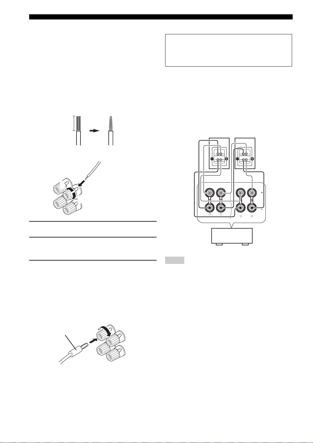
■ Using bi-amplification connections
Caution
Remove the shorting bars or bridges to separate the
LPF (low pass filter) and HPF (high pass filter)
crossovers.
This unit allows you to make bi-amplification connections
to one speaker system. Check if your speakers support
bi-amplification.
To make the bi-amplification connections, use the FRONT
and SURROUND BACK terminals as shown below. To
activate the bi-amplification connections, set “BI-AMP”
to “ON” in “Advanced setup” (see page 77).
Front speakers
Right
Left
1 Loosen the knob.
2 Insert the bare end of the speaker wire into
the hole on the terminal.
3 Tighten the knob to secure the wire.
Connecting the banana plug
(except Europe, Russia, Korea, and Asia models)
The banana plug is a single-pole electrical connector
widely used to terminate speaker cables. First, tighten the
knob and then insert the banana plug connector into the
end of the corresponding terminal.
Banana plug
FRONT A
This unit
SINGLE
LR
SURROUND BACK/BI-AMP
LR
Notes
• When you make the conventional connection, make sure that
the shorting bars are put into the terminals appropriately. Refer
to the instruction manuals of the speakers for details.
• When you use bi-amplification connections, you can not use
surround back speakers.
12 En
Connections
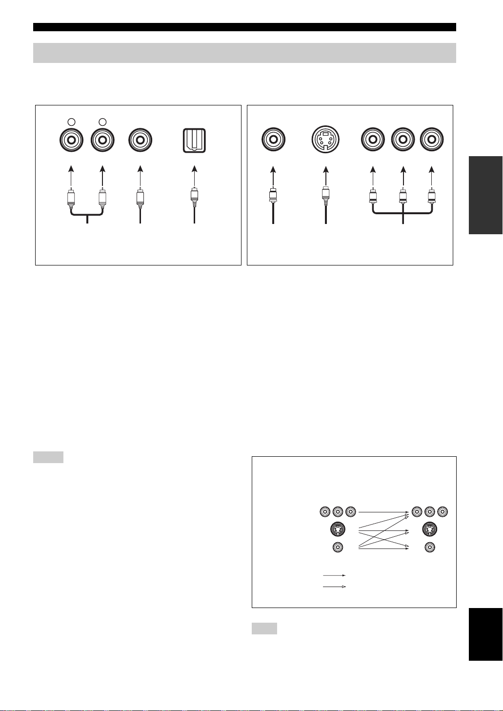
Information on jacks and cable plugs
Connect one of the type of the audio jack(s) and/or video jack(s) that your input components are equipped with.
Audio jacks and cable plugs Video jacks and cable plugs
AUDIO
L
L
Left and right
analog audio
cable plugs
R
(Red)(White) (Orange) (Yellow) (Red) (Blue) (Green)
R
DIGITAL AUDIO
COAXIAL
C
Coaxial
digital audio
cable plug
DIGITAL AUDIO
OPTICAL
O
Optical
digital
audio cable
plug
■ Audio jacks
This unit has three types of audio jacks. Connection
depends on the availability of audio jacks on your other
components.
AUDIO jacks
For conventional analog audio signals transmitted via left
and right analog audio cables. Connect red plugs to the
right jacks and white plugs to the left jacks.
DIGITAL AUDIO COAXIAL jack
For digital audio signals transmitted via a coaxial digital
audio cable.
DIGITAL AUDIO OPTICAL jacks
For digital audio signals transmitted via optical digital
audio cables.
Notes
• You can use the digital jacks to input PCM, Dolby Digital and
DTS bitstreams. Optical input jacks are compatible with digital
signals with up to 96 kHz of sampling frequency.
• This unit handles digital and analog signals independently. Thus
audio signals input at the digital jacks are not output at the
analog AUDIO OUT (REC) jacks.
VIDEO S VIDEO
V
Composite
video cable
plug
S
S-video
cable plug
COMPONENT VIDEO
P
R
P
B
PR
PB
Component
video cable
plugs
Y
Y
■ Video jacks
This unit has three types of video jacks. Connection
depends on the availability of input jacks on your video
monitor.
VIDEO jacks
For conventional composite video signals transmitted via
composite video cables.
S VIDEO jacks
For S-video signals, separated into the luminance (Y) and
chrominance (C) video signals transmitted on separate
wires of S-video cables.
COMPONENT VIDEO jacks
For component signals, separated into the luminance (Y)
and chrominance (P
separate wires of component video cables.
Video signal flow for MONITOR OUT
COMPONENT
VIDEO
S VIDEO
B, PR) video signals transmitted on
Input
PR PB Y PR PB Y
Output
(MONITOR OUT)
PREPARATION
VIDEO
Through
Video conversion ON
(see page 67)
Note
The OSD signal is not output at the DVR OUT (REC) jacks.
13 En
English
Connections
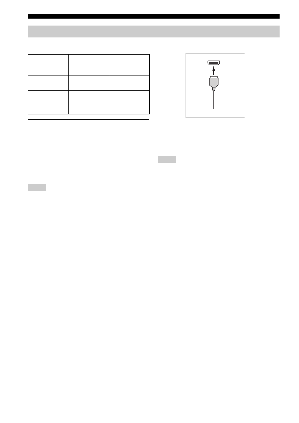
Information on HDMI™
■ HDMI compatibility with this unit
Audio signal
types
2ch Linear PCM 2ch, 32-192 kHz,
Multi-ch Linear
PCM
Bitstream Dolby Digital, DTS DVD-Video, etc.
Audio signal
formats
16/20/24 bit
8ch, 32-192 kHz,
16/20/24 bit
This unit’s HDMI interface is based on the following
standards:
• HDMI Version 1.2a (High-Definition Multimedia
Interface Specification Version 1.2a) licensed by
HDMI Licensing, LLC.
• HDCP (High-bandwidth Digital Content Protection
System) licensed by Digital Content Protection,
LLC.
Notes
• When CPPM copy-protected DVD audio is played back, video
and audio signals may not be output depending on the type of
the DVD player.
• This unit is not compatible with HDCP-incompatible HDMI or
DVI components.
• You can check the potential problem about the HDMI
connection (see page 38).
Compatible
HDMI
components
CD, DVD-Video,
DVD-Audio, etc.
DVD-Audio, etc.
■ HDMI jack and cable plug
HDMI
HDMI cable plug
y
• We recommend using an HDMI cable shorter than 5 meters (16
feet) with the HDMI logo printed on it.
• Use a conversion cable (HDMI jack
this unit to other DVI components.
Notes
• Do not disconnect or connect the cable or turn off the power of
the HDMI components connected to the HDMI OUT jack of
this unit while data is being transferred. Doing so may disrupt
playback or cause noise.
• Audio signals input at input jacks other than the HDMI IN DVD
or HDMI IN DTV/CBL jack of this unit cannot be digitally
output at the HDMI OUT jack.
• If you turn off the power of the video monitor connected to the
HDMI OUT jack via a DVI connection, this unit may fail to
establish the connection to the component.
↔ DVI-D jack) to connect
14 En
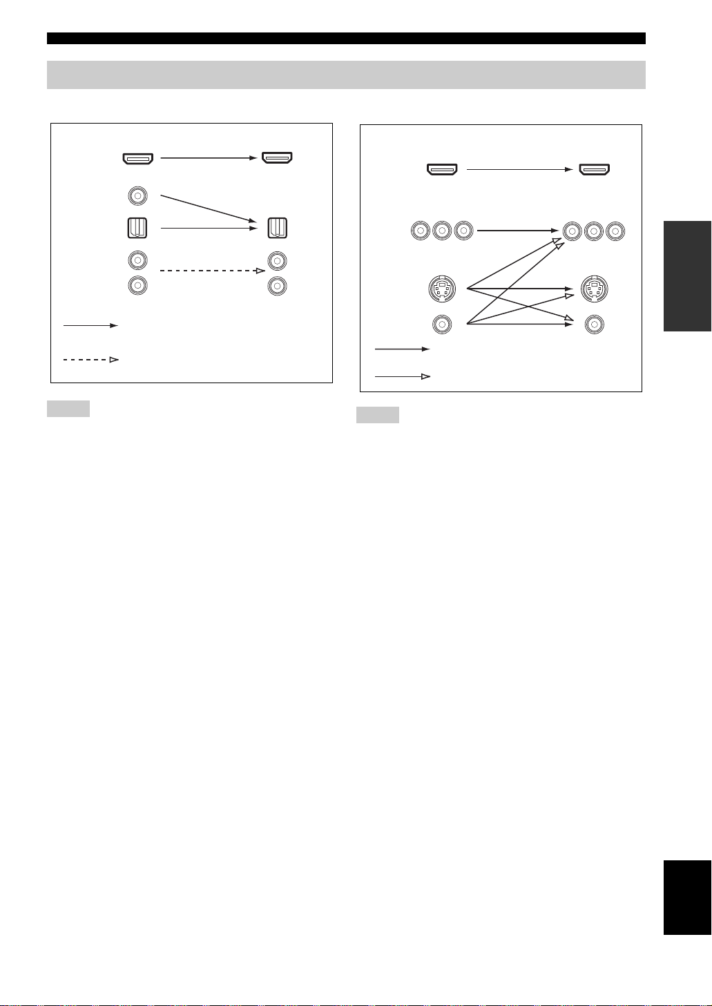
Audio and video signal flow
Connections
■ Audio signal flow
OutputInput
HDMI
DIGITAL AUDIO
(COAXIAL)
DIGITAL AUDIO
(OPTICAL)
AUDI O
Digital output
Analog output
Notes
• 2-channel as well as multi-channel PCM, Dolby Digital and
DTS signals input at the HDMI IN DVD or HDMI IN
DTV/CBL jack can be output at the HDMI OUT jack only
when “SUPPORT AUDIO” is set to “Other” (see page 64).
• Audio signals input at the HDMI IN jacks are not output at the
AUDIO output and DIGITAL OUTPUT jacks.
■ Video signal flow
OutputInput
HDMI
COMPONENT
VIDEO
S VIDEO
VIDEO
Through
Video conversion ON (see page 67)
Notes
• When the all video signals are input at the HDMI,
COMPONENT VIDEO, S VIDEO and VIDEO jacks, the
priority order of the input signals is as follows:
1. HDMI
2. COMPONENT VIDEO
3. S VIDEO
4. VIDEO
• When some digital video signals are input at the HDMI IN
DVD or HDMI IN DTV/CBL jack, the video conversion
function does not work.
• Digital video signals input at the HDMI IN DVD or HDMI IN
DTV/CBL jack cannot be output from analog video output
jacks.
PREPARATION
15 En
English
Connections
O
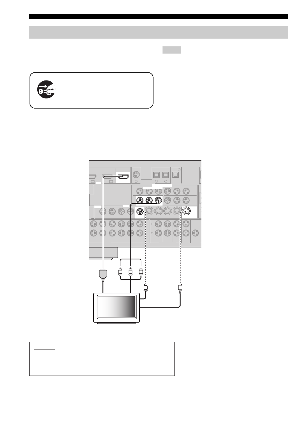
Connecting video components
Connect your TV (or projector) to the HDMI OUT jack,
the COMPONENT VIDEO MONITOR OUT jacks, the S
VIDEO MONITOR OUT jack or the VIDEO MONITOR
OUT jack of this unit.
Make sure that this unit and other
components are unplugged from the
AC wall outlets.
y
You can choose to play back HDMI audio signals on this unit or
on another HDMI component connected to the HDMI OUT jack
of this unit. Use the “SUPPORT AUDIO” parameter in “SOUND
MENU” to select the component to play back HDMI audio
signals (see page 64).
COAXIAL
DVD
1
DTV/CBL
D
IN1 IN2
HDMI
HDMI
TE
VIDEO
VIDEO
AX.
ER
T
/ -ROUT
(REC)
OUT
OUT
IN
DTV/CBL DVRDVD
DTV/CBL DVRDVD
VIDEO
VIDEO
DIGITAL INPUT
DVD
RPB
P
RPB
P
MONITOR OUT
MONITOR OUT
MONITOR
MONITOR
OUT
OUT
OUT
OUTIN
CD
Notes
• Some video monitors connected to this unit via a DVI
connection fail to recognize the HDMI audio/video signals
being input if they are in the standby mode. In this case, the
HDMI indicator flashes irregularly.
• When you connect your TV monitor or projector via HDMI
connection, the OSD does not appear. In such cases, connect the
TV monitor or projector via component, S-video or video
connection.
• Connect the input source components to the HDMI IN DVD or
HDMI IN DTV/CBL jack to display the video images on the
video monitor connected to the HDMI OUT jack.
OPTICAL
DTV/CBL MD/CD-R
2
COMPONENT VIDEO
COMPONENT VIDEO
DTV/CBL DVRDVD
L
R
FRONT(6CH)
SB(8CH)
MULTI CH INPUTAUDIO
4
MD/CD-R
DIGITAL
3
OUTPUT
Y
YPRPBY
MONITOR
MONITOR
OUT S VIDEOIN
OUT
OUT
CENTER
SUB
SURROUND
WOOFER
ZONE 2
OUT
DTV/CBL
DVR
S VIDEO
W
OUTPUT
16 En
PR PB
HDMI in
Component
video in
TV (or projector)
indicates recommended connections
indicates alternative connections
(One for the video connection,
and one for the audio connection)
Y
V
Video in
S-video in
S
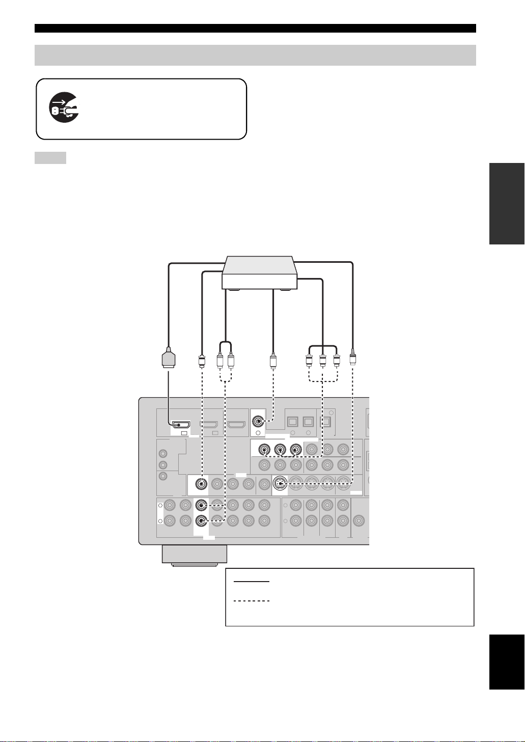
Connecting other components
O
Make sure that this unit and other
components are unplugged from the
AC wall outlets.
Notes
• When “VIDEO CONV.” is set to “OFF” (see page 67), be sure
to make the same type of video connections as those made for
your TV (see page 16). For example, if you connected your TV
to the VIDEO MONITOR OUT jack of this unit, connect your
other components to the VIDEO jacks.
■ Connecting a DVD player
DVD player
HDMI out
Connections
• When “VIDEO CONV.” is set to “ON” (see page 67), the
converted video signals are output only at the MONITOR OUT
jacks. To record a source, make the same type of video
connections between each component.
• To make a digital connection to a component other than the
default component assigned to DIGITAL INPUT jack, select
the corresponding setting for “OPTICAL IN” or “COAXIAL
IN” in “I/O ASSIGNMENT” (see page 65).
• If you connect your DVD player to both the DIGITAL INPUT
(OPTICAL) and the DIGITAL INPUT (COAXIAL) jacks,
priority is given to the signals input at the DIGITAL INPUT
(COAXIAL) jack.
S-video out
PREPARATION
Video out
V
DTV/CBL
DVD
IN1 IN2
DVD
IN1
HDMI
HDMI DIGITAL INPUT
REMOTE
IN
OUT
+12V
VIDEO
VIDEO
15mA MAX.
TRIGGER
OUT
L
L
R
R
MD/
IN
CD-R
(PLAY)
DTV/CBL DVRDVD
DVD DVD
OUT
(REC)
DTV/CBL DVRDVD
DVD
AUDIO
Component
video out
VIDEO
VIDEO
Coaxial out
OUT S VIDEOIN
CENTER
SUB
WOOFER
S
4
DTV/CBL
DVR
MONITOR
S VIDEO
OUT
W
ZONE 2
OUTPUT
OUT
C
COAXIAL
COAXIAL
DVD
DVD
1
1
DIGITAL INPUT
DVD
DVD
RPB
P
RPB
P
MONITOR OUT
MONITOR
OUT
OUT
OUT
CD
PR PB Y
OPTICAL
DTV/CBL MD/CD-R
2
3
COMPONENT VIDEO
COMPONENT VIDEO
YPRPBY
Y
DTV/CBL DVRDVD
L
R
FRONT(6CH)
SURROUND
SB(8CH)
MULTI CH INPUTAUDIO
MD/CD-R
DIGITAL
OUTPUT
Audio out
LR
OUT
IN
IN
indicates recommended connections
indicates alternative connections
(One for the video connection,
and one for the audio connection)
English
17 En
Connections
O
DTV/CBL MD/CD-R
DVD
MD/CD R
O
■ Connecting a DVD recorder, PVR or VCR
1
OUT
IN
IN
IN
VIDEO
VIDEO
DVR
DVR
DIGITAL INPUT
COMPONENT VIDEO
MONITOR OUT
MONITOR
OUT
CD
RPB
P
COMPONENT VIDEO
DTV/CBL DVRDVD
L
R
FRONT(6CH)
SB(8CH)
DVD
OUT
OUTIN
OUT
OUT
V
Audio in
L
Video in
R
L
L
L
R
R
(PLAY)
IN
REMOTE
IN
OUT
+12V
15mA MAX.
TRIGGER
DVD
IN1 IN2
HDMI
VIDEO
VIDEO
OUT
MD/
OUT
CD-R
(REC)
V
DTV/CBL
AUDIO
DTV/CBL DVRDVD
DTV/CBL DVRDVD
Audio out
R
DIGITAL
2
3
OUTPUT
YPRPBY
RPB
P
DVR
CENTER
SURROUND
WOOFER
MULTI CH INPUTAUDIO
S-video out
S
DTV/CBL
Y
DVR
DVR
MONITOR
OUT S VIDEOIN
OUT S VIDEOIN
OUT
ZONE 2
OUT
S
W
OUTPUT
S-video in
PR PB Y
SUB
Component video out
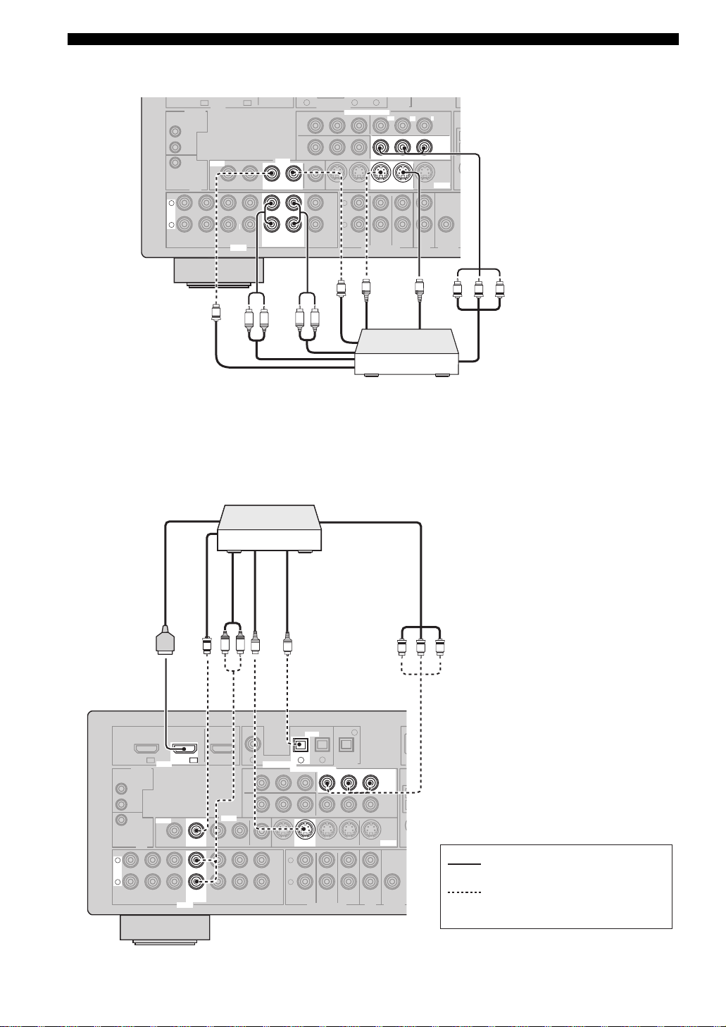
■ Connecting a set-top box
Satellite receiver, cable TV
receiver or HDTV decoder
HDMI out Component video out
Video out
Audio out
L R
V
COAXIAL
OUT
VIDEO
VIDEO
IN
IN
DVD
DVD
OUT
OUT
L
L
R
R
DTV/CBL
DTV/CBL
(PLAY)
REMOTE
IN
OUT
+12V
15mA MAX.
TRIGGER
IN
DVD
IN1 IN2
OUT
MD/
CD-R
(REC)
IN2
HDMI DIGITAL INPUT
HDMI
VIDEO
VIDEO
DTV/CBL DTV/CBL
DTV/CBL DVRDVD
OUT
DTV/CBL
DTV/CBL DVRDVD
AUDIO
S-video out
S
1
MONITOR OUT
MONITOR
OUT
CD
DIGITAL INPUT
RPB
P
Video out
Optical out
O
OPTICAL
OPTICAL
DTV/CBL MD/CD-R
DTV/CBL
2
2
COMPONENT VIDEO
COMPONENT VIDEO
YPRPBY
DTV/CBL DVRDVD
L
R
FRONT(6CH)
SB(8CH)
MULTI CH INPUTAUDIO
3
SURROUND
MD/CD-R
DIGITAL
OUTPUT
RPB
P
OUT S VIDEOIN
CENTER
SUB
WOOFER
DVD recorder,
PVR or VCR
4
DTV/CBL
DTV/CBL
Y
DVR
MONITOR
S VIDEO
OUT
ZONE 2
OUTPUT
OUT
PR PB Y
W
indicates recommended
connections
indicates alternative connections
(One for the video connection,
and one for the audio connection)
18 En
Connecting audio components
Connections
Connect the audio components as follows.
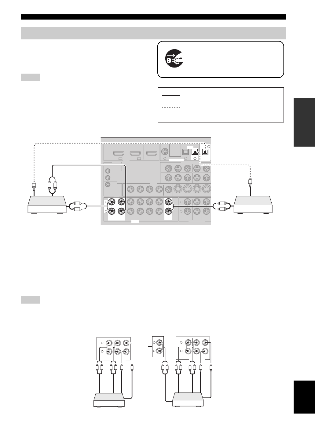
■ Connecting a CD player and a CD
recorder/MD recorder
Notes
• When you connect your CD player via analog and digital
connection, priority is given to the signal input at the DIGITAL
INPUT jack.
• To make a digital connection to a component other than the
default component assigned to each DIGITAL INPUT jack,
select the corresponding setting in “I/O ASSIGNMENT” (see
page 65).
DTV/CBL
IN1 IN2
HDMI
REMOTE
Optical in
O
L
MD recorder
R
Audio in
L
R
Audio out
IN
OUT
+12V
VIDEO
15mA MAX.
TRIGGER
OUT
L
L
R
R
MD/
IN
MD/
IN
CD-R
(PLAY)
CD-R
(PLAY)
DTV/CBL DVRDVD
OUT
OUT
(REC)
(REC)
DTV/CBL DVRDVD
AUDIO
Make sure that this unit and other
components are unplugged from the
AC wall outlets.
indicates recommended connections
PREPARATION
indicates alternative connections
COAXIAL
DVD
1
OUTDVD
IN
IN
VIDEO
DIGITAL INPUT
DIGITAL INPUT
DVD
MONITOR OUT
MONITOR
OUT
OUT
OUT
CD
CD
RPB
P
OPTICAL
OPTICAL
DTV/CBL CD
2
COMPONENT VIDEO
DTV/CBL DVRDVD
L
R
FRONT(6CH)
SB(8CH)
MULTI CH INPUTAUDIO
CD
MD/CD-R
MD/CD-R
DIGITAL
DIGITAL
3
3
OUTPUT
OUTPUT
YPRP
OUTIN
CENTER
SUB
SURROUND
WOOFER
4
4
Audio out
O
Optical out
L
R
CD playerCD recorder or
■ Connecting a multi-format player or an external decoder
This unit is equipped with 6 additional input jacks (left and right FRONT, CENTER, left and right SURROUND and
SUBWOOFER) for discrete multi-channel input from a multi-format player, external decoder, sound processor or
pre-amplifier.
If you set “INPUT CH” to “8ch” in “MULTI CH SET” (see page 67), you can use the input jacks assigned as “FRONT”
in “MULTI CH SET” (see page 67) together with the MULTI CH INPUT jacks to input 8-channel signals.
Connect the output jacks on your multi-format player or external decoder to the MULTI CH INPUT jacks. Be sure to
match the left and right outputs to the left and right input jacks for the front and surround channels.
Notes
• When you select the component connected to the MULTI CH INPUT jacks as the input source (see page 36), this unit automatically
turns off the digital sound field processor, and you cannot select sound field programs.
• This unit does not redirect signals input at the MULTI CH INPUT jacks to accommodate for missing speakers. We recommend that
you connect at least a 5.1-channel speaker system before using this feature.
SB(8CH)
MULTI CH INPUT
Surround out
SURROUND
CENTER
SUB
WOOFER
Subwoofer out
Center out
Multi-format player/External
decoder (7.1-channel output)
L
R
L R LR
Front out
FRONT(6CH)
SB(8CH)
Surround out
SURROUND
MULTI CH INPUT
CENTER
WOOFER
L
*1
SUB
R
Subwoofer out
Center out
Front out
Surround back out
L
R
FRONT(6CH)
L R LRL R
Multi-format player/External
decoder (5.1-channel output)
*1
The analog audio input jacks assigned as “FRONT” in “MULTI CH SET” (see page 67).
English
19 En
Connections
C
DVD
IN1
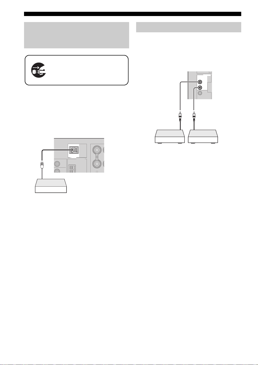
Connecting a Yamaha iPod™ universal dock or Bluetooth™ adapter
Make sure that this unit and other
components are unplugged from the
AC wall outlets.
This unit is equipped with the DOCK terminal on the rear
panel that allows you to connect a Yamaha iPod universal
dock (such as YDS-10, sold separately) or Bluetooth
adapter (such as YBA-10, sold separately). Connect a
Yamaha iPod universal dock or Bluetooth adapter to the
DOCK terminal on the rear panel of this unit using its
dedicated cable.
DOCK
DOCK
DTV/CBL
Y
Yamaha iPod universal dock
or Bluetooth adapter
ANTENNA
AM
DVR
GND
SURROUND BA
R
Using REMOTE IN/OUT jacks
When the components are the Yamaha products and have
the capability of the transmission of the remote control
signals, connect the REMOTE IN jack and REMOTE
OUT jack to the remote control input and output jack with
the monaural analog mini cable as follows.
REMOTE
REMOTE
IN
IN
OUT
OUT
+12V
15mA MAX.
Remote
control out
Infrared signal
receiver or
Yam ah a
component
y
• If the components have the capability of the SCENE control
signals, this unit can automatically activate the corresponding
components and start the playback when you use one of the
SCENE buttons. Refer to the owner’s manuals for details about
the capability of the SCENE control signals of the components.
• If the component connected to the REMOTE OUT jack is not
the Yamaha product, set “SCENE IR” in the advanced setup
menu to “OFF” (see page 77).
Remote
control in
Yamah a
component
(CD or DVD
player, etc.)
20 En
Connections
R
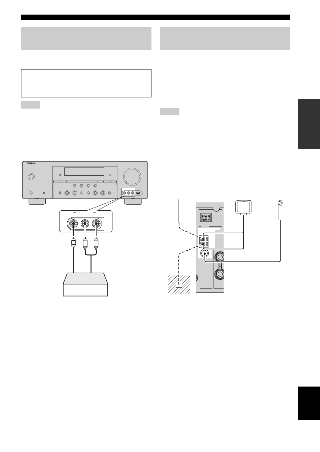
Using the VIDEO AUX jacks on the front panel
Use the VIDEO AUX jacks on the front panel to connect a
game console or a video camera to this unit.
Caution
Be sure to turn down the volume of this unit and other
components before making connections.
Notes
• To reproduce the source signals input at these jacks, select
“V-AUX” as the input source.
• When audio signals are input at the AUDIO jacks and the
DOCK terminal on the rear panel, the priority order of the input
signal is as follows:
1. DOCK
2. AUDIO
VOLUME
ZONE
CONTROL
VIDEO AUX USB
VIDEO L AUDIO R
SILENT CINEMA
MAIN ZONE
ON/OFF
PHONES
SYSTEM OFF
ZONE 2
EDIT
ON/OFF
PRESET/TUNING
SPEAKERS
TONE CONTROL
A/B/OFF
l
PRESET/TUNING/CH
BAND
A/B/C/D/E
SCENE
1234
DIRECTSTRAIGHT
EFFECT
VIDEO AUX
VIDEO L AUDIO R
OPTIMIZER MIC
h
MEMORY
TUNING AUTO/MAN'L
l INPUT hl PROGRAM h
AUDIO SELECT
Connecting the FM and AM antennas
Both FM and AM indoor antennas are supplied with this
unit. Connect each antenna correctly to the designated
terminals. In general, these antennas should provide
sufficient signal strength.
y
See page 22 for connection information of the supplied AM loop
antenna.
Notes
• The AM loop antenna should be placed away from this unit.
• The AM loop antenna should always be connected, even if an
outdoor AM antenna is connected to this unit.
• A properly installed outdoor antenna provides clearer reception
than an indoor one. If you experience poor reception quality,
install an outdoor antenna. Consult the nearest authorized
Yamaha dealer or service center about outdoor antennas.
Outdoor AM antenna
Use a 5 to 10 m (16 to 33
ft) vinyl-covered wire
extended outdoors from a
window.
AM loop
antenna
(supplied)
Indoor FM
antenna
(supplied)
PREPARATION
V
L
Vid eo
output
Game console or
video camera
R
Audio
output
DOCK
ANTENNA
ANTENNA
AM
AM
GND
GND
FM
FM
75
75
UNBAL.
UNBAL.
SUB
WOOFER
CENTE
UT
Ground (GND terminal)
For maximum safety and minimum interference, connect the
GND terminal to a good earth ground. A good earth
antenna
ground is a metal stake driven into moist earth.
English
21 En
Connections
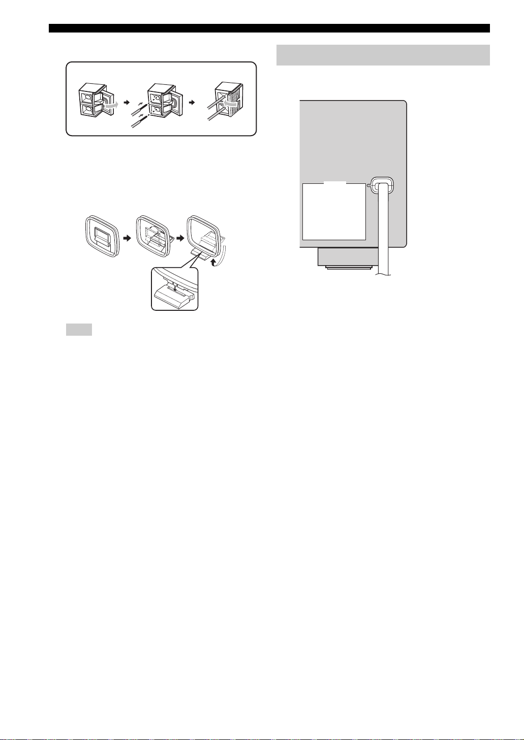
Connecting the wire of the AM loop antenna
Open the lever
Insert
Close the lever
y
The wire of the AM loop antenna does not have any polarity
and you can connect either end of the wire to AM or GND
terminal.
Assembling the supplied AM loop antenna
Note
The types of the supplied AM loop antenna is different
depending on the models.
Connecting the power cable
Once all connections are complete, plug the power cable
into the AC wall outlet.
AC OUTLETS
AC OUTLETS
SWITCHED
SWITCHED
Power cable
■ AC OUTLET(S) (SWITCHED)
Australia model...................................................... 1 outlet
Korea model............................................................... None
Other models......................................................... 2 outlets
Use these outlet(s) to supply power to any connected
components. Connect the power cable of your other
components to these outlet(s). Power to these outlet(s) is
supplied when this unit is turned on. However, power to
these outlet(s) is cut off when this unit is set to the standby
mode. For information on the maximum power or the total
power consumption of the components that can be
connected to these outlet(s), see “Specifications” on
page 91.
22 En

Turning on and off the power
■ Turning on this unit
Press AMAIN ZONE ON/OFF (or GPOWER)
to turn on this unit.
y
When you turn on this unit, there will be a 4 to 5-second delay
before this unit can reproduce sound.
■ Set this unit to the standby mode
Press AMAIN ZONE ON/OFF (or
H
STANDBY) to set this unit to the standby
mode.
In the standby mode, this unit consumes a small amount of
power in order to receive infrared signals from the remote
control.
y
You can set the main zone and zone 2 to the standby mode
simultaneously by pressing CSYSTEM OFF.
Connections
PREPARATION
23 En
English

Connections
G
Front panel display
12345678
DVR
MULTI CH
USB
96
24
ES
MATRIX DISCRETE
PCM
EX
q
DIGITAL PLUS
q
PL x
q
V-A UX
DOCK ENHANCER
SP
A B
DTV/CBL
SILENT
ZONE 2
CINEMA
DVD CD
MD/CD-R
SLEEP
YPAO
VIRTUAL
MEMORY
AUTO
TUNER
TUNED
STEREO
EONCTRTPTYPSHOLDPTY
VOL.
MUTE
ft
ms
dB
96/24
LFE
LL C R
SL SB SR
HFECB DA09
dB
SBRSBL
1 HDMI indicator
Lights up when the signal of the selected input source is
input at the HDMI IN jacks (see page 14).
2 DOCK indicator
• Lights up when you station your iPod in a Yamaha
iPod universal dock (such as YDS-10, sold separately)
connected to the DOCK terminal of this unit (see
page 20) and V-AUX is selected as the input source.
• Flashes while the connected Yamaha Bluetooth adapter
(such as YBA-10, sold separately) and the Bluetooth
component is in the paring (see page 55) or the
Bluetooth adapter is searching the Bluetooth
component (see page 55).
• Lights up while the connected Yamaha Bluetooth
adapter is connected to the Bluetooth component (see
page 20).
3 ENHANCER indicator
Lights up when the Compressed Music Enhancer mode is
selected (see page 40).
4 Input source indicators
The corresponding cursor lights up to show the currently
selected input source.
5 YPAO indicator
Lights up when you run “AUTO SETUP” and when the
speaker settings set in “AUTO SETUP” are used without
any modifications (see page 26).
6 Tuner indicators
Lights up when this unit is in the FM or AM tuning mode
(see pages 45 to 47).
7 96/24 indicator
Lights up when a DTS 96/24 signal is input to this unit.
8 MUTE indicator and VOLUME level indicator
• The MUTE indicator flashes while the MUTE function
is on (see page 37).
• Indicates the current volume level.
9 PCM indicator
Lights up when this unit is reproducing PCM (Pulse Code
Modulation) digital audio signals.
0 Decoder indicators
The respective indicator lights up when any of the
decoders of this unit function.
A Headphone indicator
Lights up when headphones are connected (see page 37).
B SP A B indicators
Light up according to the set of front speakers activated
(see page 35).
SP A: The FRONT A speakers are activated.
SP B: The FRONT B speakers are activated.
C ZONE2 indicator
Lights up when Zone 2 is turned on (see page 75).
24 En
Connections
D CINEMA DSP indicator
Lights up when you select a sound field program (see
page 41).
VIRTUAL indicator
Lights up when Virtual CINEMA DSP is active (see
page 41).
SILENT CINEMA indicator
Lights up when headphones are connected and a
sound field program is selected (see page 41).
E Multi-information display
Shows the name of the current sound field program and
other information when adjusting or changing settings.
F SLEEP indicator
Lights up while the sleep timer is on (see page 39).
G Radio Data System indicators
(Europe and Russia models only)
PTY HOLD
Lights up while searching for the Radio Data System
stations in the PTY SEEK mode.
PS, PTY, RT and CT
Light up according to the selected Radio Data System
display mode.
EON
Lights up when the EON data service is being
received.
H Input channel and speaker indicators
LFE
LFE indicator
LL C R
SL SB SR
Input channel indicators
SBRSBL
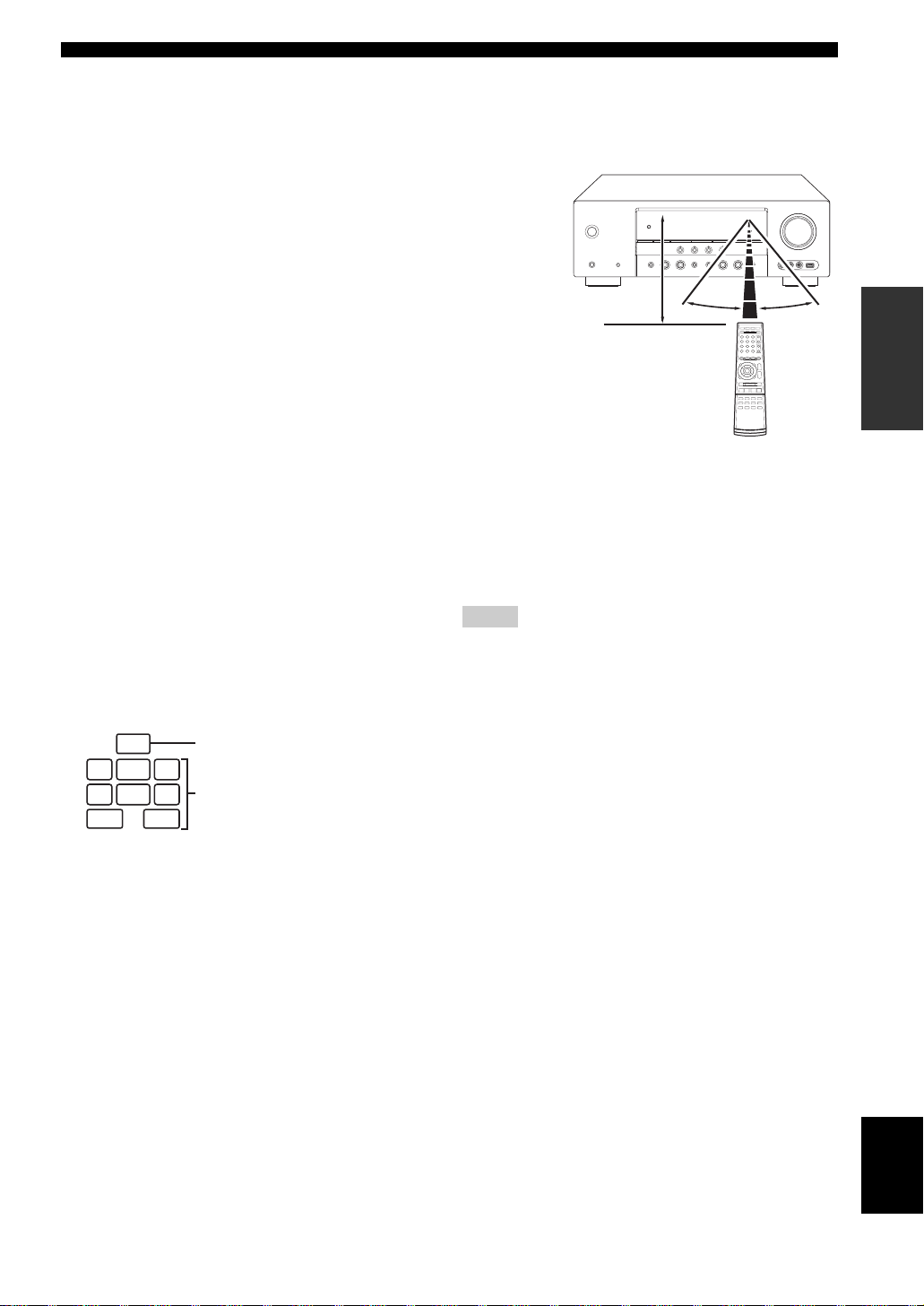
■ Using the remote control
The remote control transmits a directional infrared ray.
Be sure to aim the remote control directly at the remote
control sensor on this unit during operation.
Approximately 6 m (20 ft)
1 Infrared window
Outputs infrared control signals. Aim this window at the
component you want to operate.
y
To set the remote control codes for other components, see
page 73.
Notes
• Do not spill water or other liquids on the remote control.
• Do not drop the remote control.
• Do not leave or store the remote control in the following types
of conditions:
– places of high humidity, such as near a bath
– places of high temperature, such as near a heater or stove
– places of extremely low temperatures
– dusty places
30º 30º
PREPARATION
Input channel indicators
• Indicate the channel components of the current
digital input signal.
• Light up or flash according to the settings of the
speakers when this unit is in the automatic setup
procedure (see page 26) or the speaker level setting
procedure in the “SP LEVEL” (see page 61).
English
25 En
Optimizing the speaker setting for your listening room
Optimizing the speaker setting for your listening room
This unit employs the YPAO (Yamaha Parametric Room Acoustic Optimizer) technology which lets you avoid
troublesome listening-based speaker setup and achieves highly accurate sound adjustments automatically. The supplied
optimizer microphone collects and this unit analyzes the sound your speakers produce in your actual listening
environment.
Using AUTO SETUP
Notes
• Be advised that it is normal for loud test tones to be output
during the “AUTO SETUP” procedure.
• To achieve the best results, make sure the room is as quiet as
possible while the “AUTO SETUP” procedure is in progress. If
there is too much ambient noise, the results may not be
satisfactory.
y
You can run “AUTO SETUP” using the system menu that appears
in the OSD or in the front panel display. This manual uses the
OSD illustrations to explain the “AUTO SETUP” procedure.
1 Make sure of the following check points.
Note
Before starting the automatic setup, check the following
check points.
❏ Speakers are connected appropriately.
❏ Headphones are disconnected from this unit.
❏ This unit and the video monitor are turned on.
❏ This unit is selected as the video input source of
the video monitor.
❏ The connected subwoofer is turned on and the
volume level is set to about half way (or slightly
less).
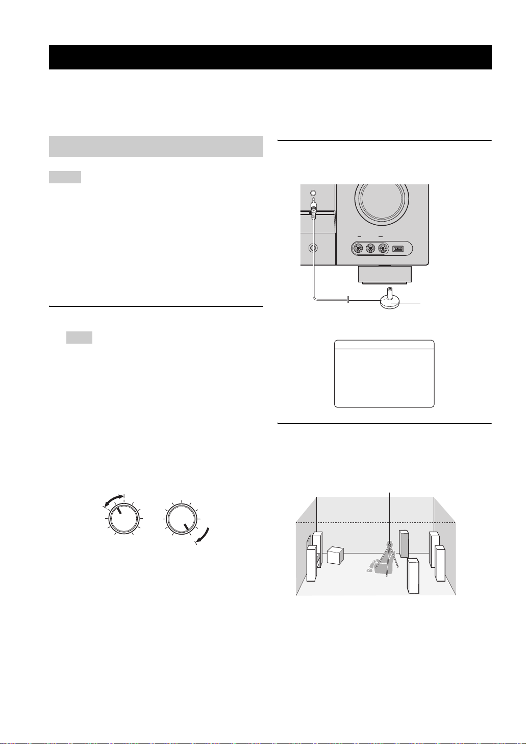
❏ The crossover frequency controls of the
connected subwoofer is set to the maximum.
VOLUME
CROSSOVER
HIGH CUT
2 Connect the supplied optimizer microphone
to the OPTIMIZER MIC jack on the front
panel.
OPTIMIZER MIC
ZONE
CONTROL
/MAN'L
VIDEO AUX USB
AUDIO SELECT
VIDEO L AUDIO R
Optimizer
microphone
The following display appears in the OSD.
AUTO SETUP
SETUP;;;;;;;AUTO
. START
Automatic
Processing
of all item
p
[ ]/[ ]:Up/Down
p
[ENTER]:Start
3 Place the optimizer microphone at your
normal listening position on a flat level
surface with the microphone heading
upward.
Optimizer microphone
MIN
MAX
Controls of a subwoofer (example)
MIN MAX
❏ FRONT A speakers are selected as the front
speaker system (see page 35).
❏ The room is sufficiently quiet.
26 En
y
It is recommended that you use a tripod (etc.) to affix the
optimizer microphone at the same height as your ears would be
when you are seated in your listening position. You can use the
attached screw of a tripod (etc.) to fix the optimizer microphone
to the tripod (etc.).

Optimizing the speaker setting for your listening room
4 Make sure that “SETUP” is set to “AUTO”
and the pointer is pointing at “START”.
y
You can also select the following setup methods. In this
7
case, press
select the one of the following choises and then select
“START”.
k to select “SETUP”, press
Choices: AUTO, RELOAD, UNDO, DEFAULT
• Select “AUTO” to automatically run the entire
“AUTO SETUP” procedure.
• Select “RELOAD” to reload the last “AUTO
SETUP” settings and override the previous
settings.
• Select “UNDO” to undo the last “AUTO SETUP”
settings and restore the previous settings.
• Select “DEFAULT” to reset the “AUTO SETUP”
parameters to the initial factory settings.
Note
“RELOAD” or “UNDO” is available only when you have
previously run “AUTO SETUP” and confirmed the results.
5 Press
7
n to select “START” and then press
7
ENTER to start the setup procedure.
The following message appears in the OSD.
7
l / h to
6 Press
7
ENTER to start the setup
procedure.
This unit starts the auto setup procedure. Loud test
tones are output from each speaker during the auto
setup procedure. Once all items are set, the result
display appears in the OSD.
Notes
• During the auto setup procedure, do not perform any
operation on this unit.
• We recommend getting out of the room while this unit is in
the auto setup procedure. It takes approximately 3 minutes
for this unit to complete the auto setup procedure.
This unit performs the following checks:
Speaker wiring/volume level WIRING/LEVEL
Checks which speakers are connected and the
polarity of each speaker. Also checks and adjusts the
volume level of each speaker.
Speaker distance DISTANCE
Checks the distance of each speaker from the
listening position and adjusts the timing of each
channel.
PREPARATION
NOTICE
Loudtesttonesare
output.
Pleasekeepquiet
orleavetheroom.
Press[ENTER]
Before proceeding next operation
Once you perform the next operation, this unit starts the
automatic setup procedure. For more accurate
measurements, keep quiet and move to the wall where
speakers are not around. We recommend that you leave
the listening room during the automatic setup
procedure.
Speaker size SIZE
Checks the frequency response of each speaker and
sets the appropriate low-frequency crossover for each
channel.
English
27 En
Optimizing the speaker setting for your listening room
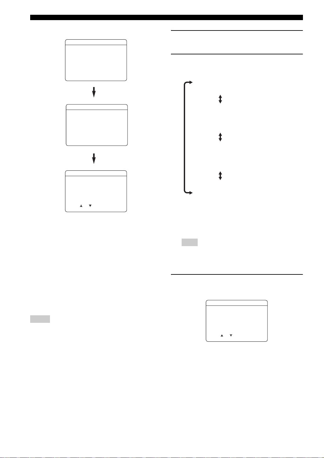
The display changes as follows.
AUTO SETUP
SETUP;;;;;;;AUTO
. START
Automatic
Processing
of all item
p
[ ]/[ ]:Up/Down
p
[ENTER]:Start
7 Press
8
k and 8ENTER to display the
setup results in detail.
8 Press
8
l / h repeatedly to toggle between
the setup result displays.
Results of the speaker
connection and wiring
AUTO SETUP
INITIALIZING
. WIRING/LEVEL
DISTANCE
SIZE
WAITING;;;
;;;;;;;;;;
[
[]:Exit
AUTO SETUP
RESULT
SP : 3/2/0.1
DIST: 3.2/3.5m
LVL : -2/+2dB
. SET CANCEL
>
[ ]/[ ]:Up/Down
[ENTER]:Enter
The results displayed under “RESULT” are as follows.
Number of speakers SP
Displays the number of speakers connected to this unit in
the following order:
Front/Back/Subwoofer
Speaker distance DIST
Displays the speaker distance from the listening position
in the following order:
Closest speaker distance/Farthest speaker distance
Speaker level LVL
Displays the speaker output level in the following order:
Lowest speaker output level/Highest speaker output level
Results of the speaker
distance from the
listening position
Results of the speaker
size
Results of the speaker
output level
y
If you are not satisfied with the results or want to manually
adjust each parameter, run “MANUAL SETUP” (see
page 57).
Note
The distances displayed in the “DISTANCE” results may be
longer than the actual distance depending on the
characteristics of your speakers.
9 Press
8
ENTER to return to the result
display.
AUTO SETUP
Notes
• If “E-9:INTERNAL ERROR” appears during the testing
procedure, restart from step 4.
• If you selected “RELOAD” in step 4, no test tones are output.
• If an error occurs during the “AUTO SETUP” procedure, the
setup procedure is canceled and an error screen appears. For
details, see “If an error screen appears” on page 29.
• When this unit detects potential problems during the “AUTO
SETUP” procedure, “WARNING” and the number of warning
messages appears (see page 29).
28 En
. RESULT
SP : 3/2/0.1
DIST: 3.2/3.5m
LVL : -2/+2dB
SET CANCEL
>
[ ]/[ ]:Up/Down
[ENTER]:Detail
 Loading...