

Yamaha RXV500DB User Manual

AV Receiver
Owner’s Manual
English
Read the supplied booklet “Safety Brochure” before using the unit.

CONTENTS
Accessories . . . . . . . . . . . . . . . . . . . . . . . . . . . . . . . . . . . . . . . . . . . . . . . . . . . . . . 4
FEATURES 5
What you can do with the unit . . . . . . . . . . . . . . . . . . . . . . . . . . . . . . . . . . . . 5
Part names and functions . . . . . . . . . . . . . . . . . . . . . . . . . . . . . . . . . . . . . . . . 7
Front panel . . . . . . . . . . . . . . . . . . . . . . . . . . . . . . . . . . . . . . . . . . . . . . . . . . . . . . . . . . . . . . . . . . . . . . . . . . . . . . . . . . . . . . . . 7
Front display (indicators) . . . . . . . . . . . . . . . . . . . . . . . . . . . . . . . . . . . . . . . . . . . . . . . . . . . . . . . . . . . . . . . . . . . . . . . . . . . 8
Rear panel . . . . . . . . . . . . . . . . . . . . . . . . . . . . . . . . . . . . . . . . . . . . . . . . . . . . . . . . . . . . . . . . . . . . . . . . . . . . . . . . . . . . . . . . . 9
Remote control . . . . . . . . . . . . . . . . . . . . . . . . . . . . . . . . . . . . . . . . . . . . . . . . . . . . . . . . . . . . . . . . . . . . . . . . . . . . . . . . . . . 10
PREPARATIONS 11
General setup procedure . . . . . . . . . . . . . . . . . . . . . . . . . . . . . . . . . . . . . . . . 11
1 Placing speakers . . . . . . . . . . . . . . . . . . . . . . . . . . . . . . . . . . . . . . . . . . . . . . 12
2 Connecting speakers . . . . . . . . . . . . . . . . . . . . . . . . . . . . . . . . . . . . . . . . . . 14
5.1-channel system . . . . . . . . . . . . . . . . . . . . . . . . . . . . . . . . . . . . . . . . . . . . . . . . . . . . . . . . . . . . . . . . . . . . . . . . . . . . . . . 14
Input/output jacks and cables . . . . . . . . . . . . . . . . . . . . . . . . . . . . . . . . . . . 16
3 Connecting a TV . . . . . . . . . . . . . . . . . . . . . . . . . . . . . . . . . . . . . . . . . . . . . . . 17
4 Connecting playback devices . . . . . . . . . . . . . . . . . . . . . . . . . . . . . . . . . . 22
Connecting video devices (such as BD/DVD players) . . . . . . . . . . . . . . . . . . . . . . . . . . . . . . . . . . . . . . . . . . . . . . . 22
Connecting audio devices (such as CD players) . . . . . . . . . . . . . . . . . . . . . . . . . . . . . . . . . . . . . . . . . . . . . . . . . . . . . 25
Connecting to the jacks on the front panel . . . . . . . . . . . . . . . . . . . . . . . . . . . . . . . . . . . . . . . . . . . . . . . . . . . . . . . . . 25
5 Connecting the DAB/FM antenna . . . . . . . . . . . . . . . . . . . . . . . . . . . . . . . 26
6 Connecting to a network . . . . . . . . . . . . . . . . . . . . . . . . . . . . . . . . . . . . . . . 27
7 Connecting recording devices . . . . . . . . . . . . . . . . . . . . . . . . . . . . . . . . . . 28
8 Connecting the power cable . . . . . . . . . . . . . . . . . . . . . . . . . . . . . . . . . . . 28
9 Selecting an on-screen menu language . . . . . . . . . . . . . . . . . . . . . . . . . 29
10 Optimizing the speaker settings automatically (YPAO) . . . . . . . . . 30
Error messages . . . . . . . . . . . . . . . . . . . . . . . . . . . . . . . . . . . . . . . . . . . . . . . . . . . . . . . . . . . . . . . . . . . . . . . . . . . . . . . . . . . . 32
Warning messages . . . . . . . . . . . . . . . . . . . . . . . . . . . . . . . . . . . . . . . . . . . . . . . . . . . . . . . . . . . . . . . . . . . . . . . . . . . . . . . .33
PLAYBACK 34
Basic playback procedure . . . . . . . . . . . . . . . . . . . . . . . . . . . . . . . . . . . . . . . 34
Selecting the input source and favorite settings with one touch
(SCENE) . . . . . . . . . . . . . . . . . . . . . . . . . . . . . . . . . . . . . . . . . . . . . . . . . . . . . . . . 35
Configuring scene assignments . . . . . . . . . . . . . . . . . . . . . . . . . . . . . . . . . . . . . . . . . . . . . . . . . . . . . . . . . . . . . . . . . . . . 35
Selecting the sound mode . . . . . . . . . . . . . . . . . . . . . . . . . . . . . . . . . . . . . . . 36
Enjoying sound field effects (CINEMA DSP) . . . . . . . . . . . . . . . . . . . . . . . . . . . . . . . . . . . . . . . . . . . . . . . . . . . . . . . . .37
Enjoying unprocessed playback . . . . . . . . . . . . . . . . . . . . . . . . . . . . . . . . . . . . . . . . . . . . . . . . . . . . . . . . . . . . . . . . . . . 39
Enjoying pure high fidelity sound (direct playback) . . . . . . . . . . . . . . . . . . . . . . . . . . . . . . . . . . . . . . . . . . . . . . . . .40
Enjoying compressed music with enhanced sound (Compressed Music Enhancer) . . . . . . . . . . . . . . . . . . .41
Enjoying surround sound with headphones (SILENT CINEMA) . . . . . . . . . . . . . . . . . . . . . . . . . . . . . . . . . . . . . . . 41
Listening to DAB radio . . . . . . . . . . . . . . . . . . . . . . . . . . . . . . . . . . . . . . . . . . 42
Preparing the DAB tuning . . . . . . . . . . . . . . . . . . . . . . . . . . . . . . . . . . . . . . . . . . . . . . . . . . . . . . . . . . . . . . . . . . . . . . . . .42
Selecting a DAB radio station for reception . . . . . . . . . . . . . . . . . . . . . . . . . . . . . . . . . . . . . . . . . . . . . . . . . . . . . . . . .42
Registering favorite DAB radio stations (presets) . . . . . . . . . . . . . . . . . . . . . . . . . . . . . . . . . . . . . . . . . . . . . . . . . . . .43
Displaying the DAB information . . . . . . . . . . . . . . . . . . . . . . . . . . . . . . . . . . . . . . . . . . . . . . . . . . . . . . . . . . . . . . . . . . .44
Checking reception strength of each DAB channel label . . . . . . . . . . . . . . . . . . . . . . . . . . . . . . . . . . . . . . . . . . . . 45
Listening to FM radio . . . . . . . . . . . . . . . . . . . . . . . . . . . . . . . . . . . . . . . . . . . 46
Selecting a frequency for reception . . . . . . . . . . . . . . . . . . . . . . . . . . . . . . . . . . . . . . . . . . . . . . . . . . . . . . . . . . . . . . . .46
Registering favorite FM radio stations (presets) . . . . . . . . . . . . . . . . . . . . . . . . . . . . . . . . . . . . . . . . . . . . . . . . . . . . .47
Radio Data System tuning . . . . . . . . . . . . . . . . . . . . . . . . . . . . . . . . . . . . . . . . . . . . . . . . . . . . . . . . . . . . . . . . . . . . . . . . .49
Playing back iPod music . . . . . . . . . . . . . . . . . . . . . . . . . . . . . . . . . . . . . . . . . 50
Connecting an iPod . . . . . . . . . . . . . . . . . . . . . . . . . . . . . . . . . . . . . . . . . . . . . . . . . . . . . . . . . . . . . . . . . . . . . . . . . . . . . . .50
Playback of iPod content . . . . . . . . . . . . . . . . . . . . . . . . . . . . . . . . . . . . . . . . . . . . . . . . . . . . . . . . . . . . . . . . . . . . . . . . . . 51
En 2

Playing back music stored on a USB storage device . . . . . . . . . . . . . . . 54
Connecting a USB storage device . . . . . . . . . . . . . . . . . . . . . . . . . . . . . . . . . . . . . . . . . . . . . . . . . . . . . . . . . . . . . . . . . . 54
Playback of USB storage device contents . . . . . . . . . . . . . . . . . . . . . . . . . . . . . . . . . . . . . . . . . . . . . . . . . . . . . . . . . . 54
Playing back music stored on media servers (PCs/NAS) . . . . . . . . . . . . 57
Media sharing setup . . . . . . . . . . . . . . . . . . . . . . . . . . . . . . . . . . . . . . . . . . . . . . . . . . . . . . . . . . . . . . . . . . . . . . . . . . . . . . 57
Playback of PC music contents . . . . . . . . . . . . . . . . . . . . . . . . . . . . . . . . . . . . . . . . . . . . . . . . . . . . . . . . . . . . . . . . . . . . 57
Listening to Internet radio . . . . . . . . . . . . . . . . . . . . . . . . . . . . . . . . . . . . . . . 60
Playing back iTunes/iPod music via a network (AirPlay) . . . . . . . . . . . 62
Playback of iTunes/iPod music contents . . . . . . . . . . . . . . . . . . . . . . . . . . . . . . . . . . . . . . . . . . . . . . . . . . . . . . . . . . . 62
Viewing the current status . . . . . . . . . . . . . . . . . . . . . . . . . . . . . . . . . . . . . . 64
Switching information on the front display . . . . . . . . . . . . . . . . . . . . . . . . . . . . . . . . . . . . . . . . . . . . . . . . . . . . . . . . 64
Configuring playback settings for different playback sources
(Option menu) . . . . . . . . . . . . . . . . . . . . . . . . . . . . . . . . . . . . . . . . . . . . . . . . . . 65
Option menu items . . . . . . . . . . . . . . . . . . . . . . . . . . . . . . . . . . . . . . . . . . . . . . . . . . . . . . . . . . . . . . . . . . . . . . . . . . . . . . . 65
CONFIGURATIONS 69
Controlling external devices with the remote control . . . . . . . . . . . . . 86
Registering the remote control code for a TV . . . . . . . . . . . . . . . . . . . . . . . . . . . . . . . . . . . . . . . . . . . . . . . . . . . . . . .86
Registering the remote control codes for playback devices . . . . . . . . . . . . . . . . . . . . . . . . . . . . . . . . . . . . . . . . . 87
Resetting remote control codes . . . . . . . . . . . . . . . . . . . . . . . . . . . . . . . . . . . . . . . . . . . . . . . . . . . . . . . . . . . . . . . . . . . . 88
Updating the unit’s firmware via the network . . . . . . . . . . . . . . . . . . . . 89
APPENDIX 90
Frequently asked questions . . . . . . . . . . . . . . . . . . . . . . . . . . . . . . . . . . . . . 90
Troubleshooting . . . . . . . . . . . . . . . . . . . . . . . . . . . . . . . . . . . . . . . . . . . . . . . . 91
Power, system and remote control . . . . . . . . . . . . . . . . . . . . . . . . . . . . . . . . . . . . . . . . . . . . . . . . . . . . . . . . . . . . . . . . .91
Audio . . . . . . . . . . . . . . . . . . . . . . . . . . . . . . . . . . . . . . . . . . . . . . . . . . . . . . . . . . . . . . . . . . . . . . . . . . . . . . . . . . . . . . . . . . . . .93
Video . . . . . . . . . . . . . . . . . . . . . . . . . . . . . . . . . . . . . . . . . . . . . . . . . . . . . . . . . . . . . . . . . . . . . . . . . . . . . . . . . . . . . . . . . . . . .94
DAB radio . . . . . . . . . . . . . . . . . . . . . . . . . . . . . . . . . . . . . . . . . . . . . . . . . . . . . . . . . . . . . . . . . . . . . . . . . . . . . . . . . . . . . . . . .95
FM radio . . . . . . . . . . . . . . . . . . . . . . . . . . . . . . . . . . . . . . . . . . . . . . . . . . . . . . . . . . . . . . . . . . . . . . . . . . . . . . . . . . . . . . . . . . 95
USB and network . . . . . . . . . . . . . . . . . . . . . . . . . . . . . . . . . . . . . . . . . . . . . . . . . . . . . . . . . . . . . . . . . . . . . . . . . . . . . . . . . .96
Error indications on the front display . . . . . . . . . . . . . . . . . . . . . . . . . . . . 97
Configuring various functions (Setup menu) . . . . . . . . . . . . . . . . . . . . . . 69
Setup menu items . . . . . . . . . . . . . . . . . . . . . . . . . . . . . . . . . . . . . . . . . . . . . . . . . . . . . . . . . . . . . . . . . . . . . . . . . . . . . . . . 70
Speaker . . . . . . . . . . . . . . . . . . . . . . . . . . . . . . . . . . . . . . . . . . . . . . . . . . . . . . . . . . . . . . . . . . . . . . . . . . . . . . . . . . . . . . . . . . . 72
HDMI . . . . . . . . . . . . . . . . . . . . . . . . . . . . . . . . . . . . . . . . . . . . . . . . . . . . . . . . . . . . . . . . . . . . . . . . . . . . . . . . . . . . . . . . . . . . . 75
Sound . . . . . . . . . . . . . . . . . . . . . . . . . . . . . . . . . . . . . . . . . . . . . . . . . . . . . . . . . . . . . . . . . . . . . . . . . . . . . . . . . . . . . . . . . . . . 76
ECO . . . . . . . . . . . . . . . . . . . . . . . . . . . . . . . . . . . . . . . . . . . . . . . . . . . . . . . . . . . . . . . . . . . . . . . . . . . . . . . . . . . . . . . . . . . . . . 78
Function . . . . . . . . . . . . . . . . . . . . . . . . . . . . . . . . . . . . . . . . . . . . . . . . . . . . . . . . . . . . . . . . . . . . . . . . . . . . . . . . . . . . . . . . . . 79
Network . . . . . . . . . . . . . . . . . . . . . . . . . . . . . . . . . . . . . . . . . . . . . . . . . . . . . . . . . . . . . . . . . . . . . . . . . . . . . . . . . . . . . . . . . . 81
Language . . . . . . . . . . . . . . . . . . . . . . . . . . . . . . . . . . . . . . . . . . . . . . . . . . . . . . . . . . . . . . . . . . . . . . . . . . . . . . . . . . . . . . . . . 83
Configuring the system settings (ADVANCED SETUP menu) . . . . . . . . 84
ADVANCED SETUP menu items . . . . . . . . . . . . . . . . . . . . . . . . . . . . . . . . . . . . . . . . . . . . . . . . . . . . . . . . . . . . . . . . . . . . 84
Selecting the remote control ID (REMOTE ID) . . . . . . . . . . . . . . . . . . . . . . . . . . . . . . . . . . . . . . . . . . . . . . . . . . . . . . . 84
Switching the video signal type (TV FORMAT) . . . . . . . . . . . . . . . . . . . . . . . . . . . . . . . . . . . . . . . . . . . . . . . . . . . . . . 84
Restoring the default settings (INIT) . . . . . . . . . . . . . . . . . . . . . . . . . . . . . . . . . . . . . . . . . . . . . . . . . . . . . . . . . . . . . . . . 85
Updating the firmware (UPDATE) . . . . . . . . . . . . . . . . . . . . . . . . . . . . . . . . . . . . . . . . . . . . . . . . . . . . . . . . . . . . . . . . . . 85
Checking the firmware version (VERSION) . . . . . . . . . . . . . . . . . . . . . . . . . . . . . . . . . . . . . . . . . . . . . . . . . . . . . . . . . . 85
Glossary . . . . . . . . . . . . . . . . . . . . . . . . . . . . . . . . . . . . . . . . . . . . . . . . . . . . . . . 98
Audio information . . . . . . . . . . . . . . . . . . . . . . . . . . . . . . . . . . . . . . . . . . . . . . . . . . . . . . . . . . . . . . . . . . . . . . . . . . . . . . . . . 98
HDMI and video information . . . . . . . . . . . . . . . . . . . . . . . . . . . . . . . . . . . . . . . . . . . . . . . . . . . . . . . . . . . . . . . . . . . . . . .99
Yamaha technologies . . . . . . . . . . . . . . . . . . . . . . . . . . . . . . . . . . . . . . . . . . . . . . . . . . . . . . . . . . . . . . . . . . . . . . . . . . . .100
Video signal flow . . . . . . . . . . . . . . . . . . . . . . . . . . . . . . . . . . . . . . . . . . . . . . . . . . . . . . . . . . . . . . . . . . . . . . . . . . . . . . . . .101
Information on HDMI . . . . . . . . . . . . . . . . . . . . . . . . . . . . . . . . . . . . . . . . . . 101
HDMI Control . . . . . . . . . . . . . . . . . . . . . . . . . . . . . . . . . . . . . . . . . . . . . . . . . . . . . . . . . . . . . . . . . . . . . . . . . . . . . . . . . . . .101
HDMI signal compatibility . . . . . . . . . . . . . . . . . . . . . . . . . . . . . . . . . . . . . . . . . . . . . . . . . . . . . . . . . . . . . . . . . . . . . . . .103
Reference diagram (rear panel) . . . . . . . . . . . . . . . . . . . . . . . . . . . . . . . . . 104
Trademarks . . . . . . . . . . . . . . . . . . . . . . . . . . . . . . . . . . . . . . . . . . . . . . . . . . . 105
Specifications . . . . . . . . . . . . . . . . . . . . . . . . . . . . . . . . . . . . . . . . . . . . . . . . . 106
Index . . . . . . . . . . . . . . . . . . . . . . . . . . . . . . . . . . . . . . . . . . . . . . . . . . . . . . . . . 108
En 3
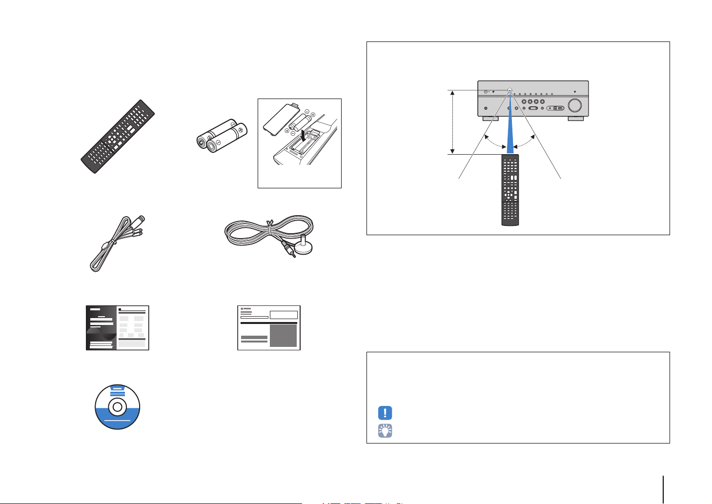
Accessories
Insert the batteries the right
way round.
30° 30°
Within 6 m (20 ft)
Check that the following accessories are supplied with the product.
Remote control Batteries (AAA, R03, UM-4) (x2)
DAB/FM antenna YPAO microphone
Easy Setup Guide Safety Brochure
Operating range of the remote control
• Point the remote control at the remote control sensor on the unit and remain within the operating range
shown below.
CD-ROM (Owner’s Manual)
• Some features are not available in certain regions.
• Due to product improvements, specifications and appearance are subject to change without notice.
• This manual explains operations using the supplied remote control.
• This manual describes all the “iPod”, “iPhone” and “iPad” as the “iPod”. “iPod” refers to “iPod”, “iPhone”
and “iPad”, unless otherwise specified.
• indicates precautions for use of the unit and its feature limitations.
• indicates supplementary explanations for better use.
Accessories En 4
FEATURES
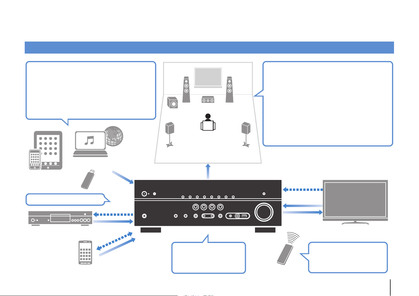
AV receiver (the unit)
Speakers
BD/DVD player
HDMI Control
Audio/Video
Audio/Video
(via HDMI or MHL)
TV remote control
Audio
HDMI Control
Audio
Audio/Video
TV
Sequential operation of a TV,
AV receiver, and BD/DVD
player (HDMI Control)
. p.101
Change the input source
and favorite settings with
one touch (SCENE)
. p.35
Wide variety of supported content
• iPod/iPhone/iPad
. p.50
•USB
. p.54
• Media server (PC/NAS)
. p.57
• Internet radio
. p.60
•AirPlay
. p.62
iPod/iPhone/iPad
USB device
Audio
Network contents
Supports 2- to 5.1-channel speaker system.
Allows you to enjoy your favorite acoustic spaces
in various styles.
• Automatically optimizing the speaker
settings to suit your room (YPAO)
. p.30
• Reproducing stereo or multichannel
sounds with the sound fields like
actual movie theaters and concert
halls (CINEMA DSP)
. p.37
• Enjoying compressed music with
enhanced sound (Compressed Music
Enhancer)
. p.41
3D and 4K signals supported
Smartphone/Tablet
Control
What you can do with the unit
FEATURES ➤ What you can do with the unit En 5
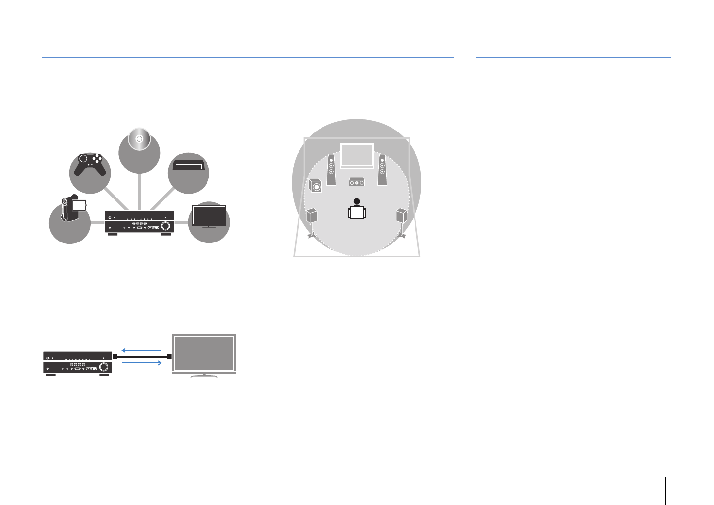
Full of useful functions!
BD/DVD
player
Game
console
Camcorder
TV
Set-top box
HDMI Control
TV audio
Video from
external device
Useful tips
❑ Connecting various devices (p.22)
A number of HDMI jacks and various input/output jacks
on the unit allow you to connect video devices (such as
BD/DVD players), audio devices (such as CD players),
game consoles, camcorders, and other devices.
❑ Playing back TV audio in surround sound
with a single HDMI cable connection
(Audio Return Channel: ARC) (p.17)
When using an ARC -compatible TV, you only need one
HDMI cable to enable video output to the TV, audio input
from the TV, and the transmission of HDMI Control signals.
❑ Easy operation and wireless music
playback from iPhone or Android device
By using the application for smartphone/tablet “AV
CONTROLLER”, you can control the unit from an
iPhone, iPad, iPod touch or Android devices. Visit the
Yamaha website for details.
❑ Creating 3-dimensional sound fields (p.37)
The Virtual Presence Speaker (VPS) function allows you
to create a 3-dimensional sound field in your own room
(CINEMA DSP 3D).
❑ Listening to DAB radio (p.42) and FM radio
(p.46)
The unit is equipped with a built-in DAB/FM tuner. You
can register up to 40 favorite radio stations each for
DAB and FM as presets.
❑ Enjoying pure high fidelity sound (p.40)
When the direct playback mode is enabled, the unit
plays back the selected source with the least circuitry,
which lets you to enjoy Hi-Fi sound quality.
❑ Easy operation with a TV screen
You can operate the iPod or USB storage device, view
information, or easily configure the settings using the
on-screen menu.
❑ Low power consumption
The ECO mode (power saving function) reduces the
unit’s power consumption and helps to create an
eco-friendly home theater system (p.79).
The combination of video/audio input jacks does not
match an external device...
Use “Audio In” in the “Option” menu to change the
combination of video/audio input jacks so that it matches
the output jack(s) of your external device (p.24).
Video and audio are not synchronized...
Use “Lipsync” in the “Setup” menu to adjust the delay
between video and audio output (p.77).
I want to hear audio from the TV speakers...
Use “Audio Output” in the “Setup” menu to select the
output destination of signals input into the unit (p.75).
Your TV speakers may be selected as an output
destination.
I want to use the supplied remote control to operate
external devices…
Register the remote control codes of the external
devices (such as a TV and BD/DVD players) (p.86).
I want to change the on-screen menu language...
Use “Language” in the “Setup” menu to select a
language from English, Japanese, French, German,
Spanish, Russian, Italian and Chinese (p.29).
I want to update the firmware...
Use “Network Update” (p.89) in the “Setup” menu or
“UPDATE” (p.85) in the “ADVANCED SETUP” menu to
update the unit’s firmware.
Many other settings are available that let you to
customize the unit. For details, see the following pages.
• SCENE settings (p.35)
• Sound/video settings and signal information for each
source (p.65)
• Various function settings (p.70)
• System settings (p.84)
FEATURES ➤ What you can do with the unit En 6

Part names and functions
INFO
MEMORY
PRESET
FM DAB
TUNING
CONTROL
TV
BD
DVD
NET
RADIO
INPUT
SCENE
YPAO MIC
PHONES
SILENT
CINEMA
STRAIGHT
VIDEO
DIRECT
AUDIO
VIDEO
VOLUME
AUX
TONE
PROGRAM
5V 2.1A
4:A2 3561 789
B
JDFG
IHCE
Front panel
1 z (power) key
Turns on/off (standby) the unit.
2 Standby indicator
Lights up when the unit is in standby mode under any of the
following conditions.
• HDMI Control is enabled (p.75)
• Standby Through is enabled (p.75)
• Network Standby is enabled (p.82)
• An iPod is being charged (p.50)
3 YPAO MIC jack
For connecting the supplied YPAO microphone (p.30).
4 Remote control sensor
Receives remote control signals (p.4).
5 INFO key
Selects the information displayed on the front display (p.64).
6 MEMORY key
Registers DAB radio stations (p.43) or FM radio stations
(p.47) as preset stations.
7 PRESET keys
Select a preset DAB radio station (p.43) or a preset FM radio
station (p.48).
8 DAB and FM keys
Switch between DAB (p.42) and FM (p.46).
9 TUNING keys
Select a DAB radio station (p.42) or an FM radio frequency
(p.46)
0 Front display
Displays information (p.8).
A DIRECT key
Enables/disables the direct playback mode (p.40).
B PHONES jack
For connecting headphones.
C INPUT keys
Select an input source.
D TONE CONTROL key
Adjusts the high-frequency range and low-frequency range
of output sounds (p.66).
E SCENE keys
Select the registered input source and sound program with
one touch. Also, turns on the unit when it is in standby mode
(p.35).
F PROGRAM keys
Select a sound program or a surround decoder (p.36).
G STRAIGHT key
Enables/disables the straight decode mode (p.39).
H VIDEO AUX jacks
For connecting devices, such as camcorders and game
consoles (p.25).
I USB jack
For connecting a USB storage device (p.54) or an iPod
(p.50).
J VOLUME knob
Adjusts the volume.
FEATURES ➤ Part names and functions En 7
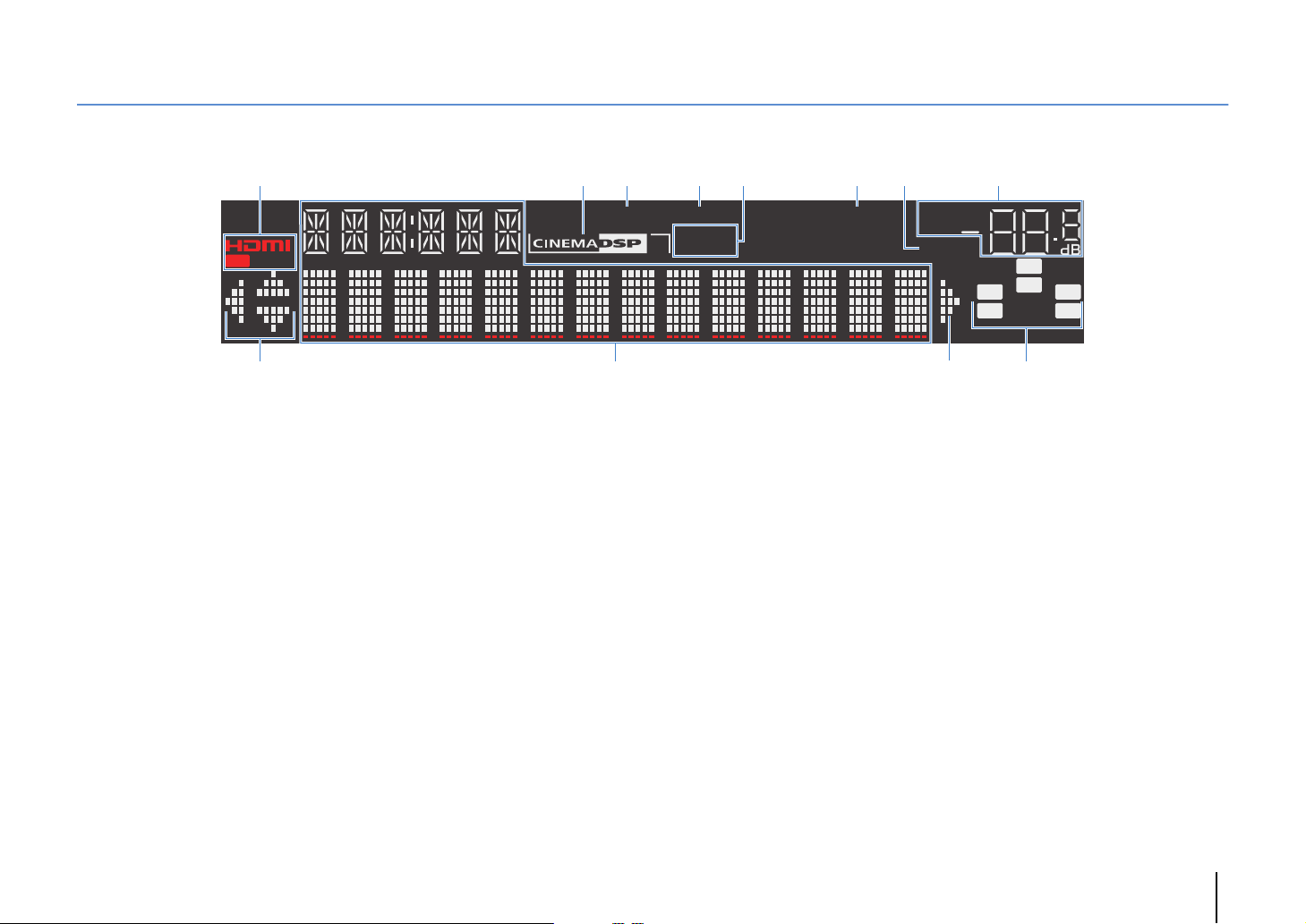
Front display (indicators)
SW
C
LR
SL SR
VOL.
MUTE
ENHANCER
ADAPTIVE DRC
STEREO
3
TUNED
SLEEP
OUT
12346785
9 9: A
1 HDMI
Lights up when HDMI signals are being input or output.
OUT
Lights up when HDMI signals are being output.
2 CINEMA DSP
Lights up when CINEMA DSP (p.37) is working.
CINEMA DSP n
Lights up when CINEMA DSP 3D (p.39) is working.
3 ENHANCER
Lights up when Compressed Music Enhancer (p.41) is
working.
4 ADAPTIVE DRC
Lights up when Adaptive DRC (p.66) is working.
6 SLEEP
Lights up when the sleep timer is on.
7 MUTE
Blinks when audio is muted.
8 Volume indicator
Indicates the current volume.
9 Cursor indicators
Indicate the remote control cursor keys currently operational.
0 Information display
Displays the current status (such as input name and sound
mode name). You can switch the information by pressing
INFO (p.64).
5 STEREO
Lights up when the unit is receiving a stereo FM radio signal.
TUNED
Lights up when the unit is receiving an FM radio station
signal.
A Speaker indicators
Indicate speaker terminals from which signals are output.
L Subwoofer
A Front speaker (L)
S Front speaker (R)
D Center speaker
F Surround speaker (L)
G Surround speaker (R)
FEATURES ➤ Part names and functions En 8
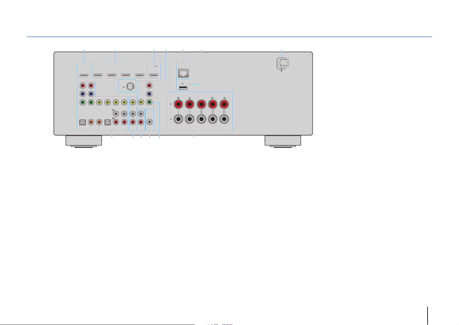
Rear panel
* The area around the video/audio output jacks is
marked in white on the actual product to
prevent improper connections.
21
HDMI 2
HDMI 1
(
)
OUT
HDMI
BD/DVD
ARC
P
R
P
B
Y
COMPONENT
VIDEO
VIDEO
OPTICAL COAXIAL COAXIAL OPTICAL
AV 2
AV 3
AV 1
HDMI 3
ANTENNA
(
)
RADIO
DAB/FM
75
(
)
TV
AV 4
AV
OUT
AV 5
AV 6
8
1 HDMI OUT jack
For connecting to an HDMI-compatible TV and outputting
video/audio signals (p.17). When using ARC, TV audio signal
can also be input through the HDMI OUT jack.
2 HDMI 1–4 jacks
For connecting to HDMI-compatible playback devices and
inputting video/audio signals (p.22).
3 HDMI 5/MHL jack
For connecting to an HDMI- or MHL-compatible playback
device and inputting video/audio signals (p.22).
4 ANTENNA jacks
For connecting to the DAB/FM antenna (p.26).
5 NETWORK jack
For connecting to a network (p.27).
6 DC OUT jack
For supplying power to a Yamaha AV accessory. For details
on connections, refer to the instruction manual of the AV
accessory.
3 5 74 6
HDMI 4
HDMI 5
5V 1A
MHL
COMPONENT
VIDEO
R
P
P
B
Y
MONITOR OUT
SUBWOOFER
PRE OUT
AUDIO
: ACB9
7 Power cabl e
8 AV 1–6 jacks
9 AV OUT jacks
0 AU DIO ja cks
A SUBWOOFER PRE OUT jack
NETWORK
(
)
NET
DC OUT
5V 0.5A
SPEAKERS
FRONT CENTER SURROUND
For connecting to an AC wall outlet (p.28).
For connecting to video/audio playback devices and
inputting video/audio signals (p.22).
For outputting video/audio to a recording device (such as a
VCR) (p.28).
For connecting to an audio playback device and inputting
audio signals (p.25).
For connecting to a subwoofer (with built-in amplifier) (p.14).
B MONITOR OUT jacks
COMPONENT VIDEO jacks:
For connecting to a TV that supports component video and
outputting video signals (p.21).
VIDEO jack:
For connecting to a TV that supports composite video and
outputting video signals (p.21).
C SPEAKERS terminals
For connecting to speakers (p.14).
FEATURES ➤ Part names and functions En 9
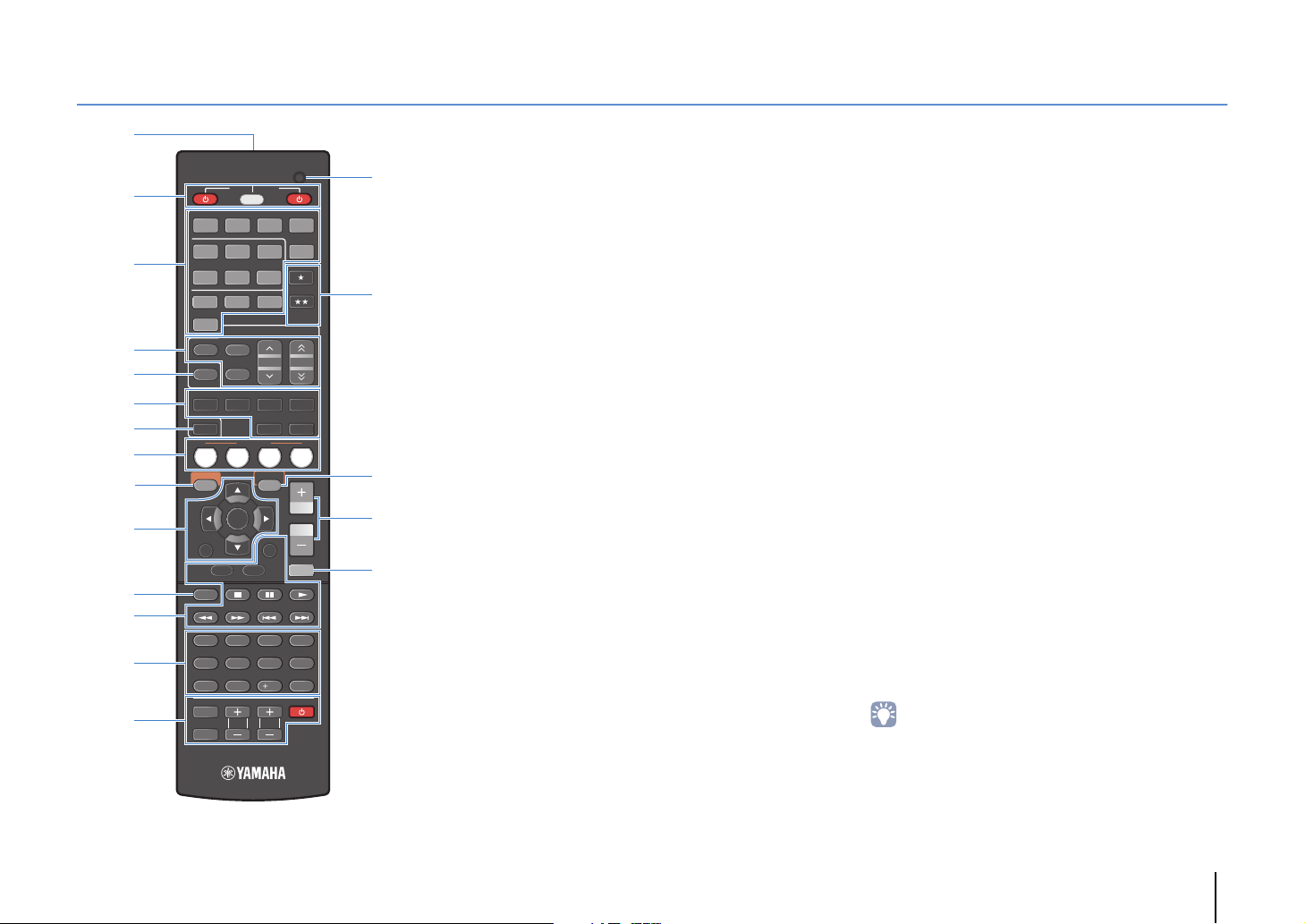
Remote control
E
F
G
H
I
1
3
2
4
5
7
6
8
C
D
9
:
B
A
CODE SET
RECEIVER
SOURCE
HDMI
1 2 3 4
1 2
V-AUX
AUDIO
FM
INFO
MOVIE MUSIC
SLEEP
BD
DVD
SETUP
RETURN
TOP
MENU
MODE
1234
56 87
9 0
INPUT
MUTE
AV
54
USB
TUNER
DAB
PRESET
MEMORY
SUR. DECODE
ENHANCER
SCENE
TV
OPTION
ENTER
DISPLAY
TV
TV VOL TV CH
3
6
NET
NET
POP-UP
MENU
10
STRAIGHT
VOLUME
MHL
5
TUNING
DIRECT
RADIO
MUTE
ENT
1 Remote control signal transmitter
Transmits infrared signals.
2 SOURCE z key
Turns on/off an external device.
SOURCE/RECEIVER key
Changes the device (the unit or external device) that is
operated with the remote control (p.87). You can operate the
unit when this key lights up in orange, and an external device
when this key lights up in green.
RECEIVER z key
Turns on/off (standby) the unit.
3 Input selection keys
Select an input source for playback.
HDMI 1–4 HDMI 1–4 jacks
HDMI 5/MHL HDMI 5/MHL jack
AV 1 – 6 AV 1–6 jacks
V-A UX VIDEO AUX jack (on the front panel)
USB USB jack (on the front panel)
NET NETWORK jack (press repeatedly to select a
desired network source)
AUDIO AUDIO jacks
4 Radio keys
Operate the DAB radio (p.42) or FM radio (p.46).
FM Switches to FM radio.
DAB Switches to DAB radio.
MEMORY Registers DAB/FM radio stations as presets.
PRESET Select a preset DAB/FM radio station.
TUNING Select the DAB radio station or FM radio
frequency.
5 INFO key
Selects the information displayed on the front display (p.64).
6 Sound mode keys
Select a sound mode (p.36).
7 SLEEP key
Switches the unit to standby mode automatically after a
specified period of time has elapsed (sleep timer). Press
repeatedly to set the time (120 min, 90 min, 60 min, 30 min,
off).
8 SCENE keys
Select the registered input source and sound program with
one touch. Also, turns on the unit when it is in standby mode
(p.35).
9 SETUP key
Displays the setup menu (p.69).
0 Menu operation keys
Cursor keys Select a menu or a parameter.
ENTER Confirms a selected item.
RETURN Returns to the previous screen.
A MODE key
Switches between “Stereo” and “Mono” for FM radio
reception (p.46).
Switches the iPod operation modes (p.52).
B External device operation keys
Let you play back and select menus and perform other
operations for external devices (p.87).
C Numeric keys
Let you enter numerical values, such as FM radio
frequencies.
D TV operation keys
Let you select TV input and volume, and perform other TV
operations (p.86).
E CODE SET button
Registers remote control codes of external devices on the
remote control (p.86).
F ★/★★ keys
Change the external device to be controlled without
switching the input source (p.87).
G OPTION key
Displays the option menu (p.65).
H VOLUME keys
Adjust the volume.
I MUTE key
Mutes the audio output.
• To operate external devices with the remote control, register a
remote control code for each device before using (p.86).
FEATURES ➤ Part names and functions En 10

PREPARATIONS
General setup procedure
1 Placing speakers (p.12)
2 Connecting speakers (p.14)
3 Connecting a TV (p.17)
4 Connecting playback devices (p.22)
5 Connecting the DAB/FM antenna (p.26)
6 Connecting to a network (p.27)
7 Connecting recording devices (p.28)
8 Connecting the power cable (p.28)
Selecting an on-screen menu language
9
(p.29)
Optimizing the speaker settings
10
automatically (YPAO) (p.30)
Select the speaker layout for the number of speakers that you are using and place them in your room.
Connect the speakers to the unit.
Connect a TV to the unit.
Connect video devices (such as BD/DVD players) and audio devices (such as CD players) to the unit.
Connect the supplied DAB/FM antenna to the unit.
Connect the unit to a network.
Connect recording devices to the unit.
After all the connections are complete, plug in the power cable.
Select the desired on-screen menu language (default: English).
Optimize the speaker settings, such as volume balance and acoustic parameters, to suit your room
(YPAO).
This completes all the preparations. Enjoy playing movies, music, radio and other content with the unit!
PREPARATIONS ➤ General setup procedure En 11
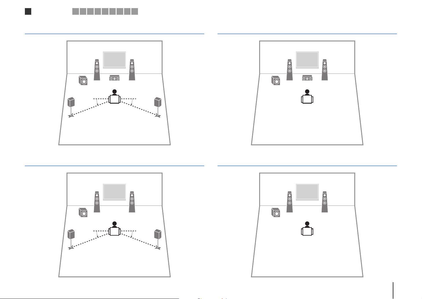
Speaker placement
1
2 3 4 5 6 7 8 9 10
1 Placing speakers
Select the speaker layout for the number of speakers that you are using and place the speakers and subwoofer in your room. This section describes the representative speaker layout
examples.
Caution
• Use speakers with an impedance of at least 6 .
Speaker type Abbr. Function
Front (L) 1
Front (R) 2 ●●●●
Center 3 Produces center channel sounds (such as movie dialogue and vocals). ●●
Surround (L) 4
Surround (R) 5 ●●
Subwoofer 9
Produce front right/left channel sounds (stereo sounds).
Produce surround right/left channel sounds.
Produces LFE (low-frequency effect) channel sounds and reinforces the bass parts of other channels.
This channel is counted as “0.1”.
Speaker system (the number of channels)
5.1 4.1 3.1 2.1
●●●●
●●
●●●●
PREPARATIONS ➤ Placing speakers En 12
45
12
39
10° to 30°10° to 30°
10° to 30°10° to 30°
12
39
Speaker placement
1
2 3 4 5 6 7 8 9 10
5.1-channel system
4.1-channel system
12
3.1-channel system
2.1-channel system
12
9
45
9
PREPARATIONS ➤ Placing speakers En 13
–
+
–
+
FRONT CENTER SURROUND
B
Y
SPEAKERS
SUBWOOFER
PRE OUT
12
3
45
9
The unit (rear)
Speaker connections
1 2
3 4 5 6 7 8 9 10
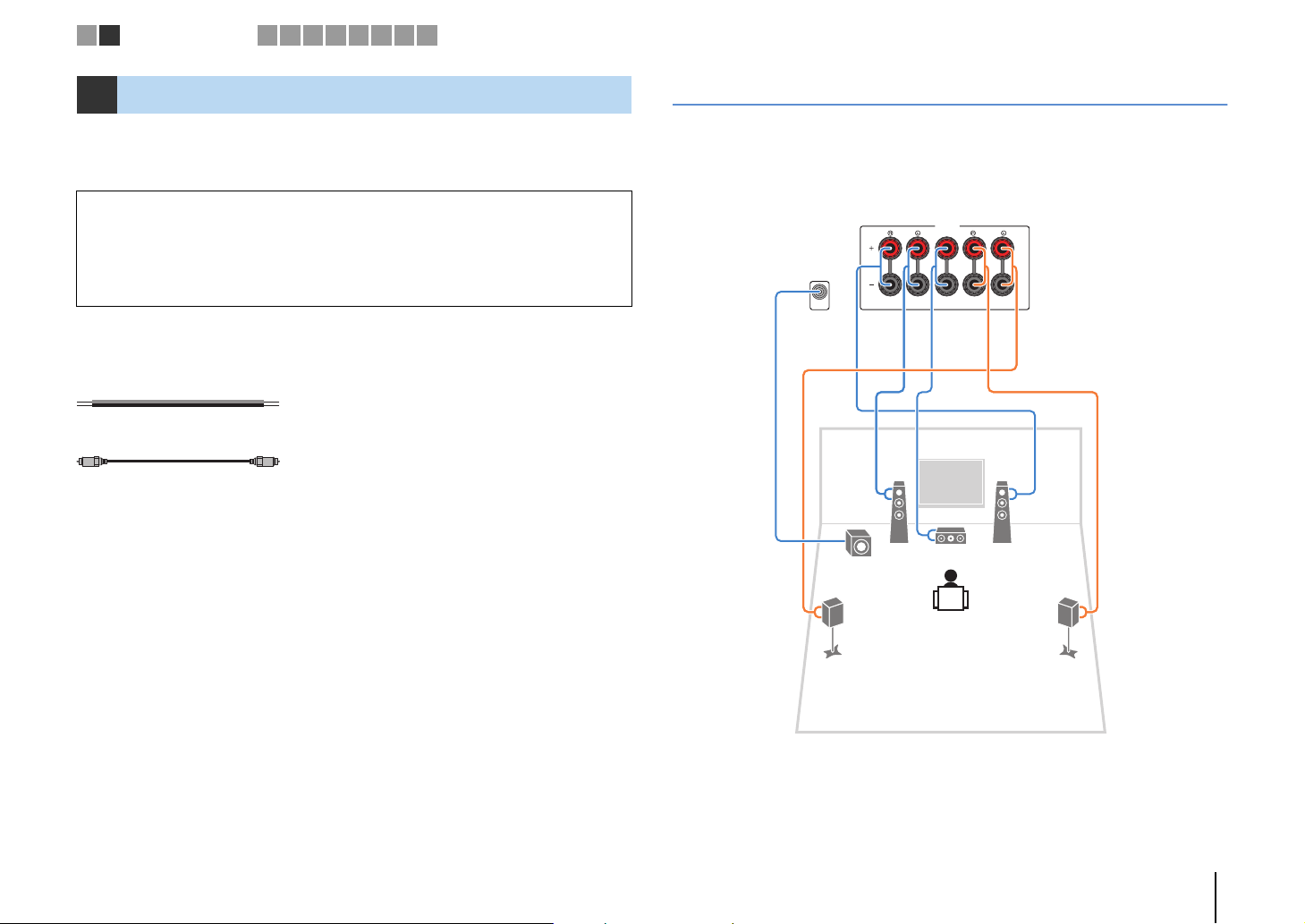
2 Connecting speakers
Connect the speakers placed in your room to the unit. The following diagrams provide
connections for 5.1- system as examples. For other systems, connect speakers while
referring to the connection diagram for the 5.1-channel system.
Caution
• Remove the unit’s power cable from an AC wall outlet and turn off the subwoofer before connecting the
speakers.
• Ensure that the core wires of the speaker cable do not touch one another or come into contact with the
unit’s metal parts. Doing so may damage the unit or the speakers. If the speaker cables short circuit,
“Check SP Wires” will appear on the front display when the unit is turned on.
Cables required for connection
(commercially available)
Speaker cables (x the number of speakers)
Audio pin cable (x1: for connecting a subwoofer)
5.1-channel system
PREPARATIONS ➤ Connecting speakers En 14
FRONT
aa
b
d
c
+ (red)
- (black)
FRONT
a
b
Banana plug
Audio pin cable
Speaker connections
1 2
3 4 5 6 7 8 9 10
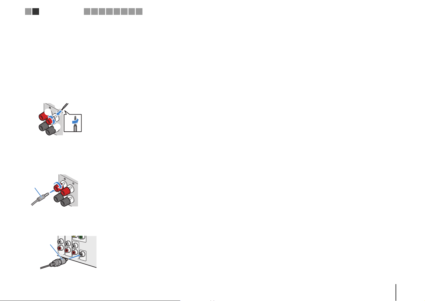
■ Connecting speaker cables
Speaker cables have two wires. One is for connecting the negative (-) terminal of the
unit and the speaker, and the other is for the positive (+) terminal. If the wires are
colored to prevent confusion, connect the black wire to the negative and the other wire
to the positive terminal.
a Remove approximately 10 mm (3/8”) of insulation from the ends of the speaker cable and
twist the bare wires of the cable firmly together.
b Loosen the speaker terminal.
c Insert the bare wires of the cable into the gap on the side (upper right or bottom left) of the
terminal.
d Tighten the terminal.
Using a banana plug
(Australia model only)
a Tighten the speaker terminal.
b Insert a banana plug into the end of the terminal.
■ Connecting the subwoofer (with built-in amplifier)
Use an audio pin cable to connect the subwoofer.
Y
MONITOR OUT
AV6
AV
OUT
SUBWOOFER
AUDIO
PRE OUT
PREPARATIONS ➤ Connecting speakers En 15
Input/output jacks and cables
HDMI cable
HDMI 5
5V
MHL
1A
MHL cable
Component video cable
Video pin cable
AV 4
OPTICAL
(
TV
)
Digital optical cable
Digital coaxial cable
Stereo pin cable
Stereo mini-plug cable
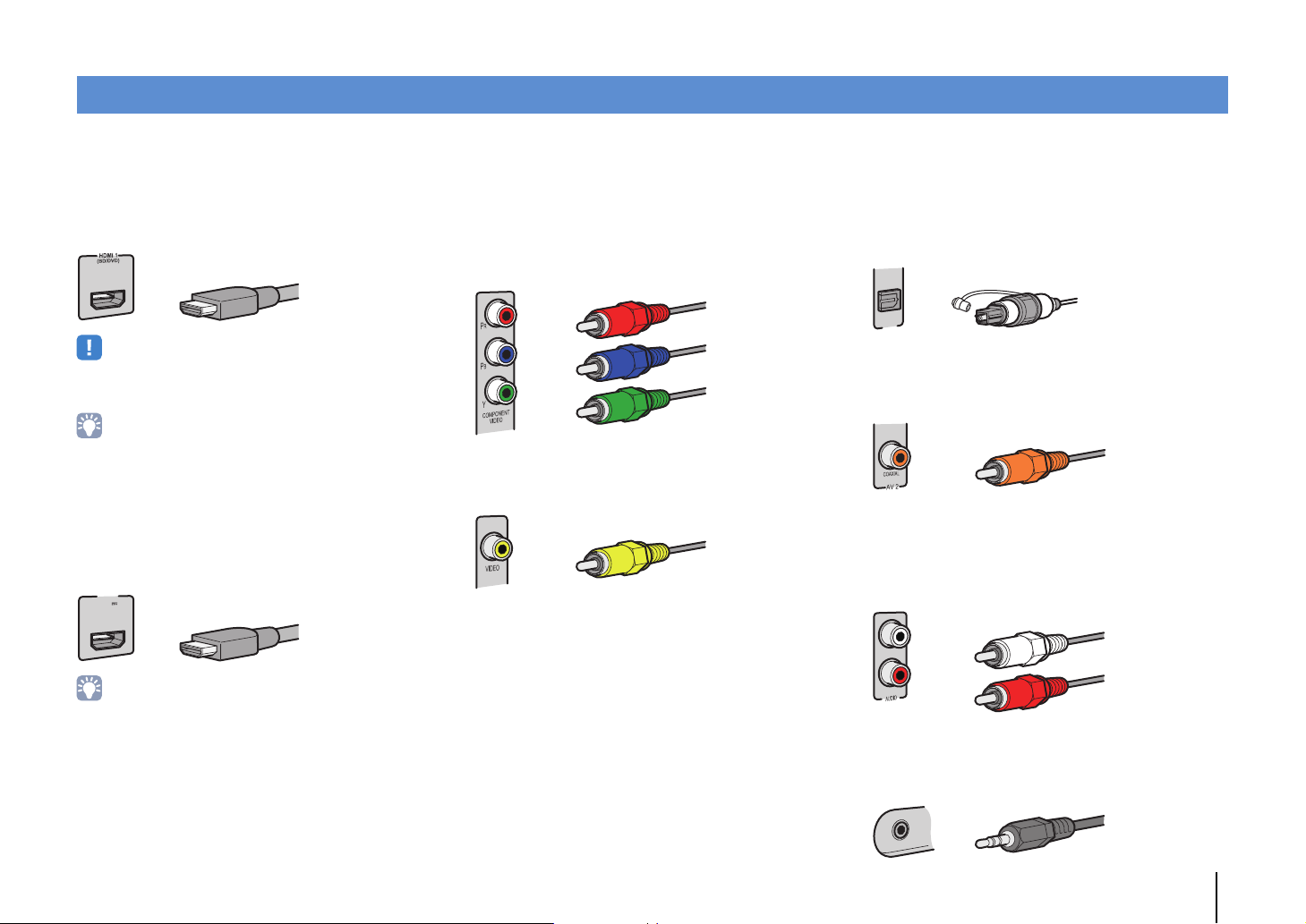
■ Video/audio jacks
❑ HDMI jacks
Transmit digital video and digital sound through a single
jack. Use an HDMI cable.
• Use a 19-pin HDMI cable with the HDMI logo. We recommend using
a cable less than 5.0 m (16.4 ft) long to prevent signal quality
degradation.
• The unit’s HDMI jacks support the HDMI Control, Audio Return
Channel (ARC), and 3D and 4K video transmission (through output)
features.
• Use high speed HDMI cables to enjoy 3D or 4K videos.
❑ HDMI/MHL jack
Transmit digital video and digital sound. Use an MHL
cable.
■ Video jacks
❑ COMPONENT VIDEO jacks
Transmit video signals separated into three
components: luminance (Y), chrominance blue (P
and chrominance red (P
R). Use a component video
cable with three plugs.
❑ VIDEO jacks
Transmit analog video signals. Use a video pin cable.
B),
■ Audio jacks
❑ OPTICAL jacks
Transmit digital audio signals. Use a digital optical
cable. Remove the tip protector (if available) before
using the cable.
❑ COAXIAL jacks
Transmit digital audio signals. Use a digital coaxial
cable.
❑ AUDIO jacks
(Stereo L/R jacks)
Transmit analog stereo audio signals. Use a stereo pin
cable (RCA cable).
• The HDMI 5/MHL jack of the unit supports both HDMI and MHL
connections. Use a cable that matches the jack on your
MHL-compatible mobile device. When connecting an
HDMI-compatible playback device to the jack, use an HDMI cable.
For details on an MHL connection, see “MHL connection” (p.22).
(Stereo mini jack)
Transmits analog stereo audio signals. Use a stereo
mini-plug cable.
PREPARATIONS ➤ Input/output jacks and cables En 16
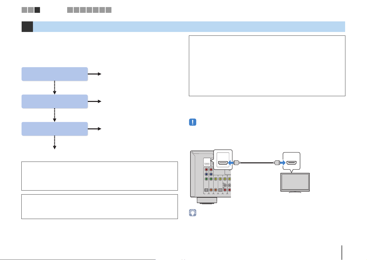
Does your TV support
Audio Return Channel (ARC)?
Does your TV support
HDMI Control?
Does your TV have an
HDMI input jack?
■ Connection Method 3 (p.20)
■ Connection Method 2 (p.19)
■ Connection Method 1 (p.17)
■ Connection Method 4 (p.21)
Yes
Yes
Yes
No
No
No
N
HDMI OUT jack
HDMI input
(ARC-compatible)
The unit (rear)
TV
1 2 3
TV connection
4 5 6 7 8 9 10
3 Connecting a TV
Connect a TV to the unit so that video input to the unit can be output to the TV.
You can also enjoy playback of TV audio on the unit.
The connection method varies depending on the functions and video input jacks
available on your TV.
Refer to the instruction manual of the TV and choose a connection method.
When connecting a video device with an analog video output
• If you will connect any video device to the AV 1–2 (COMPONENT VIDEO) jacks of the unit, you also
need to connect the TV to the MONITOR OUT (COMPONENT VIDEO) jacks (p.21).
• If you will connect any video device to the AV 3–6 (VIDEO) jacks or the VIDEO AUX (VIDEO) of the
unit, you also need to connect the TV to the MONITOR OUT (VIDEO) jack (p.21).
When using a set-top box to watch TV
• Connect the set-top box to the unit in the same way as playback devices (p.22). If you will receive TV
broadcasts only from the set-top box, you do not need to make an audio cable connection between the
TV and the unit or configure the ARC setting.
About HDMI Control
HDMI Control allows you to operate external devices via HDMI. If you connect a TV
that supports HDMI Control to the unit with an HDMI cable, you can control the unit’s
power and volume with the TV’s remote control. You can also control playback
devices (such as an HDMI Control-compatible BD/DVD player) connected to the
unit with an HDMI cable. For details, see “HDMI Control” (p.101).
About Audio Return Channel (ARC)
ARC allows audio signals to travel both ways under HDMI Control. If you connect a
TV that supports HDMI Control and ARC to the unit with a single HDMI cable, you
can output video/audio to the TV or input TV audio to the unit.
■
Connection Method 1 (HDMI Control/ARC-compatible TV)
Connect the TV to the unit with an HDMI cable.
• The following explanation is based on the assumption that you have not changed the “HDMI” parameters
(p.75) in the “Setup” menu.
• Use an HDMI cable that supports ARC.
OUT
HDMI
HDMI 2
HDMI 1
(
OUT
HDMI
BD/DVD
ARC
P
R
P
B
Y
COMPONENT
VIDEO
OPTICAL COAXIAL COAXIAL OPTICAL
AV 2
AV 1
• By connecting a TV to the unit with an HDMI cable, you can navigate the iPod, USB storage device and
network sources, or configure the settings of the unit with the menu displayed on the TV.
HDM
)
ARC
HDMI
ANTEN
(
)
RADIO
DAB/FM
75
VIDEO
(
)
TV
AV 5
AV 6
AV 3
AV 4
HDMI
HDMI
ARC
PREPARATIONS ➤ Connecting a TV En 17
RETURN
O
LUME
L
O
O
N
SETUP
Cursor keys
ENTER
Setup
Speaker
HDMI
Sound
ECO
Function
Network
Language
Configuration
Configuration
HDMI Control
Audio Output
Standby Through
TV Audio Input
Standby Sync
ARC
SCENE
On
Auto
Auto
AV4
Auto
On
Back: RETURN
1 2 3
TV connection
4 5 6 7 8 9 10
❑ Necessary settings
To use HDMI Control and ARC, you need to configure the following settings.
For details on settings and operating your TV, refer to the instruction manual for the TV.
After connecting external devices (such as a TV and playback devices)
1
and the power cable to the unit, turn on the unit, TV, and playback devices.
Configure the settings of the unit.
2
a Check that ARC is enabled on the TV.
b Switch the TV input to display video from the unit.
c Press SETUP.
OPTION
ENTER
DISPLAY
DISP
PTI
VOLUME
V
SETUP
RETURN
d Use the cursor keys to select “HDMI” and press ENTER.
Configure the settings for HDMI Control.
3
a Enable HDMI Control on the TV and playback devices (such as HDMI
Control-compatible BD/DVD player).
b Turn off the TV’s main power and then turn off the unit and playback devices.
c Turn on the unit and playback devices and then turn on the TV’s main power.
d Switch the TV input to display video from the unit.
e Check the following.
On the unit: The input to which the playback device is connected is selected. If not,
select the input source manually.
On the TV: The video from the playback device is displayed.
f Check that the unit is properly synchronized with the TV by turning off the TV or
adjusting the TV volume with the TV remote control.
This completes the necessary settings.
If you select a TV program with the TV remote control, the input source of the unit will be
automatically switched to “AV 4” and the TV audio will be played back on the unit.
If you cannot hear the TV’s audio, check that “ARC” (p.76) in the “Setup” menu is set to
“On”.
• If HDMI Control does not work properly, try turning off and on (or unplugging and then plugging in again)
the devices. It may solve the problem.
• If the unit is not synchronized to the TV’s power operations, check the priority of the audio output setting on
the TV.
• If the audio is interrupted while using ARC, set “ARC” (p.76) in the “Setup” menu to “Off” and use a digital
optical cable to input TV audio to the unit (p.19).
e Press ENTER again.
f Use the cursor keys (q/w) to select “HDMI Control” and the cursor keys (e/r) to
select “On” as shown below.
g Press SETUP.
• “AV 4” is set as TV audio input at the factory. If you have connected any external device to the AV 4 jacks,
use “TV Audio Input” (p.75) in the “Setup” menu to change the TV audio input assignment. To use the
SCENE function (p.35), you also need to change the input assignment for SCENE(TV).
PREPARATIONS ➤ Connecting a TV En 18

AV 1
AV 2
AV 3
AV 5
AV 6
OPTICAL COAXIAL COAXIAL OPTICAL
(
TV
)
COMPONENT
VIDEO
P
B
Y
VIDEO
A
O
AV 4
P
R
ANTENNA
DAB/FM
75
HDMI 1
(
BD/DVD
)
HDMI 2
HDMI 3
HDMI
OUT
ARC
(
RADIO
)
HDMI
HDMI
HDMI
AV 4
(TV)
OPTICAL
OPTICAL
OO
HDMI
OUT
ARC
The unit (rear) HDMI OUT jack
AV 4 (OPTICAL) jack
Audio output
(digital optical)
TV
HDMI input
RETURN
O
LUME
L
O
O
N
SETUP
Cursor keys
ENTER
Setup
Speaker
HDMI
Sound
ECO
Function
Network
Language
Configuration
Configuration
HDMI Control
Audio Output
Standby Through
TV Audio Input
Standby Sync
ARC
SCENE
On
Auto
Auto
AV4
Auto
On
Back: RETURN
1 2 3
TV connection
4 5 6 7 8 9 10
■ Connection Method 2 (HDMI Control-compatible TV)
Connect the TV to the unit with an HDMI cable and a digital optical cable.
• The following explanation is based on the assumption that you have not changed the “HDMI” parameters
(p.75) in the “Setup” menu.
• By connecting a TV to the unit with an HDMI cable, you can navigate the iPod, USB storage device and
network sources, or configure the settings of the unit with the menu displayed on the TV.
❑ Necessary settings
To use HDMI Control, you need to configure the following settings.
For details on settings and operating your TV, refer to the instruction manual for the TV.
After connecting external devices (such as a TV and playback
1
devices) and power cable of the unit, turn on the unit, TV, and
playback devices.
Configure the settings of the unit.
2
a Switch the TV input to display video from the unit.
b Press SETUP.
OPTION
ENTER
DISPLAY
DISP
PTI
VOLUME
V
SETUP
RETURN
c Use the cursor keys to select “HDMI” and press ENTER.
d Press ENTER again.
e Use the cursor keys (q/w) to select “HDMI Control” and the cursor keys (e/r) to
select “On” as shown below.
f Press SETUP.
PREPARATIONS ➤ Connecting a TV En 19

AV 1
AV 2
AV 3
AV 5
AV 6
OPTICAL COAXIAL COAXIAL OPTICAL
(
TV
)
COMPONENT
VIDEO
P
B
Y
VIDEO
A
O
AV 4
P
R
ANTENNA
DAB/FM
75
HDMI 1
(
BD/DVD
)
HDMI 2
HDMI 3
HDMI
OUT
ARC
(
RADIO
)
HDMI
HDMI
HDMI
AV 4
(TV)
OPTICAL
OPTICAL
OO
HDMI
OUT
ARC
The unit (rear) HDMI OUT jack
AV 4 (OPTICAL) jack
Audio output
(digital optical)
TV
HDMI input
1 2 3
TV connection
4 5 6 7 8 9 10
Configure the settings for HDMI Control.
3
a Enable HDMI Control on the TV and playback devices (such as a HDMI
Control-compatible BD/DVD player).
b Turn off the TV’s main power and then turn off the unit and playback devices.
c Turn on the unit and playback devices and then turn on the TV.
d Switch the TV input to display video from the unit.
e Check the following.
On the unit: The input to which the playback device is connected is selected. If not,
select the input source manually.
On the TV: The video from the playback device is displayed.
f Check that the unit is properly synchronized with the TV by turning off the TV or
adjusting the TV volume with the TV remote control.
This completes the necessary settings.
If you select a TV program with the TV remote control, the input source of the unit will be
automatically switched to “AV 4” and the TV audio will be played back on the unit.
• If HDMI Control does not work properly, try turning off and on (or unplugging and then plugging in again)
the devices. It may solve the problem.
• If the unit is not synchronized to the TV’s power operations, check the priority of the audio output setting on
the TV.
• “AV 4” is set as TV audio input at the factory. If you have connected any external device to the AV 4 jacks or
if you want to use another input jack (other than OPTICAL) for connecting the TV, use “TV Audio Input”
(p.75) in the “Setup” menu to change the TV audio input assignment. To use the SCENE function (p.35),
you also need to change the input assignment for SCENE(TV).
■ Connection Method 3 (TV with HDMI input jacks)
Connect the TV to the unit with an HDMI cable and a digital optical cable.
If you switch the input source of the unit to “AV 4” using the AV 4 or SCENE(TV) keys,
the TV audio will be played back on the unit.
• By connecting a TV to the unit with an HDMI cable, you can navigate the iPod, USB storage device and
network sources, or configure the settings of the unit with the menu displayed on the TV.
• If you have connected any external device to the AV 4 jacks or if you want to use another input jack (other
than OPTICAL) for connecting the TV, connect the TV to one of the AV 1–6 and AUDIO jacks. To use the
SCENE function (p.35), you also need to change the input assignment for SCENE(TV).
PREPARATIONS ➤ Connecting a TV En 20
AV 2
AV 3
AV 5
AV 6
COAXIAL COAXIAL OPTICAL
(
TV
)
COMPONENT
VIDEO
VIDEO
AV
MONITOR OUT
OUT
AUDIO
AV 4
P
B
Y
P
R
ANTENNA
DAB/FM
75
HDMI 1
(
BD/DVD
)
HDMI 2
HDMI 3
HDMI 4
(
RADIO
)
SUBWOOFER
PRE OUT
HDMI 5
MHL
5V 1A
AV 4
(TV)
OPTICAL
OPTICAL
PR
PB
Y
COMPONENT
VIDEO
OO
P
R
P
B
Y
P
R
P
B
Y
COMPONENT
VIDEO
MONITOR OUT
PR
PB
Y
The unit (rear)
MONITOR OUT
(COMPONENT VIDEO) jacks
Video input
(component video)
AV 4 (OPTICAL) jack
Audio output
(digital optical)
TV
AV 1
AV 2
AV 3
AV 5
AV 6
OPTICAL COAXIAL COAXIAL OPTICAL
(
TV
)
COMPONENT
VIDEO
COMPONENT
VIDEO
P
B
Y
VIDEO
AV
MONITOR OUT
OUT
AUDIO
AV 4
P
R
P
B
Y
P
R
ANTENNA
DAB/FM
75
HDMI 1
(
BD/DVD
)
HDMI 2
HDMI 3
HDMI 4
HDMI
OUT
ARC
(
RADIO
)
SUBWOOFER
PRE OUT
HDMI 5
MHL
5V
VIDEO
V
V
AV 4
(TV)
OPTICAL
OPTICAL
OO
MONITOR OUT
The unit (rear)
MONITOR OUT
(VIDEO) jack
Video input
(composite video)
Audio output
(digital optical)
TV
AV 4 (OPTICAL) jack
1 2 3
TV connection
4 5 6 7 8 9 10
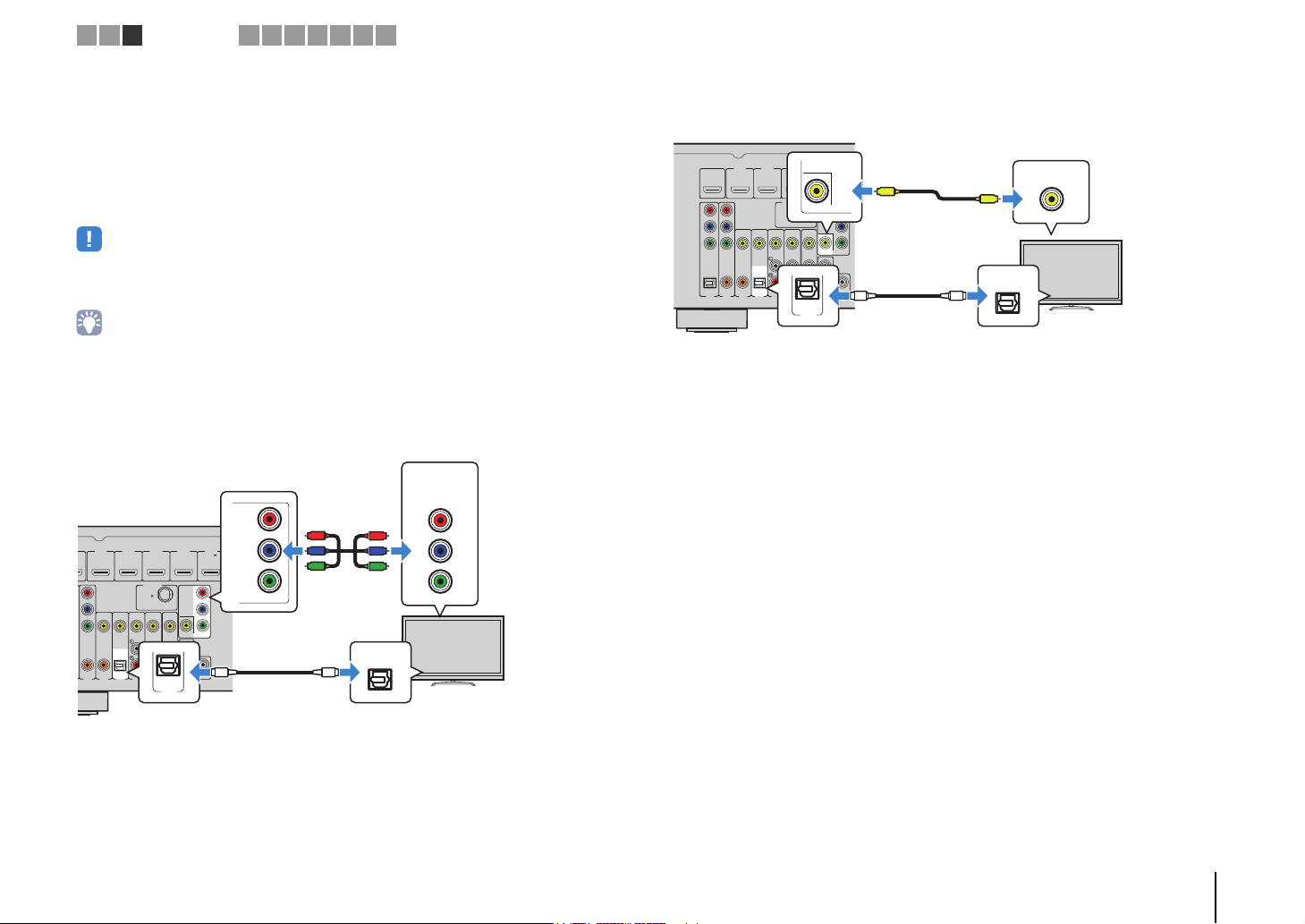
■ Connection Method 4 (TV without HDMI input jacks)
When connecting any video device to the AV 1–2 (COMPONENT VIDEO) jacks of the
unit, connect the TV to the MONITOR OUT (COMPONENT VIDEO) jacks.
When connecting any video device to the AV 3–6 (VIDEO) jacks or the VIDEO AUX
(VIDEO) jack of the unit, connect the TV to the MONITOR OUT (VIDEO) jack.
If you select “AV 4” as the input source by pressing AV 4 or SCENE(TV), the TV audio
will be played back on the unit.
• If you connect your TV to the unit with a cable other than HDMI, video input to the unit via HDMI cannot be
output to the TV.
• Operations with TV screen are available only when your TV is connected to the unit via HDMI.
• If you have connected any external device to the AV 4 jacks or if you want to use another input jack (other
than OPTICAL) for connecting the TV, connect the TV to one of the AV 1–6 and AUDIO jacks. To use the
SCENE function (p.35), you also need to change the input assignment for SCENE(TV).
❑ COMPONENT VIDEO connection (with a component video cable)
❑ VIDEO (composite video) connection (with a video pin cable)
PREPARATIONS ➤ Connecting a TV En 21
AV 1
AV 2
AV 3
AV 5
AV 6
OPTICAL COAXIAL COAXIAL OPTICAL
(
TV
)
COMPONENT
VIDEO
COMPONENT
VIDEO
P
B
Y
VIDEO
AV
MONITOR OUT
OUT
AUDIO
AV 4
P
R
P
B
Y
P
R
ANTENNA
DAB/FM
75
HDMI 1
(
BD/DVD
)
HDMI 2
HDMI 3
HDMI 4
HDMI
OUT
ARC
(
RADIO
)
SUBWOOFER
PRE OUT
HDMI 5
MHL
5V 1A
HDMI
HDMI
HDMI
HDMI 1
(
BD/DVD
)
HDMI 2 HDMI 3 HDMI 4
HDMI 5
MHL
5V 1A
The unit (rear)
HDMI output
Video device
HDMI 1–5 jacks
The unit (rear)
Mobile device
HDMI 5/MHL jack
MHL output
1 2 3 4
Playback device connections
5 6 7 8 9 10
4 Connecting playback devices
The unit is equipped with a variety of input jacks including HDMI input jacks to allow
you to connect different types of playback devices. For information on how to connect
an iPod or a USB storage device, see the following pages.
– Connecting an iPod (p.50)
– Connecting a USB storage device (p.54)
Connecting video devices (such as BD/DVD players)
Connect video devices such as BD/DVD players, set-top boxes (STBs) and game
consoles to the unit. Depending on the video/audio output jacks available on your video
device, choose one of the following connections. We recommend using an HDMI
connection if the video device has an HDMI output jack.
• If the combination of video/audio input jacks available on the unit does not match your video device, change
its combination according to the output jacks of your device (p.24).
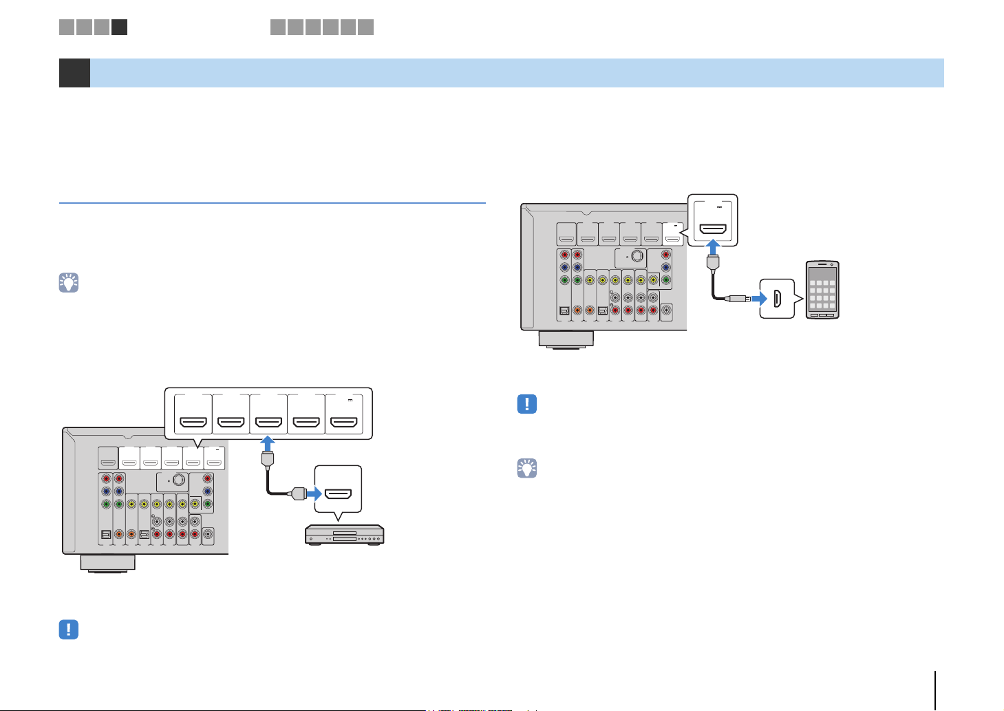
■ HDMI connection
Connect a video device to the unit with an HDMI cable.
If you select the input source by pressing HDMI 1–5, the video/audio played back on
the video device will be output from the unit.
• To watch videos input to the HDMI 1–5 jacks, you need to connect your TV to the HDMI OUT jack of the
unit (p.17 to 20).
❑ MHL connection
Connect an MHL-compatible mobile device (such as smartphones) to the unit with an
MHL cable. You can enjoy full HD videos and multichannel audio sources stored on the
mobile device. The HDMI 5/MHL jack of the unit enables you to input videos and audio
directly from the mobile device to the unit.
HDMI 5
5V 1A
MHL
HDMI 4
HDMI 2
HDMI 1
(
OUT
HDMI
BD/DVD
ARC
P
R
P
B
Y
COMPONENT
VIDEO
OPTICAL COAXIAL COAXIAL OPTICAL
AV 2
AV 1
HDMI 3
)
ANTENNA
(
RADIO
DAB/FM
75
VIDEO
(
)
TV
AV 5
AV 6
AV 3
AV 4
If you select the input source by pressing HDMI 5, the video/audio played back on the
mobile device will be output from the unit.
• To watch videos input to the HDMI 5/MHL jack, you need to connect your TV to the HDMI OUT jack of the
unit (p.17 to 20).
• You need to prepare an MHL cable that match the jack on your mobile device.
• You can operate the mobile device using the menu operation keys, external device operation keys and
numeric keys on the remote control. However, some features may not be compatible, depending on the
mobile device or its application. In this case, operate the mobile device itself.
• If “Standby Through” (p.75) in the “Setup” menu is set to “On”, you can output mobile device videos/audio
to the TV or operate the mobile device using the remote control of the unit even when the unit is in standby
mode.
• The unit supplies power to the mobile device in the following conditions.
– The unit is turned on.
– The unit is in standby mode while “Standby Through” (p.75) in the “Setup” menu is set to “On”.
HDMI 5
5V 1A
MHL
)
COMPONENT
VIDEO
P
R
P
B
Y
MONITOR OUT
SUBWOOFER
AV
PRE OUT
OUT
AUDIO
MHL
MHL
PREPARATIONS ➤ Connecting playback devices En 22
D
The unit (rear)
AV 1–2
(COMPONENTVIDEO)
jacks
Video output
(component video)
Video device
Audio output
(digital optical or digital coaxial)
AV 1 (OPTICAL) jack or
AV 2 (COAXIAL) jack
The unit (rear)
AV 3–6 (VIDEO) jack
Video output
(composite video)
Video device
Audio output
(either digital optical,
digital coaxial, or analog stereo)
Any of AV 3 (COAXIAL) jack,
AV 4 (OPTICAL) jack,
AV 5–6 (AUDIO) jacks
1 2 3 4
Playback device connections
5 6 7 8 9 10
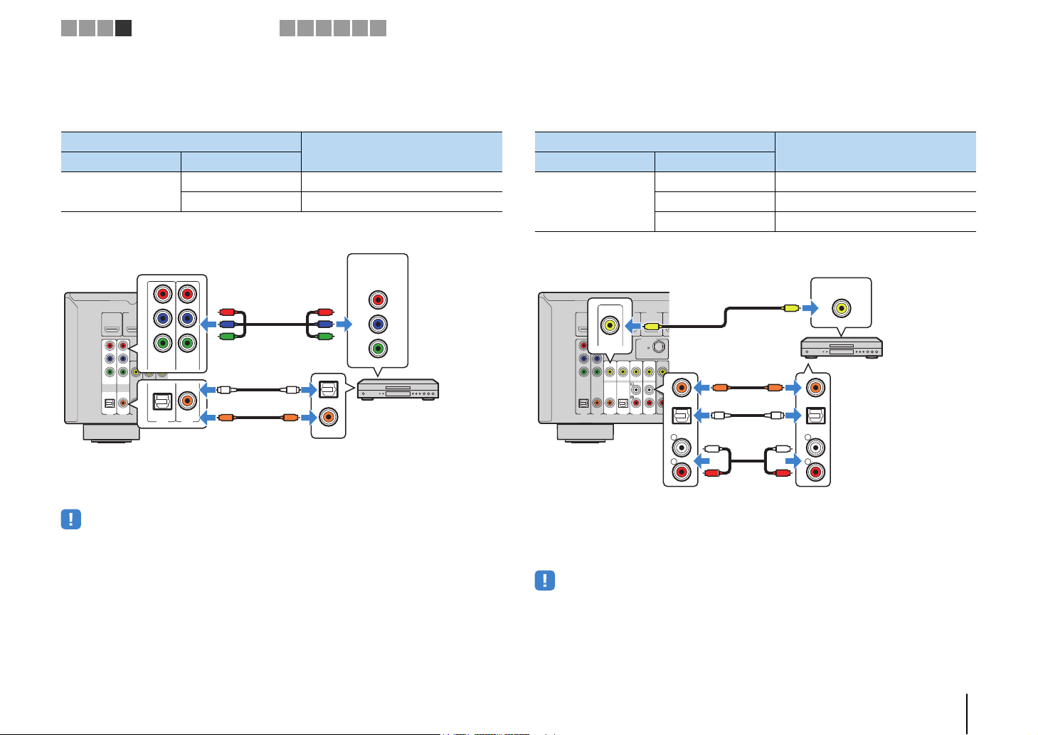
■ Component video connection
Connect a video device to the unit with a component video cable and an audio cable
(digital optical or digital coaxial). Choose a set of input jacks (on the unit) depending on
the audio output jacks available on your video device.
If you select the input source by pressing AV 1–2, the video/audio played back on the
video device will be output from the unit.
• To watch videos input to the AV 1–2 (COMPONENT VIDEO) jacks, you need to connect your TV to the
Output jacks on video device
Video Audio
Component video
HDMI 1
(
)
OUT
HDMI
BD/DVD
ARC
P
R
P
B
Y
COMPONENT
VIDEO
VIDEO
OPTICAL COAXIAL COAXIAL OPTICAL
(
TV
AV 2
AV 3
AV 4
AV 1
P
R
HDMI 2
P
B
Y
COMPONENT
VIDEO
)
OPTICAL COAXIAL
AV 5
AV 1
Digital optical AV 1 (COMPONENT VIDEO + OPTICAL)
Digital coaxial AV 2 (COMPONENT VIDEO + COAXIAL)
R
P
P
B
Y
O
AV 2
C
O
C
MONITOR OUT (COMPONENT VIDEO) jacks of the unit (p.21).
Input jacks on the unit
COMPONENT
VIDEO
P
R
R
P
P
B
P
B
Y
Y
OPTICAL
COAXIAL
■ Composite video connection
Connect a video device to the unit with a video pin cable and an audio cable (digital
coaxial, digital optical, or stereo pin cable). Choose a set of input jacks (on the unit)
depending on the audio output jacks available on your video device.
Output jacks on video device
Video Audio
Digital coaxial AV 3 (VIDEO + COAXIAL)
Composite video
Digital optical AV 4 (VIDEO + OPTICAL)
Analog stereo AV 5–6 (VIDEO + AUDIO)
HDMI 2
VIDEO
VIDEO
AV 3
HDMI 3
)
V
ANTENNA
(
)
RADIO
DAB/FM
75
AV 4
OPTICAL
L
R
COAXIAL
AV
(
)
TV
OUT
AV 5
AV 6
CC
OO
L
R
HDMI 1
(
OUT
HDMI
BD/DVD
ARC
P
R
P
B
Y
COMPONENT
VIDEO
OPTICAL COAXIAL COAXIAL OPTICAL
AV 2
AV 1
If you select the input source by pressing AV 3–6, the video/audio played back on the
video device will be output from the unit.
Input jacks on the unit
VIDEO
V
COAXIAL
OPTICAL
L
L
R
R
• To watch videos input to the AV 3–6 (VIDEO) jacks, you need to connect your TV to the MONITOR OUT
(VIDEO) jack of the unit (p.21).
PREPARATIONS ➤ Connecting playback devices En 23
AV 5
R
L
R
L
AUDIO
L
R
L
R
P
R
P
B
Y
COMPONENT
VIDEO
P
R
P
B
Y
P
R
P
B
Y
AV 2 (COMPONENT VIDEO) jacks
Video output
(component video)
AV 5 (AUDIO) jacks
Video device
Audio output
(analog stereo)
The unit (rear)
RETURN
VOLUME
BD
DVD
ENTER
DISPLAY
OPTION
SETUP
TV
NET
RADIO
RETURN
VO
LUME
BD
DV
D
DISPL
SETUP
TVNET
RADI
O
HDMI
MHL
AV
1 2
3
54
5
1 2 3 4
6
HDMI
MHL
AV
1
3
5
4
5
3
6
Cursor keys
VOL.
AudioIn
VOL.
AudioAV5
1 2 3 4
Playback device connections
5 6 7 8 9 10
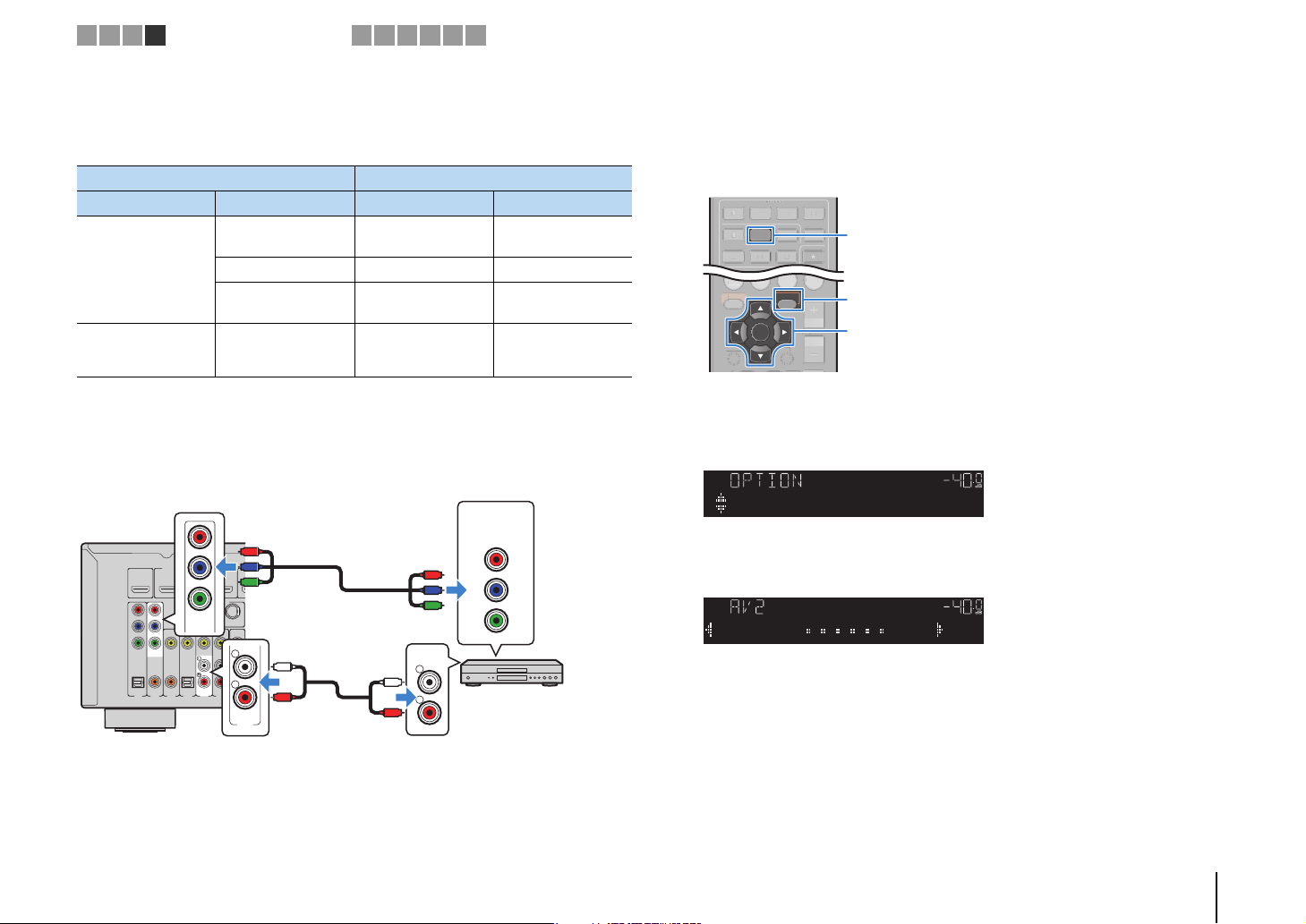
■ Changing the combination of video/audio input jacks
If the combination of video/audio input jacks available on the unit does not match your
video device, change its combination according to the output jacks of your device. You
can connect a video device that has the following video/audio output jacks.
Output jacks on video device Input jacks on the unit
Video Audio Video Audio
HDMI
Component video Analog stereo
❑ Necessary setting
For example, if you have connected a video device to AV 2 (COMPONENT VIDEO) and
AV 5 (AUDIO) jacks of the unit, change the combination setting as follows.
HDMI 1
(
OUT
HDMI
BD/DVD
ARC
P
R
P
B
Y
COMPONENT
VIDEO
OPTICAL COAXIAL COAXIAL OPTICAL
AV 2
AV 1
After connecting external devices (such as a TV and playback
1
devices) and power cable of the unit, turn on the unit.
Press AV 2 to select “AV 2” (video input jack to be used) as the input
2
source.
Digital optical HDMI 1–5
AV 1 (OP T IC A L)
AV 4 (OP T IC A L)
Digital coaxial HDMI 1–5 AV 2–3 (COAXIAL)
Analog stereo HDMI 1–5
AV 1–2
(COMPONENT
VIDEO)
HDMI 2
HDMI 3
)
ANTENNA
(
)
RADIO
DAB/FM
75
VIDEO
AV
(
)
TV
OUT
AV 5
AV 6
AV 3
AV 4
AV 5–6 (AUDIO)
AUDIO
AV 5–6 (AUDIO)
AUDIO
Press OPTION.
3
Use the cursor keys (q/w) to select “Audio In” and press ENTER.
4
Use the cursor keys (e/r) to select “AV 5” (audio input jack to be
5
used).
Press OPTION.
6
This completes the necessary settings.
If you select “AV 2” as the input source by pressing AV 2, the video/audio played back
on the video device will be output from the unit.
AV 2
OPTION
ENTER
PREPARATIONS ➤ Connecting playback devices En 24
O
B
R
Audio output
(either digital optical,
digital coaxial, or analog stereo)
AV 1–6 jacks
AUDIO jacks
The unit (rear)
Audio device
SCENE
Portable audio player
Camcorder
The unit (front)
1 2 3 4
Playback device connections
5 6 7 8 9 10
Connecting audio devices (such as CD players)
Connect audio devices such as CD players and MD players to the unit. Depending on
the audio output jacks available on your audio device, choose one of the following
connections.
Audio output jacks on audio device Audio output jacks on the unit
Digital optical
Digital coaxial AV 2–3 (COAXIAL)
Analog stereo
HDMI 1
(
OUT
HDMI
BD/DVD
ARC
P
R
P
B
Y
COMPONENT
VIDEO
VIDEO
OPTICAL COAXIAL COAXIAL OPTICAL
AV 2
AV 3
AV 1
HDMI 2
)
(
)
TV
AV 4
HDMI 4
HDMI 3
ANTENNA
(
)
RADIO
COMPONENT
VIDEO
DAB/FM
75
P
R
P
B
Y
MONITOR
L
SU
AV
R
P
OUT
AV 5
AV 6
AUDIO
OO
OPTICAL
COAXIAL
CC
L
R
If you select the input source by pressing AV 1–6 or AUDIO, the audio played back on
the audio device will be output from the unit.
AV 1 (OP T ICA L)
AV 4 (OP T ICA L)
AV 5–6 (AUDIO)
OPTICAL
COAXIAL
L
L
R
R
AUDIO
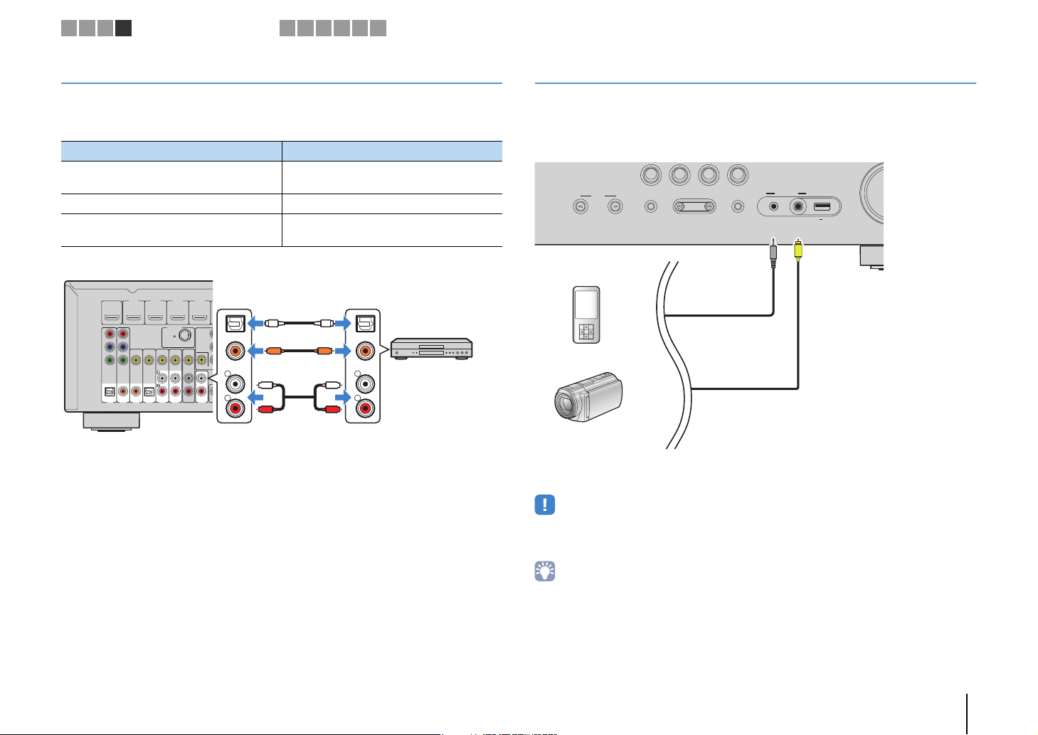
Connecting to the jacks on the front panel
Use the VIDEO AUX jacks on the front panel to temporarily connect devices such as
camcorders and portable audio players to the unit.
Before making a connection, stop playback on the device and turn down the volume on
the unit.
BD
TV
DVD
CONTROL
INPUT
TONE
PROGRAM
If you select “V-AUX” as the input source by pressing V-AUX, the video/audio played
back on the device will be output from the unit.
RADIO
NET
AUX
STRAIGHT
VIDEO
5V 2.1A
VIDEO
AUDIO
V
• To watch videos input to the VIDEO AUX (VIDEO) jack, you need to connect your TV to the MONITOR OUT
(VIDEO) jack of the unit (p.21).
• You need to prepare the video/audio cables that match the output jacks on your device.
• For details on how to connect an iPod or a USB storage device, see “Connecting an iPod” (p.50) or
“Connecting a USB storage device” (p.54).
• When “USB” is selected as the input source, video signals input to the VIDEO AUX (VIDEO) jack are output
from the MONITOR OUT (VIDEO) jack.
PREPARATIONS ➤ Connecting playback devices En 25
FRONT CENTER SURROUND
AV 1
AV 2
AV 3
AV 5
AV 6
OPTICAL COAXIAL COAXIAL OPTICAL
(
TV
)
COMPONENT
VIDEO
COMPONENT
VIDEO
P
B
Y
VIDEO
AV
MONITOR OUT
OUT
AUDIO
AV 4
P
R
P
B
Y
P
R
NETWORK
ANTENNA
DAB/FM
75
SPEAKERS
HDMI 1
(
BD/DVD
)
HDMI 2
HDMI 3
HDMI 4
HDMI
OUT
ARC
(
RADIO
)
SUBWOOFER
PRE OUT
HDMI 5
MHL
DC OUT
5V 0.5A
5V 1A
(
NET
)
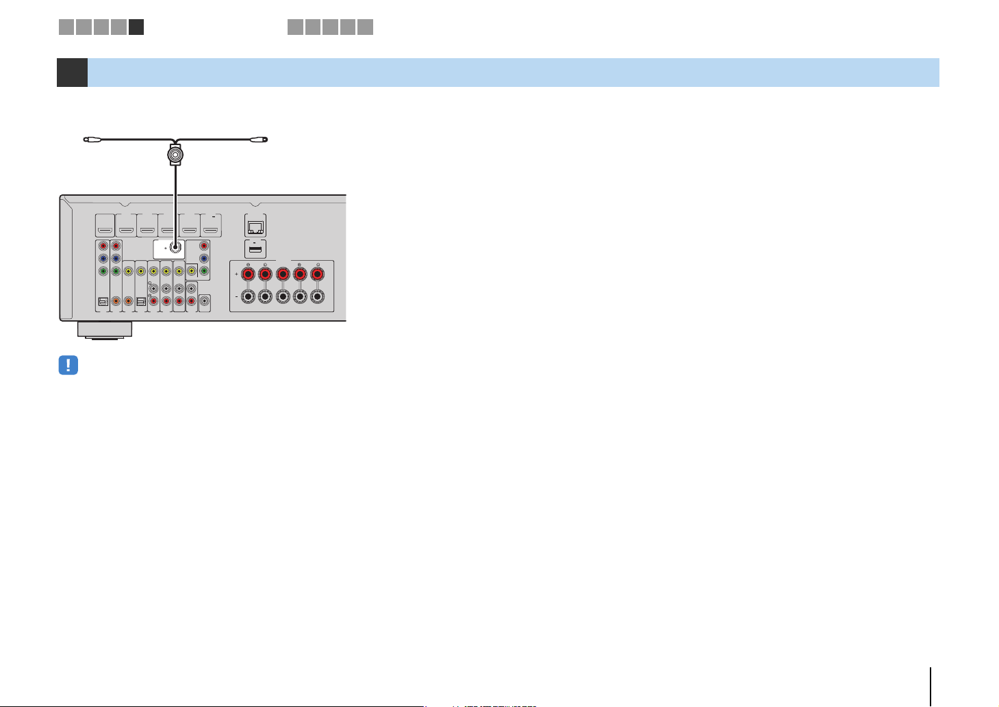
DAB/FM antenna
The unit (rear)
1 2 3 4 5
DAB/FM antenna connection
6 7 8 9 10
5 Connecting the DAB/FM antenna
Connect the supplied DAB/FM antenna to the unit and fix the antenna ends to a wall.
• The antenna should be stretched out horizontally.
• If you cannot obtain good reception on the radio, adjust the height, direction or placement of the DAB/FM
antenna.
PREPARATIONS ➤ Connecting the DAB/FM antenna En 26
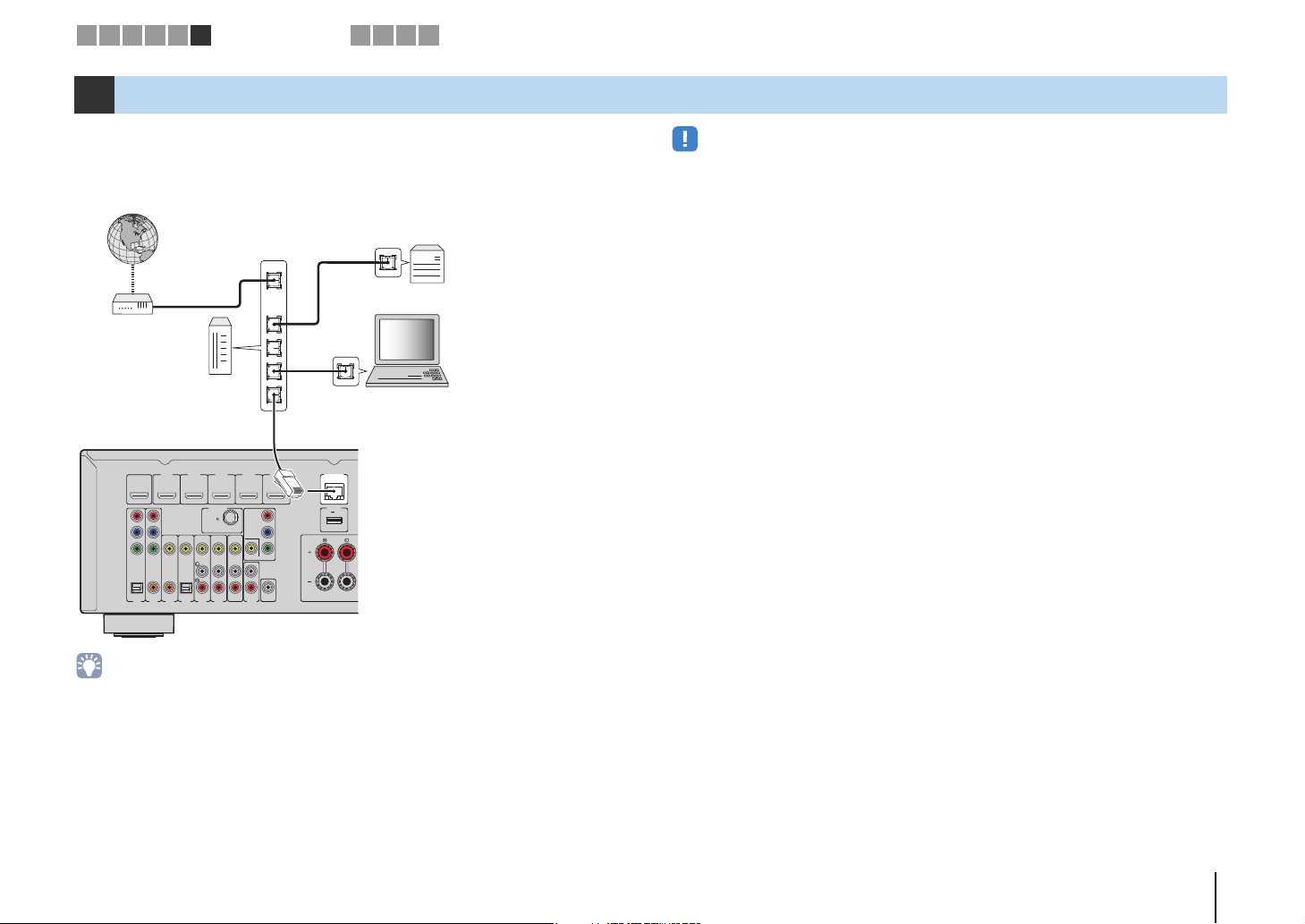
LAN
WAN
Network Attached Storage
(NAS)
Internet
Modem
Router
Network cable
PC
The unit (rear)
1 2 3 4 5 6
Network connections
7 8 9 10
6 Connecting to a network
Connect the unit to your router with a commercially-available STP network cable (CAT-5
or higher straight cable).
You can enjoy Internet radio or music files stored on media servers, such as PCs and
Network Attached Storage (NAS), on the unit.
HDMI 4
HDMI 5
HDMI 3
MHL
)
COMPONENT
VIDEO
R
P
P
B
Y
MONITOR OUT
SUBWOOFER
AV
PRE OUT
OUT
AUDIO
NETWORK
(
)
5V 1A
NET
DC OUT
5V 0.5A
FRONT
HDMI 1
(
OUT
HDMI
BD/DVD
ARC
P
R
P
B
Y
COMPONENT
VIDEO
VIDEO
OPTICAL COAXIAL COAXIAL OPTICAL
AV 2
AV 3
AV 1
HDMI 2
)
ANTENNA
(
RADIO
DAB/FM
75
(
)
TV
AV 5
AV 6
AV 4
• Some security software installed on your PC or the firewall settings of network devices (such as a router)
may block the access of the unit to the network devices or the Internet. In these cases, configure the
security software or firewall settings appropriately.
• Each server must be connected to the same subnet as the unit.
• To use the service via the Internet, broadband connection is strongly recommended.
• If you are using a router that supports DHCP, you do not need to configure any network settings for the unit,
as the network parameters (such as the IP address) will be assigned automatically to it. You only need to
configure the network settings if your router does not support DHCP or if you want to configure the network
parameters manually (p.81).
• You can check whether the network parameters (such as IP address) are properly assigned to the unit in
“Information” (p.81) in the “Setup” menu.
PREPARATIONS ➤ Connecting to a network En 27
The unit (rear)
AV OUT jacks
Video/audio input
Video recording
device
To an AC wall outlet
The unit (rear)
1 2 3 4 5 6 7
Recording device connections8Power cable connection
9 10
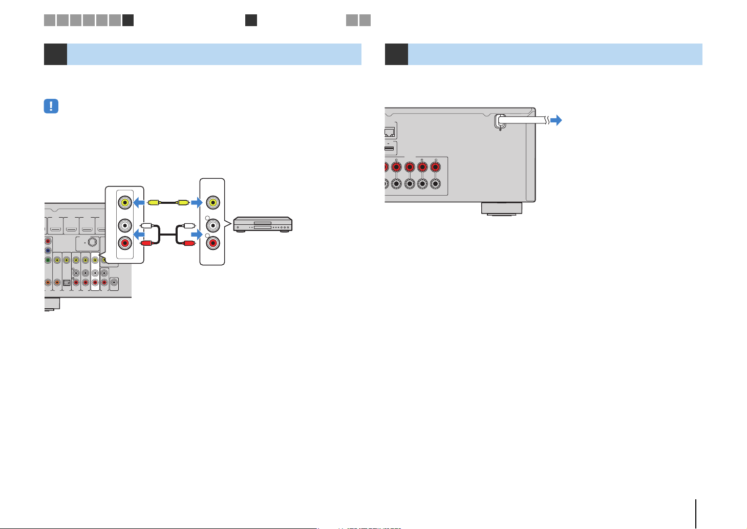
7 Connecting recording devices
You can connect video/audio recording devices to the AV OUT jacks. These jacks
output analog video/audio signals selected as the input.
• To copy video/audio from a video device, connect the video device to the AV 5–6 jacks or VIDEO AUX
(VIDEO/AUDIO) jacks of the unit.
• To copy audio from an audio device, connect the audio device to the AV 5–6 jacks, AUDIO jacks, or VIDEO
AUX (AUDIO) jacks of the unit.
• Be sure to use the AV OUT jacks only for connecting recording devices.
VIDEO
V
V
HDMI 4
HDMI 1
(
)
BD/DVD
VIDEO
COAXIAL COAXIAL OPTICAL
AV 2
AV 3
HDMI 2
HDMI 3
ANTENNA
(
RADIO
DAB/FM
75
(
)
TV
AV 5
AV 6
AV 4
HDMI 5
5V 1A
MHL
)
COMPONENT
VIDEO
P
R
P
B
Y
MONITOR OUT
SUBWOOFER
AV
PRE OUT
OUT
AUDIO
L
R
AV
OUT
L
L
R
R
AUDIO
8 Connecting the power cable
After all the connections are complete, plug in the power cable.
ETWORK
(
)
NET
DC OUT
5V 0.5A
SPEAKERS
FRONT CENTER SURROUND
PREPARATIONS ➤ Connecting recording devices En 28
Setup
Speaker
HDMI
Sound
ECO
Function
Network
Language
English
日本語
Français
Deutsch
Español
Русский
Italiano
中文
Setup
Speaker
HDMI
Sound
ECO
Function
Network
Language
English
日本語
Français
Deutsch
Español
Русский
Italiano
中文
1 2 3 4 5 6 7 8 9
SCENE
RETURN
O
LUME
R
HDMIMHL
TUNER
O
O
RY
SI
C
MUTE
TV
O
LT
TO
P
MEN
U
POP-U
MEN
U
DISPL
AY
R
CO
O
O
N
G
S
S
E
INPUT
MUTE9010
EN
T
658
1
2
3
4
E
O
AUDI
O
1
2
3
V-AUX
5
4
5
3
S
6
CODE SET
DE SET
RECEIVER
RECEIVE
SOURCE
SOURCE
HDMI
1 2 3 4
1 2
3
AV
AV
6
54
V-AUX
AUDIO
MOVIE MUSIC
MOMU
SLEEP
DVD
SETUP
RETURN
TOP
MENU
MODE
MOD
INPUT
MUTE
NET
USB
NTUS
TUNER
FM
DAB
PRESET
PRESET
INFO
INF
MEMORY
MEM
SUR. DECODE
UR
DECOD
ENHANCER
ENHANCE
LEEP
SCENE
BD
TV
NET
OPTION
PTI
ENTER
DISPLAY
POP-UP
MENU
1234
56 87
TV
TV
TV VOL TV CH
V
10
V CH
9 0
P
VOLUME
V
MHL
5
TUNING
TUNIN
STRAIGHT
TRAIGH
DIRECT
DIRECT
RADIO
MUTE
ENT
RECEIVER z RECEIVER z
SETUP
Cursor keys
ENTER
Language setting
10
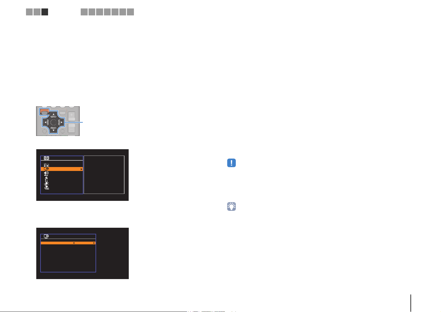
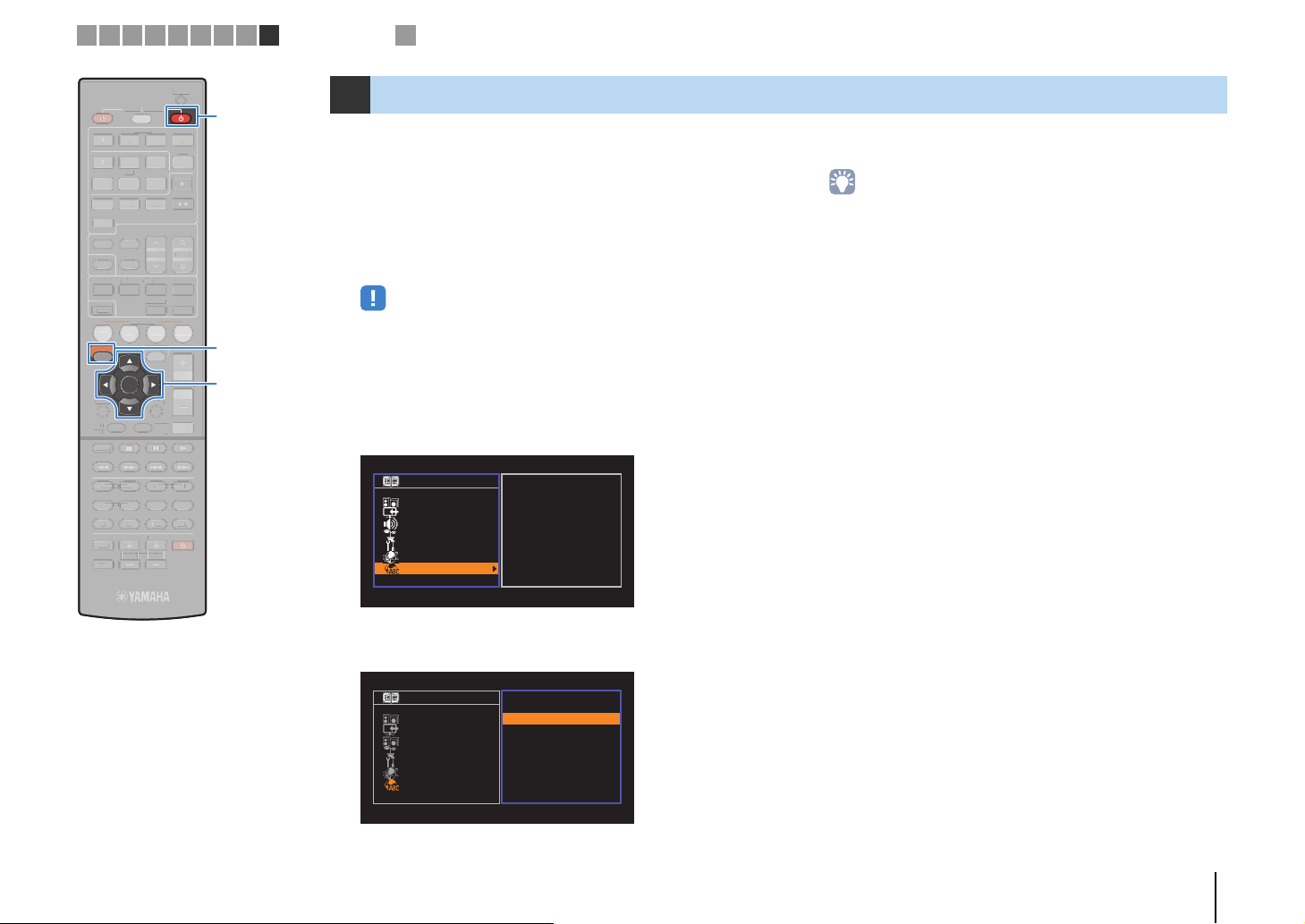
9 Selecting an on-screen menu language
Select the desired on-screen menu language from English
(default), Japanese, French, German, Spanish, Russian, Italian and
Chinese.
Press RECEIVER z to turn on the unit.
1
Turn on the TV and switch the TV input to display
2
video from the unit (HDMI OUT jack).
• Operations with TV screen are available only when your TV is connected to
the unit via HDMI. If not, carry out operations while viewing the front display.
Press SETUP.
3
Use the cursor keys to select “Language” and press
4
ENTER.
To exit from the menu, press SETUP.
6
• The information on the front display is provided in English only.
Use the cursor keys to select the desired language.
5
PREPARATIONS ➤ Selecting an on-screen menu language En 29
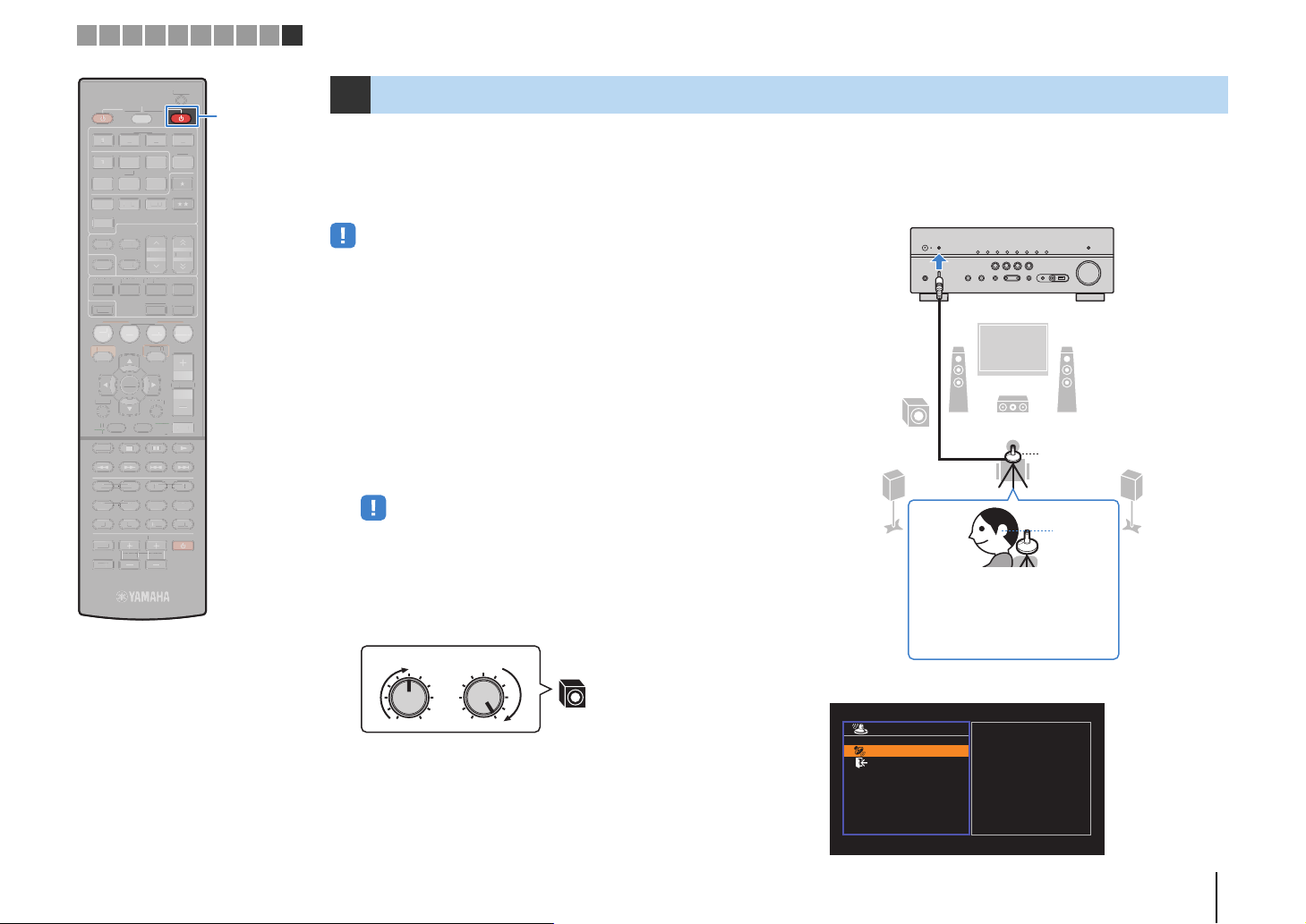
YPAO microphone
Listening
position
Ear height
Place the YPAO microphone at
your listening position (same height
as your ears). We recommend the
use of a tripod as a microphone
stand. You can use the tripod
screws to stabilize the microphone.
The unit (front)
Auto Setup
Start
Exit
Press SETUP key
to Start
1 2 3 4 5 6 7 8 9 10
SCENE
RETURN
O
LUME
R
HDMI
MHL
AV
R
O
O
RY
SI
C
MUTE
ENTER
TV
O
LT
O
P
MEN
U
MEN
U
L
AY
SOURC
R
O
O
N
S
G
S
S
E
INPUT
MUTE9010
EN
T
658
1
2
3
4
E
O
O
1
2
3
US
UX
5
4
5
3
S
6
CODE SET
CODE SET
RECEIVER
RECEIVE
SOURCE
E
HDMI
1 2 3 4
1 2
3
AV
6
54
V-AUX
V-A
AUDIO
AUDI
MOVIE MUSIC
MOMU
SLEEP
DVD
SETUP
RETURN
TOP
T
MENU
MODE
MOD
INPUT
MUTE
NET
USB
TUNE
TUNER
FM
DAB
F
D
B
PRESET
PRESET
INFO
INF
MEMORY
MEM
SUR. DECODE
UR
DECOD
ENHANCER
ENHANCE
LEEP
SCENE
BD
TV
NET
OPTION
ETUP
PTI
ENTER
DISPLAY
DISP
POP-UP
POP-UP
MENU
1234
56 87
TV
TV VOL TV CH
V
10
V CH
9 0
MHL
5
TUNING
TUNIN
STRAIGHT
TRAIGH
DIRECT
DIRECT
RADIO
VOLUME
V
MUTE
ENT
RECEIVER z RECEIVER z
Automatic speaker setup
10 Optimizing the speaker settings automatically (YPAO)
The Yamaha Parametric room Acoustic Optimizer (YPAO) function
detects speaker connections, measures the distances from them to
your listening position(s), and then automatically optimizes the
speaker settings, such as volume balance and acoustic
parameters, to suit your room.
• Please note the following when using YPAO.
– Use YPAO after connecting a TV and speakers to the unit.
– During the measuring process, test tones are output at high volume. Ensure that
the test tones do not frighten small children. Also, refrain from using this function
at night when it may be a nuisance to others.
– During the measuring process, you cannot adjust the volume.
– During the measuring process, keep the room as quiet as possible.
– Do not connect headphones.
Press RECEIVER z to turn on the unit.
1
Turn on the TV and switch the TV input to display
2
video from the unit (HDMI OUT jack).
• Operations with TV screen are available only when your TV is connected to
the unit via HDMI. If not, carry out operations while viewing the front display.
Turn on the subwoofer and set the volume to half. If
3
the crossover frequency is adjustable, set it to
maximum.
Place the YPAO microphone at your listening
4
position (same height as your ears) and connect it
to the YPAO MIC jack on the front panel.
9
45
12
3
VOLUME HIGH CUT
CROSSOVER/
MIN MAXMIN MAX
9
The following screen appears on the TV.
PREPARATIONS ➤ Optimizing the speaker settings automatically (YPAO) En 30
 Loading...