

Yamaha RX-V467, HTR-4063 Service manual
AV RECEIVER
DRAFT
RX-V467/HTR-4063
SERVICE MANUAL
IMPORTANT NOTICE
This manual has been provided for the use of authorized YAMAHA Retailers and their service personnel.
It has been assumed that basic service procedures inherent to the industry, and more specifi cally YAMAHA Products, are already known
and understood by the users, and have therefore not been restated.
WARNING:
IMPORTANT:
The data provided is believed to be accurate and applicable to the unit(s) indicated on the cover. The research, engineering, and service
departments of YAMAHA are continually striving to improve YAMAHA products. Modifications are, therefore, inevitable and
specifi cations are subject to change without notice or obligation to retrofi t. Should any discrepancy appear to exist, please contact the
distributor's Service Division.
WARNING:
IMPORTANT:
Failure to follow appropriate service and safety procedures when servicing this product may result in personal injury,
destruction of expensive components, and failure of the product to perform as specifi ed. For these reasons, we advise
all YAMAHA product owners that any service required should be performed by an authorized YAMAHA Retailer or
the appointed service representative.
The presentation or sale of this manual to any individual or fi rm does not constitute authorization, certifi cation or
recognition of any applicable technical capabilities, or establish a principle-agent relationship of any form.
Static discharges can destroy expensive components. Discharge any static electricity your body may have
accumulated by grounding yourself to the ground buss in the unit (heavy gauge black wires connect to this buss).
Turn the unit OFF during disassembly and part replacement. Recheck all work before you apply power to the unit.
■ CONTENTS
TO SERVICE PERSONNEL ............................................2
FRONT PANELS ............................................................. 3
REAR PANELS ...........................................................4–9
REMOTE CONTROL PANEL .......................................... 9
SPECIFICATIONS /
INTERNAL VIEW .......................................................... 16
SERVICE PRECAUTIONS /
DISASSEMBLY PROCEDURES /
UPDATING FIRMWARE /
ファームウェアの書き込み
SELF-DIAGNOSTIC FUNCTION /
ダイアグ(自己診断機能)
101169
参考仕様
................................. 10–15
サービス時の注意事項
分解手順
.....................................20–33
.......................................34–63
........... 17–19
Copyright © 2010 All rights reserved.
This manual is copyrighted by YAMAHA and may not be copied or
redistributed either in print or electronically without permission.
.....16
DISPLAY DATA .......................................................64–65
IC DATA ...................................................................66–75
PIN CONNECTION DIAGRAMS ............................. 76–77
BLOCK DIAGRAMS ................................................78–81
PRINTED CIRCUIT BOARDS .................................82–99
SCHEMATIC DIAGRAMS .................................... 101–111
REPLACEMENT PARTS LIST ............................ 113–129
REMOTE CONTROL ........................................... 130–133
ADVANCED SETUP / ......................................... 134–135
本機の設定を変更する
.................................................. 136
P.O.Box 1, Hamamatsu, Japan
'10.04
RX-V467/HTR-4063

RX-V467/HTR-4063
DRAFT
■ TO SERVICE PERSONNEL
1. Critical Components Information
Components having special characteristics are marked ⚠ and
must be replaced with parts having specifications equal to those
originally installed.
2. Leakage Current Measurement (For 120V Models Only)
When service has been completed, it is imperative to verify
that all exposed conductive surfaces are properly insulated
from supply circuits.
• Meter impedance should be equivalent to 1500 ohms shunted
by 0.15 μF.
For U model
“CAUTION”
“F3701: FOR CONTINUED PROTECTION AGAINST RISK OF FIRE, REPLACE ONLY WITH SAME TYPE 6A,
125V FUSE.”
For C model
CAUTION
F3701: REPLACE WITH SAME TYPE 6A, 125V FUSE.
ATTENTION
F3701: UTILISER UN FUSIBLE DE RECHANGE DE MÉME TYPE DE 6A, 125V.
WALL
OUTLET
• Leakage current must not exceed 0.5mA.
• Be sure to test for leakage with the AC plug in both polarities.
EQUIPMENT
UNDER TEST
INSULATING
TABLE
AC LEAKAGE
TESTER OR
EQUIVALENT
WARNING: CHEMICAL CONTENT NOTICE!
This product contains chemicals known to the State of California to cause cancer, or birth defects or other reproductive
harm.
DO NOT PLACE SOLDER, ELECTRICAL/ELECTRONIC OR PLASTIC COMPONENTS IN YOUR MOUTH FOR ANY REASON
WHATSOEVER!
Avoid prolonged, unprotected contact between solder and your skin! When soldering, do not inhale solder fumes or
expose eyes to solder/flux vapor!
If you come in contact with solder or components located inside the enclosure of this product, wash your hands before
handling food.
About lead free solder /
All of the P.C.B.s installed in this unit and solder joints are
soldered using the lead free solder.
Among some types of lead free solder currently available,
it is recommended to use one of the following types for
the repair work.
• Sn + Ag + Cu (tin + silver + copper)
• Sn + Cu (tin + copper)
• Sn + Zn + Bi (tin + zinc + bismuth)
Caution:
As the melting point temperature of the lead free solder
is about 30°C to 40°C (50°F to 70°F) higher than that of
the lead solder, be sure to use a soldering iron suitable
to each solder.
RX-V467/HTR-4063
無鉛ハンダについて
本機に搭載されているすべての基板およびハンダ付けに
よる接合部は無鉛ハンダでハンダ付けされています。
無鉛ハンダにはいくつかの種類がありますが、修理時に
は下記のような無鉛ハンダの使用を推奨します。
Sn+Ag+Cu(錫+銀+銅)
Sn+Cu(錫 + 銅)
Sn+Zn+Bi(錫 + 亜鉛 + ビスマス)
注意:
無鉛ハンダの融点温度は通常の鉛入りハンダに比べ 30 〜
40℃程度高くなっていますので、それぞれのハンダに合っ
たハンダごてをご使用ください。
2
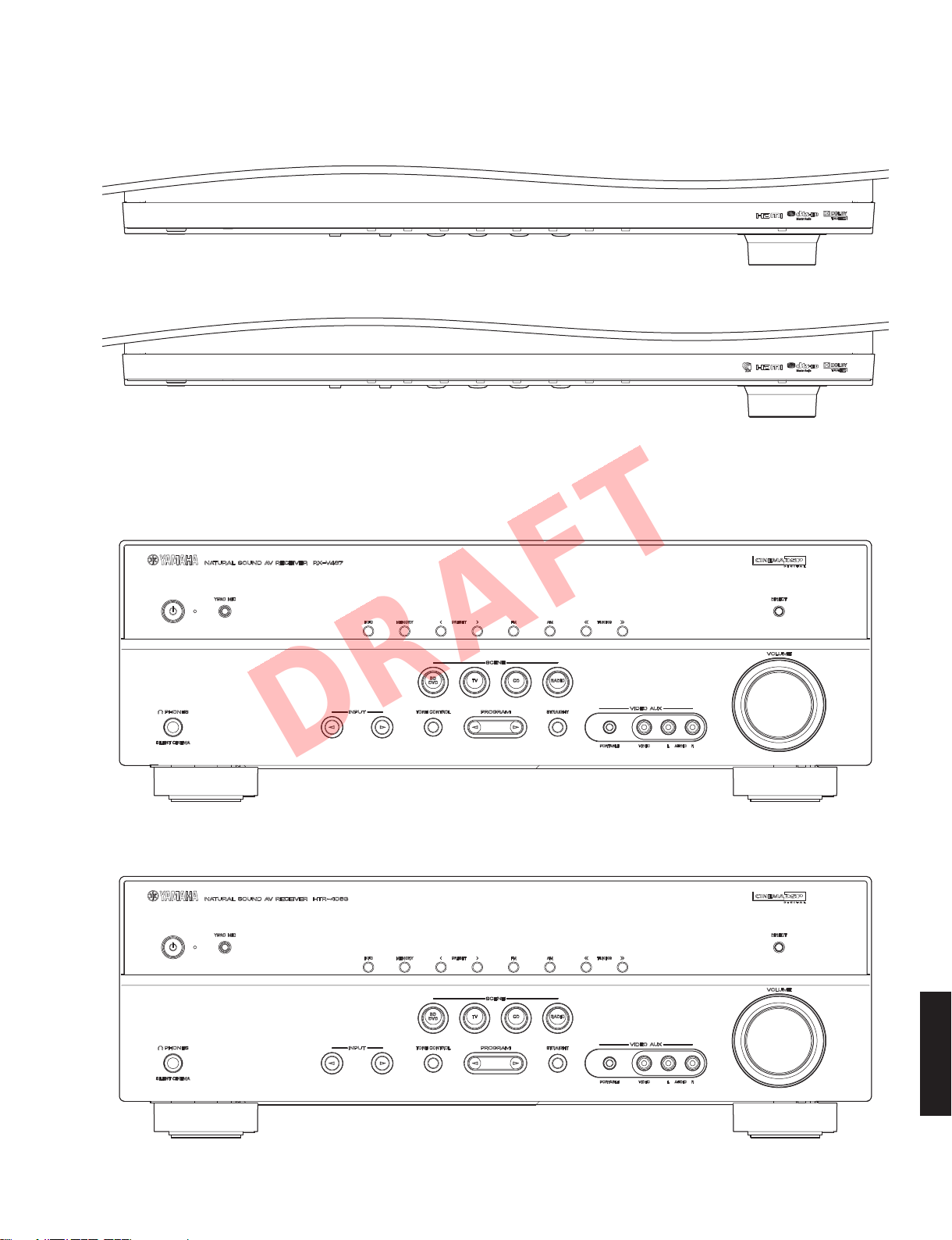
■ FRONT PANELS
DRAFT
Top view
U, C, R, T, K, A, B, G, F, L, models
J model
RX-V467/HTR-4063
Front view
RX-V467
HTR-4063
RX-V467/HTR-4063
3
RX-V467/HTR-4063
DRAFT
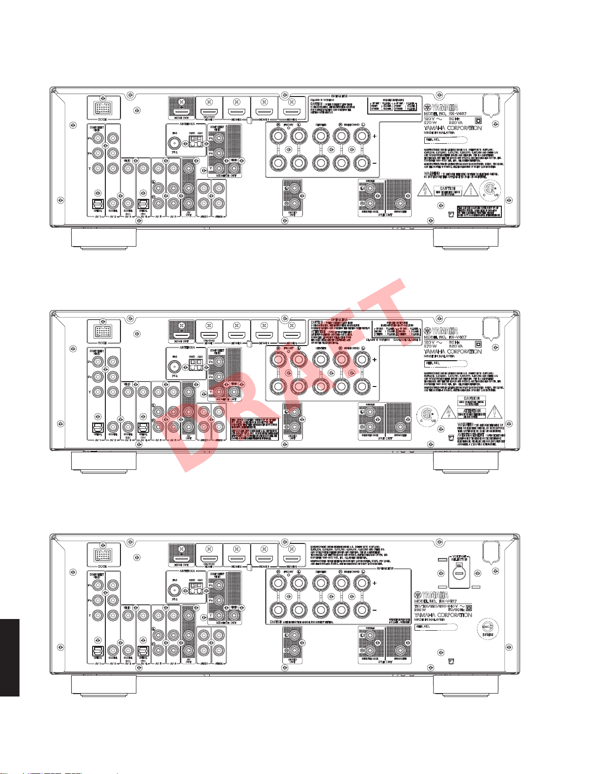
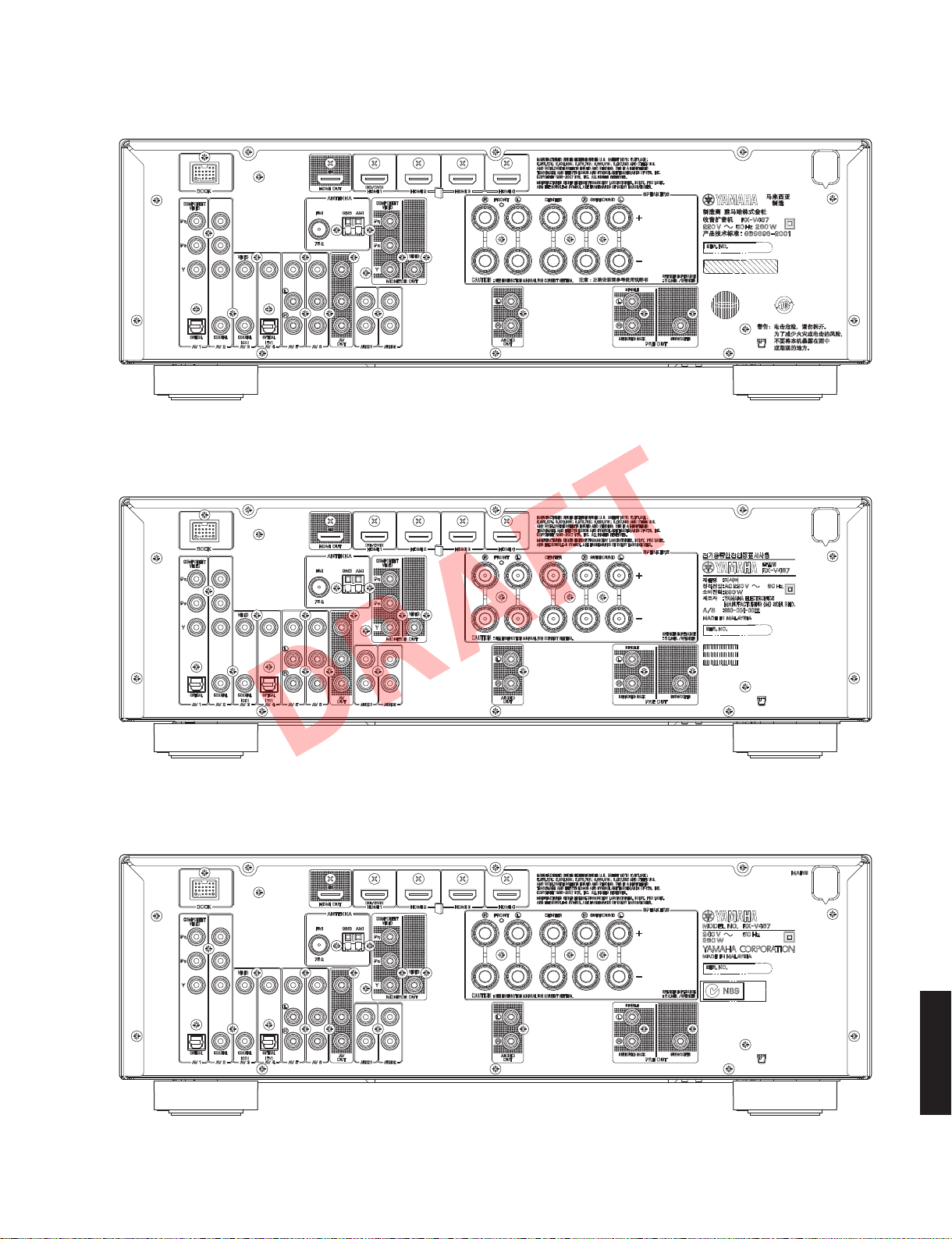
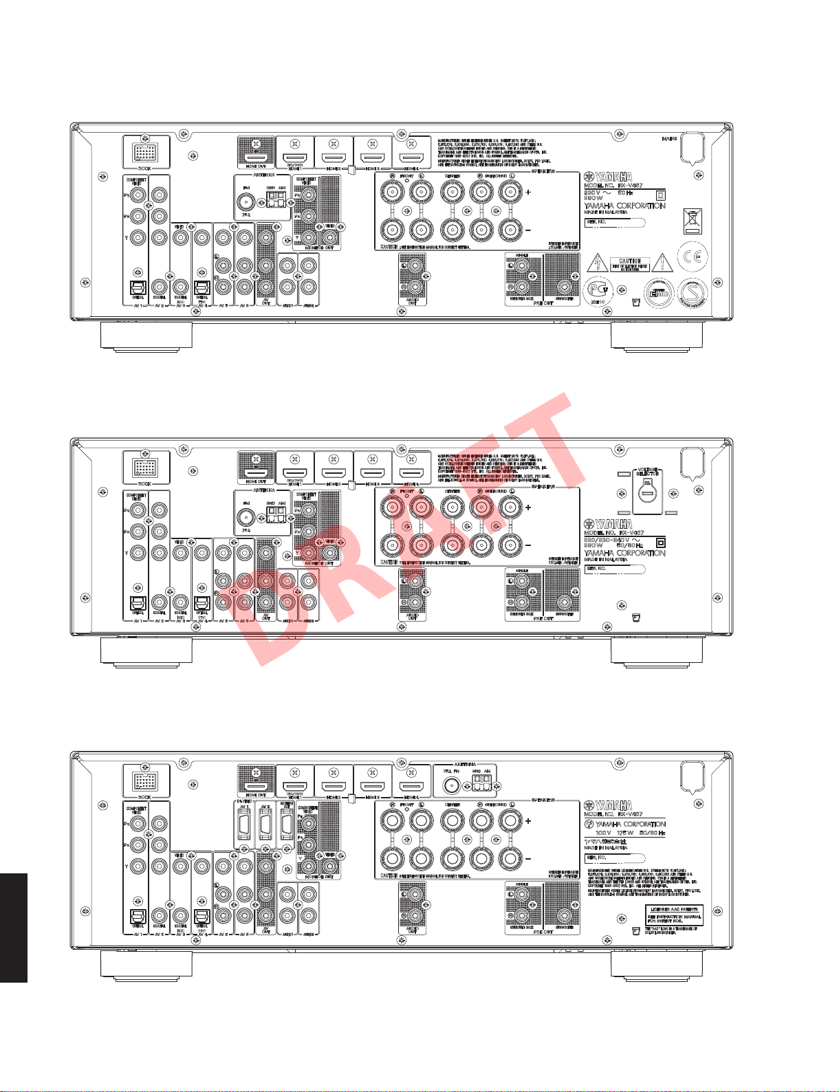
■ REAR PANELS
RX-V467 (U model)
RX-V467 (C model)
RX-V467 (R model)
RX-V467/HTR-4063
4
RX-V467 (T model)
DRAFT
RX-V467 (K model)
RX-V467/HTR-4063
RX-V467 (A model)
RX-V467/HTR-4063
5
RX-V467/HTR-4063
DRAFT
RX-V467 (B, G, F models)
RX-V467 (L model)
RX-V467 (J model)
RX-V467/HTR-4063
6
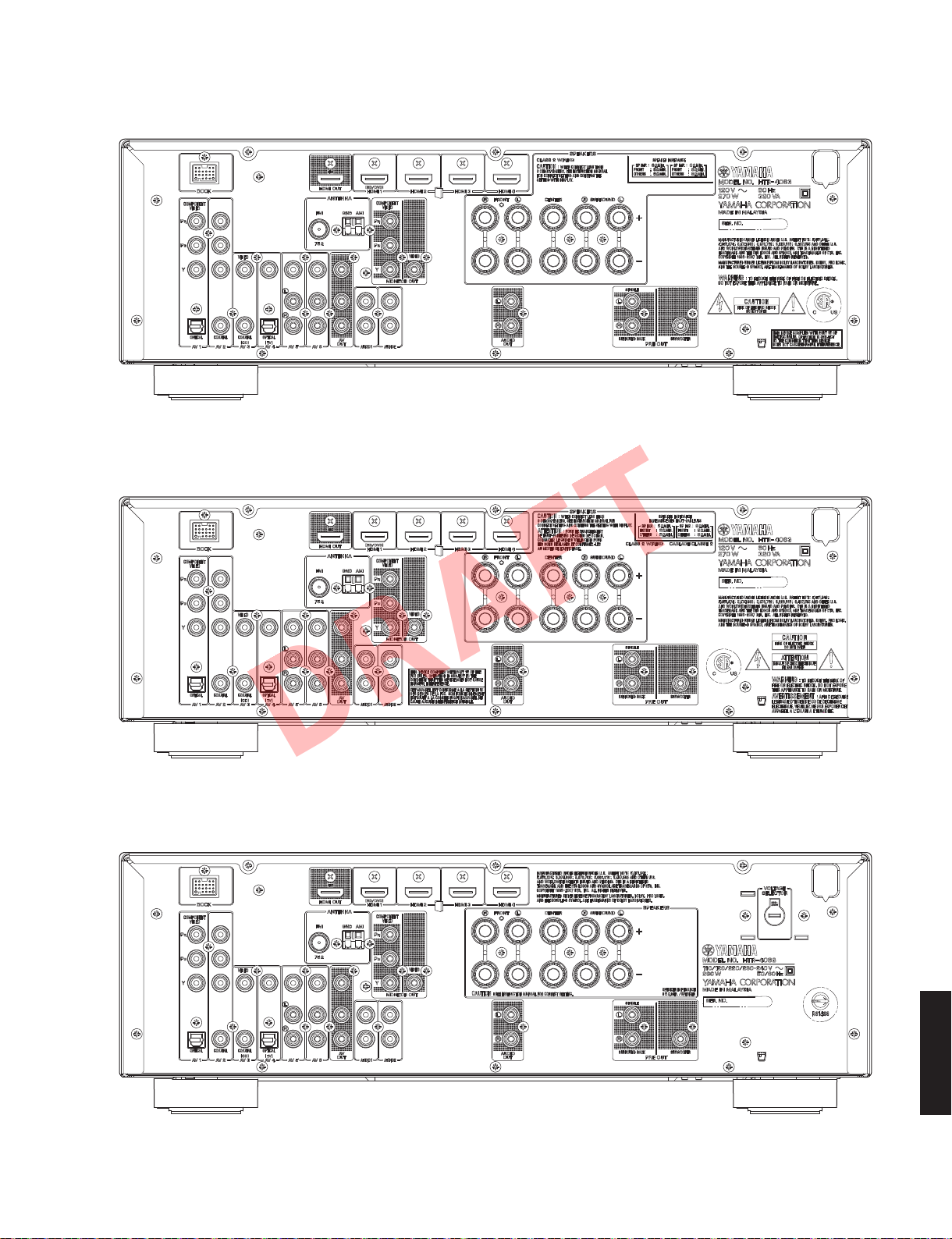
HTR-4063 (U model)
DRAFT
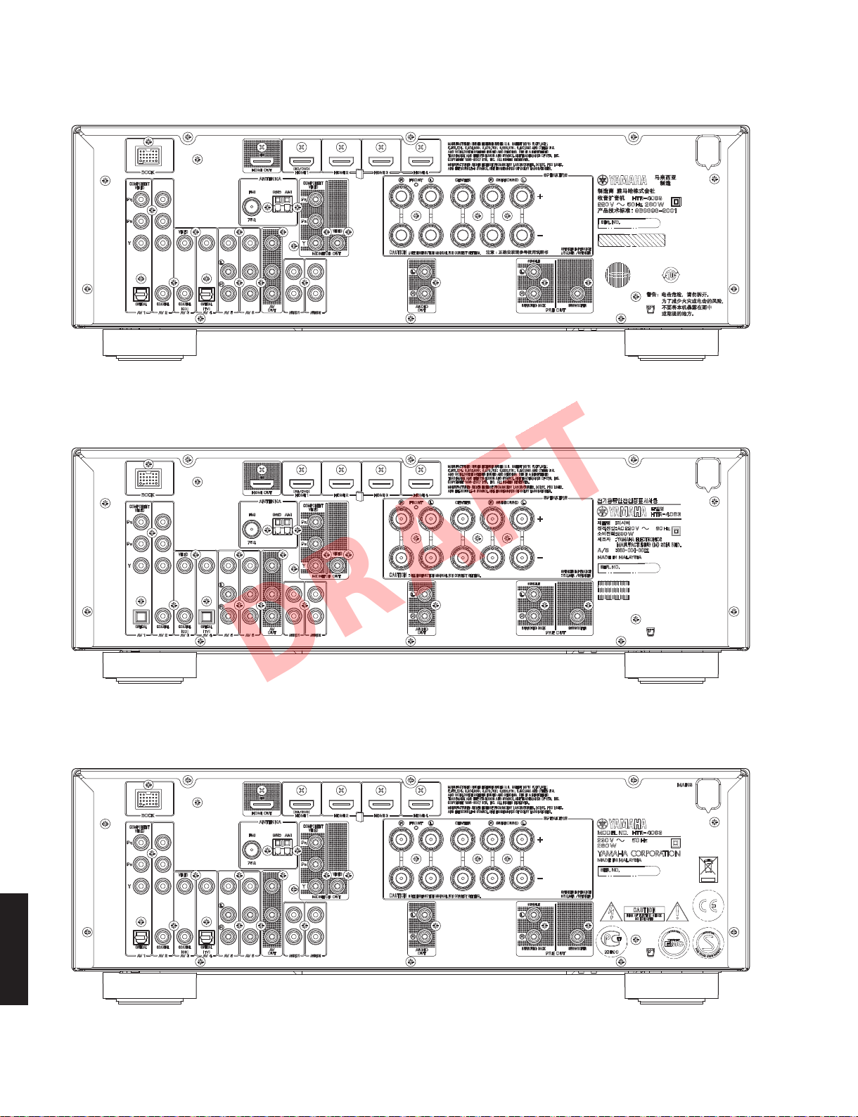
HTR-4063 (C model)
RX-V467/HTR-4063
HTR-4063 (R model)
RX-V467/HTR-4063
7
RX-V467/HTR-4063
DRAFT
HTR-4063 (T model)
HTR-4063 (K model)
HTR-4063 (G, F models)
RX-V467/HTR-4063
8

HTR-4063 (L model)
DRAFT
RX-V467/HTR-4063
■ REMOTE CONTROL PANEL
RAV334
RCU sheet (T model)
RX-V467/HTR-4063
9

RX-V467/HTR-4063
DRAFT
■ SPECIFICATIONS /
■ Audio Section /
Minimum RMS Output Power (Power Amp. Section) /
定格出力(パワーアンプ部)
(1 kHz, 0.9 % THD)
U, C models (8 ohms)
FRONT L/R ...................................................................... 105 W/ch
CENTER ............................................................................... 105 W
SURROUND L/R .............................................................. 105 W/ch
R, T, K, A, B, G, F, L, J models (6 ohms)
FRONT L/R ...................................................................... 105 W/ch
CENTER ............................................................................... 105 W
SURROUND L/R .............................................................. 105 W/ch
Maximum Power /
[R, T, K, L, J models]
FRONT L/R ...................................................................... 140 W/ch
CENTER ............................................................................... 140 W
SURROUND L/R .............................................................. 140 W/ch
MAX. Power Per Channel (1 kHz, 0.7 % THD, 4 ohms)
[B, G, F, L models]
FRONT L/R ...................................................................... 120 W/ch
CENTER ............................................................................... 120 W
SURROUND L/R .............................................................. 120 W/ch
IEC Power (1 kHz, 0.9 % THD, 8 ohms) [B, G, F, L models]
FRONT L/R ........................................................................105 W/ch
Dynamic Power Per Channel /
FRONT L/R drive
U, C models
(8 / 6 / 4 / 2 ohms) ................................... 110 / 130 / 160/ 180 W
R, T, K, A, B, G, F, L, J models
(6 / 4 / 2 ohms) ................................................. 110 / 130/ 150 W
Dynamic Headroom [U, C models]
8 ohms ...................................................................................0.2 dB
Input Sensitivity/Input Impedance /
(1 kHz, 100 W/6 ohms)
AV5 etc. ............................................................200 mV / 47 k-ohms
Maximum Input Signal /
AV5 etc. .......................................................................2.3 V or more
Output Level/Output Impedance /
REC OUT .........................................................200 mV / 1.2 k-ohms
PRE OUT ................................................................. 1 V / 1.2 k-ohms
SUBWOOFER (2 ch stereo and FRONT SP: small)
.............................................................................. 1 V / 1.2 k-ohms
Headphone Jack Rated Output/Output Impedance /
ヘッドホン出力/出力インピーダンス
AV5 etc. input (1 kHz, 50 mV, 8 ohms) .............. 100 mV / 470 ohms
Frequency Response /
AV5 etc., FRONT (10 Hz to 100 kHz) ...................................0 / -3 dB
Total Harmonic Distortion /
AV5 etc. (DIRECT) to FRONT SP OUT (1 kHz, 50 W)
U, C models (8 ohms) ..............................................0.06 % or less
R, T, K, A, B, G, F, L, J models (6 ohms) ..................0.06 % or less
Signal to Noise Ratio /
AV5, etc. (DIRECT) to SP OUT (Input shorted 250 mV)
.............................................................................. 100 dB or more
Residual Noise /
FRONT L/R to SP OUT ................................................150 μV or less
Channel Separation /
AV5, etc. (Input 5.1 k-ohms shorted)
1 kHz / 10 kHz ............................... 60 dB or more / 45 dB or more
RX-V467/HTR-4063
Volume Control /
......................................... MUTE / -80 dB to +16.5 dB / 0.5 dB step
オーディオ部
実用最大出力
残留ノイズ
チャンネルセパレーション
可変範囲/ステップ
(JEITA) (1 kHz, 10 % THD, 6 ohms)
ダイナミックパワー
最大許容入力
出力電圧/出力インピーダンス
再生周波数帯域
全高調波歪率
信号対雑音比
(IHF-A Network)
参考仕様
(IHF)
入力感度/入力インピーダンス
(1 kHz, 0.5 % THD)
(IHF-A network)
Tone Control Characteristics /
FRONT L/R
Bass
Boost/Cut ........................................... ±10 dB / 2 dB, step 50 Hz
Turnover frequency ..........................................................350 Hz
Treble
Boost/Cut ..........................................±10 dB / 2 dB, step 20 kHz
Turnover frequency .........................................................3.5 kHz
Filter Characteristics /
FRONT, CENTER, SURROUND, SURROUND BACK small (H.P.F.)
....................fc=40/60/80/90/100/110/120/160/200 Hz, 12 dB/oct.
SUBWOOFER small (L.P.F.)
....................fc=40/60/80/90/100/110/120/160/200 Hz, 24 dB/oct.
■ Video Section /
Video Signal Type /
U, C, R, K, J models ..............................................................NTSC
T, A, B, G, F, L models ..............................................................PAL
Video conversion /
.......................................................................................NTSC/PAL
Composite Video Signal Level /
...............................................................................1 Vp-p / 75 ohms
Component Video Signal Level /
Y .............................................................................1 Vp-p / 75 ohms
Cb/Cr ..................................................................0.7 Vp-p / 75 ohms
D4 Video Signal /
Y .............................................................................1 Vp-p / 75 ohms
Cb/Cr ..................................................................0.7 Vp-p / 75 ohms
Video Maximum Input Level /
(VIDEO COMV. OFF
............................................................................... 1.5 Vp-p or more
Video Signal to Noise Ratio /
................................................................................... 50 dB or more
Monitor Out Frequency Response /
Component video signal level .......................5 Hz to 60 MHz, -3 dB
D4 video signal /
■ FM Section /
Tuning Range /
U, C models ......................................................... 87.5 to 107.9 MHz
R, L models ......................87.5 to 108.0 MHz / 87.50 to 108.00 MHz
T, K, A, B, G, F models ....................................87.50 to 108.00 MHz
J model ..................................................................76.0 to 90.0 MHz
50 dB Quieting Sensitivity /
(1 kHz, 100 % MOD.)
MONO/STEREO ........................................................ 3 μV (20.8 dBf)
Signal to Noise Ratio /
Mono ........................................................................................74 dB
Stereo ......................................................................................69 dB
Harmonic Distortion / 歪率 (1 kHz)
Mono ........................................................................................ 0.3 %
Stereo ......................................................................................0.3 %
Antenna Input /
....................................................................... 75 ohms unbalanced
ビデオ部
ビデオ信号方式
ビデオコンバージョン
D4 ビデオ信号
)
D4 ビデオ信号
FM部
受信周波数範囲
アンテナ入力
トーンコントロール特性
フィルタ特性
S/N 比
コンポジットビデオ信号
コンポーネントビデオ信号
[J model]
ビデオ最大許容入力
ビデオ信号対雑音比
モニター出力周波数帯域
(J model) ....5 Hz to 60 MHz, -3 dB
50dBSN 感度
(IHF)
(IHF)
10
RX-V467/HTR-4063
DRAFT
■ AM Section /
Tuning Range
U, C models ........................................................... 530 to 1,710 kHz
R, L models ..............................530 to 1,710 kHz / 531 to 1,611 kHz
T, K, A, B, G, F, J models .......................................531 to 1,611 kHz
Antenna /
■ General /
Power Supply /
U, C models ............................................................ AC 120 V, 60 Hz
R model ................................ AC 110/120/220/230–240 V, 50/60 Hz
T model ................................................................... AC 220 V, 50 Hz
K model .................................................................. AC 220 V, 60 Hz
A model .................................................................. AC 240 V, 50 Hz
B, G, F models ........................................................ AC 230 V, 50 Hz
L model ............................................... AC 220/230–240 V, 50/60 Hz
J model .............................................................. AC 100 V, 50/60 Hz
Power Consumption /
U, C models ..............................................................270 W / 320 VA
R, T, K, A, B, G, F, L models ....................................................280 W
J model ...................................................................................175 W
Standby Power Consumption (reference data)
HDMI control: OFF / Standby through: OFF .................0.2 W or less
HDMI control: ON / Standby through: ON / Repeat ......3.0 W or less
HDMI control: ON / Standby through: ON ....................1.2 W or less
Maximum Power Consumption
................................................................................................ 440 W
Dimensions (W x H x D) /
..................................... 435 x 151 x 364 mm (17-1/8" x 6" x 14-3/8")
Weight / 質量
............................................................................... 8.4 kg (18.5 lbs.)
Finish /
[RX-V467]
R, T models .....................................................................Gold color
U, C, R, T, K, A, B, G, F, L, J models ............................ Black color
G, F, L models ........................................................... Titanium color
R, K, G, F, L models ......................................................Silver color
[HTR-4063]
T model ...........................................................................Gold color
U, C, R, T, K, G, F, L models ........................................ Black color
R, K, G models ..............................................................Silver color
Accessories /
Remote control ..............................................................................x 1
Battery (R03, AAA, UM-4) .............................................................x 2
Indoor FM antenna (1.4 m) ...........................................................x 1
AM loop antenna (1.0 m) ..............................................................x 1
YPAO microphone (6.0 m) .............................................................x 1
Video AUX input cover ..................................................................x 1
RCU sheet (T model) .....................................................................x 1
アンテナ
総合
仕上げ
AM部
....................................................... Loop antenna
電源電圧
消費電力
寸法(幅 × 高さ × 奥行き)
付属品
Manufactured under license from Dolby Laboratories. Dolby, Pro Logic and
the double-D symbol are trademarks of Dolby Laboratories.
ドルビーラボラトリーズからの実施権に基づき製造されています。「ドルビー」、
「PROLOGIC」、「SurroundEX」およびダブル D 記号
ズの商標です。
DTS is a registered trademark and the DTS logos, Symbol, DTS-HD and
DTS-HD Master Audio are trademark of DTS, Inc.
DTS は DTS 社の登録商標です。また、DTS ロゴ、記号、および DTS-HD、DTSHDMasterAudio は DTS 社の商標です。
著作権 1996-2007 年 DTS 社。不許複製。
“iPod” is a trademark of Apple Inc., registered in the U.S. and other
countries. “iPhone” is a trademark of Apple Inc.
iPod は、米国および他の国々で登録された AppleInc. の商標または登録商標で
す。
iPhone は、AppleInc. の商標または登録商標です。
Bluetooth is a registered trademark of the Bluetooth SIG and is used by
Yamaha in accordance with a license agreement.
Bluetooth は、BluetoothSIG の登録商標でありヤマハはライセンスに基づき使
用しています。
“HDMI”, the “HDMI” logo and “High-Definition Multimedia Interface” are
trademarks, or registered trademarks of HDMI Licensing LLC.
HDMI、HDMI ロゴ、および High-DefinitionMultimediaInterface は、
HDMILicensing,LLC の商標または登録商標です。
“SILENT CINEMA” is a trademark of Yamaha Corporation.
「サイレントシネマ™ SILENTCINEMA ™」はヤマハ株式会社の登録商標です。
AAC ロゴマーク はドルビーラボラトリーズの商標です。
、ドルビーラボラトリー
RX-V467/HTR-4063
* Specifications are subject to change without notice.
※ 参考仕様および外観は、製品の改良のため予告なく変更すること
があります。
U .......................U.S.A. model
C .................Canadian model
R ....................General model
T .................... Chinese model
K .....................Korean model
A ................Australian model
B ......................British model
G .................European model
F .................... Russian model
L .................Singapore model
J .................. Japanese model
11
RX-V467/HTR-4063
DRAFT
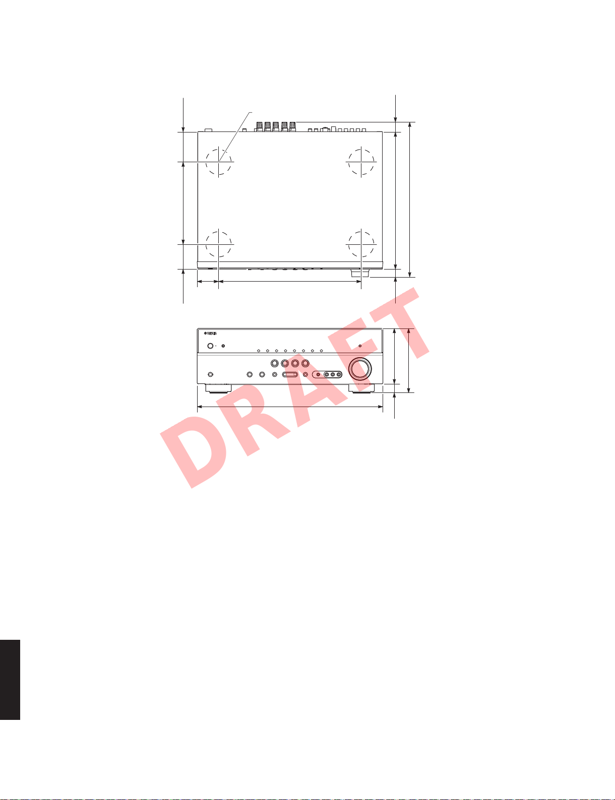
• DIMENSIONS
Top view
72
(2-7/8")
193 (7-5/8")
ø 60
23
(7/8")
364 (14-3/8")
323 (12-3/4")
58
(2-1/4")
(2")
Front view
335 (13-1/4")50
435 (17-1/8")
18
130 (5-1/8")21
(3/4")
151 (6")
(7/8")
Unit: mm (inch)
単位
:mm(インチ)
RX-V467/HTR-4063
12
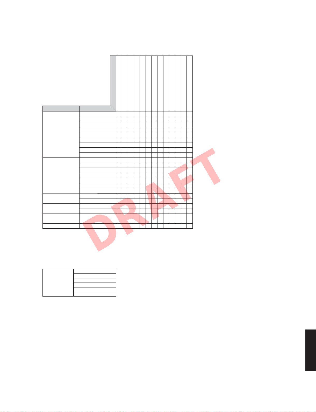
• SELECT MENU
DRAFT
Sound field parameters
RX-V467/HTR-4063
Parameter
Category Program
MOVIE Standard
MUSIC Hall in Munich
STEREO 2ch Stereo
MUSIC ENHANCER Straight Enhancer
SUR. DECODE Surround Decoder
STRAIGHT
: Setting is possible only when Pro Logic II x Music (Pro Logic II Music) is selected using decode type.
△
DecodeType で ProLogicIIxMusic(ProLogicIIMusic)を選択時のみ設定可
: Setting is possible only when Neo:6 Music is selected using decode type.
■
DecodeType で Neo:6Music を選択時のみ設定可
Spectacle
Sci-Fi
Adventure
Drama
Mono Movie
Sports
Action Game
Roleplaying Game
Hall in Vienna
Chamber
Cellar Club
The Roxy Theatre
The Bottom Line
Music Video
7ch Stereo
7ch Enhancer
Decode Type
DSP Level: -6dB to +3dB
Center Level: 0 to 100%
Surround L Level: 0 to 100%
Surround R Level: 0 to 100%
Surround Back Level: 0 to 100%
Direct: Auto/Off
Effect Level: High/Low
Panorama: On/Off
Center Width: 0 to 7
●●
●●
●●
●●
●●
●●
●●
●●
●●
●●
●●
●●
●●
●●
●●
●●
●●●● ●
●
*1
●●
●●
●●
△△△■●
Dimension: -3 to STD to +3
C. Image: 0.0 to 1.0
Initialize
*1 Decode Type
Decode Type
Pro Logic
PL II x Movie / PL II Movie
PL II x Music / PL II Music
PL II x Game / PL II Game
Neo:6 Cinema
Neo:6 Music
PL II when Surround Back is None /
PL II when Surround Back is None /
PL II when Surround Back is None /
SurroundBack が None の場合は PLII
SurroundBack が None の場合は PLII
SurroundBack が None の場合は PLII
RX-V467/HTR-4063
13
RX-V467/HTR-4063
DRAFT
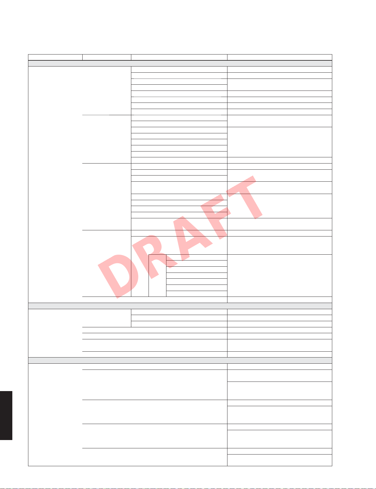
• SET MENU TABLE
MAIN MENU SUB-MENU PARAMETER VALUE [INITIAL VALUE]
1 • Speaker Setup
2 • Sound Setup
3 • HDMI Setup
RX-V467/HTR-4063
1 Config Subwoofer [Yes] / None
2 Level FL (Front speaker L)
3 Distance Unit meters (m) / [feet (ft)]
4 Equalizer EQ Type Select [GEQ] / Off
5 Test Tone [Off] / On
1 Lipsync HDMI Auto [Off] / On
2 Adaptive DRC Auto / [Off]
3 D.Range Min/Auto / STD / [Max]
4 Max Volume -30.0 to +15.0 dB / +16.5 dB (Maximum volume), [+16.5
5 Init. Volume Off, Mute, -80 dB to +16.5 dB [Off], 0.5 dB step
1 Control (HDMI Control) [Off] / On
2 TV Audio AV1 / AV2 / AV3 / [AV4] / AV5 / AV6 /
3 ReturnChan (Audio Return Channel) [Off] / On
4 Standby (Standby Through) [Off] / On
5 Audio [Amp] / TV / Amp+TV
Front speaker Small / [Large]
Center speaker
Surround speaker L/R
Surround back L/R speaker [None] / SMLx1 / SMLx2 / LRGx1 / LRGx2
Crossover 40 / 60 / [80] / 90 / 100 / 110 / 120 / 160 / 200 Hz
Subwoofer Phase [NRM] / REV
Extra Bass On / [Off]
FR (Front speaker R)
C (Center speaker)
SL (Surround speaker L)
SR (Surround speaker R) -10.0 to +10.0 dB, [-1.0 dB], 0.5 dB step
SBL (Surround back speaker L)
SBR (Surround back speaker R)
SWFR (Subwoofer) -10.0 to +10.0 dB, [0 dB], 0.5 dB step
Front L 0.30 to 24.00 m, [3.00 m], 0.1 m step
Front R
Center 0.30 to 24.00 m, [2.60 m], 0.1 m step
Sur. L
Sur. R 0.30 to 24.00 m, [2.40 m], 0.1 m step
Sur. B L 1.0 to 80.0 ft, [8.0 ft], 0.5 ft step
Sur. B R
SWFR 0.30 to 24.00 m, [3.00 m], 0.1 m step
GEQ * “GEQ” is available only when “EQ Type Select” is set
Front L 63 Hz ···········||··········· 0 dB
Front R 160 Hz ···········||··········· 0 dB
Center 400 Hz ···········||··········· 0 dB
Sur. L 1 kHz ···········||··········· 0 dB
Sur. R 2.5 kHz ···········||··········· 0 dB
SBL 6.3 kHz ···········||··········· 0 dB
SBR 16 kHz ···········||··········· 0 dB
Auto 0 to 240 ms, 1 ms step
Manual 0 to 240 ms, [0 ms], 1 ms step
None / [Small] / Large
-10.0 to +10.0 dB, [0 dB], 0.5 dB step
1.0 to 80.0 ft, [10.0 ft], 0.5 ft step
1.0 to 80.0 ft, [8.5 ft], 0.5 ft step
1.0 to 80.0 ft, [10.0 ft], 0.5 ft step
to “GEQ”.
“EQTypeSelect” にて “GEQ” 選択時のみ設定可能
-6.0 to +6.0 dB, [0 dB], 0.5 dB step
dB], 5.0 dB step
AUDIO1 / AUDIO2
* “TV Audio” is available only when “Control” is set to
“On”.
“Control” にて “On” 選択時のみ設定可能
* “ReturnChan” is available only when “Control” is set
to “On”.
“Control” にて “On” 選択時のみ設定可能
* “Standby” is available only when “Control” is set to
“Off”.
“Control” にて “Off” 選択時のみ設定可能
* “Audio” is available only when “Control” is set to “Off”.
“Control” にて “Off” 選択時のみ設定可能
14
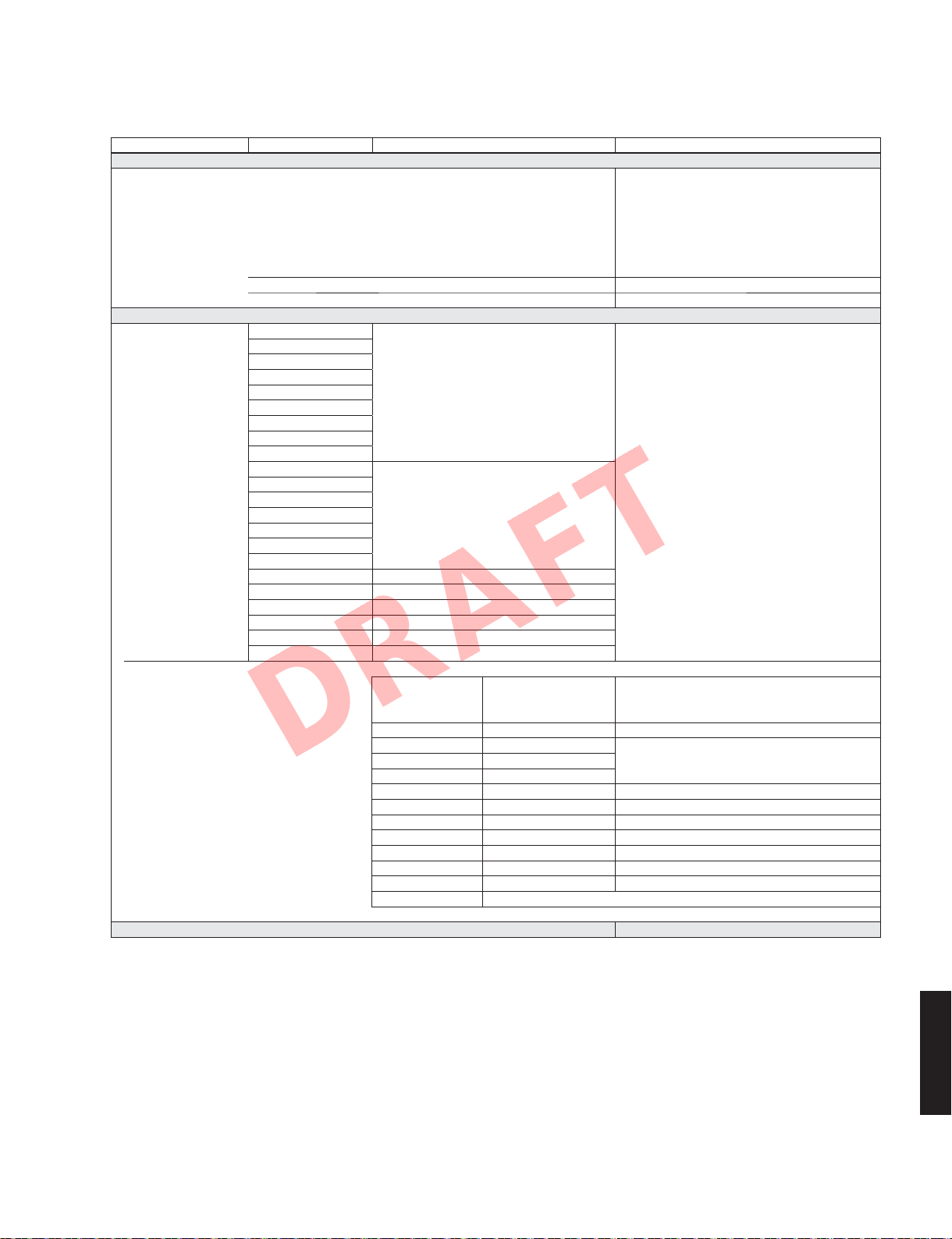
MAIN MENU SUB-MENU PARAMETER VALUE [INITIAL VALUE]
DRAFT
4 • Function Setup
5 DSP Parameter
STEREO 2ch Stereo [7], [13]
MUSIC ENHANCER Straight Enhancer [8], [13]
SUR. DECODE Sur. Decoder [1], [9], [10], [11], [12], [13]
STRAIGHT
1 Input Rename Input is possible to 9 characters
Input possible Character type
Capital : A to Z
Small : a to z
Figure : 0 to 9
Symbols : # * + , - etc.
2 Auto Power Down [Off] / 4 hours / 8 hours / 12 hours
3 Dimmer -4 to 0, [0]
MOVIE Standard
Spectacle
Sci-Fi
Adventure
Drama
Mono Movie
Sports
Action Game
Roleplaying Game
MUSIC Hall in Munich
Hall in Vienna
Chamber
Cellar Club
The Roxy Theatre
The Bottom Line
Music Video
7ch Stereo [3], [4], [5], [6], [13]
7ch Enhancer [8], [13]
[2], [13]
[2], [13]
Space
RX-V467/HTR-4063
[1] Decode Type Pro Logic, PL II x Movie / PL II Movie,
PL II x Music / PL II Music, PL II x Game / PL II Game,
Neo:6 Cinema, Neo:6 Music
[2] DSP Level -6 to +3 dB, [0 dB]
[3] Center Level
[4] Surround L Level 0 to 100 %, [100 %]
[5] Surround R Level
[6] Surround Back Level 0 to 100 %, [35 % (7.1 ch) / 50 % (6.1 ch)]
[7] Direct [Auto] / Off
[8] Effect Level [High] / Low
[9] Panorama [Off] / On
[10] Center Width 0 to 7, [3]
[11] Dimension -3 to STD to +3, [STD (Standard)]
[12] C. Image 0.0 to 1.0, [0.3]
[13] Initialize
6 Memory Guard [Off] / On
RX-V467/HTR-4063
15
RX-V467/HTR-4063
DRAFT
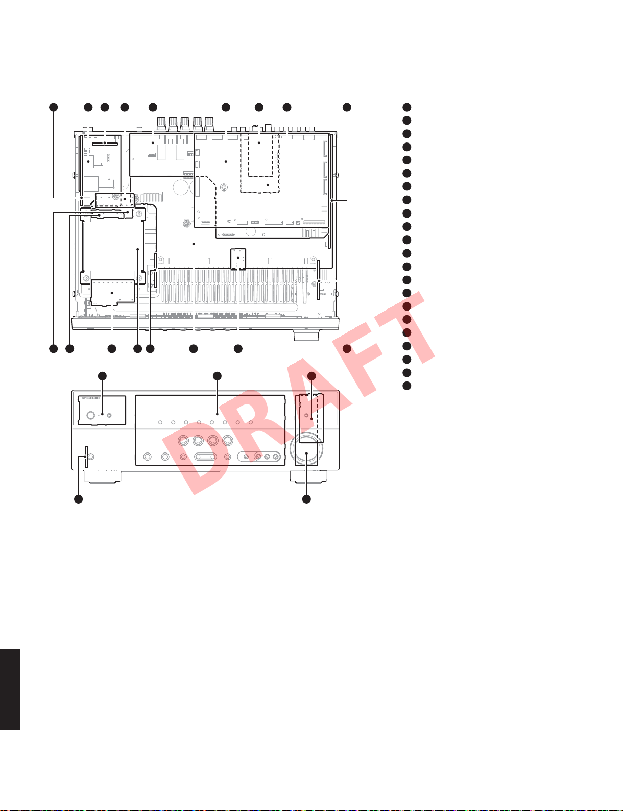
■ INTERNAL VIEW
2
1617 1112152114 10
4635 7 91 8
13
18 19 20
1
VIDEO (2) P.C.B.
2
VIDEO (3) P.C.B.
3
MAIN (3) P.C.B. (R, L models)
4
MAIN (2) P.C.B.
5
VIDEO (1) P.C.B.
6
DIGITAL P.C.B.
7
TUNER
8
VIDEO (8) P.C.B. (J model)
9
OPERATION (2) P.C.B.
10
OPERATION (6) P.C.B.
11
MAIN (5) P.C.B.
12
MAIN (1) P.C.B.
13
MAIN (6) P.C.B.
14
POWER TRANSFORMER
15
VIDEO (6) P.C.B.
16
VIDEO (7) P.C.B.
17
MAIN (4) P.C.B. (R, L models)
18
OPERATION (4) P.C.B.
19
OPERATION (1) P.C.B.
20
OPERATION (8) P.C.B.
21
OPERATION (5) P.C.B.
22
OPERATION (3) P.C.B.
22
■ SERVICE PRECAUTIONS /
サービス時の注意事項
Safety measures
• Some internal parts in this product contain high voltages
and are dangerous.
Be sure to take safety measures during servicing,
such as wearing insulating gloves.
• Note that positions indicated below are dangerous
even after the power is turned off because an electric
charge remains and a high voltage continues to exist
there.
Before starting any repair work, perform discharge
by connecting a discharge resistor (5k-ohms/10W)
between terminals at following positions.
RX-V467/HTR-4063
16
The time required for discharging is about 30 seconds.
C3703 on VIDEO (2) P.C.B.
Refer to “PRINTED CIRCUIT BOARDS: VIDEO (2)
P.C.B.”.
安全対策
・ この製品の内部には高電圧部分があり危険です。修理
の際は、絶縁性の手袋を使用するなどの安全対策を
行ってください。
・ 下記箇所には電源を OFF にした後も電荷が残り、高電
圧が維持されており危険です。
修理作業前に放電用抵抗(5k Ω /10W)を下記箇所の
端子間に接続して放電してください。
放電所用時間は約 30 秒間です。
VIDEO(2)P.C.B. の C3703
“PRINTEDCIRCUITBOARDS:VIDEO(2) P.C.B.” を参照
してください。
RX-V467/HTR-4063
DRAFT
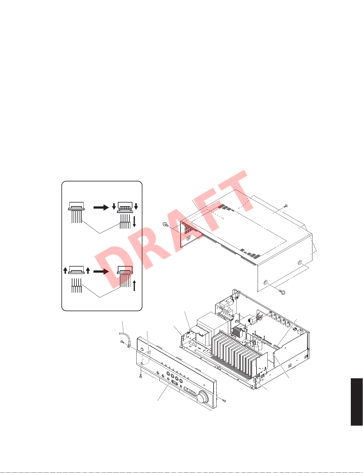
■ DISASSEMBLY PROCEDURES /
(Remove parts in the order as numbered.)
Disconnect the power cable from the AC outlet.
1. Removal of Top Cover
a. Remove 4 screws (①) and 5 screws (②). (Fig. 1)
b. Slide the top cover rearward to remove it. (Fig. 1)
2. Removal of Front Panel Unit
a. Remove 7 screws (③), and remove W4401. (Fig. 1)
b. Remove CB20, CB461 and CB472. (Fig. 1)
c. Unlock and remove CB333. (Fig. 1)
d. Release 2 hooks on both ends and remove the front
panel unit. (Fig. 1)
Remove CB333
Unlocked
ロック解除
Top cover
トップ カ バ ー
分解手順
(番号順に部品を取り外してください。)
AC 電源コンセントから、電源コードを抜いてください。
1. トップカバーの外し方
a. ①のネジ 4 本、②のネジ 5 本を外します。(Fig.1)
b. トップカバーを後方へスライドさせ、取り外します。
(Fig.1)
2. フロントパネルユニットの外し方
a. ③のネジ 7 本を外し、W4401 を取り外します。(Fig.1)
b. CB20、CB461、CB472 を外します。(Fig.1)
c. ロックを外し、CB333 を外します。(Fig.1)
d. フック 2 箇所を外し、フロントパネルユニットを取り
外します。(Fig.1)
②
Connect CB333
Locked
ロック
Cable
ケーブル
Cable
ケーブル
Connected
接続
W4401
CB472
③
③
Front panel unit
フロントパネルユニット
①
Hook
フック
CB333
①
CB20
CB461
Hook
③
フック
RX-V467/HTR-4063
Fig. 1
17
RX-V467/HTR-4063
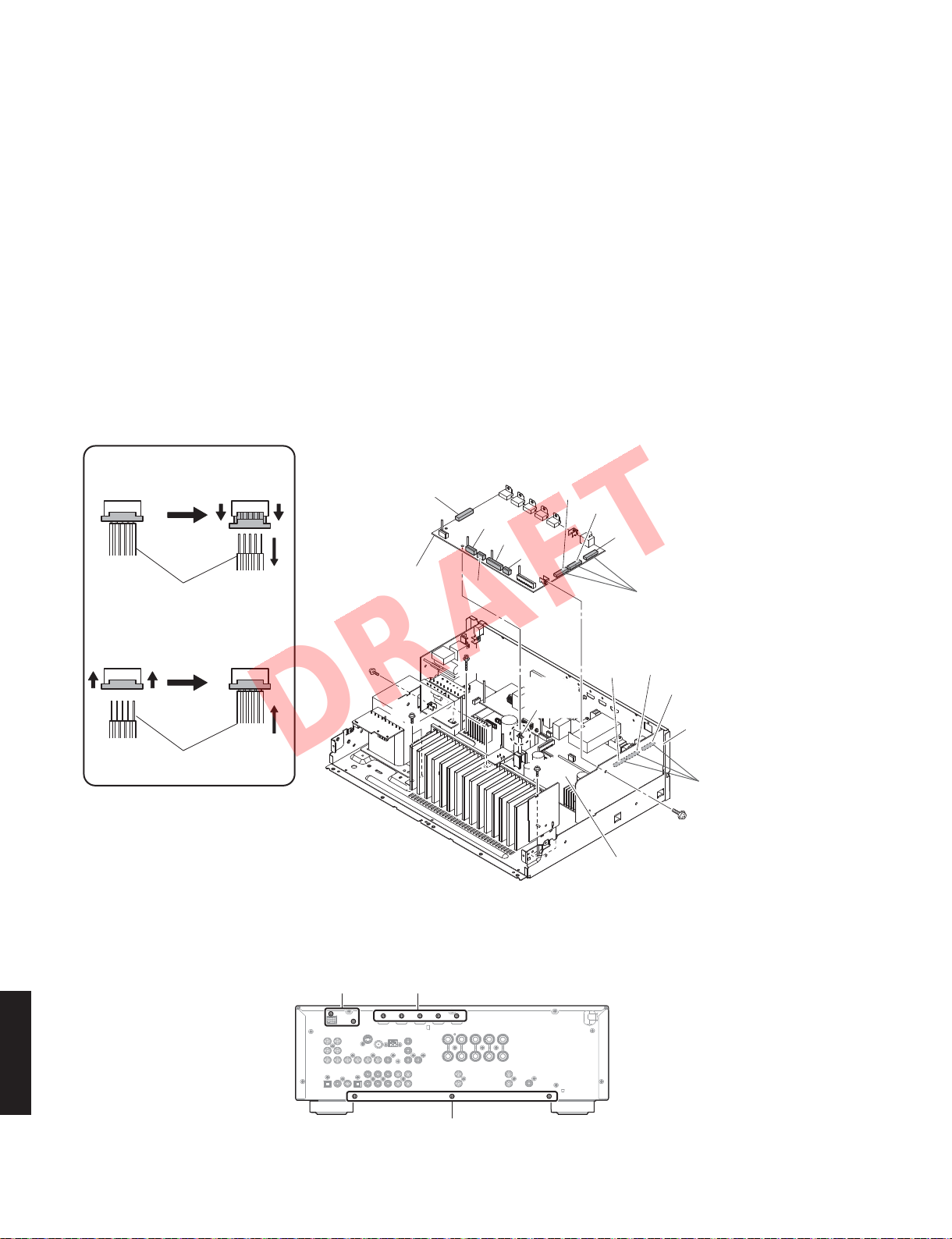
DRAFT
3. Removal of DIGITAL P.C.B.
a. Remove 2 screws (④) and 5 screws (⑤). (Fig. 3)
b. Remove screw (⑥). (Fig. 2)
c. Remove CB7 and CB25, CB72 and CB73 (B, G, F
models). (Fig. 2)
d. Unlock and remove CB22–24. (Fig. 2)
e. Release hook. (Fig. 2)
f. Remove the DIGITAL P.C.B. which is connected directly
to the OPERATION (2) P.C.B. with board-to-board
connectors. (Fig. 2)
4. Removal of AMP Unit
a. Remove 3 screws (⑦) and 4 screws (⑧). (Fig. 2)
b. Remove 3 screws (⑨). (Fig. 3)
c. Remove the amp unit. (Fig. 2)
Remove CB22–CB24
Cable
ケーブル
Connect CB22–CB24
Locked
ロック
Unlocked
ロック解除
Connected
接続
DIGITAL P.C.B.
⑧
CB25
⑧
3. DIGITALP.C.B. の外し方
a. ④のネジ 2 本、⑤のネジ 5 本を外します。(Fig.3)
b. ⑥のネジ 1 本を外します。(Fig.2)
c. CB7、CB25、CB72 を外します。(Fig.2)
d. ロックを外し、CB22 〜 24 を外します。(Fig.2)
e. フック 1 箇所を外します。(Fig.2)
f. DIGITALP.C.B.を取り外します。ただし、DIGITALP.C.B.
は OPERATION(2)P.C.B. に基板対基板コネクターで
直接接続されています。(Fig.2)
4. アンプユニットの外し方
a. ⑦のネジ 3 本、⑧のネジ 4 本を外します。(Fig.2)
b. ⑨のネジ 3 本を外します。(Fig.3)
c. アンプユニットを取り外します。(Fig.2)
CB63
CB62
CB24
CB23
CB22
CB7
⑦
Hook
フック
CB61
Board-to-board connectors
基板対基板コネクター
CB458
CB455
CB452
OPERATION (2) P.C.B.
Cable
ケーブル
Fig. 2
④⑤
RX-V467/HTR-4063
⑨
Fig. 3
18
⑧
Rear view
Board-to-board
connectors
基板対基板コネクター
⑥
AMP unit
アンプユニット
RX-V467/HTR-4063
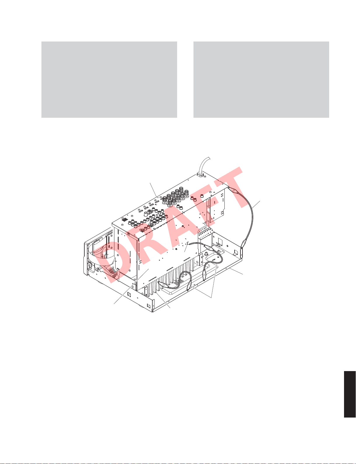
DRAFT
When checking the P.C.B.s:
• Place the P.C.B.s (with rear panel) upright. (Fig. 4)
• Connect the ground points of the heatsink, rear
panel and MAIN (1) P.C.B. (G1000) to the chassis
with a ground lead or the like. (Fig. 4)
• When connecting the flexible flat cable, be careful
with polarity.
• Reconnect all cables (connectors) that have been
disconnected.
Rear panel
リアパ ネ ル
P.C.B. をチェックする場合には:
・ リアパネルと一緒に P.C.B. を立ち上げて置きます。
(Fig.4)
・ ヒートシンク、リアパネル、MAIN(1)P.C.B. の
G1000 のアースをリード線等でシャーシに接続して
ください。(Fig.4)
・ フラットケーブルを接続する際、極性に注意してく
ださい。
・ 外したケーブル(コネクター)をすべて接続します。
Ground lead
アース線
MAIN (1) P.C.B.
G1000
Heatsink
ヒートシンク
Fig. 4
Chassis
シャーシ
Ground lead
アース線
RX-V467/HTR-4063
19

RX-V467/HTR-4063
DRAFT
■ UPDATING FIRMWARE /
When the following parts are replaced, the firmware must
be updated to the latest version by using the corresponding
update method.
Replaced parts
DIGITAL P.C.B. yes yes
IC20 (Main microprocessor) of DIGITAL P.C.B. no yes
IC49 (TI (DSP) flash ROM) of DIGITAL P.C.B. yes yes
● Confirmation of firmware version and checksum
Before and after updating the firmware, check the
firmware version and checksum by using the selfdiagnostic function menu.
Start up the self-diagnostic function and select “25.
ROM VER/SUM/PORT” menu.
Using the sub-menu, have the firmware version and
checksum displayed, and note them down.
(See “SELF-DIAGNOSTIC FUNCTION”)
ファームウェアの書き込み
下記の部品を交換した場合、それに対応する方法でファー
ムウェアを最新バージョンにアップデートする必要があ
ります。
Writing method using the CD /
CD を使用して書き込む方法
● ファームウェアのバージョンとチェックサムの
確認
ファームウェアのアップデートの前後に、ファーム
ウェアのバージョンとチェックサムをダイアグで確
認します。
ダイアグを起動し、“25.ROM VER/SUM/PORT” を選
択します。
サブメニューでファームウェアのバージョンと
チェックサムを表示し、それらを書きとめます。
(「ダイアグ」参照)
Writing method using PC (RS-232C) /
PC(RS-232C)を使用して書き込む方法
* When the firmware version is different from written
one after updating, perform the updating procedure
again from the beginning.
● Initializing the back-up IC
(EEPROM: IC22 of the DIGITAL P.C.B.)
After updating the firmware, the back-up IC MUST be
initialized by the following procedure to have proper
memorization of the set up information (soundfield
parameters, system memory and tuner presetting,
etc.).
Start up the self-diagnostic function and select “24.
FACTORY PRESET” menu. (See “SELF-DIAGNOSTIC
FUNCTION”)
Select “24. PRESET RSRV”, press the “
of this unit to turn off the power once and turn on the
power again. Then the back-up IC is initialized.
” (Power) key
※ アップデート後、ファームウェアのバージョンが
書き込まれたものと異なる場合、アップデートの
操作を最初からやり直してください。
● バックアップ IC の初期化
(EEPROM:DIGITALP.C.B. の IC22)
ファームウェアのアップデート後、設定情報(音
場プログラムのパラメーターやシステムメモリー、
チューナープリセット等)を正常に記憶するために、
下記の方法でバックアップ IC を初期化する必要があ
ります。
本機のダイアグを起動し、“24.FACTORYPRESET” を
選択します。(「ダイアグ」参照)
“24.PRESETRSRV” を選択し、“
して電源を一度切ってから、もう一度電源を入れる
とバックアップ IC が初期化されます。
” ( パワー)キーを押
RX-V467/HTR-4063
20

RX-V467/HTR-4063
DRAFT
CD を使用して書き込む方法WritingmethodusingtheCD
● Required Tools
• DVD or CD player (with DIGITAL OUTPUT (OPTICAL
or COAXIAL) jack)
• Optical cable (when OPTICAL jack is used)
• Digital audio pin cable (when COAXIAL jack is
used)
• Firmware CD
Download the latest firmware from the specified
*
download source and create the firmware CD.
● 必要なツール
・ DVD または CDプレーヤー(DIGITALOUTPUT
(OPTICAL)端子付き)
・ 光ファイバーケーブル(OPTICAL 端子使用時)
・ デジタル音声ピンケーブル(COAXIAL 端子使用時)
・ ファームウェア CD
※ 指定のダウンロード先から、最新のファーム
ウェアをダウンロードしてファームウェア CD
を製作してください。
RX-V467/HTR-4063
21

RX-V467/HTR-4063
DRAFT
● Connection
Connect this unit and DVD/CD player as shown
below. (Fig. 1)
Example of OPTICAL jack /
This unit / 本機
OPTICAL 端子使用例
Optical cable
光ファイバ ー ケ ー ブ ル
● 接続
本機と DVD/CD プレーヤーを下記のように接続しま
す。(Fig.1)
DVD/CD player / DVD/CDプレーヤー
Example of COAXIAL jack /
This unit / 本機
COAXIAL 端子使用例
DVD/CD player / DVD/CDプレーヤー
Digital audio pin cable
デジタル 音声ピンケーブル
Fig. 1
RX-V467/HTR-4063
22
RX-V467/HTR-4063
DRAFT
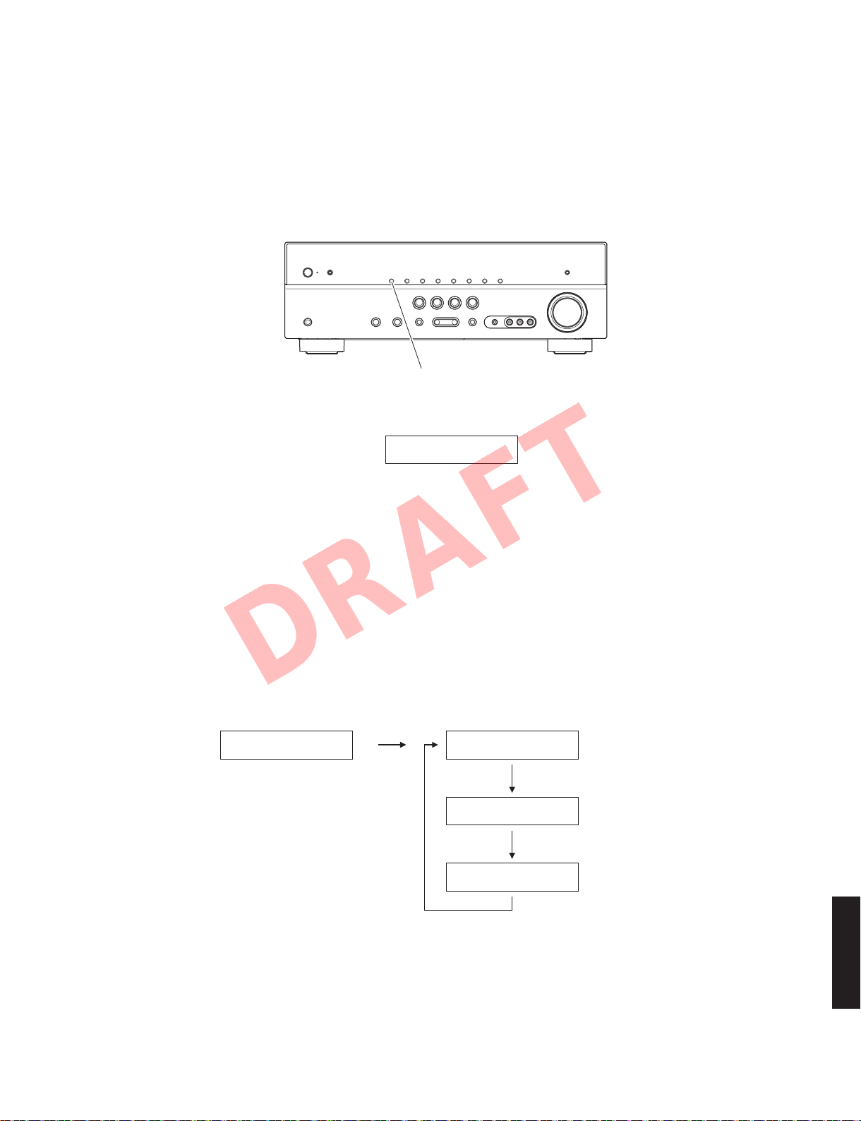
● Operation Procedures
1. While pressing the “INFO” key of this unit, connect
the power cable of this unit to the AC outlet. (Fig. 2)
The FIRMWARE UPDATE mode is activated and
“CDDA Upgrader” is displayed. (Fig. 2)
● 操作手順
1. 本機の “INFO” キーを押しながら、本機の電源コー
"INFO" key
Display /
CDDAUpgrader
表示
Fig. 2
ドを AC コンセントに接続します。(Fig.2)
ファームウェアアップデートモードが起動し、
“CDDAUpgrader” が表示されます。(Fig.2)
2. Play the firmware CD on the DVD/CD player.
Writing of the firmware starts automatically. (Fig. 3)
3. When writing of the firmware is completed,
“Update Success”, “Please...” and “Power off!!”
are displayed repeatedly. (Fig. 3)
Writing is started /
XXXXXXXXXX UpdateSuccess
XXXXXX
受信データ
: Received data
書き込み開始
2. DVD/CD プレーヤーでファームウェア CD を再生
します。ファームウェアの書き込みが自動で開始
されます。
3. ファームウェアの書き込み完了後、“Update
Success”、“Please...”、“Poweroff!!” が繰り返し表
示されます。(Fig.3)
Writing is completed /
Please...
Poweroff!!
書き込み完了
RX-V467/HTR-4063
23

RX-V467/HTR-4063
DRAFT
When the version of the firmware to be written
*
is the same as the one existing in this unit,
“Same Version”, “Please...” and “Power off!!”
are displayed repeatedly. (Updating is not
necessary.)
If the display remains unchanged for more
than 10 seconds after starting the firmware CD
play procedure, perform the firmware CD play
procedure again from the beginning.
If “FILE CORRUPTED” is displayed after
“Address:XXXXXX”, make sure that the written
data is not corrupted and perform Steps 1 to 3 of
“Operation Procedures” again.
If “Upgrade Failed” is displayed, perform
“operation procedures” again from the
beginning.
4. Press the “
power.
5. Eject the firmware CD from the DVD/CD player.
6. Start up the self-diagnostic function and check
that the firmware version and checksum are
the same as written ones. (See “Confirmation of
firmware version and checksum”)
” (Power) key of this unit to turn off the
※ 本機に既存のファームウェアと、書き込もう
としているファームウェアのバージョンが同
じ場合、“SameVersion”、“Please...”、“Power
off!!” の表示が繰り返されます。(アップデー
トの必要はありません。)
ファームウェア CD の再生開始後、10 秒以上
経過してもディスプレイ表示が変わらない場
合、ファームウェア CD の再生を最初からや
り直してください。
“Address:XXXXXX” の後に、“FILECORRUPTED”
が表示された場合、書き込みデータが破損して
いないかを確認し、“操作手順” の 1 から 3 ま
でをもう一度やり直してください。
“UpgradeFailed” が表示された場合、“操作手順”
を最初からやり直してください。
4. 本機の “
5. DVD/CD プレーヤーからファームウェア CD を取
り出します。
6. ダイアグを起動し、ファームウェアのバージョン
とチェックサムが、書き込まれたものと同じであ
ることを確認します。(“ファームウェアのバージョ
ンとチェックサムの確認” 参照)
”(パワー)キーを押して電源を切ります。
RX-V467/HTR-4063
24

RX-V467/HTR-4063
DRAFT
PC(RS-232C)を使用して書き込む方法WritingmethodusingPC(RS-232C)
● Required Tools
• Firmware downloader program
............Flash Development Toolkit 4.04 Basic.exe
Download the “fdtv404r00.exe”from the
*
specified source to the PC and execute it.
Perform operation according to the direction
on the display. The installation of the firmware
downloader program will be completed.
• Firmware .......................................V567_xxxx.mot
V567_xxxx.id
*
The firmware for RX-V467 is the same as one
for RX-V567.
• RS-232C cross cable “D-sub 9 pin female”
(Specifications)
Pin No.2 RxD Pin No.2 RxD
Pin No.3 TxD Pin No.3 TxD
Pin No.5 GND Pin No.5 GND
Pin No.7 RTS Pin No.7 RTS
Pin No.8 CTS Pin No.8 CTS
• RS-232C conversion adaptor (Part No.: WR492800)
● 必要なツール
・ ファームウェア書き込み用プログラム
...................FlashDevelopmentToolkit4.04Basic.exe
※ 指定のダウンロード先から “fdtv404r00.exe”
を PC にダウンロードし、それを実行します。
表示される指示通りに操作するとファーム
ウェア書き込み用プログラムのインストール
が完了します。
・ ファームウェア.........................................V567xxxx.mot
V567xxxx.id
※ RX-V467 用ファームウェアは、RX-V567 用の
ものと同じです。
・ RS-232C クロスケーブル “D-sub9pinメス”
(仕様)
Pin No.2 RxD Pin No.2 RxD
Pin No.3 TxD Pin No.3 TxD
Pin No.5 GND Pin No.5 GND
Pin No.7 RTS Pin No.7 RTS
Pin No.8 CTS Pin No.8 CTS
・ RS-232C 変換アダプター(部品番号:WR492800)
● Preparation and precautions
• Download the latest firmware from the specified
source to the older of the PC.
• Prepare the above specified RS-232C cross cable.
• While writing the firmware, keep the other application
software on the PC closed.
It is also recommended to keep the software on
the task tray closed as well.
● 準備と注意
・ 指定のダウンロード先から、最新のファームウェ
アを、PC のフォルダにダウンロードしてください。
・ RS-232C クロスケーブルは必ず上記仕様のものを
用意してください。
・ 書き込み時は、PC 上の他のアプリケーションソ
フトは閉じてください。
さらに、タスクトレイ上にあるソフトも閉じてお
くことを推奨します。
RX-V467/HTR-4063
25
RX-V467/HTR-4063
DRAFT
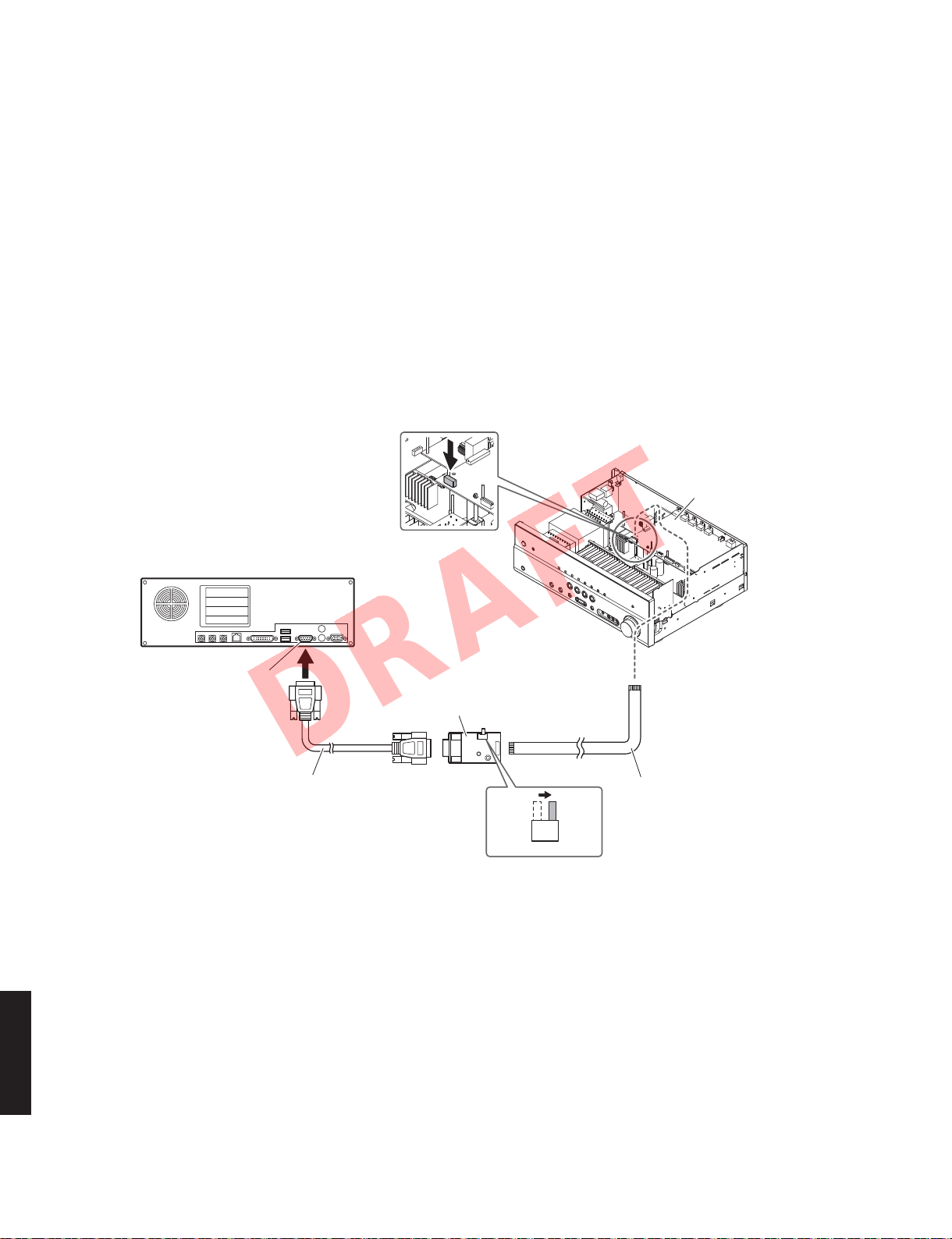
● Connection
Disconnect the power cable of this unit from the
*
AC outlet.
1. Remove the top cover.
(See “DISASSEMBLY PROCEDURES”)
2. Connect the writing port (CB27 of the DIGITAL P.C.B.)
of this unit to the serial port (RS-232C) of the PC
with RS-232C cross cable, RS-232C conversion
adaptor and flexible flat cable as shown below.
(Fig. 1)
3. Set the switch (SW7) of RS-232C conversion adaptor
as shown below. (Fig. 1)
PC
● 接続
※ 本機の電源コードを AC コンセントから抜いてく
ださい。
1. トップカバーを外します。(“分解手順” 参照)
2. 本機の書き込み用ポート(DIGITALP.C.B. の CB27)
と PC のシリアルポート(RS-232C)を下記のよう
に接続します。(Fig.1)
3. RS-232C 変換アダプターのスイッチ(SW7)を下
記のように設定します。(Fig.1)
Writing port (DIGITAL P.C.B. CB27)
書き込み用ポート(DIGITALP.C.B.CB27)
DIGITAL P.C.B.
RX-V467/HTR-4063
Serial port (RS-232C)
シリアルポート(RS-232C)
RS-232C cross cable
RS-232Cクロスケーブル
RS-232C conversion adaptor
RS-232C変換アダプター
SW7
FLASH
UCOM
OTHER
Fig. 1
Flexible flat cable (9P)
カード電線(9P)
For microprocessor
26
RX-V467/HTR-4063
DRAFT
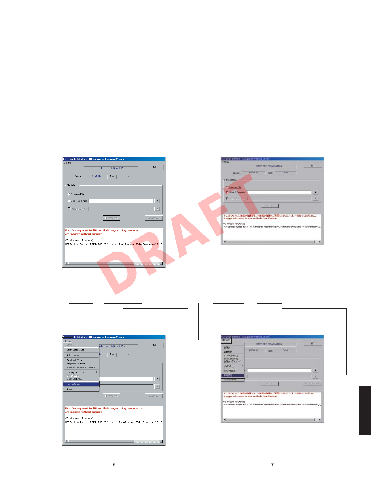
● Operation procedure
1. Connect the power cable of this unit to the AC outlet.
The power to this unit is supplied and the
microprocessor is in the writing mode.
2. Follow the procedure below to start up Flash
Development Toolkit 4.04 Basic.exe.
Click [start] → [All Programs] → [Renesas] → [Flash
Development Toolkit 4.04] → [Flash Development
Toolkit 4.04 Basic].
The screen appears as shown below. (Fig. 2)
* When Flash Development Toolkit 4.04 Basic.exe
is started with the PC for the first time, the “Choose
Device And Kernel” screen appears. (Fig. 4)
● 操作方法
1. 本機の電源コードを AC コンセントに接続します。
本機に電源が入り、マイコンが書き込みモードにな
ります。
2. 下記の手順で FlashDevelopmentToolkit4.04 Basic.
exe を起動します。
[スタート]→[すべてのプログラム]→[Renesas]
→[FlashDevelopmentToolkit4.04]→[Flash
DevelopmentToolkit4.04Basic]をクリックします。
下記の画面が表示されます。(Fig.2)
※ FlashDevelopmentToolkit4.04Basic.exe をパソコ
ンで初めて起動した場合、“デバイスとカーネルの
選択” 画面が表示されます。(Fig.4)
3. Click [Options] → [New Settings], and select the
Device and Port. (Fig. 3)
The “Choose Device And Kernel” screen appears.
(Fig. 4)
Fig. 2
3. [オプション]→[新規設定]をクリックし、Device、
Port を選択します。(Fig.3)
“デバイスとカーネルの選択” 画面が表示されます。
(Fig.4)
RX-V467/HTR-4063
Fig. 3
27
RX-V467/HTR-4063
DRAFT
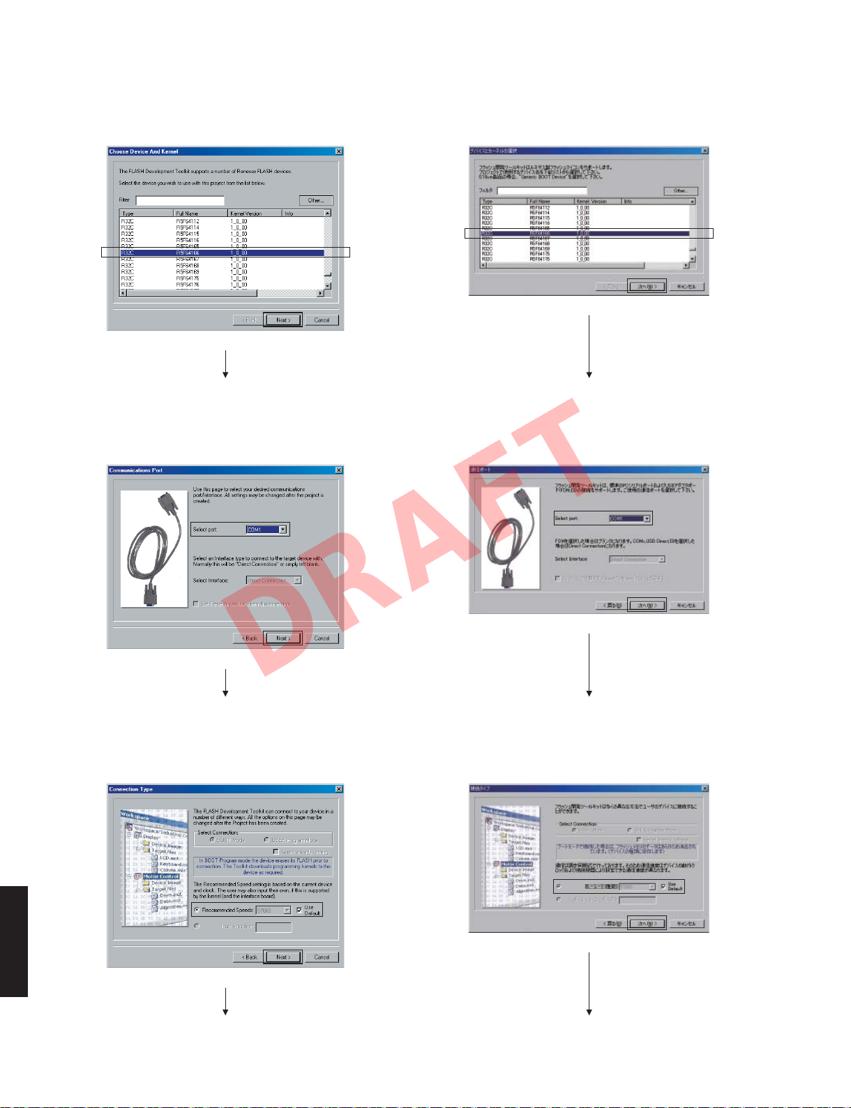
4. Select the device. (Fig. 4)
RX-V467/HTR-4063: R32C R5F64166 1_0_00
Click [Next]
5. Select the communications port of RS-232C. (Fig. 5)
4. デバイスを選択します。(Fig.4)
RX-V467/HTR-4063:R32CR5F641661000
[次へ]をクリック
Fig. 4
5. 接続している RS-2332C の通信ポートを選択します。
(Fig.5)
6. Select the Recommended Speeds “Use Default”.
(Fig. 6)
RX-V467/HTR-4063
Click [Next]
Click [Next]
[次へ]をクリック
Fig. 5
6. ボーレート “UseDefault” を選択します。(Fig.6)
[次へ]をクリック
Fig. 6
28
RX-V467/HTR-4063
DRAFT
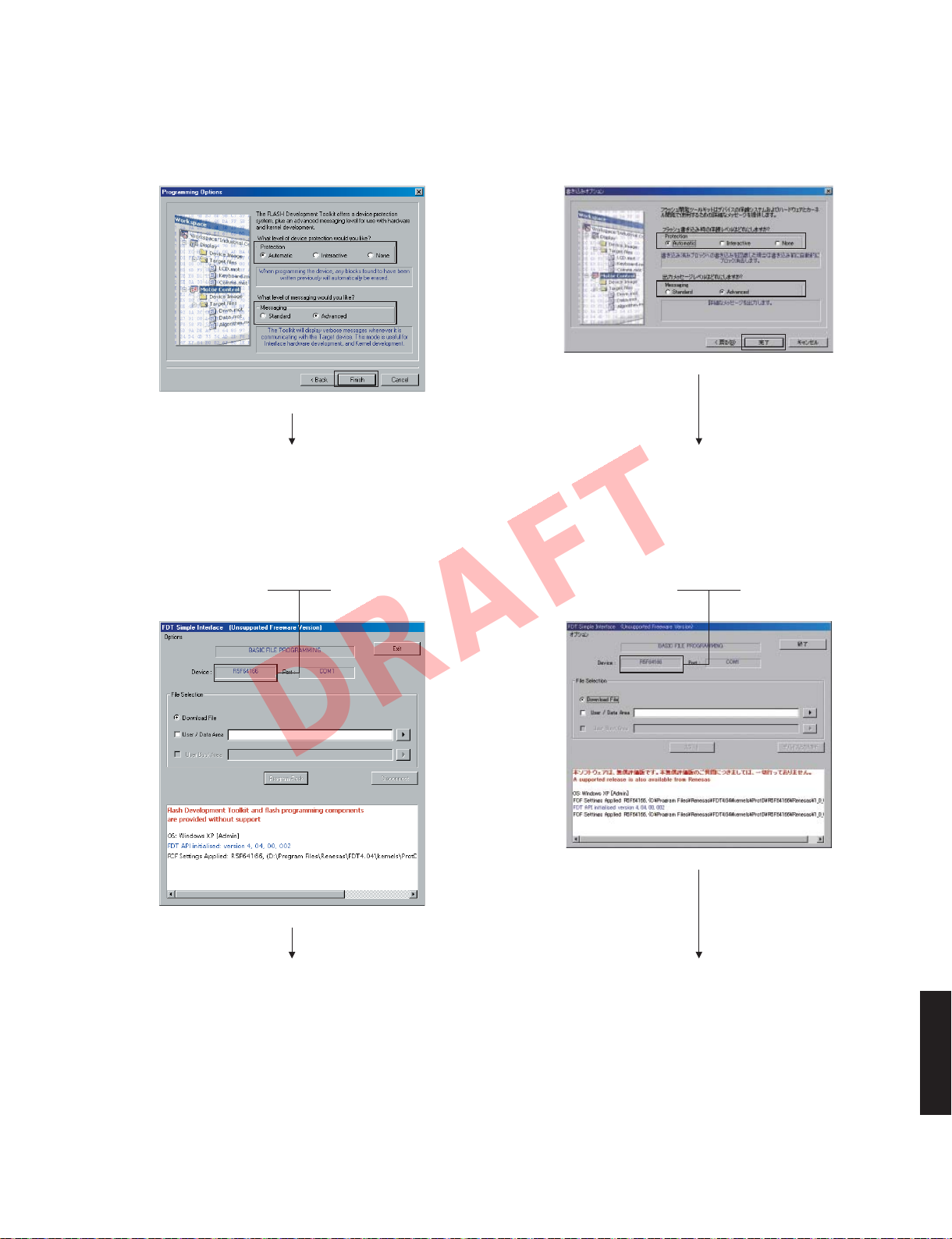
7. Select the Protection and Messaging. (Fig. 7)
Protection: Automatic
Messaging: Advanced
Click [Finish]
8. Check the Device.
When the Device is different from selected one, perform
the steps from 3 to 7 of the “Operation procedure”
again.
RX-V467/HTR-4063: R5F64166
7. Protection、Messaging を選択します。(Fig.7)
Protection:Automatic
Messaging:Advanced
[完了]をクリック
Fig. 7
8. Device
Device が選択されたものと異なっているときには、
「操作方法」の 3 から 7 までをもう一度やり直してく
ださい。
RX-V467/HTR-4063:R5F64166
を確認します。
Click [Finish]
Fig. 8
[完了]をクリック
RX-V467/HTR-4063
29

RX-V467/HTR-4063
DRAFT
9. Click [Options] to select the AutoDisconnect. (Fig. 9)
10. Click [▶] → [Browse], and select the firmware name.
(Fig. 10)
Firmware: V567_xxxx.mot
The firmware for RX-V467 is the same as one
*
for RX-V567.
9.
[オプション]をクリックして自動切断を選択します。
Fig. 9
(
Fig. 9
10.[▶]→[参照]をクリックし、書き込むファームウェ
)
アを選択します。(Fig.10)
ファームウェア:V567xxxx.mot
※ RX-V467 用ファームウェアは、RX-V567
用のものと同じです。
Fig. 10
RX-V467/HTR-4063
30
 Loading...