

Page 1

RX-V396
Natural Sound AV Receiver
Ampli-tuner audio-vidéo
U C A
OWNER’S MANUAL
MODE D’EMPLOI
Page 2

SAFETY INSTRUCTIONS
CAUTION
RISK OF ELECTRIC SHOCK
DO NOT OPEN
CAUTION: TO REDUCE THE RISK OF
ELECTRIC SHOCK, DO NOT REMOVE
COVER (OR BACK). NO USER-SERVICEABLE
PARTS INSIDE. REFER SERVICING TO
QUALIFIED SERVICE PERSONNEL.
• Explanation of Graphical Symbols
The lightning flash with arrowhead symbol,
within an equilateral triangle, is intended to
alert you to the presence of uninsulated
“dangerous voltage” within the product’s
enclosure that may be of sufficient magnitude
to constitute a risk of electric shock to persons.
The exclamation point within an equilateral
triangle is intended to alert you to the presence
of important operating and maintenance
(servicing) instructions in the literature
accompanying the appliance.
WARNING
TO REDUCE THE RISK OF FIRE OR
ELECTRIC SHOCK, DO NOT EXPOSE THIS UNIT TO
RAIN OR MOISTURE.
1 Read Instructions – All the safety and operating
instructions should be read before the unit is operated.
2 Retain Instructions – The safety and operating
instructions should be retained for future reference.
3 Heed Warnings – All warnings on the unit and in the
operating instructions should be adhered to.
4 Follow Instructions – All operating and other instructions
should be followed.
5 Water and Moisture – The unit should not be used near
water – for example, near a bathtub, washbowl, kitchen
sink, laundry tub, in a wet basement, or near a swimming
pool, etc.
6 Carts and Stands – The unit should be used only with a
cart or stand that is recommended by the
manufacturer.
6A A unit and cart combination should be
moved with care. Quick stops, excessive
force, and uneven surfaces may cause
the unit and cart combination to overturn.
7 Wall or Ceiling Mounting – The unit should be mounted to
a wall or ceiling only as recommended by the
manufacturer.
8 Ventilation – The unit should be situated so that its
location or position does not interfere with its proper
ventilation. For example, the unit should not be situated
on a bed, sofa, rug, or similar surface, that may block the
ventilation openings; or placed in a built-in installation,
such as a bookcase or cabinet that may impede the flow
of air through the ventilation openings.
9 Heat – The unit should be situated away from heat
sources such as radiators, stoves, or other appliances
that produce heat.
10 Power Sources – The unit should be connected to a
power supply only of the type described in the operating
instructions or as marked on the unit.
11 Power-Cord Protection – Power-supply cords should be
routed so that they are not likely to be walked on or
pinched by items placed upon or against them, paying
particular attention to cords at plugs, convenience
receptacles, and the point where they exit from the unit.
12 Cleaning – The unit should be cleaned only as
recommended by the manufacturer.
13 Nonuse Periods – The power cord of the unit should be
unplugged from the outlet when left unused for a long
period of time.
14 Object and Liquid Entry – Care should be taken so that
objects do not fall into and liquids are not spilled into the
inside of the unit.
15 Damage Requiring Service – The unit should be serviced
by qualified service personnel when:
A. The power-supply cord or the plug has been
damaged; or
B. Objects have fallen, or liquid has been spilled into the
unit; or
C. The unit has been exposed to rain; or
D. The unit does not appear to operate normally or exhibits
a marked change in performance; or
E. The unit has been dropped, or the cabinet damaged.
16 Servicing – The user should not attempt to service the
unit beyond those means described in the operating
instructions. All other servicing should be referred to
qualified service personnel.
17 Power Lines – An outdoor antenna should be located
away from power lines.
18 Grounding or Polarization – Precautions should be taken
so that the grounding or polarization is not defeated.
CAUTION
Page 3

19 For US customers only:
Outdoor Antenna Grounding – If an outside antenna is
connected to this unit, be sure the antenna system is
grounded so as to provide some protection against
voltage surges and built-up static charges. Article 810 of
the National Electrical Code, ANSI/NFPA 70, provides
information with regard to proper grounding of the mast
and supporting structure, grounding of the lead-in wire to
an antenna discharge unit, size of grounding conductors,
location of antenna discharge unit, connection to
grounding electrodes, and requirements for the
grounding electrode.
Note to CATV system installer:
This reminder is provided to call the CATV system
installer’s attention to Article 820-40 of the NEC that
provides guidelines for proper grounding and, in particular,
specifies that the cable ground shall be connected to the
grounding system of the building, as close to the point of
cable entry as practical.
FCC INFORMATION (for US customers only)
EXAMPLE OF ANTENNA GROUNDING
MAST
GROUND
CLAMP
ELECTRIC
SERVICE
EQUIPMENT
NEC
– NATIONAL ELECTRICAL CODE
SAFETY INSTRUCTIONS
ANTENNA
LEAD IN
WIRE
ANTENNA
DISCHARGE UNIT
(NEC SECTION 810–20)
GROUNDING CONDUCTORS
(NEC SECTION 810–21)
GROUND CLAMPS
POWER SERVICE GROUNDING
ELECTRODE SYSTEM
(NEC ART 250. PART H)
INTRODUCTION PREP ARA TION
1. IMPORTANT NOTICE : DO NOT MODIFY THIS UNIT!
This product, when installed as indicated in the
instructions contained in this manual, meets FCC
requirements. Modifications not expressly approved by
Yamaha may void your authority, granted by the FCC,
to use the product.
2. IMPORTANT : When connecting this product to
accessories and/or another product use only high
quality shielded cables. Cable/s supplied with this
product MUST be used. Follow all installation instructions. Failure to follow instructions could void your FCC
authorization to use this product in the USA.
3. NOTE : This product has been tested and found to
comply with the requirements listed in FCC Regulations, Part 15 for Class “B” digital devices. Compliance
with these requirements provides a reasonable level of
assurance that your use of this product in a residential
environment will not result in harmful interference with
other electronic devices.
This equipment generates/uses radio frequencies and,
if not installed and used according to the instructions
found in the users manual, may cause interference
harmful to the operation of other electronic devices.
Compliance with FCC regulations does not guarantee
that interference will not occur in all installations. If
this product is found to be the source of interference,
which can be determined by turning the unit “OFF”
and “ON”, please try to eliminate the problem by using
one of the following measures:
Relocate either this product or the device that is being
affected by the interference.
Utilize power outlets that are on different branch
(circuit breaker or fuse) circuits or install AC line filter/
s.
In the case of radio or TV interference, relocate/
reorient the antenna. If the antenna lead-in is 300
ohm ribbon lead, change the lead-in to coaxial type
cable.
If these corrective measures do not produce satisfactory results, please contact the local retailer authorized to distribute this type of product. If you can not
locate the appropriate retailer, please contact Yamaha
Electronics Corp., U.S.A. 6660 Orangethorpe Ave,
Buena Park, CA 90620.
The above statements apply ONLY to those products
distributed by Yamaha Corporation of America or its
subsidiaries.
ADV ANCED OPERA
TION APPENDIX
We Want You Listening For A Lifetime
YAMAHA and the Electronic Industries Association’s
Consumer Electronics Group want you to get the most out of
your equipment by playing it at a safe level. One that lets the
sound come through loud and clear without annoying blaring
or distortion – and, most importantly, without affecting your
sensitive hearing.
Since hearing damage from loud sounds is often
undetectable until it is too late, YAMAHA and the
Electronic Industries Association’s Consumer
Electronics Group recommend you to avoid
prolonged exposure from excessive volume
levels.
EnglishBASIC OPERATION
CAUTION
Page 4

CAUTION: READ THIS BEFORE OPERATING YOUR UNIT.
1. To assure the finest performance, please read this
manual carefully. Keep it in a safe place for future
reference.
2. Install this unit in a cool, dry, clean place — away
from windows, heat sources, sources of excessive
vibration, dust, moisture and cold. Avoid sources of
humming (transformers, motors). To prevent fire or
electrical shock, do not expose the unit to rain or
water.
3. Never open the cabinet. If something drops into the
unit, contact your dealer.
4. Do not use force on switches, controls or connection
wires. When moving the unit, first disconnect the
power cord and then the wires connected to other
component. Never pull the wires themselves.
5. The openings on the cover assure proper ventilation
of the unit. If these openings are obstructed, the
temperature inside the unit will rise rapidly.
Therefore, avoid placing objects against these
openings, and install the unit in a well-ventilated area
to prevent fire and damage.
6. The voltage used must be the same as that specified
on this unit. Using this unit with a higher voltage than
specified is dangerous and may result in fire or other
accidents. YAMAHA will not be held responsible for
any damage resulting from the use of this unit with a
voltage other than that specified.
7. Digital signals generated by this unit may interfere
with other component such as tuners, receivers and
TVs. Move this unit farther away from such
component if interference is observed.
8. Always set VOLUME to the “m” position before
starting the audio source play. Increase the volume
gradually to an appropriate level after playback has
been started.
9. Do not attempt to clean the unit with chemical
solvents; this might damage the finish. Use a clean,
dry cloth.
10. Be sure to read the “TROUBLESHOOTING” section
regarding common operating errors before
concluding that the unit is faulty.
11. When not planning to use this unit for a long period
of time (e.g., a vacation), disconnect the AC power
cord from the wall outlet.
12. To prevent lightning damage, disconnect the AC
power cord and disconnect the antenna cable when
there is an electrical storm.
13. Grounding or polarization — Precautions should be
taken so that the grounding or polarization of the unit
is not defeated.
14. AC outlet — Do not connect audio component to the
AC outlet on the rear panel if that component
requires more power than the outlet is rated to
provide.
This unit is not disconnected from the AC power source
as long as it is connected to the wall outlet, even if this
unit itself is turned off. This state is called the standby
mode. In this state, this unit is designed to consume a
very small quantity of power.
IMPORTANT
Please record the serial number of this unit in the space
below.
MODEL:
Serial No.:
The serial number is located on the rear of the unit.
Retain this Owner’s Manual in a safe place for future
reference.
WARNING
TO REDUCE THE RISK OF FIRE OR ELECTRIC
SHOCK, DO NOT EXPOSE THIS UNIT TO RAIN OR
MOISTURE.
FOR CANADIAN CUSTOMERS
To prevent electric shock, match wide blade of plug to
wide slot and fully insert.
This Class B digital apparatus complies with Canadian
ICES-003.
CAUTION
Page 5

INTRODUCTION
FEATURES
5-Channel Power Amplification
◆ Minimum RMS Output
(0.06% THD, 20 Hz – 20 kHz)
Main: 60 W + 60 W (8 Ω)
Center: 60 W (8 Ω)
Rear: 60 W + 60 W (8 Ω)
Multi-mode Digital Sound Field
Processing
◆ Digital Sound Field Processor (DSP)
◆ Dolby Digital Decoder
◆ Dolby Pro Logic Decoder
◆ CINEMA DSP: Theater-like Sound Experience by
the Combination of YAMAHA DSP Technology
and Dolby Digital or Dolby Pro Logic
◆ Automatic Input Balance Control for Dolby Pro
Logic decoding
Sophisticated FM/AM Tuner
◆ 40-Station Random Access Preset Tuning
◆ Automatic Preset Tuning
◆ Preset Station Shifting Capability (Preset Editing)
Other Features
◆ “SET MENU” which Provides You with 10 Items
for Optimizing This Unit for Your Audio/Video
System
◆ Test Tone Generator for Easier Speaker Balance
Adjustment
◆ 6-Channel External Decoder Input for Other Future
Formats
◆ 2 Optical/1 Coaxial Digital Signal Input Terminals
◆ SLEEP Timer
◆ Remote Control with Preset Manufacturer Codes
CONTENTS
INTRODUCTION
FEATURES .................................................................. 1
CONTENTS ................................................................. 1
GETTING STARTED .................................................2
CONTROLS AND FUNCTIONS ............................... 4
PREPARATION
SPEAKER SETUP....................................................... 8
CONNECTIONS.......................................................... 9
ADJUSTING THE SPEAKER BALANCE ............ 17
BASIC OPERATION
PLA YING A SOURCE .............................................. 19
DIGITAL SOUND FIELD PROCESSOR (DSP)
EFFECT .................................................................. 22
SOUND FIELD PROGRAM .................................... 23
TUNING ..................................................................... 26
RECORDING A SOURCE ON TAPE, MD OR
VIDEO CASSETTE ............................................... 30
ADVANCED OPERATION
SET MENU................................................................. 31
DELAY TIME AND SPEAKER
OUTPUT LEVELS ................................................. 35
SLEEP TIMER .......................................................... 37
PRESET REMOTE CONTROL .............................. 38
INTRODUCTION PREP ARA TION
ADV ANCED OPERA
TION APPENDIX
Manufactured under license from Dolby
Laboratories. “Dolby”, “Pro Logic” and the
double-D symbol are trademarks of Dolby
Laboratories. Confidential Unpublished Works.
©1992 – 1997 Dolby Laboratories, Inc. All
rights reserved.
APPENDIX
TROUBLESHOOTING ............................................ 45
SPECIFICATIONS.................................................... 48
GLOSSARY................................................................ 49
INDEX ........................................................................ 50
y indicates a tip for your operation.
EnglishBASIC OPERATION
1
Page 6
GETTING STARTED
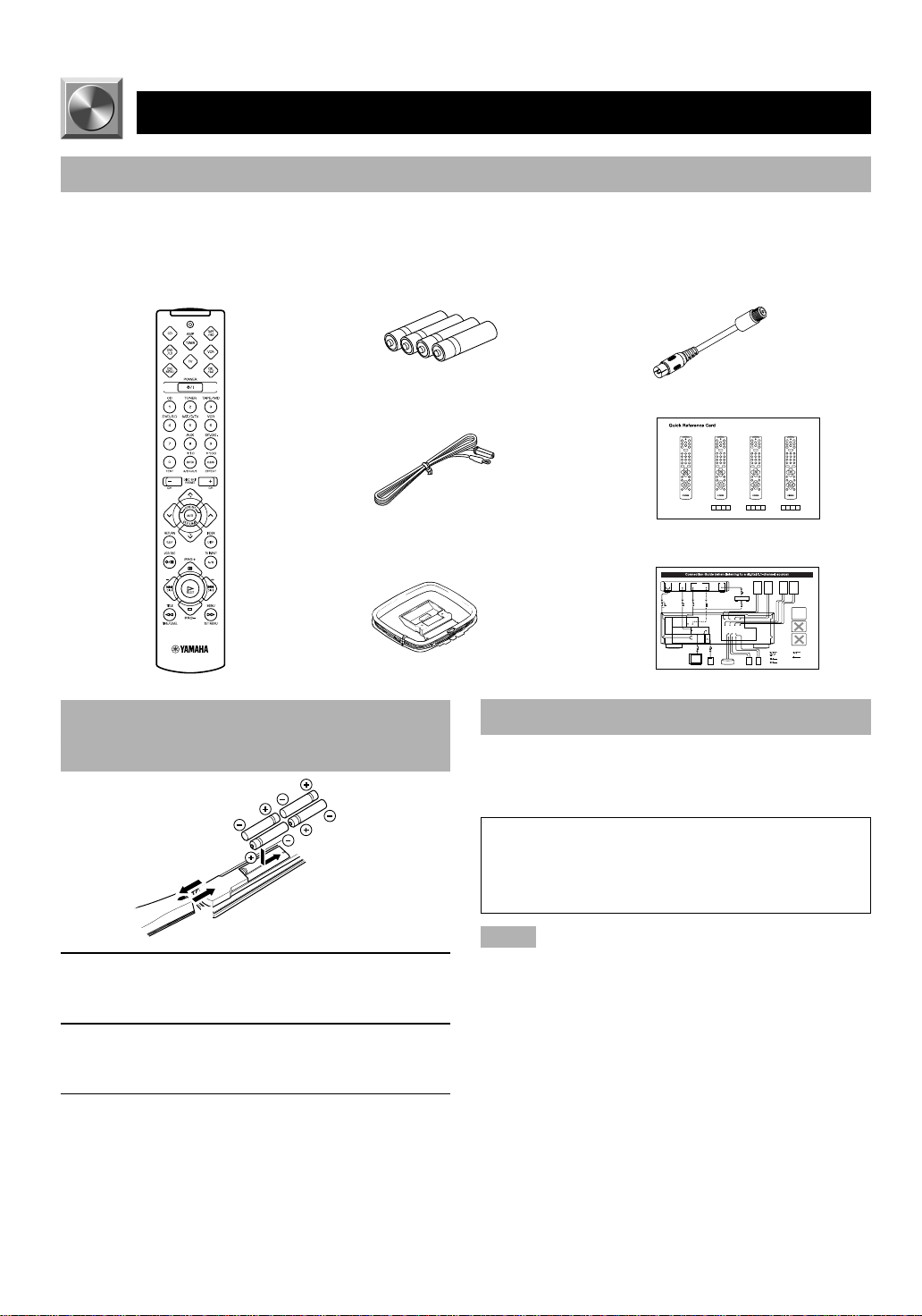
Checking the Package Contents
Check that the following items are included in your package.
Remote control Batteries (AAA, R03, UM-4 type) Antenna adapter
Indoor FM antenna Quick reference card
AM loop antenna
Battery Installation in the Remote
Control
Battery Replacement
If the remote control operates only when it is close to the
unit, the batteries are weak. Replace all the batteries with
new ones.
(U.S.A. and Canada models only)
Connection guide
2
1
3
1 Turn the remote control over and slide the
battery compartment cover in the direction of
the arrow.
2 Insert the batteries (AAA, R03 or UM-4 type)
according the polarity markings on the inside
of the battery compartment.
3 Close the battery compartment cover.
2
Be sure to replace the batteries within about two minutes.
If it takes longer than two minutes, the codes preset for
the remote control will return to the factory settings.
(Refer to pages 38 to 44 about the remote control.)
Notes
• Use only AAA, R03 or UM-4 batteries for replacement.
• Be sure the battery polarity is correct. (See the illustration inside
the battery compartment.)
• Remove the batteries if the remote control will not be used for an
extended period of time.
• If the batteries have leaked, dispose of them immediately. Avoid
touching the leaked material or letting it come into contact with
clothing, etc. Clean the battery compartment thoroughly before
installing new batteries.
Page 7
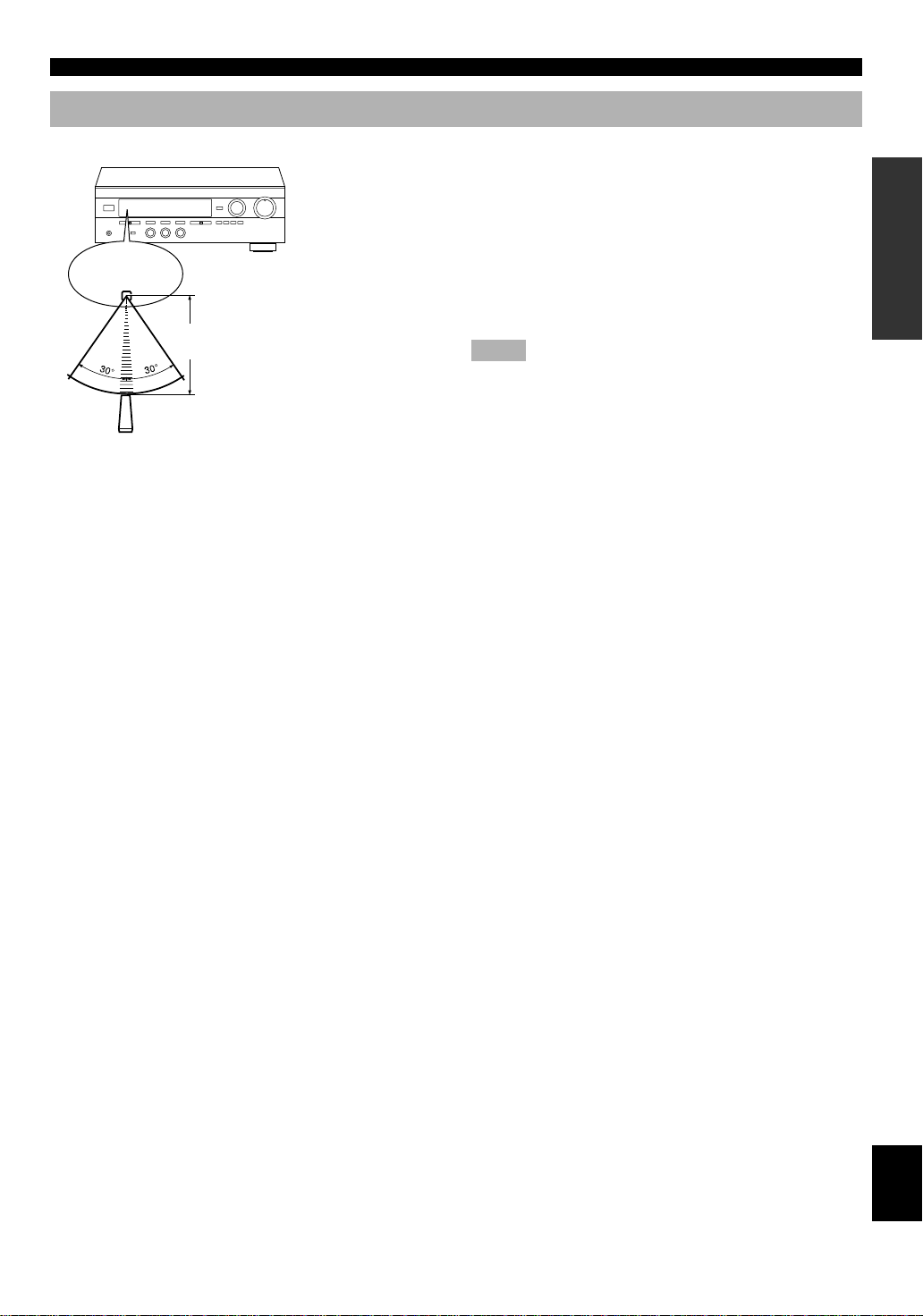
Using the Remote Control
Remote control
sensor
Within approximately 6 m
(20 feet)
GETTING STARTED
The remote control transmits a directional infrared beam. Be
sure to aim the remote control directly at the infrared sensor
during operation. When the sensor is covered or there is a
large object between the remote control and the sensor, the
sensor cannot receive signals. The sensor may not be able to
receive signals properly when it is exposed to direct sunlight
or a strong artificial light (such as a fluorescent or strobe
light). In this case, change the direction of the light or
reposition the unit to avoid direct lighting.
Notes
• Handle the remote control with care.
• Do not spill water, tea or other liquids on the remote control.
• Do not drop the remote control.
• Do not leave or store the remote control in the following
conditions:
– high humidity or temperature such as near a heater, stove or
bath;
– dusty places; or
– extremely low temperature.
INTRODUCTION PREP ARA TION
ADV ANCED OPERA
TION APPENDIX
EnglishBASIC OPERATION
3
Page 8
CONTROLS AND FUNCTIONS
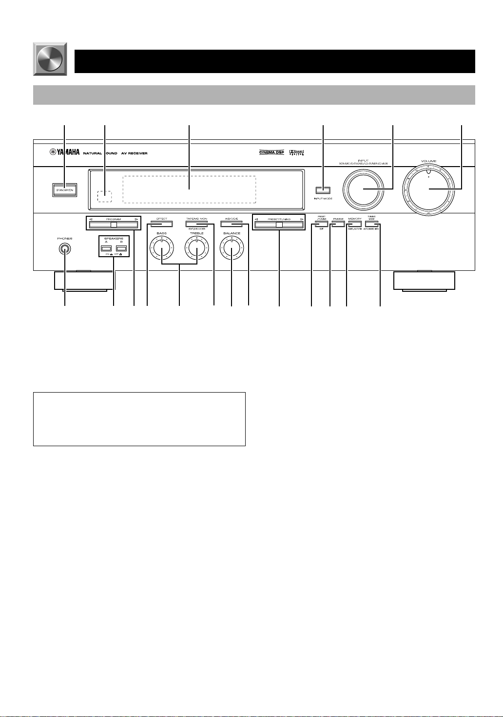
Front Panel
12 3 4 65
+
–
+
–
LR
7890qwertyu i o
1 STANDBY/ON
Press this switch to turn on the power of this unit or to set
this unit in the standby mode. Before turning the power on,
set VOLUME to the “m” position.
Standby mode
In this mode, this unit consumes a very small quantity of
power to receive infrared-signals from the remote
control.
2 Remote control sensor
This receives signals from the remote control.
3 Display
This shows various information. (Refer to page 6 for
details.)
4 INPUT MODE
Press this button to select the input mode between AUTO
and ANALOG for the DVD/LD, TV/digital TV and satellite
tuner sources.
5 INPUT
Turn this selector to select the input source (VCR, SAT/DTV, DVD/LD, TUNER, CD, AUX) that you want to listen
to or watch. The name of the selected input source appears
on the display.
6 VOLUME
Turn this control to turn up or down the volume.
7 PHONES jack
Connect the headphones to the PHONES jack. You can
listen to the sound to be output from the main speakers
through the headphones.
When using headphones only, set both SPEAKERS A and B
to the OFF position and press EFFECT to turn off the effect
speakers (center and rear) (so that no DSP program
indicator lights up on the display).
8 SPEAKERS
Set A or B (or both A and B) to the ON position for the main
speaker system (connected to this unit) that you want to use.
Set the button(s) to the OFF position for the main speaker
system that you don’t want to use.
9 PROGRAM selector
Press l or h to select a DSP program when the effect
speakers (center and rear) are turned on. The selected
program indicator lights up on the display.
0 EFFECT
Press this button to turn on or off the effect speakers (center
and rear). If you turn them off, all Dolby Digital audio
signals are directed to the right and left main speakers. In
that case, the output levels of the right and left speakers may
not match.
4
Page 9

CONTROLS AND FUNCTIONS
q Tone controls
These controls are only effective for the sound from the
main speakers.
a) BASS
Turn this control clockwise to increase or counterclockwise
to decrease the low-frequency response. The “0” position
produces a flat response.
b) TREBLE
Turn this control clockwise to increase or counterclockwise
to decrease the high-frequency response. The “0” position
produces a flat response.
w TAPE/MD MON / EXT. DECODER
Press this button to select a tape or an MD source. The
“TAPE/MD MONITOR” indicator lights up on the display.
When you press the button next, the “TAPE/MD
MONITOR” indicator goes off, “EXT. DECODER” appears
on the display and you can listen to a source connected to
the EXTERNAL DECODER INPUT terminals.
e BALANCE
This control is only effective for the sound from the main
speakers.
Turn the control to adjust the balance of the output volume
from the right and left main speakers to compensate for
sound imbalance caused by the speaker location or listening
room conditions.
r A/B/C/D/E
Press this button to select one of a group (A to E) of preset
stations.
t PRESET/TUNING
When “ z ” appears
This button is used to select a preset station number (1 to 8).
Press h to select a higher and l to select a lower preset
station number.
When “ z ” goes off
This button is used for tuning. Press h to tune in to higher
frequencies, and l to tune in to lower frequencies.
y PRESET/TUNING, EDIT
Press this button to turn on or off “ z ” on the display and
switch the function between for storing a broadcasting
station (preset tuning) and for tuning. This button is also
used to exchange the assignment of two preset stations with
each other.
u FM/AM
Press this button to switch the reception band between FM
and AM.
i MEMORY (MAN’L/AUTO FM)
Press this button to store the broadcasting stations. Hold
down this button for more than three seconds to begin
automatic preset tuning.
o TUNING MODE (AUTO/MAN’L MONO)
Press this button to switch the tuning mode between
automatic and manual. To use the automatic tuning method,
press this button so that the “AUTO” indicator lights up on
the display. To use the manual tuning method, press this
button so that the “AUTO” indicator goes off.
INTRODUCTION PREP ARA TION
ADV ANCED OPERA
TION APPENDIX
EnglishBASIC OPERATION
5
Page 10

9
CONTROLS AND FUNCTIONS
Display
12 3 4
67
8
1 g and o indicators
“ g ” lights up when the built-in Dolby Digital
decoder is on and the signals of the selected source are
encoded with Dolby Digital. “ o ” lights up when
the built-in Dolby Pro Logic decoder is on.
2 DSP program indicators
The name of the selected DSP program lights up.
3 Multi-information display
This display shows various information: for example the
name of the selected input source and the various settings
during adjustment with the SET MENU. The current station
frequency and band (FM or AM) also appear when the tuner
is selected as the input source.
4 SLEEP indicator
This lights up while the built-in SLEEP timer is on.
5 TAPE/MD MONITOR indicator
This lights up when the tape deck or MD recorder, etc. is
selected as the input source by pressing TAPE/MD MON /
EXT. DECODER (or TAPE/MD).
5
0
6 x indicator
“ x ” lights up when the built-in digital sound
field processor is on.
7 MEMORY indicator
This flashes for about five seconds after pressing
MEMORY. During this period, the displayed station can be
stored in the memory.
8 AUTO indicator
This lights up when the unit is in the automatic tuning
mode.
9 STEREO indicator
This lights up when an FM stereo broadcast with sufficient
signal strength is being received.
0 Signal-level indicator
This indicates the signal level of the station being received.
If multipath interference is detected, the indication
decreases.
6
Page 11
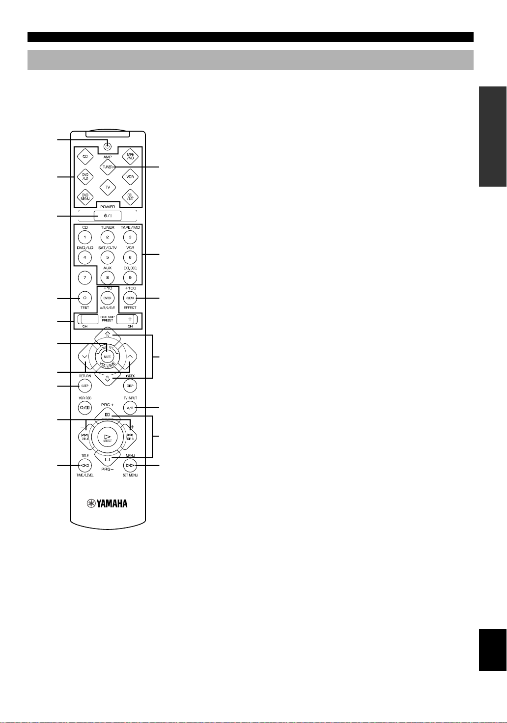
Remote Control
CONTROLS AND FUNCTIONS
This section describes basic operation of this unit with the
remote control. First, press AMP(TUNER) on the
component selector. Refer to “PRESET REMOTE
CONTROL” on page 38 for full details.
1
Press AMP(TUNER).
2
3
q
4
w
5
6
TV VOLUME
7
8
TV INPUT
9
e
0
r
1 Indicator
This flashes in red when pressing a button on the remote
control. If it flashes rapidly several times, press the selected
button again.
2 Component selector buttons
Press one of these buttons which corresponds to the
component you want to control with the remote control.
(The proper code must be set for your component. Refer to
“Setup codes” on page 43.) When the component selector
button has been pressed, the remote control is set to that
component operation mode.
3 POWER
Each time you press this button, the unit switches between
the power on and standby mode.
4 TEST
Press this button to output the test tone for each speaker.
5 A/B/C/D/E, PRESET +/–
These buttons are used to select a preset station.
A/B/C/D/E: To select one of a group (A to E) of preset
stations
PRESET +/–: To select a preset station number (1 to 8)
6 MUTE
Press this button to mute the sound. To cancel mute, press
this button again.
7 VOLUME
These buttons are used to adjust the volume level.
u: To turn up the volume
d: To turn down the volume
8 SLEEP
Press this button to set the SLEEP timer.
9 +/–
These buttons adjust the settings of the SET MENU and
TIME/LEVEL mode.
0 TIME/LEVEL
Press this button to select the items in the TIME/LEVEL
mode.
q Input selector buttons
These buttons select the input source.
CD: To play a CD
TUNER: To listen to an FM or AM broadcast
TAPE/MD: To play a tape or MD
DVD/LD: To play a DVD or LD
SAT/D-TV: To watch a TV or satellite broadcast
VCR: To play a video cassette
AUX: To use another audio component
EXT. DEC.: To play other multi-channel source
w EFFECT
Press this button to turn on or off the effect speakers (center
and rear).
e PRG+, PRG–
Press these buttons to select a DSP program.
r SET MENU
Press this button to select the items in the SET MENU.
INTRODUCTION PREP ARA TION
ADV ANCED OPERA
TION APPENDIX
EnglishBASIC OPERATION
7
Page 12

PREPARATION
SPEAKER SETUP
Speakers to Be Used
This unit is designed to provide the best sound-field quality
with a 5-speaker system, using main speakers, rear speakers
and a center speaker. If you use different brands of speakers
(with different tonal qualities) in your system, the tone of a
moving human voice and other types of sound may not shift
smoothly. We recommend that you use speakers from the
same manufacture or speakers with the same tonal quality.
The main speakers are used for the main source sound plus
the effect sounds. They will probably be the speakers from
your present stereo system. The rear speakers are used for
the effect and surround sounds, and the center speaker is for
the center sounds (dialog, vocals, etc.). If for some reason it
is not practical to use a center speaker, you can do without
it. Best results, however, are obtained with the full system.
The main speakers should be high-performance models and
have enough power-handling capacity to accept the
maximum output of your audio system. The other speakers
do not have to be equal to the main speakers. For precise
sound localization, however, it is ideal to use highperformance models that can reproduce sounds over the full
range for the center speaker and the rear speakers.
■ Use of a subwoofer expands your
sound field
It is also possible to further expand your system with the
addition of a subwoofer. The use of a subwoofer is effective
not only for reinforcing bass frequencies from any or all
channels, but also for reproducing the LFE (low frequency
effect) channel with high fidelity when playing back a
source encoded with Dolby Digital. The YAMAHA Active
Servo Processing Subwoofer System is ideal for natural and
lively bass reproduction.
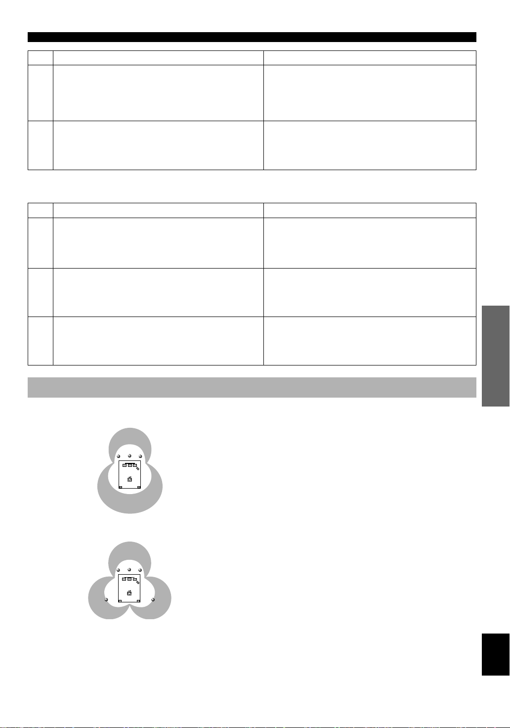
Speaker Placement
Refer to the following diagram when you place the
speakers.
Main
speaker (L)
Center speaker
■ Main speakers
Place the right and left main speakers an equal distance
from the ideal listening position. The distance of each
speaker from each side of the TV monitor should be the
same.
■ Rear speakers
Place these speakers behind your listening position, facing
slightly inwards, nearly 1.8 m (approx. 6 feet) above the
floor.
■ Center speaker
Align the front face of the center speaker with the front face
of your TV monitor. Place the speaker as close to the
monitor as possible, such as directly over or under the
monitor and centrally between the main speakers.
Note
• If the center speaker is not used, the sound will be heard from the
right and left main speakers. In that case, “CENTER SP” in the
SET MENU is set to the NONE position. (Refer to page 32 for
details.)
Main speaker (R)
Rear speaker (R)
Subwoofer
1.8 m
Rear speaker (L)
■ Subwoofer
The position of the subwoofer is not so critical, because low
bass sounds are not highly directional. But it is better to
place the subwoofer near the main speakers. Turn it slightly
toward the center of the room to reduce the wall reflections.
CAUTION
Some types of speakers interfere with a TV monitor. If
this problem occurs, move the speakers away from the
monitor. If you cannot avoid installing the center speaker
or subwoofer near the TV monitor, use magnetically
shielded speakers.
8
Page 13

CONNECTIONS
V V
C C
L
R
L
R
Before Connecting Components
CAUTION
Never connect this unit and other components to mains power until all connections between components have been
completed.
Be sure all connections are made correctly, that is to say L (left) to L, R (right) to R, “+” to “+” and “–” to “–”. Some
components require different connection methods and have different terminal names. Refer to the instructions for each
component to be connected to this unit.
When you connect other YAMAHA audio components (such as a tape deck, MD recorder and CD player or changer), connect
it to the terminals with the same number labels as !, #, $ etc. YAMAHA applies this labeling system to all its products.
Use RCA-type pin plug cables for connecting audio/video components with the exception described later.
The input and output terminals for pin plugs can be distinguished as follows:
Yellow video signals (composite)
White analog audio signals for the left channel
Red analog audio signals for the right channel
coaxial digital signals
After completing all connections, check them again to make sure they are correct.
INTRODUCTION
PREP ARA TION
Connecting the
Antenna (page 10)
Connecting an Audio
Component (page 12)
Connecting to an External
Decoder (page 12)
Connecting a Video
Component (page 13)
Connecting Speakers
(page 14)
L
MAIN
––++
R
REAR
L
R
CENTER
(SURROUND)
+
–
+
IMPEDANCE SELECTOR
switch (page 16)
Connecting the Power
Supply Cords (page 16)
A
B
SET BEFORE POWER ON
MAIN A OR B:4ΩMIN. /SPEAKER
A + B:8ΩMIN. /SPEAKER
CENTER : 6ΩMIN. /SPEAKER
REAR :6ΩMIN. /SPEAKER
MAIN A OR B:8ΩMIN. /SPEAKER
A + B:I6ΩMIN. /SPEAKER
CENTER : 8ΩMIN. /SPEAKER
REAR :8ΩMIN. /SPEAKER
–
(U.S.A. model)
MAINS
120 V 60Hz
100W MAX. TOTAL
SWITCHED
ADV ANCED OPERA
TION APPENDIX
EnglishBASIC OPERATION
9
Page 14
CONNECTIONS
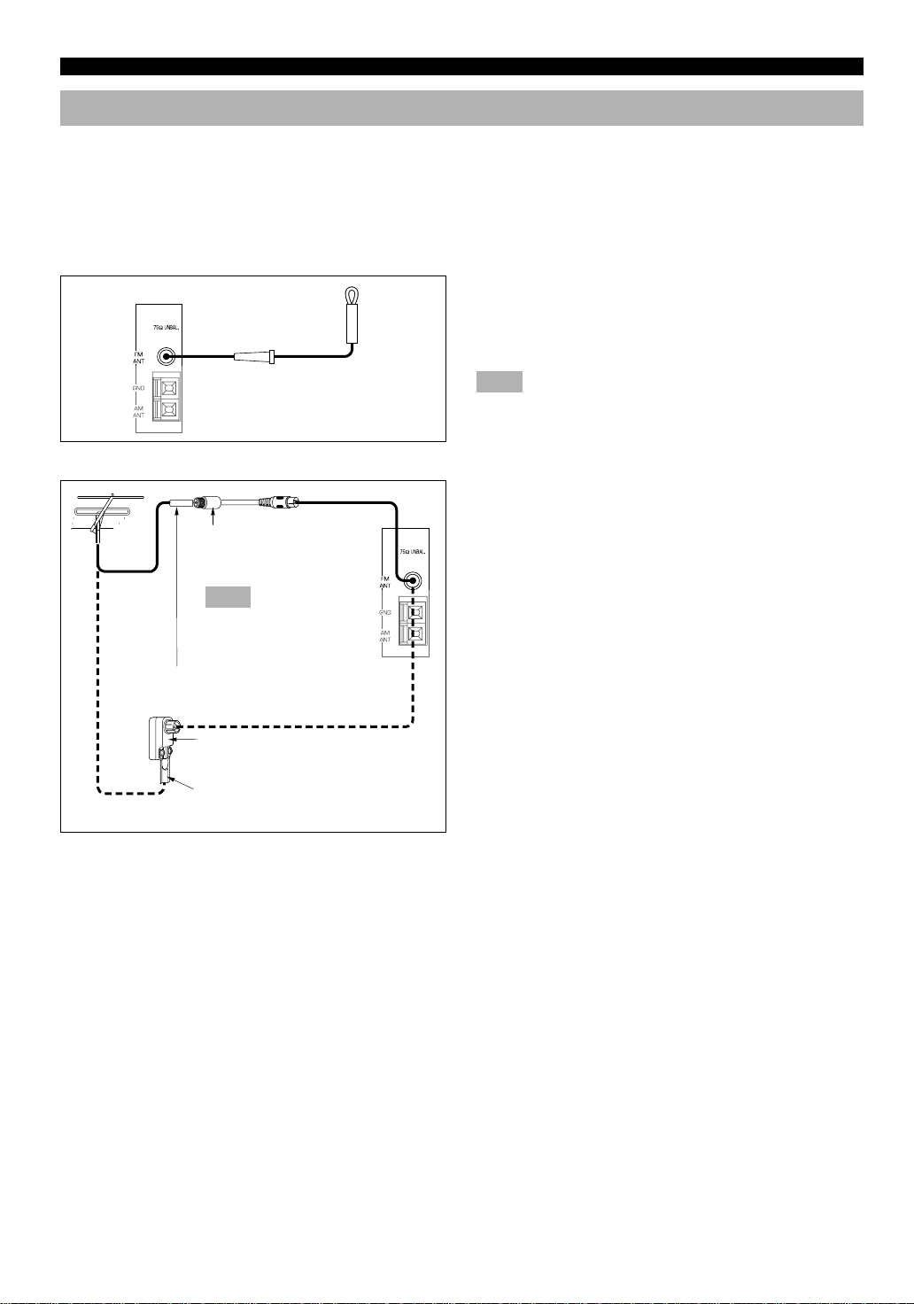
Connecting the Antennas
Both AM and FM indoor antennas are included with this unit. In general, these antennas should provide sufficient signal
strength. However, a properly installed outdoor antenna provides clearer reception than an indoor one. If you experience poor
reception quality, an outdoor antenna may improve the quality.
Connect each antenna correctly to the designated terminals.
■ Indoor FM antenna (included)
Firmly insert the connector into the FM ANT terminal. The
Indoor FM
antenna
■ Outdoor FM antenna
Antenna adapter
(included for U.S.A. and
Canada models)
Note
Use this adapter to match
with F-type connector
75-ohm coaxial cable
indoor FM antenna is only a simple antenna. For reception
with better sound quality, installing the outdoor FM antenna
(commercially available) is recommended.
Note
• Do not connect an outdoor FM antenna and the indoor FM
antenna at the same time.
You may be unable to obtain good FM radio reception
depending on your local conditions (distance from the
broadcasting station, interposing buildings and
mountains, etc.). Consult your dealer or authorized service
center and be sure to install an antenna that suits your local
conditions.
Install the outdoor FM antenna (commercially available) in
a high place as far away from any roads as possible to avoid
being affected by automobile ignition noise.
75-ohm/300-ohm antenna
adapter
300-ohm feeder
10
Page 15

■ AM loop antenna (included)
AM loop antenna
■ Connecting the AM loop antenna
CONNECTIONS
The AM loop antenna can be removed from the stand and
attached to a wall, etc. However, note that the reception
sensitivity may deteriorate if the antenna is attached to a
metal or steel reinforced wall.
Notes
• The AM loop antenna should be placed away from this unit.
• The AM loop antenna should always be connected, even if an
outdoor AM antenna is connected to this unit.
INTRODUCTION
1
3
2
Antenna stand
■ Outdoor AM antenna
Vinyl covered wire (5 m to 10 m)
■ Ground (GND terminal)
1 Press the tab and unlock the terminal hole.
2 Insert the AM loop antenna lead wires into the
AM ANT and GND terminals.
PREP ARA TION
3 Return the tab to its original position to lock
54
the lead wires. Lightly pull the lead wires to
confirm a good connection.
4 Attach the loop antenna to the antenna stand.
5 Orient the AM loop antenna so that the best
reception is obtained.
If you cannot obtain good reception with the AM loop
antenna, connect 5 m to 10 m of vinyl covered wire to the
AM ANT terminal and extend it outdoors from a window.
ADV ANCED OPERA
For maximum safety and minimum interference, connect
the antenna GND terminal to a good earth ground. A good
earth ground is a metal stake driven into moist earth.
TION APPENDIX
11
EnglishBASIC OPERATION
Page 16
CONNECTIONS
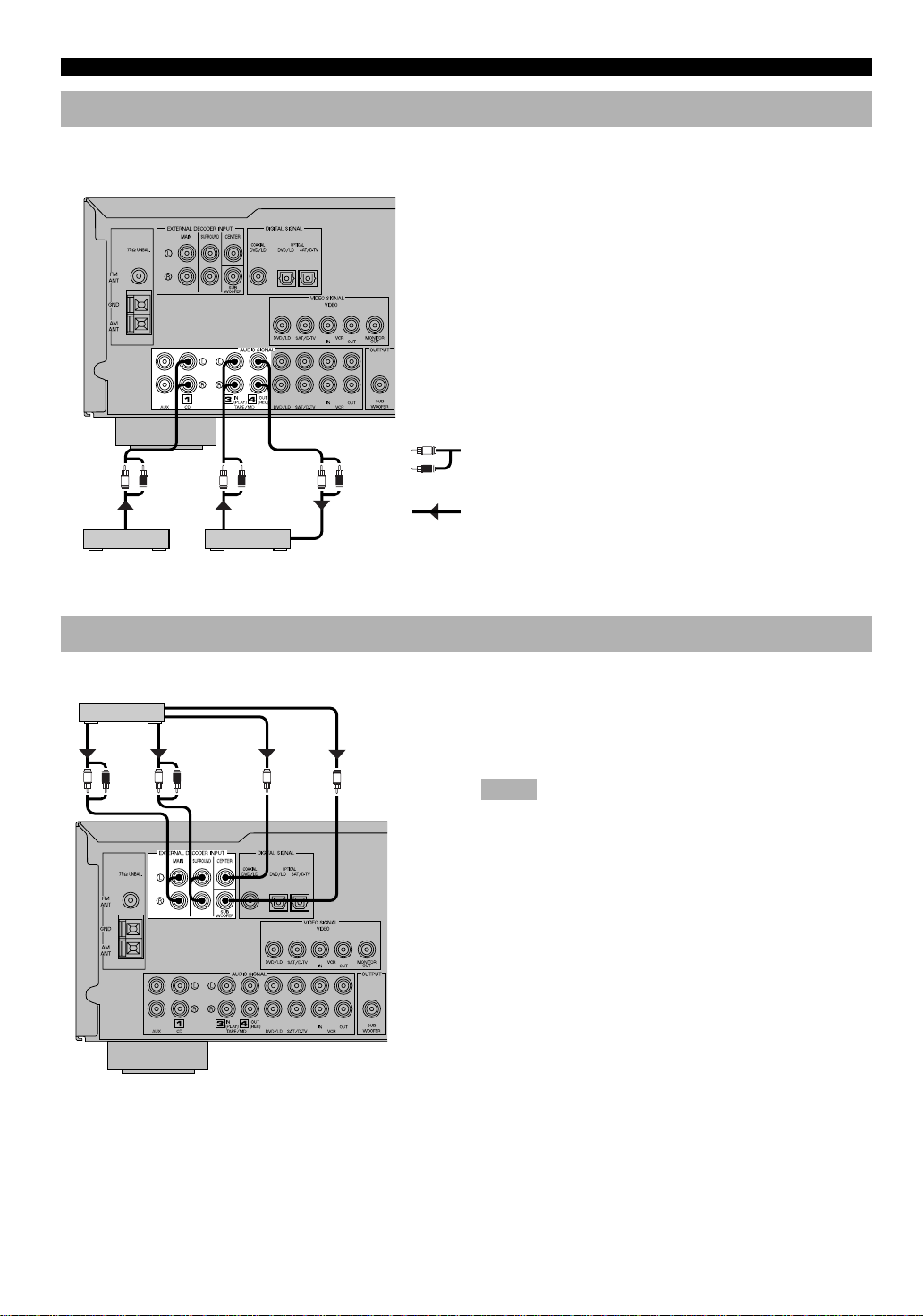
Connecting an Audio Component
(U.S.A. model)
L R L R L R
L
R
Be sure to connect the right channel (R), left channel (L),
input (IN) and output (OUT) properly.
Analog signal
OUTPUT LINE OUT LINE IN
CD player
Tape deck or
MD recorder
Connecting to an External Decoder
External decoder
MAIN
OUT
L R L R
SURROUND
OUT
CENTER
OUT
SUBWOOFER
OUT
(U.S.A.
model)
Signal flow
This unit has additional 6-channel audio signal input
terminals for connecting an external decoder to this unit.
Connect the 6-channel audio signal output terminals of the
decoder to the EXTERNAL DECODER INPUT terminals
of this unit.
Notes
• When a source connected to these terminals is selected, the digital
sound field processor cannot be used.
• The settings of “CENTER SP”, “REAR SP”, “MAIN SP” and
“BASS OUT” in the SET MENU have no effect on a source
connected to these terminals. The setting of “MAIN LVL” is
effective. (Refer to pages 32 and 33 for details.)
12
Page 17

Connecting a Video Component
DVD/LD player TV/digital TV, satellite tuner, cable TV
CONNECTIONS
ANALOG
AUDIO OUT
L R
VIDEO
OUT
V
COAXIAL
DIGITAL OUT
C
OPTICAL
DIGITAL OUT
(U.S.A. model)
L R
AUDIO
OUT
L R V V
AUDIO
IN
VIDEO
OUT
VCR
■ Audio signal terminals
Be sure to connect the right channel (R), left channel (L),
input (IN) and output (OUT) properly.
■ Video signal terminals
Be sure to connect the input (IN) and output (OUT)
properly.
■ Digital audio signal terminals
If your DVD/LD player, TV/digital TV or satellite
tuner, etc. has coaxial or optical digital signal output
terminals, they can be connected to this unit’s COAXIAL
and/or OPTICAL digital signal input terminals. To make a
connection between the optical digital signal terminals,
remove the cover from each terminal, and then connect
them by using a commercially available optical fiber cable
that conforms to EIA standards. Other cables might not
function correctly.
L
R
V
O
C
ANALOG
AUDIO OUT
L R
Analog signal
Video signal
Digital signal
(optical)
Digital signal
(coaxial)
VIDEO
IN
OPTICAL
DIGITAL OUT
OO
VIDEO
OUT
V
V
VIDEO
IN
Signal flow
TV monitor
Notes
• Be sure to attach the covers when the OPTICAL terminals are not
being used in order to protect them from dust.
• If your LD player has a Dolby Digital RF signal output terminal,
be sure to use the RF demodulator (separately purchased).
• No sound will be heard when connecting your LD player’s Dolby
Digital RF signal output terminal directly to this unit’s COAXIAL
DVD/LD digital signal input terminal.
y
• The input signal from the DVD/LD input terminals is selected in
the following order of priority with the input mode set to AUTO:
COAXIAL terminal → OPTICAL terminal → Analog terminal.
Refer to page 21 for details.
• All digital signal input terminals are applicable to sampling
frequencies of 32 kHz, 44.1 kHz and 48 kHz.
INTRODUCTION
PREP ARA TION
ADV ANCED OPERA
TION APPENDIX
When making connections between the digital signal
terminals, you should connect the components to the samenamed analog audio signal terminals of this unit, because a
digital signal cannot be recorded by a tape deck, MD
recorder or VCR connected to this unit.
EnglishBASIC OPERATION
13
Page 18

CONNECTIONS
Connecting Speakers
Right Left
Subwoofer connection
If you have a subwoofer with builtin amplifier, including the
YAMAHA Active Servo Processing
Subwoofer System, connect the
input terminal of the subwoofer
system to the SUBWOOFER
OUTPUT terminal of this unit.
Main speakers A
Main speakers B
Right Left
(U.S.A. model)
L
MAIN
––++
R
A
B
+
–
SET BEFORE POWER ON
MAIN A OR B:4ΩMIN. /SPEAKER
A + B:8ΩMIN. /SPEAKER
CENTER : 6ΩMIN. /SPEAKER
REAR : 6ΩMIN. /SPEAKER
MAIN A OR B:8ΩMIN. /SPEAKER
A + B:I6ΩMIN. /SPEAKER
CENTER : 8ΩMIN. /SPEAKER
REAR : 8ΩMIN. /SPEAKER
REAR
L
R
CENTER
(SURROUND)
+
–
MAINS
120 V 60Hz
100W MAX. TOTAL
SWITCHED
Center speaker Rear speakers
Be sure to connect the right channel (R), left channel (L),
“+” (red) and “–” (black) properly. If the connections are
faulty, no sound will be heard from the speakers, and if the
polarity of the speaker connections is incorrect, the sound
will be unnatural and lack bass.
CAUTIONS
• Use speakers with the specified impedance shown on
the rear panel of this unit.
• Do not let the bare speaker wires touch each other and
do not let them touch any metal part of this unit. This
could damage the unit and/or speakers.
Right Left
■ Main speaker terminals
One or two speaker systems can be connected to these
terminals. If you use only one speaker system, connect it to
either of the SPEAKERS A or B terminals.
■ Rear speaker terminals
A rear speaker system can be connected to these terminals.
■ Center speaker terminal
A center speaker can be connected to this terminal.
14
Page 19
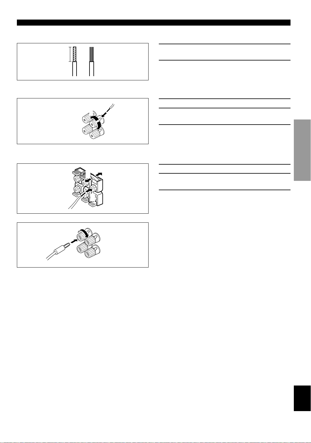
■ Speaker cables
CONNECTIONS
10 mm (3/8”)
from each of the speaker cable.
2 Twist the exposed wires of the cable together
to prevent short circuits.
■ Connecting to the MAIN SPEAKERS terminals
1 Remove approx. 10 mm (3/8”) of insulation
Red: positive (+)
Black: negative (–)
2
1
3
■ Connecting to the REAR and CENTER SPEAKERS terminals
Red: positive (+)
Black: negative (–)
1
3
2
1 Unscrew the knob.
2 Insert one bare wire into the hole in the side of
each terminal.
3 Tighten the knob to secure the wire.
1 Open the tab.
2 Insert one bare wire into the hole of each
terminal.
3 Return the tab to secure the wire.
INTRODUCTION
PREP ARA TION
y
Banana plug connections are also possible. Simply insert the
banana plug connector into the corresponding terminal.
ADV ANCED OPERA
TION APPENDIX
EnglishBASIC OPERATION
15
Page 20
CONNECTIONS
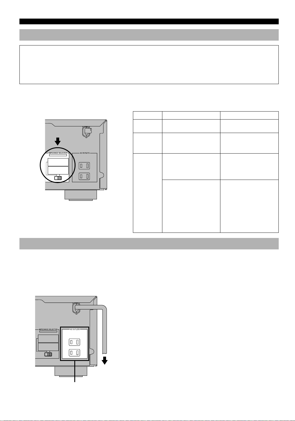
IMPEDANCE SELECTOR Switch
WARNING
Do not change the IMPEDANCE SELECTOR switch setting while the power to this unit is on, otherwise the unit may be
damaged.
If this unit fails to turn on when STANDBY/ON is pressed, the IMPEDANCE SELECTOR switch may not be fully slide
to either position. If so, slide the switch to either position fully when this unit is in the standby mode.
Select the right or left position according to the impedance of speakers in your system. Be sure to move this switch only
when this unit is in the standby mode.
(U.S.A. model)
If you use left position right position
Center
IMPEDANCE
SELECTOR
MAINS
speaker
Rear
speakers
SET BEFORE POWER ON
MAIN A OR B:4ΩMIN. /SPEAKER
A + B:8ΩMIN. /SPEAKER
CENTER : 6ΩMIN. /SPEAKER
REAR : 6ΩMIN. /SPEAKER
MAIN A OR B:8ΩMIN. /SPEAKER
A + B:I6ΩMIN. /SPEAKER
CENTER : 8ΩMIN. /SPEAKER
REAR : 8ΩMIN. /SPEAKER
120 V 60Hz
100W MAX. TOTAL
SWITCHED
Main
speakers
Connecting the Power Supply Cords
The impedance must be 6 Ω
or higher.
The impedance of each
speaker must be 6 Ω or
higher.
If you use one pair of main
speakers, the impedance of
each speaker must be 4 Ω or
higher.
If you use two pairs of main
speakers, the impedance of
each speaker must be 8 Ω or
higher.
The impedance must be 8 Ω
or higher.
The impedance of each
speaker must be 8 Ω or
higher.
If you use one pair of main
speakers, the impedance of
each speaker must be 8 Ω or
higher.
If you use two pairs of main
speakers, the impedance of
each speaker must be 16 Ω or
higher.
[Canada model only]
The impedance of each
speaker must be 8 Ω or
higher.
After completing all connections, connect the AC power
cord to an AC power outlet. Disconnect the AC power cord
if you will not use this unit for a long period of time.
■ AC OUTLETS (SWITCHED)
(U.S.A. model)
MAINS
SET BEFORE POWER ON
MAIN A OR B:4ΩMIN. /SPEAKER
A + B:8ΩMIN. /SPEAKER
CENTER : 6ΩMIN. /SPEAKER
REAR : 6ΩMIN. /SPEAKER
MAIN A OR B:8ΩMIN. /SPEAKER
A + B:I6ΩMIN. /SPEAKER
CENTER : 8ΩMIN. /SPEAKER
REAR : 8ΩMIN. /SPEAKER
120 V 60Hz
100W MAX. TOTAL
SWITCHED
To AC outlet
SWITCHED
16
U.S.A. and Canada models ..............................2 OUTLETS
Australia model .................................................. 1 OUTLET
Use these outlets to connect the power cords from your
components to this unit. The power to the AC OUTLET(S)
is controlled by this unit’s STANDBY/ON (or POWER).
These outlets will supply power to any connected
component whenever this unit is turned on. The maximum
power (total power consumption of components) that can be
connected to the AC OUTLET(S) is 100 W.
Page 21

ADJUSTING THE SPEAKER BALANCE
1
2,7
6
3
5
TEST
LEFT
TEST
RIGHT
TEST L SUR. TEST R SUR.
TEST CENTER
This procedure lets you adjust the sound output level
balance between the main, center and rear speakers by using
the built-in test tone generator. When this adjustment is
performed, the sound output level heard at the listening
position will be the same from each speaker. This is
important for the best performance of the digital sound field
processor, the Dolby Pro Logic decoder and Dolby Digital
decoder.
Before You Start Adjusting
12
LR
–+–+
3
4
1 Set VOLUME to the “m”
position.
Using the Test Tone
The adjustment of each speaker sound output level should
be performed at your listening position with the remote
control. After completing the adjustments, use VOLUME
(u/d) at your listening position to check if the adjustments
are satisfactory.
1 Press AMP(TUNER) on the
component selector.
2 Press TEST .
“TEST LEFT” appears on the display.
INTRODUCTION
PREP ARA TION
2 Turn the power on.
3 Press SPEAKERS A or B
to select the main
speakers to be used.
If you use two main speaker
systems, press both A and B.
4 Set BASS, TREBLE and BALANCE to the “0”
position.
LR
–+–+
3 Turn up the volume.
You will hear a test tone (like pink noise) from each
speaker for about two seconds in following order: left
main speaker, center speaker, right main speaker, right
rear speaker and left rear speaker. The display changes
as shown below.
Notes
• If the test tone cannot be heard, turn down the volume, set the unit
in the standby mode and check the speaker connections.
• If the test tone cannot be heard from the center speaker, check the
setting of “CENTER SP” in the SET MENU.
ADV ANCED OPERA
TION APPENDIX
EnglishBASIC OPERATION
17
Page 22
ADJUSTING THE SPEAKER BALANCE
4 Adjust BALANCE on the
front panel so that the
sound output level of the
right main speaker and the
left main speaker is the
same.
LR
Front panel
5 Press TIME/LEVEL
repeatedly to select the
speaker to be adjusted.
“CENTER”, “R SUR.” or
“L SUR.” appears on the
display.
6 Press + to raise and – to
lower the level. Adjust the
sound output levels of the
center speaker and the
rear speakers so that they
become almost the same
as that of the main
speakers.
While adjusting, the test tone is
heard from the selected speaker.
Note
• You cannot adjust the delay time while the test tone is being heard
even if “DELAY” appears on the display.
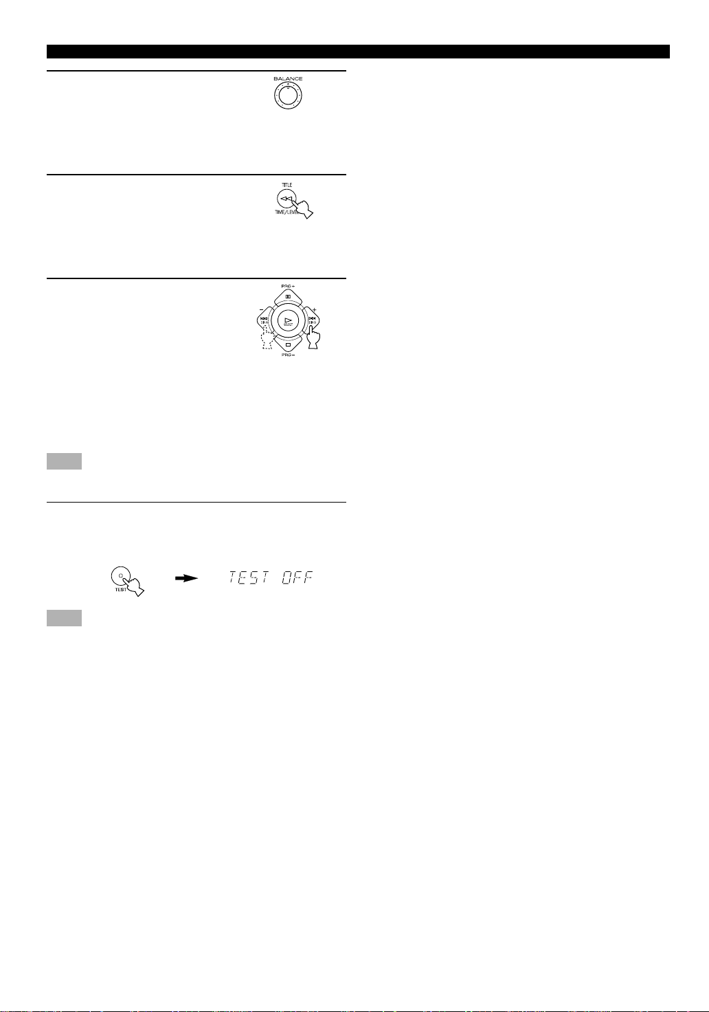
7 When the adjustment is complete, press TEST.
“TEST OFF” appears on the display and the test tone
stops.
Note
• If “CENTER SP” in the SET MENU is set to the NONE position,
the sound output level of the center speaker cannot be adjusted in
step 6. The center channel sound is automatically output from the
right and left main speakers.
y
• Once you have completed the adjustments, you can only adjust
the overall volume level of your audio system by using VOLUME
(or VOLUME (u/d)).
• If there is insufficient sound output from the center and rear
speakers, you may decrease the main speaker output level by
setting “MAIN LVL” in the SET MENU to “–10 dB”. (Refer to
page 33 for details.)
18
Page 23
BASIC OPERATION
PLAYING A SOURCE
When using the remote control, press AMP(TUNER) on
the component selector.
2
LR
–+–+
3
67
4
6
2
7
4
1 Set VOLUME to the “m”
position.
Front panel
2 Turn the power on.
or
Front panel Remote control
3 Press SPEAKERS A or B
to select the main
speakers to be used.
If you use two main speaker
systems, press both A and B.
Front panel
1,6
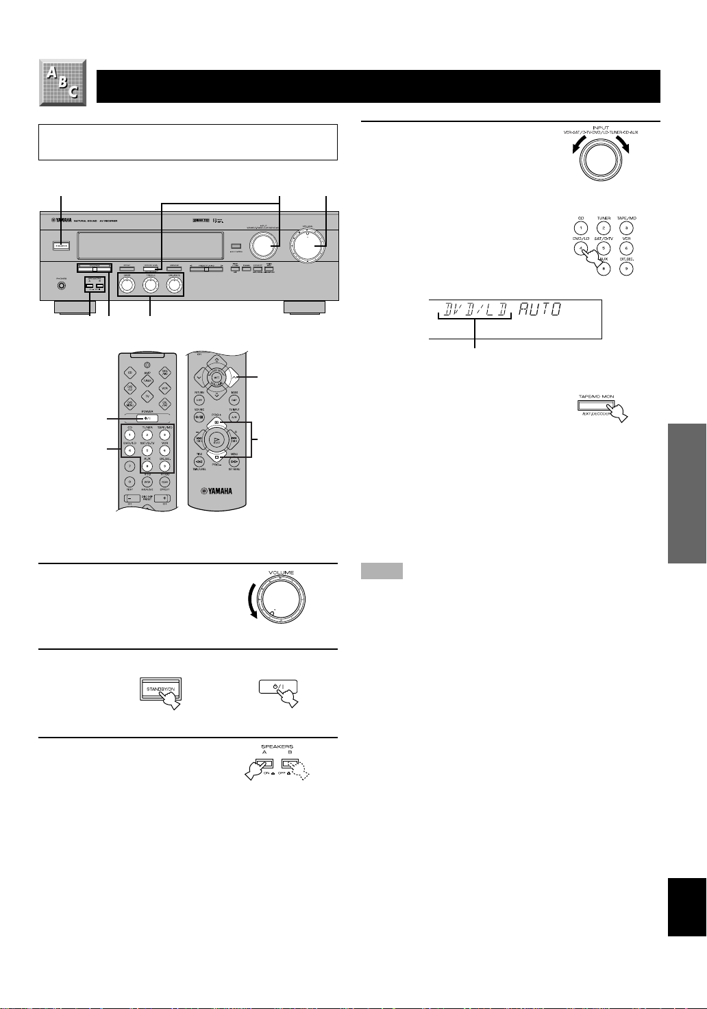
4 Select the desired input
source with INPUT (or the
input selector buttons).
(Turn on the TV monitor for
video sources.)
The name of the selected input
source appears on the display.
Input source
a. To select a tape or an MD source
Press TAPE/MD MON / EXT.
DECODER (or TAPE/MD) so
that the “TAPE/MD
MONITOR” indicator lights up
on the display.
b. To select a source connected to the
EXTERNAL DECODER INPUT terminals
Press TAPE/MD MON / EXT. DECODER repeatedly
(or EXT. DEC.) until “EXT. DECODER” appears on
the display.
Notes
• An audio source can not be played if the “TAPE/MD MONITOR”
indicator lights up or if “EXT. DECODER” appears. Press TAPE/
MD MON / EXT. DECODER twice (or TAPE/MD once) to turn
off the “TAPE/MD MONITOR” indicator. Press TAPE/MD
MON / EXT. DECODER once (or EXT. DEC.) to turn off “EXT.
DECODER”.
• If you select and play a video source when the “TAPE/MD
MONITOR” indicator lights up or “EXT. DECODER” appears,
the play back result will be a video image from the video source
and the sound from the audio source selected by using TAPE/MD
MON / EXT. DECODER (or TAPE/MD or EXT. DEC.).
y
For the DVD/LD, TV/digital TV and satellite tuner sources, the
current input mode is also shown. Refer to page 21 for details about
the input mode.
Front panel
or
Remote control
Front panel
ADV ANCED OPERA
TION APPENDIXINTRODUCTION PREP ARA TION
19
EnglishBASIC OPERATION
Page 24

PLAYING A SOURCE
5 Play the source.
Refer to the instructions for the source component (and
page 26 for details about tuning).
Note
• When controlling an audio/video component (tape deck, MD
recorder, CD player, DVD/LD player, etc.) with the remote
control, press one of the component selector buttons, (TAPE/MD,
CD, DVD/LD, etc.), which corresponds to the component you
want to control. Refer to “PRESET REMOTE CONTROL” on
page 38.
6 Adjust the volume to the desired output level.
If desired, adjust BASS, TREBLE, BALANCE, etc.
These controls are only effective for the sound from the
main speakers.
• BASS controls the low-frequency response.
• TREBLE controls the high-frequency response.
• BALANCE adjusts the balance of the output volume
from the right and left main speakers.
or
Front panel Remote control
■ To mute the sound
Press MUTE on the remote
control.
To cancel mute, press MUTE.
Note
• During muting, “MUTE ON” appears on the display.
■ When you have finished using this
unit
Press STANDBY/ON (or POWER) to set this unit in the
standby mode.
■ BGV (background video) function
The BGV function allows you to combine a video image
from a video source with a sound from an audio source.
(For example, you can listen to classical music while you
are watching a video.) This function can only be controlled
with the remote control.
Play a video source, and then select an audio source with
the input selector buttons on the remote control. The BGV
function does not work if you select the audio source with
INPUT on the front panel.
LR
–+–+
Front panel
7 Use the digital sound field processor.
Refer to page 22.
or
Front panel Remote control
20
Page 25

PLAYING A SOURCE
Input Mode (for the DVD/LD and TV/
digital TV and satellite tuner
sources)
This unit allows you to switch the input mode for sources
that send both digital and analog signals to this unit. The
AUTO and ANALOG input modes are provided.
When you turn on the power of this unit, the input mode for
the DVD/LD source is always set to AUTO and for TV/
digital TV or satellite tuner source is set according to “SAT
INPUT” in the SET MENU. (Refer to page 34 for details.)
■ AUTO
In this mode, the input signal is selected in the following
order of priority:
1. Digital signal encoded with Dolby Digital
2. Normal digital signal (PCM)
3. Analog signal (ANALOG)
Note
• If digital signals are input from both the OPTICAL and
COAXIAL terminals, the digital signal from the COAXIAL
terminal is selected.
■ ANALOG
In this mode, only an analog signal is selected, even if a
digital signal is being input at the same time. Select this
mode when you want to use an analog signal instead of a
digital signal.
■ Switching the input mode
Press INPUT MODE (or the input selector
button that you have pressed to select the
input source on the remote control) repeatedly
until the desired input mode is shown on the
display.
or
Front panel Remote control
Notes
• Set the input mode to AUTO to play a DVD/LD source encoded
with Dolby Digital.
• Set the input mode to ANALOG to play a normal 2-channel
source with a Dolby Surround program.
• The sound output may be interrupted for some LD and DVD
players in the following situation: The input mode is set to
AUTO. A search is performed while playing the disc encoded
with Dolby Digital, and then disc playing is restored. The sound
output is interrupted for a moment because the digital signal was
selected again.
• The input mode cannot be changed for the CD, TUNER, TAPE/
MD, VCR and AUX sources because only analog signals are used
for these.
• The current input mode appears on the display when the DVD/
LD, TV/digital TV or satellite tuner source is selected or the input
mode is changed.
ADV ANCED OPERA
■ Notes on playing an LD source
• Some audio/video component, such as LD player, output different
audio signals through their analog and digital terminals. Change
the input mode as necessary.
• If the input mode is set to AUTO for the LD source, this unit
automatically determines which type of signal the LD source
contains. If this unit detects a Dolby Digital signal, the decoder
automatically switches to the appropriate setting and reproduces
5.1 channel sound.
• If the LD player is transmitting signals by a non-normal method,
this unit cannot detect the Dolby Digital signal. In this case, the
decoder automatically switches to PCM or analog.
• If the LD source does not contain a digital soundtrack, connect
the LD player to the analog terminals.
• While you are operating the LD player, if you switch from the
pause or chapter forwarding function to normal playback, you
may hear the PCM or analog sound an instant before the Dolby
Digital sound is played.
21
TION APPENDIXINTRODUCTION PREP ARA TION
EnglishBASIC OPERATION
Page 26

DIGITAL SOUND FIELD PROCESSOR (DSP) EFFECT
Selecting a DSP Program
You can enhance your listening experience by selecting a
DSP program. Refer to pages 23 to 25 for details about each
program.
LR
–+–+
2
2
3
■ On the front panel
1 Make sure that the effect speakers (center,
rear, and subwoofer) are turned on.
2 Press PROGRAM h or l repeatedly to select
the desired program.
The name of the selected
program appears for a moment
and the selected DSP program
indicator lights up on the
display.
DSP program indicator
■ On the remote control
1 Make sure that the effect speakers (center,
rear, and subwoofer) are turned on.
2 Press AMP(TUNER) on the
component selector.
3 Press PRG+ or PRG–
repeatedly to select the
desired program.
The name of the selected
program appears for a moment
and the selected DSP program
indicator lights up on the
display.
DSP program indicator
y
If desired, adjust the delay time and the sound output level of each
speaker. (Refer to pages 35 and 36 for details.)
Notes
• You can select a DSP program for each of the input sources. Once
you select a program, it is linked with the input source selected at
that time. So, when you select the input source next time, the
same program is automatically selected.
• When a monaural source is being played with PRO LOGIC/
Normal or PRO LOGIC/ENHANCED, no sound will be heard
from the main speakers and the rear speakers. Sound can only be
heard from the center speaker. However, if “CENTER SP” in the
SET MENU is set to the NONE position, the center channel
sound is output from the main speakers.
• When a source connected to the EXTERNAL DECODER INPUT
terminals of this unit is selected, the digital sound field processor
cannot be used.
Canceling the Sound Effect (turning
off the effect speakers)
Press EFFECT to cancel
the sound effect and
monitor only the main
sound.
Press EFFECT again to turn the
sound effect back on.
Notes
• If the sound effect is canceled when Dolby Digital is decoding,
the sounds of all channels are mixed and output from the main
speakers.
• If you turn off the sound effect when Dolby Digital is decoding, it
may happen that the sound is output faintly or not output
normally, depending on the source. In that case, turn back on the
sound effect.
Front panel
or
Remote control
22
Page 27

SOUND FIELD PROGRAM
This unit incorporates a sophisticated, multi-program digital sound field processor (DSP). This processor allows you to
electronically expand and change the shape of the audio sound field from both audio and video sources, creating a theaterlike experience in your listening room. You can create outstanding audio sound by selecting a suitable DSP program (this
will, of course, depend on what you are listening to).
When you select a CINEMA DSP program, one of the built-in decoders (Dobly Pro Logic and Dolby Digital) is turned on
according to which type of signals the source being played contains.
The following list gives you a brief description of the sound fields produced by each of the DSP programs. Keep in mind that
most of these are precise digital re-creations of actual acoustic environments.
■ For movie or audio/video sources (Program No. 1 to No. 5: CINEMA DSP
programs)
No. PROGRAM SUBPROGRAM FEATURES
1 q SURROUND [1] PRO LOGIC/Normal ( o )
• Input source: Dolby Surround
2-ch Dolby Digital
• Output channel: 4 channels
• DSP: —
[2] DOLBY DIGITAL/Normal ( g )
• Input source: Dolby Digital
• Output channel: 5.1 channels
• DSP: —
[3] PRO LOGIC/ENHANCED
( ox)
• Input source: Dolby Surround
2-ch Dolby Digital
• Output channel: 4 channels
• DSP: 1 (surround)
[4] DOLBY DIGITAL/ENHANCED
( gx )
• Input source: Dolby Digital
• Output channel: 5.1 channels
• DSP: 2 (surround L, R)
The built-in Dolby Pro Logic decoder or
Dolby Digital decoder precisely reproduces
the sound and effect of a source encoded with
Dolby Surround or Dolby Digital.
The realization of a highly efficient decoding
process improves cross talk and channel
separation, and makes sound positioning
smoother and more precise.
In this program, the digital sound field
processor is not turned on.
This program ideally simulates the multisurround speaker systems of the 35 mm-film
movie theater. Dolby Pro Logic decoding or
Dolby Digital decoding and digital sound
field processing are precisely performed
without altering the original sound
orientation.
The surround effect produced by the sound
field folds around the viewer naturally from
the rear to the right and left and toward the
screen.
ADV ANCED OPERA
23
TION APPENDIXINTRODUCTION PREP ARA TION
EnglishBASIC OPERATION
Page 28

SOUND FIELD PROGRAM
No. PROGRAM SUBPROGRAM FEATURES
2 MOVIE
THEATER1
[1] 70 mm SPECTACLE
( ox)
• Input source: Dolby Surround
2-ch Dolby Digital
• Output channel: 3 channels
• DSP: 2 (presence & surround)
[2] DGTL SPECTACLE
( g x )
• Input source: Dolby Digital
• Output channel: 5.1 channels
• DSP: 3 (presence & surround L, R)
This program creates the extremely wide sound
field of a movie theater. It precisely reproduces
the source sound in detail, giving both the video
and the sound field incredible reality. It is ideal
for any kind of video source encoded with
Dolby Surround or Dolby Digital (especially
large-scale movie productions).
3 MOVIE
THEATER2
[3] 70 mm SCI-FI ( o x )
• Input source: Dolby Surround
2-ch Dolby Digital
• Output channel: 3 channels
• DSP: 2 (presence & surround)
[4] DGTL SCI-FI ( g x )
• Input source: Dolby Digital
• Output channel: 5.1 channels
• DSP: 3 (presence & surround L, R)
[1] 70 mm ADVENTURE
( ox )
• Input source: Dolby Surround
2-ch Dolby Digital
• Output channel: 3 channels
• DSP: 2 (presence & surround)
[2] DGTL ADVENTURE
( gx)
• Input source: Dolby Digital
• Output channel: 5.1 channels
• DSP: 3 (presence & surround L, R)
[3] 70 mm GENERAL ( ox )
• Input source: Dolby Surround
2-ch Dolby Digital
• Output channel: 3 channels
• DSP: 2 (presence & surround)
[4] DGTL GENERAL ( gx )
• Input source: Dolby Digital
• Output channel: 5.1 channels
• DSP: 3 (presence & surround L, R)
Clearly reproduces dialog and sound effects in
the latest sound form of science fiction films,
thus creating a broad and expansive cinematic
space amid the silence. You can enjoy science
fiction films in a virtual-space sound field that
includes Dolby Surround and Dolby Digitalencoded software employing the most advanced
techniques.
Ideal for precisely reproducing the sound of the
newest multi-track films. The sound field is
made to be similar to that of the newest movie
theaters, so the reverberations of the sound field
itself are restrained as much as possible. The
data for the sound field of an opera house are
used for the front presence, so the threedimensional feeling of the sound field is
emphasized, and dialog is precisely oriented on
the screen. By using the data for the sound field
of a concert hall on the surround sound field,
powerful reverberations are generated. You can
enjoy watching action, adventure movies, etc.
with strong presence.
This program is for reproducing sounds on a
multi-track film, and is characterized by a soft
and extensive sound field. The front presence of
the sound field is relatively narrow. It spatially
spreads all around and toward the screen,
restraining echo effect of conversations without
losing clarity. For the surround sound field, the
harmony of music or chorus sounds beautifully
in a wide space at the rear of the sound field.
24
Page 29
No. PROGRAM FEA TURES
4 MONO MOVIE
• Input source: Monaural
• Output channel: 1 channel
• DSP: 1
5 TV SPORTS
• Input source: Audio/Video
• Output channel: 2 to 5.1 channels
• DSP: 2 to 3 (presence & surround)
This program is designed specifically to enhance monaural
sources. Compared to a strictly mono setting, the sound image
is wider and slightly forward of the speaker pair, lending an
immediacy to the overall sound. It is particularly effective for
old mono movie, news broadcasts and dialog.
This program is furnished with a tight sound field in which the
sound will not spread excessively at the front, but the rear
surround produces dynamic sound expansion. It is the most
suitable for sports programs.
■ For Hi-Fi audio sources
No. PROGRAM FEATURES
6 DISCO
• Input source: 2-ch PCM/Analog audio
• Output channel: 2 channels
• DSP: 1
This program simulates the acoustic environment of a disco in
the heart of a lively city. The sound is dense and highly
concentrated.
SOUND FIELD PROGRAM
7 ROCK CONCERT
• Input source: 2-ch PCM/Analog audio
• Output channel: 2 channels
• DSP: 1
8 CONCERT HALL
• Input source: 2-ch PCM/Analog audio
• Output channel: 2 channels
• DSP: 1
This program is ideally suited for rock music. You will
experience a dynamic and lively sound field.
This program creates the expansive ambience of a large concert
hall. It is suited for orchestra and opera music.
CINEMA DSP: Dolby Surround + DSP/Dolby Digital + DSP
■ Dolby Pro Logic + 2 digital sound fields
Digital sound fields are created in both the presence and
rear surround zones of the Dolby Pro Logic-decoded sound
field. They create a wide acoustic environment and
emphasize the surround effect in the room, letting you feel
as much presence as if you were watching a movie in a
popular Dolby Stereo theater.
■ Dolby Digital + 3 digital sound fields
Digital sound fields are created in the presence zone and
independently on the left and right surround zones of the
Dolby Digital-decoded sound field. They create a wide
acoustic environment and strong surround effect in the room
without losing high channel separation. With the wide
dynamic range of Dolby Digital sound, this sound field
combination lets you feel as if you were watching a movie
in the newest Dolby Digital theater. This is the most ideal
home theater sound at the present time.
ADV ANCED OPERA
TION APPENDIXINTRODUCTION PREP ARA TION
EnglishBASIC OPERATION
25
Page 30

TUNING
Automatic tuning is effective when station signals are
strong and there is no interference. However, if the signal
from the station you want to select is weak, you must tune
in to it manually (manual tuning).
1
LR
–+–+
5
32
4
Automatic Tuning
1 Use INPUT to select the
tuner as the input source.
2 Press FM/AM to select the reception band (FM
or AM).
“FM” or “AM” appears on the display.
or
5 Press PRESET/TUNING h once to tune in to a
higher frequency and l once to tune in to a
lower frequency.
Press the button again if the tuning search does not stop
at the desired station.
Note
• If you tune in manually to an FM station, it will be automatically
received in monaural mode to increase the signal quality.
y
• Use the manual tuning method if the tuning search does not stop
at the desired station (because the signal from the station is weak).
• When tuned in to a station, the frequency of the received station is
shown on the display.
Manual Tuning
1 Use INPUT to select the
tuner as the input source.
2 Press FM/AM to select the reception band (FM
or AM).
“FM” or “AM” appears on the display.
3 Press TUNING MODE so that the “AUTO”
indicator lights up on the display.
Lights up
4 Press PRESET/TUNING (EDIT) to turn “ z ” off.
Turn “ z ” off
or
3 Press TUNING MODE so that the “AUTO”
indicator goes off.
Goes off
4 Press PRESET/TUNING (EDIT) to turn “ z ” off.
Turn “ z ” off
5 Press PRESET/TUNING h or l to tune in to
the desired station.
To continue the tuning search, hold down the button.
26
Page 31

TUNING
Automatic Preset Tuning (for FM
stations only)
You can make use of the automatic preset tuning function
for FM stations only. This function enables the unit to
automatically tune in with strong signals and to sequentially
store up to 40 FM stations (5 groups x 8 stations).
LR
–+–+
21 3
1 Press FM/AM to select the FM band.
2 Press TUNING MODE so that the “AUTO”
indicator lights up on the display.
Lights up
3 Hold down MEMORY for about three seconds.
The preset number, the “MEMORY” and “AUTO”
indicators flash. After about five seconds, automatic
preset tuning begins from the frequency currently
displayed toward the higher frequencies.
Received stations are sequentially stored as A1, A2 ...
A8. If more than 8 stations have been tuned, they are
stored as preset station numbers in other groups (B, C,
D and E) in that order.
■ Automatic preset tuning options
You can select the preset number from which the unit will
store FM stations and/or begin tuning toward lower
frequencies. Before automatic preset tuning begins (after
pressing MEMORY in step 3),
1. Press A/B/C/D/E and PRESET/TUNING to select the
preset number with which the first station will be stored.
The automatic preset tuning will stop when stations have
all been stored up to E8.
2. Press PRESET/TUNING (EDIT) to turn “ z ” off and
then press PRESET/TUNING l to begin tuning toward
lower frequencies.
■ When automatic preset tuning is
completed
The display shows the frequency of the last preset station.
Check the contents and the number of preset stations by
following the procedure in the section “To Recall a Preset
Station” on page 28.
Notes
• A new setting can be stored in place of the former one.
• You can manually replace a preset station with another FM or AM
station by simply using the manual preset tuning method.
• Even if the number of received stations is not enough to be stored
up to E8, automatic preset tuning is automatically ended after
searching for all stations.
• Only FM stations with sufficient signal strength are stored by
automatic preset tuning. If the station you want to store is weak in
signal strength, tune in to it manually in monaural mode and store
it by using the manual preset tuning method.
ADV ANCED OPERA
TION APPENDIXINTRODUCTION PREP ARA TION
Flashes
Memory back-up
The memory back-up circuit prevents the stored data
from being lost when this unit is set in the standby mode.
If, however, the power cord is disconnected from the AC
power outlet or the power is cut for more than one week,
the memory will be erased. If so, store the stations again
by using preset tuning methods.
EnglishBASIC OPERATION
27
Page 32

TUNING
Manual Preset Tuning
You can also store up to 40 stations (5 groups x 8 stations)
manually.
LR
–+–+
3 2,54
1 Tune in to the desired station.
Refer to page 26 for the tuning procedure.
2 Press MEMORY.
The “MEMORY” indicator flashes for about five
seconds.
Flashes
3 Press A/B/C/D/E repeatedly to select the
desired group (A to E) of preset stations
before the “MEMORY” indicator goes off.
Make sure that “ z ” appears on the display. The
selected group appears on the display.
To Recall a Preset Station
You can recall any desired station simply by selecting the
preset station number with which it was stored.
You can also recall a preset station with the remote control.
Press AMP(TUNER) on the component selector and press
TUNER on the input selector.
LR
–+–+
1 2
1
2
1 Press A/B/C/D/E to select the required group
of preset stations.
Make sure that “ z ” appears on the display.
4 Press PRESET/TUNING h or l to select a
preset station number (1 to 8) with which you
want to store the station before the “MEMORY”
indicator goes off.
Press h to select a higher
preset station number and l to
select a lower preset station
number.
5 Press MEMORY before the “MEMORY”
indicator goes off.
The displayed station has been stored as the preset
group and number you have selected, and the reception
band and frequency appear on the display.
6 Repeat steps 1 to 5 to store other stations.
Notes
• A new setting can be stored in place of the former one.
• The reception mode (stereo or monaural) is stored along with the
station frequency.
28
or
Front panel
Remote control
2 Press PRESET/TUNING h or l (or PRESET
+/–) to select a preset station number (1 to 8).
The preset group and number appear on the display
along with the reception band, frequency and signal
strength information.
or
Front panel
Remote control
Page 33

Exchanging Preset Stations
You can exchange the assignment of two preset stations
with each other.
■ Example: If you want to exchange
preset station “E1” with “A5”.
2,4
LR
–+–+
1 Recall preset station “E1”.
Refer to the procedure in the section “To Recall a
Preset Station” on page 28.
2 Hold down (PRESET/TUNING) EDIT for about
three second.
“E1” and the “MEMORY” indicator flash.
TUNING
Flashes
3 Recall preset station “A5” by using the buttons
on the front panel.
“A5” and the “MEMORY”
indicator flash.
Flashes
4 Press (PRESET/TUNING) EDIT again.
The display shows the exchange of stations has been
completed.
ADV ANCED OPERA
TION APPENDIXINTRODUCTION PREP ARA TION
EnglishBASIC OPERATION
29
Page 34

RECORDING A SOURCE ON TAPE, MD OR VIDEO CASSETTE
Recording adjustments and other operations are performed
from the tape deck, MD recorder or VCR. Refer to the
instructions for these components.
1,42
LR
–+–+
4
2
1 Set VOLUME to the “m”
position.
y
If a tape deck or MD recorder is being used for recording, you can
monitor the sounds being recorded by pressing TAPE/MD MON /
EXT. DECODER (or TAPE/MD).
Notes
• The DSP program and the setting of VOLUME, BASS, TREBLE
and BALANCE have no effect on the material being recorded.
• A source connected to this unit only through the digital terminals
cannot be recorded by the tape deck, MD recorder or VCR
connected to this unit.
• A source connected to the EXTERNAL DECODER INPUT
terminals of this unit cannot be recorded.
• Check the copyright laws in your country to record from records,
CDs, radio, etc. Recording of copyrighted material may infringe
copyright laws.
If you play back a video source that uses scrambled or
encoded signals to prevent it from being dubbed, the
picture itself may be disturbed due to those signals.
Front panel
2 Select the source you want to record.
or
Remote controlFront panel
3 Begin recording by the tape deck, MD recorder
or VCR connected to this unit.
4 Play the source and then turn up the volume to
confirm the input source.
or
Front panel
Remote control
30
Page 35

ADVANCED OPERATION
SET MENU
This unit provides you with the following items in the SET
MENU to maximize the performance of your system and
expand your enjoyment for audio listening and video
watching.
1. CENTER SP
2. REAR SP
3. MAIN SP
4. BASS OUT
5. MAIN LVL
6. D.D. LFE
7. D-RANGE
8. CNTR DELAY
9. MEM. GUARD
10.SAT INPUT
Adjusting Items in the SET MENU
Adjustments should be performed with the remote control
while watching the information on the display.
1
3
2
2 Press SET MENU
repeatedly to select the
item you want to adjust.
The selected item appears on
the display.
3 Press + or – repeatedly to
adjust the setting.
4 Repeat steps 2 and 3 to adjust the setting of
any other item in the same way.
Memory back-up
The memory back-up circuit prevents the stored data
from being lost when this unit is set in the standby mode.
If, however, the power cord is disconnected from the AC
power outlet or the power is cut for more than one week,
the settings of the SET MENU will automatically return
to the preset positions and values. If so, adjust the
settings of the SET MENU again.
ADV ANCED OPERA
1 Press AMP(TUNER) on the
component selector.
TION APPENDIXINTRODUCTION PREP ARA TION
EnglishBASIC OPERATION
31
Page 36

SET MENU
Description of Each Item
1. CENTER SP
Choices: LRG (Large)/SML (Small)/NONE
Preset position: LRG (Large)
LRG (Large)
Select this position if your center speaker is approximately
the same size as the main speakers. In this position, fullrange signals on the center channel are directed to the center
speaker.
SML (Small)
Select this position if you use a center speaker that is
smaller than the main speakers. In this position, low bass
signals (below 90 Hz) on the center channel are distributed
to the SUBWOOFER OUTPUT terminal (or to the right and
left main speakers if “BASS OUT” is set to the MAIN
position).
NONE
Select this position if you do not have a center speaker
(4-speaker system). In this position, full-range signals on
the center channel are directed to the right and left main
speakers.
2. REAR SP
Choices: LARGE/SMALL
Preset position: LARGE
LARGE
Select this position if your rear speakers have high ability
for bass reproduction, or if a subwoofer is connected in
parallel to the rear speaker. In this position, full-range
signals on the rear channels are directed to the rear speakers.
SMALL
Select this position if your rear speakers do not have high
ability for bass reproduction. In this position, low bass
signals (below 90 Hz) on the rear channels are distributed to
the SUBWOOFER OUTPUT terminal (or to the right and
left main speakers if “BASS OUT” is set to the MAIN
position).
3. MAIN SP
Choices: LARGE/SMALL
Preset position: LARGE
LARGE
Select this position if your main speakers have high ability
for bass reproduction. In this position, full-range signals on
the main channels are directed to the right and left main
speakers.
SMALL
Select this position if your main speakers do not have high
ability for bass reproduction. However, if your system does
not include a subwoofer, do not select this position. In this
position, low bass signals (below 90 Hz) on the main
channels are distributed to the SUBWOOFER OUTPUT
terminal if “BASS OUT” is set to the SW or BOTH
position.
4. BASS OUT
Choices: SW/MAIN/BOTH
Preset position: BOTH
SW
Select this position if your system includes a subwoofer. In
this position, signals on the LFE channel and other low bass
signals that are distributed from other channels are directed
to the SUBWOOFER OUTPUT terminal when playing a
source encoded with Dobly Digital.
Note
• When playing a 2-channel source (tape, MD, CD, video
cassette etc.), select the BOTH position to direct low bass signals
(below 90 Hz) to the SUBWOOFER OUTPUT terminals.
MAIN
Select this position if your system does not include a
subwoofer. In this position, besides full-range signals on the
main channels, signals on the LFE channel and other low
bass signals (below 90 Hz) that are distributed from other
channels are directed to the right and left main speakers.
BOTH
Select this position if your system includes a subwoofer. In
this position, signals on the LFE channel are directed to the
SUBWOOFER OUTPUT terminal. Low bass signals on the
main channels are directed to both the main speakers and
the SUBWOOFER OUTPUT terminal.
32
Page 37

SET MENU
5. MAIN LVL
Choices: NORM (Normal)/–10 dB
Preset position: NORM (Normal)
NORM (Normal)
Normally select this position.
–10 dB
Select this position if the sound output from the main
speakers is too loud and cannot be balanced with the sound
output from the center and rear speakers. In this position,
the sound output from the main speakers is attenuated.
Notes
• The setting of “CENTER SP”, “REAR SP”, “MAIN SP” and
“BASS OUT” have no effect on a source connected to the
EXTERNAL DECODER INPUT terminals on the rear of this
unit.
• Once you have adjusted appropriately for “CENTER SP”, “REAR
SP”, “MAIN SP”, “BASS OUT” and “MAIN LVL”, you do not
have to change any settings unless your speaker system is
modified.
6. D.D. LFE (Adjusting the output
level of the LFE channel for Dolby
Digital)
Control range: –20 dB to 0 dB (in 1 dB steps)
Preset value: 0 dB
Note
• This adjustment is only effective when Dolby Digital is being
decoded and the selected source encoded with Dolby Digital
contains LFE signals.
This adjusts the output level of the LFE channel. If the LFE
signals are mixed with signals of other channels and they
are directed to the same speakers, the ratio of the LFE signal
level to the level of the other signals can be adjusted.
7. D-RANGE (Adjusting the dynamic
range)
Choices: MAX/STD (Standard)/MIN
Preset position: MAX
Note
• This adjustment is only effective when Dolby Digital is being
decoded.
“Dynamic range” is the difference between the maximum
level and the minimum level of sounds. Sounds on a movie
originally designed for movie theaters feature a very wide
dynamic range. Dolby Digital technology can modify the
original sound track into a home audio format with this
wide dynamic range unchanged. Powerful sounds of
extremely wide dynamic range are not always suitable for
home use. Depending on the condition of your listening
environment, it may not be possible to increase the sound
output to a level as high as that in a movie theater. However,
at the normal level suitable for listening in your room, the
low-level parts of source sound often cannot be heard well
because they will be lost among noise in your environment.
Dolby Digital technology has also made it possible to
reduce an original sound track’s dynamic range for a home
audio format by “compressing” the sound data.
MAX
In this position, a source encoded with Dolby Digital is
reproduced in the original sound track’s wide dynamic
range to provide you with powerful sounds just like those in
a movie theater. Selecting this position will be even better if
you can listen to a source at a high output level in a room
specially soundproofed for audio/video enjoyment.
STD (Standard)
In this position, a source encoded with Dolby Digital is
reproduced in the “compressed” dynamic range of the
source that is suitable for low-level listening.
MIN
In this position, the dynamic range is more reduced than in
the STD position. Selecting this position will be effective
when you must listen to a source at a low level.
Note
• It may happen that sound is output faintly or not output normally
depending on the source. In that case, select the MAX or STD
position.
ADV ANCED OPERA
TION APPENDIXINTRODUCTION PREP ARA TION
33
EnglishBASIC OPERATION
Page 38

SET MENU
8. CNTR DELAY (Adjusting the delay
of the center sound)
Control range: 0 ms to 5 ms (in 1 ms steps)
Preset value: 0 ms
Note
• This adjustment is only effective when Dolby Digital is being
decoded and the selected source encoded with Dolby Digital
contains center channel signals.
This adjusts the delay between the main sound (on the main
channels) and dialog, etc. (on the center channel). The larger
the value, the later the dialog, etc. is generated.
This makes sounds from the left main, center and right main
speakers reach your listening position at the same time. This
is achieved by delaying the sound from the center speaker if
the distance from the center speaker to your listening
position is shorter than the distance from the right and left
main speaker to your listening position.
9. MEM. GUARD (Locking the
settings)
Choices: ON/OFF
Preset position: OFF
If you wish to prevent accidental alterations to the settings
of the SET MENU and other adjustments on this unit, select
the ON position. The following settings on this unit can be
locked:
• Settings of other items in the SET MENU
• Settings in the TIME/LEVEL mode
• Settings when using TEST
10.SAT INPUT (Selecting the initial
input mode for a source connected
to the SAT/D-TV input terminals)
Choices: AUTO/LAST
Preset position: AUTO
The input mode for a source connected to the SAT/D-TV
input terminals of this unit can be automatically set when
the power of this unit is turned on. Refer to page 21 for
details about the input mode.
AUTO
In this position, the input mode is always set to AUTO.
LAST
In this position, the input mode is automatically set to that
selected the last time when the power of this unit was turned
on.
34
Page 39

DELAY TIME AND SPEAKER OUTPUT LEVELS
When using the digital sound field processor with the Dolby
Pro Logic decoder or Dolby Digital decoder, you can adjust
the delay time between the main sound and sound effect,
and each speaker’s output level as you wish.
Delay Time
You can adjust the time difference between the beginning of
the sound from the main speakers and the beginning of the
sound effect from the rear speakers. The larger the value,
the later the sound effect is generated. The delay time can be
individually adjusted to all DSP programs.
Notes
• Adding too much delay will cause an unnatural effect with some
sources.
• The sound is momentarily interrupted while adjusting the delay
time.
Program
1. PRO LOGIC/Normal 15 to 30 20
DOLBY DIGITAL/Normal 0 to 15 5
PRO LOGIC/ENHANCED 15 to 30 20
DOLBY DIGITAL/ENHANCED 0 to 15 5
2. 70 mm SPECTACLE 15 to 30 23
DGTL SPECTACLE 1 to 99 15
70 mm SCI-FI 15 to 30 20
DGTL SCI-FI 1 to 99 16
3. 70 mm ADVENTURE 15 to 30 20
DGTL ADVENTURE 1 to 99 15
70 mm GENERAL 15 to 30 20
DGTL GENERAL 1 to 99 15
4. MONO MOVIE 1 to 99 49
5. TV SPORTS 1 to 99 9
6. DISCO 1 to 99 40
7. ROCK CONCERT 1 to 99 16
8. CONCERT HALL 1 to 99 44
Control
range (ms)
Preset
value
Sound Output Level of the Center,
Right Rear and Left Rear Speakers,
and Subwoofer
If desired, you can adjust the sound output level of each
speaker even if it has already been adjusted in
“ADJUSTING THE SPEAKER BALANCE” on pages 17
and 18.
Notes
• The sound output level of the center speaker cannot be adjusted
when the input signal is analog, PCM audio, or encoded with
Dolby Digital in 2-channel.
• If “CENTER SP” in the SET MENU is set to the NONE position,
the sound output level of the center speaker cannot be adjusted.
This is because the center channel sound is automatically output
from the right and left main speakers.
• Once the sound output level has been adjusted, the level will be
the same for all DSP programs.
Speaker Control range (dB) Preset value
Center –20 to +10 0
Right rear –20 to +10 0
Left rear –20 to +10 0
Subwoofer –20 to 0 0
ADV ANCED OPERA
TION APPENDIXINTRODUCTION PREP ARA TION
35
EnglishBASIC OPERATION
Page 40

DELAY TIME AND SPEAKER OUTPUT LEVELS
Adjusting Method
Adjustments should be performed with the remote control
while watching the information on the display.
1
3
2
1 Press AMP(TUNER) on the
component selector.
2 Press TIME/LEVEL repeatedly to select the
item you want to adjust.
Each time you press TIME/LEVEL, the selected item
changes and appears on the display as below.
DELAY
CENTER
R SUR.
L SUR.
SWFR
3 Press + or – to adjust the
delay time or speaker
output levels.
4 Repeat steps 2 and 3 to adjust the settings of
any other item.
Memory back-up
The memory back-up circuit prevents the stored data
from being lost when this unit is set in the standby mode.
If, however, the power cord is disconnected from the AC
power outlet or the power is cut for more than one week,
the latest values for the delay time and the center/rear/
subwoofer output levels that were set will automatically
return to the preset values. If so, adjust the delay time
and output levels again.
Note
• Depending on the setting of the SET MENU, you may not be able
to select all these items.
36
Page 41

SLEEP TIMER
The SLEEP timer can be used to automatically set this unit
in the standby mode. This timer is useful when you are
going to sleep while enjoying a broadcast or other desired
input source. The SLEEP timer can only be set with the
remote control.
Notes
• First press AMP(TUNER), TAPE/MD, CD or DVD/LD on the
component selector to set the SLEEP timer for this unit.
• The SLEEP timer is effective for the components connected to the
AC OUTLET(S) on the rear panel of this unit.
Setting the SLEEP Timer
1 Play a source you want to enjoy when you are
going to sleep.
2 Press SLEEP repeatedly to
select the desired SLEEP
time.
Each time you press SLEEP, the
SLEEP time will change as
below:
120 90 60 30
The SLEEP timer is off
(SLEEP OFF).
(This is the state before
SLEEP is pressed.)
Canceling the Selected SLEEP
Timer
Press SLEEP repeatedly until “SLEEP OFF”
appears on the display.
It will soon disappear and the “SLEEP” indicator will
go off.
Note
• The SLEEP timer can also be canceled by setting the unit in the
standby mode by using POWER on the remote control (or
STANDBY/ON), or by disconnecting the AC power cord from
the AC power outlet.
Flashes
3 The “SLEEP” indicator soon lights up on the
display after the SLEEP timer has been set.
The display returns to the previous indication.
Lights up
ADV ANCED OPERA
TION APPENDIXINTRODUCTION PREP ARA TION
EnglishBASIC OPERATION
37
Page 42

PRESET REMOTE CONTROL
The provided remote control is factory set to control not only this unit but also most YAMAHA audio components connected
to it.
There are eight component selector buttons. Press one of these buttons which corresponds to the component you want to
control with the remote control. For example, if you press CD on the component selector, the remote control is set to the CD
operation mode, allowing the CD player to be controlled by the buttons on the remote control.
AMP(TUNER)
You can perform the basic operations of this
unit. Refer to page 7.
CD
The code for a YAMAHA CD player is
factory set.
DVD/LD & DVD MENU
An LD player can be controlled in
the DVD/LD mode. A DVD player can be
controlled in the DVD/LD and DVD
MENU modes. The code for a YAMAHA
DVD player is factory set. If the remote
control does not operate your YAMAHA
DVD player, you need to set the code
number “0048”.
Note
• The button functions on the remote constrol differ depending on the operation mode. Refer to the following pages for details.
TAPE/MD
The code for a YAMAHA tape deck is
factory set. (The code for the YAMAHA
MD recorder can also be set.)
VCR
A VCR can be controlled.
TV
A TV can be controlled.
CBL/SAT
A cable TV or satellite tuner can be
controlled.
Controlling the Components Connected to This Unit
■ Example: To control YAMAHA CD
player
5
7
2
3
4
6
1 Make sure that VOLUME is set to the “m”
position.
2 Press AMP(TUNER) on the
component selector.
5 Press CD on the
component selector.
6 Press p.
Refer to page 40 for the CD
player operation buttons.
7 Adjust the volume.
If you set the remote control with the manufacturers’
codes listed from page i at the end of this
manual, you can control other brands of components.
Refer to “Setup codes” on page 43 for details.
3 Turn on the power.
4 Press CD on the input selector.
38
Page 43

Description of Each Mode
■ TAPE/MD MODE
Note
• TV VOLUME functions if you have set the code for your TV.
POWER
(TAPE) This button turns this unit on if you have set
the code for a YAMAHA tape deck. This button
turns on the tape deck that has a remote control with
a power button if you have set the code for another
manufacturer.
(MD) This button turns this unit on if you have set
the code for the YAMAHA MD recorder.
PRESET REMOTE CONTROL
Press TAPE/MD .
Input selector buttons
VOLUME
MUTE
SLEEP
r REC/PAUSE
This button gives a pause in recording on a tape deck
or MD recorder.
p PLAY
This button plays a tape or an MD.
b DIR A (TAPE)
This button selects the playing direction of deck A.
SKIP– (MD)
This button skips to the previous track.
w REWIND (TAPE)
This button rewinds a tape.
SEARCH (MD)
This button initiates a backward search on the track
that is playing to find the point from which you want
to listen.
EFFECT
TV VOLUME
DISPLAY (MD)
DECK A/B (TAPE)
This button selects deck A or B on a double-cassette
tape deck.
e PAUSE (MD)
This button gives a pause in operation.
a DIR B (TAPE)
This button selects the playing direction of deck B.
SKIP+ (MD)
This button skips to the next track.
s STOP
This button stops operation on a tape deck or MD
recorder.
f FAST FORWARD (TAPE)
This button winds a tape fast forward.
SEARCH (MD)
This button initiates a fast-forward search on the track
that is playing to find the point from which you want to
listen.
ADV ANCED OPERA
TION APPENDIXINTRODUCTION PREP ARA TION
The dark-shaded buttons do not function. Refer to the instructions for details of each component.
EnglishBASIC OPERATION
39
Page 44

PRESET REMOTE CONTROL
■ CD MODE
Note
• TV VOLUME and TV INPUT function if you have set the code for your TV.
Press CD.
POWER
This button turns this unit on if you have set the code
for a YAMAHA CD player. This button turns on the CD
player that has a remote control with a power button if
you have set the code for another manufacturer.
Input selector buttons
VOLUME
MUTE
SLEEP
p PLAY
This button plays a CD.
b SKIP–
This button skips to the beginning of the previous
track.
w SEARCH
This button initiates a backward search on the track
that is playing to find the point from which you want
to listen.
EFFECT
DISC SKIP +/– (for a CD player with CD
changer)
These buttons skip to the next or previous CD.
TV VOLUME
DISPLAY
TV INPUT
e PAUSE
This button gives a pause in operation. The button
functions as PAUSE/STOP* for operating a
YAMAHA CD player under factory setting.
a SKIP+
This button skips to the beginning of the next
track.
s STOP
This button stops operation. The button functions
as PAUSE/STOP* for operating YAMAHA CD
players.
f SEARCH
This button initiates a fast-forward search on the
track that is playing to find the point from which
you want to listen.
y
P AUSE/STOP function
Press the button once to give a pause in operation and press once more to stop operation.
The dark-shaded buttons do not function. Refer to the instructions for details of each component.
40
Page 45

■ DVD/LD MODE
Note
• TV VOLUME and TV INPUT function if you have set the code for your TV.
Press DVD/LD.
POWER
(DVD) This button turns this unit on if
you have set the code for a YAMAHA
DVD player. This button turns on the
DVD player that has a remote control
with a power button if you have set the
code for another manufacturer.
(LD) This button turns this unit on if you
have set the code for a YAMAHA LD
player. This button turns on the LD player
that has a remote control with a
power button if you have set the
code for another manufacturer.
VOLUME
MUTE
SLEEP
PAUSE
SKIP –
STOP
SEARCH
Input selector buttons
EFFECT
DISC SKIP +/–
TV VOLUME
DISPLAY
TV INPUT
SKIP +
PLAY
SEARCH
PRESET REMOTE CONTROL
■ DVD MENU MODE
Note
• TV VOLUME and TV INPUT function if you have set the code for your TV.
Press DVD MENU.
POWER
This button turns the unit on if you have
set the code for a YAMAHA DVD player.
This button turns on the DVD player that
has a remote control with a power button
if you have set the code for another
manufacturer.
DISC SKIP +/–
VOLUME
MUTE
RETURN
MENU UP
MENU LEFT
MENU DOWN
TITLE
Numeric buttons
CLEAR
+10
TV VOLUME
INDEX
TV INPUT
MENU RIGHT
MENU SELECT
MENU
ADV ANCED OPERA
TION APPENDIXINTRODUCTION PREP ARA TION
The dark-shaded buttons do not function. Refer to the instructions for details of each component.
EnglishBASIC OPERATION
41
Page 46

PRESET REMOTE CONTROL
■ VCR MODE
Note
• TV VOLUME, TV INPUT and TV SLEEP function if you have
set the code for your TV.
VCR POWER
VCR CHANNEL +/–
VOLUME
MUTE
TV SLEEP
VCR REC
Press this button twice to
start recording.
VCR STOP
VCR REWIND
Press VCR.
CHANNEL
EFFECT
CHANNEL
ENTER
TV VOLUME
DISPLAY
TV INPUT
VCR PAUSE
VCR PLAY
VCR
FAST FORWARD
■ CBL/SAT MODE
Note
• TV VOLUME, TV INPUT and TV SLEEP function if you have
set the code for your TV.
CBL/SAT POWER
Press CBL/SAT.
CHANNEL
+100
CBL/SAT
CHANNEL +/–
VOLUME
MUTE
TV SLEEP
MENU UP
MENU LEFT
MENU DOWN
RECALL
CHANNEL
ENTER
TV VOLUME
DISPLAY
TV INPUT
MENU RIGHT
MENU SELECT
MENU
■ TV MODE
Note
• You can control your VCR if you have set the
code for it.
TV CHANNEL +/–
VCR REC
Press this button twice.
VCR STOP
VCR REWIND
TV POWER
VOLUME
TV MUTE
TV SLEEP
Press TV .
CHANNEL
EFFECT
CHANNEL
ENTER
TV VOLUME
DISPLAY
TV INPUT
VCR PAUSE
VCR PLAY
VCR
FAST FORWARD
The dark-shaded buttons do not function. Refer to the instructions for details of each component.
42
Page 47

PRESET REMOTE CONTROL
Advanced Information
■ Setup codes
You can set the code for the manufacturer of your
component after pressing the component selector buttons
other than AMP(TUNER).
1 Turn on your component to be used.
2 Press one of the
component selector
buttons which
corresponds to the
component to be
controlled.
3 Press both VOLUME
buttons (u/d) at the same
time for about four
seconds.
The indicator flashes twice.
4 Use the numeric buttons to
enter the four-digit
manufacturer’s code for
the component to be used.
Make sure that the
indicator flashes twice.
If the indicator does not flash,
repeat step 3 and re-enter the
code.
5 Press POWER (or any other button) on the
remote control to check if you have set the
code correctly .
If your component cannot be
controlled with the remote
control, try setting another code
for the same manufacturer.
Notes
• You can set only one code for one mode.
• In the DVD/LD and DVD MENU modes:
– Be sure to press DVD/LD on the component selector before
entering the code for the DVD/LD player. The code set in the
DVD/LD mode is also simultaneously set in the DVD MENU
mode. You cannot set the code for a DVD player after pressing
DVD MENU on the component selector.
– DVD MENU operations cannot be performed for some DVD
players.
• A second (and third) VCR can be controlled. Refer to “To use a
second (and third) VCR” for details.
• If your component does not respond to any of the codes listed for
the manufacturer, use the original remote control supplied with
your component.
■ To use a second (and third) VCR
You can control a second (and third) VCR in the CBL/SAT
and DVD MENU modes if a cable TV or satellite tuner, or
DVD player is not being used.
Note
• If you want to control a second (and third) VCR in the DVD
MENU mode, you must set the code for an LD player in the
DVD/LD mode.
1 Turn on the VCR to be used.
2 Press CBL/SAT or DVD
MENU on the component
selector.
3 Press both VOLUME
buttons (u/d) at the same
time for about four
seconds.
The indicator flashes twice.
4 Use the numeric buttons to
enter the four-digit code
for the second (and third)
VCR. Make sure that the
indicator flashes twice.
If the indicator does not flash,
repeat step 3 and re-enter the
code.
5 Press POWER (or any other button) on the
remote control to check if you have set the
code correctly .
If the VCR cannot be controlled
with the remote control, try
setting another code for the
same manufacturer.
ADV ANCED OPERA
TION APPENDIXINTRODUCTION PREP ARA TION
EnglishBASIC OPERATION
43
Page 48

PRESET REMOTE CONTROL
■ Returning to the factory-set codes
To return all components to the factory-set codes, follow
these steps.
1 Press one of the
component selector
buttons other than
AMP(TUNER).
2 Press both VOLUME
buttons (u/d) at the same
time for about four
seconds.
The indicator flashes twice.
3 Enter the code number
“9990”.
Make sure that the indicator
flashes twice.
To return each component to the factory-set codes, follow
these steps.
1 Press one of the
component selector
buttons which
corresponds to the
component to be returned
to the factory-set code.
2 Press both VOLUME
buttons (u/d) at the same
time for about four
seconds.
The indicator flashes twice.
3 Enter the code number
“0000”.
Make sure that the indicator
flashes twice.
The following codes are factory set.
Component
selector button
TV TV 0101
CBL/SAT Satellite tuner 0006
VCR VCR 0002
DVD/LD DVD player 0008 (YAMAHA DVD player)
CD CD player 0005 (YAMAHA CD player)
TAPE/MD Tape deck 0004 (YAMAHA Tape deck)
We recommend that you write all the code numbers you
have set on the “Quick Reference Card”.
Component
Code
44
Page 49

APPENDIX
TROUBLESHOOTING
If the unit fails to operate normally, check the following points to determine whether the fault can be corrected by the simple
measures suggested. If it cannot be corrected, or if the fault is not listed in the SYMPTOM column, disconnect the power
cord and contact your authorized YAMAHA dealer or service center.
■ General
SYMPTOM CAUSE REMEDY
The unit fails to turn on
when STANDBY/ON is
pressed, or enters in the
standby mode soon after
the power has been
turned on.
The unit does not work
normally.
No sound and/or no
picture.
The sound suddenly
goes off.
Only the speaker on one
side can be heard.
No sound from the effect
speakers.
No sound from the
center speaker.
No sound from the rear
speakers.
The power cord is not connected or the plug is
not completely inserted.
The IMPEDANCE SELECTOR switch on the
rear panel is not fully set to the right or left
position.
The internal microcomputer has been frozen by
an external electric shock (lightning, excessive
static electricity, etc.) or by a power supply with
low voltage.
Incorrect input or output cable connections. Connect the cables properly. If the problem
An appropriate input source has not been
selected.
The speaker connections are not secure.
SPEAKERS have not been set properly. Set SPEAKERS corresponding to the speakers
The sound is muted.
Digital signals other than PCM audio and the
signals encoded with Dolby Digital which this
unit cannot reproduce are being input to this unit
by a CD-ROM, etc.
The protection circuit has been activated
because of a short circuit, etc.
The SLEEP timer has functioned. Turn on the power, and play the source again.
Incorrect cable connections. Connect the cables properly. If the problem
Incorrect setting of BALANCE. Adjust it to the appropriate position.
The sound effect is off. Press EFFECT to turn it on.
A Dolby Surround or Dolby Digital decoding
DSP program is being used with material not
encoded with Dolby Surround or Dolby Digital.
The sound output level of the center speaker is
set to minimum.
“CENTER SP” in the SET MENU is set to the
NONE position.
Incorrect DSP program is selected.
The source encoded with Dolby Digital does not
have a center channel signal.
The output level of the rear speakers is set to
minimum.
A monaural source is being played with the PRO
LOGIC/Normal or PRO LOGIC/ENHANCED
program.
Firmly connect the power cord.
Set the switch fully to the right or left position
when the unit is in the standby mode.
Set the unit in the standby mode and disconnect
the AC power cord from the AC power outlet.
After about 30 seconds have passed, connect
the power and operate the unit again.
persists, the cables may be defective.
Select an appropriate input source with INPUT
or TAPE/MD MON / EXT. DECODER (or the
input selector buttons).
Secure the connections.
in use to the ON position.
Set VOLUME to the “m” position, press
MUTE to cancel a mute and adjust the volume.
Play a source whose signals this unit can
reproduce.
Set the unit in the standby mode and then turn
on to reset the protection circuit.
persists, the cables may be defective.
Select another DSP program.
Raise the level of the center speaker.
Select the LRG or SML position.
Select the appropriate program.
Raise the output level of the rear speakers.
Select another DSP program suitable for the
monaural source.
Refer to
page
16
16
—
12, 13
19
14
19
20
—
—
37
14
20
22
25
35
32
23, 24, 25
—
35
25
ADV ANCED OPERA
TION APPENDIXINTRODUCTION PREP ARA TION
EnglishBASIC OPERATION
45
Page 50

TROUBLESHOOTING
SYMPTOM CAUSE REMEDY
No sound from the
subwoofer.
A “humming” sound can
be heard.
The volume level cannot
be increased, or the
sound is distorted.
The sound effect cannot
be recorded.
The DVD/LD, TV/digital TV
or satellite tuner source
cannot be recorded by
tape deck, MD recorder
or VCR connected to this
unit.
Adjusting this unit by
using SET MENU, TIME/
LEVEL or TEST cannot
be performed.
“BASS OUT” in the SET MENU is set to the
SW or MAIN position when playing a 2-channel
source.
The source does not contain low bass signals
(below 90 Hz).
Incorrect cable connections. Firmly connect the audio plugs. If the problem
The component connected to the TAPE/MD
OUT (REC) terminals of this unit is in the
standby mode.
It is not possible to record the sound effect by a
tape deck or MD recorder connected to the
TAPE/MD OUT (REC) terminals of this unit.
The DVD/LD player, TV/digital TV or satellite
tuner is connected to the unit only through the
digital terminals.
“MEM. GUARD” in the SET MENU is set to
the ON position.
Select the BOTH position.
persists, the cables may be defective.
Turn on the power to the component.
Make additional connections between the
analog terminals.
Set “MEM. GUARD” to the OFF position.
■ Tuner
SYMPTOM CAUSE REMEDY
FM stereo reception
is noisy.
There is distortion,
and clear reception
cannot be obtained
even with a good FM
FM
antenna.
The desired station
cannot be tuned in
with the automatic
tuning method.
Previously preset
stations can no
longer be tuned in.
The desired station
cannot be tuned in
with the automatic
tuning method.
There are continuous
crackling and hissing
AM
noises.
There are buzzing and
whining noises
(especially in the
evening).
The characteristics of FM stereo broadcasts
may cause this problem when the transmitter is
too far away or the antenna input is poor.
There is multipath interference.
The station is too weak.
The unit has been disconnected for a long
period.
The signal is weak or the antenna connections
are loose.
Noises result from lightning, fluorescent lamps,
motors, thermostats and other electrical
equipment.
A TV set is being used nearby.
Check the antenna connections.
Try using a high-quality directional FM
antenna.
Use the manual tuning method.
Adjust the antenna position to eliminate
multipath interference.
Use the manual tuning method.
Use a high-quality directional FM antenna.
Re-store the stations.
Tighten the AM loop antenna connections and
orient it for best reception.
Use the manual tuning method.
Use an outdoor antenna and a ground wire. This
will help somewhat, but it is difficult to
eliminate all noise.
Move this unit away from the TV.
Refer to
page
32
—
12, 13
—
30
13
34
Refer to
page
10, 26
10
10, 26
27
11, 26
11
—
46
Page 51

■ Remote control
SYMPTOM CAUSE REMEDY
The remote control does
not work.
The unit or other
component cannot be
controlled.
Direct sunlight or lighting (from an inverter
type of fluorescent lamp, etc.) is striking the
remote control sensor of this unit.
The batteries are weak. Replace all batteries with new ones.
The component to be controlled has not been
selected.
The manufacturer’s code has not been set
properly.
Reposition the unit.
Press one of the component selector buttons
which corresponds to the component to be
controlled.
Enter the code again.
Try setting another code for the same
manufacturer.
■ Others
SYMPTOM CAUSE REMEDY
The sound is degraded
when listening with
headphones to a tape
deck or CD player
connected to this unit.
There is noise
interference from digital
or high-frequency
equipment, or the unit.
This unit is in the standby mode. Turn on the power of the unit.
The unit is too close to the digital or highfrequency equipment.
Move the unit further away from such
equipment.
TROUBLESHOOTING
Refer to
page
3
2
38
43
Refer to
page
—
—
ADV ANCED OPERA
TION APPENDIXINTRODUCTION PREP ARA TION
EnglishBASIC OPERATION
47
Page 52

SPECIFICATIONS
AUDIO SECTION
• Minimum RMS Output Power
20 Hz to 20 kHz, 0.06% THD, 8 ohms
Main L/R, Center, Rear L/R .....................................................60 W
1 kHz, 0.09% THD, 8 ohms
Main L/R, Center, Rear L/R ....................................... 70 W*/65 W
• Maximum Output Power (EIAJ)
1 kHz, 10% THD, 8 ohms .......................................................... 95 W
• DIN Standard Output Power
1 kHz, 0.7% THD, 4 ohms ......................................................... 90 W
• IEC Output Power
1 kHz, 0.06% THD, 8 ohms ....................................................... 65 W
• Dynamic Power (IHF)
8/6/4/2 ohms ...................... 90/110/130/150 W*, 85/105/125/145 W
• Damping Factor
20 Hz to 20 kHz, 8 ohms ................................................................ 60
• Frequency Response
CD etc. to MAIN L/R ................................ 20 Hz to 20 kHz, ±0.5 dB
• Total Harmonic Distortion (20 Hz to 20 kHz)
CD etc. to MAIN L/R, 1/2 power, 8 ohms ............................ 0.025%
• Signal-to-Noise Ratio (IHF-A Network)
CD etc. to MAIN L/R
(150 mV, Input Shorted) ......................................................... 96 dB
(250 mV, Input Shorted) ....................................................... 100 dB
• Residual Noise (IHF-A Network)
MAIN L/R .............................................................................. 150 µV
• Input Sensitivity/Impedance
CD etc. ................................................................. 150 mV/47 k-ohms
EXT. DECODER......................................... 150 mV/40 – 47 k-ohms
• Output Level/Impedance
REC OUT ........................................................... 150 mV/1.2 k-ohms
SUBWOOFER ....................................................... 4.0 V/1.2 k-ohms
PHONES .................................................................0.47 V/390 ohms
• Channel Separation (Vol. –30 dB)
CD etc. (Input 5.1 k-ohms Terminated, 1 kHz/10 kHz)
..................................................................................... 60 dB/45 dB
• Tone Control Characteristics
BASS: Boost/cut ..........................................................±10 dB/50 Hz
TREBLE: Boost/cut ...................................................±10 dB/20 kHz
* for U.S.A. and Canada models
VIDEO SECTION
• Video Signal Type ...........................................................NTSC or PAL
• Video Signal Level ...................................................... 1 Vp-p/75 ohms
• Signal-to-Noise Ratio .................................................................. 50 dB
• Monitor Out Frequency Response.................... 5 Hz to 10 MHz, –3 dB
FM SECTION
• Tuning Range .................................... 87.5/87.50 to 107.9/108.00 MHz
• Usable Sensitivity (DIN)
Mono (S/N 26 dB) ................................................................... 0.9 µV
Stereo (S/N 46 dB) ................................................................... 28 µV
• Selectivity (two signals, 40 kHz Dev., ±300 kHz) ...................... 55 dB
• Signal-to-Noise Ratio (Mono/Stereo)
DIN ................................................................................. 75 dB/69 dB
IHF ................................................................................. 81 dB/75 dB
• Harmonic Distortion (1 kHz)
Mono/Stereo ........................................................................ 0.1/0.2%
• Stereo Separation (1 kHz) ........................................................... 48 dB
• Frequency Response ........................................ 20 Hz to 15 kHz, ±1 dB
• Antenna Input ......................................................75 ohms, Unbalanced
AM SECTION
• Tuning Range ............................................ 530/531 to 1,710/1,611 kHz
• Usable Sensitivity................................................................. 300 µV/m
• Signal-to-Noise Ratio ................................................................... 52 dB
• Antenna ........................................................................... Loop antenna
GENERAL
• Power Supply
[U.S.A. and Canada models] .................................. AC 120 V, 60 Hz
[Europe, U.K. and Singapore models] ....................AC 230 V, 50 Hz
[Australia model]..................................................... AC 240 V, 50 Hz
[China model]......................................................... AC 220 V, 50 Hz
[General model]............................. AC 110/120/220/240 V, 50/60 Hz
• Power Consumption ...................................................... approx. 190 W
• AC Outlets (100 W max. total)
[U.K. and Australia models]..................................... 1 (SWITCHED)
[Other models].......................................................... 2 (SWITCHED)
• Dimensions (W x H x D)
.....................435 x 151 x 391 mm (17-1/8’’ x 5-15/16’’ x 15-3/8’’)
• Weight ............................................................................ 10 kg (22 lbs.)
• Accessories ................................................................ AM loop antenna
.......................................................................... Indoor FM antenna
.....................75-ohm/300-ohm antenna adapter (U.K. model only)
........................ Antenna adapter (U.S.A. and Canada models only)
.................................................................................Remote control
........................................................................................... Batteries
Specifications are subject to change without notice.
48
Page 53

GLOSSARY
■ Dolby Surround
Dolby Surround uses four discrete channels and five
speakers to reproduce realistic and dynamic sound effects:
two main channels (left and right), a center channel for
dialog, and a rear channel for special sound effects. The rear
channel reproduces sound within a narrow frequency range.
Most video tapes and laser discs include Dolby Surround
encoding, as do many TV and cable broadcasts. The Dolby
Pro Logic decoder built into this unit employs a digital
signal processing system that stabilizes each channel for
even more accurate sound positioning than is available with
standard analog processors.
■ Dolby Digital
Dolby Digital is a digital surround sound system that
provides completely independent multi-channel audio to
you. Dolby Digital provides five full-range channels in what
is sometimes referred to as a “3/2” configuration: three front
channels (left, center and right), and two surround channels.
A sixth bass-only effect channel is also provided for output
of LFE (low frequency effect), or low bass effects that are
independent of other channels. (This is called the “LFE
channel”.) This channel is counted as 0.1, thus giving rise to
the term 5.1 channels in total.
The wide dynamic range of sound reproduced by the five
full-range channels and precise sound orientation by digital
sound processing provides listeners with excitement and
realism that have never been experienced before.
■ CINEMA DSP
The Dolby Surround and Dolby Digital sound systems show
their full ability in a large movie theater, because movie
sounds are originally designed to be reproduced in a large
movie theater that uses a multitude of speakers. Trying to
create a sound environment similar to that of a movie theater
in your home is difficult because of the room size, material
inside the walls, the number of speakers, and so on. In other
words, your listening room is very different from a movie
theater.
However, YAMAHA DSP technology allows you to create
nearly the same sound experience as that of a large movie
theater in your home by compensating for the lack of
presence and dynamics in the listening room with original
digital sound fields combined with Dolby Surround or
Dolby Digital.
The YAMAHA “CINEMA DSP” logo indicates those
programs that are created by the combination of YAMAHA
DSP technology and Dolby Surround or Dolby Digital.
CINEMA DSP
■ LFE 0.1 Channel
This channel is for reproduction of low bass signals. The
frequency range for this channel is 20 Hz to 120 Hz. This
channel is called the channel 0.1 because it only reproduces
a low frequency range compared to the full-range from
20 Hz to 20 kHz that is reproduced by the 5 channels in a
Dolby Digital 5.1 channel system.
ADV ANCED OPERA
49
TION APPENDIXINTRODUCTION PREP ARA TION
EnglishBASIC OPERATION
Page 54

INDEX
A
Accessories .......................................................................... 2
AC outlet ........................................................................... 16
Antennas ...................................................................... 10, 11
B
BALANCE ........................................................................ 20
BGV (background video) function .................................... 20
C
Canceling sound effect ...................................................... 22
CINEMA DSP ............................................................. 25, 49
Connections
Antennas................................................................ 10, 11
Audio components (tape deck/MD recorder and CD
player) ......................................................................... 12
Digital connections...................................................... 13
Speakers ...................................................................... 14
TV monitor .................................................................. 13
Video components (DVD/LD player, VCR and TV/
digital TV, satellite tuner) ............................................ 13
D
Delay time (TIME/LEVEL mode) .................................... 35
Display................................................................................. 6
Dolby Digital ..................................................................... 49
Dolby Surround ................................................................. 49
DSP program ............................................................22 to 25
E
External decoder ................................................................ 12
F
Front panel........................................................................... 4
I
IMPEDANCE SELECTOR switch ................................... 16
Input mode......................................................................... 21
L
LFE .............................................................................. 33, 49
M
Muting ............................................................................... 20
P
Playing ............................................................................... 19
Preset stations
To recall a preset station.............................................. 28
Exchanging preset stations .......................................... 29
Preset tuning
Automatic preset tuning .............................................. 27
Manual preset tuning................................................... 28
R
Recording .......................................................................... 30
Remote control
Basic operations ............................................................ 7
Batteries......................................................................... 2
Component selector................................................. 7, 38
Factory-set code .......................................................... 44
Manufacturer’s codes .......... i (at the end of this manual)
Setup codes.................................................................. 43
S
SET MENU ....................................................................... 31
Sleep timer......................................................................... 37
Speaker
Output levels (TIME/LEVEL mode) .......................... 35
Output mode (SET MENU) .................................. 32, 33
Speaker balance (test tone).......................................... 17
Placement ......................................................................8
STANDBY/ON.................................................................... 4
T
Test tone....................................................................... 17, 18
Tone controls ..................................................................... 20
Tuning
Automatic tuning......................................................... 26
Manual tuning ............................................................. 26
50
Page 55

ATTENTION : TENIR COMPTE DES PRÉCAUTIONS CI-DESSOUS
AVANT DE FAIRE FONCTIONNER L’APPAREIL.
1. Pour garantir les meilleures performances possib le,
lire ce manuel avec attention. Le garder dans un
endroit sûr pour une référence future.
2. Installer l’appareil dans un endroit frais, sec et
propre, loin de fenêtres, sources de chaleur et
d’endroits où les vibrations, la poussière, l’humidité
ou le froid sont importants. Eviter les sources de
bourdonnements (transformateurs, moteurs). Pour
éviter les incendies ou chocs électriques, ne pas
exposer l’appareil à la pluie ou à l’humidité.
3. Ne jamais ouvrir le coffret. Si un objet pénètre dans
l’appareil, contacter le revendeur.
4. Ne pas forcer les boutons, commandes ou câbles.
Lors du déplacement de l’appareil, débrancher
d’abord la prise d’alimentation et les câbles le
raccordant à d’autres appareils. Ne jamais tirer sur le
cordon.
5. Les ouvertures pratiquées sur le couvercle de
l’appareil assurent une ventilation adéquate de
l’appareil. Si ces ouvertures sont bouchées, la
température va s’élever rapidement à l’intérieur de
l’appareil. Par conséquent, éviter de placer des objets
sur ces ouvertures, et installer l’appareil dans un
endroit suffisamment ventilé pour éviter tout risque
d’incendie ou de dommages.
6. Respecter la tension indiquée sur l’appareil. Le
fonctionnement sur une tension plus élevée est
dangereux et risque de provoquer un incendie ou
autre accident. YAMAHA ne sera pas tenu pour
responsable des dommages causés par le nonrespect de la tension spécifiée.
7. Il se peut que les signaux numériques produits par
cet appareil créent des interférences avec des tuners,
amplituners ou téléviseurs. Dans ce cas, éloigner cet
appareil des appareils en question.
8. Toujours régler la commande de volume sur “m”
avant de commencer la lecture d’une source audio ;
augmenter petit à petit le volume jusqu’à un niveau
adéquat une fois que la lecture a commencé.
9. Ne pas essayer de nettoyer l’appareil avec des
diluants chimiques ; ceci endommagerait sa finition.
Utiliser un chiffon propre et sec.
10. Bien lire la section “EN CAS DE DIFFICULTÉ”
concernant les erreurs de fonctionnement communes
avant de conclure que l’appareil est en panne.
11. Lorsqu’on prévoit de ne pas utiliser cet appareil
pendant longtemps (pendant les vacances, par
exemple), débrancher le cordon d’alimentation de la
prise de courant.
12. Pour éviter des dommages dus à la foudre,
débrancher la fiche d’alimentation et débrancher le
câble d’antenne en cas d’orage.
13. Mise à la terre ou polarisation — Des précautions
doivent être prises de manière que la mise à la terre
ou la polarisation d’un appareil ne soit pas annulée.
14. Ne pas raccorder d’appareil audio aux prises CA du
panneau arrière si sa consommation est supérieure à
la capacité nominale des prises.
Cet appareil n’est pas déconnecté du secteur tant qu’il
reste branché à la prise de courant. Il se trouve alors “en
veille”. En mode veille, l’appareil consomme une très
faible quantité de courant.
IMPORTANT
Noter le numéro de série de votre appareil dans l’espace
ci-dessous.
Modèle :
N° de série :
Le numéro de série se trouve à l’arrière de l’appareil.
Garder le manuel d’instructions dans un endroit sûr pour
une référence future.
AVERTISSEMENT
Afin d’éviter tout risque d’incendie ou d’électrocution,
ne pas exposer l’appareil à la pluie ni à l’humidité.
POUR LES CONSOMMATEURS CANADIENS
Pour éviter les chocs électriques, introduire la lame la
plus large de la fiche dans la borne correspondante la
prise et pousser jusqu’au fond.
Cet appareil numérique de la classe B est conforme à la
norme NMB-003 du Canada.
ATTENTION
Page 56

INTRODUCTION
CARACTÉRISTIQUES
Amplification de puissance 5 canaux
◆ Puissance de sortie efficace minimum (distorsion
harmonique totale de 0,06%, 20 Hz à 20 kHz)
Principaux : 60 W + 60 W (8 Ω)
Central : 60 W (8 Ω)
Arrière : 60 W + 60 W (8 Ω)
Processeur de champ sonore numérique
multi-modes
◆ Processeur de champ sonore numérique (DSP)
◆ Décodeur Dolby Digital
◆ Décodeur Dolby Prologic
◆ CINEMA DSP : restitution de l’univers sonore
d’une salle de cinéma grâce à l’utilisation combinée
de la technologie YAMAHA DSP et de l’un des
décodeurs Dolby Digital ou Dolby Prologic
◆ Fonction d’équilibrage automatique des canaux
d’entrée pour le décodage Dolby Prologic
Tuner FM/AM sophistiqué
◆ Mémorisation automatique aléatoire de 40 stations
◆ Mémorisation automatique des fréquences
◆ Possibilité de permutation des stations mémorisées
(Montage préréglé)
Autres caractéristiques
◆ Menu de réglage (“SET MENU”) à dix paramètres
permettant d’adapter avec precision cet appareil à
votre chaîne audio/vidéo
◆ Générateur de signal test facilitant l’équilibrage du
son entre les enceintes
◆ Entrée décodeur externe 6 canaux pour les futurs
formats sonores
◆ 2 bornes d’entrée numérique optique/1 borne
d’entrée numérique coaxiale
◆ Minuterie de mise en veille (SLEEP)
◆ Télécommande avec codes fabricant programmés
TABLE DES MATIÈRES
INTRODUCTION
CARACTÉRISTIQUES .............................................. 1
TABLE DES MATIÈRES ........................................... 1
MISE EN ROUTE ....................................................... 2
LES COMMANDES ET LEURS FONCTIONS ...... 4
PRÉPARATION
INSTALLATION DES ENCEINTES ........................ 8
RACCORDEMENTS .................................................. 9
ÉQUILIBRAGE DU SON ENTRE
LES ENCEINTES................................................... 17
UTILISATION DE BASE
LECTURE D’UNE SOURCE................................... 19
EFFET DU PROCESSEUR DE CHAMP SONORE
NUMÉRIQUE (DSP).............................................. 22
PROGRAMMES DSP ............................................... 23
RECHERCHE DE STATIONS ................................ 26
ENREGISTREMENT D’UNE SOURCE
SUR UNE CASSETTE, UN MINIDISC
OU UNE CASSETTE VIDÉO ............................... 30
UTILISATION AVANCÉE
SET MENU................................................................. 31
RÉGLAGE DU TEMPS DE RETARD ET DU
NIVEAU DE SORTIE DES ENCEINTES ........... 35
MINUTERIE DE MISE EN VEILLE ..................... 37
TÉLÉCOMMANDE PRÉ-PROGRAMMÉE ......... 38
UTILISATION DE BASE UTILISATION AVANCÉE
Fabriqué sous licence de Dolby Laboratories.
“Dolby”, “Pro Logic” et le symbole double-D
sont des marques commerciales de Dolby
Laboratories.
©1992–1997 Dolby Laboratories, Inc. Tous
droits réservés.
Travail non publié confidentiel.
ANNEXES
EN CAS DE DIFFICULTÉ ....................................... 45
CARACTÉRISTIQUES TECHNIQUES ................ 48
GLOSSAIRE .............................................................. 49
INDEX ........................................................................ 50
y indique un conseil d’utilisation.
ANNEXESINTRODUCTION PRÉPARATION
Français
1
Page 57

MISE EN ROUTE
Vérification du contenu de l’emballage
S’assurer qu’aucune des pièces suivantes ne manque :
Télécommande Piles (type AAA, R03, UM-4)
Antenne FM intérieure
Cadre-antenne AM
Mise en place des piles dans la
télécommande
Remplacement des piles
Si la télécommande ne fonctionne plus qu’à proximité de
l’appareil, les piles sont usées. Les remplacer alors toutes
par des neuves.
Adaptateur d’antenne (modèles ÉtatsUnis et Canada seulement)
Carte de référence
(Quick reference card)
Guide des raccordemnts
(Connection guide)
2
1
3
1 Retourner la télécommande à l’envers et ouvrir
le couvercle du compartiment des piles en le
faisant glisser dans le sens de la flèche.
2 Insérer les piles (type AAA, R03 ou UM-4) en
respectant les polarités inscrites à l’intérieur
du compartiment.
3 Refermer le couvercle du compartiment des
piles.
2
Ne pas mettre plus de deux minutes pour remplacer les
piles. Autrement, les codes fabricant programmés dans la
télécommande seront ramenés aux réglages d’usine.
(Pour la télécommande, voir pages 38 à 44.)
Remarques
• N’utiliser que des piles AAA, R03 ou UM-4 comme piles de
rechange.
• Veiller à ce que les polarités des piles soient respectées (voir
l’illustration à l’intérieur du compartiment des piles.)
• Retirer les piles si l’on prévoit que la télécommande restera
longtemps inutilisée.
• Si les piles ont coulé, les jeter immédiatement. Ne pas toucher du
liquide ayant fui et éviter qu’il vienne en contact avec des
vêtements, etc. Nettoyer complètement le compartiment des piles
avant de mettre en place des piles neuves.
Page 58

Utilisation de la télécommande
Capteur de
télécommande
6 m maximum environ
MISE EN ROUTE
La télécommande émet un faisceau infrarouge directionnel.
On doit donc la diriger directement vers le capteur
infrarouge de l’appareil. Si le capteur est masqué ou s’il y a
un obstacle important entre la télécommande et lui, il ne
recevra pas les signaux. Il se peut aussi que le capteur ne
reçoive pas correctement les signaux s’il est exposé aux
rayons directs du soleil ou à une forte lumière artificielle
(éclairage fluorescent ou stroboscopique, par exemple).
Changer alors la direction de l’éclairage ou la position de
l’appareil.
Remarques
• Manipuler la télécommande avec précaution.
• Ne pas renverser de liquide (eau, thé, etc.) sur la télécommande.
• Ne pas faire tomber la télécommande.
• Ne pas laisser ou ranger la télécommande dans les conditions
suivantes :
– forte humidité ou chaleur (proximité d’un chauffage, four ou
bain) ;
– endroits poussiéreux ;
– endroits très froids.
INTRODUCTION PREP ARA TION
ADV ANCED OPERA
TION APPENDIX
FrançaisBASIC OPERATION
3
Page 59

LES COMMANDES ET LEURS FONCTIONS
Panneau avant
12 3 4 65
+
–
+
–
LR
7890qwertyu i o
1 STANDBY/ON
Appuyer sur cette touche pour allumer l’appareil ou le
mettre en veille. Avant d’allumer l’appareil, régler
VOLUME sur la position “m”.
Mode veille
Dans ce mode, l’appareil consomme une très faible
quantité de courant afin de pouvoir continuer à capter les
signaux infrarouges de la télécommande.
2 Capteur de télécommande
Reçoit les signaux provenant de la télécommande.
3 Affichage
Indique diverses informations (voir page 6).
4 INPUT MODE
Appuyer sur cette touche pour passer entre le mode d’entrée
AUTO et ANALOG pour les sources DVD/laserdisc,
téléviseur/téléviseur numérique et décodeur câble/satellite.
5 INPUT
Tourner ce sélecteur pour choisir la source d’entrée (VCR,
SAT/D-TV, DVD/LD, TUNER, CD, AUX) que l’on désire
écouter ou regarder. Le nom de la source d’entrée
sélectionnée apparaît sur l’affichage.
4
6 VOLUME
Tourner cette commande pour augmenter ou diminuer le
volume.
7 Prise PHONES
Cette prise permet de brancher un casque. On entend alors
le son des enceintes principales par le casque.
Pour n’entendre le son que par le casque, placer les deux
touches SPEAKERS A et B sur OFF et appuyer sur
EFFECT pour couper le son des enceintes d’effet (centrale
et arrière) (de manière qu’aucun indicateur de programme
DSP ne s’allume sur l’affichage).
8 SPEAKERS
Placer la touche A ou B (ou les touches A et B) des
enceintes principales (raccordées à l’appareil) que l’on
désire utiliser sur ON. Pour couper le son d’une ou des deux
paires d’enceintes principales, placer les touches
correspondantes sur OFF.
9 Sélecteur PROGRAM
Appuyer sur l ou h pour sélectionner un programme DSP
quand les enceintes d’effet (centrale et arrière) sont activées.
L’indicateur du programme sélectionné s’allume sur
l’affichage.
0 EFFECT
Appuyer sur cette touche pour activer ou désactiver les
enceintes d’effet (centrale et arrière). Tous les signaux de
son Dolby Digital sont alors dirigés vers les enceintes
principales droite et gauche. Il est alors possible que les
niveaux de sortie des enceintes droite et gauche ne soient
pas égaux.
Page 60

LES COMMANDES ET LEURS FONCTIONS
q Commandes de tonalité
Ces commandes n’ont d’effet que sur le son des enceintes
principales.
a) BASS
Tourner cette commande vers la droite pour augmenter la
réponse dans les basses fréquences et vers la gauche pour la
diminuer. La position “0” procure une réponse neutre.
b) TREBLE
Tourner cette commande vers la droite pour augmenter la
réponse dans les hautes fréquences et vers la gauche pour la
diminuer. La position “0” procure une réponse neutre.
w TAPE/MD MON / EXT. DECODER
Appuyer sur cette touche pour sélectionner une cassette ou
un minidisc comme source. L’indicateur “TAPE/MD
MONITOR” s’allume sur l’affichage. Si l’on appuie à
nouveau sur cette touche, l’indicateur “TAPE/MD
MONITOR” s’éteint, “EXT. DECODER” s’affiche et l’on
peut écouter une source raccordée aux bornes EXTERNAL
DECODER INPUT.
e BALANCE
Cette commande n’a d’effet que sur le son des enceintes
principales.
Tourner la commande pour équilibrer le volume du son
entre les enceintes droite et gauche et compenser ainsi le
déséquilibre causé par l’emplacement des enceintes ou les
conditions de la pièce d’écoute.
r A/B/C/D/E
Appuyer sur cette touche pour sélectionner l’un des groupes
(A à E) de stations mémorisées.
t PRESET/TUNING
Quand “ z ” est affiché
Cette touche permet de sélectionner un numéro de station
mémorisée (1 à 8). Appuyer sur h pour sélectionner un
numéro supérieur ou sur l pour sélectionner un numéro
inférieur.
Quand “ z ” n’est pas affiché
Cette touche permet de rechercher les stations. Appuyer sur
h pour effectuer la recherche vers des fréquences
supérieures ou sur l pour l’effectuer vers des fréquences
inférieures.
y PRESET/TUNING, EDIT
Appuyer sur cette touche pour faire apparaître ou disparaître
“ z ” sur l’affichage et passer entre le mode de mémorisation
des stations (mémorisation des fréquences) et le mode de
recherche de stations. Cette touche s’utilise également pour
permuter les emplacements de deux stations mémorisées.
u FM/AM
Appuyer sur cette touche pour passer entre la gamme FM et
la gamme AM.
i MEMORY (MAN’L/AUTO FM)
Appuyer sur cette touche pour mémoriser les stations.
Lorsque l’on maintient cette touche enfoncée pendant plus
de trois secondes, la mémorisation automatique des
fréquences commence.
o TUNING MODE (AUTO/MAN’L MONO)
Appuyer sur cette touche pour passer entre le mode de
recherche automatique et le mode de recherche manuel des
fréquences. Pour utiliser le mode de recherche automatique,
appuyer sur cette touche de manière que l’indicateur
“AUTO” s’allume sur l’affichage. Pour utiliser le mode de
recherche manuelle, appuyer sur cette touche de manière
que l’indicateur “AUTO” s’éteigne.
INTRODUCTION PREP ARA TION
ADV ANCED OPERA
TION APPENDIX
FrançaisBASIC OPERATION
5
Page 61

9
LES COMMANDES ET LEURS FONCTIONS
Panneau d’affichage
12 3 4
67
1 Indicateurs g et o
L’indicateur “ g ” s’allume lorsque le décodeur
Dolby Digital est activé et que les signaux de la source
sélectionnée sont codés en Dolby Digital. L’indicateur
“ o ” s’allume lorsque le décodeur Dolby
Prologic est activé.
2 Indicateurs de programme DSP
Le nom du programme DSP sélectionné s’allume.
3 Affichage multi-informations
Cet affichage fournit des informations telles que le nom de
la source d’entrée sélectionnée et les options choisies lors
du réglage avec SET MENU. La fréquence de la station
actuelle et la gamme (FM ou AM) apparaissent également
lorsque le tuner est sélectionné comme source d’entrée.
4 Indicateur SLEEP (minuterie de mise en veille)
Cet indicateur s’allume lorsque la minuterie de mise en
veille fonctionne.
5 Indicateur TAPE/MD MONITOR
Cet indicateur s’allume lorsqu’on sélectionne la platine
cassette ou la platine minidisc, etc., comme source d’entrée
en appuyant sur TAPE/MD MON / EXT. DECODER (ou
sur T APE/MD).
8
5
0
6 Indicateur x
L’indicateur “ x ” s’allume lorsque le processeur
de champ sonore numérique est activé.
7 Indicateur MEMORY
Lorsqu’on appuie sur MEMORY, cet indicateur clignote
pendant cinq secondes environ. Pendant ce laps de temps, il
est possible de mémoriser la station affichée.
8 Indicateur AUTO
Cet indicateur s’allume lorsque l’appareil est en mode de
recherche automatique des fréquences.
9 Indicateur STEREO
Cet indicateur s’allume lorsqu’une émission FM stéréo
ayant un signal suffisamment fort est captée.
0 Indicateur de niveau
Indique le niveau de signal de la station captée. En cas de
distorsion due à une propagation par trajets multiples,
l’indication diminue.
6
Page 62

Télécommande
LES COMMANDES ET LEURS FONCTIONS
Cette section décrit l’utilisation de base de l’appareil avec la
télécommande. Appuyer d’abord sur AMP(TUNER) du
sélecteur d’élément. Pour plus d’informations, voir
“TÉLÉCOMMANDE PRÉ-PROGRAMMÉE” à la page 38.
1
Appuyer sur
2
AMP(TUNER).
3
q
4
w
5
6
TV VOLUME
7
8
TV INPUT
9
e
0
1 Témoin
Ce témoin clignote en rouge lorsqu’on appuie sur une
touche de la télécommande. S’il clignote rapidement
plusieurs fois, appuyer à nouveau sur la même touche.
2 Touches du sélecteur d’élément
Appuyer sur la touche correspondant à l’élément de la
chaîne que l’on désire commander avec la télécommande.
(Le code fabricant de l’élément à commander doit avoir été
programmé dans la télécommande. Voir “Programmation
des codes fabricant” à la page 43.) Lorsque l’on appuie sur
la touche du sélecteur d’élément, la télécommande est
placée en mode de commande de cet élément.
r
3 POWER
A chaque fois que l’on appuie sur cette touche, l’appareil
s’allume et est mis en veille alternativement.
4 TEST
Appuyer sur cette touche pour émettre un signal de test pour
chaque enceinte.
5 A/B/C/D/E, PRESET +/–
Ces touches s’utilisent pour sélectionner une station
mémorisée.
A/B/C/D/E : pour sélectionner un groupe (A à E) de
stations mémorisées
PRESET +/– : pour sélectionner un numéro de station
mémorisée (1 à 8)
6 MUTE
Appuyer sur cette touche pour mettre le son en sourdine.
Pour désactiver la mise en sourdine du son, appuyer à
nouveau sur cette touche.
7 VOLUME
Ces touches permettent de régler le volume du son.
u : pour augmenter le volume
d : pour diminuer le volume
8 SLEEP
Appuyer sur cette touche pour régler la minuterie de mise
en veille (SLEEP).
9 +/–
Ces touches permettent de régler les paramètres des modes
SET MENU et TIME/LEVEL.
0 TIME/LEVEL
Appuyer sur cette touche pour sélectionner les paramètres
du mode TIME/LEVEL.
q Touches du sélecteur d’entrée
Ces touches permettent de sélectionner la source d’entrée.
CD : pour la lecture d’un CD
TUNER : pour écouter une station FM ou AM
TAPE/MD : pour la lecture d’une cassette ou d’un
minidisc
DVD/LD : pour la lecture d’un disque DVD ou d’un
laserdisc
SAT/D-TV : pour regarder une émission de télévision ou
une émission par satellite
VCR : pour la lecture d’une cassette vidéo
AUX : pour utiliser un autre élément audio
EXT. DEC. : pour la lecture d’une autre source multi-
canaux
w EFFECT
Appuyer sur cette touche pour activer ou désactiver les
enceintes d’effet (centrale et arrière).
e PRG+, PRG–
Appuyer sur ces touches pour sélectionner un programme
DSP.
r SET MENU
Appuyer sur cette touche pour sélectionner les paramètres
de SET MENU.
INTRODUCTION PREP ARA TION
ADV ANCED OPERA
TION APPENDIX
FrançaisBASIC OPERATION
7
Page 63

PRÉPARATION
INSTALLATION DES ENCEINTES
Choix des enceintes
La qualité du champ sonore de cet appareil est la meilleure
avec cinq enceintes : deux enceintes principales, deux
enceintes arrière et une enceinte centrale. Si les enceintes
utilisées ne sont pas toutes de la même marque
(caractéristiques sonores différentes), il se peut que le
mouvement des sons (voix humaines, etc.) qui se déplacent
ne soit pas régulier. Nous recommandons donc d’utiliser des
enceintes de la même marque ou ayant les mêmes
caractéristiques sonores.
Les enceintes principales sont utilisées pour le son principal
et les effets sonores. Ce seront probablement les enceintes
de votre chaîne stéréo actuelle. Les enceintes arrière sont
utilisées pour les effets sonores et les sons d’ambiance.
L’enceinte centrale est utilisée pour les sons centraux
(dialogues, voix, etc.). Il n’est pas indispensable d’utiliser
une enceinte centrale, mais c’est avec les cinq enceintes que
l’on obtiendra les meilleurs résultats.
Les enceintes principales doivent être des modèles de haute
performance et pouvoir accepter la puissance maximale de
la chaîne. Il n’est pas nécessaire que les autres enceintes
aient le même niveau de performances. Pour obtenir une
localisation précise des sons, il est toutefois préférable que
les enceintes centrale et arrière soient elles aussi des
modèles de haute performance pouvant restituer les sons sur
tout le spectre sonore.
■ Un subwoofer étend le champ
sonore
Il est également possible d’étendre davantage le champ
sonore de la chaîne en y ajoutant un subwoofer. Le
subwoofer renforce non seulement les basses fréquences des
canaux individuellement ou globalement, mais restitue aussi
fidèlement le son du canal LFE (effets basses fréquences)
lors de la lecture d’une source de son codé Dolby Digital.
Le subwoofer “YAMAHA Active Servo Processing
Subwoofer System” est le choix idéal car il assure une
reproduction des graves à la fois naturelle et vivante.
Emplacement des enceintes
Disposer les enceintes comme sur le schéma ci-dessous.
Enceinte principale
(droite)
Enceinte arrière
(droite)
Subwoofer
Enceinte
principale
(gauche)
Enceinte centrale
■ Enceintes principales
Placer les enceintes principales droite et gauche à égale
distance de la position d’écoute idéale. Ces enceintes
doivent aussi se trouver à une même distance de part et
d’autre du téléviseur.
■ Enceintes arrière
Placer ces enceintes derrière la position d’écoute à une
hauteur de 1,8 m environ en les tournant légèrement vers
l’intérieur.
■ Enceinte centrale
Aligner la façade de l’enceinte centrale sur celle du
téléviseur. Placer l’enceinte aussi près du téléviseur que
possible (directement au-dessous ou au-dessus) au milieu
des deux enceintes principales.
Remarque
• Si l’on utilise pas d’enceinte centrale, on entendra le son
correspondant par les enceintes principales droite et gauche.
L’option NONE a été choisie pour le paramètre “CENTER SP” de
SET MENU. (Voir page 32.)
■ Subwoofer
La position du subwoofer est moins importante car les sons
graves sont moins directionnels que les sons aigus. Il est
toutefois recommandé de le placer près des enceintes
principales. Le tourner légèrement vers le centre de la pièce
pour réduire la réflexion contre les murs.
1,8 m
Enceinte arrière
(gauche)
ATTENTION
Certains types d’enceintes peuvent perturber la réception
de télévision. Éloigner alors les enceintes du téléviseur.
S’il n’y a pas d’autre solution que d’installer l’enceinte
centrale ou le subwoofer près du téléviseur, utiliser des
enceintes à blindage magnétique.
8
Page 64

RACCORDEMENTS
V V
C C
L
R
L
R
Avant de raccorder les éléments de la chaîne
ATTENTION
Ne jamais brancher cet appareil ou un autre élément de la chaîne au secteur tant que tous les raccordements ne sont pas
terminés.
Veiller à effectuer tous les raccordements correctement, c’est-à-dire en connectant L (gauche) à L, R (droite) à R, “+” à “+” et
“–” à “–”. Pour certains éléments, il se peut que la méthode et les noms des bornes soient différents. Consulter le mode
d’emploi de chaque élément à raccorder à cet appareil.
Pour raccorder d’autres éléments audio YAMAHA (platine cassette, platine minidisc, lecteur de compact disque, changeur de
compact disque, etc.), connecter les bornes de même numéro (!, #, $, etc.). YAMAHA applique ce système de
numérotation des bornes à tous ses produits.
Utiliser des câbles à fiches RCA pour le raccordement des appareils audio/vidéo sauf dans les cas indiqués plus loin.
On distingue les bornes d’entrée et de sortie pour fiches RCA comme suit :
Jaune signaux vidéo (composite)
Blanc signaux audio analogiques pour le canal gauche
Rouge signaux audio analogiques pour le canal droit
signaux numériques “coaxial”
Après avoir terminé tous les raccordements, les vérifier à nouveau pour s’assurer qu’ils sont corrects.
INTRODUCTION
PRÉP ARA TION
Raccordement des
antennes (page 10)
Raccordement d’un
élément audio (page 12)
Raccordement à un
décodeur externe (page 12)
Raccordement d’un
élément vidéo (page 13)
Raccordement des
enceintes (page 14)
MAIN
––++
R
REAR
R
CENTER
(SURROUND)
+
–
Branchement des cordons
d’alimentation (page 16)
L
A
B
SET BEFORE POWER ON
+
–
MAIN A OR B:4ΩMIN. /SPEAKER
A + B:8ΩMIN. /SPEAKER
CENTER : 6ΩMIN. /SPEAKER
REAR :6ΩMIN. /SPEAKER
MAIN A OR B:8ΩMIN. /SPEAKER
A + B:I6ΩMIN. /SPEAKER
CENTER : 8ΩMIN. /SPEAKER
REAR :8ΩMIN. /SPEAKER
L
IMPEDANCE SELECTOR
(Sélecteur d’impédance)
(page 16)
(Modèle États-Unis)
MAINS
120 V 60Hz
100W MAX. TOTAL
SWITCHED
ADV ANCED OPERA
TION APPENDIX
FrançaisBASIC OPERATION
9
Page 65

RACCORDEMENTS
Raccordement des antennes
Une antenne AM et une antenne FM sont livrées avec l’appareil. Elles devraient normalement fournir une intensité de signal
suffisante. Néanmoins, une antenne extérieure correctement installée offre une meilleure réception qu’une antenne intérieure.
Si la réception laisse à désirer, une antenne extérieure peut l’améliorer.
Raccorder correctement chaque antenne aux bornes spécifiées.
■ Antenne FM intérieure (fournie)
Bien enfoncer le connecteur dans la borne FM ANT.
Antenne FM
intérieure
■ Antenne FM extérieure
Adaptateur d’antenne
(fourni avec les modèles
pour les États-Unis et le
Canada)
Remarque
Utilisez cet adaptateur pour
pouvoir utiliser un connecteur
de type F.
Câble coaxial 75 ohms
L’antenne FM intérieure est une antenne élémentaire. Pour
une meilleure réception, il est recommandé d’installer une
antenne FM extérieure (en vente dans le commerce).
Remarque
• Ne pas raccorder une antenne FM extérieure et une antenne FM
intérieure en même temps.
La réception radio FM peut être affectée par des conditions
locales telles que la distance de l’émetteur ou l’obstacle
formé par des bâtiments, des montagnes, etc. Consulter
alors le revendeur ou un centre de service après-vente agréé
pour l’installation d’une antenne convenant aux conditions
locales.
Installer l’antenne FM extérieure (en vente dans le
commerce) sur un point élevé aussi éloigné que possible de
la route afin que la réception ne soit pas perturbée par des
parasites d’allumage automobile.
Adaptateur d’antenne
75 ohms/300 ohms
Descente d’antenne 300 ohms
10
Page 66

■ Cadre-antenne AM (fourni)
Cadre-antenne AM
■ Raccordement du cadre-antenne AM
RACCORDEMENTS
Le cadre-antenne AM peut être retiré de son support pour
être monté sur un mur, etc. Toutefois, il est possible que la
sensibilité de la réception se dégrade si l’on pose l’antenne
sur une paroi métallique ou en béton armé.
Remarques
• Le cadre-antenne AM doit être placé à distance de l’appareil.
• Toujours laisser le cadre-antenne AM connecté, même si l’on
utilise une antenne AM extérieure.
INTRODUCTION
1
3
2
Support d’antenne
■ Antenne AM extérieure
Fil recouvert de vinyle (5 à 10 m)
1 Appuyer sur le taquet pour déverrouiller
l’orifice de la borne.
PRÉP ARA TION
2 Insérer les fils du cadre-antenne AM dans les
bornes AM ANT et GND.
54
3 Refermer le taquet pour bloquer les fils
d’antenne. Tirer légèrement sur les fils pour
s’assurer qu’ils sont bien connectés.
4 Monter le cadre-antenne sur son support.
5 Orienter le cadre-antenne AM dans la direction
offrant la meilleure réception.
Si l’on n’obtient pas une bonne réception avec le cadreantenne AM, raccorder un fil à recouvert de vinyle de 5 à
10 m de long à la borne AM ANT et le déployer à
l’extérieur par une fenêtre.
ADV ANCED OPERA
■ Borne GND (terre)
TION APPENDIX
Pour une sécurité maximum et réduire les parasites au
minimum, relier correctement la borne GND de l’antenne à
la terre. Un bon moyen est d’utiliser un pieu métallique
planté dans une terre humide.
FrançaisBASIC OPERATION
11
Page 67

RACCORDEMENTS
Raccordement d’un élément audio
(Modèle États-Unis)
L
L R L R L R
R
Raccorder correctement le canal droit (R), le canal gauche
(L), l’entrée (IN) et la sortie (OUT).
Signal analogique
OUTPUT LINE OUT LINE IN
Lecteur de
compact
disque
Platine cassette
ou platine
minidisc
Raccordement à un décodeur externe
Décodeur externe
MAIN
OUT
L R L R
SURROUND
OUT
CENTER
OUT
SUBWOOFER
OUT
(Modèle États-Unis)
Sens du signal
Cet appareil est doté de bornes d’entrée audio 6 canaux
supplémentaires pour la connexion d’un décodeur externe.
Raccorder les bornes de sortie audio 6 canaux du décodeur
aux bornes EXTERNAL DECODER INPUT de cet
appareil.
Remarques
• Lorsqu’on sélectionne une source raccordée à ces bornes, le DSP
ne peut pas être utilisé.
• Les options choisies pour les paramètres “CENTER SP”, “REAR
SP”, “MAIN SP” et “BASS OUT” de SET MENU sont sans effet
sur une source connectée à ces bornes. L’option choisie pour le
paramètre “MAIN LVL” a un effet sur la source. (Pour plus
d’informations, voir pages 32 et 33.)
12
Page 68

RACCORDEMENTS
Raccordement d’un élément vidéo
Lecteur DVD/laserdisc Téléviseur/téléviseur numérique/décodeur câble/satellite
ANALOG
AUDIO OUT
L R
VIDEO
OUT
V
COAXIAL
DIGITAL OUT
C
OPTICAL
DIGITAL OUT
(Modèle États-Unis)
L R
AUDIO
OUT
L R
AUDIO
IN
V V
VIDEO
OUT
Magnétoscope
■ Bornes de signal audio
Raccorder correctement le canal droit (R), le canal gauche
(L), l’entrée (IN) et la sortie (OUT).
■ Bornes de signal vidéo
Raccorder correctement l’entrée (IN) et la sortie (OUT).
■ Bornes de signal audio numérique
Si l’on utilise un lecteur DVD/laserdisc, un téléviseur/
téléviseur numérique ou un décodeur câble/satellite, etc.,
équipé de bornes de sortie numérique coaxiales ou optiques,
on peut raccorder celles-ci aux bornes d’entrée numérique
COAXIAL et/ou OPTICAL de cet appareil. Pour ceci,
retirer les caches protégeant les bornes, puis raccorder les
bornes à l’aide d’un câble à fibre optique en vente dans le
commerce conforme aux normes EIA. Les autres câbles
risquent de ne pas donner de bons résultats.
ANALOG
AUDIO OUT
L R
L
Signal analogique
R
V
Signal vidéo
O
Signal numérique
(optique)
C
Signal numérique
(coaxial)
VIDEO
IN
OPTICAL
DIGITAL OUT
OO
VIDEO
OUT
V
V
VIDEO
IN
Sens du signal
Téléviseur
Remarques
• Toujours remettre les caches sur les bornes OPTICAL lorsqu’elles
ne sont pas utilisées pour les protéger contre la poussière.
• Si le lecteur de laserdisc comporte une borne de sortie Dolby
Digital RF, utiliser le démodulateur RF (vendu séparément).
• On n’entend aucun son lorsqu’on raccorde directement la borne
de sortie Dolby Digital RF d’un lecteur de laserdisc à la borne
d’entrée numérique COAXIAL DVD/LD de cet appareil.
y
• Lorsque l’option AUTO est choisie pour le mode d’entrée, la
sélection du signal d’entrée aux bornes d’entrée DVD/LD
s’effectue dans l’ordre de priorité suivant : borne COAXIAL →
borne OPTICAL → borne analogique. Pour plus d’informations,
voir page 21.
• Toutes les bornes d’entrée audio numériques acceptent des
fréquences d’échantillonnage de 32 kHz, 44,1 kHz et 48 kHz.
INTRODUCTION
PRÉP ARA TION
ADV ANCED OPERA
TION APPENDIX
Lorsqu’on utilise les bornes de signal numérique pour le
raccordement, il faut aussi raccorder l’appareil externe aux
bornes de signal audio analogique de même nom de cet
appareil. En effet, un signal numérique ne peut pas être
enregistré par une platine cassette, une platine minidisc ou
un magnétoscope raccordés à cet appareil.
FrançaisBASIC OPERATION
13
Page 69

RACCORDEMENTS
Raccordement des enceintes
Droite Gauche
Raccordement du subwoofer
Si le subwoofer utilisé dispose de
son propre amplificateur, comme
c’est le cas du YAMAHA Active
Servo Processing Subwoofer
System, raccorder la borne d’entrée
du subwoofer à la borne
SUBWOOFER OUTPUT de cet
appareil.
Enceintes principales A
Enceintes principales B
Droite Gauche
(Modèle États-Unis)
L
MAIN
––++
R
A
B
+
–
SET BEFORE POWER ON
MAIN A OR B:4ΩMIN. /SPEAKER
A + B:8ΩMIN. /SPEAKER
CENTER : 6ΩMIN. /SPEAKER
REAR : 6ΩMIN. /SPEAKER
MAIN A OR B:8ΩMIN. /SPEAKER
A + B:I6ΩMIN. /SPEAKER
CENTER : 8ΩMIN. /SPEAKER
REAR : 8ΩMIN. /SPEAKER
REAR
L
R
CENTER
(SURROUND)
+
–
MAINS
120 V 60Hz
100W MAX. TOTAL
SWITCHED
Enceinte
centrale
Raccorder correctement le canal droit (R) et le canal gauche
(L) en veillant à ce que la polarité “+” (rouge) et “–” (noir)
soit correcte. Si les connexions sont défectueuses, les
enceintes ne produiront pas de son. Si la polarité des
connexions est inversée, le son ne sera pas naturel et les
basses manqueront de profondeur.
ATTENTION
• Utiliser des enceintes ayant l’impédance indiquée à
l’arrière de cet appareil.
• Veiller à ce que les extrémités dénudées des fils
d’enceinte ne viennent pas en contact entre elles ou
avec une partie métallique de l’appareil. Ceci pourrait
endommager l’appareil et/ou les enceintes.
Droite Gauche
Enceintes arrière
■ Bornes d’enceintes principales
Ces bornes permettent de raccorder une ou deux paires
d’enceintes. Si l’on n’utilise qu’une seule paire d’enceintes,
les raccorder aux bornes SPEAKERS A ou B.
■ Bornes d’enceintes arrière
Ces bornes permettent de raccorder une paire d’enceintes
arrière.
■ Borne d’enceinte centrale
Cette borne permet de raccorder une enceinte centrale.
14
Page 70

■ Câbles d’enceinte
RACCORDEMENTS
10 mm
1 Dénuder l’extrémité de chaque câble sur
environ 10 mm.
2 Tortiller les fils dénudés ensemble pour éviter
les court-circuits.
■ Raccordement aux bornes MAIN SPEAKERS
Rouge : positif (+)
Noir : négatif (–)
2
1
3
■ Raccordement aux bornes REAR et CENTER SPEAKERS
Rouge : positif (+)
Noir : négatif (–)
1
3
2
1 Dévisser le bouton.
2 Introduire l’extrémité dénudée du fil dans
l’orifice latéral de la borne.
3 Resserrer le bouton pour bloquer le fil.
1 Ouvrir le levier.
2 Introduire l’extrémité dénudée du fil dans
l’orifice de la borne.
3 Refermer le levier pour bloquer le fil.
INTRODUCTION
PRÉP ARA TION
y
Il est également possible d’utiliser des fiches banane. Introduire
simplement la fiche banane dans la borne correspondante.
ADV ANCED OPERA
TION APPENDIX
FrançaisBASIC OPERATION
15
Page 71

RACCORDEMENTS
IMPEDANCE SELECTOR (Sélecteur d’impédance)
ATTENTION
Ne pas changer la position du sélecteur d’impédance (IMPEDANCE SELECTOR) lorsque l’appareil est sous tension car
cela risquerait d’endommager l’appareil.
Si cet appareil ne s’allume pas lorsqu’on appuie sur STANDBY/ON, il se peut que le sélecteur d’impédance
(IMPEDANCE SELECTOR) ne soit pas complètement poussé à droite ou à gauche. Le pousser alors à fond sur la
position appropriée lorsque cet appareil est en veille.
Sélectionner la position (droite ou gauche) correspondant à l’impédance des enceintes de la chaîne. Ne déplacer le sélecteur
que lorsque la chaîne est en veille.
(Modèle États-Unis)
Si l’on utilise
Enceinte
IMPEDANCE
SELECTOR
MAINS
(Sélecteur
centrale
Enceintes
arrière
d’impédance)
SET BEFORE POWER ON
MAIN A OR B:4ΩMIN. /SPEAKER
A + B:8ΩMIN. /SPEAKER
CENTER : 6ΩMIN. /SPEAKER
REAR : 6ΩMIN. /SPEAKER
MAIN A OR B:8ΩMIN. /SPEAKER
A + B:I6ΩMIN. /SPEAKER
CENTER : 8ΩMIN. /SPEAKER
REAR : 8ΩMIN. /SPEAKER
120 V 60Hz
100W MAX. TOTAL
SWITCHED
Enceintes
principales
Branchement des cordons d’alimentation
Après avoir terminé tous les raccordements, brancher le
cordon d’alimentation à une prise de courant. Débrancher le
cordon d’alimentation si l’on prévoit que cet appareil restera
longtemps inutilisé.
la position gauche
L’impédance doit être de 6 Ω
ou plus.
L’impédance de chaque
enceinte doit être de 6 Ω ou
plus.
Si l’on utilise une paire
d’enceintes principales,
l’impédance de chaque enceinte
doit être de 4 Ω ou plus.
Si l’on utilise deux paires
d’enceintes principales,
l’impédance de chaque enceinte
doit être de 8 Ω ou plus.
la position droite
L ’impédance doit être de 8 Ω
ou plus.
L’impédance de chaque
enceinte doit être de 8 Ω ou
plus.
Si l’on utilise une paire
d’enceintes principales,
l’impédance de chaque enceinte
doit être de 8 Ω ou plus
.
Si l’on utilise deux paires
d’enceintes principales,
l’impédance de chaque enceinte
doit être de 16 Ω ou plus.
[Modèle Canada seulement]
L’impédance de chaque
enceinte doit être de 8 Ω ou
plus.
■ AC OUTLETS (SWITCHED) (PRISES CA COMMUTÉES)
Modèles États-Unis et Canada ............... 2 prises commutées
Modèle Australie......................................1 prises commutée
Utiliser ces prises pour brancher les cordons d’alimentation
d’autres éléments de la chaîne à cet appareil. L’alimentation
des prises CA commutées (AC OUTLET(S)) est
commandée par la touche STANDBY/ON de cet appareil
(ou POWER). Lorsqu’on allume l’appareil, ces prises
alimentent les autres éléments de la chaîne qui y sont
branchés. La charge maximale (consommation électrique
totale des appareils) pouvant être raccordée aux prises CA
commutées (AC OUTLET(S)) est de 100 watts.
SET BEFORE POWER ON
MAIN A OR B:4ΩMIN. /SPEAKER
A + B:8ΩMIN. /SPEAKER
CENTER : 6ΩMIN. /SPEAKER
REAR : 6ΩMIN. /SPEAKER
MAIN A OR B:8ΩMIN. /SPEAKER
A + B:I6ΩMIN. /SPEAKER
CENTER : 8ΩMIN. /SPEAKER
REAR : 8ΩMIN. /SPEAKER
(Modèle États-Unis)
MAINS
120 V 60Hz
100W MAX. TOTAL
SWITCHED
SWITCHED
Vers prise
secteur
16
Page 72

ÉQUILIBRAGE DU SON ENTRE LES ENCEINTES
1
2,7
6
3
5
TEST
LEFT
TEST
RIGHT
TEST L SUR. TEST R SUR.
TEST CENTER
Cette procédure permet d’équilibrer le niveau du son entre
les enceintes principales, centrale et arrière à l’aide du
générateur de signal test intégré. Une fois cette procédure
effectuée, le niveau du son de toutes les enceintes tel qu’il
est perçu sur la position d’écoute devrait être le même. Ceci
est important pour que l’on puisse tirer tous les avantages
du processeur de champ sonore numérique (DSP), du
décodeur Dolby Prologic et du décodeur Dolby Digital.
Avant de commencer le réglage
12
LR
–+–+
3
4
1 Régler VOLUME sur la
position “m”.
Utilisation du signal test
Le réglage du niveau de sortie de chaque enceinte doit être
effectué depuis la position d’écoute au moyen de la
télécommande. Après l’avoir réalisé, s’assurer qu’il est
satisfaisant en utilisant VOLUME (u/d) sur la position
d’écoute.
1 Appuyer sur AMP(TUNER)
du sélecteur d’élément.
2 Appuyer sur TEST.
“TEST LEFT” s’affiche.
INTRODUCTION
PRÉP ARA TION
2 Allumer l’appareil.
3 Appuyer sur SPEAKERS A
ou B pour sélectionner la
paire d’enceintes
principales à utiliser.
Pour utiliser deux paires
d’enceintes principales, appuyer
sur A et sur B.
4 Placer BASS, TREBLE et BALANCE sur la
position “0”.
LR
–+–+
3 Augmenter le volume.
Un signal test (bruit rose) est émis successivement à
chaque enceinte pendant deux secondes environ dans
l’ordre suivant : enceinte principale gauche, enceinte
centrale, enceinte principale droite, enceinte arrière
droite et enceinte arrière gauche. L’affichage change
alors comme illustré ci-dessous.
Remarques
• Si l’on entend pas le signal test, baisser le volume, placer
l’appareil en veille et vérifier les connexions des enceintes.
• Si l’on n’entend pas le signal test à l’enceinte centrale, vérifier
l’option choisie pour le paramètre “CENTER SP” de SET
MENU.
ADV ANCED OPERA
TION APPENDIX
FrançaisBASIC OPERATION
17
Page 73

ÉQUILIBRAGE DU SON ENTRE LES ENCEINTES
4 Régler BALANCE sur le
panneau avant pour que le
niveau de sortie soit le
même aux enceintes
principales droite et
gauche.
LR
Panneau avant
5 Appuyer plusieurs fois sur
TIME/LEVEL pour
sélectionner l’enceinte à
régler.
“CENTER” (centrale), “R
SUR.” (arrière droite) ou
“L SUR.” (arrière gauche)
s’affiche.
6 Appuyer sur + pour
augmenter le niveau et sur
– pour le diminuer. Régler
les niveaux de sortie de
l’enceinte centrale et des
enceintes arrière de
manière à ce qu’il soit
presque identique à celui
des enceintes principales.
Pendant le réglage, on entend le
signal test à l’enceinte
sélectionnée.
Remarque
• Il n’est pas possible de régler le temps de retard alors que le signal
test se fait entendre même si “DELAY” est affiché.
7 Une fois le réglage terminé, appuyer sur TEST.
“TEST OFF” s’affiche et le signal test s’arrête.
Remarque
• Si l’on a choisi l’option NONE pour le paramètre “CENTER SP”
de SET MENU, il n’est pas possible de régler le niveau de sortie
de l’enceinte centrale à l’étape 6. La sortie du son du canal central
est automatiquement dirigée vers les enceintes principales droite
et gauche.
y
• Après ces réglages, il est seulement possible de régler le volume
global de la chaîne à l’aide de VOLUME (ou VOLUME (u/d)).
• Si la sortie de son est insuffisante aux enceintes centrale et arrière,
on peut diminuer le niveau de sortie des enceintes principales en
choisissant l’option “–10 dB” pour le paramètre “MAIN LVL” de
SET MENU. (Pour plus d’informations, voir page 33.)
18
Page 74

UTILISATION DE BASE
LECTURE D’UNE SOURCE
Lorsqu’on utilise la télécommande, appuyer sur
AMP(TUNER) du sélecteur d’élément.
2
LR
–+–+
3
67
2
4
1 Régler VOLUME sur la
position “m”.
Panneau avant
2 Allumer l’appareil.
ou
Panneau avant Télécommande
3 Appuyer sur SPEAKERS A
ou B pour sélectionner la
paire d’enceintes
principales à utiliser.
Pour utiliser deux paires
d’enceintes principales, appuyer
sur A et sur B.
Panneau avant
4 Sélectionner la source
d’entrée désirée à l’aide
d’INPUT (ou des touches
4
1,6
6
7
du sélecteur d’entrée).
(Pour les sources vidéo,
allumer le téléviseur.)
Le nom de la source d’entrée
sélectionnée apparaît sur
l’affichage.
Source d’entrée
a. Pour sélectionner une cassette ou un minidisc
comme source
Appuyer sur TAPE/MD MON /
EXT. DECODER (ou sur
TAPE/MD) de manière que
l’indicateur “TAPE/MD
MONITOR” s’allume sur
l’affichage.
b. Pour sélectionner une source raccordée aux
bornes EXTERNAL DECODER INPUT
Appuyer plusieurs fois sur TAPE/MD MON / EXT.
DECODER (ou sur EXT. DEC.) jusqu’à ce que “EXT.
DECODER” s’affiche.
Remarques
• La lecture d’une source audio n’est pas possible si l’indicateur
“TAPE/MD MONITOR” est allumé ou si “EXT. DECODER” est
affiché. Appuyer deux fois sur TAPE/MD MON / EXT.
DECODER (ou une fois sur TAPE/MD) pour éteindre l’indicateur
“TAPE/MD MONITOR”. Appuyer une fois sur TAPE/MD MON /
EXT. DECODER (ou sur EXT. DEC.) pour éteindre “EXT.
DECODER”.
• Si une source vidéo est choisie et lue alors que l’indicateur
“TAPE/MD MONITOR” est allumé ou qu’“EXT. DECODER”
est affiché, on verra l’image de la source vidéo et l’on entendra le
son de la source audio sélectionnée avec TAPE/MD MON / EXT.
DECODER ou (TAPE/MD ou EXT. DEC.).
Panneau avant
ou
Télécommande
Panneau avant
y
Pour les sources DVD/laserdisc, téléviseur/téléviseur numérique et
décodeur câble/satellite, le mode d’entrée actuel est également
indiqué. Pour plus d’informations sur le mode d’entrée, voir
page 21.
UTILISATION DE BASE ADVANCED OPERA
TION APPENDIXINTRODUCTION PREP ARA TION
19
Français
Page 75

LECTURE D’UNE SOURCE
5 Lancer la lecture de la source.
Consulter le mode d’emploi de l’appareil utilisé comme
source (et voir page 26 pour des informations sur la
recherche de fréquences).
Remarque
• Pour commander un élément audio/vidéo de la chaîne (platine
cassette, platine minidisc, lecteur de compact disque, lecteur
DVD/laserdisc, etc.) avec la télécommande, appuyer sur la touche
du sélecteur d’élément (TAPE/MD, CD, DVD/LD, etc.)
correspondante. Voir “TÉLÉCOMMANDE PRÉ-PROGRAMMÉE”
à la page 38.
6 Régler le volume au niveau de sortie désiré.
Régler si nécessaire BASS, TREBLE, BALANCE, etc.
Ces commandes n’ont d’effet que sur le son des
enceintes principales.
• BASS contrôle la réponse dans les basses
fréquences.
• TREBLE contrôle la réponse dans les hautes
fréquences.
• BALANCE règle l’équilibrage du volume de sortie
entre les enceintes principales droite et gauche.
ou
Panneau avant Télécommande
■ Pour mettre le son en sourdine
Appuyer sur MUTE de la
télécommande.
Pour désactiver la mise en
sourdine du son, appuyer sur
MUTE.
Remarque
• “MUTE ON” s’affiche lorsque le son est en sourdine.
■ Après avoir fini d’utiliser cet
appareil
Appuyer sur STANDBY/ON (ou sur POWER) pour mettre
cet appareil en veille.
■ Fonction BGV (vidéo de fond)
Cette fonction permet de combiner l’image vidéo d’une
source vidéo avec le son d’une source audio (on peut, par
exemple, écouter de la musique classique tout en regardant
l’image d’une source vidéo). Cette fonction ne peut être
commandée qu’avec la télécommande.
Lancer la lecture de la source vidéo, puis sélectionner une
source audio à l’aide des touches du sélecteur d’entrée de la
télécommande. La fonction BGV ne fonctionne pas si l’on
sélectionne la source audio avec INPUT du panneau avant.
7 Utiliser le DSP.
Voir page 22.
Panneau avant Télécommande
–+–+
Panneau avant
ou
LR
20
Page 76

LECTURE D’UNE SOURCE
Mode d’entrée (pour les sources DVD/
■ Changement du mode d’entrée
laserdisc, téléviseur/téléviseur numérique et
décodeur câble/satellite)
Cet appareil permet de changer le mode d’entrée pour des
sources qui envoient à la fois des signaux numériques et des
signaux analogiques à cet appareil. Les modes d’entrée
AUTO et ANALOG sont disponibles.
Lorsqu’on allume cet appareil, le mode d’entrée sélectionné
pour la source DVD/laserdisc est toujours AUTO. Le mode
d’entrée sélectionné pour la source téléviseur/téléviseur
numérique et décodeur câble/satellite dépend de l’option
choisie pour le paramètre “SAT INPUT” de SET MENU.
(Pour plus d’informations, voir page 34).
■ AUTO
Dans ce mode, le signal d’entrée est automatiquement choisi
selon l’ordre de priorité suivant :
1. signal numérique codé en Dolby Digital
2. signal numérique ordinaire (PCM)
3. signal analogique (ANALOG)
Remarque
• Dans le cas d’une entrée de signaux numériques à la fois aux
bornes OPTICAL et COAXIAL, le signal numérique à la borne
COAXIAL est sélectionné.
■ ANALOG
Dans ce mode, seul un signal analogique est sélectionné,
même s’il y a une entrée simultanée d’un signal numérique.
Choisir ce mode pour utiliser un signal analogique au lieu
d’un signal numérique.
Remarques
• Pour écouter une source DVD/laserdisc codée en Dolby Digital,
choisir AUTO comme mode d’entrée.
• Pour écouter une source 2 canaux ordinaire avec un programme
Dolby Surround, choisir ANALOG comme mode d’entrée.
• Il se peut que la sortie du son de certains lecteurs de laserdisc ou
de DVD soit interrompue dans le cas suivant : si, en mode
d’entrée AUTO, on effectue une recherche pendant la lecture d’un
disque codé en Dolby Digital, puis on reprend la lecture du
disque, la sortie de son est interrompue un instant car le signal
d’entrée numérique doit à nouveau être sélectionné.
• Il n’est pas possible de changer le mode d’entrée pour les sources
CD, TUNER, TAPE/MD, VCR et AUX car seuls des signaux
analogiques sont utilisés.
• Le mode d’entrée actuel ne s’affiche que lorsqu’on place la
source d’entrée sur DVD/laserdisc, téléviseur/téléviseur
numérique ou ou décodeur câble/satellite ou que l’on change le
mode d’entrée.
Appuyer plusieurs fois sur INPUT MODE (ou
sur la touche de sélecteur d’entrée de la
télécommande sur laquelle on a appuyé pour
sélectionner la source d’entrée) jusqu’à ce que
le mode d’entrée désiré s’affiche.
ou
Panneau avant Télécommande
UTILISATION DE BASE ADVANCED OPERA
■ Remarques sur la lecture d’une
source laserdisc
• Certains appareils audio/vidéo tels qu’un lecteur de laserdisc
envoient des signaux audio différents par leurs bornes
analogiques et numériques. Changer le mode d’entrée si
nécessaire.
• Si l’on choisit AUTO comme mode d’entrée pour la source
laserdisc, cet appareil détermine automatiquement quel type de
signal contient la source laserdisc. S’il détecte un signal Dolby
Digital, le décodeur est automatiquement commuté sur le réglage
approprié et reproduit le son 5.1 canaux.
• Si le lecteur de laserdisc envoie les signaux par une méthode
inhabituelle, cet appareil ne peut pas détecter le signal Dolby
Digital. Le décodeur passe alors automatiquement en mode PCM
ou analogique.
• Si la source laserdisc ne contient pas de piste sonore numérique,
raccorder le lecteur de laserdisc aux bornes analogiques.
• Lors de l’utilisation du lecteur de laserdisc, si l’on passe de la
fonction de pause ou de changement de chapitre à la lecture
normale, il se peut que l’on entende le son PCM ou analogique
pendant un instant avant la lecture du son Dolby Digital.
TION APPENDIXINTRODUCTION PREP ARA TION
Français
21
Page 77

EFFET DU PROCESSEUR DE CHAMP SONORE NUMÉRIQUE (DSP)
Sélection d’un programme DSP
Il est possible d’enrichir la restitution sonore en
sélectionnant un programme DSP. Pour les différents
programmes disponibles, voir pages 23 à 25.
LR
–+–+
2
2
3
■ Sur le panneau avant
1 S’assurer que les enceintes d’effet (centrale,
arrière et subwoofer) sont activées.
2 Appuyer plusieurs fois sur PROGRAM h ou l
pour sélectionner le programme désiré.
Le nom du programme
sélectionné apparaît un instant
et l’indicateur du programme
DSP sélectionné s’allume sur
l’affichage.
Indicateur du programme DSP
■ Sur la télécommande
1 S’assurer que les enceintes d’effet (centrale,
arrière et subwoofer) sont activées.
2 Appuyer sur AMP(TUNER)
du sélecteur d’élément.
3 Appuyer plusieurs fois sur
PRG+ ou PRG– pour
sélectionner le programme
désiré.
Le nom du programme
sélectionné apparaît un instant
et l’indicateur du programme
DSP sélectionné s’allume sur
l’affichage.
Indicateur du programme DSP
y
Régler si on le désire le temps de retard et le niveau de sortie de
chaque enceinte. (Pour plus d’informations, voir pages 35 et 36.)
Remarques
• Il est possible de sélectionner un programme DSP pour chaque
source d’entrée. La source est alors liée à ce programme. A
chaque fois que l’on choisit cette source, le programme DSP
correspondant est automatiquement rappelé.
• Lorsqu’on écoute une source mono en mode PRO LOGIC/Normal
ou PRO LOGIC/ENHANCED, il n’y a pas de son aux enceintes
principales et arrière. On n’entend le son qu’à l’enceinte centrale.
Si, toutefois, on choisit l’option NONE pour le paramètre
“CENTER SP” de SET MENU, la sortie du son du canal central
s’effectue par les enceintes principales.
• Lorsque la source raccordée aux bornes EXTERNAL DECODER
INPUT de cet appareil est sélectionnée, le DSP ne peut pas être
utilisé.
Pour annuler l’effet sonore (pour
désactiver les enceintes d’effet)
Pour annuler l’effet sonore
afin de pouvoir entendre
seulement le son principal,
appuyer sur EFFECT .
Pour rétablir l’effet sonore,
appuyer à nouveau sur
EFFECT.
Remarques
• Si l’effet sonore est annulé lorsque le Dolby Digital est en train
d’être décodé, les sons de tous les canaux sont mixés et dirigés
vers les enceintes principales.
• Si l’on désactive l’effet sonore lorsque le Dolby Digital est en
train d’être décodé, il se peut pour certaines sources que le son
soit faible ou anormal. Rétablir dans ce cas l’effet sonore.
Panneau avant
ou
Télécommande
22
Page 78

PROGRAMMES DSP
Cet appareil utilise un processeur de champ sonore numérique (DSP) multi-modes. Ce DSP permet d’étendre et de modifier
électroniquement la forme du champ sonore de sources audio et vidéo pour recréer l’ambiance sonore d’une salle de cinéma.
En choisissant le programme DSP qui correspond le mieux au style de ce que l’on écoute, on est assuré d’obtenir un très haut
niveau de restitution sonore.
Lorsqu’on sélectionne un programme CINEMA DSP, l’un des décodeurs internes (Dolby Prologic et Dolby Digital) est activé
selon le type de signaux de la source écoutée.
Le tableau suivant donne une brève description des champs sonores de chacun des programmes DSP. La plupart de ces
programmes sont une reproduction numérique précise d’un environnement acoustique réel.
■ Pour des sources de cinéma ou audio/vidéo (programmes n° 1 à 5 :
programmes CINEMA DSP)
N° PROGRAMME SOUS-PROGRAMME CARACTÉRISTIQUES
1 q SURROUND
[1] PRO LOGIC/Normal ( o )
• Source d’entrée : Dolby Surround
Dolby digital 2 canaux
• Canal de sortie : 4 canaux
• DSP : —
[2] DOLBY DIGITAL/Normal ( g )
• Source d’entrée : Dolby Digital
• Canal de sortie : 5.1 canaux
• DSP : —
[3] PRO LOGIC/ENHANCED
( ox)
• Source d’entrée : Dolby Surround
Dolby digital 2 canaux
• Canal de sortie : 4 canaux
• DSP : 1 (surround)
[4] DOLBY DIGITAL/ENHANCED
( gx )
• Source d’entrée : Dolby Digital
• Canal de sortie : 5.1 canaux
• DSP : 2 (surround gauche, droite)
Le décodeur Dolby Prologic ou Dolby Digital
interne restitue le son et l’effet d’une source
codée en Dolby Surround ou Dolby Digital
avec une grande précision.
Le décodage très efficace améliore la
diaphonie et la séparation des canaux tout en
assurant une localisation spatiale plus précise.
Dans ce programme, le DSP n’est pas activé.
Ce programme simule idéalement les
systèmes d’enceintes multi-surround d’une
salle de cinéma en 35 mm. Le décodage
Dolby Prologic ou Dolby Digital et le
traitement numérique du champ sonore sont
exécutés avec précision sans altérer
l’orientation du son original.
Les effets d’ambiance produits par ce champ
sonore enveloppent naturellement le
spectateur par l’arrière, la droite et la gauche
en direction de l’écran.
UTILISATION DE BASE ADVANCED OPERA
23
TION APPENDIXINTRODUCTION PREP ARA TION
Français
Page 79

PROGRAMMES DSP
N° PROGRAMME SOUS-PROGRAMME CARACTÉRISTIQUES
2 MOVIE
THEATER1
3 MOVIE
THEATER2
[1] 70 mm SPECTACLE
( ox)
• Source d’entrée : Dolby Surround
• Canal de sortie : 3 canaux
• DSP : 2 (présence et surround)
[2] DGTL SPECTACLE
( g x )
• Source d’entrée : Dolby Digital
• Canal de sortie : 5.1 canaux
• DSP :
[3] 70 mm SCI-FI ( o x )
• Source d’entrée : Dolby Surround
• Canal de sortie : 3 canaux
• DSP : 2 (présence et surround)
[4] DGTL SCI-FI ( g x )
• Source d’entrée : Dolby Digital
• Canal de sortie : 5.1 canaux
• DSP :
[1] 70 mm ADVENTURE
( ox )
• Source d’entrée : Dolby Surround
• Canal de sortie : 3 canaux
• DSP : 2 (présence et surround)
[2] DGTL ADVENTURE
( gx)
• Source d’entrée : Dolby Digital
• Canal de sortie : 5.1 canaux
• DSP :
[3] 70 mm GENERAL ( ox )
• Source d’entrée : Dolby Surround
• Canal de sortie : 3 canaux
• DSP : 2 (présence et surround)
[4] DGTL GENERAL ( gx )
• Source d’entrée : Dolby Digital
• Canal de sortie : 5.1 canaux
• DSP :
Dolby digital 2 canaux
3 (présence et surround gauche, droite)
Dolby digital 2 canaux
3 (présence et surround gauche, droite)
Dolby digital 2 canaux
3 (présence et surround gauche, droite)
Dolby digital 2 canaux
3 (présence et surround gauche, droite)
Ce programme recrée le vaste champ sonore
d’une salle de cinéma. Il restitue en détail et
avec précision le son de la source. L’image et le
son qui en résultent sont d’un réalisme
saisissant. Ce programme est le choix idéal pour
les sources vidéo de tout type codées en Dolby
Surround ou Dolby Digital (et en particulier
pour les films grand spectacle).
Ce programme assure une restitution limpide
des dialogues et effets du dernier format sonore
des films de science-fiction. Il se caractérise par
un son étendu à forte dynamique s’étoffant dans
le silence. Les films de science-fiction
bénéficieront tout particulièrement de ce champ
sonore virtuel qui utilise des programmes codés
en Dolby Surround et Dolby Digital par les
moyens les plus avancés.
Ce programme reproduit avec précision la
perspective sonore des nouveaux films multipiste. Le champ sonore est similaire à celui des
salles de cinéma les plus récentes. Les
réverbérations du champ sonore lui-même sont
réduites au minimum. Pour le côté présence
(côté avant), on a utilisé les données du champ
sonore d’une salle d’opéra, ce qui accentue
l’impression de relief et assure une focalisation
précise des voix à l’écran. Pour le côté surround,
on a utilisé les données du champ sonore d’une
salle de concert, ce qui se traduit par une forte
réverbération. On appréciera particulièrement ce
programme pour les films d’action, d’aventure
ou autres à forte présence.
Ce programme reproduit le son d’un film multipiste et se caractérise par un vaste champ sonore
tout en douceur. Le côté présence (côté avant)
du champ sonore est relativement étroit. Il
enveloppe le spectateur de tous les côtés en
direction de l’écran, limitant l’effet d’écho des
dialogues sans nuire à leur transparence. Pour le
côté surround, la musique ou les chœurs
s’épanouissent avec aisance à l’arrière du champ
sonore.
24
Page 80

N° PROGRAMME CARACTÉRISTIQUES
4 MONO MOVIE
• Source d’entrée : Mono
• Canal de sortie : 1 canal
• DSP : 1
5 TV SPORTS
• Source d’entrée : Audio/Vidéo
• Canal de sortie : 2 à 5.1 canaux
• DSP : 2 ou 3 (présence et surround)
Ce programme est spécialement étudié pour améliorer le son
d’une source mono. Il produit une image sonore légèrement en
avant des enceintes et plus large que le mono classique, donnant
l’impression d’une action saisie sur le vif. Il sera particulièrement
apprécié pour les vieux films mono, les actualités et les dialogues.
Ce programme offre un champ sonore étroit dans lequel le son
ne s’étend pas excessivement vers l’avant, mais où l’ambiance
arrière produit une expansion sonore dynamique. Il convient
tout spécialement aux émissions sportives.
■ Pour les sources de son Hi-Fi
N° PROGRAMME CARACTÉRISTIQUES
6 DISCO
• Source d’entrée : Son PCM/analogique 2 canaux
• Canal de sortie : 2 canaux
• DSP : 1
Ce programme restitue l’environnement acoustique d’une
discothèque animée au cœur d’une grande ville. Le son est
dense et très concentré.
PROGRAMMES DSP
7 ROCK CONCERT
• Source d’entrée : Son PCM/analogique 2 canaux
• Canal de sortie : 2 canaux
• DSP : 1
8 CONCERT HALL
• Source d’entrée : Son PCM/analogique 2 canaux
• Canal de sortie : 2 canaux
• DSP : 1
Ce programme est idéal pour la musique rock. Le champ
sonore est très dynamique et vivant.
Ce programme recrée l’ambiance d’une grande salle de
concert. On le choisira pour la musique orchestrale et l’opéra.
CINEMA DSP : Dolby Surround + DSP/Dolby Digital + DSP
■ Dolby Prologic + 2 champs sonores numériques
Des champs sonores numériques sont créés à l’avant (côté
présence) et à l’arrière (côté surround) du champ Dolby
Prologic décodé. Ils réalisent un riche environnement
acoustique et accentuent l’effet d’ambiance de la pièce. La
présence qui en résulte vous donne alors l’impression de
vous trouver réellement dans une salle de cinéma Dolby
stéréo.
■ Dolby Digital + 3 champs sonores numériques
Des champs sonores numériques sont créés à l’avant (côté
présence) et, indépendamment, sur chacun des côtés arrière
droit et gauche (surround droit et gauche) du son Dolby
Digital. Ils réalisent un riche environnement acoustique
avec un puissant effet d’ambiance dans la pièce sans
affecter nullement l’excellente séparation des canaux. Avec
la dynamique étendue du son Dolby Digital, vous avez alors
la sensation de vous trouver dans l’une des salles de cinéma
équipées en Dolby Digital les plus récentes. C’est la
technique Home Cinéma la plus avancée que l’on puisse
trouver actuellement.
UTILISATION DE BASE ADVANCED OPERA
TION APPENDIXINTRODUCTION PREP ARA TION
Français
25
Page 81

RECHERCHE DE STATIONS
La recherche automatique est efficace pour les stations dont
la réception est bonne et sans interférences. Pour les stations
dont le signal est faible, il faut faire l’accord manuellement
(recherche manuelle).
1
LR
–+–+
5
32
4
Recherche automatique
1 Utiliser INPUT pour
sélectionner le tuner
comme source d’entrée.
2 Appuyer sur FM/AM pour sélectionner la
gamme d’ondes (FM ou AM).
“FM” ou “AM” s’affiche.
ou
5 Pour effectuer une recherche vers les
fréquences plus élevées, appuyer une seule
fois sur PRESET/TUNING h. Pour effectuer
une recherche vers les fréquences plus
basses, appuyer une seule fois sur PRESET/
TUNING l.
Si la station sur laquelle la recherche s’arrête n’est pas
celle que l’on désire, appuyer à nouveau sur la touche.
Remarque
• Si l’on sélectionne manuellement une station FM, elle est
automatiquement reçue en mono pour améliorer la qualité de la
réception.
y
• Si la recherche ne s’arrête pas sur la station désirée (car le signal
est trop faible), utiliser la méthode de recherche manuelle.
• Lorsqu’une station est captée, sa fréquence s’affiche.
Recherche manuelle
1 Utiliser INPUT pour
sélectionner le tuner
comme source d’entrée.
3 Appuyer sur TUNING MODE de manière que
l’indicateur “AUTO” s’allume sur l’affichage.
S’allume
4 Appuyer sur PRESET/TUNING (EDIT) pour
éteindre “ z ”.
Éteindre “ z ”
2 Appuyer sur FM/AM pour sélectionner la
gamme d’ondes (FM ou AM).
“FM” ou “AM” s’affiche.
ou
3 Appuyer sur TUNING MODE de manière que
l’indicateur “AUTO” s’éteigne.
S’éteint
4 Appuyer sur PRESET/TUNING (EDIT) pour
éteindre “ z ”.
Éteindre “ z ”
5 Appuyer sur PRESET/TUNING h ou l pour
sélectionner la station désirée.
Pour continuer la recherche, maintenir la touche
enfoncée.
26
Page 82

RECHERCHE DE STATIONS
Mémorisation automatique des fréquences
(pour des stations FM seulement)
La fonction de mémorisation automatique des fréquences ne
peut être utilisée que pour des stations FM. L’appareil
recherche automatiquement les fréquences les plus fortes et
mémorise dans l’ordre jusqu’à 40 stations FM (5 groupes x
8 stations).
LR
–+–+
21 3
1 Appuyer sur FM/AM pour sélectionner la
gamme FM.
2 Appuyer sur TUNING MODE de manière que
l’indicateur “AUTO” s’allume sur l’affichage.
S’allume
3 Appuyer continuellement sur MEMORY
pendant trois secondes environ.
Le numéro de station mémorisée, l’indicateur
“MEMORY” et l’indicateur “AUTO” clignotent. Après
cinq secondes environ, la mémorisation automatique
commence à partir de la fréquence actuellement affichée
vers les fréquences plus élevées.
Les stations captées sont mémorisées dans l’ordre sur A1,
A2 ... A8. Si plus de huit stations sont captées, elles sont
mémorisées dans les groupes B, C, D et E dans cet ordre.
■ Options de mémorisation
automatique des fréquences
Il est possible de choisir le numéro de mémoire à partir
duquel les stations FM seront mémorisées et/ou de
commencer la mémorisation vers les fréquences plus basses.
Avant le début de la mémorisation automatique (après avoir
appuyé sur MEMORY à l’étape 3) :
1. Appuyer sur A/B/C/D/E et PRESET/TUNING pour
sélectionner le numéro de mémoire sur lequel on désire
mémoriser la première station. La mémorisation
automatique s’arrêtera d’elle-même lorsque des stations
auront été mémorisées jusqu’au numéro E8.
2. Appuyer sur PRESET/TUNING (EDIT) pour éteindre
“ z ”, puis sur PRESET/TUNING l pour commencer la
mémorisation vers les fréquences plus basses.
■ Quand la mémorisation
automatique des fréquences est
finie
L’affichage indique la fréquence de la dernière station
mémorisée. Vérifier la fréquence ou le nom des stations
mémorisées et leur numéro comme il est indiqué sous “Pour
rappeler une station mémorisée” à la page 28.
Remarques
• Il est possible de mémoriser une station à la place d’une station
existante.
• On peut remplacer manuellement une station mémorisée par une
autre station FM ou AM en utilisant la méthode de mémorisation
manuelle des fréquences.
• Lorsque toutes les fréquences ont été balayées, la mémorisation
s’arrête automatiquement même s’il reste des numéros de
mémoire inoccupés.
• Cette fonction ne mémorise automatiquement que des stations FM
ayant un signal suffisamment puissant. Pour mémoriser une
station à faible signal, la rechercher manuellement en mode mono
et utiliser la méthode de mémorisation manuelle des fréquences.
UTILISATION DE BASE ADVANCED OPERA
TION APPENDIXINTRODUCTION PREP ARA TION
Clignote
Protection de la mémoire
Le circuit de sauvegarde de la mémoire empêche la perte
des données mémorisées lorsqu’on met l’appareil en
veille. Si, toutefois, l’appareil reste débranché de la prise
secteur ou l’alimentation reste coupée pendant plus
d’une semaine, les données mémorisées sont effacées.
Mémoriser alors à nouveau les stations en utilisant l’une
des méthodes de mémorisation des stations.
Français
27
Page 83

RECHERCHE DE STATIONS
Mémorisation manuelle des fréquences
Il est possible de mémoriser jusqu’à 40 stations (5 groupes x
8 stations) manuellement.
LR
–+–+
3 2,54
1 Rechercher la station désirée.
Pour les méthodes de recherche, voir page 26.
2 Appuyer sur MEMORY.
L’indicateur “MEMORY” clignote pendant cinq
secondes environ.
Clignote
3 Appuyer plusieurs fois sur A/B/C/D/E pour
choisir le groupe désiré (A à E) de stations
mémorisées avant que l’indicateur “MEMORY”
ne s’éteigne.
S’assurer que “ z ” s’affiche. Le groupe sélectionné
s’affiche.
4 Appuyer sur PRESET/TUNING h ou l pour
sélectionner le numéro de mémoire (1 à 8) sur
lequel on désire mémoriser la station avant
que l’indicateur “MEMORY” ne s’éteigne.
Appuyer sur h pour sélectionner
un numéro supérieur et sur l
pour sélectionner un numéro
inférieur.
5 Appuyer sur MEMORY avant que l’indicateur
“MEMORY” ne s’éteigne.
La station affichée est mémorisée dans le groupe et le
numéro sélectionnés. La gamme et la fréquence
s’affichent.
Pour rappeler une station mémorisée
Il est possible de rappeler une station mémorisée en
sélectionnant simplement le numéro sur laquelle elle a été
mémorisée.
On peut également la rappeler avec la télécommande.
Appuyer sur AMP(TUNER) du sélecteur d’élément, puis
sur TUNER du sélecteur d’entrée.
LR
–+–+
1 2
1
2
1 Appuyer sur A/B/C/D/E pour sélectionner le
groupe de stations mémorisées.
S’assurer que “ z ” s’affiche.
Panneau avantouTélécommande
2 Appuyer sur PRESET/TUNING h ou l (ou sur
PRESET +/–) pour sélectionner le numéro (1 à
8) sur lequel la station a été mémorisée.
Le groupe et le numéro de mémoire s’affichent alors
avec la gamme, la fréquence et les informations de
puissance de signal.
ou
Panneau avant
Télécommande
6 Répéter les opérations 1 à 5 pour mémoriser
d’autres stations.
Remarques
• Il est possible de mémoriser une station à la place d’une station
existante.
• Le mode de réception (stéréo ou mono) est mémorisé avec la
fréquence de la station.
28
Page 84

Permutation de stations
mémorisées
Il est possible de permuter les positions en mémoire de deux
stations mémorisées.
■ Exemple : pour permuter les
positions des stations mémorisées
“E1” et “A5”
2,4
LR
–+–+
1 Rappeler la station mémorisée “E1”.
Voir “Pour rappeler une station mémorisée” à la
page 28.
2 Appuyer continuellement sur (PRESET/
TUNING) EDIT pendant trois secondes environ.
“E1” et l’indicateur “MEMORY” clignotent.
RECHERCHE DE STATIONS
UTILISATION DE BASE ADVANCED OPERA
Clignote
3 Rappeler la station mémorisée “A5” en
utilisant les touches du panneau avant.
“A5” et l’indicateur
“MEMORY” clignotent.
Clignote
4 Appuyer à nouveau sur (PRESET/TUNING)
EDIT.
L’affichage indique que la permutation des stations a
été effectuée.
TION APPENDIXINTRODUCTION PREP ARA TION
Français
29
Page 85

ENREGISTREMENT D’UNE SOURCE SUR UNE CASSETTE,
UN MINIDISC OU UNE CASSETTE VIDÉO
Les réglages et autres opérations pour l’enregistrement
s’effectuent sur la platine cassette, la platine minidisc ou le
magnétoscope. Consulter le mode d’emploi de ces appareils.
1,42
LR
–+–+
4
2
1 Régler VOLUME sur la
position “m”.
y
Si l’on utilise une platine cassette ou une platine minidisc pour
l’enregistrement, il est possible de contrôler le son à
l’enregistrement en appuyant sur TAPE/MD MON / EXT.
DECODER (ou sur TAPE/MD).
Remarques
• Le programme DSP et le réglage de VOLUME, BASS, TREBLE
et BALANCE sont sans effet sur le son enregistré.
• Si la source n’est raccordée à cet appareil que par les seules
bornes numériques, il n’est pas possible de l’enregistrer sur une
platine cassette, une platine minidisc ou un magnétoscope
externe.
• Il n’est pas possible d’enregistrer une source raccordée aux bornes
EXTERNAL DECODER INPUT de cet appareil.
• Respecter les lois sur les droits d’auteur locales lors de
l’enregistrement de disques vinyle, compact disques, émissions de
radio, etc. L’enregistrement d’œuvres protégées par des droits
d’auteur peut contrevenir aux lois sur les droits d’auteur.
Lors de la lecture d’une source vidéo dont les signaux
ont été cryptés ou codés pour en empêcher la copie, il se
peut que l’image elle-même soit perturbée par ces
signaux.
Panneau avant
2 Sélectionner la source à enregistrer.
ou
TélécommandePanneau avant
3 Commencer l’enregistrement sur la platine
cassette, la platine minidisc ou le
magnétoscope raccordés à cet appareil.
4 Commencer la lecture sur la source, puis
augmenter le volume pour contrôler le son de
la source d’entrée.
ou
Panneau avant
Télécommande
30
Page 86

UTILISATION AVANCÉE
SET MENU
Les paramètres suivants de SET MENU permettent
d’effectuer des réglages pour obtenir les meilleures
performances de la chaîne et accroître ainsi le plaisir audio
et vidéo.
1. CENTER SP (enceinte centrale)
2. REAR SP (enceintes arrière)
3. MAIN SP (enceintes principales)
4. BASS OUT (sortie graves)
5. MAIN LVL (niveau des enceintes
principales)
6. D.D. LFE (niveau LFE Dolby Digital)
7. D-RANGE (réglage de la
dynamique)
8. CNTR DELAY (temps de retard de
l’enceinte centrale)
9. MEM. GUARD (verrouillage des
paramètres)
10.SAT INPUT (mode d’entrée pour
source SAT/D-TV)
2 Appuyer plusieurs fois sur
SET MENU pour
sélectionner le paramètre
que l’on désire régler.
Le paramètre sélectionné
s’affiche.
3 Appuyer plusieurs fois sur
+ ou – pour régler le
paramètre.
4 Pour régler d’autres paramètres, répéter les
opérations 2 et 3.
Réglage des paramètres de SET MENU
Les réglages doivent être effectués avec la télécommande
tout en regardant les informations sur l’affichage.
1
3
2
1 Appuyer sur AMP(TUNER)
du sélecteur d’élément.
Protection de la mémoire
Le circuit de sauvegarde de la mémoire empêche la perte
des données mémorisées lorsqu’on met l’appareil en
veille. Si, toutefois, l’appareil reste débranché de la prise
secteur ou l’alimentation reste coupée pendant plus
d’une semaine, les paramètres de SET MENU reviennent
automatiquement aux options présélectionnées et valeurs
préréglées. Régler alors à nouveau les paramètres de
SET MENU.
UTILISATION AVANCÉE
APPENDIXINTRODUCTION PREPARATION
FrançaisBASIC OPERATION
31
Page 87

SET MENU
Description de chaque paramètre
1. CENTER SP (enceinte centrale)
Options : LRG (grande)/SML (petite)/NONE (aucune)
Option présélectionnée : LRG (grande)
LRG (grande)
Choisir cette option si l’enceinte centrale est
approximativement de la même taille que les enceintes
principales. Lorsque cette option est sélectionnée, les
signaux de tout le spectre sonore présents sur le canal
central sont dirigés vers l’enceinte centrale.
SML (petite)
Choisir cette option si l’enceinte centrale est plus petite que
les enceintes principales. Lorsque cette option est
sélectionnée, les signaux des extrêmes graves (fréquences
inférieures à 90 Hz) du canal central sont dirigés vers la
borne SUBWOOFER OUTPUT (ou vers les enceintes
principales droite et gauche si l’on a choisi l’option MAIN
pour le paramètre “BASS OUT”).
NONE (aucune)
Choisir cette option s’il n’y a pas d’enceinte centrale
(système à 4 enceintes). Lorsque cette option est
sélectionnée, les signaux de tout le spectre sonore présents
sur le canal central sont dirigés vers les enceintes
principales droite et gauche.
2. REAR SP (enceintes arrière)
Options : LARGE (grandes)/SMALL (petites)
Option présélectionnée : LARGE (grandes)
LARGE (grandes)
Choisir cette option si les enceintes arrière restituent bien
les basses fréquences ou si un subwoofer est connecté en
parallèle aux enceintes arrière. Lorsque cette option est
sélectionnée, les signaux de tout le spectre sonore présents
sur les canaux arrière sont dirigés vers les enceintes arrière.
SMALL (petites)
Choisir cette option si les enceintes arrière n’offrent pas une
bonne reproduction des basses fréquences. Lorsque cette
option est sélectionnée, les signaux des extrêmes graves
(fréquences inférieures à 90 Hz) des canaux arrière sont
dirigés vers la borne SUBWOOFER OUTPUT (ou vers les
enceintes principales droite et gauche si l’on a choisi
l’option MAIN pour le paramètre “BASS OUT”).
3. MAIN SP (enceintes principales)
Options : LARGE (grandes)/SMALL (petites)
Option présélectionnée : LARGE (grandes)
LARGE (grandes)
Choisir cette option si les enceintes principales restituent
bien les basses fréquences. Lorsque cette option est
sélectionnée, les signaux de tout le spectre sonore présents
sur les canaux principaux sont dirigés vers les enceintes
principales droite et gauche.
SMALL (petites)
Choisir cette option si les enceintes principales n’assurent pas
une bonne reproduction des basses fréquences. T outefois, ne pas
la choisir si la chaîne ne comporte pas de subwoofer. Lorsque
cette option est sélectionnée, les signaux des extrêmes-graves
(fréquences inférieures à 90 Hz) des canaux principaux sont
dirigés vers la borne SUBWOOFER OUTPUT si l’on a choisi
l’option SW ou BOTH pour le paramètre “BASS OUT”.
4. BASS OUT (sortie graves)
Options : SW (subwoofer)/MAIN (principales)/BOTH (les deux)
Option présélectionnée : BOTH (les deux)
SW (subwoofer)
Choisir cette option si la chaîne comporte un subwoofer.
Lorsque cette option est sélectionnée, les signaux du canal
LFE et les autres signaux d’extrêmes-graves présents sur les
autres canaux sont dirigés vers la borne SUBWOOFER
OUTPUT lors de la lecture d’une source codée en Dolby
Digital.
Remarque
• Pour écouter une source 2 canaux (cassette, minidisc, compact
disque, cassette vidéo, etc.), sélectionnez la position BOTH pour
diriger les signaux d’extrêmes-graves (fréquences inférieures à
90 Hz) vers la borne SUBWOOFER OUTPUT.
MAIN (principales)
Choisir cette option si la chaîne ne comporte pas de subwoofer.
Lorsque cette option est sélectionnée, outre les signaux de tout
le spectre sonore des canaux principaux, les signaux du canal
LFE et les autres signaux d’extrêmes graves (fréquences
inférieures à 90 Hz) présents sur les autres canaux sont dirigés
vers les enceintes principales droite et gauche.
BOTH (les deux)
Choisir cette option si la chaîne comporte un subwoofer.
Lorsque cette option est sélectionnée, les signaux du canal
LFE sont dirigés vers la borne SUBWOOFER OUTPUT.
Les signaux d’extrêmes-graves des canaux principaux sont
dirigés à la fois vers les enceintes principales et la borne
SUBWOOFER OUTPUT.
32
Page 88

SET MENU
5. MAIN LVL (niveau des enceintes
principales)
Options : NORM (normal)/–10 dB
Option présélectionnée : NORM (normal)
NORM (normal)
Choisir normalement cette option.
–10 dB
Choisir cette option si la sortie du son aux enceintes
principales est trop forte et ne peut pas être équilibrée par la
sortie des enceintes centrale et arrière. Lorsque cette option
est sélectionnée, la sortie des enceintes principales est
atténuée.
Remarques
• Les options choisies pour “CENTER SP”, “REAR SP”, “MAIN
SP” et “BASS OUT” sont sans effet sur la source raccordée aux
bornes EXTERNAL DECODER INPUT à l’arrière de l’appareil.
• Une fois les réglages correctement effectués pour “CENTER SP”,
“REAR SP”, “MAIN SP”, “BASS OUT” et “MAIN LVL”, il
n’est plus nécessaire de les changer tant que l’on ne modifie pas
le système d’enceintes.
6. D.D. LFE (réglage du niveau de
sortie du canal LFE pour Dolby
Digital)
Plage de réglage : –20 dB à 0 dB (par pas de 1 dB)
Valeur préréglée : 0 dB
Remarque
• Ce réglage n’est possible que lorsqu’un son Dolby Digital est en
train d’être décodé et que le son de la source sélectionnée codée
en Dolby Digital contient des signaux LFE (effet basses
fréquences).
Ce paramètre permet de régler le niveau de sortie du canal
LFE. Si les signaux LFE sont mixés à des signaux d’autres
canaux et dirigés vers les mêmes enceintes, il règle le
rapport entre le niveau des signaux LFE et le niveau des
autres signaux.
7. D-RANGE (réglage de la
dynamique)
Options : MAX/STD (standard)/MIN
Option présélectionnée : MAX
Remarque
• Ce réglage n’est possible que lorsqu’un son Dolby Digital est en
train d’être décodé.
La “dynamique” est la différence entre le niveau maximum
et le niveau minimum des sons. Les sons des films destinés
aux salles de cinéma ont une dynamique très étendue. La
technologie Dolby Digital peut les convertir en un format
approprié à une écoute à domicile sans en modifier la
dynamique. Des sons puissants à dynamique très étendue ne
conviennent pas toujours à une écoute privée. Il n’est pas
toujours possible de régler le volume au même niveau que
dans une salle de cinéma. Or, au niveau d’écoute habituel
dans un salon, on entend souvent mal les fréquences les plus
basses car elles se perdent dans le bruit ambiant. La
technologie Dolby Digital permet de réduire la dynamique
de la piste sonore originale dans un format approprié à une
écoute à domicile en “compressant” les données du son.
MAX
Lorsqu’on choisit cette option, une source codée en Dolby
Digital est reproduite avec la dynamique généreuse de la
piste sonore originale. Ceci permet d’obtenir le même son
puissant qu’au cinéma. Et les résultats sont encore meilleurs
si l’on peut écouter la source à volume élevé dans une pièce
spécialement insonorisée.
STD (standard)
Lorsqu’on choisit cette option, une source codée en Dolby
Digital est reproduite avec une dynamique “compressée”
adaptée à un faible niveau d’écoute.
MIN
Lorsqu’on choisit cette option, la dynamique est encore plus
réduite qu’avec l’option STD. Utiliser cette option pour
écouter une source à bas volume.
Remarque
• Il se peut que le son soit faible ou anormal pour certaines sources.
Sélectionner alors la position MAX ou STD.
UTILISATION AVANCÉE
APPENDIXINTRODUCTION PREPARATION
33
FrançaisBASIC OPERATION
Page 89

SET MENU
8. CNTR DELAY (réglage du retard
des sons centraux)
Plage de réglage : 0 à 5 ms (par pas de 1 ms)
Valeur préréglée : 0 ms
Remarque
• Le réglage n’est possible que lorsqu’un son Dolby Digital est en
train d’être décodé et que les signaux de la source codée en Dolby
Digital sélectionnée contiennent des signaux de canal central.
Ce paramètre permet de régler le temps qui sépare le son
principal (sur les canaux principaux) des dialogues, etc.,
(sur le canal central). Plus sa valeur est élevée, plus le temps
de retard des dialogues, etc., est important.
Ce réglage permet aux sons de l’enceinte principale gauche,
de l’enceinte centrale et de l’enceinte principale droite
d’atteindre la position d’écoute en même temps. Il a pour
effet de retarder le son de l’enceinte centrale si elle est plus
proche de la position d’écoute que l’enceinte principale
droite ou gauche.
9. MEM. GUARD (verrouillage des
paramètres)
Options : ON (verrouillés)/OFF (déverrouillés)
Option présélectionnée : OFF (déverrouillés)
Choisir l’option ON si l’on désire empêcher que le
paramétrage effectué dans SET MENU et les autres réglages
ne puissent être modifiés par inadvertance. Cette fonction
verrouille les paramètres suivants :
• réglages des autres paramètres de SET MENU
• réglages du mode TIME/LEVEL
• réglages TEST
10.SAT INPUT (sélection du mode
d’entrée initial pour une source
raccordée aux bornes d’entrée
SAT/D-TV)
Options : AUTO/LAST (dernier mode)
Option présélectionnée : AUTO
Ce paramètre permet de spécifier le mode d’entrée d’une
source raccordée aux bornes SAT/D-TV qui est
automatiquement sélectionné lorsqu’on allume l’appareil.
Pour plus d’informations sur le mode d’entrée, voir page 21.
AUTO
Lorsqu’on choisit cette option, le mode d’entrée AUTO est
toujours sélectionné.
LAST (dernier mode)
Lorsqu’on choisit cette option, le mode d’entrée sélectionné
en dernier est rappelé quand on allume l’appareil.
34
Page 90

RÉGLAGE DU TEMPS DE RETARD ET DU NIVEAU DE SORTIE DES ENCEINTES
Lorsqu’on utilise le DSP avec le décodeur Dolby Prologic
ou le décodeur Dolby Digital, il est possible de régler le
temps de retard entre le son des enceintes principales et
l’effet sonore ainsi que le niveau de sortie de chaque
enceinte.
Temps de retard
Il est possible de régler le temps qui s’écoule entre le début
de la sortie de son par les enceintes principales et le début
de la sortie des effets sonores par les enceintes arrière. Plus
la valeur de réglage est élevée, plus la sortie des effets
sonores est retardée. Ce réglage peut être effectué
individuellement pour chaque programme DSP.
Remarques
• Un retard trop important peut produire un effet manquant de
naturel avec certaines sources.
• Lors du réglage du temps de retard, le son est momentanément
interrompu.
Programme
1. PRO LOGIC/Normal 15 à 30 20
DOLBY DIGITAL/Normal 0 à 15 5
PRO LOGIC/ENHANCED 15 à 30 20
DOLBY DIGITAL/ENHANCED 0 à 15 5
2. 70 mm SPECTACLE 15 à 30 23
DGTL SPECTACLE 1 à 99 15
70 mm SCI-FI 15 à 30 20
DGTL SCI-FI 1 à 99 16
3. 70 mm ADVENTURE 15 à 30 20
DGTL ADVENTURE 1 à 99 15
70 mm GENERAL 15 à 30 20
DGTL GENERAL 1 à 99 15
4. MONO MOVIE 1 à 99 49
5. TV SPORTS 1 à 99 9
6. DISCO 1 à 99 40
7. ROCK CONCERT 1 à 99 16
8. CONCERT HALL 1 à 99 44
Plage de
réglage (ms)
Valeur
préréglée
Réglage du niveau de sortie des
enceintes centrale, arrière droite et
arrière gauche et du subwoofer
Il est possible de régler le niveau de sortie de chaque
enceinte même s’il a déjà été réglé de la manière indiquée
sous “ÉQUILIBRAGE DU SON ENTRE LES
ENCEINTES”aux pages 17 et 18.
Remarques
• Il n’est pas possible de régler le niveau de sortie de l’enceinte
centrale lorsque le signal d’entrée est analogique, audio PCM ou
codé en Dolby Digital sur 2 canaux.
• Si l’on a choisi l’option NONE pour le paramètre “CENTER SP”
de SET MENU, le niveau de sortie de l’enceinte centrale ne peut
pas être réglé. En effet, dans ce mode, la sortie du son central
s’effectue automatiquement par les enceintes principales droite et
gauche.
• Une fois le niveau de sortie réglé, il est le même pour tous les
programmes DSP.
Enceintes Plage de réglage (dB) Valeur préréglée
Centrale –20 à +10 0
Arrière droite –20 à +10 0
Arrière gauche –20 à +10 0
Subwoofer –20 à 0 0
UTILISATION AVANCÉE
35
APPENDIXINTRODUCTION PREPARATION
FrançaisBASIC OPERATION
Page 91

RÉGLAGE DU TEMPS DE RETARD ET DU NIVEAU DE SORTIE DES ENCEINTES
Méthode de réglage
Les réglages doivent être effectués avec la télécommande
tout en regardant les informations sur l’affichage.
1
3
2
1 Appuyer sur AMP(TUNER)
du sélecteur d’élément.
2 Appuyer plusieurs fois sur TIME/LEVEL pour
sélectionner le paramètre que l’on désire
régler.
A chaque pression sur TIME/LEVEL, le paramètre
sélectionné change comme suit sur l’affichage :
3 Appuyer sur + ou – pour
régler le temps de retard
ou le niveau de sortie des
enceintes.
4 Répéter les opérations 2 et 3 pour régler les
autres paramètres.
Protection de la mémoire
Le circuit de sauvegarde de la mémoire empêche la perte
des données mémorisées lorsqu’on met l’appareil en
veille. Si, toutefois, l’appareil reste débranché de la prise
secteur ou l’alimentation reste coupée pendant plus
d’une semaine, les dernières valeurs du temps de retard
et des niveaux de sortie de l’enceinte centrale/enceintes
arrière/subwoofer reviennent automatiquement aux
valeurs préréglée. Régler alors à nouveau le temps de
retard et les niveaux de sortie.
DELAY
CENTER
R SUR.
L SUR.
SWFR
Remarque
• Selon le paramétrage effectué dans SET MENU, il est possible
que tous les paramètres ne puissent pas être sélectionnés.
36
Page 92

MINUTERIE DE MISE EN VEILLE
La minuterie de mise en veille (SLEEP) met
automatiquement l’appareil en veille après la durée
sélectionnée. On utilisera cette fonction pour s’endormir au
son d’une émission ou d’une autre source. La minuterie de
mise en veille ne peut être réglée qu’avec la télécommande.
Remarques
• Pour régler la minuterie de mise en veille de cet appareil, appuyer
d’abord sur AMP(TUNER), TAPE/MD, CD ou DVD/LD du
sélecteur d’élément.
• La minuterie de mise en veille éteint les appareils branchés aux
prises AC OUTLET(S) du panneau arrière.
Pour régler la minuterie de mise en
veille
1 Écouter la source que l’on désire entendre en
s’endormant.
2 Appuyer plusieurs fois sur
SLEEP pour sélectionner
la durée désirée.
A chaque pression sur SLEEP,
la durée change comme suit :
120 90 60 30
Minuterie de mise en veille
désactivée (SLEEP OFF)
(état avant que l’on appuie
sur SLEEP).
Pour annuler la durée de la
minuterie de mise en veille
Appuyer plusieurs fois sur SLEEP de manière
que “SLEEP OFF” s’affiche.
Cette indication disparaît après un instant et
l’indicateur “SLEEP” s’éteint.
Remarque
• On peut également annuler la durée de la minuterie de mise en
veille en mettant l’appareil en veille à l’aide de POWER de la
télécommande (ou de STANDBY/ON) ou en débranchant
l’appareil de la prise secteur.
UTILISATION AVANCÉE
Clignote
3 Après un instant, l’indicateur “SLEEP”
s’allume sur l’affichage.
L’affichage revient sur l’indication précédente.
S’allume
APPENDIXINTRODUCTION PREPARATION
FrançaisBASIC OPERATION
37
Page 93

TÉLÉCOMMANDE PRÉ-PROGRAMMÉE
La télécommande fournie a été programmée en usine pour commander non seulement cet appareil, mais aussi la plupart des
appareils audio YAMAHA raccordés à l’appareil.
Le sélecteur d’élément comporte huit touches. Appuyer sur la touche correspondant à l’élément que l’on désire commander
avec la télécommande. Si, par exemple, on appuie sur CD du sélecteur d’élément, la télécommande est placée en mode de
commande CD, ce qui permet de commander le lecteur de compact disque avec la télécommande.
AMP(TUNER)
Permet de commander les opérations de base
de cet appareil. Voir page 7.
CD
Le code fabricant pour un lecteur de compact
disque YAMAHA a été programmé en usine
dans la télécommande.
DVD/LD et DVD MENU
Un lecteur de laserdisc peut être commandé en
mode DVD/LD. Un lecteur DVD peut être
commandé en mode DVD/LD et DVD
MENU. Le code fabricant pour un lecteur
DVD YAMAHA a été programmé en usine
dans la télécommande. Si celle-ci ne
commande pas un lecteur DVD YAMAHA,
programmer le code fabricant “0048”.
Remarque
• Les fonctions des touches de la télécommande diffèrent selon le mode de fonctionnement. Pour plus d’informations, voir les pages suivantes.
TAPE/MD
Le code fabricant pour une platine cassette YAMAHA a
été programmé en usine dans la télécommande. (Il est
également possible de programmer le code fabricant
d’une platine minidisc YAMAHA.)
VCR
Ce mode permet de commander un magnétoscope.
TV
Ce mode permet de commander un téléviseur.
CBL/SAT
Ce mode permet de commander un décodeur câble ou un
décodeur satellite.
Commande des éléments de la chaîne raccordés à cet appareil
■ Exemple : pour commander un
lecteur de compact disque
YAMAHA
5 Appuyer sur CD du
sélecteur d’élément.
6 Appuyer sur p.
5
7
2
3
4
6
Pour les touches de commande
du lecteur de compact disque,
voir page 40.
7 Régler le volume.
1 S’assurer que VOLUME est sur la position
“m”.
2 Appuyer sur AMP(TUNER)
du sélecteur d’élément.
3 Allumer l’appareil.
4 Appuyer sur CD du
sélecteur d’entrée.
38
En programmant les codes fabricant énumérés à partir
de la page i à la fin de ce manuel, il est possible de
commander des appareils d’autres marques. Pour plus
d’informations, voir “Programmation des codes
fabricant” à la page 43.
Page 94

Description de chaque mode
■ MODE T APE/MD
Remarque
• TV VOLUME n’est utilisable que si l’on a programmé le code fabricant du téléviseur.
POWER
(TAPE) Si l’on a programmé le code fabricant d’une
platine cassette YAMAHA, cette touche permet
d’allumer l’appareil. Si l’on a programmé le code
fabricant d’une platine cassette d’une autre marque,
cette touche permet d’allumer cette platine si sa
télécommande comporte une touche d’alimentation.
(MD) Si l’on a programmé le code fabricant d’une
platine minidisc YAMAHA, cette touche permet
d’allumer l’appareil.
TÉLÉCOMMANDE PRÉ-PROGRAMMÉE
Appuyer sur T APE/MD.
Touches du sélecteur d’entrée
VOLUME
MUTE
SLEEP
r REC/PAUSE
Cette touche permet de placer une platine cassette ou
une platine minidisc en mode de pause d’enregistrement.
p PLAY
Cette touche permet de lancer la lecture d’une cassette
ou d’un minidisc.
b DIR A (TAPE)
Cette touche permet de sélectionner le sens de lecture
sur la platine A.
SKIP– (MD)
Cette touche permet de revenir au début de la plage
précédente.
w REWIND (TAPE)
Cette touche permet de rembobiner la bande.
SEARCH (MD)
Cette touche permet de revenir en arrière sur la plage
en cours de lecture pour trouver le début d’une partie
que l’on désire écouter.
EFFECT
TV VOLUME
DISPLAY (MD)
DECK A/B (TAPE)
Cette touche permet de sélectionner la platine A ou B
d’une platine double cassette.
e PAUSE (MD)
Cette touche permet de passer en mode de pause.
a DIR B (TAPE)
Cette touche permet de sélectionner le sens de lecture
sur la platine B.
SKIP+ (MD)
Cette touche permet de passer à la plage suivante.
s STOP
Cette touche permet d’arrêter le fonctionnement de la
platine cassette ou de la platine minidisc.
f FAST FORWARD (TAPE)
Cette touche permet de faire défiler rapidement la
bande en avant.
SEARCH (MD)
Cette touche permet d’avancer rapidement sur la plage
en cours de lecture pour trouver le début d’une partie
que l’on désire écouter.
UTILISATION AVANCÉE
APPENDIXINTRODUCTION PREPARATION
Les touches grisées sont inopérantes. Pour plus d’informations sur les divers éléments de la chaîne, consulter leur mode
d’emploi.
FrançaisBASIC OPERATION
39
Page 95

TÉLÉCOMMANDE PRÉ-PROGRAMMÉE
■ MODE CD
Remarque
• Les touches TV VOLUME et TV INPUT ne peuvent être utilisées que si l’on a programmé le code fabricant du téléviseur.
Appuyer sur CD.
POWER
Si l’on a programmé le code fabricant d’un lecteur de
compact disque YAMAHA, cette touche permet
d’allumer l’appareil. Si l’on a programmé le code
fabricant d’un lecteur de compact disque d’une autre
marque, cette touche permet d’allumer ce lecteur si sa
télécommande comporte une touche d’alimentation.
Touches du sélecteur d’entrée
VOLUME
MUTE
SLEEP
p PLAY
Cette touche permet de lancer la lecture d’un compact
disque.
b SKIP–
Cette touche permet de revenir au début de la plage
précédente.
w SEARCH
Cette touche permet de revenir en arrière sur la plage
en cours de lecture pour trouver le début d’une partie
que l’on désire écouter.
EFFECT
DISC SKIP +/– (pour un lecteur de
compact disque avec changeur de
compact disque)
Ces touches permettent de passer au compact
disque suivant ou de revenir au précédent.
TV VOLUME
DISPLAY
TV INPUT
e PAUSE
Cette touche permet de passer en mode de pause.
Aux réglages d’usine, elle fonctionne comme une
touche PAUSE/STOP* pour la commande de
lecteurs de compact disque YAMAHA.
a SKIP+
Cette touche permet de passer au début de la plage
suivante.
s STOP
Cette touche arrête le fonctionnement. Elle
fonctionne comme une touche PAUSE/STOP*
pour la commande des lecteurs de compact disque
YAMAHA.
f SEARCH
Cette touche permet d’avancer rapidement sur la
plage en cours de lecture pour trouver le début
d’une partie que l’on désire écouter.
y
Fonction PAUSE/STOP
Appuyer une fois sur cette touche pour passer en mode de pause. Appuyer une seconde fois sur la touche pour arrêter le fonctionnement.
Les touches grisées sont inopérantes. Pour plus d’informations sur les divers éléments de la chaîne, consulter leur mode
d’emploi.
40
Page 96

TÉLÉCOMMANDE PRÉ-PROGRAMMÉE
■ MODE DVD/LD
Remarque
• Les touches TV VOLUME et TV INPUT ne peuvent être utilisées que si l’on a programmé le code fabricant du téléviseur.
Appuyer sur DVD/LD.
POWER
(DVD) Si l’on a programmé le code
fabricant d’un lecteur DVD YAMAHA,
cette touche permet d’allumer l’appareil.
Si l’on a programmé le code fabricant
d’un lecteur DVD d’une autre marque,
cette touche permet d’allumer ce lecteur si
sa télécommande comporte une touche
d’alimentation.
(LD) Si l’on a programmé le code
fabricant d’un lecteur de laserdisc
YAMAHA, cette touche permet d’allumer
l’appareil. Si l’on a programmé le code
fabricant d’un lecteur de laserdisc d’une
autre marque, cette touche permet
d’allumer ce lecteur si sa télécommande
comporte une touche d’alimentation.
VOLUME
MUTE
SLEEP
PAUSE
SKIP –
STOP
SEARCH
Touches du sélecteur
d’entrée
EFFECT
DISC SKIP +/–
TV VOLUME
DISPLAY
TV INPUT
SKIP +
PLAY
SEARCH
■ MODE DVD MENU
Remarque
• Les touches TV VOLUME et TV INPUT ne peuvent être utilisées que si l’on a programmé le code fabricant du téléviseur.
Appuyer sur DVD MENU.
POWER
Si l’on a programmé le code fabricant
d’un lecteur DVD YAMAHA, cette
touche permet d’allumer l’appareil. Si
l’on a programmé le code fabricant d’un
lecteur DVD d’une autre marque, cette
touche permet d’allumer ce lecteur si sa
télécommande comporte une touche
d’alimentation.
DISC SKIP +/–
VOLUME
MUTE
RETURN
MENU UP
MENU LEFT
MENU DOWN
TITLE
Touches numériques
CLEAR
+10
TV VOLUME
INDEX
TV INPUT
MENU RIGHT
MENU SELECT
MENU
UTILISATION AVANCÉE
APPENDIXINTRODUCTION PREPARATION
Les touches grisées sont inopérantes. Pour plus d’informations sur les divers éléments de la chaîne, consulter leur mode
d’emploi.
FrançaisBASIC OPERATION
41
Page 97

TÉLÉCOMMANDE PRÉ-PROGRAMMÉE
■ MODE VCR
Remarque
• Les touches TV VOLUME, TV INPUT et TV SLEEP ne peuvent
être utilisées que si l’on a programmé le code fabricant du
téléviseur.
VCR POWER
VCR CHANNEL +/–
VCR REC
Appuyer deux fois sur cette
touche pour commencer
l’enregistrement.
VOLUME
MUTE
TV SLEEP
VCR STOP
VCR REWIND
Appuyer sur
VCR.
CHANNEL
EFFECT
CHANNEL
ENTER
TV VOLUME
DISPLAY
TV INPUT
VCR PAUSE
VCR PLAY
VCR
FAST FORWARD
■ MODE CBL/SAT
Remarque
• Les touches TV VOLUME, TV INPUT et TV SLEEP ne peuvent
être utilisées que si l’on a programmé le code fabricant du
téléviseur.
CBL/SAT POWER
Appuyer sur CBL/SAT.
CHANNEL
+100
CBL/SAT
CHANNEL +/–
VOLUME
MUTE
TV SLEEP
MENU UP
MENU LEFT
MENU DOWN
RECALL
CHANNEL
ENTER
TV VOLUME
DISPLAY
TV INPUT
MENU RIGHT
MENU SELECT
MENU
■ MODE TV
Remarque
• Il n’est possible de commander un
magnétoscope que si l’on a programmé son
code fabricant.
VCR REC
Appuyer deux fois sur cette
touche.
TV POWER
TV CHANNEL +/–
VOLUME
TV MUTE
TV SLEEP
VCR STOP
VCR REWIND
Appuyer sur TV.
CHANNEL
EFFECT
CHANNEL
ENTER
TV VOLUME
DISPLAY
TV INPUT
VCR PAUSE
VCR PLAY
VCR
FAST FORWARD
Les touches grisées sont inopérantes. Pour plus d’informations sur les divers éléments de la chaîne, consulter leur mode
d’emploi.
42
Page 98

TÉLÉCOMMANDE PRÉ-PROGRAMMÉE
Informations plus détaillées
■ Programmation des codes fabricant
On peut programmer le code fabricant d’un élément dans la
télécommande après avoir appuyé sur une touche du
sélecteur d’élément autre qu’AMP(TUNER).
1 Allumer l’appareil que l’on désire commander.
2 Appuyer sur la touche du
sélecteur d’élément
correspondent à l’appareil
que l’on désire
commander.
3 Appuyer en même temps
sur les deux touches
VOLUME (u/d) pendant
quatre secondes environ.
Le témoin clignote deux fois.
4 A l’aide des touches
numériques, composer le
code fabricant à quatre
chiffres de l’appareil que
l’on désire commander.
S’assurer que le témoin
clignote deux fois.
S’il ne clignote pas, répéter
l’opération 3 et recomposer le
code.
5 Appuyer sur POWER (ou sur toute autre
touche) de la télécommande pour vérifier si le
code a été correctement programmé.
Si l’on ne parvient pas à
commander l’appareil à l’aide
de la télécommande, essayer un
autre code du même fabricant.
Remarques
• Il n’est possible de programmer qu’un seul code fabricant par
mode.
• Dans les modes DVD/LD et DVD MENU :
– Appuyer sur DVD/LD du sélecteur d’élément avant de
composer le code fabricant du lecteur DVD/LD. Le code
programmé en mode DVD/LD est aussi simultanément
programmé en mode DVD MENU. Il n’est pas possible de
programmer le code fabricant d’un lecteur DVD après avoir
appuyé sur DVD MENU du sélecteur d’élément.
– Les opérations DVD MENU ne sont pas possibles pour
certains lecteurs DVD.
• Il est possible de commander un second (et un troisième)
magnétoscope. Pour plus d’informations, voir “Pour utiliser un
second (et troisième) magnétoscope”.
• Si l’appareil ne répond à aucun des codes indiqués pour le
fabricant, utiliser la télécommande livrée avec lui.
■ Pour utiliser un second (et
troisième) magnétoscope
Il est possible de commander un second (et troisième)
magnétoscope en mode CBL/SAT et DVD MENU si l’on
n’utilise pas de décodeur câble ou satellite et de lecteur
DVD.
Remarque
• Pour pouvoir commander un second (et troisième) magnétoscope
en mode DVD MENU, on doit programmer le code fabricant d’un
lecteur de laserdisc dans le mode DVD/LD.
1 Allumer le magnétoscope que l’on désire
commander.
2 Appuyer sur CBL/SAT ou
DVD MENU du sélecteur
d’élément.
3 Appuyer en même temps
sur les deux touches
VOLUME (u/d) pendant
quatre secondes environ.
Le témoin clignote deux fois.
4 A l’aide des touches
numériques, composer le
code fabricant à quatre
chiffres pour le second (ou
troisième) magnétoscope.
S’assurer que le témoin
clignote deux fois.
S’il ne clignote pas, répéter
l’opération 3 et recomposer le
code.
5 Appuyer sur POWER (ou sur toute autre
touche) de la télécommande pour vérifier si le
code a été correctement programmé.
Si l’on ne parvient pas à
commander le magnétoscope à
l’aide de la télécommande,
essayer un autre code du même
fabricant.
43
UTILISATION AVANCÉE
APPENDIXINTRODUCTION PREPARATION
FrançaisBASIC OPERATION
Page 99

TÉLÉCOMMANDE PRÉ-PROGRAMMÉE
■ Retour aux codes programmés en
usine
Pour revenir aux codes programmés en usine pour tous les
appareils, procéder comme suit :
1 Appuyer sur une touche
du sélecteur d’élément
autre qu’AMP(TUNER).
2 Appuyer en même temps
sur les deux touches
VOLUME (u/d) pendant
quatre secondes environ.
Le témoin clignote deux fois.
3 Composer le numéro de
code “9990”.
S’assurer que le témoin clignote
deux fois.
Pour revenir au code programmé en usine pour un seul
appareil, procéder comme suit :
1 Appuyer sur la touche du
sélecteur d’élément
correspondant à l’appareil
à ramener au code
programmé en usine.
2 Appuyer en même temps
sur les deux touches
VOLUME (u/d) pendant
quatre secondes environ.
Le témoin clignote deux fois.
3 Composer le numéro de
code “0000”.
S’assurer que le témoin clignote
deux fois.
Les codes suivants ont été programmés en usine :
Touche de
sélecteur
d’élément
TV Téléviseur 0101
CBL/SAT Décodeur satellite 0006
VCR Magnétoscope 0002
DVD/LD Lecteur DVD 0008 (lecteur DVD
CD
TAPE/MD Platine cassette 0004 (platine cassette
Nous recommandons de noter tous les codes que l’on
programme dans la télécommande sur la “Quick Reference
Card (carte de référence)”.
Élément
Lecteur de compact disque
Code
YAMAHA)
0005 (lecteur de compact
disque Y AMAHA)
YAMAHA)
44
Page 100

ANNEXES
EN CAS DE DIFFICULTÉ
Si l’appareil ne fonctionne pas normalement, vérifier les points suivants pour déterminer si le problème ne peut pas être
résolu par les mesures simples indiquées. S’il ne le peut pas ou s’il n’est pas indiqué dans la colonne SYMPTÔME,
débrancher le cordon d’alimentation et consulter le revendeur ou le centre de service après-vente YAMAHA.
■ Généralités
SYMPTÔME CAUSE SOLUTION
L’appareil ne s’allume pas
lorsqu’on appuie sur la
touche STANDBY/ON ou se
met en veille aussitôt
après avoir été allumé.
L’appareil ne fonctionne
pas normalement.
Pas de son et/ou d’image.
Le son est coupé
brusquement.
Il n’y a de son qu’à une
enceinte d’un seul côté.
Pas de son aux enceintes
d’effet.
Le cordon d’alimentation n’est pas branché ou sa
fiche n’est pas bien enfoncée.
Le sélecteur d’impédance (IMPEDANCE
SELECTOR) du panneau arrière n’est pas
complètement poussé vers la droite ou la gauche.
Le microprocesseur de l’appareil a été bloqué par
un choc électrique externe (foudre, électricité
statique excessive, etc.) ou par une baisse de
tension d’alimentation.
Raccordement incorrect des câbles d’entrée ou de
sortie.
Une source d’entrée appropriée n’a pas été choisie.
Les connexions des enceintes sont lâches.
Les touches SPEAKERS appropriées ne sont pas
activées.
Le son est coupé.
Entrée de signaux numériques autres qu’audio PCM
et de signaux codés en Dolby Digital tels que des
signaux de CD-ROM qui ne peuvent pas être
reproduits par cet appareil.
Le circuit de protection a été activé par un courtcircuit, etc.
La minuterie de mise en veille (SLEEP) a fonctionné. Rallumer l’appareil et lire à nouveau la source.
Raccordement incorrect des câbles. Raccorder correctement les câbles. Si le problème
Réglage incorrect de BALANCE. Le régler sur la position correcte.
L’effet sonore a été désactivé. Appuyer sur EFFECT pour rétablir l’effet sonore.
Un programme DSP codé en Dolby Surround ou
Dolby Digital est utilisé avec une source non codée
en Dolby Surround ou Dolby Digital.
Brancher correctement le cordon d’alimentation.
Pousser à fond le sélecteur vers la droite ou la
gauche alors que l’appareil est en veille.
Mettre l’appareil en veille et débrancher le cordon
d’alimentation de la prise secteur. Attendre environ
30 secondes, puis rebrancher le cordon
d’alimentation et utiliser à nouveau l’appareil.
Raccorder correctement les câbles. Si le problème
persiste, il se peut que les câbles soient défectueux.
Choisir une source d’entrée appropriée à l’aide
d’INPUT ou TAPE/MD MON / EXT. DECODER
(ou des touches du sélecteur d’entrée).
Effectuer les connexions solidement.
Placer les touches SPEAKERS correspondant aux
enceintes à utiliser sur ON.
Régler VOLUME sur la position “m”, appuyer
sur MUTE pour désactiver la mise en sourdine du
son et régler le volume.
Lire une source dont cet appareil peut reproduire
les signaux.
Réarmer le circuit de protection en mettant
l’appareil en veille, puis en le rallumant.
persiste, il se peut que les câbles soient défectueux.
Sélectionner un autre programme DSP.
Voir page
16
16
—
12, 13
19
14
19
20
—
—
37
14
20
22
25
ADV ANCED OPERA
TION ANNEXESINTRODUCTION PREP ARATION
Pas de son à l’enceinte
centrale.
Pas de son aux enceintes
arrière.
Le niveau de sortie de l’enceinte centrale est réglé
au minimum.
L’option NONE a été choisie pour le paramètre
“CENTER SP” de SET MENU.
Un programme DSP incorrect a été sélectionné. Sélectionner un programme approprié.
Le son de la source codée en Dolby Digital n’a pas
de signaux de canal central.
Le niveau de sortie des enceintes arrière est réglé
au minimum.
Une source mono est lue avec le programme PRO
LOGIC/Normal ou PRO LOGIC/ENHANCED.
Augmenter le niveau de l’enceinte centrale.
Sélectionner l’option LRG ou SML.
Augmenter le niveau de sortie des enceintes
arrière.
Sélectionner un autre programme DSP convenant à
une source mono.
35
32
23, 24, 25
—
35
25
45
FrançaisBASIC OPERATION
 Loading...