

Yamaha RXV-373 Service Manual
AV RECEIVER
RX-V373/HTR-3065
SERVICE MANUAL
Note:
When the following parts are replaced, the model name and destination MUST be written to the back-up IC (EEPROM:
IC221 on DIGITAL P.C.B.) to have proper operation. (For details, refer to “22 SOFT SWITCH” menu of the selfdiagnostic function.)
注意:
下記の部品を交換した場合、正常動作のためにモデル名と仕向け先をバックアップ IC(DIGITALP.C.B. の IC221)へ
書き込む必要があります。(詳細は、ダイアグの “22.SOFTSWITCH” メニューを参照してください。)
• DIGITAL P.C.B.
• EEPROM: IC221 on DIGITAL P.C.B.
IMPORTANT NOTICE
This manual has been provided for the use of authorized YAMAHA Retailers and their service personnel.
It has been assumed that basic service procedures inherent to the industry, and more specifi cally YAMAHA Products, are already known
and understood by the users, and have therefore not been restated.
WARNING:
IMPORTANT:
The data provided is believed to be accurate and applicable to the unit(s) indicated on the cover. The research, engineering, and service
departments of YAMAHA are continually striving to improve YAMAHA products. Modifications are, therefore, inevitable and
specifi cations are subject to change without notice or obligation to retrofi t. Should any discrepancy appear to exist, please contact the
distributor's Service Division.
WARNING:
IMPORTANT:
Failure to follow appropriate service and safety procedures when servicing this product may result in personal injury,
destruction of expensive components, and failure of the product to perform as specifi ed. For these reasons, we advise
all YAMAHA product owners that any service required should be performed by an authorized YAMAHA Retailer or
the appointed service representative.
The presentation or sale of this manual to any individual or fi rm does not constitute authorization, certifi cation or
recognition of any applicable technical capabilities, or establish a principle-agent relationship of any form.
Static discharges can destroy expensive components. Discharge any static electricity your body may have
accumulated by grounding yourself to the ground buss in the unit (heavy gauge black wires connect to this buss).
Turn the unit OFF during disassembly and part replacement. Recheck all work before you apply power to the unit.
RX-V373/HTR-3065
■ CONTENTS
TO SERVICE PERSONNEL ............................................2
FRONT PANELS ......................................................... 3–4
REAR PANELS ...........................................................5–9
REMOTE CONTROL PANELS ..................................... 10
SPECIFICATIONS /
INTERNAL VIEW .......................................................... 17
SERVICE PRECAUTIONS /
DISASSEMBLY PROCEDURES /
UPDATING FIRMWARE /
ファームウェアのアップデート
SELF-DIAGNOSTIC FUNCTION /
ダイアグ(自己診断機能)
101234
参考仕様
................................. 11–16
サービス時の注意事項
分解手順
..............................22–26
.......................................27–52
...........18–21
.....17
DISPLAY DATA .......................................................53–54
IC DATA ...................................................................55–65
BLOCK DIAGRAMS ................................................66–67
PRINTED CIRCUIT BOARDS .................................68–81
PIN CONNECTION DIAGRAMS ...................................82
SCHEMATIC DIAGRAMS ....................................... 83–92
REPLACEMENT PARTS LIST .............................. 93–105
REMOTE CONTROL ............................................106–110
CONFIGURING THE SYSTEM SETTINGS ..................111
システム設定を変更する
P.O.Box 1, Hamamatsu, Japan
RX-V373/HTR-3065
■ TO SERVICE PERSONNEL
1. Critical Components Information
Components having special characteristics are marked ⚠ and
must be replaced with parts having specifications equal to those
originally installed.
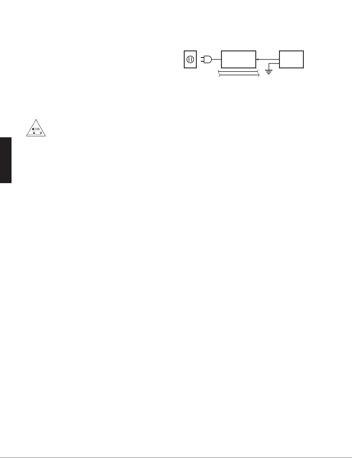
2. Leakage Current Measurement (For 120V Models Only)
When service has been completed, it is imperative to verify
that all exposed conductive surfaces are properly insulated
from supply circuits.
• Meter impedance should be equivalent to 1500 ohms shunted
by 0.15 μF.
RX-V373/HTR-3065
WALL
OUTLET
• Leakage current must not exceed 0.5mA.
• Be sure to test for leakage with the AC plug in both polarities.
EQUIPMENT
UNDER TEST
INSULATING
TABLE
AC LEAKAGE
TESTER OR
EQUIVALENT
For U model
“CAUTION”
“F1501: FOR CONTINUED PROTECTION AGAINST RISK OF FIRE, REPLACE ONLY WITH SAME TYPE 6A,
125V FUSE.”
For C model
CAUTION
F1501: REPLACE WITH SAME TYPE 6A, 125V FUSE.
ATTENTION
F1501: UTILISER UN FUSIBLE DE RECHANGE DE MÉME TYPE DE 6A, 125V.
WARNING: CHEMICAL CONTENT NOTICE!
This product contains chemicals known to the State of California to cause cancer, or birth defects or other reproductive
harm.
DO NOT PLACE SOLDER, ELECTRICAL/ELECTRONIC OR PLASTIC COMPONENTS IN YOUR MOUTH FOR ANY REASON
WHATSOEVER!
Avoid prolonged, unprotected contact between solder and your skin! When soldering, do not inhale solder fumes or
expose eyes to solder/flux vapor!
If you come in contact with solder or components located inside the enclosure of this product, wash your hands before
handling food.
About lead free solder /
All of the P.C.B.s installed in this unit and solder joints are
soldered using the lead free solder.
Among some types of lead free solder currently available,
it is recommended to use one of the following types for
the repair work.
• Sn + Ag + Cu (tin + silver + copper)
• Sn + Cu (tin + copper)
• Sn + Zn + Bi (tin + zinc + bismuth)
Caution:
As the melting point temperature of the lead free solder
is about 30°C to 40°C (50°F to 70°F) higher than that of
the lead solder, be sure to use a soldering iron suitable
to each solder.
無鉛ハンダについて
本機に搭載されているすべての基板およびハンダ付けに
よる接合部は無鉛ハンダでハンダ付けされています。
無鉛ハンダにはいくつかの種類がありますが、修理時に
は下記のような無鉛ハンダの使用を推奨します。
Sn+Ag+Cu(錫+銀+銅)
Sn+Cu(錫 + 銅)
Sn+Zn+Bi(錫 + 亜鉛 + ビスマス)
注意:
無鉛ハンダの融点温度は通常の鉛入りハンダに比べ 30 〜
40℃程度高くなっていますので、それぞれのハンダに合っ
たハンダごてをご使用ください。
2
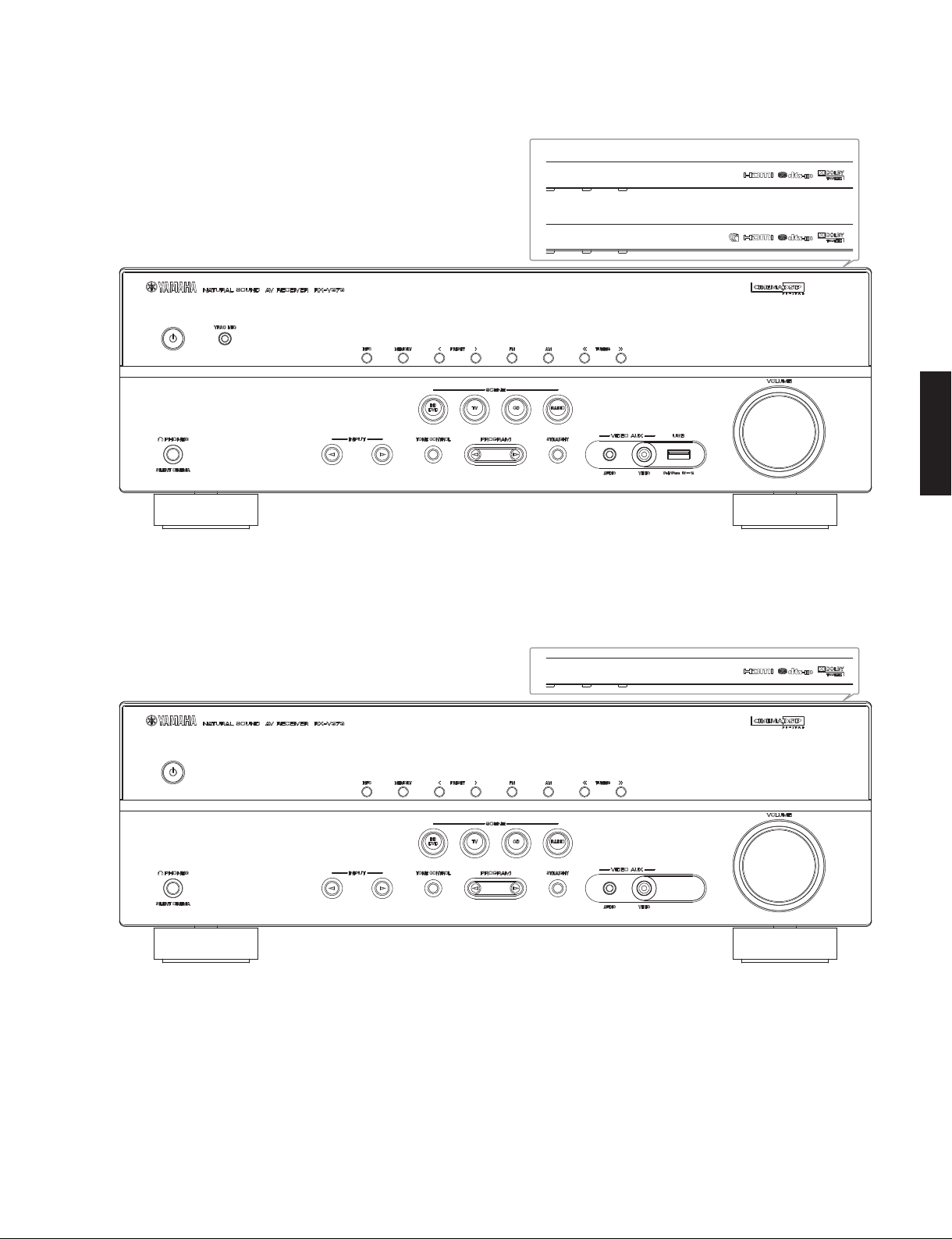
■ FRONT PANELS
RX-V373 (U, C, R, K, A, B, G, F, L, S, H, J models)
RX-V373/HTR-3065
U, C, R, K, A, B, G, F, L, S, H models
J model
RX-V373/HTR-3065
RX-V373 (T model)
3
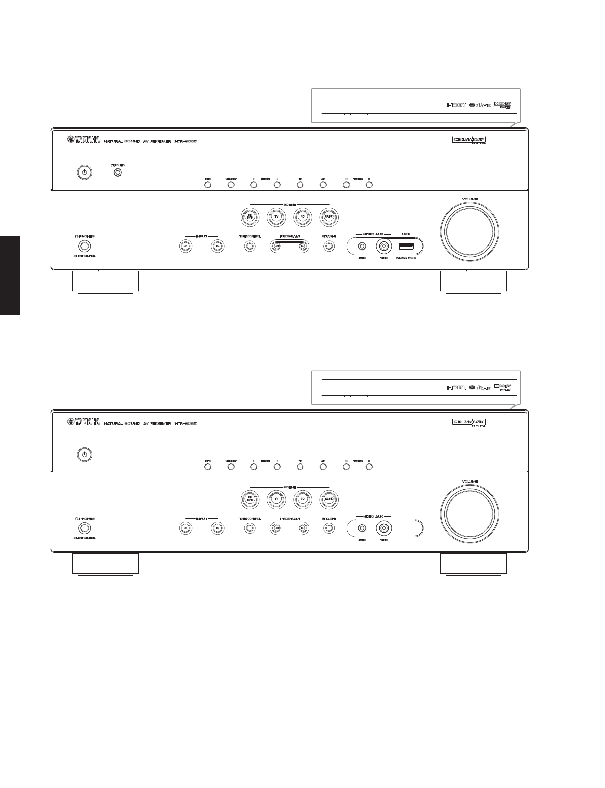
RX-V373/HTR-3065
HTR-3065 (U, C, R, K, A, B, G, F, L, S, H models)
RX-V373/HTR-3065
HTR-3065 (T model)
4
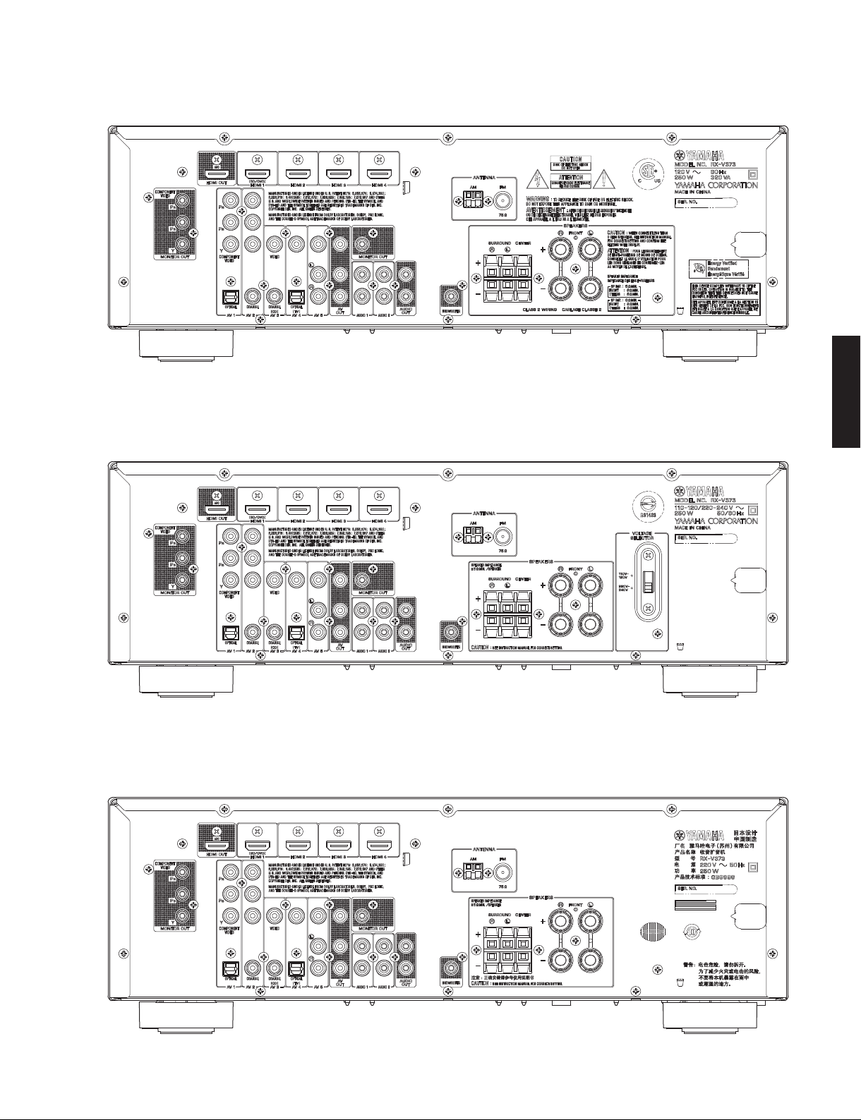
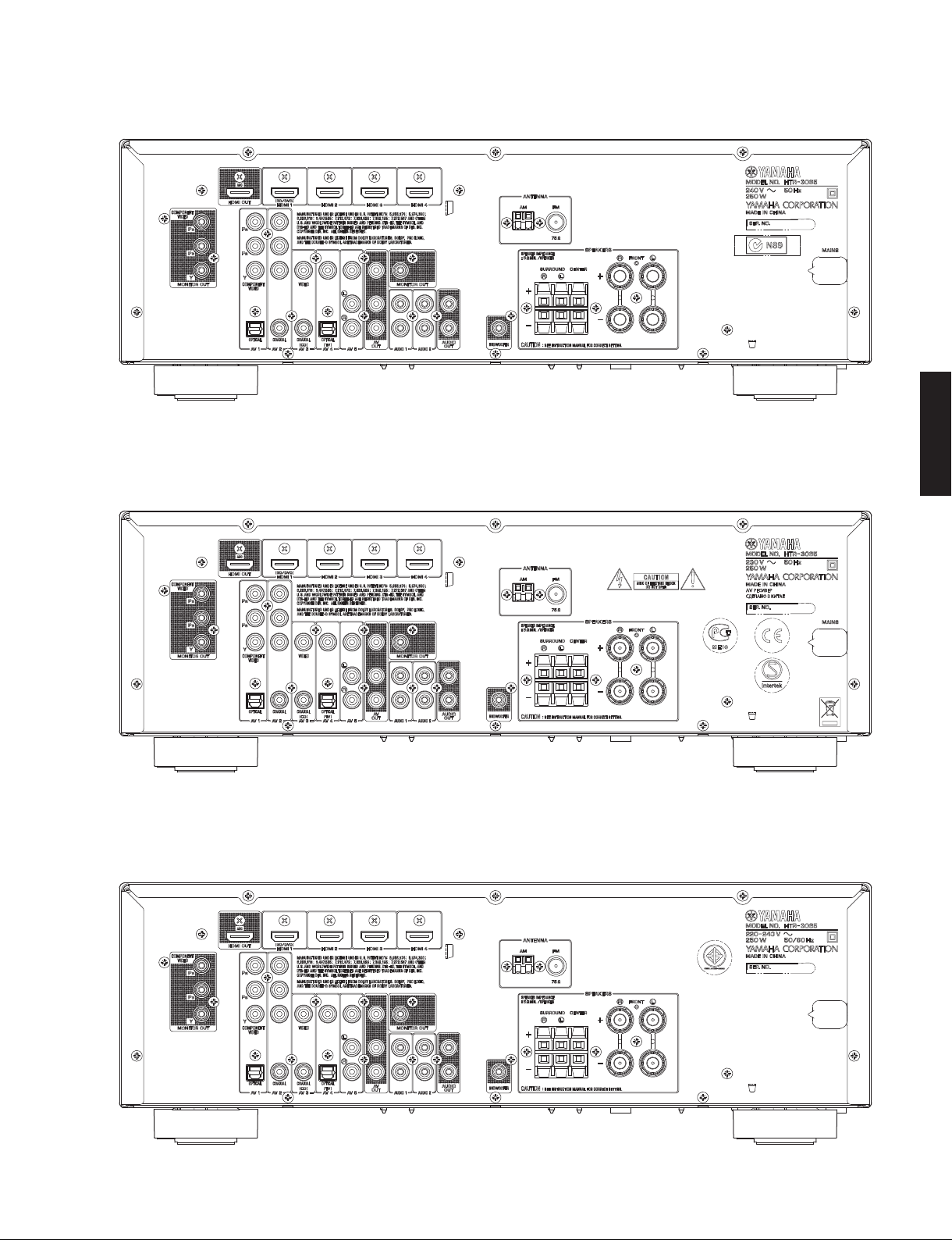
■ REAR PANELS
RX-V373 (U, C models)
RX-V373 (R, S models)
RX-V373/HTR-3065
RX-V373/HTR-3065
RX-V373 (T model)
5
RX-V373/HTR-3065
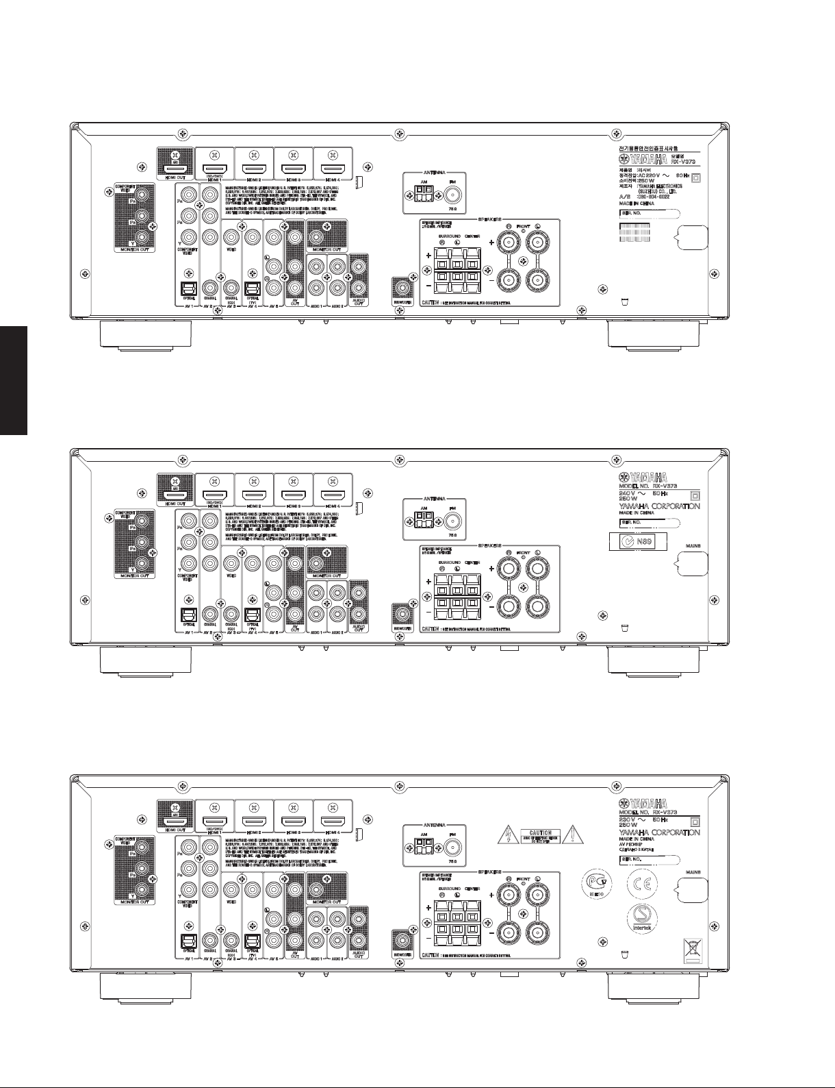
RX-V373 (K model)
RX-V373/HTR-3065
RX-V373 (A model)
RX-V373 (B, G, F models)
6
RX-V373 (L, H models)
RX-V373 (J model)
RX-V373/HTR-3065
RX-V373/HTR-3065
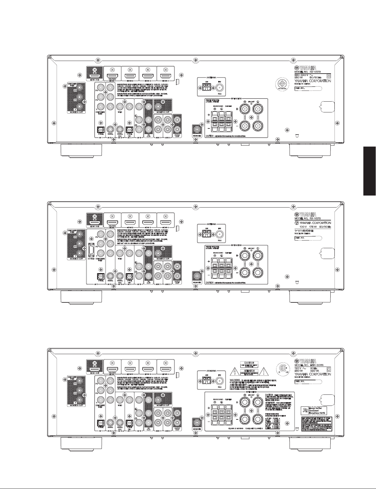
HTR-3065 (U, C models)
7
RX-V373/HTR-3065
HTR-3065 (R, S models)
RX-V373/HTR-3065
HTR-3065 (T model)
HTR-3065 (K model)
8
HTR-3065 (A model)
HTR-3065 (B, G, F models)
RX-V373/HTR-3065
RX-V373/HTR-3065
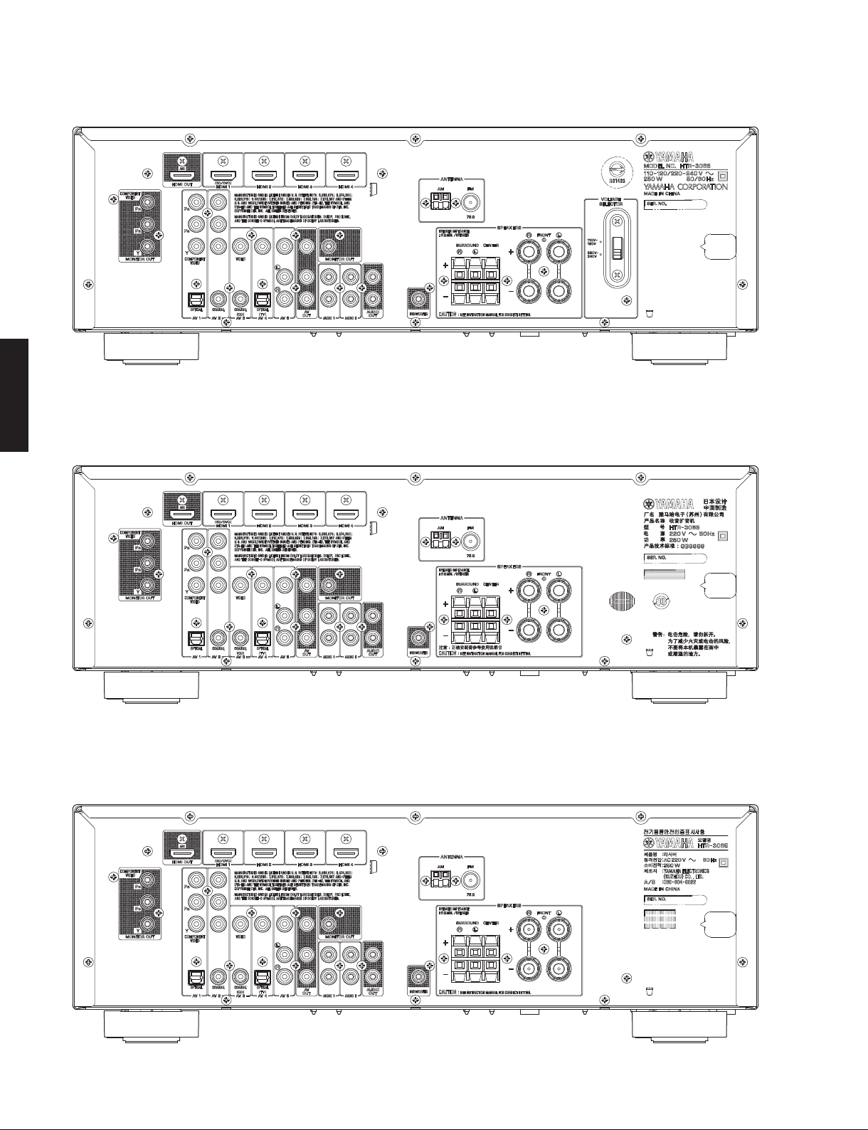
HTR-3065 (L, H models)
9
RX-V373/HTR-3065
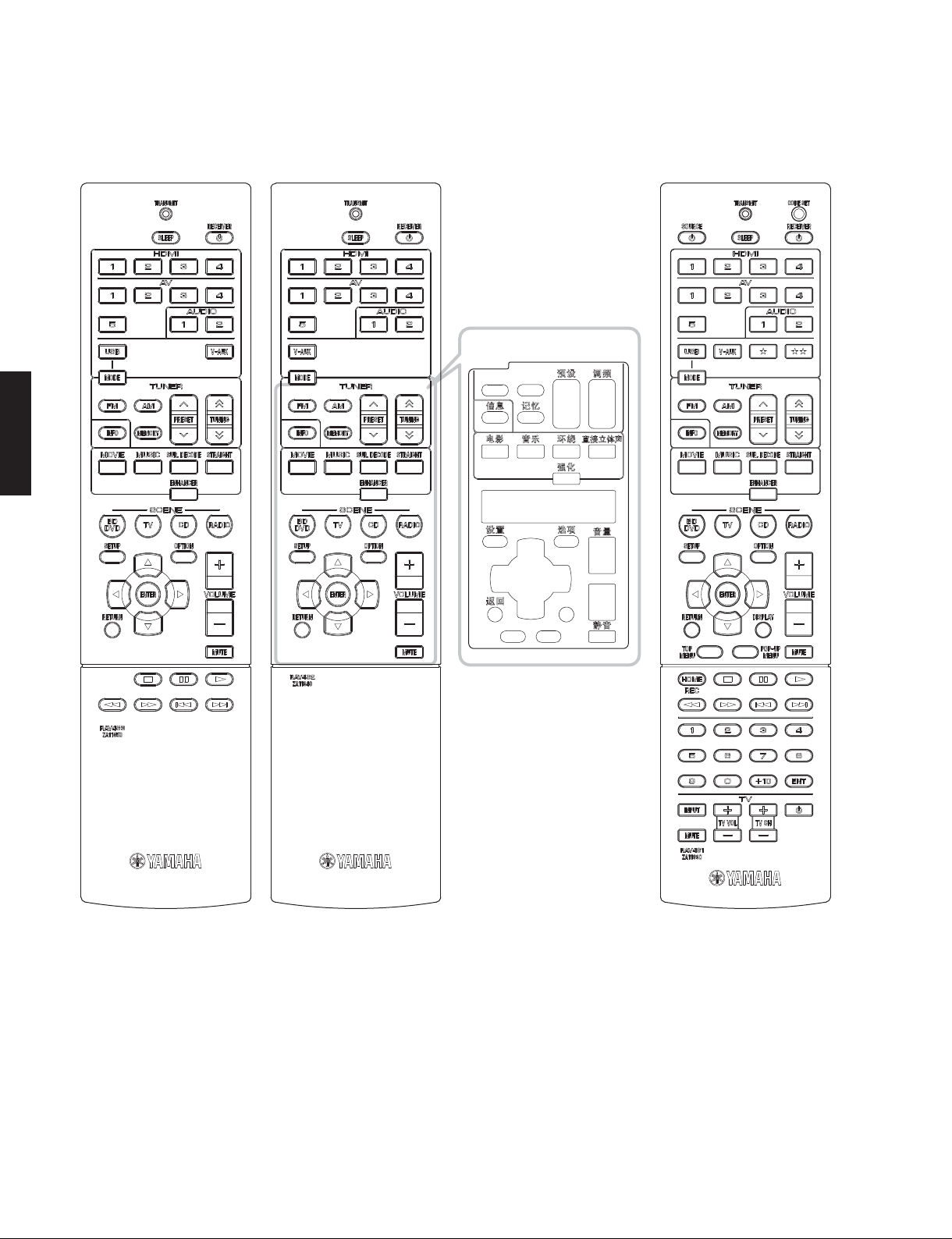
■ REMOTE CONTROL PANELS
(U, C, R, K,
B, G, F, L, S, H, J models)
RX-V373/HTR-3065
RAV463
RAV462
(T model)
RAV461
(A model)
Remote control sheet
10

RX-V373/HTR-3065
■ SPECIFICATIONS /
■ Audio Section /
Rated Output Power (Power Amp. Section) /
定格出力(パワーアンプ部)
(1 kHz, 0.9 % THD)
– 1 channel driven –
U, C models (8 ohms)
FRONT L/R ................................................................ 100 W/ch
CENTER .......................................................................... 100 W
SURROUND L/R ........................................................ 100 W/ch
R, T, K, A, B, G, F, L, S, H, J models (6 ohms)
FRONT L/R ................................................................ 100 W/ch
CENTER .......................................................................... 100 W
SURROUND L/R ........................................................ 100 W/ch
– 2 channels driven simultaneously –
U, C models (8 ohms)
FRONT L/R ...........................................................85 W + 85 W
CENTER ............................................................................ 85 W
SURROUND L/R ...................................................85 W + 85 W
(20 Hz to 20 kHz, 0.08 % THD)
– 2 channels driven simultaneously –
U, C models (8 ohms)
FRONT L/R ...........................................................70 W + 70 W
R, T, K, A, B, G, F, L, S, H, J models (6 ohms)
FRONT L/R ...........................................................65 W + 65 W
Maximum Effective Output Power /
(1 kHz, 10 % THD, 6 ohms / 1 channel driven)
[R, T, K, L, S, H, J models]
FRONT L/R ......................................................................... 135 W/ch
CENTER .................................................................................. 135 W
SURROUND L/R ................................................................135 W/ch
Dynamic Power Per Channel /
FRONT L/R drive
U, C models
(8 / 6 / 4 / 2 ohms) .................................. 110 / 130 / 160 / 180 W
R, T, K, A, B, G, F, L, S, H, J models
(6 / 4 / 2 ohms) ................................................ 110 / 130 / 150 W
Dynamic Headroom [U, C models]
8 ohms ..................................................................................0.23 dB
Damping Factor /
FRONT L/R to SPEAKER ................................................120 or more
Input Sensitivity/Input Impedance /
(1 kHz, 100 W/6 ohms)
AV5 etc. ............................................................200 mV / 47 k-ohms
Maximum Input Signal /
AV5 etc. (EFFECT ON) .............................................................. 2.3 V
Output Level/Output Impedance /
AV OUT ............................................................ 200 mV / 1.2 k-ohms
SUBWOOFER .........................................................1 V / 1.2 k-ohms
Headphone Jack Rated Output/Output Impedance /
ヘッドホン出力/出力インピーダンス
AV5 etc. input .....................................................100 mV / 470 ohms
Frequency Response /
AV5 etc., FRONT ..................................................................0 / -3 dB
Signal to Noise Ratio /
AV5, etc. (DIRECT) to SP OUT (Input shorted 250 mV)
.............................................................................. 100 dB or more
オーディオ部
ダイナミックパワー
ダンピングファクタ
最大許容入力
再生周波数帯域
信号対雑音比
参考仕様
実用最大出力
(20 Hz to 20 kHz, 8 ohms)
入力感度/入力インピーダンス
(1 kHz, 0.5 % THD)
出力電圧/出力インピーダンス
(1 kHz, 50 mV, 8 ohms)
(10 Hz to 100 kHz)
(IHF-A network)
(JEITA)
(IHF)
Residual Noise /
FRONT L/R to SP OUT ................................................150 μV or less
Channel Separation /
AV5, etc. (Input 5.1 k-ohms shorted)
1 kHz / 10 kHz ............................... 60 dB or more / 45 dB or more
Volume Control /
......................................... MUTE / -80 dB to +16.5 dB / 0.5 dB step
Tone Control Characteristics /
FRONT L/R
Bass
Boost/Cut ...................................... ±6 dB / 0.5 dB step, at 50 Hz
Turnover frequency ..........................................................350 Hz
Treble
Boost/Cut .....................................±6 dB / 0.5 dB step, at 20 kHz
Turnover frequency .........................................................3.5 kHz
Filter Characteristics /
FRONT, CENTER, SURROUND small (H.P.F.)
....................fc=40/60/80/90/100/110/120/160/200 Hz, 12 dB/oct.
SUBWOOFER small (L.P.F.)
....................fc=40/60/80/90/100/110/120/160/200 Hz, 24 dB/oct.
■ Video Section /
Video Signal Type /
U, C, R, K, S, J models ............................................................NTSC
T, A, B, G, F, L, H models ............................................................PAL
Composite Video Signal Level /
...............................................................................1 Vp-p / 75 ohms
Component Video Signal Level /
Y .............................................................................1 Vp-p / 75 ohms
Cb/Cr ..................................................................0.7 Vp-p / 75 ohms
D4 Video Signal /
Y .............................................................................1 Vp-p / 75 ohms
Cb/Cr ..................................................................0.7 Vp-p / 75 ohms
Video Maximum Input Level /
(VIDEO Conversion Off)
............................................................................... 1.5 Vp-p or more
Video Signal to Noise Ratio /
................................................................................... 50 dB or more
Monitor Out Frequency Response /
(VIDEO Conversion Off)
Component video signal level /
....................................................................5 Hz to 60 MHz, -3 dB
D4 video signal /
.....................................................................5 Hz to 60 MHz, -3 dB
残留ノイズ
可変範囲/ステップ
ビデオ部
D4 ビデオ信号
D4 ビデオ信号
(IHF-A Network)
チャンネルセパレーション
トーンコントロール特性
フィルタ特性
ビデオ信号方式
コンポジットビデオ信号
コンポーネントビデオ信号
[J model]
ビデオ最大許容入力
ビデオ信号対雑音比
モニター出力周波数帯域
コンポーネントビデオ信号
[J model]
RX-V373/HTR-3065
11
RX-V373/HTR-3065
■ FM Section /
Tuning Range /
U, C models ......................................................... 87.5 to 107.9 MHz
R, L, S, H models .............87.5 to 108.0 MHz / 87.50 to 108.00 MHz
T, K, A, B, G, F models ....................................87.50 to 108.00 MHz
J model ..................................................................76.0 to 90.0 MHz
50 dB Quieting Sensitivity /
(1 kHz, 100 % MOD.)
Mono ......................................................................... 3 μV (20.8 dBf)
Signal to Noise Ratio /
Mono ........................................................................................72 dB
Stereo ......................................................................................70 dB
Harmonic Distortion / 歪率 (1 kHz)
Mono ........................................................................................ 0.3 %
Stereo ......................................................................................0.5 %
Antenna Input /
....................................................................... 75 ohms unbalanced
RX-V373/HTR-3065
■ AM Section /
Tuning Range /
U, C models ........................................................... 530 to 1,710 kHz
R, L, S, H models ..................... 530 to 1,710 kHz / 531 to 1,611 kHz
T, K, A, B, G, F, J models .......................................531 to 1,611 kHz
Antenna /
..................................................................................... Loop antenna
アンテナ
FM部
受信周波数範囲
信号対雑音比
アンテナ入力
AM部
受信周波数範囲
50dBSN 感度
(IHF)
(IHF)
Finish /
仕上げ
[RX-V373]
T model .................................................................GD (Gold color)
U, C, R, T, K, A, B, G, F, L, S, H, J models ............BL (Black color)
R, K, B, G, F, L, H models ................................. TI (Titanium color)
[HTR-3065]
T model .................................................................GD (Gold color)
U, C, R, T, K, A, B, G, F, L, S, H models ................BL (Black color)
G model ............................................................ TI (Titanium color)
Accessories /
付属品
Remote control ..............................................................................x 1
Battery (R03, AAA, UM-4) .............................................................x 2
FM antenna (1.4 m) ......................................................................x 1
AM antenna (1.3 m) ......................................................................x 1
YPAO microphone (6.0 m) ............................................................x 1
Remote control sheet (T model) ...................................................x 1
* Specifications are subject to change without notice.
※ 参考仕様および外観は、製品の改良のため予告なく変更すること
があります。
U .......................U.S.A. model
C .................Canadian model
R ....................General model
T .................... Chinese model
K .....................Korean model
A ................Australian model
G .................European model
F .................... Russian model
L .................Singapore model
S ...................Brazirian model
H ..........................Thai model
J .................. Japanese model
B ......................British model
■ General /
Power Supply /
総合
電源電圧
U, C models ............................................................ AC 120 V, 60 Hz
R, S model ...................................AC 110–120/220–240 V, 50/60 Hz
T model ................................................................... AC 220 V, 50 Hz
K model .................................................................. AC 220 V, 60 Hz
A model .................................................................. AC 240 V, 50 Hz
B, G, F models ........................................................ AC 230 V, 50 Hz
L, H models ............................................... AC 220–240 V, 50/60 Hz
J model .............................................................. AC 100 V, 50/60 Hz
Power Consumption /
消費電力
U, C models ..............................................................250 W / 320 VA
R, T, K, A, B, G, F, L, S, H models ........................................... 250 W
J model ...................................................................................175 W
Standby Power Consumption (reference data) /
待機時消費電力(参考値)
U, C, T, K, A, B, G, F, L, H, J models ............................0.3 W or less
R, S models ..................................................................0.5 W or less
Maximum Power Consumption [R, L, S, H models]
................................................................................................ 470 W
Dimensions (W x H x D) /
寸法(幅 × 高さ × 奥行き)
..................................... 435 x 151 x 315 mm (17-1/8" x 6" x 12-3/8")
Weight / 質量
............................................................................... 7.5 kg (16.5 lbs.)
Manufactured under license from Dolby Laboratories. Dolby, Pro Logic and
the double-D symbol are trademarks of Dolby Laboratories.
ドルビーラボラトリーズからの実施権に基づき製造されています。「ドルビー」、
「PROLOGIC」およびダブル D 記号
DTS-HD, the Symbol, & DTS-HD and the Symbol together are registered
trademarks of DTS, Inc. Product includes software. © DTS, Inc. All Rights
Reserved.
DTS-HD および記号は DTS 社の登録商標です。また、DTS-HD ロゴは DTS 社の
商標です。製品にはソフトウェアを含みます。著作権 DTS 社。不許複製。
iPhone, iPod, iPod classic, iPod nano and iPod touch are trademarks of
Apple Inc., registered in the U.S. and other countries.
iPhone、iPod、iPodclassic、iPodnano、iPodtouch は、米国およびその他
の国々で登録されている AppleInc. の商標です。
“HDMI,” the “HDMI” logo and “High-Definition Multimedia Interface” are
trademarks, or registered trademarks of HDMI Licensing LLC.
HDMI、HDMI ロゴ、および High-Defi nitionMultimediaInterface は、HDMI
Licensing,LLC の商標または登録商標です。
はドルビーラボラトリーズの商標です。
12
“x.v.Color” is a trademark of Sony Corporation.
「x.v.Color」は、ソニー株式会社の商標です。
“SILENT CINEMA” is a trademark of Yamaha Corporation.
「サイレントシネマ™ SILENTCINEMA™」はヤマハ株式会社の登録商標です。
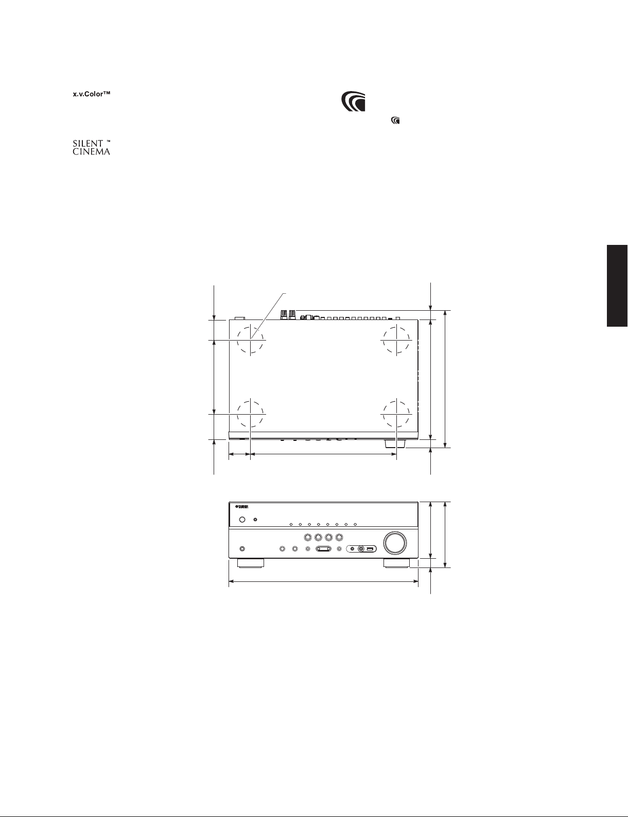
• DIMENSIONS
AAC ロゴマーク
RX-V373/HTR-3065
はドルビーラボラトリーズの商標です。
RX-V373/HTR-3065
Top view
46
(1-3/4")
170 (6-5/8")
50
58
(2")
(2-1/4")
Front view
ø 60
335 (13-1/4")
435 (17-1/8")
23
(7/8")
315 (12-3/8")
274 (10-3/4")
18
(3/4")
151 (6")
130 (5-1/8")21
(7/8")
Unit: mm (inch)
単位:mm(インチ)
13
RX-V373/HTR-3065
• SELECT MENU
Sound field parameters
Parameter
Category Program
MOVIE Standard
RX-V373/HTR-3065
MUSIC Hall in Munich
SUR. DECODE
STRAIGHT
ENHANCER Enhancer On / Off
: Setting is possible
●
設定可
Spectacle
Sci-Fi
Adventure
Drama
Mono Movie
Sports
Action Game
Roleplaying Game
Hall in Vienna
Chamber
Cellar Club
The Roxy Theatre
The Bottom Line
Music Video
2ch Stereo
5ch Stereo
●
*1
Decode Type
Panorama: Off / On, [Off]
Center Width: 0 to 7, [3]
Dimension: -3 to +3, [0]
Center Image: 0.0 to 1.0, [0.3]
*1 Decode Type
Pro Logic
PLII Movie
Decode Type
PLII Music
PLII Game
Neo: 6 Cinema
Neo: 6 Music
14
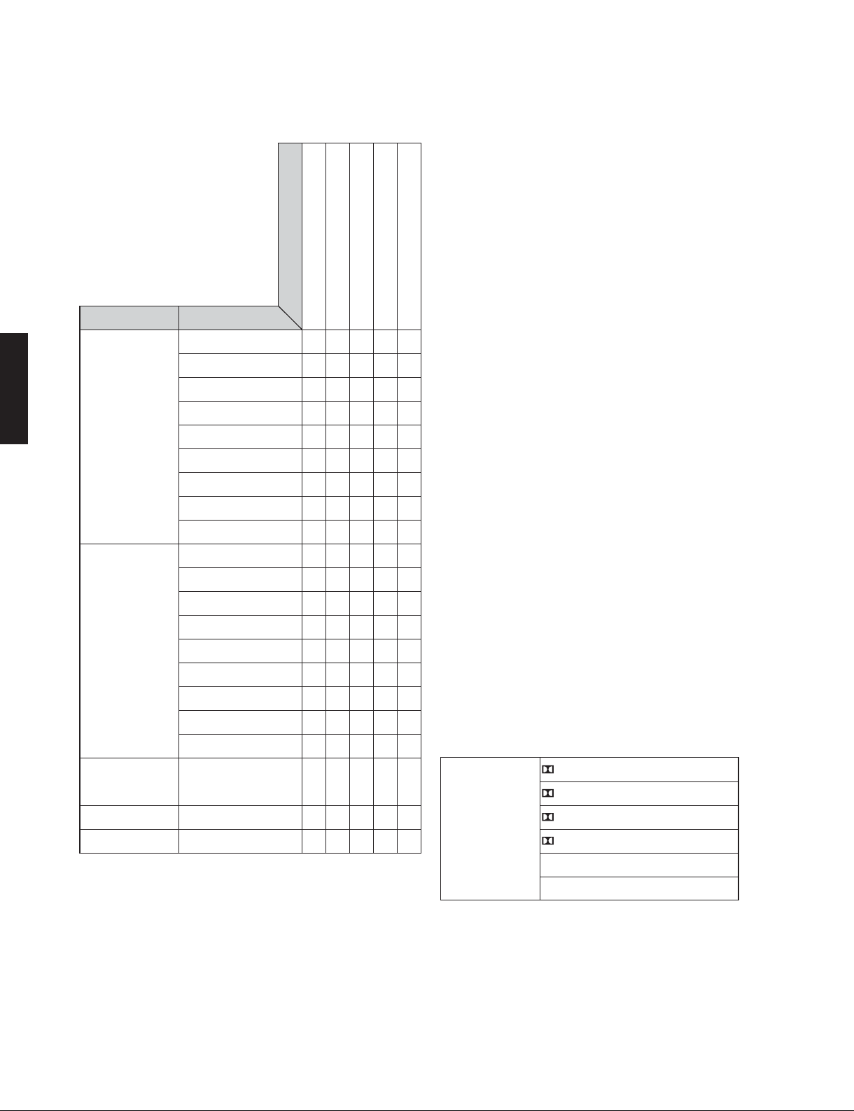
• SET MENU TABLE
RX-V373/HTR-3065
MAIN
MENU
Speaker Configuration Subwoofer [Use] / None
HDMI Configuration HDMI Control [Off] / On
SUB-MENU PARAMETER VALUE [INITIAL VALUE]
Front [Small] / Large
Center [Small] / Large / None
Surround [Small] / Large / None
Crossover 40 Hz / 60 Hz / [80 Hz] / 90 Hz / 100Hz / 110 Hz / 120 Hz / 160 Hz /
200 Hz
Subwoofer Phase [Normal] / Reverse
Extra Bass [Off] / On
Distance Unit Feet / Meter
Front L 0.30 to 24.00 m, [3.05 m], 0.05 m step
Front R 1.0 to 80.0 ft, [10.0 ft], 0.2 ft step
Center 0.30 to 24.00 m, [2.60 m], 0.05 m step
1.0 to 80.0 ft, [8.6 ft], 0.2 ft step
Surround L 0.30 to 24.00 m, [2.45 m], 0.05 m step
Surround R 1.0 to 80.0 ft, [8.0 ft], 0.2 ft step
Subwoofer 0.30 to 24.00 m, [3.05 m], 0.05 m step
1.0 to 80.0 ft, [10.0 ft], 0.2 ft step
Level Front L
Front R
Center
Surround L -10.0 to +10.0 dB, [-1.0 dB], 0.5 dB step
Surround R
Subwoofer -10.0 to +10.0 dB, [0.0 dB], 0.5 dB step
Equalizer EQ Select PEQ / [GEQ] / Off
GEQ Edit Front L 63 Hz ···········||···········
Front R 160 Hz ···········||···········
Center 400 Hz ···········||···········
Surround L 1 kHz ···········||··········· -6.0 to +6.0 dB, [0 dB], 0.5 dB step
Surround R 2.5 kHz ···········||···········
6.3 kHz ···········||···········
16 kHz ···········||···········
Test Tone [Off] / On
Audio Output Amp Off / [On]
HDMI OUT (TV) [Off] / On
TV Audio Input AV1 / AV2 / AV3 / [AV4] / AV5 / AUDIO1 / AUDIO2
Standby Sync Off / On / [Auto]
ARC Off / [On]
SCENE
BD / D
TV
CD
RADIO
VD
-10.0 to +10.0 dB, [0.0 dB], 0.5 dB step
* “PEQ” is available only when the YPAO has been performed
“PEQ”
* This setting is available only when “HDMI Control” is set to “Off”.
“HDMI Control”が“Off”
Off / [On]
[Off] / On
は自動測定(
YPAO
)を行った場合のみ選択可能
の場合のみ設定可能
RX-V373/HTR-3065
15
RX-V373/HTR-3065
MAIN
MENU
Sound DSP Parameter Panorama [Off] / On
ECO Auto Power Down U, C, R, T, K, A, L, S, H, J models: [Off] / 2 hours / 4 hours / 8 hours /
Function Input Rename Input sources: HDMI1 / HDMI2 / HDMI3 / HDMI4 / AV1 / AV2 / AV3 /
RX-V373/HTR-3065
Language English (English) / Français (Franch) / Deutsch (German) /
(U, C, R, T, K, A, B, G, F, L, S, H models) Español (Spanish) / РУccкий (Russian) / 中文 (Chinese)
SUB-MENU PARAMETER VALUE [INITIAL VALUE]
Center Width 0 to 7, [3]
Dimension -3 to +3, [0]
Center Image 0.0 to 1.0, [0.3]
Lipsync Select Manual / [Auto]
Adjustment 0 to 250 ms, [0 ms], 1 ms step
Vol ume Dynamic Range [Maximum] / Standard / Min/Auto
Max Volume -30.0 to +15.0 dB / +16.5 dB (Maximum volume), [+16.5 dB], 5.0 dB step
Initial Volume [Off] / Mute / -80.0 to +16.5 dB, 0.5 dB step
12 hours
B, G, F models: Off / 2 Hours / 4 Hours / [8 Hours] / 12 Hours
ECO Mode [Off] / On
AV4 / AV5 / AUDIO1 / AUDIO2 / USB / V-AUX
Input is possible to 9 characters
Input possible Character type
Capital: A to Z
Small: a to z
Figure: 0 to 9
Symbols: # * + , - etc.
Space
Preset name select: Blu-ray / DVD / SetTopBox / Game / TV / DVR /
CD / CD-R / Satellite / VCR / Tape / MD / PC /
iPod / HD DVD
Dimmer -4 to 0 (higher to brighten), [-2]
Memory Guard [Off] / On
16
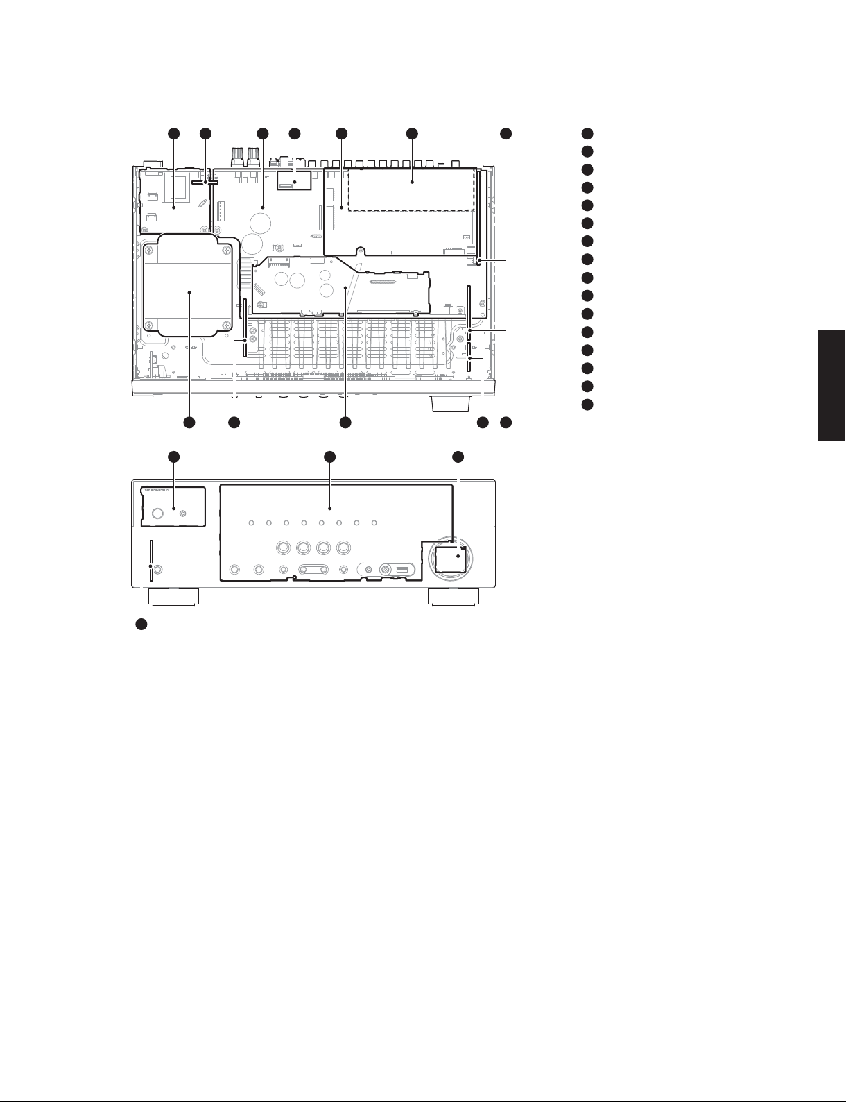
■ INTERNAL VIEW
RX-V373/HTR-3065
1
12 10 8
13 14 15
3524 6 7
1
OPERATION (3) P.C.B.
2
MAIN (3) P.C.B. (R, S models)
3
MAIN (1) P.C.B.
4
AM/FM TUNER
5
DIGITAL P.C.B.
6
MAIN (2) P.C.B.
7
OPERATION (4) P.C.B.
8
MAIN (4) P.C.B.
9
OPERATION (9) P.C.B.
10
OPERATION (2) P.C.B.
11
OPERATION (8) P.C.B.
12
POWER TRANSFORMER
13
OPERATION (7) P.C.B.
14
OPERATION (1) P.C.B.
15
OPERATION (6) P.C.B.
16
OPERATION (5) P.C.B.
911
RX-V373/HTR-3065
16
■ SERVICE PRECAUTIONS /
サービス時の注意事項
Safety measures
• Some internal parts in this product contain high voltages
and are dangerous.
Be sure to take safety measures during servicing, such
as wearing insulating gloves.
• Note that the capacitors indicated below are dangerous
even after the power is turned off because an electric
charge remains and a high voltage continues to exist
there.
Before starting any repair work, connect a discharging
resistor (5 k-ohms/10 W) to the terminals of each
capacitor indicated below to discharge electricity.
The time required for discharging is about 30 seconds
per each.
C46 and C47 on MAIN (1) P.C.B.
C1501 on OPERATION (3) P.C.B.
安全対策
・ この製品の内部には高電圧部分があり危険です。修理
の際は、絶縁性の手袋を使用するなどの安全対策を
行ってください。
・ 下記のコンデンサには電源を OFF にした後も電荷が残
り、高電圧が維持されており危険です。
修理作業前に放電用抵抗(5k Ω /10W)を下記の各コ
ンデンサの端子間に接続して放電してください。
放電所用時間は各々約 30 秒間です。
MAIN(1)P.C.B. の C46、C47
OPERATION(3)P.C.B. の C1501
詳しくは “PRINTEDCIRCUITBOARDS” を参照してくだ
さい。
For details, refer to “PRINTED CIRCUIT BOARDS”.
17
RX-V373/HTR-3065
■ DISASSEMBLY PROCEDURES /
(Remove parts in the order as numbered.)
Disconnect the power cable from the AC outlet.
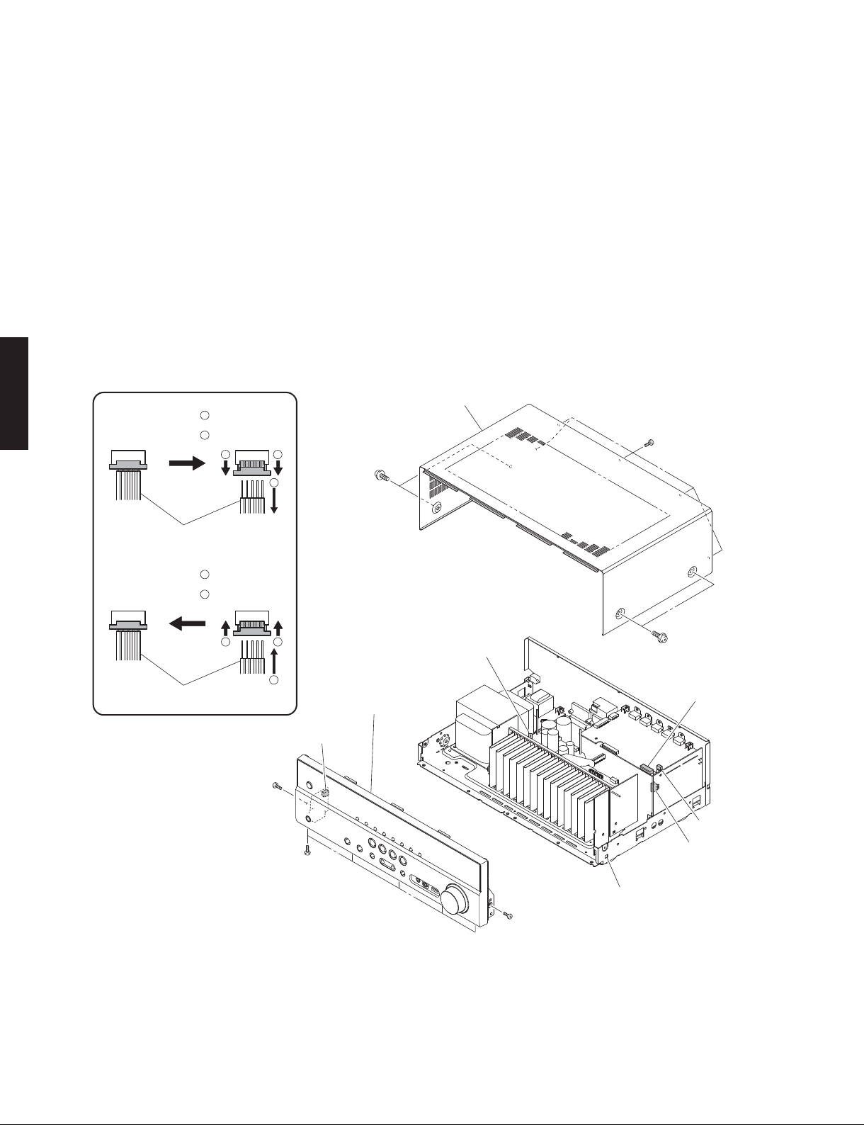
1. Removal of Top Cover
a. Remove 5 screws (①) and 4 screws (②). (Fig. 1)
b. Lift the rear of the top cover to remove it. (Fig. 1)
2. Removal of Front Panel Unit
a. Remove 7 screws (③). (Fig. 1)
b. Remove CB166, CB193, CB221 and CB281. (Fig. 1)
c. Unlock and remove CB136. (Fig. 1)
d. Release hook, and then remove the front panel unit.
(Fig. 1)
Connected
RX-V373/HTR-3065
Remove CB136 and CB262
Unlock the connector
1
コネ クター ロック解 除
Remove the cable
2
接続
ケーブルを外す
1 1
分解手順
(番号順に部品を外してください。)
AC 電源コンセントから、電源コードを抜いてください。
1. トップカバーの外し方
a. ①のネジ 5 本、②のネジ 4 本を外します。(Fig.1)
b. トップカバーの後部を持ち上げ、外します。(Fig.1)
2. フロントパネルユニットの外し方
a. ③のネジ 7 本を外します。(Fig.1)
b. CB166、CB193、CB221、CB281を外します。(Fig.1)
c. ロックを外し、CB136を外します。(Fig.1)
d. フック 1 箇所を外し、フロントパネルユニットを外し
ます。(Fig.1)
Top cover
トップカバー
①
②
2
Cable
ケーブル
Connect CB136 and CB262
Connected
接続
Lock the connector
1
コネ クター ロック
Insert the cable
2
ケーブルを差し込む
1 1
Cable
ケーブル
CB136
2
Front panel unit
フロントパネルユニット
②
CB221
CB166
③
CB281
CB193
③
Hook
③
18
Fig. 1
RX-V373/HTR-3065
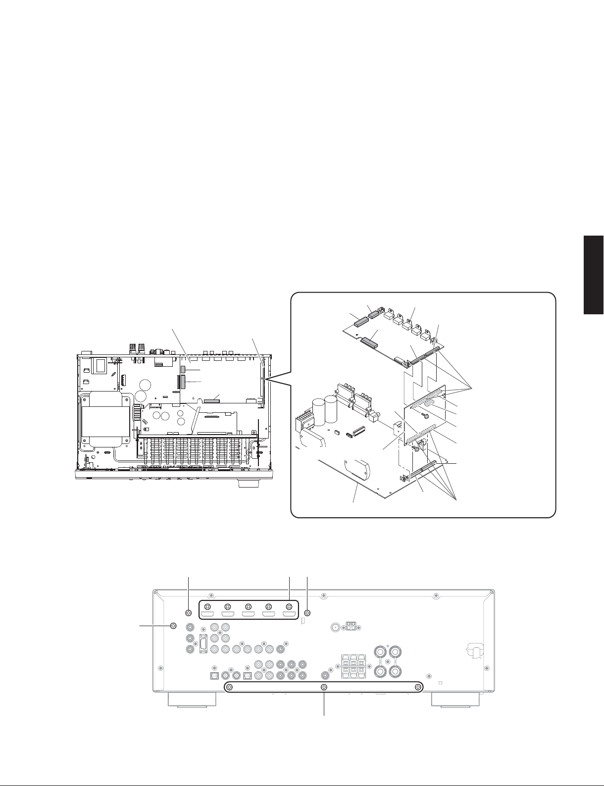
3. Removal of DIGITAL P.C.B.
a. Remove CB222 and CB223 (Fig. 2)
b. Unlock and remove CB262. (Fig. 2)
c. Remove screw (④). (Fig. 2)
d. Remove 2 screws (⑤) and 5 screws (⑥). (Fig. 3)
e. Remove the DIGITAL P.C.B. which is connected
directly to the OPERATION (4) P.C.B. with board-toboard connectors. (Fig. 2)
4. Removal of OPERATION (4) P.C.B.
a. Remove CB194. (Fig. 2)
b. Remove screw (⑦). (Fig. 2)
c. Remove screw (⑧). (Fig. 3)
d. Remove the OPERATION (4) P.C.B. which is
connected directly to the MAIN (1) P.C.B. with boardto-board connectors. (Fig. 2)
DIGITAL P.C.B.
OPERATION (4) P.C.B.
3. DIGITALP.C.B. の外し方
a. CB222、CB223 を外します。(Fig.2)
b. ロックを外し、CB262 を外します。(Fig.2)
c. ④のネジ 1本を外します。(Fig.2)
d. ⑤のネジ 2 本、⑥のネジ 5 本を外します。(Fig.3)
e. DIGITALP.C.B.を外します。ただし、DIGITALP.C.B. は
OPERATION(4)P.C.B. に基板対基板コネクターで直
接接続されています。(Fig.2)
4. OPERATION(4)P.C.B. の外し方
a. CB194 を外します。(Fig.2)
b. ⑦のネジ 1 本を外します。(Fig.2)
c. ⑧のネジ 1 本を外します。(Fig.3)
d. OPERATION(4)P.C.B. を外します。ただし、
OPERATION(4)P.C.B. は MAIN(1)P.C.B. に基板対基
板コネクターで直接接続されています。(Fig.2)
CB223
CB222
CB262
DIGITAL P.C.B.
CB263
CB264
RX-V373/HTR-3065
CB223
CB222
CB262
OPERATION (4) P.C.B.
MAIN (1) P.C.B.
CB191
④
⑦
CB22
Board-to-board
connectors
基板対基板コネクター
CB196
CB194
CB195
CB192
CB21
Board-to-board
connectors
基板対基板コネクター
Fig. 2
⑤
⑤
⑧
⑥
Fig. 3
⑨
19
RX-V373/HTR-3065
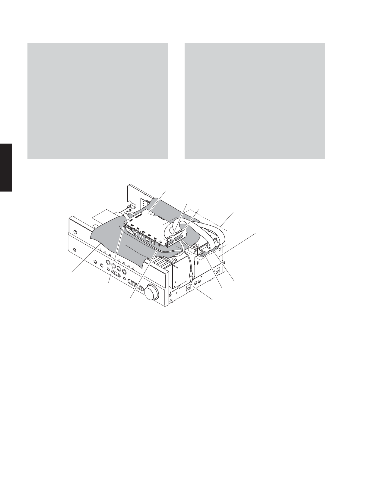
When checking the DIGITAL P.C.B.:
• Put the rubber sheet and cloth over this unit, and
place the DIGITAL P.C.B. on them. (Fig. 4)
• Connect ST201 on DIGITAL P.C.B. to the chassis
with a ground lead. (Fig. 4)
• Reconnect all cables (connectors) that have been
disconnected. Be sure to use the P.C.B. CHECKING
JIG (Part No. WW483800) to connect between the
following connectors.
CB263 on DIGITAL P.C.B. – CB196 on OPERATION
(4) P.C.B.
CB264 on DIGITAL P.C.B. – CB195 on OPERATION
(4) P.C.B.
• When connecting the flexible flat cable, be careful
with polarity.
RX-V373/HTR-3065
DIGITALP.C.B. をチェックする場合には:
・ 本機の上にゴムシートと布を敷き、その上に DIGITAL
・ DIGITALP.C.B. の ST201 のアースをリード線でシャー
・ 外したケーブル(コネクター)をすべて接続しま
・ フラットケーブルを接続する際、極性に注意してく
DIGITAL P.C.B.
CB263
P.C.B. を置きます。(Fig.4)
シに接続してください。(Fig.4)
す。ただし下記のコネクター間を接続するには
P.C.B. チェック用冶具(部品番号 :WW483800)を使
用してください。
DIGITALP.C.B.のCB263‒OPERATION(4)P.C.B.の
CB196
DIGITALP.C.B.のCB264‒OPERATION(4)P.C.B.の
CB195
ださい。
CB264
P.C.B. CHECKING JIG
P.C.B.チェック用冶具
Rubber sheet and cloth
ゴムシートと布
ST201
Ground lead
アース線
OPERATION (4) P.C.B.
CB196
CB195
Chassis
シャーシ
Fig. 4
20
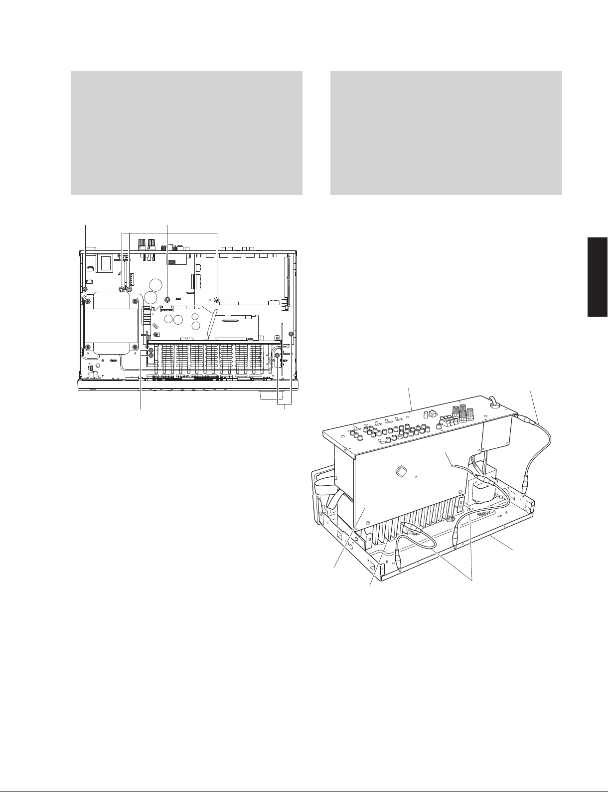
RX-V373/HTR-3065
When checking the MAIN (1) P.C.B.:
a. Remove the top cover. (Fig. 1)
b. Remove 3 screws (⑨). (Fig. 3)
c. Remove 5 screws (⑩) and 4 screws (⑪). (Fig. 5)
d. Place the P.C.B.s (with rear panel) upright. (Fig. 6)
e. Connect the heatsink, rear panel and MAIN (1) P.C.B.
(G3) to the chassis with a ground lead. (Fig. 6)
⑩
⑪
MAIN(1)P.C.B. をチェックする場合には:
a. トップカバーを外します。(Fig.1)
b. ⑨のネジ 3 本を外します。(Fig.3)
c. ⑩のネジ 5 本、⑪のネジ 4 本を外します。(Fig.5)
d. リアパネルと一緒に P.C.B. を立ち上げて置きます。
(Fig.6)
e. ヒートシンク、リアパネル、MAIN(1)P.C.B. の G3
のアースをリード線でシャーシに接続してください。
(Fig.6)
RX-V373/HTR-3065
Rear panel
リアパネル
⑩⑩
Fig. 5
MAIN (1) P.C.B.
Heatsink
ヒートシンク
Ground lead
アース線
G3
Chassis
シャーシ
Ground lead
アース線
Fig. 6
21

RX-V373/HTR-3065
■ UPDATING FIRMWARE /
When the following parts are replaced, the firmware must
be updated to the latest version.
DIGITAL P.C.B.
OSD FLASH ROM: IC201 on DIGITAL P.C.B.
USB FLASH ROM: IC222 on DIGITAL P.C.B.
DSP FLASH ROM: IC243 on DIGITAL P.C.B.
Note: There are 2 types procedures for updating the
● Confirmation of firmware version and checksum
Before and after updating the firmware, check the
firmware version and checksum by using the selfdiagnostic function menu.
Start up the self-diagnostic function and select “25.
RX-V373/HTR-3065
ROM VER/SUM” menu.
Using the sub-menu, have the firmware version and
checksum displayed, and note them down.
(See “SELF-DIAGNOSTIC FUNCTION”)
* When the firmware version is different from
written one after updating, perform the updating
procedure again from the beginning.
ファームウェアのアップデート
firmware. One is for the U, C, R, K, A, B, G, F, L, S,
H and J models, and another is for the T model.
Perform either depending on the destinations.
下記の部品を交換した場合、ファームウェアを最新バー
ジョンにアップデートする必要があります。
DIGITALP.C.B.
OSD フラッシュ ROM: DIGITALP.C.B. の IC201
USB フラッシュ ROM: DIGITALP.C.B. の IC222
DSP フラッシュ ROM: DIGITALP.C.B. の IC243
注意 : ファームウェアアップデートの手順は2種類あ
ります。ひとつは U、C、R、K、A、B、G、F、L、S、
H、J 仕向け用で、もうひとつは T 仕向け用です。
仕向け先に応じてどちらかを実行してください。
● ファームウェアのバージョンとチェックサムの
確認
ファームウェアのアップデートの前後に、ファーム
ウェアのバージョンとチェックサムをダイアグで確
認します。
ダイアグを起動し、“25.ROM VER/SUM” メニューを
選択します。
サブメニューでファームウェアのバージョンと
チェックサムを表示し、それらを書きとめます。
(「ダイアグ」参照)
※ アップデート後、ファームウェアのバージョンが
書き込まれたものと異なる場合、アップデートの
操作を最初からやり直してください。
● Initializing the back-up IC
(EEPROM: IC221 on DIGITAL P.C.B.)
After updating the firmware, the back-up IC MUST
be initialized by the following procedure store the
setting information (soundfield parameters, system
memory and tuner presetting, etc.) properly.
Start up the self-diagnostic function and select “24.
FACTORY PRESET” menu. (See “SELF-DIAGNOSTIC
FUNCTION”)
Select “PRESET RSRV”, press the “
turn off the power once and turn on the power again.
Then the back-up IC is initialized.
” (Power) key to
● バックアップ IC の初期化
(EEPROM:DIGITALP.C.B. の IC221)
ファームウェアのアップデート後、設定情報(音
場プログラムのパラメーターやシステムメモリー、
チューナープリセット等)を正常に保存するために、
下記の方法でバックアップ IC を初期化する必要が
あります。
本機のダイアグを起動し、“24.FACTORYPRESET” メ
ニューを選択します。
(「ダイアグ」参照)
“PRESETRSRV” を選択し、“
電源を一度きってから、もう一度電源を入れるとバッ
クアップ IC が初期化されます。
”(電源)キーを押して
22
RX-V373/HTR-3065
Updating
U, C, R, K, A, B, G, F, L, S, H and J models
● Required Tools
• USB storage device
• Firmware
RX-V373/HTR-3065: R0303-xxx.bin
● Preparation
1. Download the latest firmware from the specified
download source to the folder of the PC.
2. Copy the latest firmware from the PC to the root
folder of the USB storage device.
Note: When the latest firmware is copied to a sub-
folder of the USB storage device, the update
will not proceed.
● Operation Procedures
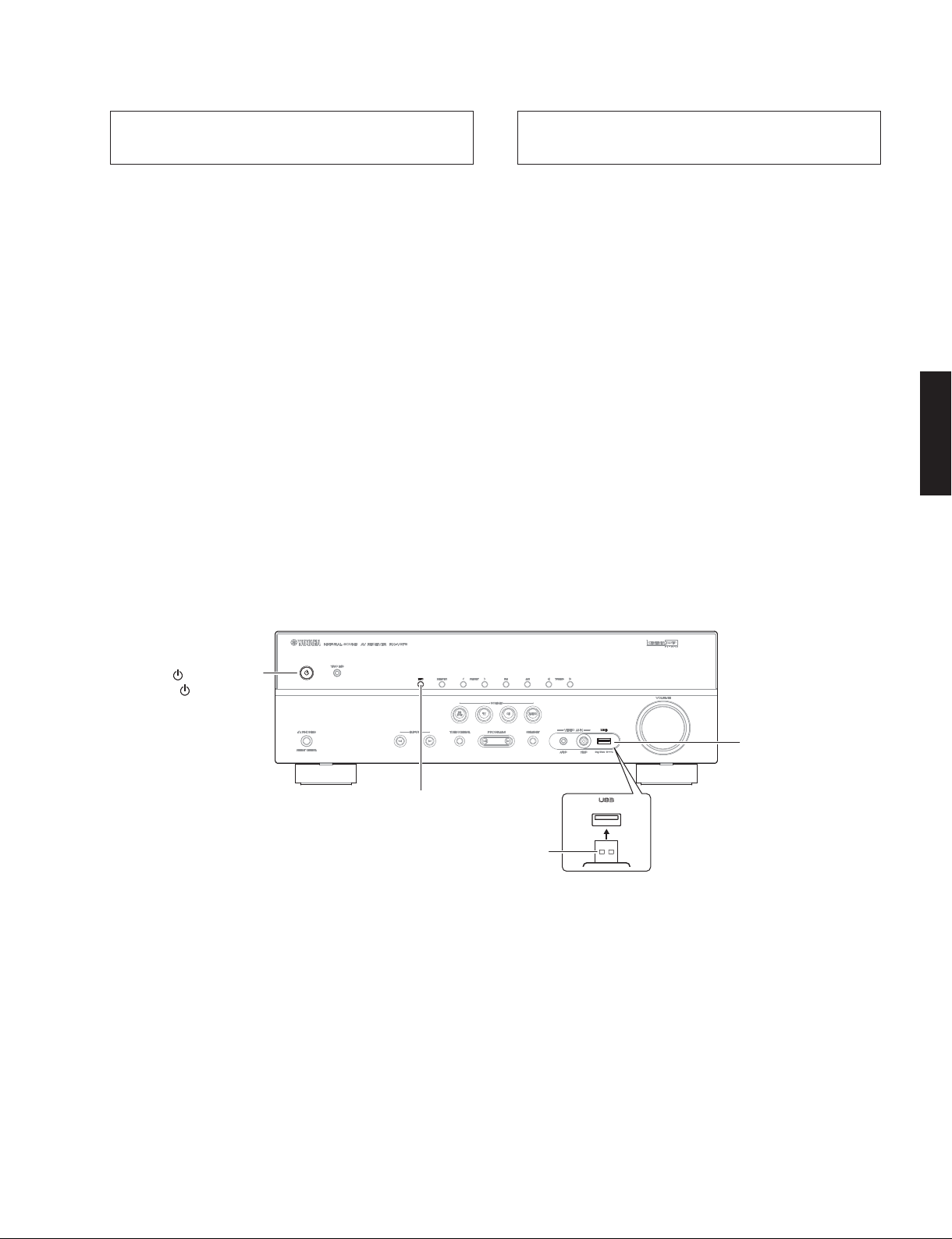
1. Insert the USB storage device to the USB jack.
(Fig. 1)
2. While pressing the “INFO” key, connect the power
cable to the AC outlet. (Fig. 1)
U、C、R、K、A、B、G、F、L、S、H、J
仕向けのアップデート
● 必要なツール
・ USB フラッシュメモリー
・ ファームウェア
RX-V373 / HTR-3065:R0303-xxx.bin
● 準備
1. 指定のダウンロード先から、最新のファームウェ
アを PC のフォルダへダウンロードしてください。
2. PC から USB フラッシュメモリーのルートフォル
ダへ最新のファームウェアをコピーします。
注意 : 最新のファームウェアをサブフォルダにコピー
した場合、書き込みはできません。
● 操作手順
1. USB 端子に USB フラッシュメモリーを差し込みま
す。(Fig.1)
2. “INFO” キーを押しながら、電源コードを AC コン
セントに接続します。(Fig.1)
RX-V373/HTR-3065
" " (Power) key
""(電源)キー
USB jack
USB 端子
"INFO" key
“INFO” キー
USB storage device
USB フラッシュメモリー
Fig. 1
23
RX-V373/HTR-3065
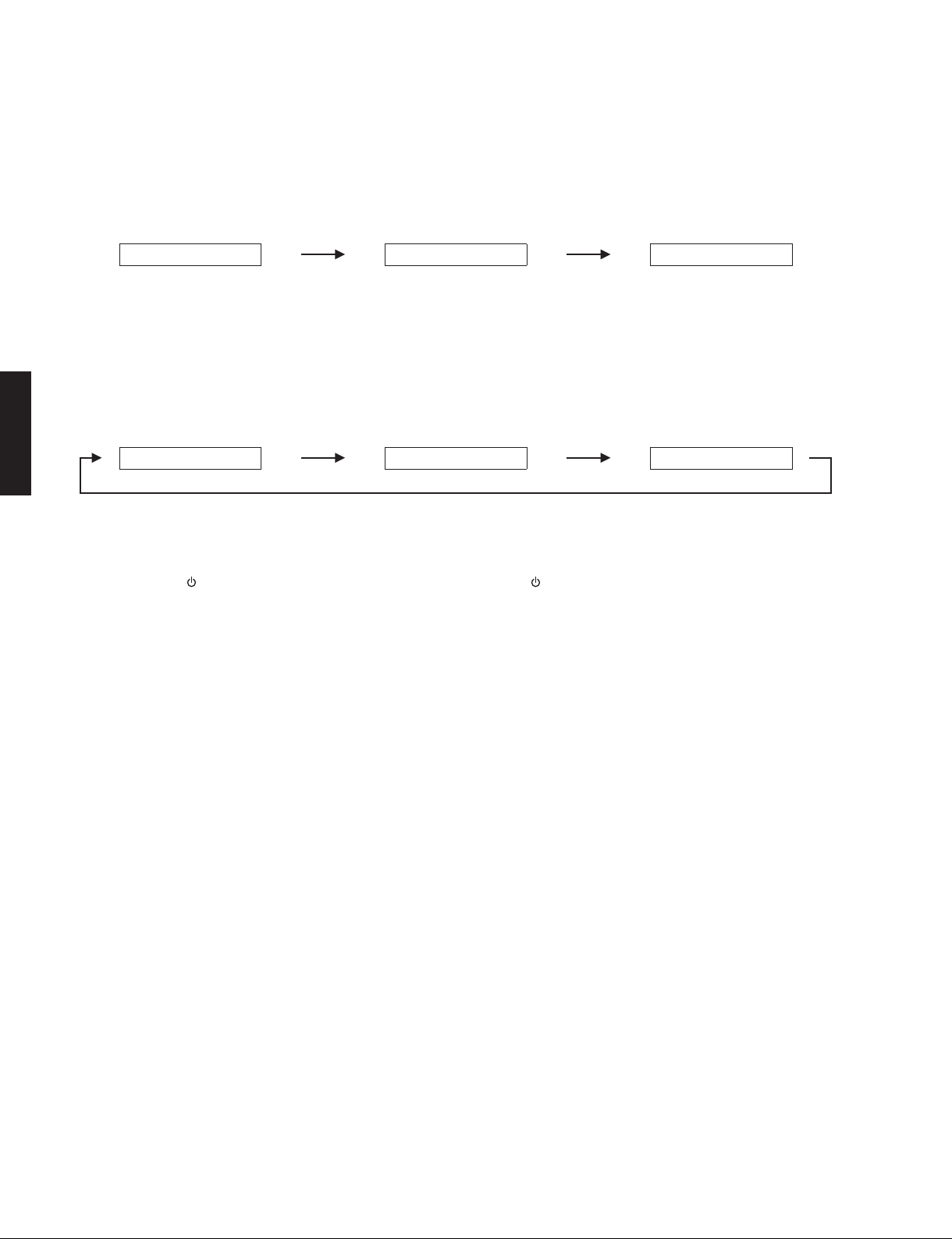
3. The USB UPDATE mode is activated and “USB
Update” is displayed. Writing of the firmware
starts automatically. (Fig. 2)
Writing is started. /
4. When writing of the firmware is completed,
“Update Success”, “Please...” and “Power Off!”
are displayed repeatedly. (Fig. 3)
Writing is completed. /
RX-V373/HTR-3065
5. Press the “ ” (Power) key to turn off the power.
(Fig. 1)
6. Remove the USB storage device from the USB
jack. (Fig. 1)
7. Start up the self-diagnostic function and check
that the firmware version and checksum are
the same as written ones. (See “Confirmation of
firmware version and checksum”)
書き込み開始
USBUpdate
UpdateSuccess
書き込み完了
VERIFYING...
Fig. 2
Please...
Fig. 3
3. USBUPDATE モードが起動し、“USBUpdate” が表
示されて、ファームウェアの書き込みが自動的に
開始されます。(Fig.2)
Writing being executed. /
書き込み中
Sx-x:xx%
4. ファームウェアの書き込み完了後、“Update
Success”、“Please...”、“PowerOff!” が繰り返し表
示されます。(Fig.3)
PowerOff!
5. “
”(電源)キーを押して電源を切ります。(Fig.1)
6. USB 端子から USB フラッシュメモリーを抜きま
す。(Fig.1)
7. ダイアグを起動し、ファームウェアのバージョン
とチェックサムが、書き込まれたものと同じであ
ることを確認します。(“ファームウェアのバージョ
ンとチェックサムの確認” 参照)
24
UpdatingT model
● Required Tools
• CD, DVD or BD player (with DIGITAL OUTPUT (OPTICAL or COAXIAL) jack)
* The following models can be used as a tool to update the firmware.
CD player: CD-C600/CD-S1000/CD-S2000/CD-S300/CD-S700/CDX-496/CDX-596/CDX-890
DVD player: DV-C6760/DVD-840/DVD-C740/DVD-C750/DVD-C940/DVD-C950/DVD-CX1/DVD-S1200/
DVD-S1800/DVD-S2300(MKII)/DVD-S2700/DVD-S30/DVD-S510/DVD-S520/DVD-S530/DVD-S540/
DVD-S550/DVD-S657/DVD-S700/DVD-S80/DVD-S840
BD player: BD-940/BD-S1065/BD-S1900/BD-S2900/BD-S671
Others: CDR-D651/CDR-HD1000/CDR-HD1300/CDR-HD1500/DV-SL100/CDX-E100/CRX-430/CRX-E150/
RDX-E700
• Optical cable (when OPTICAL jack is used)
• Digital audio pin cable (when COAXIAL jack is used)
• Firmware CD
* Download the latest firmware from the specified download source and create the firmware CD.
RX-V373/HTR-3065
RX-V373/HTR-3065
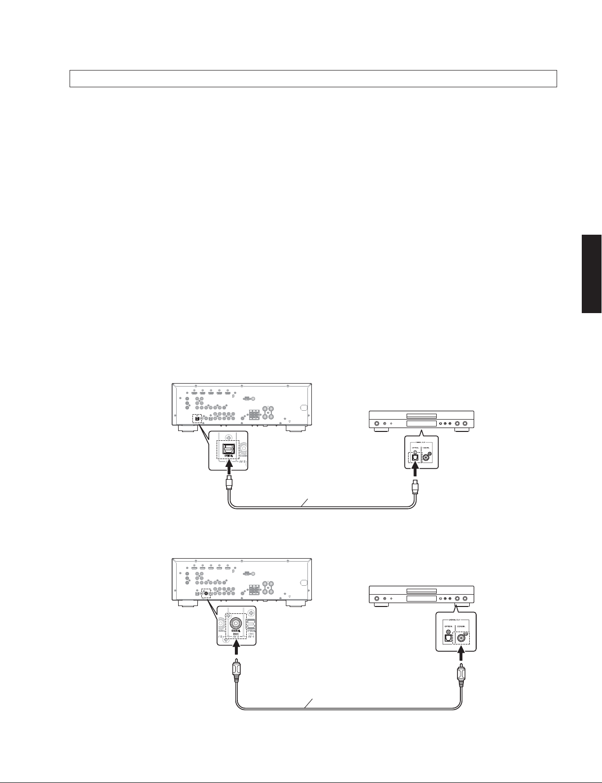
● Connection
Connect a CD/DVD/BD player to this unit as shown below. (Fig. 4)
Example of connection between digital OPTICAL jacks
This unit
Optical cable
Example of connection between digital COAXIAL jacks
This unit
CD/DVD/BD player
CD/DVD/BD player
Digital audio pin cable
Fig. 4
25
RX-V373/HTR-3065
● Operation Procedures
1. While pressing the “MEMORY” key, connect the power cable to the AC outlet. (Fig. 5)
The FIRMWARE UPDATE mode is activated and “CDDA Upgrader” is displayed. (Fig. 5)
RX-V373/HTR-3065
"MEMORY" key
Display
CDDAUpgrader
Fig. 5
2. Play the firmware CD on the CD/DVD/BD player. Writing of the firmware starts automatically. (Fig. 6)
3. When writing of the firmware is completed, “Update Success”, “Please...” and “Power off!!” are displayed
repeatedly. (Fig. 6)
Writing is started Writing is completed
XXXXXXXXXX UpdateSuccess
XXXXXX
: Received data
Please...
Poweroff!!
Fig. 6
* If the display remains unchanged for more than 10 seconds after starting the firmware CD play procedure,
perform the firmware CD play procedure again from the beginning.
4. Press the “
” (Power) key to turn off the power.
5. Eject the firmware CD from the CD/DVD/BD player.
6. Start up the self-diagnostic function and check that the firmware version and checksum are the same as written
ones. (See “Confirmation of firmware version and checksum”)
26
RX-V373/HTR-3065
■ SELF-DIAGNOSTIC FUNCTION /
This unit has self-diagnostic functions that are intended
for inspection, measurement and location of faulty point.
There are 26 main menu items, each of which has submenu items.
Listed in the table below are main menu items and submenu items.
Note: Some of the menu items listed below may not apply
to the models covered in this service manual.
ダイアグ(自己診断機能)
本機には、検査、測定、不良個所の発見を目的にしたダ
イアグ(自己診断機能)があります。
ダイアグには 26 個のメインメニューがあり、そのそれぞ
れにサブメニューがあります。
下表はダイアグメニュー一覧です。
注意: 以下のメニュー項目の一部は、このサービスマニュ
アルに記載されているモデルに適用されない場合
があります。
No. Main menu Sub-menu
1 BYPASS 1 ANALOG BYPASS
2 RAM THROUGH 1 RAM MARGIN
2 RAM FULL ALL
3 RAM FULL CENTER
4 RAM FULL SURROUND
5 RAM FULL SURROUND BACK
(
サービスでは使用しません
Not for service /
6 RAM FULL SUBWOOFER
3 HDMI AUDIO 1 SPDIF
2 Multi
3 DSD
4 ARC
4 SPEAKERS SET 1 FRONT: SML 0dB
2 CENTER: NONE
3 LFE/BASS: FRNT
4 TONE: MAX
5 TONE: MIN
6 SPEAKER 6-ohms
(
サービスでは使用しません
Not for service /
5 LIMITER CONTROL 1 AC_B: Hi
Not for service /
(
サービスでは使用しません
)
2 AC_B: Lo
3 LIM/PLDET/THM
6 MIC CHECK 1 MIC CHECK
(U, C, R, K, A, B, G, F, L, S, H, J models)
7 FL/MONITOR CHECK 1 INITIAL DISPLAY
2 ALL SEGMENT OFF/MONITOR (VIDEO) MUTE
3 ALL SEGMENT ON/MONITOR (COMPONENT) MUTE
4 CHECK PATTERN 1
5 CHECK PATTERN 2
8 MANUAL TEST 1 TEST ALL
9 AD DATA CHECK 1 PS/DC
2 TH1/TH2 (U, C models)
3 TH3
4 AMP
5 K1/K2
10 VIDEO CHECK 1 I2C
2 DIGITAL COMPONENT
3 DIGITAL CVBS
4 DIGITAL Y/C
(
Not for service /
(
Not for service /
(
サービスでは使用しません
サービスでは使用しません
サービスでは使用しません
Not for service /
5 ANALOG BYPASS
RX-V373/HTR-3065
)
)
)
)
)
27
RX-V373/HTR-3065
No. Main menu Sub-menu
11 NO MENU Invalidity
12 NO MENU Invalidity
13 NO MENU Invalidity
14 NO MENU Invalidity
15 HDMI INFORMATION 1 MODEL NAME
16 HDMI SELECT 1 HDMI NONE
17 USB 1 USB FILE 1
(U, C, R, K, A, B, G, F, L, S, H, J models) 2 USB FILE 2
RX-V373/HTR-3065
18 NO MENU Invalidity
19 BUS CHECK 1 TI BUS:
20 NO MENU Invalidity
21 PROTECTION HISTORY 1 HISTORY 1
22 SOFT SWITCH 1 SWITCH MODE
23 UPDATE 1 TI FLASH BOOT
Not for service /
(
24 FACTORY PRESET 1 PRESET INHIBIT
25 ROM VER/SUM/PORT 1 SYSTEM VERSION
26 MODEL/DESTINATION 1 MODEL/DEST
Not for service /
(
サービスでは使用しません
サービスでは使用しません
2 PRODUCT ID
2 HDMI IN 1
3 HDMI IN 2
4 HDMI IN 3
5 HDMI IN 4
3 USB IPL: OK
4 USB iPod CHECK
2 EEPROM:
2 HISTORY 2
3 HISTORY 3
4 HISTORY 4
2 MODEL
3 DESTINATION
)
2 PRESET RESERVED
2 FIRMWARE VERSION
3 ALL CHECKSUM
4 TI (DSP) FLASH ROM VERSION
5 TI (DSP) FLASH ROM CHECKSUM
6 OSD FLASH ROM VERSION
7 OSD FLASH ROM CHECKSUM
8 USB FLASH ROM VERSION
9 USB FLASH ROM CHECKSUM
10 MODEL/DESTINATION
Not for service /
11 Verify
)
2 M/D:
(
サービスでは使用しません
)
28
RX-V373/HTR-3065
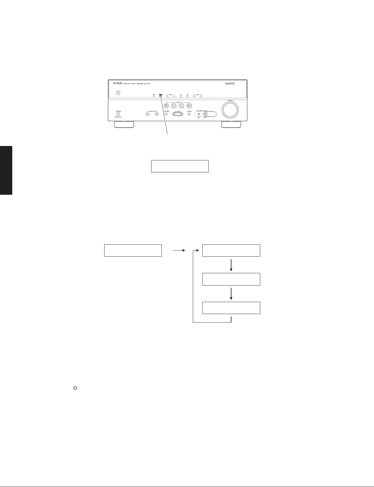
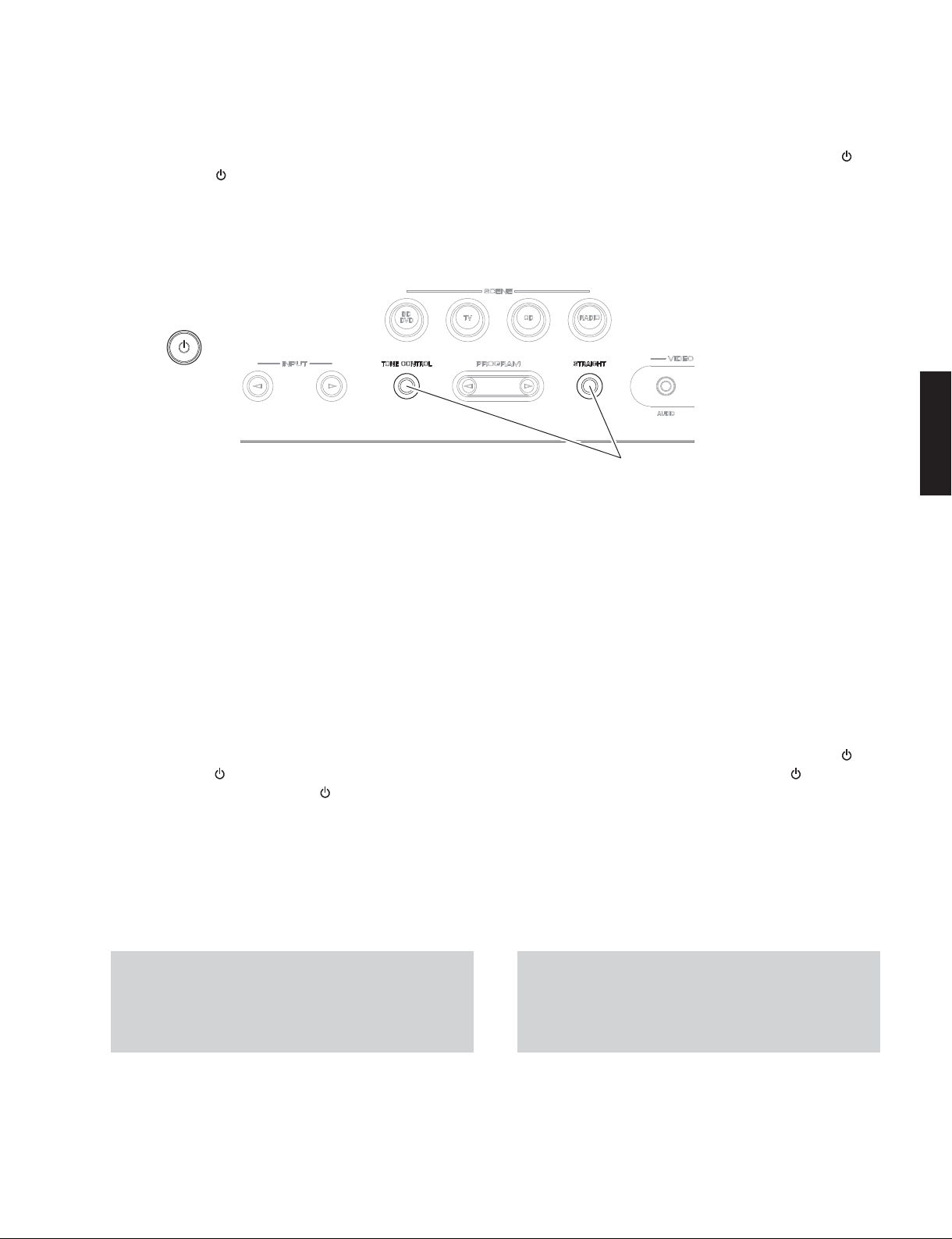
● Starting Self-Diagnostic Function
While pressing the “TONE CONTROL” and “STRAIGHT”
keys, press the “
release those 2 keys.
The self-diagnostic function mode is activated.
(Power)
” (Power) key to turn on the power, and
Keys of this unit /
● ダイアグの起動
“TONECONTROL” と “STRAIGHT” キーを押しながら “ ”(電
源)キーを押して電源を入れた後、2 つのキーを放します。
ダイアグが起動します。
本機キー
RX-V373/HTR-3065
While pressing these keys, turn on the power.
これらのキーを押しながら、電源を入れます。
● Starting Self-Diagnostic Function in
the protection cancel mode
If the protection function works and causes hindrance
to troubleshooting, cancel the protection function by the
procedure below, and it will be possible to enter the selfdiagnostic function mode. (The protection functions other
than the excess current detect function will be disabled.)
While pressing the “TONE CONTROL” and “STRAIGHT”
keys, press the “
keep pressing those 2 keys and “
seconds or longer.
The self-diagnostic function mode is activated with the
protection functions disabled.
In this mode, the “SLEEP” segment of the FL display flashes
to indicate that the mode is self-diagnostic function mode
with the protection functions disabled.
CAUTION!
Using this unit with the protection function disabled may
cause further damage to this unit. Use special care for
this point when using this mode.
” (Power) key to turn on the power and
” (Power) key for 3
●プロテクション解除モードでの起動
プロテクションが動作することにより、故障箇所の診断
に支障をきたすような場合は、次の方法によりプロテク
ションを解除した状態でダイアグモードに入ることがで
きます。(過電流検出以外のプロテクション動作を解除す
る)
“TONECONTROL” と “STRAIGHT” キーを押しながら “
源)キーを押して電源を入れ、2 つのキーと “
を 3 秒以上押し続けます。
プロテクション解除モードでダイアグが起動します。
このモードでは FL の “SLEEP” セグメントが点滅し、プロ
テクションを解除した状態でのダイアグモードであるこ
とを知らせます。
注意!
プロテクションを解除した状態でのダイアグモードは、
危険な状態でもプロテクションが作動しないため、動作
させると、本機を破壊することがあります。このモード
を使用する場合は十分注意してください。
”(電源)キー
”(電
29

RX-V373/HTR-3065
● Canceling Self-Diagnostic Function
1. Before canceling self-diagnostic function, execute
setting for “24. FACTORY PRESET” menu. (Memory
initialization inhibited or Memory initialized).
* In order to keep the user memory preserved, be
sure to select PRESET INHIBIT (Memory initialization
inhibited).
2. Press the “
● Display provided when Self-Diagnostic
Function started
The display is as described below depending on the
situation when the power to this unit is turned off.
RX-V373/HTR-3065
1. When the power is turned off by usual operation:
“NO PROTECT” is displayed. Then “1. ANALOG
BYPASS” is displayed in a few seconds.
” (Power) key to turn off the power.
● ダイアグの解除
1. ダイアグを解除する前に、“24. FACTORYPRESET” メ
ニュー(メモリーの初期化禁止/またはメモリーの
初期化)の設定をします。
※ ユーザーメモリーを保持したい場合は、必ず
PRESETINHIBIT(メモリー初期化禁止)を選択し
てください。
2. “
”(電源)キーを押して電源を切ります。
● ダイアグ起動時の表示
本機の電源が切れたときの状況により、下記のように表
示されます。
1. 通常の操作で電源を切った場合:
“NOPROTECT” が表示されます。数秒後、“1.ANALOG
BYPASS” が表示されます。
Opening message /
NOPROTECT 1.ANALOGBYPAS
オープニング表示
After a few seconds /
Main menu display /
数秒後
メインメニュー表示
30
 Loading...