

Yamaha RX-N600 User Manual

RX-N600
AV Receiver
Ampli-tuner audio-vidéo
G
OWNER’S MANUAL
MODE D’EMPLOI
BEDIENUNGSANLEITUNG
BRUKSANVISNING
GEBRUIKSAANWIJZING
ИНСТРУКЦИЯ ПО ЭКСПЛУАТАЦИИ

CAUTION: READ THIS BEFORE OPERATING YOUR UNIT.
CAUTION: READ THIS BEFORE OPERATING YOUR UNIT.
1 To assure the finest performance, please read this manual
carefully. Keep it in a safe place for future reference.
2 Install this sound system in a well ventilated, cool, dry, clean
place – away from direct sunlight, heat sources, vibration,
dust, moisture, and/or cold. Allow ventilation space of at
least 30 cm on the top, 20 cm on the left and right, and 20
cm on the back of this unit.
3 Locate this unit away from other electrical appliances,
motors, or transformers to avoid humming sounds.
4 Do not expose this unit to sudden temperature changes from
cold to hot, and do not locate this unit in an environment
with high humidity (i.e. a room with a humidifier) to prevent
condensation inside this unit, which may cause an electrical
shock, fire, damage to this unit, and/or personal injury.
5 Avoid installing this unit where a foreign object may fall
onto this unit and/or this unit may be exposed to liquid
dripping or splashing. On the top of this unit, do not place:
– other components, as they may cause damage and/or
discoloration on the surface of this unit.
– burning objects (i.e. candles), as they may cause fire,
damage to this unit, and/or personal injury.
– containers with liquid in them, as they may fall and
liquid may cause electrical shock to the user and/or
damage to this unit.
6 Do not cover this unit with a newspaper, tablecloth, curtain,
etc. in order not to obstruct heat radiation. If the temperature
inside this unit rises, it may cause fire, damage to this unit,
and/or personal injury.
7 Do not plug in this unit to a wall outlet until all connections
are complete.
8 Do not operate this unit upside-down. It may overheat,
possibly causing damage.
9 Do not use force on switches, knobs and/or cords.
10 When disconnecting the power cable from the wall outlet,
grasp the plug; do not pull the cord.
11 Do not clean this unit with chemical solvents; this might
damage the finish. Use a clean, dry cloth.
12 Only voltage specified on this unit must be used. Using this
unit with a higher voltage than specified is dangerous and
may cause fire, damage to this unit, and/or personal injury.
YAMAHA will not be held responsible for any damage
resulting from use of this unit with a voltage other than
specified.
13 To prevent damage by lightning, keep the power cable and
outdoor antennas disconnected from a wall outlet or this unit
during a lightning storm.
14 Do not attempt to modify or fix this unit. Contact qualified
YAMAHA service personnel when any service is needed.
The cabinet should never be opened for any reasons.
15 When not planning to use this unit for long periods of time
(i.e. vacation), disconnect the AC power plug from the wall
outlet.
16 Install this unit near the AC wall outlet where the power
cable plug can be reached easily.
17 Be sure to read the “TROUBLESHOOTING” section on
common operating errors before concluding that this unit is
faulty.
18 Before moving this unit, press MASTER ON/OFF to release
it outward to the OFF position to turn off this unit, and then
disconnect the power cable from the AC wall outlet.
19 VOLTAGE SELECTOR (General model only)
The VOLTAGE SELECTOR on the rear panel of this unit
must be set for your local main voltage BEFORE plugging
into the AC wall outlet.
Voltages are 110/120/220/230–240 V AC, 50/60 Hz.
WARNING
TO REDUCE THE RISK OF FIRE OR ELECTRIC
SHOCK, DO NOT EXPOSE THIS UNIT TO RAIN
OR MOISTURE.
This unit is not disconnected from the AC power
source as long as it is connected to the wall outlet, even
if this unit itself is turned off. In this state, this unit is
designed to consume a very small quantity of power.

CONTENTS
INTRODUCTION
FEATURES............................................................. 2
GETTING STARTED............................................ 3
Supplied accessories .................................................. 3
Installing batteries in the remote control ................... 3
CONTROLS AND FUNCTIONS ......................... 4
Front panel ................................................................. 4
Remote control........................................................... 6
Front panel display .................................................... 9
Rear panel ................................................................ 11
PREPARATION
CONNECTIONS .................................................. 12
Placing speakers....................................................... 12
Connecting speakers ................................................ 13
Information on jacks and cable plugs ...................... 16
Audio and video signal flow.................................... 17
Connecting a TV...................................................... 18
Connecting a DVD player, a DVD recorder,
a VCR or an STB................................................. 19
Connecting a CD player, an MD player
or a tape deck....................................................... 21
Connecting a YAMAHA iPod universal dock ........22
Connecting the network........................................... 23
Connecting a multi-format player,
an external decoder or a sound processor............ 24
Connecting a game console, a video camera
or a portable audio player.................................... 24
Connecting the FM and AM antennas ..................... 25
Connecting the power cable..................................... 26
Setting the speaker impedance................................. 27
Turning on and off the power .................................. 28
BASIC SETUP ...................................................... 29
BASIC OPERATION
PLAYBACK.......................................................... 32
USING AUDIO FEATURES ............................... 34
Using SILENT CINEMA ........................................ 34
Muting the audio output........................................... 34
Selecting the night listening mode........................... 34
Selecting the input mode ......................................... 35
Using the sleep timer ............................................... 35
Adjusting the speaker level...................................... 36
Selecting the Compressed Music Enhancer mode... 37
Selecting the MULTI CH INPUT component......... 38
Enjoying multi-channel sources in 2-channel stereo ....39
Enjoying unprocessed input sources........................ 39
Enjoying pure hi-fi stereo sound.............................. 39
USING VIDEO FEATURES ............................... 40
Displaying the input source information ................. 40
Selecting the OSD mode.......................................... 41
Playing video sources in the background ................ 41
ENJOYING SURROUND SOUND .................... 42
Enjoying multi-channel sources
in 6.1-channel surround ....................................... 42
Enjoying 2-channel sources in surround.................. 43
Using Virtual CINEMA DSP .................................. 44
RECORDING ....................................................... 45
FM/AM TUNING..................................................46
Automatic tuning ..................................................... 46
Manual tuning.......................................................... 47
Automatic preset tuning........................................... 48
Manual preset tuning ............................................... 49
Selecting preset stations........................................... 50
Exchanging preset stations ...................................... 51
RADIO DATA SYSTEM TUNING
(EUROPE MODEL ONLY).............................53
Selecting the Radio Data System program .............. 53
Using the Radio Data System station network ........ 54
Displaying the Radio Data System information ...... 55
SOUND FIELD PROGRAMS
SOUND FIELD PROGRAMS .............................57
Selecting sound field programs ............................... 57
Sound field program descriptions ............................ 58
Changing sound field parameter settings................. 60
ADVANCED OPERATION
SET MENU ............................................................66
Using SET MENU................................................... 68
1 SOUND MENU.................................................... 69
2 INPUT MENU...................................................... 74
3 NET/USB MENU................................................. 76
4 OPTION MENU................................................... 78
ADVANCED SETUP ............................................81
REMOTE CONTROL FEATURES ...................84
Controlling this unit, a TV, or other components.... 84
Setting the remote control code ............................... 86
Setting library codes ................................................ 87
Resetting all remote control codes........................... 88
USING MULTI-ZONE CONFIGURATION .....89
Connecting Zone 2................................................... 89
Controlling Zone 2................................................... 90
USING iPod®.........................................................92
Controlling iPod ...................................................... 92
USING NETWORK/USB FEATURES...............94
Navigating the network and USB menus ................ 94
Using a PC server or YAMAHA
MCX-2000........................................................... 96
Using the Internet radio ........................................... 97
Using a USB memory device or
a USB portable audio player ............................... 98
RESETTING THE SYSTEM...............................99
ADDITIONAL INFORMATION
TROUBLESHOOTING .....................................100
GLOSSARY.........................................................107
Audio information ................................................. 107
Video information.................................................. 109
Sound field program information .......................... 109
SPECIFICATIONS.............................................110
PREPARATIONINTRODUCTION
OPERATION
BASIC
SOUND FIELD
PROGRAMS
OPERATION
ADVANCED
INFORMATION
ADDITIONAL
English
1 En

FEATURES
®
“iPod” i
“S
FEATURES
Built-in 6-channel power amplifier
◆ Minimum RMS output power
(20 Hz to 20 kHz, 0.06% THD, 8 Ω)
Front: 95 W + 95 W
Center: 95 W
Surround: 95 W + 95 W
Surround back: 95 W
Sound field programs
◆ Proprietary YAMAHA technology for the creation of sound
fields
◆ Dolby Digital/Dolby Digital EX decoder
◆ DTS/DTS-ES Matrix 6.1, Discrete 6.1, DTS Neo:6,
DTS 96/24 decoder
◆ Dolby Pro Logic/Dolby Pro Logic II/
Dolby Pro Logic IIx decoder
◆ Virtual CINEMA DSP
◆ SILENT CINEMA
™
Sophisticated AM/FM tuner
◆ 40-station random and direct preset tuning
◆ Automatic preset tuning
◆ Preset station shifting capability (preset editing)
Radio Data System
(Europe model only)
◆ Radio Data System tuning capability
iPod controlling capability
◆ DOCK terminal to connect a YAMAHA iPod universal dock
(such as YDS-10 sold separately), which supports iPod (Click
and Wheel), iPod nano, and iPod mini
Network features
◆ LAN port to connect a PC and YAMAHA MCX-2000 or
access the Internet radio via a LAN
◆ DHCP automatic or manual network configuration
USB features
◆ USB port to connect a USB memory device or a USB portable
audio player
Other features
◆ 192-kHz/24-bit D/A converter
◆ OSD (on-screen display) menus that allow you to optimize
this unit to suit your individual audiovisual system
◆ 6 additional input jacks for discrete multi-channel input
◆ S-video signal input/output capability
◆ Component video input/output capability
(3 COMPONENT VIDEO INs and 1 MONITOR OUT)
◆ Digital video signal conversion (composite video ↔
S-video → component video) capability for monitor out
◆ Optical and coaxial digital audio signal jacks
◆ Sleep timer
◆ Cinema and music night listening modes
◆ Remote control with preset remote control codes,
backlighting input selector buttons, and an iPod (stationed in a
YAMAHA iPod universal dock connected to the DOCK
terminal) controlling capability
◆ Zone 2 custom installation facility
◆ Zone switching capability between the main zone and Zone 2
using ZONE CONTROL
◆ Compressed Music Enhancer mode to improve the sound
quality of compression artifacts (such as the MP3 format) to
that of a high-quality stereo
Manufactured under license from Dolby
Laboratories.
“Dolby”, “Pro Logic”, and the double-D
symbol are trademarks of Dolby
Laboratories.
Manufactured under license from Digital
Theater Systems, Inc. “DTS”, “DTS-ES”,
“NEO:6”, and “DTS 96/24” are trademarks
of Digital Theater Systems, Inc. Copyright
1996, 2003 Digital Theater Systems, Inc. All
right reserved.
iPod
MPEG Layer-3 audio coding technology licensed from
Fraunhofer IIS and Thomson.
2 En
s a trademark of Apple Computer,
Inc., registered in the U.S. and other
countries.
This unit contains programs licensed under the GNU General
Public License and GNU Lesser General Public License.
Windows XP, Windows Media Audio, Windows Media Connect
are either registered trademarks or trademarks of Microsoft
corporation in the United States and/or countries.
This receiver supports network connections.
ILENT CINEMA” is a trademark of
YAMAHA CORPORATION.
GETTING STARTED
Supplied accessories
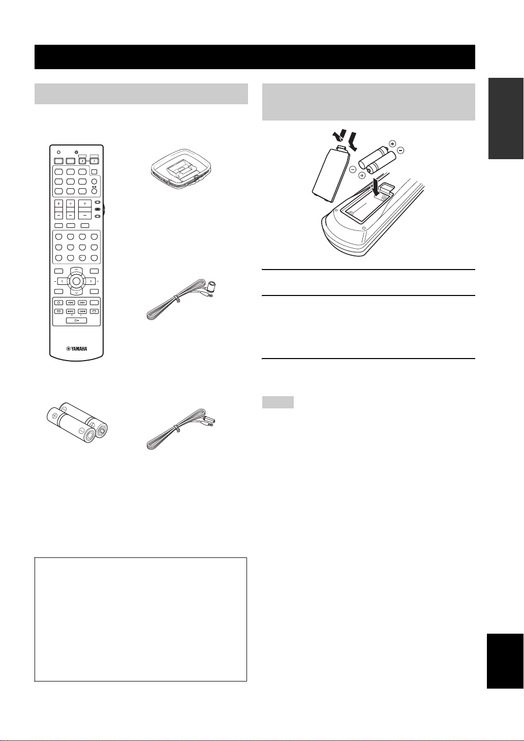
Check that you received all of the following parts.
GETTING STARTED
INTRODUCTION
Installing batteries in the remote control
Remote control
TRANSMITCODE SET
STANDBY
POWER
POWERPOWER
AVTV
SLEEP
MD
CD-R
CD
DVD DTV
DOCK USB
V-AUX DVR
TV VOL TV CH
TV MUTE TV INPUT
STEREO
1
STANDARD
5
SPEAKERS
9
LEVEL
BAND
REC
PC/MCX
FREQ/TEXT EONSTARTPTY SEEKMODE
CBL
MUSIC
SELECT
ENHANCER
NET RADIO
MULTI CH IN
TUNER
NET
AMP
SOURCE
VOLUME
TV
MUTE
ENTERTAIN
MOVIE
2
3
4
EXTD SUR.
DIRECT ST.
6
7
8
NIGHT
STRAIGHT
0
10
ENT.
EFFECT
PRESET/CH
SET MENU
MENUTITLE
SRCH MODE
ENTER
A/B/C/D/E
DISPLAYRETURN
ON SCREENDAB MEMORY
AUDIO
USB
Batteries (2)
(AA, R6, UM-3)
AM loop antenna
Indoor FM antenna
(U.S.A., Canada, China
and General models)
Indoor FM antenna
(Europe, Australia and
Korea models)
About this manual
• y indicates a tip for your operation.
• Some operations can be performed by using either the
buttons on the front panel or the ones on the remote control.
In case the button names differ between the front panel and
the remote control, the button name on the remote control is
given in parentheses.
• This manual is printed prior to production. Design and
specifications are subject to change in part as a result of
improvements, etc. In case of differences between the
manual and product, the product has priority.
1
3
2
1 Take off the battery compartment cover.
2 Insert the two supplied batteries
(AA, R6, UM-3) according to the polarity
markings (+ and –) on the inside of the
battery compartment.
3 Snap the battery compartment cover back
into place.
Notes
• Change all of the batteries if you notice the following
conditions:
– the operation range of the remote control decreases.
– the TRANSMIT indicator does not flash or its light becomes
dim.
• Do not use an old battery together with a new one.
• Do not use different types of batteries (such as alkaline and
manganese batteries) together. Read the packaging carefully as
these different types of batteries may have the same shape and
color.
• If the batteries have leaked, dispose of them immediately. Avoid
touching the leaked material or letting it come into contact with
clothing, etc. Clean the battery compartment thoroughly before
installing new batteries.
• Do not throw away batteries with general house waste; dispose
of them correctly in accordance with your local regulations.
• If the remote control is without batteries for more than 2
minutes, or if exhausted batteries remain in the remote control,
the contents of the memory may be cleared. When the memory
is cleared, insert new batteries and set up the remote control
code that may have been cleared.
English
3 En
CONTROLS AND FUNCTIONS
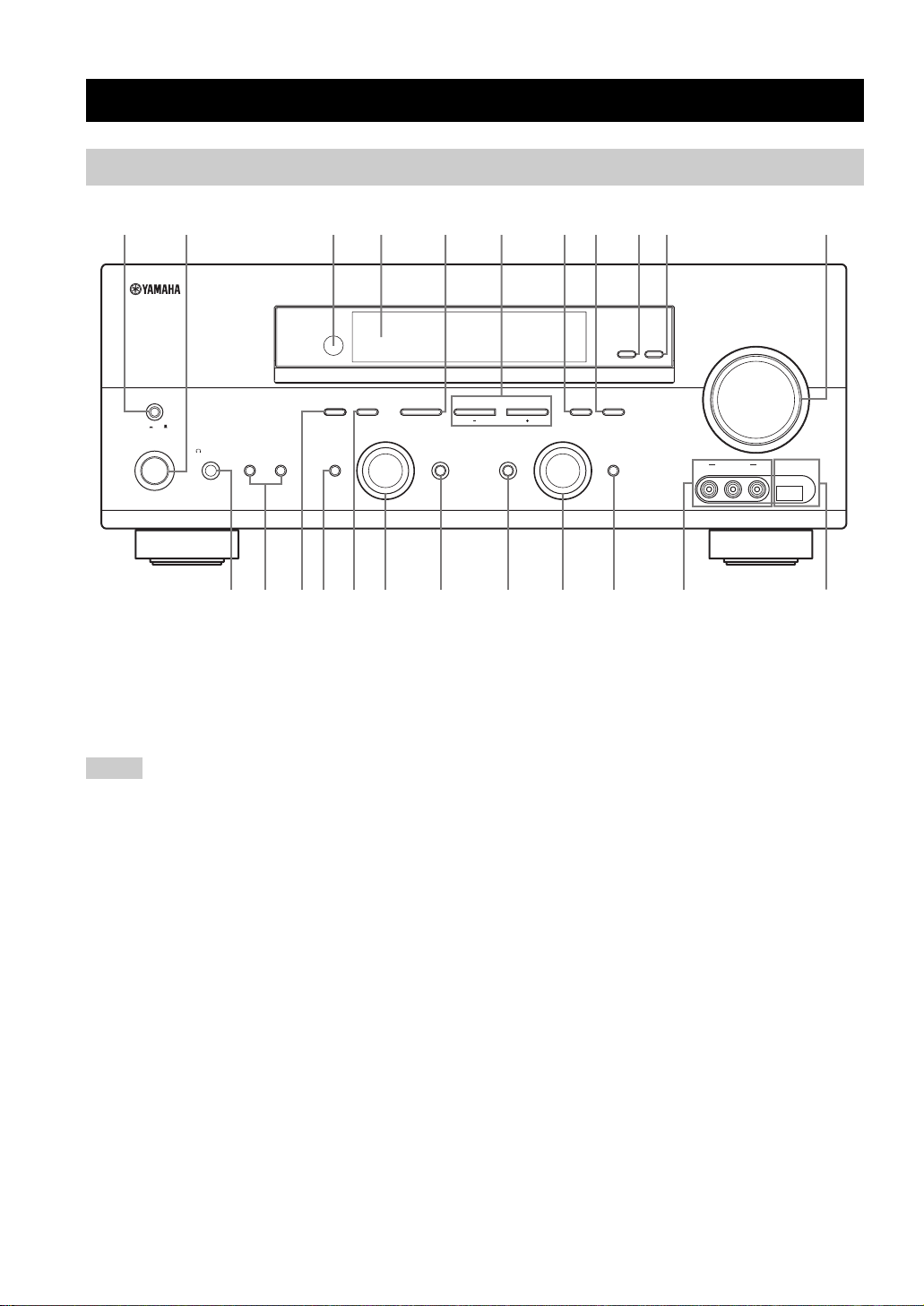
Front panel
CONTROLS AND FUNCTIONS
3145687
MASTER
ON OFF
MAIN ZONE
ON/OFF
SILENT CINEMA
SPEAKERSPHONES
BA
PRESET/TUNING
EFFECT
FM/AM
A/B/C/D/E
NEXTEDIT
PROGRAM
BC2EH
1 MASTER ON/OFF
Turns on or off this unit (see page 28).
2 MAIN ZONE ON/OFF
Turns on the main zone or sets it to the standby mode
(see page 28).
90
VIDEO L AUDIO R
VOLUME
USBVIDEO AUX
ZONE 2
ZONE
ON/OFF
CONTROL
MEMORY
l PRESET/TUNING h
LEVEL
INPUT MODETONE CONTROLSTRAIGHT
IJKGFD
TUNING MODE
MAN'L/AUTO FM
AUTO/MAN'L
INPUT
MULTI CH
INPUT
L
5 A/B/C/D/E, NEXT
• Selects one of the 5 preset station groups (A to E) when
“TUNER” is selected as the input source (see page 49).
• Selects the speaker channel whose output level you
want to adjust when “TUNER” is not selected as the
input source (see page 36).
A
M
Notes
• In the standby mode, this unit consumes a small amount of
power in order to receive infrared signals from the remote
control.
• When you turn on this unit, there will be a 4 to 5-second delay
before this unit can reproduce sound.
• This button is operational only when MASTER ON/OFF is
pressed inward to the ON position.
3 Remote control sensor
Receives signals from the remote control (see page 8).
4 Front panel display
Shows information about the operational status of this unit
(see page 9).
4 En
6 PRESET/TUNING l / h, LEVEL +/–
• Selects one of the 8 preset station numbers (1 to 8)
when “TUNER” is selected as the input source. The
colon (:) is displayed in the front panel display (see
page 50).
• Selects the tuning frequency when “TUNER” is
selected as the input source. The colon (:) is not
displayed in the front panel display (see page 46).
• Adjusts the level of the speaker channel selected using
NEXT when “TUNER” is not selected as the input
source (see page 36).
7 MEMORY (MAN’L/AUTO FM)
Stores a preset station in the memory. Hold down this
button for more than 3 seconds to start automatic preset
tuning (see page 48).

CONTROLS AND FUNCTIONS
8 TUNING MODE (AUTO/MAN’L)
Switches between automatic tuning (the AUTO indicator
is turned on) and manual tuning (the AUTO indicator is
turned off) (see page 46).
9 ZONE 2 ON/OFF
Turns on Zone 2 or sets it to the standby mode
(see page 90).
Note
This button is operational only when MASTER ON/OFF is
pressed inward to the ON position.
0 ZONE CONTROL
Switches the zone you want to control between the main
zone and Zone 2 (see page 90).
y
When Zone 2 is selected, the ZONE2 indicator flashes in the front
panel display for approximately 5 seconds. While the indicator is
flashing, perform the desired operation.
A VOLUME
Controls the output level of all audio channels.
y
This does not affect the AUDIO OUT (REC) level.
B PHONES (SILENT CINEMA) jack
Outputs audio signals for private listening with
headphones (see page 34).
Notes
• When you connect headphones, no signals are output at the
SUBWOOFER OUTPUT jack or the speaker terminals.
• All Dolby Digital and DTS audio signals are mixed down to the
left and right headphone channels.
C SPEAKERS A/B
Turns on or off the set of front speakers connected to the
FRONT A and/or B terminals on the rear panel each time
the corresponding button is pressed.
D PRESET/TUNING, EDIT
• Switches the function of PRESET/TUNING l / h
between selecting preset station numbers and selecting
the tuning frequency.
• Edits the assignments of preset stations (see page 51).
E STRAIGHT (EFFECT)
Turns the sound field programs off or on. When the
“STRAIGHT” mode is selected, 2-channel or multichannel input signals are output directly from their
respective speakers without effect processing (see
page 39).
F FM/AM
Switches the reception band between FM and AM when
“TUNER” is selected as the input source (see page 46).
G PROGRAM selector
Selects sound field programs or adjusts the bass/treble
balance in conjunction with TONE CONTROL (see
page 33).
H TONE CONTROL
Adjusts the bass/treble balance of the front left and right
speakers in conjunction with the PROGRAM selector
(see page 33).
I INPUT MODE
Selects either digital or analog input signals exclusively or
sets this unit to automatically detect the type of input
signals and select the corresponding input signals when
one component is connected via both digital and analog
connections (see page 35).
J INPUT selector
Selects the desired input source.
K MULTI CH INPUT
Selects the component connected to the MULTI CH
INPUT jacks as the input source (see page 38).
Note
The input source connected to the MULTI CH INPUT jacks takes
priority over the source selected with the INPUT selector on the
front panel (or the input selector buttons on the remote control).
L VIDEO AUX jacks
Input audio and video signals from a portable external
source such as a game console, a video camera or a
portable audio player (see page 24).
y
To reproduce the source signals input at these jacks, select
“V-AUX” as the input source.
INTRODUCTION
Note
The audio signals input at the DOCK terminal on the rear panel
take priority over the ones input at the VIDEO AUX jacks.
M USB port
Use to connect a USB memory device or a USB portable
audio player (see page 98).
5 En
English
CONTROLS AND FUNCTIONS
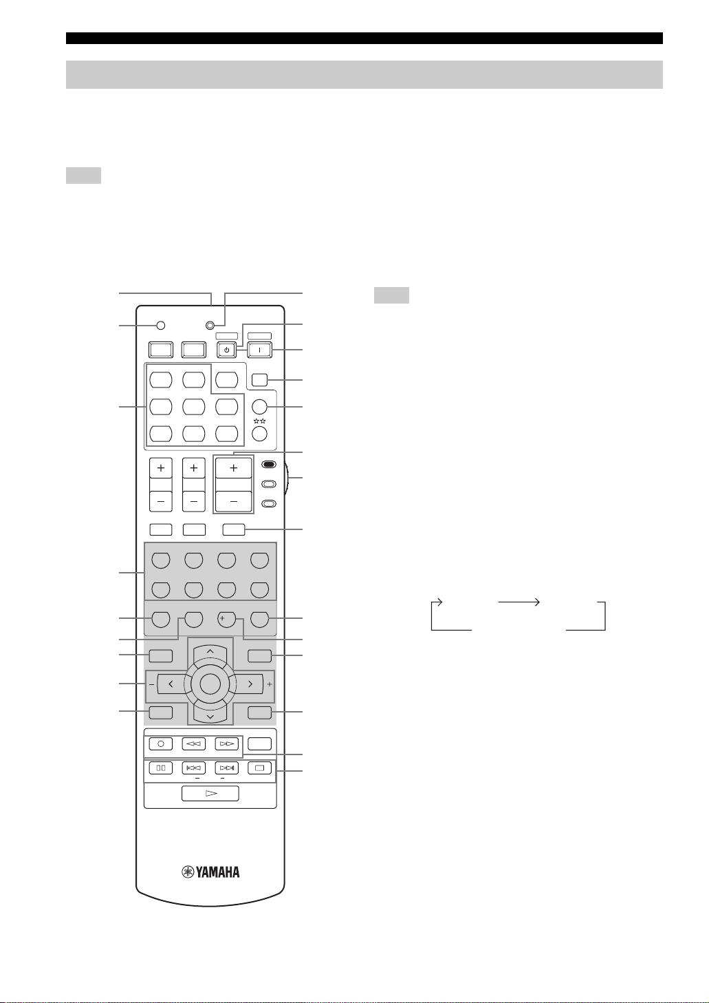
Remote control
This section describes the function of each control on the
remote control used to control this unit. To operate other
components, see “REMOTE CONTROL FEATURES” on
page 84.
Note
The operation mode of the remote control buttons in the shaded
area below depends on the component selector switch position.
Set the component selector switch to AMP to control this unit. To
control the TUNER functions, set the component selector switch
to SOURCE and then press TUNER to select “TUNER” as the
input source.
1
2
3
TRANSMITCODE SET
STANDBY
POWERPOWER
AVTV
MD
CD-R
CD
CBL
DVD DTV
DOCK USB
V-AU X DVR
TV VOL TV CH
TUNER
NET
VOLUME
POWER
SLEEP
MULTI CH IN
SOURCE
AMP
0
A
B
C
D
E
F
TV
■ Controlling this unit
Set the component selector switch to AMP to control this
unit.
1 Infrared window
Outputs infrared control signals. Aim this window at the
component you want to operate (see page 8).
2 CODE SET
Use to set up remote control codes (see page 86).
3 Input selector buttons
Select the input source you want to control.
Note
The corresponding input selector button for the currently selected
input source lights up for approximately 5 seconds after you press
any buttons on the remote control, showing which source
component is currently being operated.
4 Sound field program selector buttons
Select sound field programs (see page 57).
– Use SELECT to play back 2-channel sources in
surround (see page 43).
– Use EXTD SUR. to switch between 5.1 and
6.1-channel playback of multi-channel sources
(see page 42).
– Use DIRECT ST. to play back 2-channel sources in
hi-fi stereo sound (see page 39).
4
5
6
7
8
9
TV MUTE TV INPUT
STEREO
1
STANDARD
5
SPEAKERS
ENHANCER
9
LEVEL
BAND
REC
NET RADIO
PC/MCX
FREQ/TEXT EONSTARTPTY SEEKMODE
MUSIC
2
SELECT
6
0
ENTERTAIN
EXTD SUR.
PRESET/CH
ENTER
NIGHT
USB
MUTE
3
7
10
MOVIE
DIRECT ST.
STRAIGHT
EFFECT
SET MENU
MENUTITLE
SRCH MODE
A/B/C/D/E
DISPLAYRETURN
ON SCREENDAB MEMORY
AUDIO
G
5 SPEAKERS
Turns on or off the set of front speakers connected to the
4
FRONT A and/or B terminals on the rear panel. Press this
button repeatedly to toggle as follows:
8
ENT.
H
I
J
6 ENHANCER
A on B on
A and B off
Turns on or off the Compressed Music Enhancer mode
(see page 37).
K
7 LEVEL
Selects the speaker channel to be adjusted and sets the
output level (see page 36).
L
M
8 Cursor buttons u / d / j / i, ENTER
Select and adjust the sound field program parameters or
the “SET MENU” parameters.
9 RETURN
Returns to the previous menu level when adjusting the
“SET MENU” parameters.
6 En

CONTROLS AND FUNCTIONS
0 TRANSMIT indicator
Flashes while the remote control is sending infrared
signals.
A STANDBY
Sets this unit to the standby mode (see page 28).
Note
This button is operational only when MASTER ON/OFF on the
front panel is pressed inward to the ON position.
B POWER
Turns on this unit (see page 28).
Note
This button is operational only when MASTER ON/OFF on the
front panel is pressed inward to the ON position.
C SLEEP
Sets the sleep timer (see page 35).
D MULTI CH IN
Selects the component connected to the MULTI CH
INPUT jacks as the input source when using an external
decoder, etc. (see page 38).
E VOLUME +/–
Increases or decreases the volume level.
F Component selector switch
Selects the operation mode of the remote control buttons
in the shaded area.
AMP
Operates this unit.
SOURCE
Operates the component selected with an input
selector button (see page 85).
TV
Operates the TV assigned to either DTV/CBL or
(see page 84).
Notes
• To set the remote control codes for other components, see
page 86.
• When you set the remote control codes for both DTV/CBL and
(see page 86), priority is given to the one set for DTV/
CBL.
G MUTE
Mutes the audio output. Press again to restore the audio
output to the previous volume level (see page 34).
H STRAIGHT (EFFECT)
Turns the sound field programs off or on. When the
“STRAIGHT” mode is selected, 2-channel or multichannel input signals are output directly from their
respective speakers without effect processing (see
page 39).
I NIGHT
Turns on or off the night listening modes (see page 34).
J SET MENU
Enters “SET MENU” (see page 68).
K DISPLAY
Selects the on-screen display (OSD) mode for your video
monitor (see page 41).
L Network and USB input selector buttons
Select the sub input source of NET/USB (see page 94).
PC/MCX
Selects a PC server or YAMAHA MCX-2000 as the
sub input source of NET/USB.
NET RADIO
Selects the Internet radio as the sub input source of
NET/USB.
USB
Selects a USB memory device or a USB portable
audio player as the sub input source of NET/USB.
Notes
• Press NET/USB to select “NET/USB” as the input source
before you press any of the network and USB input selector
buttons stated above to select the corresponding sub input
source of NET/USB.
• When you press any of the network and USB input selector
buttons, the contents previously played for the corresponding
sub input source of NET/USB is automatically played.
M Radio Data System tuning buttons
(Europe model only)
FREQ/TEXT
Switches the Radio Data System display between the
PS mode, PTY mode, RT mode, CT mode (if the
station offers the corresponding data services) and the
frequency display (see page 56).
PTY SEEK MODE
Sets this unit to the PTY SEEK mode (see page 53).
PTY SEEK START
Starts searching for a station once the desired program
type is selected in the PTY SEEK mode (see page 54).
EON
Selects a program type (NEWS, AFFAIRS, INFO, or
SPORT) for automatic tuning (see page 55).
INTRODUCTION
English
7 En
CONTROLS AND FUNCTIONS
■ Controlling the TUNER functions
Set the component selector switch to SOURCE and then
press TUNER to select “TUNER” as the input source.
4 Numeric buttons
Use numbers 1 through 8 to select preset stations.
7 BAND
Switches the reception band between FM and AM.
8 Cursor buttons u / d / j / i
Press j / i to select a preset station group (A to E) and
u / d to select a preset station number (1 to 8)
(see page 50).
Note
The printed letters “DAB MEMORY” and “SRCH MODE” are
not applicable to this unit.
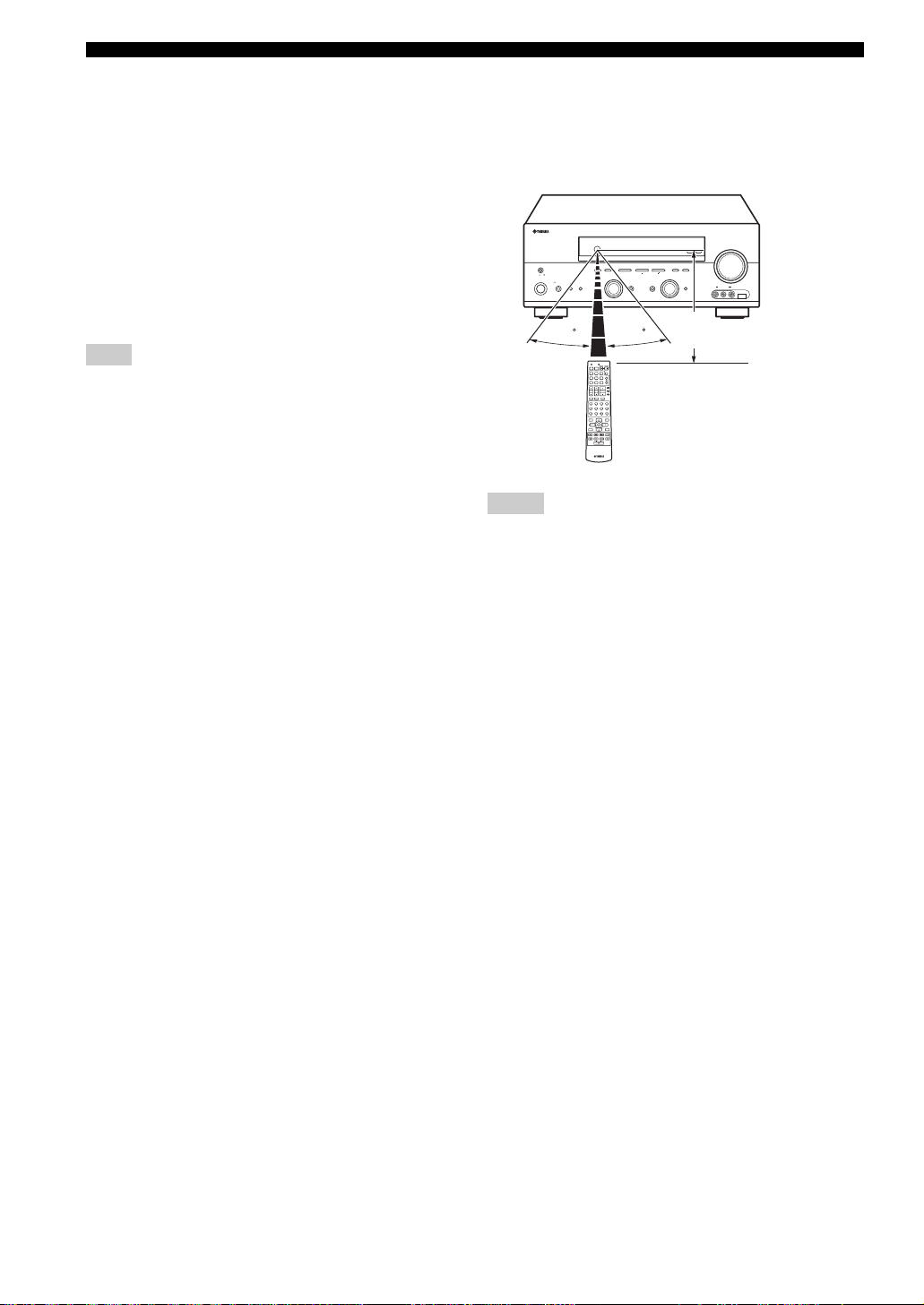
■ Using the remote control
The remote control transmits a directional infrared ray.
Be sure to aim the remote control directly at the remote
control sensor on this unit during operation.
VOLUME
ZONE 2
ZONE
ON/OFF
MASTER
ON OFF
MAIN ZONE
ON/OFF
FM/AM
PRESET/TUNING
A/B/C/D/E
l PRESET/TUNING h
NEXTEDIT
PROGRAM
SPEAKERSPHONES
BA
EFFECT
SILENT CINEMA
30 30
TRANSMITCODE SET
STANDBY
POWER
POWERPOWER
AVTV
SLEEP
MD
CD-R
CD
MULTI CH IN
CBL
DVD DTV
TUNER
DOCK USB
V-AUX DVR
NET
AMP
SOURCE
TV VOL TV CH
VOLUME
TV
TV MUTE TV INPUT
MUTE
STEREO
MUSIC
ENTERTAIN
MOVIE
1
2
3
4
STANDARD
SELECT
EXTD SUR.
DIRECT ST.
5
6
7
8
SPEAKERS
ENHANCER
NIGHT
STRAIGHT
9
0
10
ENT.
EFFECT
PRESET/CH
SET MENU
LEVEL
MENUTITLE
SRCH MODE
BAND
ENTER
A/B/C/D/E
DISPLAYRETURN
ON SCREENDAB MEMORY
REC
AUDIO
USB
NET RADIO
PC/MCX
FREQ/TEXT EONSTARTPTY SEEKMODE
Notes
• Do not spill water or other liquids on the remote control.
• Do not drop the remote control.
• Do not leave or store the remote control in the following types
of conditions:
– places of high humidity, such as near a bath
– places of high temperatures, such as near a heater or stove
– places of extremely low temperatures
– dusty places
CONTROL
MEMORY
TUNING MODE
LEVEL
MAN'L/AUTO FM
AUTO/MAN'L
INPUT
INPUT MODETONE CONTROLSTRAIGHT
MULTI CH
INPUT
VIDEO L AUDIO R
Approximately 6 m
USBVIDEO AUX
8 En
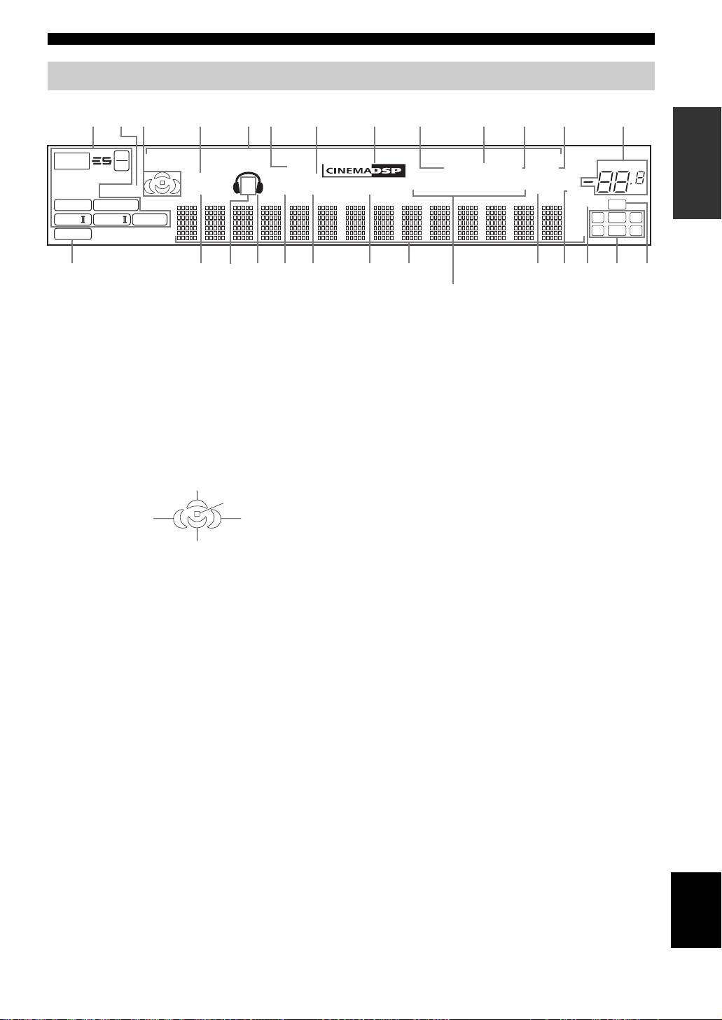
Front panel display
CONTROLS AND FUNCTIONS
2
13 45 768 B
p
NET
t
MATRIX DISCRETE
q EX
q PL x
PCM
96
24
ENHANCER
q
DIGITAL
q PL
q PL
USB
VIRTUAL
STANDARD
D
1 Decoder indicators
The respective indicator lights up when any of the
decoders of this unit functions.
2 ENHANCER indicator
Lights up when the Compressed Music Enhancer mode is
turned on (see page 37).
3 Sound field indicators
Light up to indicate the active DSP sound fields.
p
DVR
p
V-AUXpDTV/CBL
DOCK
SILENT CINEMA
SP
ZONE2 NIGHT
A B
EI
F
H
GJK LNMPO
HiFi DSP
p
DVD
7 SILENT CINEMA indicator
Lights up when headphones are connected and a sound
field program is selected (see page 34).
8 CINEMA DSP indicator
Lights up when you select a CINEMA DSP sound field
program (see page 58).
9 AUTO indicator
Lights up when this unit is in the automatic tuning mode
p
MD/CD-RpTUNER
0A9C
p
EON
CD
MEMORY
SLEEP
MUTE
ft
mS
dB
TUNED
AUTO
Q
STEREO
PTYPTY
PSHOLD RT
CT
(Europe model only)
(see page 46).
Presence DSP sound field
Listening position
Surround left
DSP sound field
Surround back DSP sound field
Surround right
DSP sound field
4 VIRTUAL indicator
Lights up when Virtual CINEMA DSP is active (see
page 44).
5 Input source indicators
The corresponding cursor lights up to show the currently
selected input source.
6 DOCK indicator
Lights up when you station your iPod in a YAMAHA iPod
universal dock (such as YDS-10 sold separately)
0 TUNED indicator
Lights up when this unit is tuned into a station
(see page 46).
A STEREO indicator
Lights up when this unit is receiving a strong signal for an
FM stereo broadcast while the AUTO indicator is lit.
B MEMORY indicator
Flashes to show that a station can be stored (see page 48).
C VOLUME level indicator
Indicates the current volume level.
D PCM indicator
Lights up when this unit is reproducing PCM (Pulse Code
Modulation) digital audio signals.
connected to the DOCK terminal of this unit
(see page 22).
VOLUME
96/24
LFE
LCR
SL SB SR
INTRODUCTION
dB
9 En
English

CONTROLS AND FUNCTIONS
E STANDARD indicator
Lights up when the “SUR. STANDARD” or “SUR.
ENHANCED” program is selected.
F SP A B indicators
Light up according to the set of front speakers selected.
G Headphones indicator
Lights up when headphones are connected.
H ZONE2 indicator
Lights up when Zone 2 is turned on (see page 90).
I NIGHT indicator
Lights up when you select a night listening mode
(see page 34).
J HiFi DSP indicator
Lights up when you select a HiFi DSP sound field
program (see page 59).
K Multi-information display
Shows the name of the current sound field program and
other information when adjusting or changing settings.
L SLEEP indicator
Lights up while the sleep timer is on (see page 35).
M MUTE indicator
Flashes while the MUTE function is on (see page 34).
N 96/24 indicator
Lights up when a DTS 96/24 signal is input to this unit.
O Input channel indicators
Indicate the channel components of the current digital
input signal.
P LFE indicator
Lights up when the input signal contains the LFE signal.
Q Radio Data System indicators
(Europe model only)
The corresponding indicator lights up to show the type
of the Radio Data System information.
EON
Lights up when the EON data service is being
received.
PTY HOLD
Lights up while searching for the Radio Data System
stations in the PTY SEEK mode.
10 En
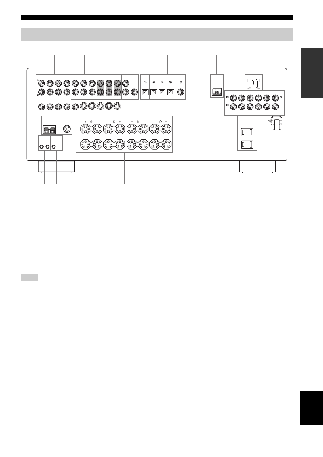
Rear panel
CONTROLS AND FUNCTIONS
AUDIO AUDIO OUTPUT DIGITAL INPUT
IN
CD
(PLAY)
IN OUT
DTV/CBL
DVR DVD DTV/CBL
DVD
VIDEO S VIDEO
TUNER SPEAKERS
AM
ANT
GND
REMOTE CONTROL
+12V
OUTIN
15mA MAX.
MONITOR
OUT
FM ANT
75Ω
UNBAL.
A
OUT
B
ABC
MD/
OUT
CD-R
FRONT ZONE 2
(REC)
MULTI CH INPUT
SURROUND
IN OUT
DVR
FRONT
CENTER
SUB
WOOFER
MONITOR
OUT
DE
WOOFER
SUB
CENTER
DIGITAL
OUTPUT
OPTICAL OPTICAL
SURROUND
1 Video component jacks
See pages 18 and 19 for connection information.
2 Audio component jacks
See page 21 for connection information.
3 MULTI CH INPUT jacks
See page 24 for connection information.
4 ZONE 2 OUTPUT jacks
See page 89 for connection information.
Note
These jacks output analog signals only.
5 SUBWOOFER OUTPUT jack
See page 13 for connection information.
6 DIGITAL OUTPUT jack
See page 21 for connection information.
7 DIGITAL INPUT jacks
See pages 19 and 21 for connection information.
8 DOCK terminal
Use to connect a YAMAHA iPod universal dock (such as
YDS-10 sold separately) where your iPod can be
stationed.
See page 22 for connection information.
9 07654321
LANDOCK
RPBY
P
COMPONENT VIDEO
MONITOR OUT
DVD DVD
SURROUND BACK
8
DTV/CBLMD/CD-RMD/CD-R
COAXIAL
DVD
DTV/
CBL
9 LAN port
Use to connect a network cable for network connections.
See page 23 for connection information.
0 COMPONENT VIDEO jacks
See pages 18 and 19 for connection information.
A REMOTE jacks
See page 89 for details.
B CONTROL OUT jack
This is a control expansion terminal for custom
installation.
C Antenna terminals
See page 25 for connection information.
D Speaker terminals
See page 13 for connection information.
E AC OUTLET(S)
Use to supply power to your other audiovisual
components.
See page 26 for details.
■ VOLTAGE SELECTOR
(General model only)
See page 26 for details.
INTRODUCTION
PRPBY
DVR
11 En
English
CONNECTIONS
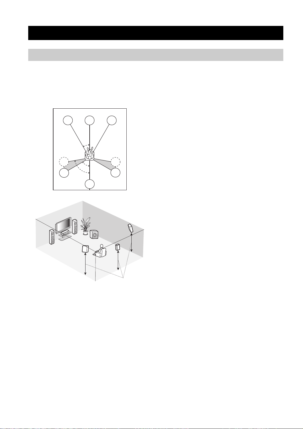
Placing speakers
CONNECTIONS
The speaker layout below shows the standard ITU-R*
speaker setting. You can use it to enjoy CINEMA DSP and
multi-channel audio sources.
*
ITU-R is the radio communication sector of the ITU
(International Telecommunication Union).
FL
SL
SL
C
30˚
60˚
80˚
SB
FR
SR
SR
FR
FL
SW
SR
C
SL
SB
1.8 m (6 ft)
Front left and right speakers (FL and FR)
The front speakers are used for the main source sound plus
effect sounds. Place these speakers at an equal distance
from the ideal listening position. The distance of each
speaker from each side of the video monitor should be the
same.
Center speaker (C)
The center speaker is for the center channel sounds
(dialog, vocals, etc.). If for some reason it is not practical
to use a center speaker, you can do without it. Best results,
however, are obtained with the full system. Place the
center speaker centrally between the front speakers and as
close to the monitor as possible, such as directly over or
under it.
Surround left and right speakers (SL and SR)
The surround speakers are used for effect and surround
sounds. Place these speakers behind your listening
position, facing slightly inwards, about 1.8 m (6 ft) above
the floor.
Surround back speaker (SB)
The surround back speaker supplements the surround
speakers and provides more realistic front-to-back
transitions. Place this speaker directly behind the listening
position and at the same height as the surround speakers.
Subwoofer (SW)
The use of a subwoofer with a built-in amplifier, such as
the YAMAHA Active Servo Processing Subwoofer
System, is effective not only for reinforcing bass
frequencies from any or all channels, but also for high
fidelity reproduction of the LFE (low-frequency effect)
channel included in Dolby Digital and DTS sources. The
position of the subwoofer is not so critical, because low
bass sounds are not highly directional. But it is better to
place the subwoofer near the front speakers. Turn it
slightly toward the center of the room to reduce wall
reflections.
12 En
CONNECTIONS
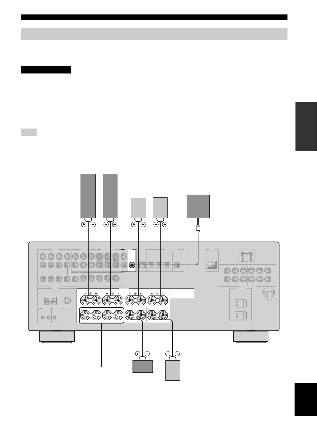
Connecting speakers
Be sure to connect the left channel (L), right channel (R), “+” (red) and “–” (black) properly. If the connections are faulty,
no sound will be heard from the speakers, and if the polarity of the speaker connections is incorrect, the sound will be
unnatural and lack bass.
CAUTION
• Before connecting the speakers, make sure that this unit is turned off (see page 28).
• Do not let the bare speaker wires touch each other or do not let them touch any metal part of this
unit. This could damage this unit and/or speakers.
• Use magnetically shielded speakers. If this type of speakers still creates the interference with the
monitor, place the speakers away from the monitor.
• If you are to use 6 ohm speakers, be sure to set “SP IMP.” to “6ΩMIN” before using this unit (see
page 27). 4 ohm speakers can be also used as the front speakers (see page 82).
Note
A speaker cord is actually a pair of insulated cables running side by side. Cables are colored or shaped differently, perhaps with a stripe,
groove or ridge. Connect the striped (grooved, etc.) cable to the “+” (red) terminals of this unit and your speaker. Connect the plain cable
to the “–” (black) terminals.
Front speakers (A)
LeftRight
PREPARATION
Surround speakers
Subwoofer
LeftRight
1 2 4 57
OUTPUT
SUB
WOOFER
FRONT
A
B
SPEAKERS
CENTER SURROUND BACK
SURROUND
Front
speakers
(B)
Center
speaker
63
Surround back
speaker
English
13 En

CONNECTIONS
FRONT terminals
Connect one or two sets of front speakers (1, 2) to these
terminals. If you use only one front speaker system,
connect it to the FRONT A or B terminal.
CENTER terminals
Connect a center speaker (3) to these terminals.
SURROUND terminals
Connect surround speakers (4, 5) to these terminals.
SURROUND BACK terminals
Connect a surround back speaker (6) to these terminals.
SUBWOOFER OUTPUT jack
Connect a subwoofer with a built-in amplifier (7) (such as
the YAMAHA Active Servo Processing Subwoofer
System) to this jack.
1
7
2
3
5
Speaker layout
4
6
14 En
CONNECTIONS
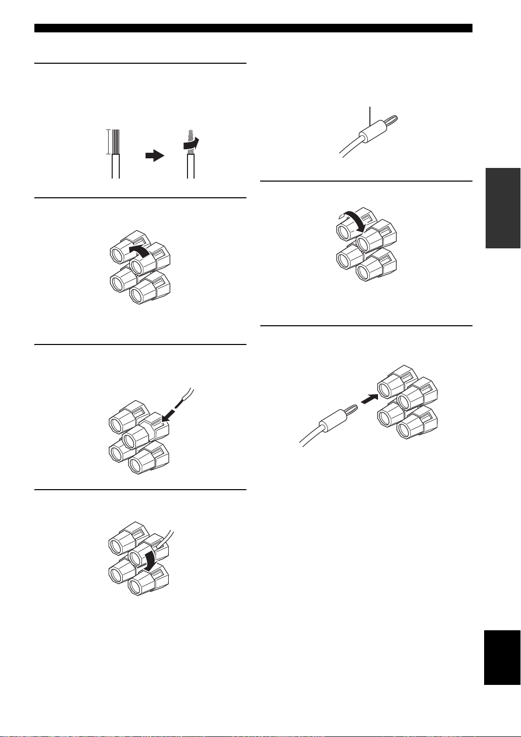
■ Connecting the speaker cable
1 Remove approximately 10 mm of insulation
from the end of each speaker cable and then
twist the exposed wires of the cable together
to prevent short circuits.
10 mm
2 Loosen the knob.
Red: positive (+)
Black: negative (–)
3 Insert one bare wire into the hole on the side
of each terminal.
■ Connecting the banana plug
(except Europe model)
The banana plug is a single-pole electrical connector
widely used to terminate speaker cables.
Banana plug
PREPARATION
1 Tighten the knob.
Red: positive (+)
Black: negative (–)
2 Insert the banana plug connector into the
end of the corresponding terminal.
4 Tighten the knob to secure the wire.
English
15 En
CONNECTIONS
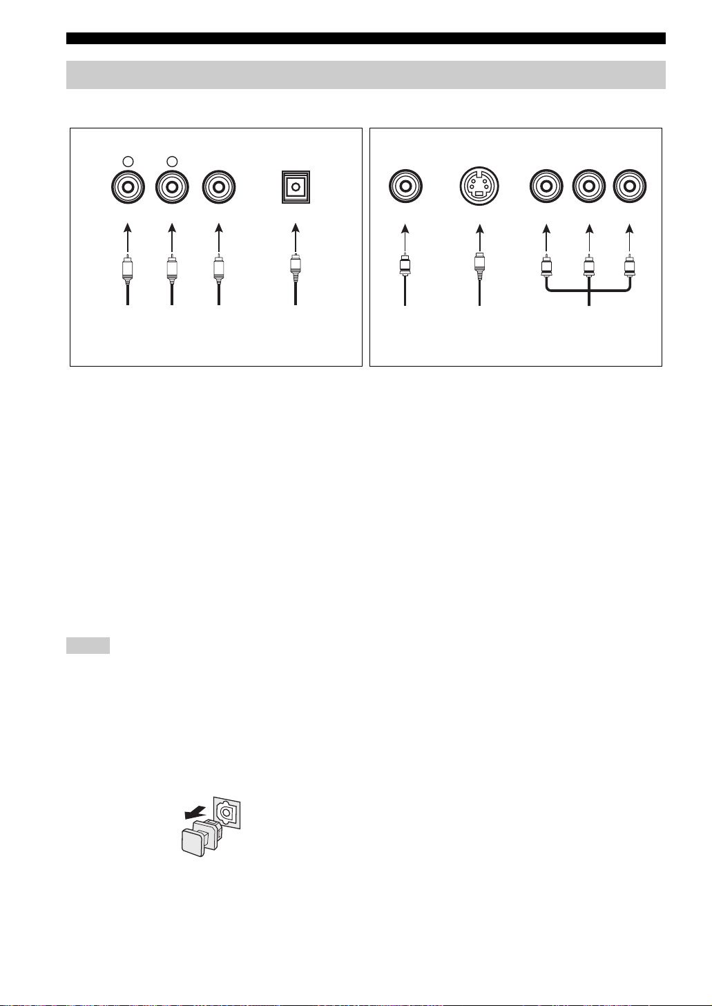
Information on jacks and cable plugs
Audio jacks and cable plugs Video jacks and cable plugs
AUDIO
L
L
Left and right
analog audio
cable plugs
R
(Red)(White) (Orange) (Yellow) (Green) (Blue) (Red)
R
DIGITAL AUDIO
COAXIAL
C
Coaxial
digital audio
cable plug
DIGITAL AUDIO
OPTICAL
O
Optical
digital
audio cable
plug
■ Audio jacks
This unit has three types of audio jacks. Connection
depends on the availability of audio jacks on your other
components.
AUDIO jacks
For conventional analog audio signals transmitted via left
and right analog audio cables. Connect red plugs to the
right jacks and white plugs to the left jacks.
DIGITAL AUDIO COAXIAL jacks
For digital audio signals transmitted via coaxial digital
audio cables.
DIGITAL AUDIO OPTICAL jacks
For digital audio signals transmitted via optical digital
audio cables.
Notes
• You can use the digital jacks to input PCM, Dolby Digital and
DTS bitstreams. When you connect components to both the
COAXIAL and OPTICAL jacks, priority is given to the signals
input at the COAXIAL jack. All digital input jacks are
compatible with 96-kHz sampling digital signals.
• Pull out the cap from the optical jack before you connect the
fiber optic cable. Do not discard the cap. When you are not
using the optical jack, be sure to put the cap back in place. This
cap protects the jack from dust.
VIDEO S VIDEO
V
Composite
video cable
plug
cable plug
S
S-video
COMPONENT VIDEO
Y PBP
PB
Y
Component
video cable
plugs
R
P
R
■ Video jacks
This unit has three types of video jacks. Connection
depends on the availability of input jacks on your video
monitor.
VIDEO jacks
For conventional composite video signals transmitted via
composite video cables.
S VIDEO jacks
For S-video signals, separated into the luminance (Y) and
chrominance (C) video signals transmitted on separate
wires of S-video cables.
COMPONENT VIDEO jacks
For component video signals, separated into the
luminance (Y) and chrominance (P
transmitted on separate wires of component video cables.
y
When “VIDEO CONV.” is set to “ON” (see page 78), the video
signals input at the VIDEO and S VIDEO jacks are converted and
output at the VIDEO, S VIDEO and COMPONENT VIDEO
jacks interchangeably.
B, PR) video signals
16 En
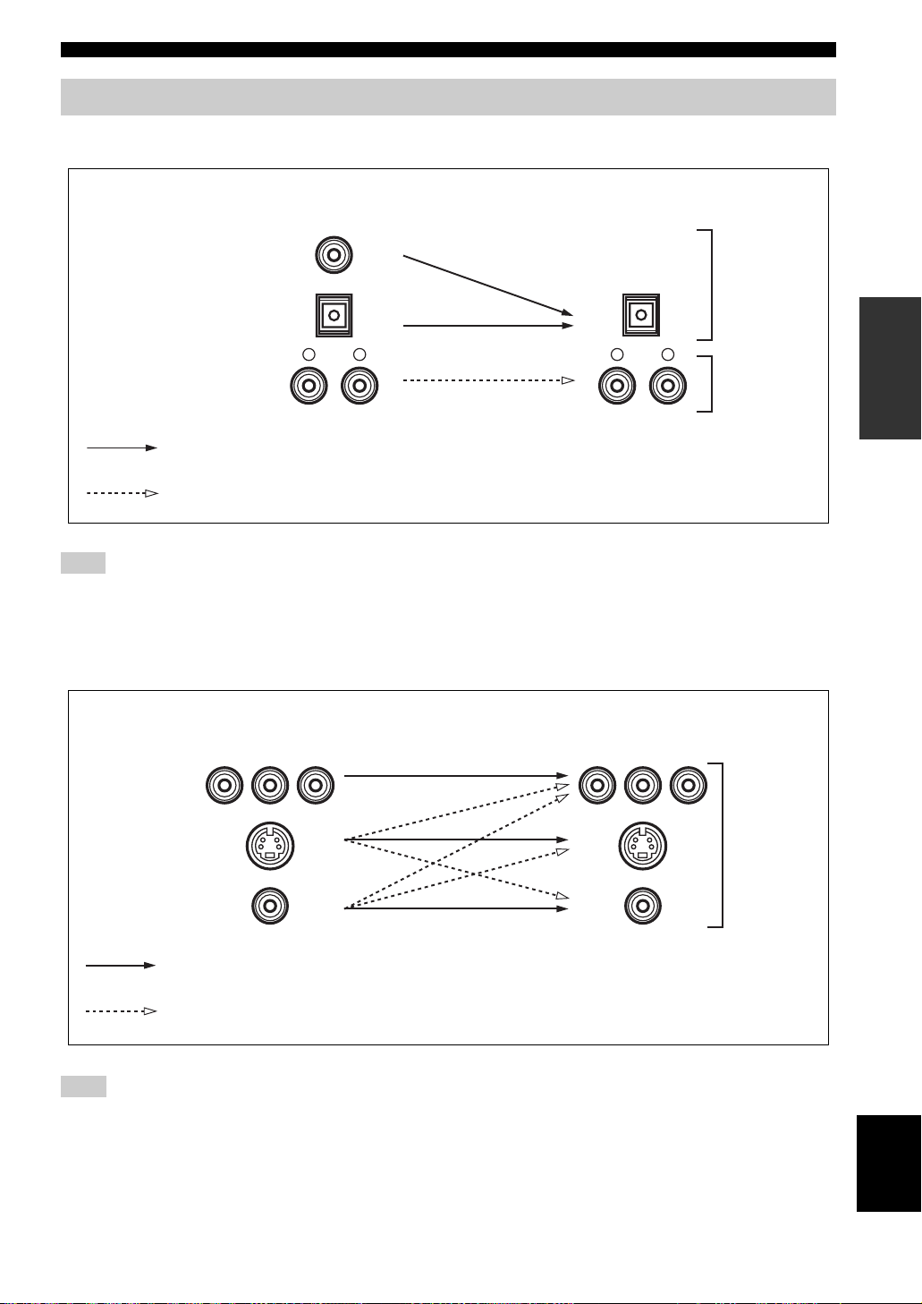
Audio and video signal flow
■ Audio signal flow for AUDIO OUT (REC)
CONNECTIONS
Input
Output
AUDIO OUT (REC)
DIGITAL AUDIO
COAXIAL
Digital audio
DIGITAL AUDIO
OPTICAL
RLRL
AUDIO
Digital output
Analog output
Analog audio
Note
This unit handles digital and analog signals independently. Thus, audio signals input at the analog jacks are output only at the analog
AUDIO OUT (REC) jacks. Likewise, audio signals input at the DIGITAL INPUT (OPTICAL or COAXIAL) jacks are output only at the
DIGITAL OUTPUT jack.
■ Video signal flow for MONITOR OUT
PREPARATION
Input
Y PBP
R
Output
(MONITOR OUT)
Y PBP
R
COMPONENT
VIDEO
S VIDEO
Analog video
VIDEO
Through
Video conversion when “VIDEO CONV.” is set to “ON” (see page 78)
Note
If video signals are input at the COMPONENT VIDEO, S VIDEO and VIDEO jacks simultaneously when “VIDEO CONV.” is set to
“ON”, the priority order of the input signals is as follows:
COMPONENT VIDEO > S VIDEO > VIDEO
English
17 En
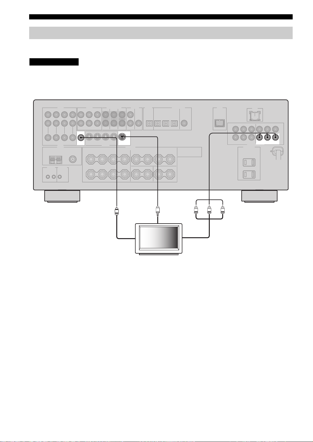
CONNECTIONS
Connecting a TV
Connect your TV to the VIDEO MONITOR OUT jack, the S VIDEO MONITOR OUT jack or the COMPONENT
VIDEO MONITOR OUT jacks of this unit.
CAUTION
Do not connect this unit or other components to the AC power supply until all connections between
components are complete.
PRPBY
MONITOR
VIDEO S VIDEO
OUT
MONITOR
OUT
V
Video in
S
S-video in
TV
Y
Component video in
MONITOR OUT
COMPONENT VIDEO
PRPB
18 En
CONNECTIONS
Connecting a DVD player, a DVD recorder, a VCR or an STB
Connect your DVD player, DVD recorder, VCR or STB (set-top box) using the same type of video connections as those
made for your TV (see page 18). The cable TV receiver and the satellite receiver are examples of the STB.
CAUTION
Do not connect this unit or other components to the AC power supply until all connections between
components are complete.
Notes
• When “VIDEO CONV.” is set to “OFF” (see page 78), be sure to make the same type of video connections as those made for your TV
(see page 18). For example, if you connected your TV to the VIDEO MONITOR OUT jack of this unit, connect your other
components to the VIDEO jacks.
• When “VIDEO CONV.” is set to “ON” (see page 78), the converted video signals are output only at the MONITOR OUT jacks. When
recording a source, you must make the same type of video connections between each component.
• To make a digital connection to a component other than the default component assigned to each DIGITAL INPUT or DIGITAL
OUTPUT jack, select the corresponding setting for “OPTICAL OUT”, “OPTICAL IN”, or “COAXIAL IN” in “I/O ASSIGNMENT”
(see page 74).
• If you connect your DVD player to both the DIGITAL INPUT (OPTICAL) and the DIGITAL INPUT (COAXIAL) jacks, priority is
given to the signals input at the DIGITAL INPUT (COAXIAL) jack.
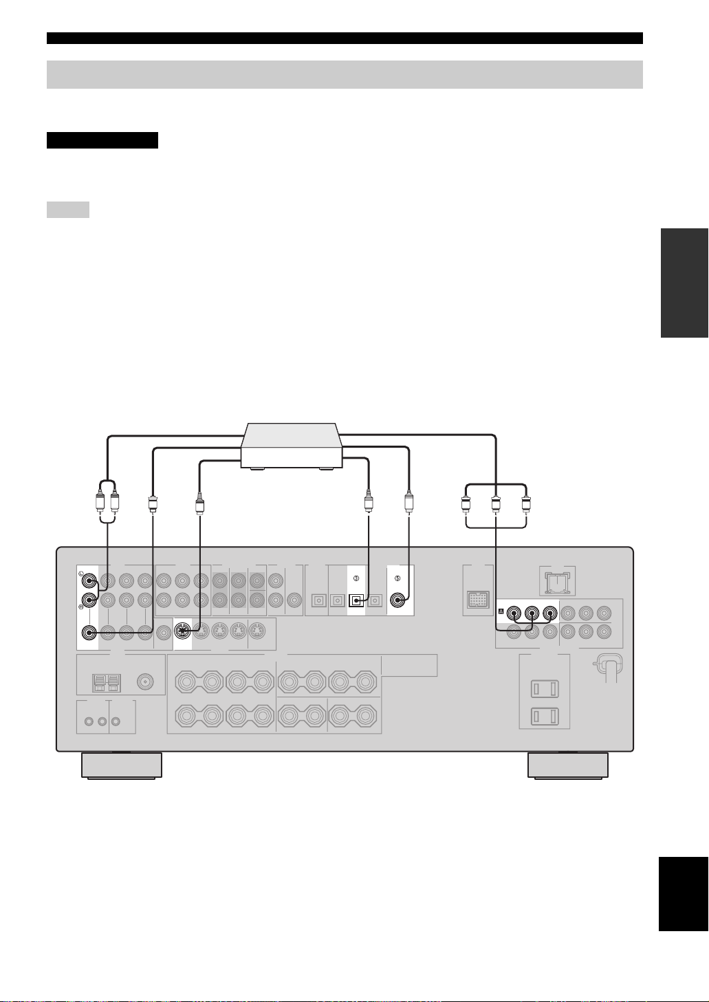
■ Connecting a DVD player
PREPARATION
Audio out
DVD player
LR
V
AUDIO DIGITAL INPUT
DVD DVD
VIDEO S VIDEO
Video out
S
S-video out
O
Optical audio out
DVD DVD
OPTICAL
Component video out
C
Coaxial audio out
COAXIAL
P
RPBY
RPBY
DVD
P
COMPONENT VIDEO
19 En
English
CONNECTIONS
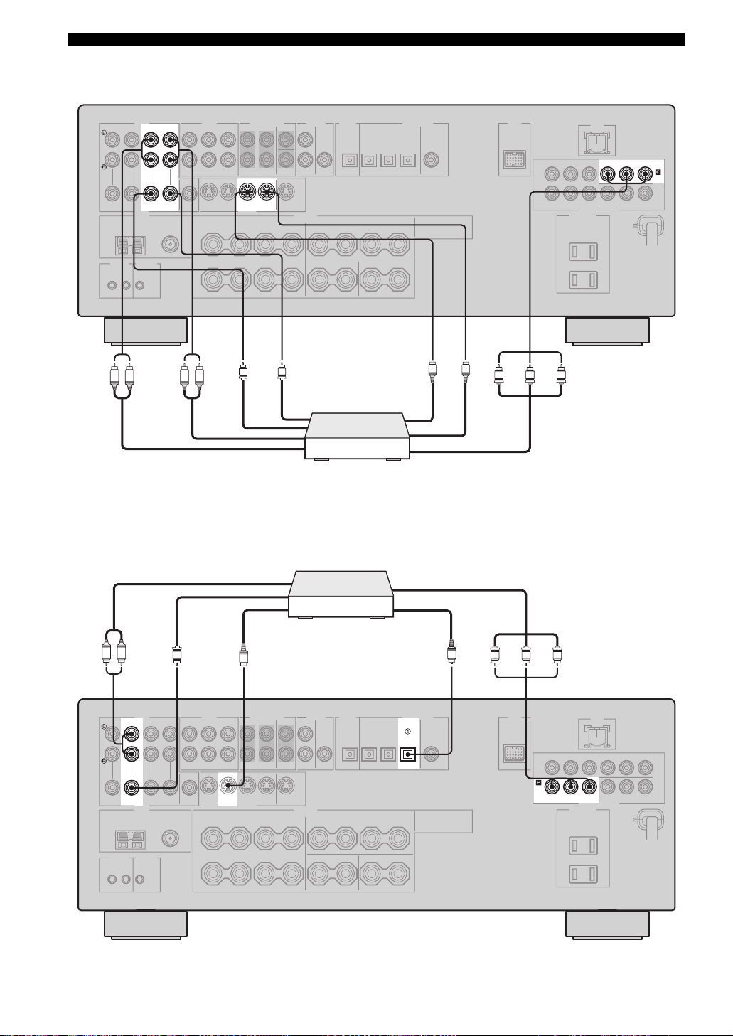
■ Connecting a DVD recorder or a VCR
AUDIO
PRPBY
DVR
IN OUT
DVR
VIDEO S VIDEO
LR LR
Audio out
Audio in
■ Connecting an STB
Video out
IN OUT
V
DVR
V
Video in
Cable TV receiver or
satellite receiver
DVD recorder or
VCR
COMPONENT VIDEO
S
S
S-video in
S-video out
PRPBY
Component video out
Component video out
20 En
LR
DTV/CBL DTV/CBL
V
Audio out
AUDIO DIGITAL INPUT
VIDEO S VIDEO
Video out
S
S-video out
OPTICAL
DTV/CBL
O
RPBY
P
Optical audio out
P
RPBY
DTV/
CBL
COMPONENT VIDEO
CONNECTIONS
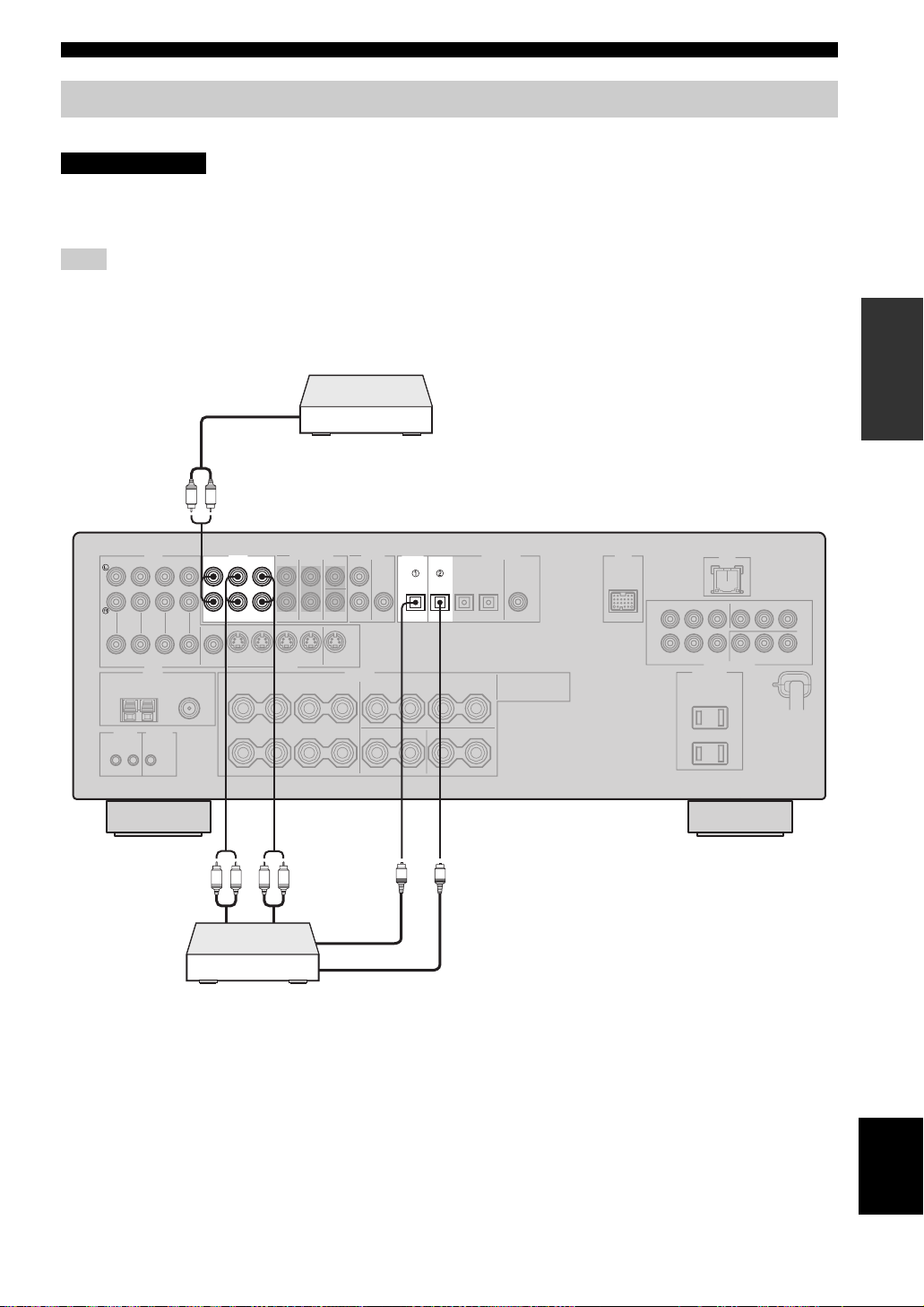
Connecting a CD player, an MD player or a tape deck
Connect your CD player, MD player or tape deck via analog and/or digital connections.
CAUTION
Do not connect this unit or other components to the AC power supply until all connections between
components are complete.
Note
To make a digital connection to a component other than the default component assigned to each DIGITAL INPUT or DIGITAL
OUTPUT jack, select the corresponding setting for “OPTICAL OUT”, “OPTICAL IN”, or “COAXIAL IN” in “I/O ASSIGNMENT”
(see page 74).
CD player
Audio out
LR
PREPARATION
Audio out
AUDIO DIGITAL INPUT
MD/
IN
OUT
CD-R
CD
(REC)
(PLAY)
LR LR
Audio in
DIGITAL
OUTPUT
MD/CD-RMD/CD-R
OPTICAL OPTICAL
O
O
Optical audio in
MD recorder or
tape deck
Optical audio out
21 En
English
CONNECTIONS
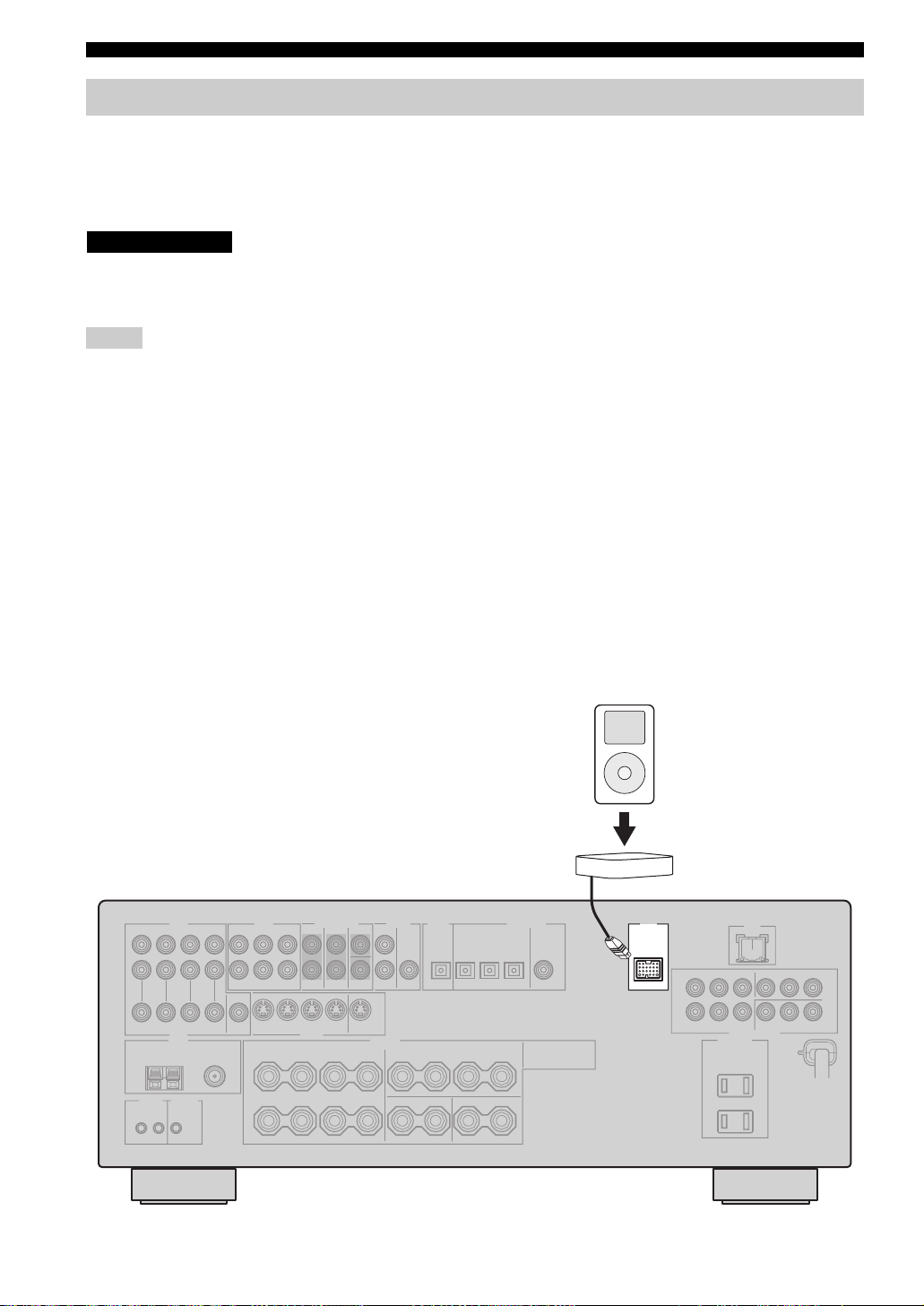
Connecting a YAMAHA iPod universal dock
This unit is equipped with the DOCK terminal on the rear panel that allows you to connect a YAMAHA iPod universal
dock (such as YDS-10 sold separately) where you can station your iPod and control playback of your iPod using the
supplied remote control. Connect a YAMAHA iPod universal dock (such as YDS-10 sold separately) to the DOCK
terminal on the rear panel of this unit using its dedicated cable. Once the connection is complete, station your iPod in the
YAMAHA iPod universal dock.
CAUTION
Do not connect this unit or other components to the AC power supply until all connections between
components are complete.
Notes
• Only iPod (Click and Wheel), iPod nano, and iPod mini are supported.
• You need a YAMAHA iPod universal dock (such as YDS-10 sold separately) and its dedicated cable compatible with the DOCK
terminal of this unit.
• Do not connect any iPod accessories (such as headphones, a wired remote control, or an FM transmitter) to your iPod when it is
stationed in a YAMAHA iPod universal dock (such as YDS-10 sold separately).
• Once your iPod is stationed in a YAMAHA iPod universal dock (such as YDS-10 sold separately) connected to the DOCK terminal of
this unit, this unit begins the signal transmission with your iPod.
• Unless your iPod is firmly stationed in a YAMAHA iPod universal dock (such as YDS-10 sold separately) connected to the DOCK
terminal of this unit, audio and/or video signals may not be output properly.
• Once the connection between your iPod and this unit is complete, “iPod connected” appears in the front panel display and the DOCK
indicator lights up in the front panel display. If the connection between your iPod and this unit fails, a status message appears in the
front panel display. For a complete list of connection status messages, see the iPod section in “TROUBLESHOOTING” on page 104.
• Only analog audio and video signals of your iPod are input at the DOCK terminal, and the analog audio signals can be output at the
analog AUDIO OUT (REC) jacks for recording.
• Your iPod battery is automatically charged when your iPod is stationed in a YAMAHA iPod universal dock (such as YDS-10 sold
separately) connected to the DOCK terminal of this unit as long as this unit is turned on.
• Depending on the type of iPod, you may need to insert one of the iPod adapters supplied with a YAMAHA iPod universal dock (such
as YDS-10 sold separately) into the dock slot before you station your iPod.
22 En
iPod
YAMAHA iPod universal dock
(such as YDS-10 sold separately)
DOCK
CONNECTIONS
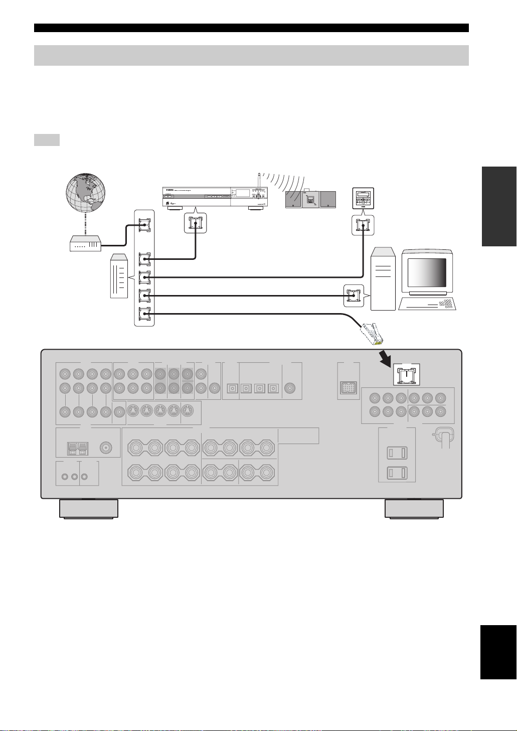
Connecting the network
To connect this unit to your network, plug one end of a network cable (CAT-5 or higher straight cable) into the LAN port
of this unit, and plug the other end into one of the LAN ports on your router that supports the DHCP (Dynamic Host
Configuration Protocol) server function. The following diagram shows a connection example where this unit is connected
to one of the LAN ports on a 4-port router. To enjoy music files saved on your PC and YAMAHA MCX-2000 or access
the Internet radio, each device must be connected properly in the network.
Note
If the DHCP server function on your router is disabled, you need to configure the network settings manually (see page 76).
YAMAHA MCX-2000
PREPARATION
Modem
Internet
Router
WAN
YAMAHA MCX-C15
YAMAHA MCX-A10
(with optional
speakers)
LAN
Network cable
PC
LAN
23 En
English
CONNECTIONS
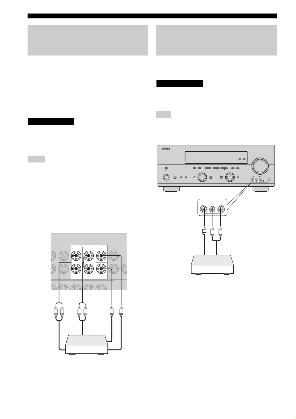
Connecting a multi-format player, an external decoder or a sound processor
This unit is equipped with 6 additional input jacks
(FRONT L/R, CENTER, SURROUND L/R and
SUBWOOFER) for discrete multi-channel input from a
multi-format player, external decoder or sound processor.
Connect the output jacks on your multi-format player,
external decoder or sound processor to the MULTI CH
INPUT jacks. Be sure to match the left and right output
jacks to the left and right input jacks for the front and
surround channels.
CAUTION
Do not connect this unit or other components to
the AC power supply until all connections
between components are complete.
Notes
• When you select the component connected to the MULTI CH
INPUT jacks as the input source (see page 38), this unit
automatically turns off the digital sound field processor, and
you cannot select sound field programs.
• This unit does not redirect signals input at the MULTI CH
INPUT jacks to accommodate for missing speakers. We
recommend that you connect at least a 5.1-channel speaker
system before using this feature.
• When headphones are used, only the signals input at the
FRONT L/R jacks are output at the PHONES jack.
Connecting a game console, a video camera or a portable audio player
Use the VIDEO AUX jacks on the front panel to connect a
game console, a video camera or a portable audio player to
this unit.
CAUTION
Be sure to turn off the volume of this unit and
other components before making connections.
Note
The audio signals input at the DOCK terminal takes priority over
the ones input at the VIDEO AUX jacks.
ZONE 2
ON/OFF
MASTER
ON OFF
MAIN ZONE
SPEAKERSPHONES
ON/OFF
SILENT CINEMA
FM/AM
PRESET/TUNING
A/B/C/D/E
NEXTEDIT
PROGRAM
BA
EFFECT
VIDEO AUX
VIDEO L AUDIO R
l PRESET/TUNING h
LEVEL
INPUT MODETONE CONTROLSTRAIGHT
MEMORY
TUNING MODE
MAN'L/AUTO FM
AUTO/MAN'L
INPUT
MULTI CH
INPUT
VOLUME
ZONE
CONTROL
USBVIDEO AUX
VIDEO L AUDIO R
L R L R
Front out
Multi-format player,
external decoder or
sound processor
MULTI CH INPUT
FRONT
Surround out
SURROUND
CENTER
SUB
WOOFER
V
LR
Video out
Audio out
Game console,
video camera or
portable audio player
Subwoofer out
Center out
24 En
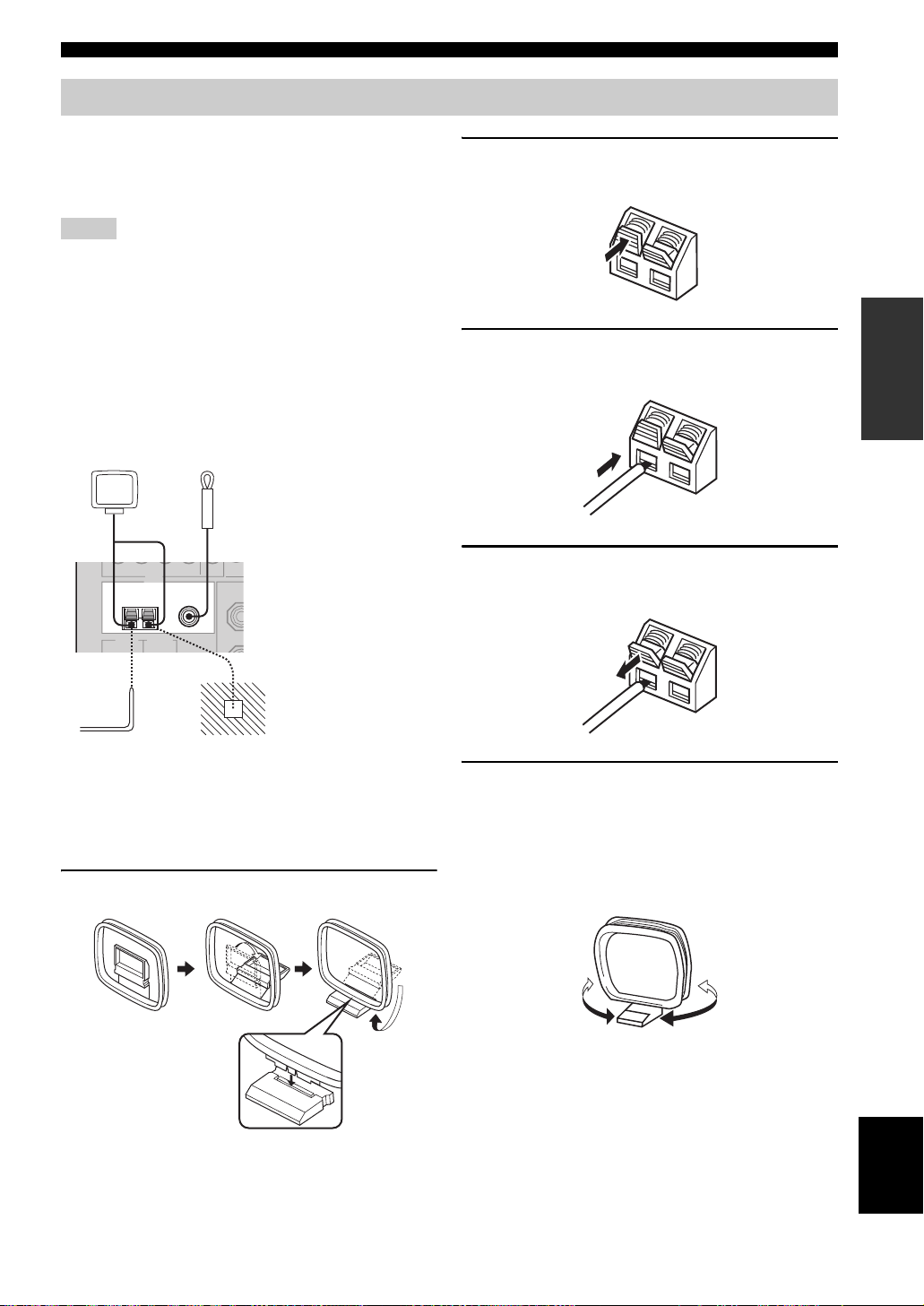
Connecting the FM and AM antennas
Both FM and AM indoor antennas are supplied with this
unit. In general, these antennas should provide sufficient
signal strength. Connect each antenna correctly to the
designated terminals.
Notes
• Be sure to set the tuner frequency step (General model only)
according to the frequency spacing in your area (see page 83).
• The AM loop antenna should be placed away from this unit.
• The AM loop antenna should always be connected, even if an
outdoor AM antenna is connected to this unit.
• A properly installed outdoor antenna provides clearer reception
than an indoor one. If you experience poor reception quality,
install an outdoor antenna. Consult the nearest authorized
YAMAHA dealer or service center about outdoor antennas.
AM loop antenna
(supplied)
Indoor FM antenna
(supplied)
CONNECTIONS
2 Press and hold the tab of the AM ANT
terminal.
PREPARATION
3 Insert one of the AM loop antenna lead wires
into the AM ANT terminal.
TUNER
FM ANT
AM
ANT
Outdoor AM antenna
Use a 5 to 10 m of vinyl-covered wire
extended from a window.
75Ω
GND
UNBAL.
Ground (GND terminal)
For maximum safety and
minimum interference,
connect the antenna GND
terminal to a good earth
ground. A good earth ground
is a metal stake driven into
moist earth.
■ Connecting the AM loop antenna
1 Set up the AM loop antenna.
4 Release the tab of the AM ANT terminal back
into place.
5 Repeat steps 2 through 4 to connect the
other lead wire to the GND terminal.
y
Once you have properly connected the AM loop antenna to this
unit, orient the AM loop antenna for the best reception when you
tune into AM stations.
25 En
English
CONNECTIONS
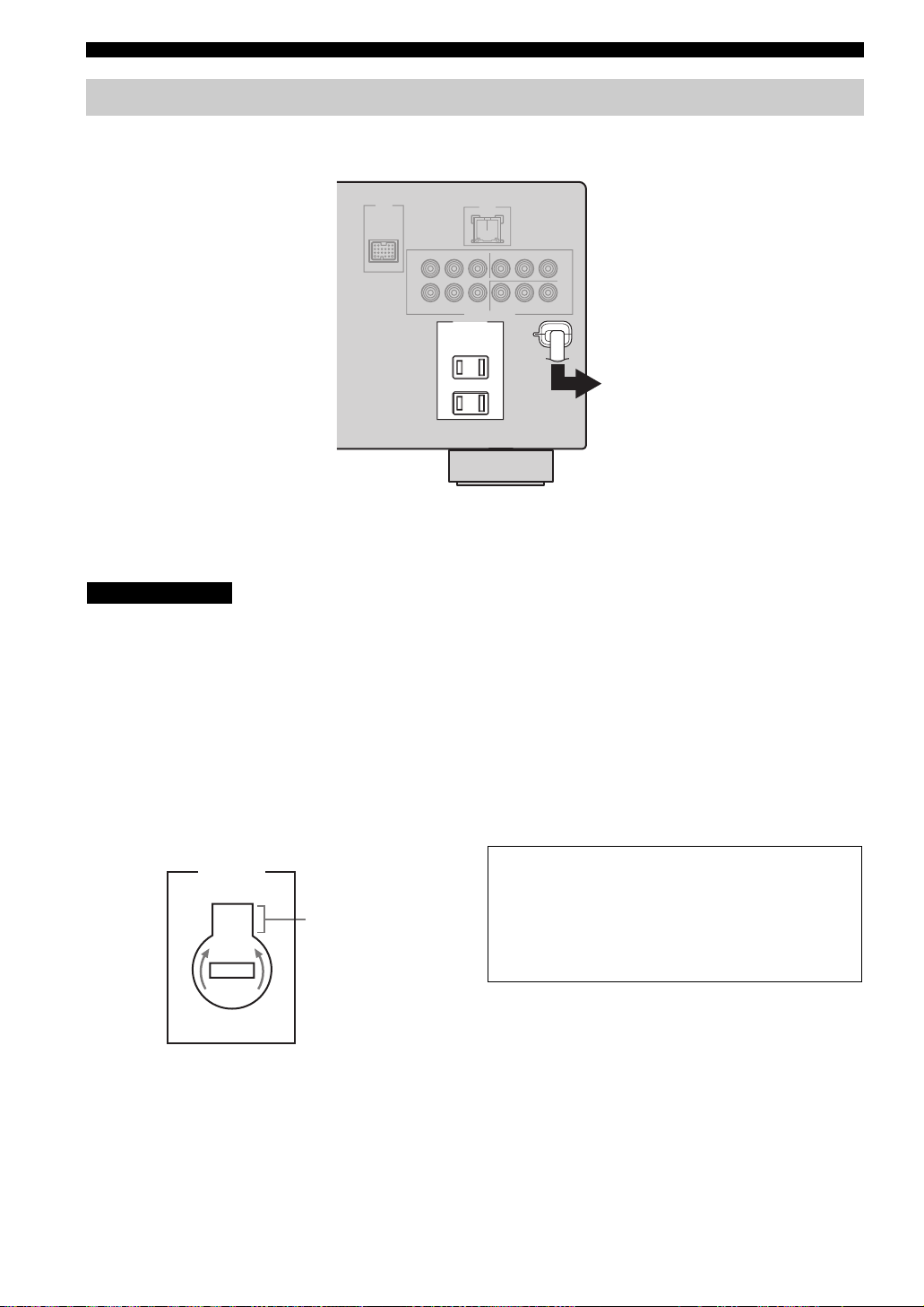
Connecting the power cable
Once all connections are complete, plug the power cable into the AC wall outlet.
(U.S.A. model)
AC OUTLETS
To the AC wall outlet
■ VOLTAGE SELECTOR
(General model only)
CAUTION
The VOLTAGE SELECTOR on the rear panel of
this unit must be set for your local voltage
BEFORE plugging the power cable into the AC
wall outlet. Improper setting of the VOLTAGE
SELECTOR may cause damage to this unit and
create a potential fire hazard.
Rotate the VOLTAGE SELECTOR clockwise or
counterclockwise to the correct position using a
straight slot screwdriver.
Voltages are 110/120/220/230–240 V AC, 50/60 Hz.
VOLTAGE
SELECTOR
230240V
Voltage indication
■ AC OUTLET(S) (SWITCHED)
Australia model...................................................... 1 outlet
Korea model............................................................... None
Other models......................................................... 2 outlets
Use these outlet(s) to supply power to any connected
components. Connect the power cable of your other
components to these outlet(s). Power to these outlet(s) is
supplied when the main zone or Zone 2 is turned on.
However, power to these outlet(s) is cut off when both the
main zone and Zone 2 are turned off or when MASTER
ON/OFF on the front panel is pressed and released
outward to the OFF position. For information on the
maximum power or the total power consumption of the
components that can be connected to these outlet(s), see
“SPECIFICATIONS” on page 110.
Memory back-up
The memory back-up circuit prevents the stored data
from being lost even if this unit is in the standby mode.
However, the stored data will be lost in case the power
cable is disconnected from the AC wall outlet or if the
power supply is cut off for more than one week.
26 En
Setting the speaker impedance
CONNECTIONS
CAUTION
If you are to use 6 ohm speakers, set “SP IMP.” to
“6ΩMIN” as follows BEFORE using this unit. 4
ohm speakers can be also used as the front
speakers.
2,5
2,5
MASTER
MASTER
ON OFF
ON OFF
MAIN ZONE
MAIN ZONE
SPEAKERSPHONES
SPEAKERSPHONES
ON/OFF
ON/OFF
SILENT CINEMA
SILENT CINEMA
FM/AM
FM/AM
PRESET/TUNING
A/B/C/D/E
PRESET/TUNING
BA
BA
EFFECT
EFFECT
l PRESET/TUNING h
A/B/C/D/E
l PRESET/TUNING h
NEXTEDIT
LEVEL
NEXTEDIT
PROGRAM
PROGRAM
32,4
32,4
LEVEL
INPUT MODETONE CONTROLSTRAIGHT
INPUT MODETONE CONTROLSTRAIGHT
MEMORY
TUNING MODE
MEMORY
TUNING MODE
MAN'L/AUTO FM
AUTO/MAN'L
MAN'L/AUTO FM
AUTO/MAN'L
INPUT
INPUT
MULTI CH
MULTI CH
INPUT
INPUT
(U.S.A. model)
ZONE 2
ZONE
ZONE 2
ZONE
ON/OFF
CONTROL
ON/OFF
CONTROL
VIDEO L AUDIO R
VIDEO L AUDIO R
VOLUME
VOLUME
USBVIDEO AUX
USBVIDEO AUX
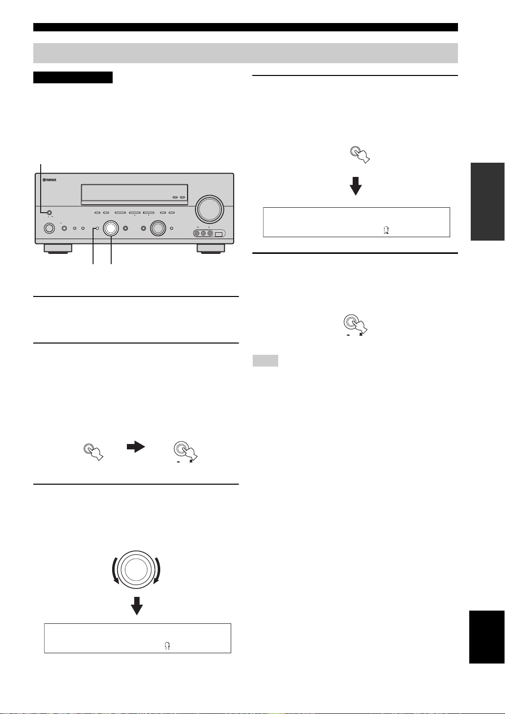
1 Make sure this unit is turned off.
See page 28 for details about turning on or off this
unit.
2 Press and hold STRAIGHT (EFFECT) on the
front panel and then press MASTER ON/OFF
inward to the ON position to turn on this unit.
This unit turns on, and the advanced setup menu
appears in the front panel display.
4 Press STRAIGHT (EFFECT) on the front
panel repeatedly to select “6ΩMIN”.
The following display appears in the front panel
display.
STRAIGHT
EFFECT
SP IMP.-6 MIN
5 Press MASTER ON/OFF on the front panel to
release it outward to the OFF position to save
the new setting and turn off this unit.
MASTER
ON OFF
Note
The setting you made is reflected next time you turn on this unit.
PREPARATION
While holding
down
STRAIGHT
EFFECT
MASTER
ON OFF
3 Rotate the PROGRAM selector on the front
panel to select “SP IMP.”.
The following display appears in the front panel
display.
PROGRAM
SP IMP.-8 MIN
English
27 En
CONNECTIONS
AMP
SOURCE
TV
VOLUME
TV VOL TV CH
TRANSMITCODE SET
STANDBY
POWER
POWERPOWER
CD
AVTV
MULTI CH IN
SLEEP
CD-R
DVD DT V
MD
DOCK USB
CBL
NET
TUNER
V-AUX DVR
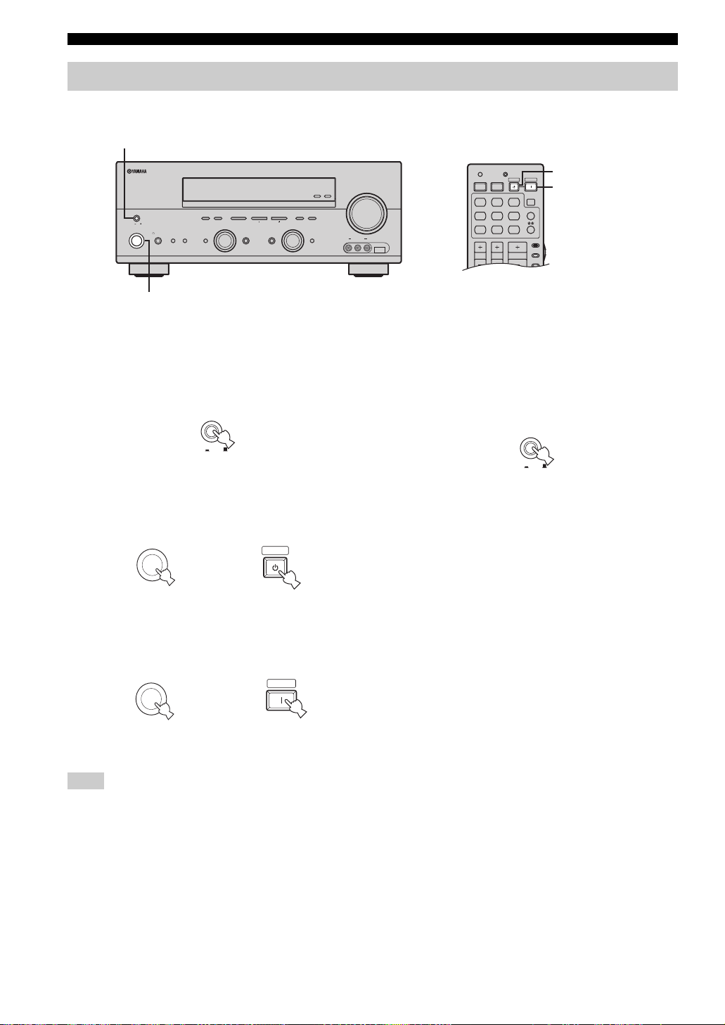
Turning on and off the power
When all connections are complete, turn on this unit.
MASTER ON/OFF
ZONE 2
ON/OFF
CONTROL
MASTER
ON OFF
MAIN ZONE
SPEAKERSPHONES
ON/OFF
BA
SILENT CINEMA
MAIN ZONE ON/OFF
PRESET/TUNING
FM/AM
A/B/C/D/E
NEXTEDIT
PROGRAM
EFFECT
PRESET/TUNING
l
MEMORY
TUNING MODE
h
LEVEL
MAN'L/AUTO FM
AUTO/MAN'L
INPUT
INPUT MODETONE CONTROLSTRAIGHT
MULTI CH
INPUT
STANDBY
VOLUME
ZONE
USBVIDEO AUX
VIDEO L AUDIO R
POWER
■ Turning on this unit
Press MASTER ON/OFF on the front panel inward
to the ON position to turn on this unit.
MASTER
ON OFF
Front panel
• Press MAIN ZONE ON/OFF on the front panel (or
STANDBY on the remote control) to set the main zone
to the standby mode.
MAIN ZONE
ON/OFF
or
Front panel Remote control
• Press MAIN ZONE ON/OFF on the front panel (or
POWER on the remote control) to turn on the main
zone.
MAIN ZONE
ON/OFF
Front panel
or
STANDBY
POWER
Remote control
■ Turning off this unit
Press MASTER ON/OFF on the front panel to
release it outward to the OFF position to turn off
this unit.
MASTER
ON OFF
Front panel
Note
MAIN ZONE ON/OFF on the front panel as well as POWER and
STANDBY on the remote control are operational only when
MASTER ON/OFF is pressed inward to the ON position.
y
For details about turning on or off Zone 2, see page 90
28 En
 Loading...