

Page 1

AV Receiver
Owner’s Manual
English
Read the supplied booklet “Safety Brochure” before using the unit.
Page 2

CONTENTS
Accessories . . . . . . . . . . . . . . . . . . . . . . . . . . . . . . . . . . . . . . . . . . . . . . . . . . . . . . 4
FEATURES 5
What you can do with the unit . . . . . . . . . . . . . . . . . . . . . . . . . . . . . . . . . . . . 5
Part names and functions . . . . . . . . . . . . . . . . . . . . . . . . . . . . . . . . . . . . . . . . 7
Front panel . . . . . . . . . . . . . . . . . . . . . . . . . . . . . . . . . . . . . . . . . . . . . . . . . . . . . . . . . . . . . . . . . . . . . . . . . . . . . . . . . . . . . . . . 7
Front display (indicators) . . . . . . . . . . . . . . . . . . . . . . . . . . . . . . . . . . . . . . . . . . . . . . . . . . . . . . . . . . . . . . . . . . . . . . . . . . . 8
Rear panel . . . . . . . . . . . . . . . . . . . . . . . . . . . . . . . . . . . . . . . . . . . . . . . . . . . . . . . . . . . . . . . . . . . . . . . . . . . . . . . . . . . . . . . . . 9
Remote control . . . . . . . . . . . . . . . . . . . . . . . . . . . . . . . . . . . . . . . . . . . . . . . . . . . . . . . . . . . . . . . . . . . . . . . . . . . . . . . . . . . 10
PREPARATIONS 11
General setup procedure . . . . . . . . . . . . . . . . . . . . . . . . . . . . . . . . . . . . . . . . 11
1 Placing speakers . . . . . . . . . . . . . . . . . . . . . . . . . . . . . . . . . . . . . . . . . . . . . . 12
2 Connecting speakers . . . . . . . . . . . . . . . . . . . . . . . . . . . . . . . . . . . . . . . . . . 15
5.1-channel system . . . . . . . . . . . . . . . . . . . . . . . . . . . . . . . . . . . . . . . . . . . . . . . . . . . . . . . . . . . . . . . . . . . . . . . . . . . . . . . 15
Input/output jacks and cables . . . . . . . . . . . . . . . . . . . . . . . . . . . . . . . . . . . 17
3 Connecting a TV . . . . . . . . . . . . . . . . . . . . . . . . . . . . . . . . . . . . . . . . . . . . . . . 18
4 Connecting playback devices . . . . . . . . . . . . . . . . . . . . . . . . . . . . . . . . . . 20
Connecting video devices (such as BD/DVD players) . . . . . . . . . . . . . . . . . . . . . . . . . . . . . . . . . . . . . . . . . . . . . . . 20
Connecting audio devices (such as CD players) . . . . . . . . . . . . . . . . . . . . . . . . . . . . . . . . . . . . . . . . . . . . . . . . . . . . . 22
Connecting to the jack on the front panel . . . . . . . . . . . . . . . . . . . . . . . . . . . . . . . . . . . . . . . . . . . . . . . . . . . . . . . . . . 23
5 Connecting the FM/AM antennas . . . . . . . . . . . . . . . . . . . . . . . . . . . . . . . 23
6 Preparing for connecting to a network . . . . . . . . . . . . . . . . . . . . . . . . . . 24
7 Connecting the power cable . . . . . . . . . . . . . . . . . . . . . . . . . . . . . . . . . . . 25
8 Selecting an on-screen menu language . . . . . . . . . . . . . . . . . . . . . . . . . 26
9 Optimizing the speaker settings automatically (YPAO) . . . . . . . . . . 27
Error messages . . . . . . . . . . . . . . . . . . . . . . . . . . . . . . . . . . . . . . . . . . . . . . . . . . . . . . . . . . . . . . . . . . . . . . . . . . . . . . . . . . . . 29
Warning messages . . . . . . . . . . . . . . . . . . . . . . . . . . . . . . . . . . . . . . . . . . . . . . . . . . . . . . . . . . . . . . . . . . . . . . . . . . . . . . . .30
10 Connecting to a network wirelessly . . . . . . . . . . . . . . . . . . . . . . . . . . . 31
Selecting the connection method . . . . . . . . . . . . . . . . . . . . . . . . . . . . . . . . . . . . . . . . . . . . . . . . . . . . . . . . . . . . . . . . . . 31
Connecting the unit to a wireless network . . . . . . . . . . . . . . . . . . . . . . . . . . . . . . . . . . . . . . . . . . . . . . . . . . . . . . . . .32
Connecting a mobile device to the unit directly (Wireless Direct) . . . . . . . . . . . . . . . . . . . . . . . . . . . . . . . . . . . . 39
PLAYBACK 41
Basic playback procedure . . . . . . . . . . . . . . . . . . . . . . . . . . . . . . . . . . . . . . . 41
Selecting the input source and favorite settings with one touch
(SCENE) . . . . . . . . . . . . . . . . . . . . . . . . . . . . . . . . . . . . . . . . . . . . . . . . . . . . . . . . 42
Selecting a registered scene . . . . . . . . . . . . . . . . . . . . . . . . . . . . . . . . . . . . . . . . . . . . . . . . . . . . . . . . . . . . . . . . . . . . . . .42
Configuring scene assignments . . . . . . . . . . . . . . . . . . . . . . . . . . . . . . . . . . . . . . . . . . . . . . . . . . . . . . . . . . . . . . . . . . . .42
Selecting the sound mode . . . . . . . . . . . . . . . . . . . . . . . . . . . . . . . . . . . . . . . 43
Enjoying stereoscopic sound fields (CINEMA DSP 3D) . . . . . . . . . . . . . . . . . . . . . . . . . . . . . . . . . . . . . . . . . . . . . . .44
Enjoying unprocessed playback . . . . . . . . . . . . . . . . . . . . . . . . . . . . . . . . . . . . . . . . . . . . . . . . . . . . . . . . . . . . . . . . . . . 46
Enjoying pure high fidelity sound (direct playback) . . . . . . . . . . . . . . . . . . . . . . . . . . . . . . . . . . . . . . . . . . . . . . . . .47
Enhancing the bass (Extra Bass) . . . . . . . . . . . . . . . . . . . . . . . . . . . . . . . . . . . . . . . . . . . . . . . . . . . . . . . . . . . . . . . . . . . .47
Enjoying compressed music with enhanced sound (Compressed Music Enhancer) . . . . . . . . . . . . . . . . . . .47
Listening to FM/AM radio . . . . . . . . . . . . . . . . . . . . . . . . . . . . . . . . . . . . . . . 48
Setting the frequency steps . . . . . . . . . . . . . . . . . . . . . . . . . . . . . . . . . . . . . . . . . . . . . . . . . . . . . . . . . . . . . . . . . . . . . . . .48
Selecting a frequency for reception . . . . . . . . . . . . . . . . . . . . . . . . . . . . . . . . . . . . . . . . . . . . . . . . . . . . . . . . . . . . . . . .48
Registering favorite radio stations (presets) . . . . . . . . . . . . . . . . . . . . . . . . . . . . . . . . . . . . . . . . . . . . . . . . . . . . . . . . 49
Radio Data System tuning . . . . . . . . . . . . . . . . . . . . . . . . . . . . . . . . . . . . . . . . . . . . . . . . . . . . . . . . . . . . . . . . . . . . . . . . .51
Playing back music via BLUETOOTH . . . . . . . . . . . . . . . . . . . . . . . . . . . . . . 52
Playback BLUETOOTH device music on the unit . . . . . . . . . . . . . . . . . . . . . . . . . . . . . . . . . . . . . . . . . . . . . . . . . . . . 52
Playing back iPod music . . . . . . . . . . . . . . . . . . . . . . . . . . . . . . . . . . . . . . . . . 53
Connecting an iPod . . . . . . . . . . . . . . . . . . . . . . . . . . . . . . . . . . . . . . . . . . . . . . . . . . . . . . . . . . . . . . . . . . . . . . . . . . . . . . .53
Playback of iPod content . . . . . . . . . . . . . . . . . . . . . . . . . . . . . . . . . . . . . . . . . . . . . . . . . . . . . . . . . . . . . . . . . . . . . . . . . . 53
En 2
Page 3

Playing back music with AirPlay . . . . . . . . . . . . . . . . . . . . . . . . . . . . . . . . . 56
Playback of iTunes/iPod music contents . . . . . . . . . . . . . . . . . . . . . . . . . . . . . . . . . . . . . . . . . . . . . . . . . . . . . . . . . . . 56
Playing back music stored on a USB storage device . . . . . . . . . . . . . . . 58
Connecting a USB storage device . . . . . . . . . . . . . . . . . . . . . . . . . . . . . . . . . . . . . . . . . . . . . . . . . . . . . . . . . . . . . . . . . . 58
Playback of USB storage device contents . . . . . . . . . . . . . . . . . . . . . . . . . . . . . . . . . . . . . . . . . . . . . . . . . . . . . . . . . . 58
Playing back music stored on media servers (PCs/NAS) . . . . . . . . . . . . 61
Media sharing setup . . . . . . . . . . . . . . . . . . . . . . . . . . . . . . . . . . . . . . . . . . . . . . . . . . . . . . . . . . . . . . . . . . . . . . . . . . . . . . 61
Playback of PC music contents . . . . . . . . . . . . . . . . . . . . . . . . . . . . . . . . . . . . . . . . . . . . . . . . . . . . . . . . . . . . . . . . . . . . 62
Listening to Internet radio . . . . . . . . . . . . . . . . . . . . . . . . . . . . . . . . . . . . . . . 64
Playback of Internet radio . . . . . . . . . . . . . . . . . . . . . . . . . . . . . . . . . . . . . . . . . . . . . . . . . . . . . . . . . . . . . . . . . . . . . . . . . 64
Registering favorite Internet radio stations (bookmarks) . . . . . . . . . . . . . . . . . . . . . . . . . . . . . . . . . . . . . . . . . . . . 66
Useful functions . . . . . . . . . . . . . . . . . . . . . . . . . . . . . . . . . . . . . . . . . . . . . . . . 67
Registering favorite items (shortcut) . . . . . . . . . . . . . . . . . . . . . . . . . . . . . . . . . . . . . . . . . . . . . . . . . . . . . . . . . . . . . . . 67
Switching information on the front display . . . . . . . . . . . . . . . . . . . . . . . . . . . . . . . . . . . . . . . . . . . . . . . . . . . . . . . . 68
Configuring playback settings for different playback sources
(Option menu) . . . . . . . . . . . . . . . . . . . . . . . . . . . . . . . . . . . . . . . . . . . . . . . . . . 69
Option menu items . . . . . . . . . . . . . . . . . . . . . . . . . . . . . . . . . . . . . . . . . . . . . . . . . . . . . . . . . . . . . . . . . . . . . . . . . . . . . . . 69
CONFIGURATIONS 72
Configuring various functions (Setup menu) . . . . . . . . . . . . . . . . . . . . . . 72
Setup menu items . . . . . . . . . . . . . . . . . . . . . . . . . . . . . . . . . . . . . . . . . . . . . . . . . . . . . . . . . . . . . . . . . . . . . . . . . . . . . . . . 73
Speaker . . . . . . . . . . . . . . . . . . . . . . . . . . . . . . . . . . . . . . . . . . . . . . . . . . . . . . . . . . . . . . . . . . . . . . . . . . . . . . . . . . . . . . . . . . . 75
HDMI . . . . . . . . . . . . . . . . . . . . . . . . . . . . . . . . . . . . . . . . . . . . . . . . . . . . . . . . . . . . . . . . . . . . . . . . . . . . . . . . . . . . . . . . . . . . . 78
Sound . . . . . . . . . . . . . . . . . . . . . . . . . . . . . . . . . . . . . . . . . . . . . . . . . . . . . . . . . . . . . . . . . . . . . . . . . . . . . . . . . . . . . . . . . . . . 80
ECO . . . . . . . . . . . . . . . . . . . . . . . . . . . . . . . . . . . . . . . . . . . . . . . . . . . . . . . . . . . . . . . . . . . . . . . . . . . . . . . . . . . . . . . . . . . . . . 82
Function . . . . . . . . . . . . . . . . . . . . . . . . . . . . . . . . . . . . . . . . . . . . . . . . . . . . . . . . . . . . . . . . . . . . . . . . . . . . . . . . . . . . . . . . . . 83
Network . . . . . . . . . . . . . . . . . . . . . . . . . . . . . . . . . . . . . . . . . . . . . . . . . . . . . . . . . . . . . . . . . . . . . . . . . . . . . . . . . . . . . . . . . . 85
Bluetooth . . . . . . . . . . . . . . . . . . . . . . . . . . . . . . . . . . . . . . . . . . . . . . . . . . . . . . . . . . . . . . . . . . . . . . . . . . . . . . . . . . . . . . . . . 87
Language . . . . . . . . . . . . . . . . . . . . . . . . . . . . . . . . . . . . . . . . . . . . . . . . . . . . . . . . . . . . . . . . . . . . . . . . . . . . . . . . . . . . . . . . . 88
Configuring the system settings (ADVANCED SETUP menu) . . . . . . . . 89
ADVANCED SETUP menu items . . . . . . . . . . . . . . . . . . . . . . . . . . . . . . . . . . . . . . . . . . . . . . . . . . . . . . . . . . . . . . . . . . . . 89
Changing the speaker impedance setting (SP IMP.) . . . . . . . . . . . . . . . . . . . . . . . . . . . . . . . . . . . . . . . . . . . . . . . . . 89
Selecting the remote control ID (REMOTE ID) . . . . . . . . . . . . . . . . . . . . . . . . . . . . . . . . . . . . . . . . . . . . . . . . . . . . . . . 90
Changing the FM/AM tuning frequency setting (TU) . . . . . . . . . . . . . . . . . . . . . . . . . . . . . . . . . . . . . . . . . . . . . . . . 90
Switching the video signal type (TV FORMAT) . . . . . . . . . . . . . . . . . . . . . . . . . . . . . . . . . . . . . . . . . . . . . . . . . . . . . . 90
Restoring the default settings (INIT) . . . . . . . . . . . . . . . . . . . . . . . . . . . . . . . . . . . . . . . . . . . . . . . . . . . . . . . . . . . . . . . .90
Updating the firmware (UPDATE) . . . . . . . . . . . . . . . . . . . . . . . . . . . . . . . . . . . . . . . . . . . . . . . . . . . . . . . . . . . . . . . . . . 91
Checking the firmware version (VERSION) . . . . . . . . . . . . . . . . . . . . . . . . . . . . . . . . . . . . . . . . . . . . . . . . . . . . . . . . . .91
Updating the unit’s firmware via the network . . . . . . . . . . . . . . . . . . . . 92
APPENDIX 93
Frequently asked questions . . . . . . . . . . . . . . . . . . . . . . . . . . . . . . . . . . . . . 93
Troubleshooting . . . . . . . . . . . . . . . . . . . . . . . . . . . . . . . . . . . . . . . . . . . . . . . . 95
Power, system and remote control . . . . . . . . . . . . . . . . . . . . . . . . . . . . . . . . . . . . . . . . . . . . . . . . . . . . . . . . . . . . . . . . .95
Audio . . . . . . . . . . . . . . . . . . . . . . . . . . . . . . . . . . . . . . . . . . . . . . . . . . . . . . . . . . . . . . . . . . . . . . . . . . . . . . . . . . . . . . . . . . . . .97
Video . . . . . . . . . . . . . . . . . . . . . . . . . . . . . . . . . . . . . . . . . . . . . . . . . . . . . . . . . . . . . . . . . . . . . . . . . . . . . . . . . . . . . . . . . . . . . 98
FM/AM radio . . . . . . . . . . . . . . . . . . . . . . . . . . . . . . . . . . . . . . . . . . . . . . . . . . . . . . . . . . . . . . . . . . . . . . . . . . . . . . . . . . . . . .99
USB and network . . . . . . . . . . . . . . . . . . . . . . . . . . . . . . . . . . . . . . . . . . . . . . . . . . . . . . . . . . . . . . . . . . . . . . . . . . . . . . . . .100
BLUETOOTH . . . . . . . . . . . . . . . . . . . . . . . . . . . . . . . . . . . . . . . . . . . . . . . . . . . . . . . . . . . . . . . . . . . . . . . . . . . . . . . . . . . . .101
Error indications on the front display . . . . . . . . . . . . . . . . . . . . . . . . . . . 102
Glossary . . . . . . . . . . . . . . . . . . . . . . . . . . . . . . . . . . . . . . . . . . . . . . . . . . . . . . 103
Audio information . . . . . . . . . . . . . . . . . . . . . . . . . . . . . . . . . . . . . . . . . . . . . . . . . . . . . . . . . . . . . . . . . . . . . . . . . . . . . . . .103
HDMI and video information . . . . . . . . . . . . . . . . . . . . . . . . . . . . . . . . . . . . . . . . . . . . . . . . . . . . . . . . . . . . . . . . . . . . . .104
Network information . . . . . . . . . . . . . . . . . . . . . . . . . . . . . . . . . . . . . . . . . . . . . . . . . . . . . . . . . . . . . . . . . . . . . . . . . . . . .104
Yamaha technologies . . . . . . . . . . . . . . . . . . . . . . . . . . . . . . . . . . . . . . . . . . . . . . . . . . . . . . . . . . . . . . . . . . . . . . . . . . . .105
Supported devices and file formats . . . . . . . . . . . . . . . . . . . . . . . . . . . . . 105
Video signal flow . . . . . . . . . . . . . . . . . . . . . . . . . . . . . . . . . . . . . . . . . . . . . . 106
Information on HDMI . . . . . . . . . . . . . . . . . . . . . . . . . . . . . . . . . . . . . . . . . . 107
HDMI Control . . . . . . . . . . . . . . . . . . . . . . . . . . . . . . . . . . . . . . . . . . . . . . . . . . . . . . . . . . . . . . . . . . . . . . . . . . . . . . . . . . . .107
Audio Return Channel (ARC) . . . . . . . . . . . . . . . . . . . . . . . . . . . . . . . . . . . . . . . . . . . . . . . . . . . . . . . . . . . . . . . . . . . . . .108
HDMI signal compatibility . . . . . . . . . . . . . . . . . . . . . . . . . . . . . . . . . . . . . . . . . . . . . . . . . . . . . . . . . . . . . . . . . . . . . . . .109
Trademarks . . . . . . . . . . . . . . . . . . . . . . . . . . . . . . . . . . . . . . . . . . . . . . . . . . . 110
Specifications . . . . . . . . . . . . . . . . . . . . . . . . . . . . . . . . . . . . . . . . . . . . . . . . . 111
Index . . . . . . . . . . . . . . . . . . . . . . . . . . . . . . . . . . . . . . . . . . . . . . . . . . . . . . . . . 114
En 3
Page 4
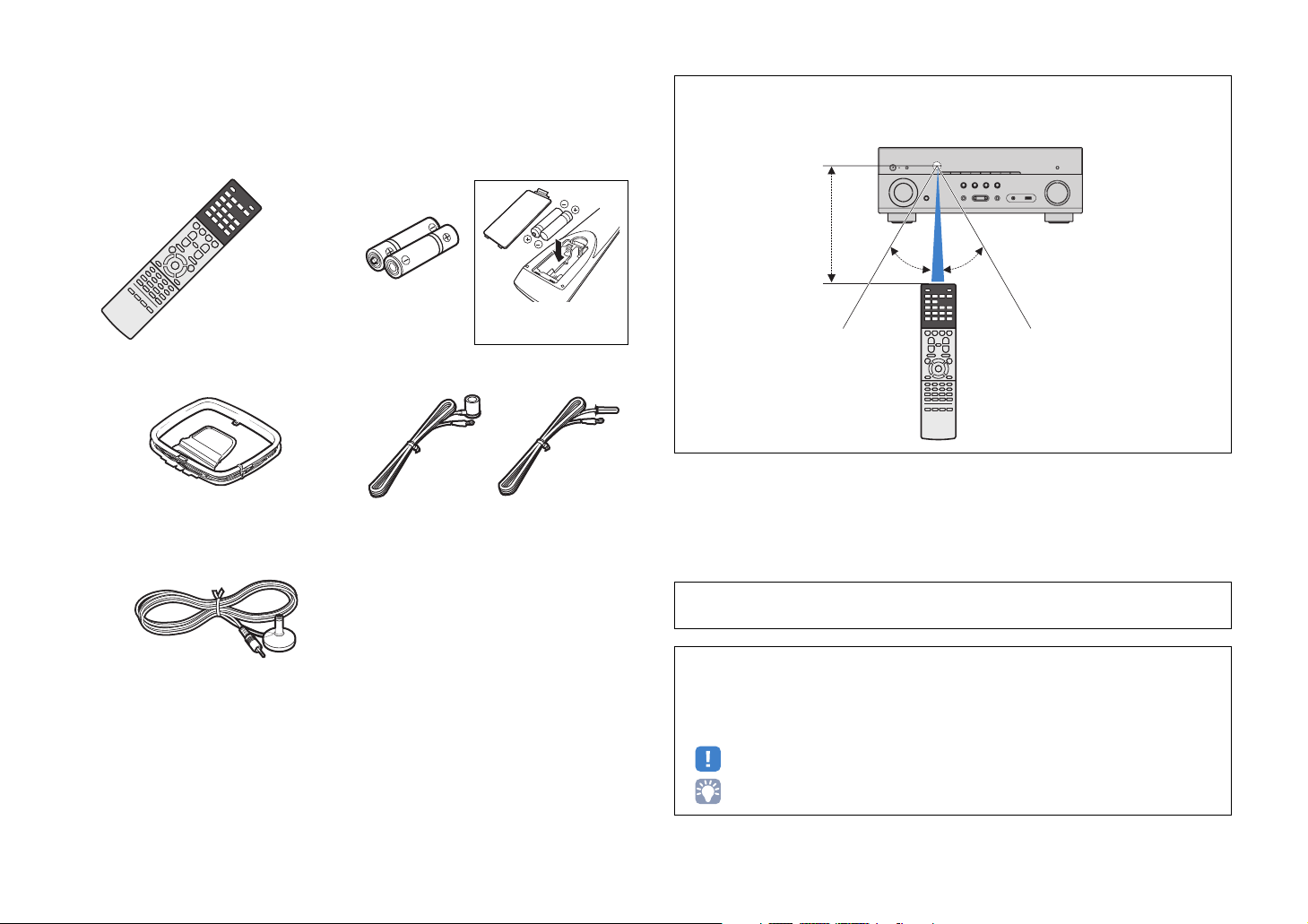
Accessories
Check that the following accessories are supplied with the product.
Remote control Batteries (AAA, R03, UM-4) (x2)
Insert the batteries the right
way round.
AM antenna FM antenna
*One of the above is supplied depending on the region of
purchase.
YPAO microphone
Operating range of the remote control
• Point the remote control at the remote control sensor on the unit and remain within the operating range
shown below.
Within 6 m (20 ft)
30° 30°
• The illustrations of the main unit used in this manual are of the U.S.A. model, unless otherwise
specified.
CD-ROM (Owner’s Manual)
Easy Setup Guide
Safety Brochure
En 4
• Some features are not available in certain regions.
• Due to product improvements, specifications and appearance are subject to change without notice.
• This manual explains operations using the supplied remote control.
• This manual describes all the “iPod” and “iPhone” as the “iPod”. “iPod” refers to both “iPod” and
“iPhone” unless otherwise specified.
• indicates precautions for use of the unit and its feature limitations.
• indicates supplementary explanations for better use.
Page 5
FEATURES
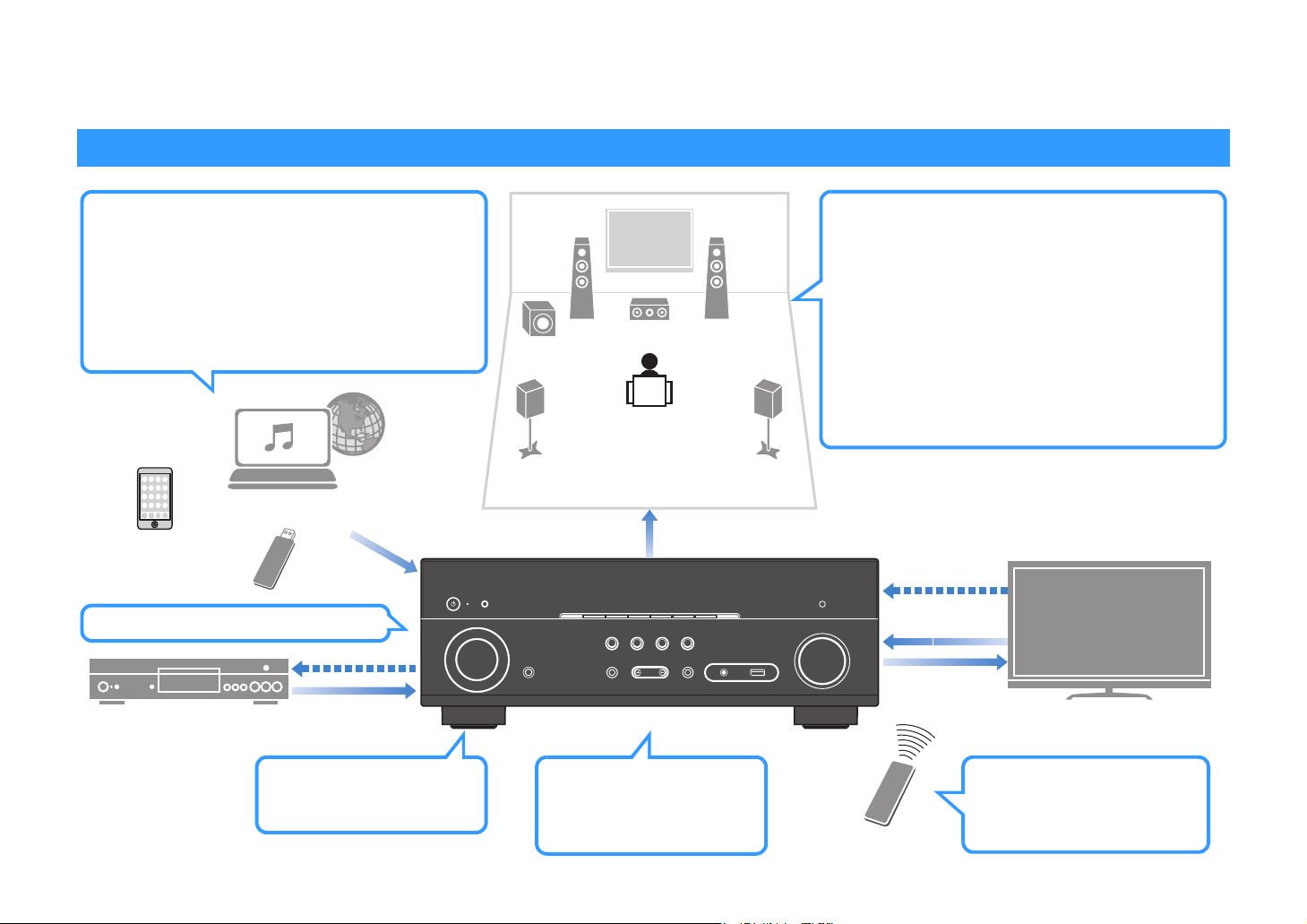
What you can do with the unit
Wide variety of supported content
• iPod/iPhone
•USB
• Media server (PC/NAS)
• Internet radio
•AirPlay
• BLUETOOTH
Network contents
BLUETOOTH
device
USB device
4K Ultra HD
signal and
BD/DVD player
HDCP 2.2
supported
HDMI Control
Audio/Video
. p.53
. p.58
. p.61
. p.64
. p.56
. p.52
Audio
Speakers
Audio
AV receiver (the unit)
Supports 2- to 5.1-channel speaker system.
Allows you to enjoy your favorite acoustic spaces
in various styles.
• Automatically optimizing the speaker
. p.27
settings to suit your room (YPAO)
• Reproducing stereo or multichannel
. p.44
sounds with the sound fields like
actual movie theaters and concert
halls (CINEMA DSP)
• Enjoying compressed music with
. p.47
enhanced sound (Compressed Music
Enhancer)
HDMI Control
Audio
Audio/Video
TV
Wireless connection to a
network
. p.24
Change the input source
and favorite settings with
one touch (SCENE)
. p.42
En 5
TV remote control
Sequential operation of a TV,
AV receiver, and BD/DVD
player (HDMI Control)
. p.107
Page 6

Full of useful functions!
About “AV SETUP GUIDE
”
About “AV CONTROLLER
”
❑ Connecting various devices (p.20)
A number of HDMI jacks and various input/output jacks
on the unit allow you to connect video devices (such as
BD/DVD players), audio devices (such as CD players),
game consoles, portable audio player, and other
devices.
❑ Playing back TV audio in surround sound
with a single HDMI cable connection
(Audio Return Channel: ARC) (p.18)
When using an ARC -compatible TV, you only need one
HDMI
cable to enable video output to the TV, audio input
HDMI
from the TV, and the transmission of
signals.
Control
❑ Creating 3-dimensional sound fields (p.44)
The Virtual Presence Speaker (VPS) function allows you
to create a 3-dimensional sound field that spreads up
and deep in your own room (CINEMA DSP 3D).
❑ Surround playback with 5 speakers placed
in front (p.45)
You can enjoy the surround sound even when the
surround speakers are placed in front.
❑ Enjoying pure high fidelity sound (p.47)
When the direct playback mode is enabled, the unit
plays back the selected source with the least circuitry,
which lets you to enjoy Hi-Fi sound quality.
❑ Application for tablets “AV SETUP GUIDE”
AV SETUP GUIDE is an application that
assists you with cable connections
between AV receiver and source
devices as well as AV receiver setup.
This app guides you through the various
settings such as speaker connections,
TV and source device connections.
Functions:
1) Connection support guide
– Speaker connection
– TV/source devices connection
2) Setup support guide
– Various setup assistance with illustrations.
– YPAO setting guidance
3) View owner’s manual
* This application is for tablets only.
For details, search for “AV SETUP GUIDE” on the App
Store or Google Play.
❑ Application for smartphone / tablets “AV
CONTROLLER”
AV CONTROLLER provides you the
flexibility to control the available inputs,
volume, mute and power commands. It
lets users change a song from Internet
Radio, USB and command FM/AM
tuners or any other internally available
source.
Functions:
– Power on/off
– Volume up/down
–Mute
– Music Play
– Input Selection
– DSP Mode Selection
– SCENE selection
– Blu-ray player fundamental control
– Seamless control between the Yamaha AV receiver
and Blu-ray player
– Demo mode - Explains how to use this app
For details, search for “AV CONTROLLER” on the App
Store or Google Play.
❑ Low power consumption
The ECO mode (power saving function) reduces the
unit’s power consumption and helps to create an
eco-friendly home theater system (p.82).
En 6
Page 7
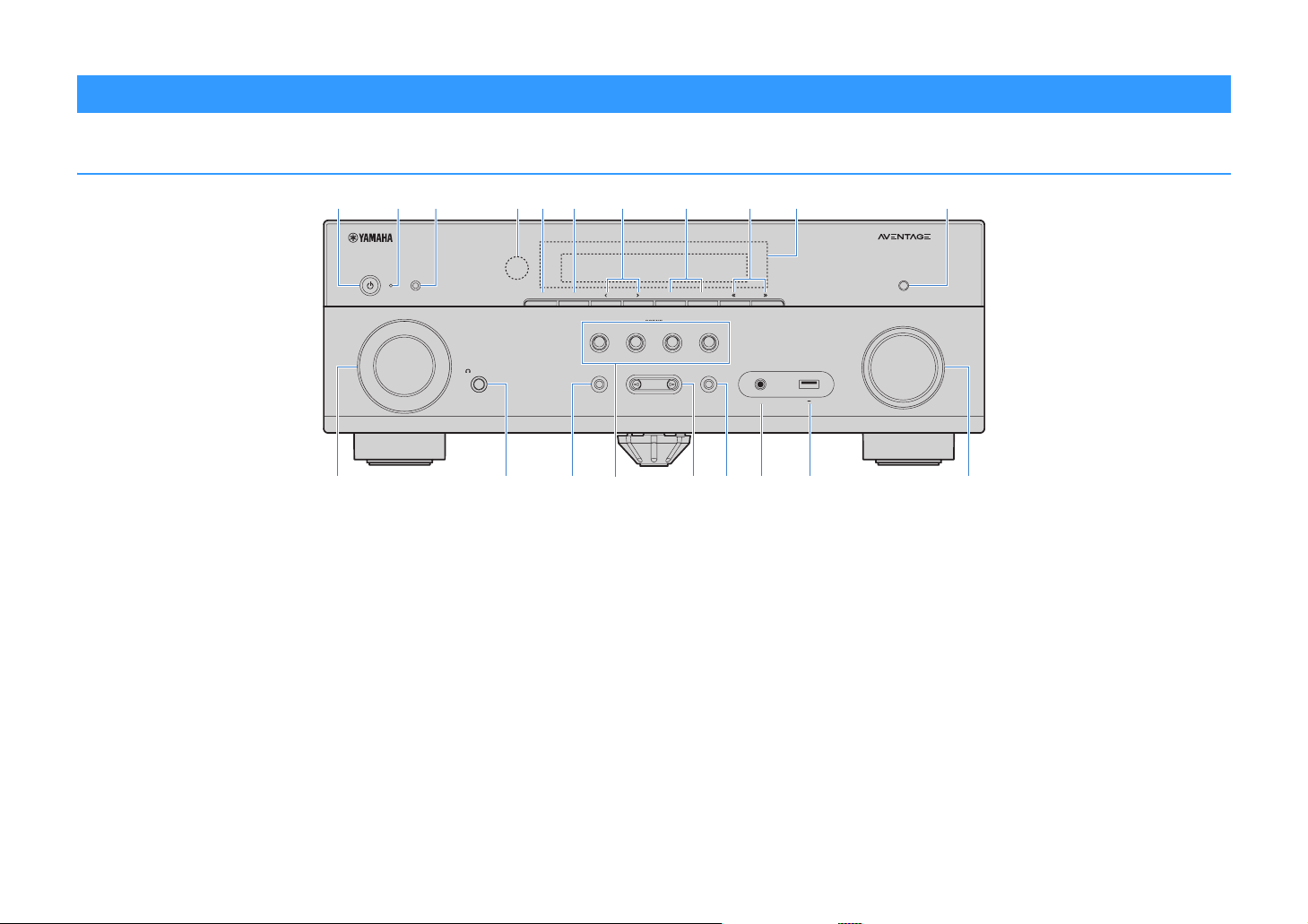
Part names and functions
Front panel
b cdfgheaji k
lmnoprstq
1 z (power) key
Turns on/off (standby) the unit.
2 Standby indicator
Lights up when the unit is in standby mode under any of the
following conditions.
• HDMI Control is enabled (p.78)
• Standby Through is enabled (p.78)
• Network Standby is enabled (p.86)
• An iPod is being charged (p.53)
3 YPAO MIC jack
For connecting the supplied YPAO microphone (p.27).
4 Remote control sensor
Receives remote control signals (p.4).
5 INFO (WPS) key
Selects the information displayed on the front display (p.68).
Enters the wireless LAN connection setup (WPS button
configuration) by holding down for 3 seconds (p.34).
YPAO MIC
INFO (WPS)
MEMORY
INPUT
PHONES
SILENT CINEMA
TONE CONTROL
FM
PRESET
SCENE
NET
TVBD/DVD
PROGRAM
AM
RADIO
STRAIGHT
(CONNECT)
TUNING
AUX
5V 1A
AUDIO
6 MEMORY key
Registers FM/AM radio stations as preset stations (p.49).
7 PRESET keys
Select a preset FM/AM radio station (p.50).
8 FM and AM keys
Switch between FM and AM (p.48).
9 TUNING keys
Select the radio frequency (p.48).
0 Front display
Displays information (p.8).
A DIRECT key
Enables/disables the direct playback mode (p.47).
B INPUT keys
Select an input source.
C PHONES jack
For connecting headphones.
DIRECT
VOLUME
D TONE CONTROL key
Adjusts the high-frequency range and low-frequency range
of output sounds (p.70).
E SCENE keys
Select the registered input source and sound program with
one touch. Also, turns on the unit when it is in standby mode
(p.42).
F PROGRAM keys
Select a sound program or a surround decoder (p.43).
G STRAIGHT key
Enables/disables the straight decode mode (p.46).
H AUX jack
For connecting devices, such as portable audio players
(p.23).
I USB jack
For connecting a USB storage device (p.58) or an iPod
(p.53).
J VOLUME knob
Adjusts the volume.
En 7
Page 8
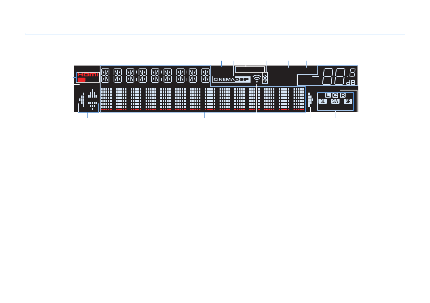
Front display (indicators)
a
CHARGE
1 2
OUT
ECO
ji ljkmn
1 HDMI
Lights up when HDMI signals are being input or output.
OUT
Lights up when HDMI signals are being output.
2 ENHANCER
Lights up when Compressed Music Enhancer (p.47) is
working.
3 CINEMA DSP
Lights up when CINEMA DSP (p.44) or CINEMA DSP 3D
(p.44) is working.
4 STEREO
Lights up when the unit is receiving a stereo FM radio signal.
TUNED
Lights up when the unit is receiving an FM/AM radio station
signal.
5 BLUETOOTH indicator
Light up while the unit is connecting to a BLUETOOTH
device.
6 SLEEP
Lights up when the sleep timer is on.
bc d
ENHANCER
7 MUTE
Blinks when audio is muted.
8 Volume indicator
Indicates the current volume.
9 ECO
Lights up when the eco mode (p.82) is enabled.
0 Cursor indicators
Indicate the remote control cursor keys currently operational.
A Information display
Displays the current status (such as input name and sound
mode name). You can switch the information by pressing
INFO (p.68).
B Signal strength indicator
Indicates the strength of the wireless signal (p.31).
STEREO
TUNED
e
PARTY
23
fg h
SLEEP
MUTE
VOL.
ADAPTIVE DRC
C Speaker indicators
Indicate speaker terminals from which signals are output.
A Front speaker (L)
S Front speaker (R)
D Center speaker
F Surround speaker (L)
G Surround speaker (R)
L Subwoofer
D ADAPTIVE DRC
Lights up when Adaptive DRC (p.70) is working.
VIRTUAL
En 8
Page 9
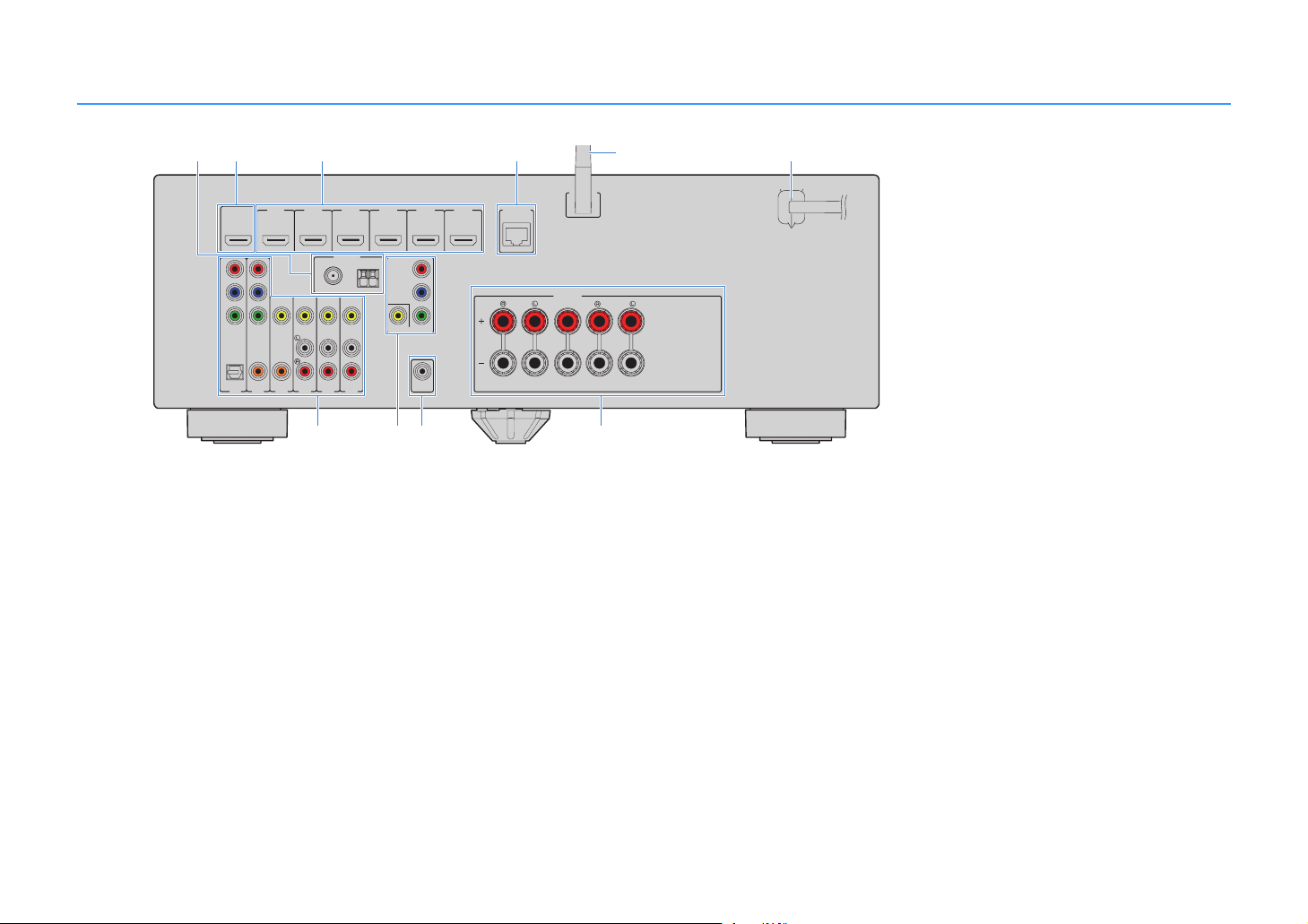
Rear panel
ab cd f
HDMIOUT
HDCP2.2
P
R
P
B
Y
COMPONENT
VIDEO
OPTICAL
(TV)
AV1
HDMI1
HDMI2
(BD/DVD)
ARC
VIDEO
COAXIAL
COAXIAL
AV2
AV5
AV4
AV3
FM
75Ω
HDMI3
ANTENNA
(RADIO)
HDMI4
AM
AV6
gh
1 ANTENNA jacks
For connecting to FM and AM antennas (p.23).
2 HDMI OUT jack
For connecting to an HDMI-compatible TV and outputting
video/audio signals (p.18). When using ARC, TV audio signal
can also be input through the HDMI OUT jack.
3 HDMI 1–6 jacks
For connecting to HDMI-compatible playback devices and
inputting video/audio signals (p.20).
4 NETWORK jack
For a wired connection to a network (p.24).
5 Wireless antenna
For a wireless (Wi-Fi) connection to a network (p.24).
6 Power cable
For connecting to an AC wall outlet (p.25).
7 AV jacks
For connecting to video/audio playback devices and
inputting video/audio signals (p.20).
8 MONITOR OUT jacks
For connecting to a TV and outputting video signals (p.18).
COMPONENT
VIDEO
MONITOROUT
e
N
ETWORK
HDMI6
HDMI5
HDCP2.2
P
R
P
B
Y
SUBWOOFER
PREOUT
(NET)
FRONT
WSS
SPEAKERS
CENTER
CLASS2WIRINGCABLAGECLASSE2
SURROUND
ji
9 SUBWOOFER PRE OUT jack
For connecting to a subwoofer (with built-in amplifier) (p.15).
0 SPEAKERS terminals
For connecting to speakers (p.15).
(U.S.A. model)
* The area around the video/audio output jacks is
marked in white on the actual product to prevent
improper connections.
En 9
Page 10
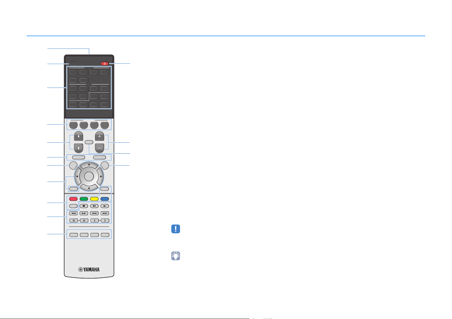
Remote control
a
b
c
d
e
f
g o
SLEEP
HDMI
123 4
5 6
AV
123 4
56
BLUETOOTH
BD
DVD
PROGRAM VOLUME
SETUP OPTION
TOP MENU
TV
SCENE
MUTE
ENTER
FM AM
NET
NET
POP-UP/MENU
AUXUSB
RADIO
l
m
n
h
DISPLAY
YELLOWGREEN
BLUE
MEMORY
i
j
RETURN
RED
HOME
TUNING PRESET
1 Remote control signal transmitter
Transmits infrared signals.
2 SLEEP key
Switches the unit to standby mode automatically after a
specified period of time has elapsed (sleep timer). Press
repeatedly to set the time (120 min, 90 min, 60 min, 30 min,
off).
3 Input selection keys
Select an input source for playback.
You can select directly each input source by pressing the
following keys.
HDMI 1-6 HDMI 1-6 jacks
AV 1-6 AV 1-6 jacks
FM Switches to FM radio.
AM Switches to AM radio.
BLUETOOTH BLUETOOTH device
USB USB jack (on the front panel)
NET SERVER, NET RADIO, AirPlay and network
sources (press repeatedly to select a desired
source)
AUX AUX jack (on the front panel)
4 SCENE keys
Select the registered input source and sound program with
one touch. Also, turn on the unit when it is in standby mode
(p.42).
5 PROGRAM keys
Select a sound program (p.43).
6890 External device operation keys
Let you perform playback operations when “USB” or “NET”
is selected as the input source, or control playback of the
HDMI Control-compatible playback device.
8 Menu operation keys
Cursor keys Select a menu or a parameter.
ENTER Confirms a selected item.
RETURN Returns to the previous screen.
0 Radio keys
Operate the FM/AM radio when “TUNER” is selected as the
input source (p.48).
MEMORY Registers FM/AM radio stations as presets.
PRESET Select a preset station.
TUNING Select the radio frequency.
A Sound mode keys
Select a sound mode (p.43).
B z (receiver power) key
Turns on/off (standby) the unit.
C VOLUME keys
Adjust the volume.
D MUTE key
Mutes the audio output.
E OPTION key
Displays the option menu (p.69).
k
STRAIGHT DIRECT ENHANCER BASS
RAV546
ZQ56680
• The playback devices must support HDMI Control. However,
Yamaha does not assure the operation of all HDMI
Control-compatible devices.
• You can assign the unit's functions to the RED/GREEN/
YELLOW/BLUE keys (p.84).
7 SETUP key
Displays the setup menu (p.72).
En 10
Page 11

PREPARATIONS
General setup procedure
1 Placing speakers (p.12)
2 Connecting speakers (p.15)
3 Connecting a TV (p.18)
4 Connecting playback devices (p.20)
5 Connecting the FM/AM antennas (p.23)
Preparing for connecting to a network
6
(p.24)
7 Connecting the power cable (p.25)
Selecting an on-screen menu language
8
(p.26)
Optimizing the speaker settings
9
automatically (YPAO) (p.27)
Select the speaker layout for the number of speakers that you are using and place them in your room.
Connect the speakers to the unit.
Connect a TV to the unit.
Connect video devices (such as BD/DVD players) and audio devices (such as CD players) to the unit.
Connect the supplied FM/AM antennas to the unit.
Connect the unit to a network with a commercially-available network cable.
After all the connections are complete, plug in the power cable.
Select the desired on-screen menu language.
Optimize the speaker settings, such as volume balance and acoustic parameters, to suit your room
(YPAO).
10 Connecting to a network wirelessly (p.31)
This completes all the preparations. Enjoy playing movies, music, radio and other content with the unit!
Connect the unit to a network wirelessly.
En 11
Page 12
1 2 3 4 5 6 7 8 9 10
1 Placing speakers
Select the speaker layout for the number of speakers that you are using and place the speakers and subwoofer in your room. This section describes the representative speaker layout
examples.
Caution
• (U.S.A. and Canada models only)
Under its default settings, the unit is configured for 8-ohm speakers. When connecting 6-ohm speakers, set the unit’s speaker impedance to “6 Ω MIN”. For details, see “Setting the speaker impedance” (p.14).
• (Except for U.S.A. and Canada models)
Use speakers with an impedance of at least 6 Ω.
• Use a subwoofer with built-in amplifier.
• Be sure to connect the front left and right speakers.
Speaker system (the number of channels)
Speaker type Abbr. Function
Front (L) 1
Front (R) 2 ●●●●●
Center 3 Produces center channel sounds (such as movie dialogue and vocals). ●● ●
Surround (L) 4
Surround (R) 5 ●●* ●
Subwoofer 9
Produce front left/right channel sounds (stereo sounds).
Produce surround left/right channel sounds.
Produces LFE (low-frequency effect) channel sounds and reinforces the bass parts of other channels.
This channel is counted as “0.1”.
5.1
●●●●●
●●* ●
●●●●●
5.1
Virtual
(
CINEMA
FRONT
4.1 3.1 2.1
)
* Place the surround speakers in front and set “Virtual CINEMA FRONT” (p.76) in the “Setup” menu to “On”.
En 12
Page 13
1 2 3 4 5 6 7 8 9 10
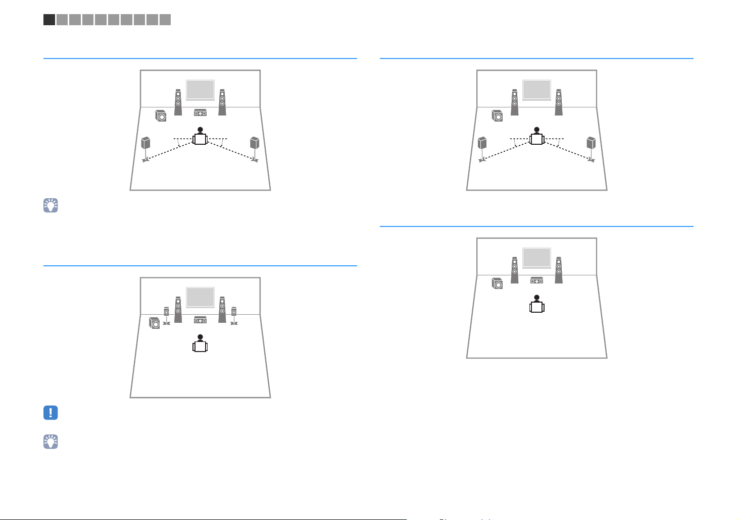
5.1-channel system
12
39
45
10° to 30°10° to 30°
• You can enjoy surround sound even without the center speaker (front 4.1-channel system).
• You can place the subwoofer either in the left or right side.
5.1-channel system (
Virtual CINEMA FRONT
12
45
39
)
4.1-channel system
12
9
45
10° to 30°10° to 30°
3.1-channel system
12
39
• To utilize this configuration, set “Virtual CINEMA FRONT” (p.76) in the “Setup” menu to “On”.
• You can enjoy surround sound even without the center speaker (front 4.1-channel system).
• You can place the subwoofer either in the left or right side.
En 13
Page 14
1 2 3 4 5 6 7 8 9 10
2.1-channel system
12
9
■ Setting the speaker impedance
(U.S.A. and Canada models only)
Under its default settings, the unit is configured for 8-ohm speakers. When connecting
6-ohm speakers, set the speaker impedance to “6 Ω MIN”.
Before connecting speakers, connect the power cable to an AC wall
1
outlet.
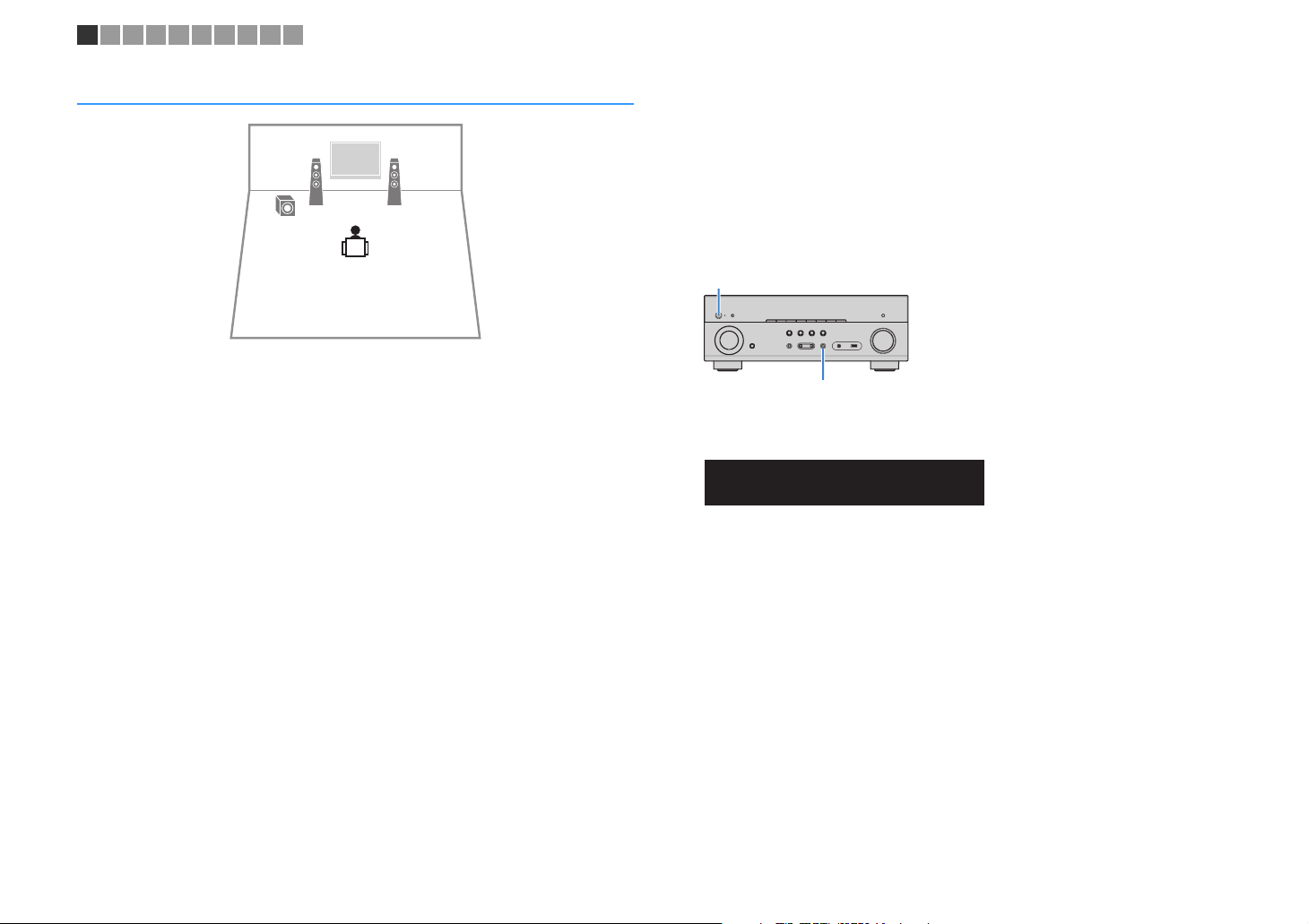
While holding down STRAIGHT on the front panel, press z (power).
2
z (power)
STRAIGHT
Check that “SP IMP.” is displayed on the front display.
3
SLEEP
CHARGE
OUT
ECO
1 2
ENHANCER
STEREO
TUNED
PARTY
ZONE2AZONE
MUTE
3B
VOL.
VIRTUAL
ADAPTIVE DRC
SP IMP.••8¬MIN
Press STRAIGHT to select “6 Ω MIN”.
4
Press z (power) to set the unit to standby mode and remove the
5
power cable from the AC wall outlet.
You are now ready to connect the speakers.
En 14
Page 15
Y
SUBWOOFER
PREOUT
FRONT
CENTER
SURROUND
SPEAKERS
CLASS2WIRINGCABLAGECLASSE2
B
FRONT
FRONT
1 2 3 4 5 6 7 8 9 10
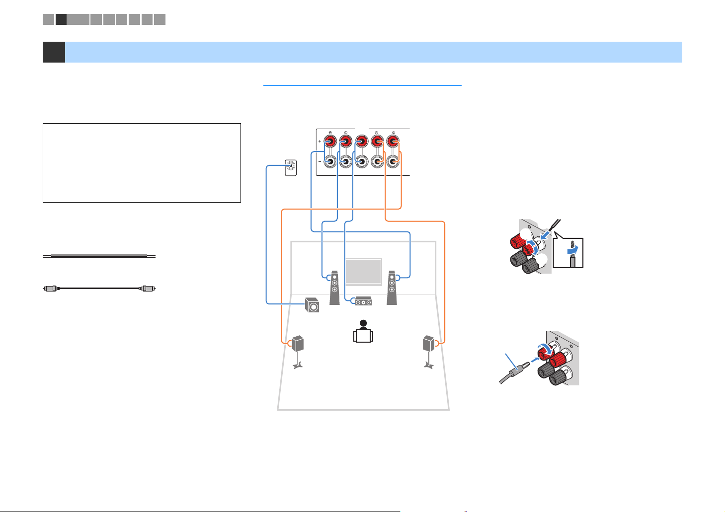
2 Connecting speakers
Connect the speakers placed in your room to the unit.
The following diagrams provide connections for
5.1-channel system as an example. For other systems,
connect speakers while referring to the connection
diagram for the 5.1-channel system.
Caution
• Remove the unit’s power cable from an AC wall outlet and turn
off the subwoofer before connecting the speakers.
• Ensure that the core wires of the speaker cable do not touch
one another or come into contact with the unit’s metal parts.
Doing so may damage the unit or the speakers. If the speaker
cables short circuit, “Check SP Wires” will appear on the front
display when the unit is turned on.
Cables required for connection
(commercially available)
Speaker cables (x the number of speakers)
+
–
+
–
Audio pin cable (x1: for connecting a subwoofer)
5.1-channel system
■ Connecting speaker cables
Speaker cables have two wires. One is for connecting
the negative (-) terminal of the unit and the speaker, and
the other is for the positive (+) terminal. If the wires are
The unit (rear)
colored to prevent confusion, connect the black wire to
the negative and the other wire to the positive terminal.
a Remove approximately 10 mm (3/8”) of insulation from
b Loosen the speaker terminal.
c Insert the bare wires of the cable into the gap on the side
d Tighten the terminal.
+ (red)
12
9
3
- (black)
Using a banana plug
(U.S.A., Canada, China and Australia models only)
a Tighten the speaker terminal.
b Insert a banana plug into the end of the terminal.
45
Banana plug
the ends of the speaker cable and twist the bare wires of
the cable firmly together.
(upper right or bottom left) of the terminal.
c
b
aa
d
a
b
En 15
Page 16

1 2 3 4 5 6 7 8 9 10
■ Connecting the subwoofer
(with built-in amplifier)
Use an audio pin cable to connect the subwoofer.
Audio pin cable
AV 6
En 16
Page 17
1 2 3 4 5 6 7 8 9 10
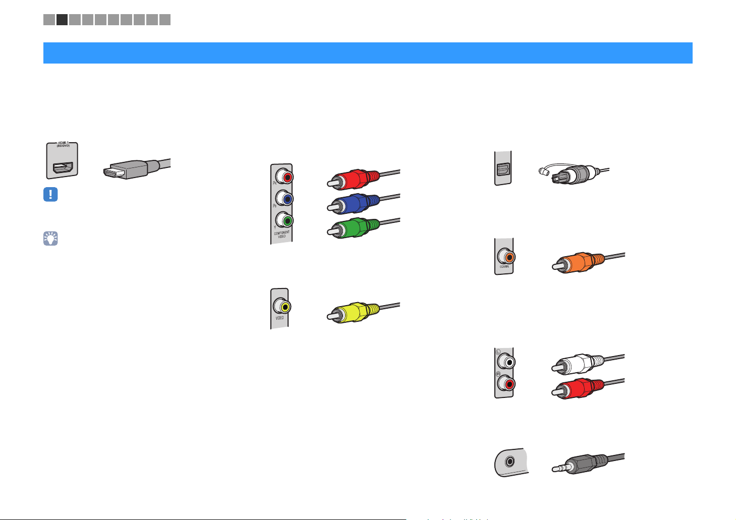
Input/output jacks and cables
■ Video/audio jacks
❑ HDMI jacks
Transmit digital video and digital sound through a single
jack. Use an HDMI cable.
HDMI cable
• Use a 19-pin HDMI cable with the HDMI logo. We recommend using
a cable less than 5.0 m (16.4 ft) long to prevent signal quality
degradation.
• The unit’s HDMI jacks support the HDMI Control, Audio Return
Channel (ARC), and 3D and 4K Ultra HD video transmission
(through output) features.
• Use high speed HDMI cables to enjoy 3D or 4K Ultra HD videos.
■ Video jacks
❑ COMPONENT VIDEO jacks
Transmit video signals separated into three
components: luminance (Y), chrominance blue (P
and chrominance red (P
cable with three plugs.
R). Use a component video
Component video cable
❑ VIDEO jacks
Transmit analog video signals. Use a video pin cable.
Video pin cable
B),
■ Audio jacks
❑ OPTICAL jacks
Transmit digital audio signals. Use a digital optical
cable. Remove the tip protector (if available) before
using the cable.
Digital optical cable
OPTICAL
❑ COAXIAL jacks
Transmit digital audio signals. Use a digital coaxial
cable.
Digital coaxial cable
❑ AUDIO jacks
(Stereo L/R jacks)
Transmit analog stereo audio signals. Use a stereo pin
cable (RCA cable).
Stereo pin cable
En 17
(Stereo mini jack)
Transmits analog stereo audio signals. Use a stereo
mini-plug cable.
Stereo mini-plug cable
Page 18
AV5
A
V4
AV3
AV2
CO
AXIAL
COAX
I
A
L
VIDEO
COMP
ONE
NT
VI
DEO
Y
P
B
P
R
FM
75Ω
ANT
(R
HDM
I
2
HDMI1
(
BD/DVD)
HDMIOUT
HD
CP2.2
ARC
AV1
O
PTICAL
(TV)
1 2 3 4 5 6 7 8 9 10
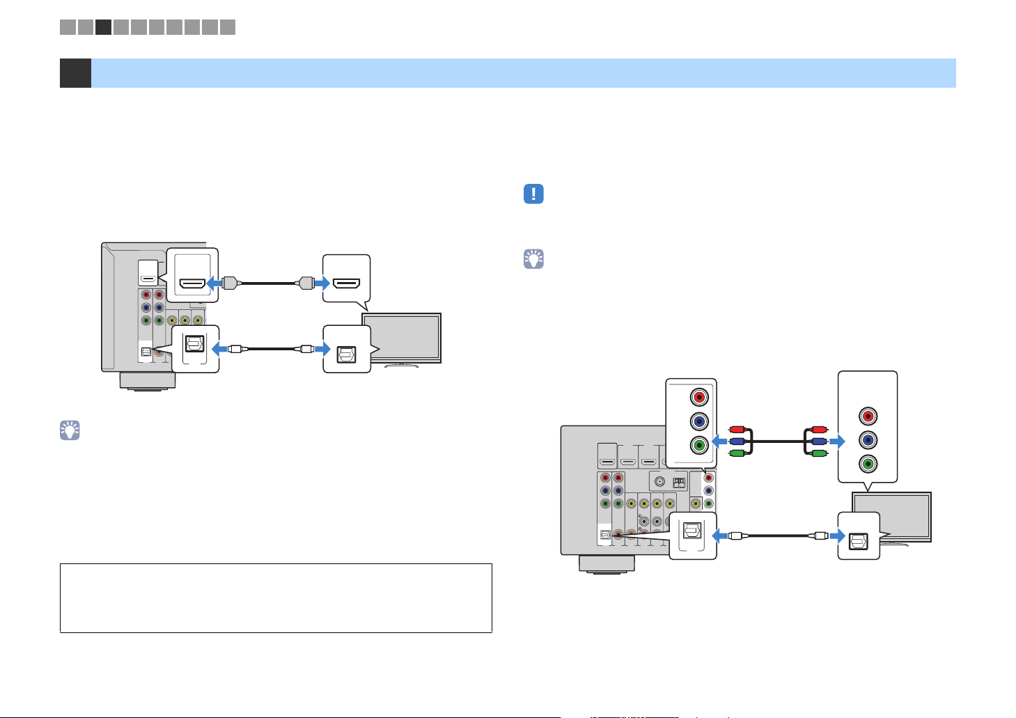
3 Connecting a TV
Connect a TV to the unit so that video input to the unit can be output to the TV. You can
also enjoy playback of TV audio on the unit.
To maximize the performance of the unit, we recommend connecting a TV with an HDMI
cable.
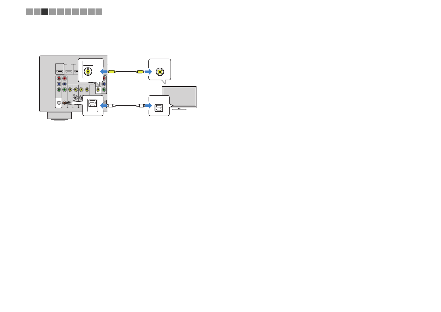
■ HDMI connection
Connect the TV to the unit with an HDMI cable and a digital optical cable.
The unit (rear)
HDMI OUT jack
OUT
HDMI
HDCP2.2
ARC
HDMI
OPTICAL
(TV)
AV 1
OO
AV 1 (OPTICAL) jack
• You do not make a digital optical cable connection between the TV and the unit in the following cases:
– If your TV supports Audio Return Channel (ARC)
– If you will receive TV broadcasts only from the set-top box
• If you connect a TV that supports HDMI Control to the unit with an HDMI cable, you can control the unit’s
power and volume with the TV’s remote control.
To use HDMI Control and ARC, you need to configure the HDMI settings on the unit. For
details on the settings, see “Information on HDMI” (p.107).
About Audio Return Channel (ARC)
• ARC allows audio signals to travel both ways. If you connect a TV that supports ARC to the unit with a
single HDMI cable, you can output video/audio to the TV or input TV audio to the unit.
• When using ARC, connect a TV with an HDMI cable that supports ARC.
HDMI input
HDMI
HDMI
OPTICAL
Audio output
(digital optical)
TV
■ Component / composite video connection
When connecting any video device with a component video cable, connect the TV to
the MONITOR OUT (COMPONENT VIDEO) jacks.
When connecting any video device with a video pin cable, connect the TV to the
MONITOR OUT (VIDEO) jack.
• If you connect your TV to the unit with a cable other than HDMI, video input to the unit via HDMI cannot be
output to the TV.
• Operations with TV screen are available only when your TV is connected to the unit via HDMI.
• If you will receive TV broadcasts only from the set-top box, you do not need to make an audio cable
connection between the TV and the unit.
❑ COMPONENT VIDEO connection
Connect the TV to the unit with a component video cable and a digital optical cable.
Video input
(component video)
COMPONENT
VIDEO
PR
PB
P
R
P
B
Y
Y
OPTICAL
O
Audio output
(digital optical)
TV
The unit (rear)
HDMIOUT
HD
CP2.
ARC
P
R
P
B
Y
COMPONE
VIDEO
O
PTICAL
(TV)
AV1
MONITOR OUT
(COMPONENT VIDEO) jacks
COMPONENT
VIDEO
PR
PB
MI3
MONITOR OUT
IO)
A
M
AV6
HDMI4
Y
COMPONENT
OPTICAL
(TV)
AV 1
HDMI5
VIDEO
P
R
P
B
Y
MON
IT
OR
OUT
SUBWOO
PREOUT
HDMI1
(
2
NT
COA
XI
A
L
AV2
HD
HDM
I2
BD/DVD)
ANTENNA
(RAD
FM
75
Ω
VIDEO
COAXIAL
AV5
AV
4
AV3
AV 1 (OPTICAL) jack
P
R
P
B
Y
O
F
ER
En 18
Page 19
1 2 3 4 5 6 7 8 9 10
❑ VIDEO (composite video) connection
Connect the TV to the unit with a video pin cable and a digital optical cable.
The unit (rear)
HD
MIOUT
HD
CP2.
2
ARC
P
R
P
B
Y
C
OMPONE
NT
VIDEO
O
PTICAL
(TV)
AV1
MONITOR OUT
(VIDEO) jack
HD
HDM
HDMI1
(
BD/DVD)
COA
XI
A
L
AV2
MI3
I2
ANTENNA
(RAD
IO)
FM
MONITOR OUT
75
Ω
VIDEO
COAXIAL
AV6
AV5
AV
4
AV3
AV 1 (OPTICAL) jack
A
M
OPTICAL
(TV)
AV 1
Video input
(composite video)
HDMI4
COMPONENT
HDMI5
V
VIDEO
P
R
P
B
Y
MON
IT
OR
OUT
VIDEO
V
OPTICAL
O
SUBWOO
FER
PREOUT
O
TV
Audio output
(digital optical)
En 19
Page 20
AV
6
AV5
AV4
AV
3
AV2
AV
1
OPTICAL
(TV)
COA
XIAL
CO
AXIAL
VID
EO
COMPONENT
VIDEO
Y
P
B
P
R
FM
75Ω
ANTENNA
(RADIO
)
HDMI2
HDMI3
HDMI1
(BD/DVD)
HDMIOUT
HDCP2.2
ARC
1 2 3 4 5 6 7 8 9 10
4 Connecting playback devices
The unit is equipped with a variety of input jacks including HDMI input jacks to allow
you to connect different types of playback devices. For information on how to connect a
BLUETOOTH device, an iPod, or a USB storage device, see the following pages.
– Connecting a BLUETOOTH device (p.52)
– Connecting an iPod (p.53)
– Connecting a USB storage device (p.58)
Connecting video devices (such as BD/
DVD
players)
Connect video devices such as BD/DVD players, set-top boxes (STBs) and game
consoles to the unit. Depending on the video/audio output jacks available on your video
device, choose one of the following connections. We recommend using an HDMI
connection if the video device has an HDMI output jack.
• If the combination of video/audio input jacks available on the unit does not match your video device, change
its combination according to the output jacks of your device (p.21).
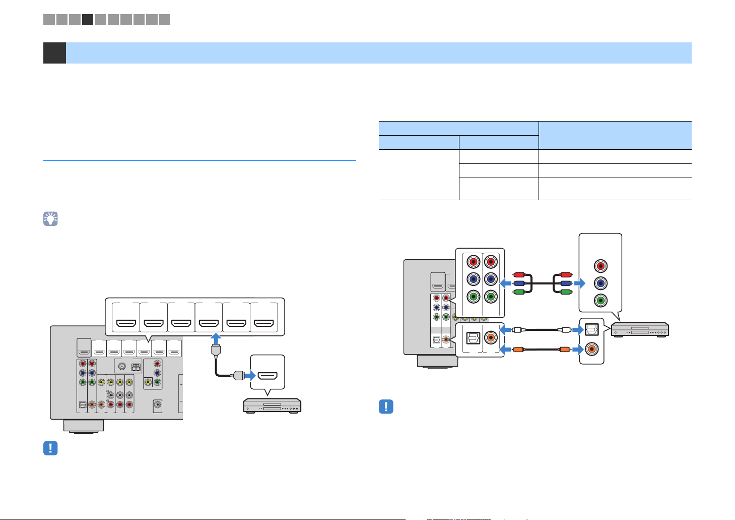
■ HDMI connection
Connect a video device to the unit with an HDMI cable.
HDMI 1–6 jacks
HDMI 1
The unit (rear)
HDMIOUT
HD
CP2.
2
ARC
P
R
P
B
Y
COMPONE
NT
VIDEO
HDMI 2 HDMI 3 HDMI 4
(
)
BD/DVD
HDMI5
HD
HDMI4
COMPONENT
HDMI6
HDCP2
.2
VIDEO
P
R
P
B
Y
MON
IT
OR
OUT
HDMI1
HDM
MI3
I2
(
BD/DVD)
ANTENNA
(RAD
IO)
FM
A
M
75
Ω
VIDEO
HDMI
HDMI 5 HDMI 6
HDCP2.2
HDMI output
HDMI
HDMI
■ Component video connection
Connect a video device to the unit with a component video cable and an audio cable
(digital optical or digital coaxial). Choose a set of input jacks (on the unit) depending on
the audio output jacks available on your video device.
Output jacks on video device
Video Audio
Component video
AV 1-2 (COMPONENT VIDEO) jacks
The unit (rear)
AV 1 (OPTICAL) jack or
AV 2 (COAXIAL) jack
Digital optical AV 1 (COMPONENT VIDEO + OPTICAL)
Digital coaxial AV 2 (COMPONENT VIDEO + COAXIAL)
Analog Stereo
P
R
P
B
Y
COMPONENT
VIDEO
R
P
P
B
Y
O
OPTICAL
COAXIAL
( TV )
AV 1
C
AV 2
(digital optical or digital coaxial)
Input jacks on the unit
You need to change the combination of
video/audio input jacks (p.21).
Video output
(component video)
COMPONENT
VIDEO
PR
R
P
PB
P
B
Y
Y
O
OPTICAL
C
COAXIAL
Video device
Audio output
O
PTICAL
COA
COAXIAL
XI
A
L
(TV)
AV1
• If you connect a video device to the unit via HDMI, you need to connect your TV to the HDMI OUT jack of
• For the HDCP 2.2-compatible HDMI device, use the HDMI 6 jack to connect it.
the unit (p.18).
AV5
AV
AV2
4
AV3
SUBWOO
F
ER
PREOUT
AV6
Video device
• If you connect a video device to the unit via component video connection, you need to connect your TV to
the MONITOR OUT (COMPONENT VIDEO) jacks of the unit (p.18).
En 20
Page 21
U
W
E
1 2 3 4 5 6 7 8 9 10
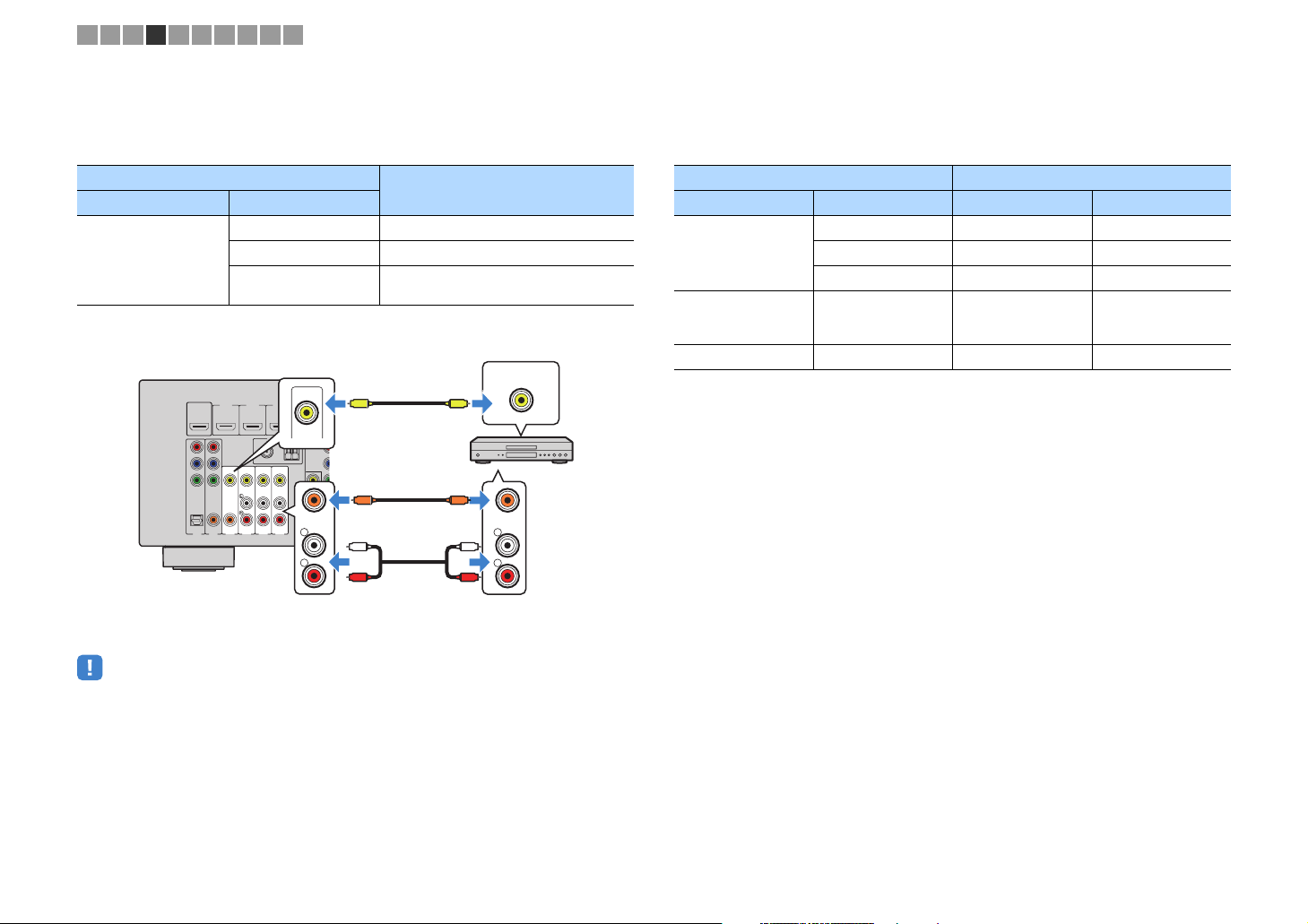
■ Composite video connection
Connect a video device to the unit with a video pin cable and an audio cable (digital
coaxial or stereo pin cable). Choose a set of input jacks (on the unit) depending on the
audio output jacks available on your video device.
Output jacks on video device
Video Audio
Composite video
AV 3–6 (VIDEO) jacks
HDMIOUT
HDMI1
(
HD
BD/DVD)
CP2.
2
ARC
P
R
P
B
Y
VIDEO
COMPONE
NT
VIDEO
O
PTICAL
COA
COAXIAL
XI
A
L
(TV)
AV
AV2
AV3
AV1
The unit (rear)
AV 3 (COAXIAL) jack or
Digital coaxial AV 3 (VIDEO + COAXIAL)
Analog stereo AV 4–6 (VIDEO + AUDIO)
Digital optical
V
H
HD
HDMI4
HDM
MI3
I2
VIDEO
ANTENNA
(RAD
IO)
COMPONENT
FM
A
M
VIDEO
P
75
AV5
4
R
Ω
P
B
Y
MON
IT
OR
O
COAXIAL
L
AV6
R
CC
SUB
PR
L
R
AV 4–6 (AUDIO) jacks
Input jacks on the unit
You need to change the combination of
video/audio input jacks (p.21).
Video output
(composite video)
VIDEO
V
Video device
COAXIAL
L
L
R
R
Audio output
(digital coaxial or analog stereo)
■ Changing the combination of video/audio input jacks
If the combination of video/audio input jacks available on the unit does not match your
video device, change its combination according to the output jacks of your device. You
can connect a video device that has the following video/audio output jacks.
Output jacks on video device Input jacks on the unit
Video Audio Video Audio
Digital optical HDMI 1–6 AV 1 (OPTICAL)
HDMI
Component video Analog stereo
Composite video Digital optical AV 3–6 (VIDEO) AV 1 (OPTICAL)
Digital coaxial HDMI 1–6 AV 2–3 (COAXIAL)
Analog stereo HDMI 1–6 AV 4–6 (AUDIO)
AV 1–2
(COMPONENT
AV 4–6 (AUDIO)
VIDEO)
• If you connect a video device to the unit via composite video connection, you need to connect your TV to
the MONITOR OUT (VIDEO) jack of the unit (p.19).
En 21
Page 22
SETU
P
UPOP-UP/
U
Y
RETURN
1 2 3 4 5 6 7 8 9 10
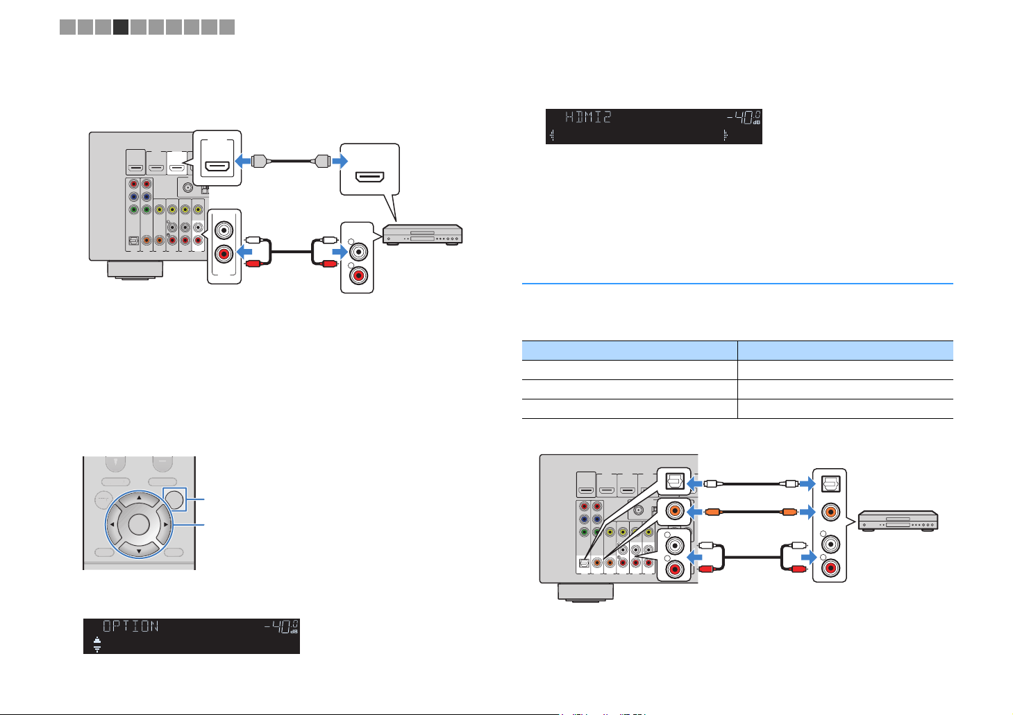
❑ Necessary setting
For example, if you have connected a video device to HDMI 2 and AV 6 (AUDIO) jack
of the unit, change the combination setting as follows.
The unit (rear)
HDMIOUT
HD
CP2.
2
ARC
P
R
P
B
Y
COMPONE
NT
VIDEO
O
PTICAL
COA
XI
A
(TV)
AV2
AV1
After connecting external devices (such as a TV and playback
1
devices) and power cable of the unit, turn on the unit.
Press INPUT to select “HDMI 2” (video input jack to be used) as the
2
input source.
Press OPTION.
3
HDMI 2 jack
HDMI1
HDM
I2
(
BD/DVD)
ANTENNA
FM
75
Ω
VIDEO
COAXIAL
L
AV5
AV4
AV3
AV 6 (AUDIO) jack
HDMI2
HD
MI3
(RAD
IO)
A
M
AV6
HDMI
L
R
AV 6
HDMI output
HDMI
HDMI
AUDIO
L
L
R
R
Audio output
(analog stereo)
Video device
Use the cursor keys (e/r) to select “
5
AV 6
” (audio input jack to be
used).
CHARGE
OUT
ECO
ENHANCER
STEREO
TUNED
SLEEP
MUTE
VOL.
ADAPTIVE DRC
VIRTUAL
Audio••••••AV6
Press OPTION.
6
This completes the necessary settings.
If you select “HDMI 2” as the input source by pressing INPUT, the video/audio played
back on the video device will be output from the unit.
Connecting audio devices (such as CD players)
Connect audio devices such as CD players and MD players to the unit. Depending on
the audio output jacks available on your audio device, choose one of the following
connections.
Audio output jacks on audio device Audio input jacks on the unit
Digital optical AV 1 (OPTICAL)
Digital coaxial AV 2–3 (COAXIAL)
Analog stereo AV 4–6 (AUDIO)
The unit (rear)
TOP MENU
TOP MEN
SETUP OPTION
RETURN
Use the cursor keys (q/w) to select “Audio In” and press ENTER.
4
CHARGE
OUT
ECO
ENTER
POP-UP/MENU
MEN
DISPLAY
DISPLA
ENHANCER
OPTION
Cursor keys
Cursor keys
ENTER
STEREO
TUNED
SLEEP
MUTE
VOL.
ADAPTIVE DRC
VIRTUAL
HDMI1
HDMIOUT
P
R
P
B
Y
COMPONE
VIDEO
O
HDM
(
HD
BD/DVD)
CP2.
2
ARC
VIDEO
NT
PTICAL
COA
COAXIAL
XI
A
L
(TV)
AV4
AV2
AV3
AV1
HDMI3
I2
ANTENNA
(RAD
FM
75
Ω
AV5
HDMI4
OPTICAL
IO)
COMPONENT
A
M
VIDEO
P
R
P
B
COAXIAL
L
Y
MON
IT
OR
R
AV6
AV 1-6 jacks
OO
CC
OUT
L
R
SUBWOO
F
ER
PREOUT
L
R
Audio output
(either digital optical,
digital coaxial, or analog stereo)
L
R
OPTICAL
COAXIAL
Audio device
HDMI5
Audio In
En 22
Page 23
AV6
AV5
AV
4
AV3
AV2
AV1
O
PTICAL
(TV)
COA
XI
A
L
COAXIAL
VIDEO
COMPONE
NT
VIDEO
Y
P
B
P
R
FM
A
M
75
Ω
ANTENNA
(RAD
IO)
Y
SUBWOO
FER
PREOUT
HDM
I2
HDMI3
HDMI4
HDMI5
HDMI6
HDCP2
.2
HDMI1
(
BD/DVD)
HDMIOUT
HD
CP2.
2
ARC
N
ETWORK
(
N
ET)
FRONT
C
SP
CLASS2WIRING
1 2 3 4 5 6 7 8 9 10
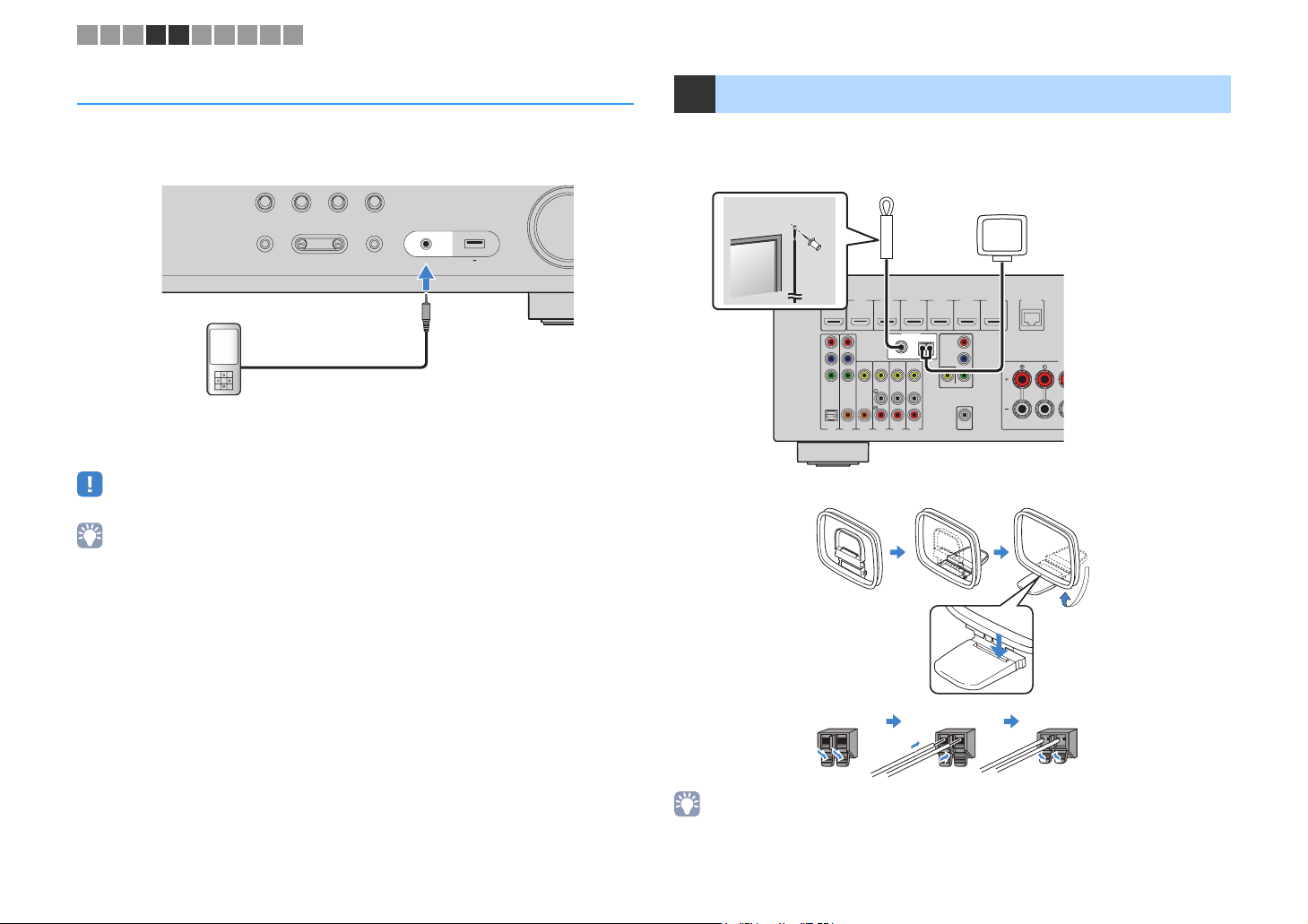
Connecting to the jack on the front panel
Use the AUX jack on the front panel to temporarily connect devices such as portable
audio players to the unit.
Before making a connection, stop playback on the device and turn down the volume on the unit.
NET
TVBD/DVD
TONE CONTROL
PROGRAM
The unit (front)
Portable audio player
If you select “AUX” as the input source by pressing INPUT, the audio played back on
the device will be output from the unit.
• You need to prepare the audio cable that matches the output jacks on your device.
• For details on how to connect an USB storage device, see “Connecting a USB storage device” (p.58).
RADIO
STRAIGHT
(CONNECT)
AUX
5V 1A
AUDIO
5 Connecting the FM/AM antennas
Connect the supplied FM/AM antennas to the unit.
Fix the end of the FM antenna to a wall, and place the AM antenna on a flat surface.
FM antenna
AM antenna
COMPONENT
VIDEO
P
R
P
B
MON
IT
OR
OUT
The unit (rear)
Assembling and connecting the AM antenna
Hold down Insert Release
• Unwind only the length of cable needed from the AM antenna unit.
• The wires of the AM antenna have no polarity.
En 23
Page 24
1 2 3 4 5 6 7 8 9 10
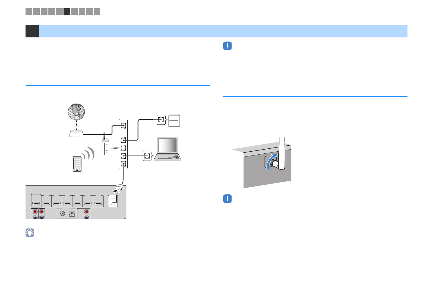
6 Preparing for connecting to a network
Connect the unit to a router (access point) with a network cable, or prepare the wireless
antenna for establishing a wireless network connection.
You can enjoy Internet radio or music files stored on media servers, such as PCs and
Network Attached Storage (NAS), on the unit.
Connecting a network cable
• Some security software installed on your PC or the firewall settings of network devices (such as a router)
may block the access of the unit to the network devices or the Internet. In these cases, configure the
security software or firewall settings appropriately.
• Each server must be connected to the same subnet as the unit.
• To use the service via the Internet, broadband connection is strongly recommended.
Connect the unit to your router with a commercially-available STP network cable (CAT-5
or higher straight cable).
Internet
WAN
LAN
Modem
Wireless
router
Network cable
N
HDMI6
HD
ETWORK
CP2.2
(NET)
P
HDMIOUT
R
HDMI4
HDMI3
HDMI2
HDMI1
(BD/DVD)
HDCP2.2
AR
C
ANTENNA
(RADI
O)
FM
75Ω
HDMI5
COMPONENT
AM
VIDEO
P
R
The unit (rear)
• If you are using a router that supports DHCP, you do not need to configure any network settings for the
unit, as the network parameters (such as the IP address) will be assigned automatically to it. You only need
to configure the network settings if your router does not support DHCP or if you want to configure the
network parameters manually (p.85).
• You can check whether the network parameters (such as IP address) are properly assigned to the unit in
“Information” (p.85) in the “Setup” menu.
Network Attached Storage
(NAS)
PC
Preparing a wireless antenna
If you connect the unit wirelessly, erect the wireless antenna.
For information on how to connect the unit to a wireless network, see “Connecting to a
network wirelessly” (p.31).
Erect the wireless antenna.
WIRELESS
• Do not apply excessive force on the wireless antenna. Doing so may damage the antenna.
En 24
Page 25

1 2 3 4 5 6 7 8 9 10
7 Connecting the power cable
After all the connections are complete, plug in the power cable.
The unit (rear)
SPEAKERS
CENT
ING
CABLAGECLASSE2
WSS
ER
SURROUND
To an AC wall outlet
En 25
Page 26
1 2 3 4 5 6 7 8 9 10
S
SS
ZQ
O
U
MUTE
M
E
U
NE
T
U
X
O
I
V
5
6
5
6
234
234
E
Y
Y
BLU
OW
G
S
P
SLEEP
LEE
HDMI
HDM
123 4
5 6
AV
A
123 4
56
BLUETOOTH
BLUETOOTH
BD
DVD
PROGRAM VOLUME
PROGRA
SETUP OPTION
RETURN
RED
HOME
HOM
STRAIGHT DIRECT ENHANCER BASS
TRAIGHIRECTENHANCERBA
RAV546
RAV546
ZQ56680
56680
FM AM
NET
USB
SCENE
SCENE
TV
NET
VOLUM
MUTE
TOP MENU
TOP MEN
TUNING PRESET
TUNING
ENTER
POP-UP/MENU
POP-UP/MEN
YELLOWGREEN
PRESE
AUXUSB
A
RADIO
PTION
DISPLA
DISPLAY
BLUE
MEMORY
MEMOR
zz
SETUP
Cursor keys
Cursor keys
ENTER
RETURN
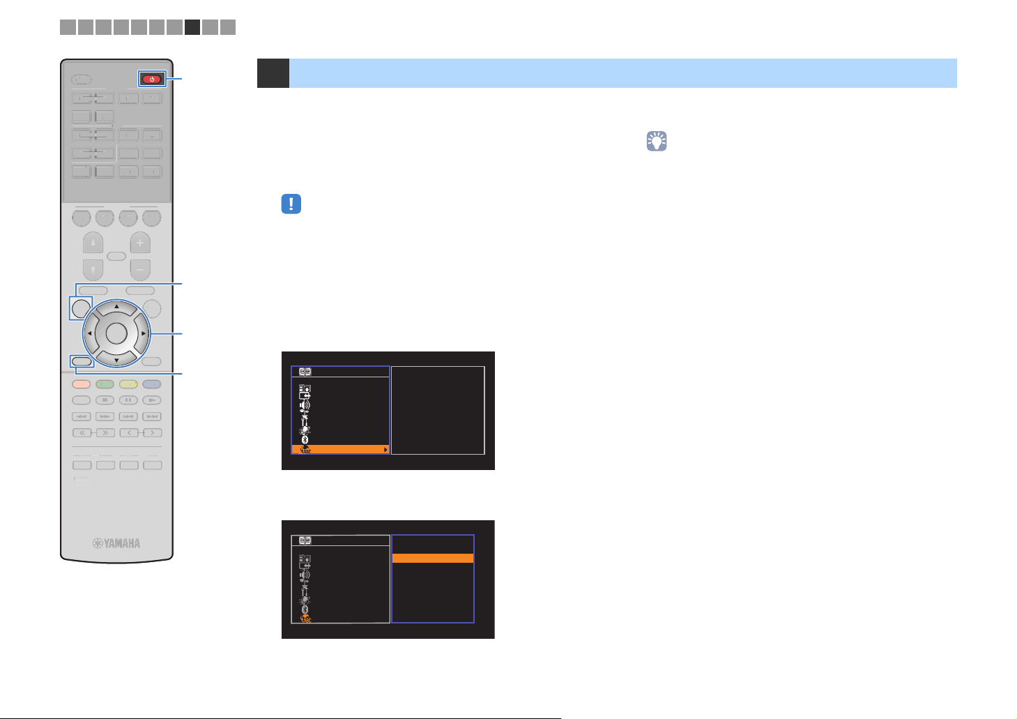
8 Selecting an on-screen menu language
Select the desired on-screen menu language.
Press z (receiver power) to turn on the unit.
1
Turn on the TV and switch the TV input to display
2
video from the unit (HDMI OUT jack).
• Operations with TV screen are available only when your TV is connected to
the unit via HDMI. If not, carry out operations while viewing the front display.
• If you turn on the unit for the first time, the message regarding the network
setup appears. To continue the language setup, press RETURN.
Press SETUP.
3
Use the cursor keys to select “Language” and press
4
ENTER.
Setup
Speaker
HDMI
Sound
ECO
Function
Network
Bluetooth
Language
Use the cursor keys to select the desired language.
5
English
日本語
Français
Deutsch
Español
Русский
Italiano
中文
To exit from the menu, press SETUP.
6
• The information on the front display is provided in English only.
Setup
Speaker
HDMI
Sound
ECO
Function
Network
Bluetooth
Language
English
日本語
Français
Deutsch
Español
Русский
Italiano
中文
En 26
Page 27
1 2 3 4 5 6 7 8 9 10
S
SS
ENTER
S
P
O
U
MUTE
M
E
U
NE
T
U
X
O
I
V
5
6
5
6
234
234
E
Y
Y
N
BLU
OW
G
S
P
SLEEP
LEE
HDMI
HDM
123 4
5 6
AV
A
123 4
56
BLUETOOTH
BLUETOOTH
BD
DVD
PROGRAM VOLUME
PROGRA
SETUP OPTION
ETU
RETURN
RETUR
RED
HOME
HOM
STRAIGHT DIRECT ENHANCER BASS
TRAIGHIRECTENHANCERBA
RAV546
RAV546
ZQ56680
ZQ56680
FM AM
NET
USB
SCENE
SCENE
TV
NET
VOLUM
MUTE
TOP MENU
TOP MEN
TUNING PRESET
TUNING
ENTER
POP-UP/MENU
POP-UP/MEN
YELLOWGREEN
PRESE
AUXUSB
A
RADIO
PTION
DISPLA
DISPLAY
BLUE
MEMORY
MEMOR
zz
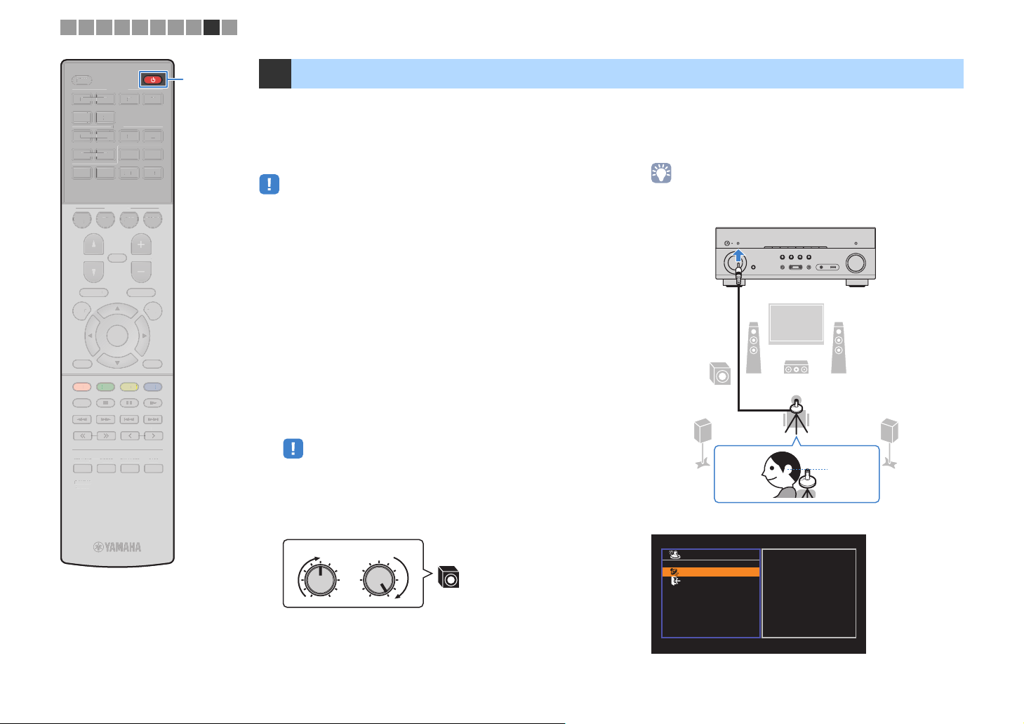
9 Optimizing the speaker settings automatically (YPAO)
The Yamaha Parametric room Acoustic Optimizer (YPAO) function
detects speaker connections, measures the distances from them to
your listening position(s), and then automatically optimizes the
speaker settings, such as volume balance and acoustic
Place the YPAO microphone at your listening
4
position and connect it to the YPAO MIC jack on the
front panel.
parameters, to suit your room.
• Place the YPAO microphone at your listening position (same height as your
• When you use the front 5.1-channel speaker (Virtual CINEMA FRONT)
configuration (p.13), set “Virtual CINEMA FRONT” (p.76) in the “Setup” menu to
“On” beforehand.
• Please note the following when using YPAO.
ears). We recommend the use of a tripod as a microphone stand. You can
use the tripod screws to stabilize the microphone.
The unit (front)
– Use YPAO after connecting a TV and speakers to the unit.
– During the measuring process, test tones are output at high volume. Ensure that
the test tones do not frighten small children.
– During the measuring process, you cannot adjust the volume.
– During the measuring process, keep the room as quiet as possible.
– Do not connect headphones.
– Do not stand between the speakers and the YPAO microphone during the
measurement process (about 3 minutes).
Press z (receiver power) to turn on the unit.
1
Turn on the TV and switch the TV input to display
2
45
12
9
3
video from the unit (HDMI OUT jack).
• Operations with TV screen are available only when your TV is connected to
the unit via HDMI. If not, carry out operations while viewing the front display.
Turn on the subwoofer and set the volume to half. If the
3
crossover frequency is adjustable, set it to maximum.
The following screen appears on the TV.
Ear height
VOLUME HIGH CUT
CROSSOVER/
MIN MAXMIN MAX
9
Auto Setup
Start
Exit
Press SETUP key
Start
to
En 27
Page 28
1 2 3 4 5 6 7 8 9 10
S
SS
6
O
U
MUTEPROGRAMVOLUMEPOP-UP/
U
U
U
SC
T
T
RADI
O
5
6
6
234
234
FM
AM
TU
G
E
Y
Y
U
OW
G
S
P
SLEEP
LEE
HDMI
HDM
123 4
5 6
AV
123 4
56
5
BLUETOOTH
BLUETOOTH
BD
BD
DVD
DVD
PROGRAM VOLUME
SETUP OPTION
RETURN
RED
HOME
HOM
STRAIGHT DIRECT ENHANCER BASS
TRAIGHTIRECTENHANCERBA
RAV546
RAV54
ZQ56680
ZQ56680
FM AM
NET
N
SB
SCENE
ENE
V
TV
NET
NE
MUTE
TOP MENU
TOP MEN
TUNING PRESET
POP-UP/MENU
ENTER
YELLOWGREEN
YEL
EEN
NIN
PRESE
AUXUSB
A
RADIO
MEN
PTION
DISPLA
DISPLAY
BLUE
BL
MEMORY
MEMOR
SETUP
Cursor keys
Cursor keys
ENTER
RETURN
To start the measurement, use the cursor keys to
5
select “Start” and press SETUP.
The measurement will start in 10 seconds. Press ENTER to
start the measurement immediately.
• To stop the measurement temporarily, press RETURN and follow the
procedure in “Error messages” (p.29).
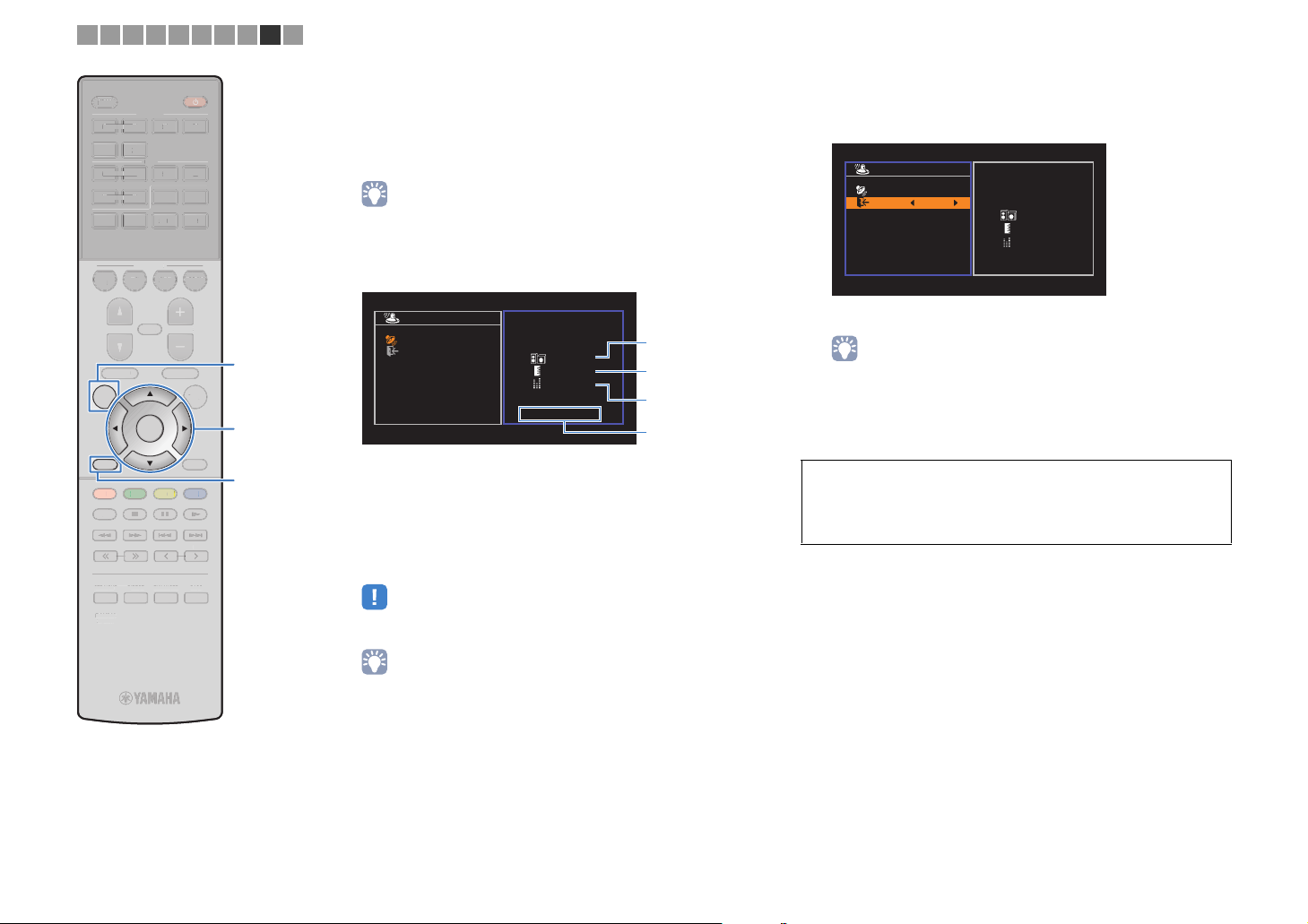
The following screen appears on the TV when the
measurement finishes.
Auto Setup
Start
Exit
Measurement
Finished
Result
3 / 2 / 0.1 ch
3.0 / 10.5 m
-3.0 / +10.0 dB
OK:ENTER
1
2
3
4
1 The number of speakers (front side/rear
side/subwoofer)
2 Speaker distance (nearest/farthest)
3 Adjustment range of speaker output level
4 Warning message (if available)
• If any error message (such as E-1) or warning message (such as W-1)
appears, see “Error messages” (p.29) or “Warning messages” (p.30).
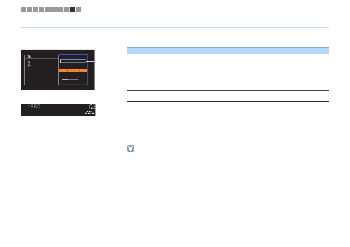
Use the cursor keys (e/r) to select “SAVE” and
6
press ENTER.
Auto Setup
Start
Exit
SAVE
Measurement
Finished
Result
3 / 2 / 0.1 ch
3.0 / 10.5 m
-3.0 / +10.0 dB
The adjusted speaker settings are applied.
• To finish the measurement without saving the result, select “CANCEL”.
Disconnect the YPAO microphone from the unit.
7
This completes optimization of the speaker settings.
Caution
• The YPAO microphone is sensitive to heat, so should not be placed anywhere
where it could be exposed to direct sunlight or high temperatures (such as on
top of AV equipment).
• A speaker with a problem is indicated by blinking of the speaker indicators in
the front display.
• If multiple warnings are given (when operating with the front display), use
the cursor keys (q/w) to check the other warning messages.
En 28
Page 29
1 2 3 4 5 6 7 8 9 10
Error messages
If any error message is displayed during the measurement, resolve the problem and perform YPAO again.
Error message Cause Remedy
Auto Setup
Start
Exit
ERROR
E-5:Noisy
PROCEED
5%
TV screen
CHARGE
OUT
ECO
ENHANCER
STEREO
TUNED
SLEEP
MUTE
VOL.
ADAPTIVE DRC
VIRTUAL
E-5:NOISY
Front display
■ Procedure to handle errors
Check the content of error message and
1
press ENTER.
Use the cursor keys (e/r) to select the
2
desired operation.
To exit the YPAO measurement:
a Select “EXIT” and press ENTER.
b Use the cursor keys (q/w) to select “Exit” and press
ENTER.
c Disconnect the YPAO microphone from the unit.
To retry the
beginning:
Select “RETRY” and press ENTER.
To proceed with the current YPAO
measurement (for E-5 and E-9 only):
Select “PROCEED” and press ENTER.
YPAO
measurement from
Error
message
E-1:No Front SP
(E-1:NO FRNT SP)
E-2:No Sur. SP
(E-2:NO SUR SP)
E-5:Noisy
(E-5:NOISY)
E-7:No MIC
(E-7:NO MIC)
E-8:No Signal
(E-8:NO SIGNAL)
E-9:User Cancel
(E-9:CANCEL)
E-10:Internal Err.
(E-10:INTERNAL)
• Texts in parentheses denote indicators on the front display.
Front speakers are not detected.
One of the surround speakers cannot be
detected.
The noise is too loud.
The YPAO microphone has been removed.
The YPAO microphone cannot detect test
tones.
The measurement has been canceled. Retry or exit YPAO as necessary.
An internal error has occurred.
Exit YPAO, turn off the unit, and then check the speaker
connections.
Keep the room quiet and retry YPAO. If you select
“PROCEED”, YPAO takes the measurement again and
ignores any noise detected.
Connect the YPAO microphone to the YPAO MIC jack firmly
and retry YPAO.
Connect the YPAO microphone to the YPAO MIC jack firmly
and retry YPAO. If this error occurs repeatedly, contact the
nearest authorized Yamaha dealer or service center.
Exit YPAO, and turn off and on the unit. If this error occurs
repeatedly, contact the nearest authorized Yamaha dealer or
service center.
En 29
Page 30
1 2 3 4 5 6 7 8 9 10
Warning messages
If a warning message is displayed after the measurement, you can still save the measurement results by following on-screen instructions.
However, we recommend you perform YPAO again in order to use the unit with the optimal speaker settings.
Warning message Cause Remedy
Auto Setup
Start
Exit
TV screen
CHARGE
OUT
ECO
W-1:PHASE
Front display
Measurement
Finished
Result
3 / 2 / 0.1 ch
3.0 / 10.5 m
-3.0 / +10.0 dB
OK:ENTER
W-1:Out of Phase
Problem speaker (blinks)
STEREO
TUNED
SLEEP
MUTE
VOL.
ADAPTIVE DRC
ENHANCER
VIRTUAL
Warning
message
W-1:Out of Phase
(W-1:PHASE)
W-2:Over Distance
(W-2:DISTANCE)
W-3:Level Error
(W-3:LEVEL)
A speaker cable may be connected with the
reverse polarity (+/-).
A speaker is placed more than 24 m (80 ft)
from the listening position.
There are significant volume differences
between the speakers.
Check the cable connections (+/-) of the problem speaker.
If the speaker is connected incorrectly:
Turn off the unit, reconnect the speaker cable.
If the speaker is connected correctly:
Depending on the type of speakers or room environment, this
message may appear even if the speakers are connected
correctly. In this case, you can ignore the message.
Exit YPAO, turn off the unit, and place the problem speaker
within 24 m (80 ft) of the listening position.
Check the usage environment and cable connections (+/-) of
each speaker, and the volume of the subwoofer. If there is
any problem, exit YPAO, turn off the unit, and then reconnect
speaker cable or correct the speaker positions. We
recommend using the same speakers or speakers with
specifications that are as similar as possible.
■ Procedure to handle warnings
Check the content of warning message
1
and press ENTER.
Use the cursor keys (e/r) to select the
2
desired operation.
To save the measurement results:
Select “SAVE” and press ENTER.
To discard the measurement result:
Select “CANCEL” and press ENTER.
Disconnect the YPAO microphone from
3
the unit.
• Texts in parentheses denote indicators on the front display.
En 30
Page 31

1 2 3 4 5 6 7 8 9 10
10 Connecting to a network wirelessly
Connect the unit to a wireless router (access point) or a mobile device by establishing a
wireless connection.
• When you connect the unit to a router with a network cable, you need not do this procedure.
Selecting the connection method
Select a connection method according to your network environment.
■ Connecting with a wireless router (access point)
Connect the unit to a wireless router (access point).
You can enjoy Internet radio, AirPlay, or music files stored on media servers (PC/NAS)
on the unit.
You can also use the application for smartphone / tablet “AV CONTROLLER” (p.6) to
control the unit from mobiles devices or enjoy music files stored on mobiles devices on
the unit.
Internet
Wireless router
Modem
■ Connecting without a wireless router (access point)
Connect a mobile device to the unit directly.
You can use the application for smartphone / tablet “AV CONTROLLER” (p.6) to control
the unit from mobiles devices or enjoy music files stored on mobiles devices on the unit.
Mobile device
(such as iPhone)
For details on connection, see “Connecting a mobile device to the unit directly
(Wireless Direct)” (p.39).
• You cannot use Wireless Direct simultaneously with the wired LAN connection (p.24) or the wireless LAN
connection (p.32).
• When Wireless Direct is enabled, the unit cannot connect to the Internet. Therefore, you cannot use any
kind of Internet service such as Internet radio.
• Also the mobile device cannot connect to the Internet, so we recommend you disconnect the mobile device
from the unit.
The unit
Mobile device
(such as iPhone)
The unit
For details on connection, see “Connecting the unit to a wireless network” (p.32).
• You cannot use the wireless LAN connection simultaneously with the wired LAN connection (p.24) or
Wireless Direct (p.39).
• If the unit and the wireless router (access point) are too far apart, the unit may not connect to a wireless
router (access point). In such case, place them close to each other.
En 31
Page 32
1 2 3 4 5 6 7 8 9 10
S
SS
O
U
MUTE
M
E
U
NE
T
U
X
O
I
V
5
6
5
6
234
234
E
Y
Y
N
BLU
OW
G
S
P
SLEEP
LEE
HDMI
HDM
123 4
5 6
AV
A
123 4
56
BLUETOOTH
BLUETOOTH
BD
DVD
PROGRAM VOLUME
PROGRA
SETUP OPTION
RETURN
RETUR
RED
HOME
HOM
STRAIGHT DIRECT ENHANCER BASS
TRAIGHIRECTENHANCERBA
RAV546
RAV546
ZQ56680
ZQ56680
FM AM
NET
USB
SCENE
SCENE
TV
NET
VOLUM
MUTE
TOP MENU
TOP MEN
TUNING PRESET
TUNING
ENTER
POP-UP/MENU
POP-UP/MEN
YELLOWGREEN
PRESE
AUXUSB
A
RADIO
PTION
DISPLA
DISPLAY
BLUE
MEMORY
MEMOR
zz
SETUP
Cursor keys
Cursor keys
ENTER
Connecting the unit to a wireless network
There are several methods to connect the unit to a wireless
network.
Select a connection method according to your environment.
Do you own iOS devices
(iPhone/iPod touch)?
No
Does your wireless router
(access point) has a WPS
button?
No
Yes
A (p.32)
Yes
B (p.34)
C (p.35)
■ A: Sharing the iOS device setting
You can easily setup a wireless connection by applying the
connection settings on iOS devices (iPhone/iPod touch).
Before proceeding, confirm that your iOS device is connected to a
wireless router.
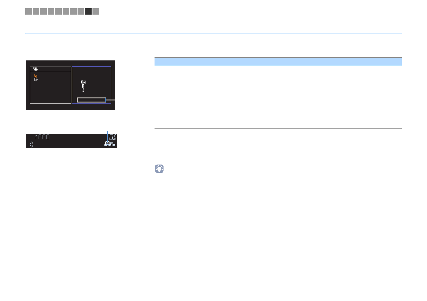
Press z (receiver power) to turn on the unit.
1
Turn on the TV and switch the TV input to display
2
video from the unit (HDMI OUT jack).
Use the cursor keys (e/r) to select “Wireless
6
(Wi-Fi)” and press ENTER.
Network Connection
Connection Wireless (Wi-Fi)
OK:ENTER
Back:RETURN
• The unit may connect automatically to the access point to which it has
connected previously. In this case, the message indicating the successful
connection will appear. You can ignore this message and proceed to the
next step.
Use the cursor keys (q/w) to select “Share Wi-Fi
7
Settings(iOS)” and press ENTER.
Wireless (Wi-Fi)
Select a setup method.
WPS Button
Share Wi-Fi Settings(iOS)
Access Point Scan
Manual Setting
PIN Code
OK:ENTER
Back:RETURN
• Operations with TV screen are available only when your TV is connected to
the unit via HDMI.
Press SETUP.
3
Use the cursor keys (q/w) to select “Network” and
4
press ENTER.
Use the cursor keys (q/w) to select “Network
5
Connection” and press ENTER.
En 32
Page 33

1 2 3 4 5 6 7 8 9 10
S
SS
S
P
O
U
MUTE
M
E
U
NE
T
U
X
O
I
V
5
6
5
6
234
234
E
Y
Y
N
BLU
OW
G
S
P
SLEEP
LEE
HDMI
HDM
123 4
5 6
AV
A
123 4
56
BLUETOOTH
BLUETOOTH
BD
DVD
PROGRAM VOLUME
PROGRA
SETUP OPTION
ETU
RETURN
RETUR
RED
HOME
HOM
STRAIGHT DIRECT ENHANCER BASS
TRAIGHIRECTENHANCERBA
RAV546
RAV546
ZQ56680
ZQ56680
FM AM
NET
USB
SCENE
SCENE
TV
NET
VOLUM
MUTE
TOP MENU
TOP MEN
TUNING PRESET
TUNING
ENTER
POP-UP/MENU
POP-UP/MEN
YELLOWGREEN
PRESE
AUXUSB
A
RADIO
PTION
DISPLA
DISPLAY
BLUE
MEMORY
MEMOR
Cursor keys
Cursor keys
ENTER
Use the cursor keys (q/w) and ENTER to select the
8
desired connection method.
Share Wi-Fi Settings
Select method for sharing
setting with iOS device.
Wireless (WAC)
USB Cable
OK:ENTER
Back:RETURN
The following connection methods are available.
You can apply the connection settings on the iOS
Wireless (WAC)
USB Cable
• When you use wired network connection, Wireless (WAC) is not available.
Read the on-screen description and press ENTER.
9
device to the unit using a wireless connection. For
details, see “Sharing the iOS device setting
wirelessly”.
(You need iOS device with iOS 7 or later.)
You can apply the connection settings on the iOS
device to the unit using a USB cable. For details,
see “Sharing the iOS device setting using a USB
cable”.
(You need iOS device with iOS 5 or later.)
❑ Sharing the iOS device setting wirelessly
If you select “Wireless (WAC)” as the connection method, perform
the network setting sharing operation on your iOS device. (The
following procedure is a setup example for iOS 8.)
On the iOS device, select the unit as the AirPlay
1
speaker in the Wi-Fi screen.
iOS (example of English version)
The name of the unit
Select the network (access point) of which you want
2
to share the settings with the unit.
iOS (example of English version)
Tap here to start setup
The network currently selected
When the sharing process finishes, the unit is automatically
connected to the selected network (access point).
En 33
Page 34

1 2 3 4 5 6 7 8 9 10
S
SS
O
U
MUTE
M
E
U
NE
T
U
X
O
I
V
5
6
5
6
234
234
E
Y
Y
N
BLU
OW
G
S
P
SLEEP
LEE
HDMI
HDM
123 4
5 6
AV
A
123 4
56
BLUETOOTH
BLUETOOTH
BD
DVD
PROGRAM VOLUME
PROGRA
SETUP OPTION
RETURN
RETUR
RED
HOME
HOM
STRAIGHT DIRECT ENHANCER BASS
TRAIGHIRECTENHANCERBA
RAV546
RAV546
ZQ56680
ZQ56680
FM AM
NET
USB
SCENE
SCENE
TV
NET
VOLUM
MUTE
TOP MENU
TOP MEN
TUNING PRESET
TUNING
ENTER
POP-UP/MENU
POP-UP/MEN
YELLOWGREEN
PRESE
AUXUSB
A
RADIO
PTION
DISPLA
DISPLAY
BLUE
MEMORY
MEMOR
zz
SETUP
ENTER
❑ Sharing the iOS device setting using a USB cable
If you select “USB Cable” as the connection method, follow the
procedure below to share the iOS device setting with the unit.
Connect the iOS device to the USB jack, and disable
1
the screen lock on the iOS device.
The unit (front)
AUX
5V 1A
AUDIO
Press ENTER on the remote control.
2
Tap “Allow” in the message appeared on the iOS
3
device.
When the connection process finishes, “Completed”
appears on the TV screen.
To exit from the menu, press SETUP.
4
■ B: Using the WPS button configuration
You can easily set up a wireless connection with one push of the
WPS button.
Press z (receiver power) to turn on the unit.
1
Hold down INFO (WPS) on the front panel for 3
2
seconds.
“Press WPS button on Access Point” appears on the front
display.
Push the WPS button on the wireless router (access
3
point).
When the connection process finishes, “Completed”
appears on the front display.
If “Not connected” appears, repeat from step 1 or try
another connection method.
• Depending on the model of the wireless router (access point), the unit may not
connect to it. In this case, try connection with “Access Point Scan” or “Manual
Setting” (p.35).
• You can use “WPS Button” (p.35) in the “Setup” menu to set up a wireless
connection with the WPS button.
About WPS
WPS (Wi-Fi Protected Setup) is a standard established by the
Wi-Fi Alliance, which allows easy establishment of a wireless
home network.
En 34
Page 35

1 2 3 4 5 6 7 8 9 10
S
SS
O
U
MUTE
M
E
U
NE
T
U
X
O
I
V
5
6
5
6
234
234
E
Y
Y
N
BLU
OW
G
S
P
SLEEP
LEE
HDMI
HDM
123 4
5 6
AV
A
123 4
56
BLUETOOTH
BLUETOOTH
BD
DVD
PROGRAM VOLUME
PROGRA
SETUP OPTION
RETURN
RETUR
RED
HOME
HOM
STRAIGHT DIRECT ENHANCER BASS
TRAIGHIRECTENHANCERBA
RAV546
RAV546
ZQ56680
ZQ56680
FM AM
NET
USB
SCENE
SCENE
TV
NET
VOLUM
MUTE
TOP MENU
TOP MEN
TUNING PRESET
TUNING
ENTER
POP-UP/MENU
POP-UP/MEN
YELLOWGREEN
PRESE
AUXUSB
A
RADIO
PTION
DISPLA
DISPLAY
BLUE
MEMORY
MEMOR
zz
SETUP
Cursor keys
Cursor keys
ENTER
■ C: Using other connection methods
If your wireless router (access point) does not support WPS button
configuration method, follow the procedure below to configure the
wireless network settings.
Press z (receiver power) to turn on the unit.
1
Turn on the TV and switch the TV input to display
2
video from the unit (HDMI OUT jack).
• Operations with TV screen are available only when your TV is connected to
the unit via HDMI.
Press SETUP.
3
Use the cursor keys (q/w) to select “Network” and
4
press ENTER.
Use the cursor keys (q/w) to select “Network
5
Connection” and press ENTER.
Use the cursor keys (e/r) to select “Wireless
6
(Wi-Fi)” and press ENTER.
Network Connection
Connection Wireless (Wi-Fi)
OK:ENTER
Back:RETURN
Use the cursor keys (q/w) to select the desired
7
connection method and press ENTER.
Wireless (Wi-Fi)
Select a setup method.
WPS Button
Share Wi-Fi Settings(iOS)
Access Point Scan
Manual Setting
PIN Code
OK:ENTER
Back:RETURN
The following connection methods are available.
WPS Button
Share Wi-Fi
Settings(iOS)
Access Point
Scan
Manual Setting
PIN Code
You can set up a wireless connection with the
WPS button while viewing the TV screen. Follow
the instructions displayed on the TV screen.
See “Sharing the iOS device setting” (p.32).
You can set up a wireless connection by
searching for an access point. For details on
settings, see “Searching for an access point”
(p.36).
You can setup a wireless connection by entering
the required information (such as SSID)
manually. For details on settings, see “Setting up
the wireless connection manually” (p.37).
You can set up a wireless connection by entering
the unit’s PIN code into the wireless router
(access point). The method is available if the
wireless router (access point) supports the WPS
PIN code method. For details on settings, see
“Using the WPS PIN code” (p.38).
• The unit may connect automatically to the access point to which it has
connected previously. In this case, the message indicating the successful
connection will appear. You can ignore this message and proceed to the
next step.
En 35
Page 36

1 2 3 4 5 6 7 8 9 10
S
SS
ZQ
O
U
MUTE
M
E
U
NE
T
U
X
O
I
V
5
6
5
6
234
234
E
Y
Y
N
BLU
OW
G
S
P
SLEEP
LEE
HDMI
HDM
123 4
5 6
AV
A
123 4
56
BLUETOOTH
BLUETOOTH
BD
DVD
PROGRAM VOLUME
PROGRA
SETUP OPTION
RETURN
RETUR
RED
HOME
HOM
STRAIGHT DIRECT ENHANCER BASS
TRAIGHIRECTENHANCERBA
RAV546
RAV546
ZQ56680
56680
FM AM
NET
USB
SCENE
SCENE
TV
NET
VOLUM
MUTE
TOP MENU
TOP MEN
TUNING PRESET
TUNING
ENTER
POP-UP/MENU
POP-UP/MEN
YELLOWGREEN
PRESE
AUXUSB
A
RADIO
PTION
DISPLA
DISPLAY
BLUE
MEMORY
MEMOR
SETUP
Cursor keys
Cursor keys
ENTER
❑ Searching for an access point
If you select “Access Point Scan” as the connection method, the
unit starts searching for access points. After a while, the list of
available access points appears on the TV screen.
Use the cursor keys (q/w) to select the desired
1
access point and press ENTER.
The wireless connection setting screen appears on the TV.
Access Point Scan
SSID:
Security:
Security Key:
Press ENTER.
2
Use the cursor keys and ENTER to enter the
3
security key.
Network Connection
abc_
( ) [ ] { } < > * ! ? # % &
. , : ; _ | / \ $ ~^´ ’ `
0 1 2 3 4 5 6 7 8 9 + - =
← Aa BKSP Space DEL →
a b c d e f g h i j k l m
n o p q r s t u v w x y z
OK
CANCEL
CLEAR
Connect
Access Point X
WPA-PSK (AES)
CANCEL:
ENTEREdit:
RETURN
Use the cursor keys (q/w) to select “Connect” and
4
press ENTER to start the connection process.
When the connection process finishes, “Completed”
appears on the TV screen.
If “Not connected” appears, repeat from step 1 or try
another connection method.
To exit from the menu, press SETUP.
5
Button functions
[←]/[→]: Moves the cursor left and right.
[Aa]: Switches the letter cases (upper/lower).
[BKSP]: Deletes the character to the left of the selected one.
[Space]: Enters a space.
[DEL]: Deletes the selected character.
When finished entering the key, select “OK” to return to the
previous screen.
En 36
Page 37

1 2 3 4 5 6 7 8 9 10
S
SS
ZQ
O
U
MUTE
M
E
U
NE
T
U
X
O
I
V
5
6
5
6
234
234
E
Y
Y
N
BLU
OW
G
S
P
SLEEP
LEE
HDMI
HDM
123 4
5 6
AV
A
123 4
56
BLUETOOTH
BLUETOOTH
BD
DVD
PROGRAM VOLUME
PROGRA
SETUP OPTION
RETURN
RETUR
RED
HOME
HOM
STRAIGHT DIRECT ENHANCER BASS
TRAIGHIRECTENHANCERBA
RAV546
RAV546
ZQ56680
56680
FM AM
NET
USB
SCENE
SCENE
TV
NET
VOLUM
MUTE
TOP MENU
TOP MEN
TUNING PRESET
TUNING
ENTER
POP-UP/MENU
POP-UP/MEN
YELLOWGREEN
PRESE
AUXUSB
A
RADIO
PTION
DISPLA
DISPLAY
BLUE
MEMORY
MEMOR
SETUP
Cursor keys
Cursor keys
ENTER
❑ Setting up the wireless connection manually
If you select “Manual Setting” as the connection method, the
wireless connection setting screen appears on the TV.
You need to setup the SSID (network name), encryption method
and security key for your network.
Manual Setting
SSID:
Security:
Security Key:
Use the cursor keys (q/w) to select “SSID” and
1
press ENTER.
Use the cursor keys and ENTER to enter the SSID of
2
the access point.
Network Connection
****
( ) [ ] { } < > * ! ? # % &
. , : ; _ | / \ $ ~^´ ’ `
0 1 2 3 4 5 6 7 8 9 + - =
← Aa BKSP Space DEL →
a b c d e f g h i j k l m
n o p q r s t u v w x y z
OK
CANCEL
CLEAR
When finished entering the key, select “OK” to return to the
previous screen.
Use the cursor keys (q/w) to select “Security” and
3
the cursor keys (e/r) to select the encryption
method.
Choices
None, WEP, WPA-PSK (AES), Mixed Mode
Connect
Access Point X
CANCEL:
ENTEREdit:
RETURN
None
• If you select “None”, the connection may be insecure since the
communication is not encrypted.
Use the cursor keys (q/w) to select “Security Key”
4
and press ENTER.
• If you select “None” in step 3, this item is not available.
Use the cursor keys and ENTER to enter the
5
security key.
If you select “WEP” in step 3, enter either 5 or 13 character
string, or 10 or 26 hexadecimal digits.
If you select the method other than “WEP” in step 3, enter
either 8 to 63 character string, or 64 hexadecimal digits.
Network Connection
****
( ) [ ] { } < > * ! ? # % &
. , : ; _ | / \ $ ~^´ ’ `
0 1 2 3 4 5 6 7 8 9 + - =
← Aa BKSP Space DEL →
a b c d e f g h i j k l m
n o p q r s t u v w x y z
OK
CANCEL
CLEAR
When finished entering the key, select “OK” to return to the
previous screen.
Use the cursor keys (q/w) to select “Connect” and
6
press ENTER to start the connection process.
When the connection process finishes, “Completed”
appears on the TV screen.
If “Not connected” appears, check that all the information is
entered correctly, and repeat from step 1.
To exit from the menu, press SETUP.
7
En 37
Page 38

1 2 3 4 5 6 7 8 9 10
S
SS
ZQ
O
U
MUTE
M
E
U
NE
T
U
X
O
I
V
5
6
5
6
234
234
E
Y
Y
N
BLU
OW
G
S
P
SLEEP
LEE
HDMI
HDM
123 4
5 6
AV
A
123 4
56
BLUETOOTH
BLUETOOTH
BD
DVD
PROGRAM VOLUME
PROGRA
SETUP OPTION
RETURN
RETUR
RED
HOME
HOM
STRAIGHT DIRECT ENHANCER BASS
TRAIGHIRECTENHANCERBA
RAV546
RAV546
ZQ56680
56680
FM AM
NET
USB
SCENE
SCENE
TV
NET
VOLUM
MUTE
TOP MENU
TOP MEN
TUNING PRESET
TUNING
ENTER
POP-UP/MENU
POP-UP/MEN
YELLOWGREEN
PRESE
AUXUSB
A
RADIO
PTION
DISPLA
DISPLAY
BLUE
MEMORY
MEMOR
SETUP
Cursor keys
Cursor keys
ENTER
❑ Using the WPS PIN code
If you select “PIN Code” as the connection method, the list of
available access points appears on the TV screen.
Use the cursor keys (q/w) to select the desired
1
access point and press ENTER.
The PIN code of the unit appears on the TV screen.
PIN Code
PIN Code
: 00000000
Enter the PIN code
into the access point.
OK:ENTER
Back:RETURN
Enter the unit’s PIN code into the wireless router
2
(access point).
For details on settings, refer to the instruction manual of the
wireless router (access point).
Press ENTER to start the connection process.
3
When the connection process finishes, “Completed”
appears on the TV screen.
If “Not connected” appears, repeat from step 1 or try
another connection method.
To exit from the menu, press SETUP.
4
En 38
Page 39
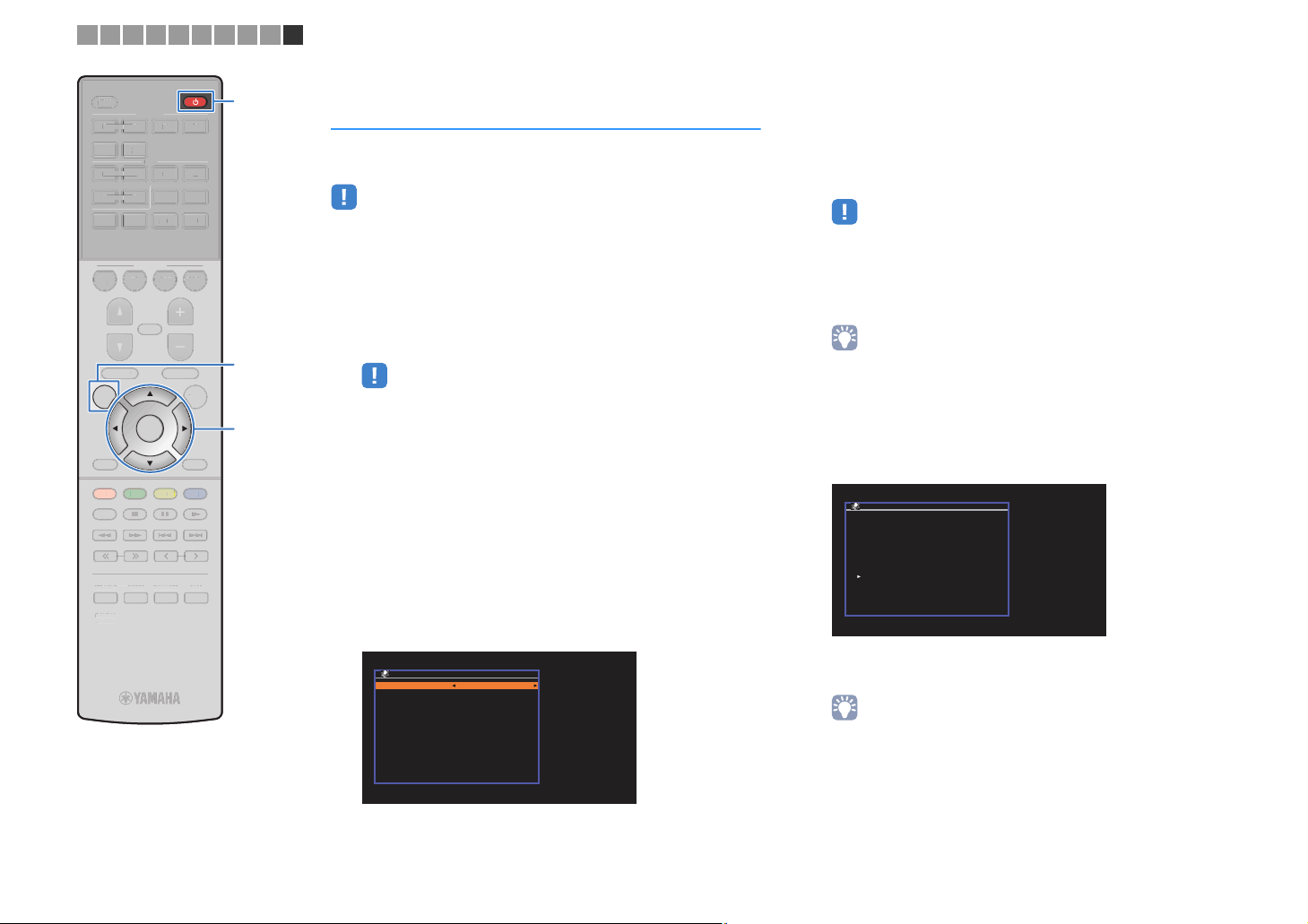
1 2 3 4 5 6 7 8 9 10
S
SS
O
U
MUTE
M
E
U
NE
T
U
X
O
I
V
5
6
5
6
234
234
E
Y
Y
N
BLU
OW
G
S
P
SLEEP
LEE
HDMI
HDM
123 4
5 6
AV
A
123 4
56
BLUETOOTH
BLUETOOTH
BD
DVD
PROGRAM VOLUME
PROGRA
SETUP OPTION
RETURN
RETUR
RED
HOME
HOM
STRAIGHT DIRECT ENHANCER BASS
TRAIGHIRECTENHANCERBA
RAV546
RAV546
ZQ56680
ZQ56680
FM AM
NET
USB
SCENE
SCENE
TV
NET
VOLUM
MUTE
TOP MENU
TOP MEN
TUNING PRESET
TUNING
ENTER
POP-UP/MENU
POP-UP/MEN
YELLOWGREEN
PRESE
AUXUSB
A
RADIO
PTION
DISPLA
DISPLAY
BLUE
MEMORY
MEMOR
zz
SETUP
Cursor keys
Cursor keys
ENTER
Connecting a mobile device to the unit
directly (
Follow the procedure below to connect a mobile device to the unit
directly.
• Wireless Direct connection may be insecure since the communication is not
strongly encrypted. The unit may operate by playback operation on wireless
devices connected to the unit without permission.
Press z (receiver power) to turn on the unit.
1
Turn on the TV and switch the TV input to display
2
video from the unit (HDMI OUT jack).
• Operations with TV screen are available only when your TV is connected to
Press SETUP.
3
Use the cursor keys (q/w) to select “Network” and
4
press ENTER.
Use the cursor keys (q/w) to select “Network
5
Connection” and press ENTER.
Use the cursor keys (e/r) to select “Wireless
6
Direct” and press ENTER.
Wireless Direct
the unit via HDMI.
Network Connection
Connection Wireless Direct
)
Use the cursor keys (q/w) to select “Security” and
7
the cursor keys (e/r) to select the encryption
method.
Choices
None, WPA2-PSK (AES)
• If you select “None”, the connection may be insecure since the
communication is not encrypted.
Use the cursor keys (q/w) to select “Security Key”
8
and press ENTER.
• If you select “None” in step 7, this item is not available.
Use the cursor keys and ENTER to enter the
9
security key.
Enter either 8 to 63 character string, or 64 hexadecimal
digits.
Network Connection
abc_
( ) [ ] { } < > * ! ? # % &
. , : ; _ | / \ $ ~^´ ’ `
0 1 2 3 4 5 6 7 8 9 + - =
← Aa BKSP Space DEL →
a b c d e f g h i j k l m
n o p q r s t u v w x y z
OK
CANCEL
CLEAR
When finished entering the key, select “OK” to return to the
previous screen.
• Before proceeding to the next step, record the following information. These
information will be needed to configure the Wi-Fi setting of a mobile device.
OK:ENTER
Back:RETURN
– SSID displayed on the TV screen
– Security key you have just entered
En 39
Page 40

1 2 3 4 5 6 7 8 9 10
S
SS
ZQ
O
U
MUTE
M
E
U
NE
T
U
X
O
I
V
5
6
5
6
234
234
E
Y
Y
N
BLU
OW
G
S
P
SLEEP
LEE
HDMI
HDM
123 4
5 6
AV
A
123 4
56
BLUETOOTH
BLUETOOTH
BD
DVD
PROGRAM VOLUME
PROGRA
SETUP OPTION
RETURN
RETUR
RED
HOME
HOM
STRAIGHT DIRECT ENHANCER BASS
TRAIGHIRECTENHANCERBA
RAV546
RAV546
ZQ56680
56680
FM AM
NET
USB
SCENE
SCENE
TV
NET
VOLUM
MUTE
TOP MENU
TOP MEN
TUNING PRESET
TUNING
ENTER
POP-UP/MENU
POP-UP/MEN
YELLOWGREEN
PRESE
AUXUSB
A
RADIO
PTION
DISPLA
DISPLAY
BLUE
MEMORY
MEMOR
SETUP
Cursor keys
Cursor keys
ENTER
Use the cursor keys (q/w) to select “Save” and
10
press ENTER to save the setting.
This completes the settings and “Completed” appears on
the TV screen.
Next, configure the Wi-Fi settings of a mobile device.
Configure the Wi-Fi settings of a mobile device.
11
For details on settings of your mobile device, refer to the
instruction manual of the mobile device.
a Enable the Wi-Fi function on the mobile device.
b Select the SSID displayed in step 9 from the list of available
access points.
c When you are prompted for a password, enter the security key
displayed in step 9.
To exit from the menu, press SETUP.
12
En 40
Page 41

SLEEP
S
D
IRECT
SS
6
SETUPO
UPROGRAM
U
SC
T
O
HDMI
AV
5
6
6
234
3
TU
G
T
E
Y
Y
N
U
E
L
OW
G
R
RE
D
S
P
LEE
HDMI
123 4
5 6
AV
123 4
56
5
BLUETOOTH
FM AM
NET
AUXUSB
Input selection
Input selection
keys
keys
PLAYBACK
Basic playback procedure
Turn on the external devices (such as a TV or
1
BD/DVD player) connected to the unit.
SCENE
ENE
BD
BD
TV
TV
NET
NE
RADIO
MUTE
ENTER
EEN
POP-UP/MENU
POP-UP/MEN
YELLOWGREEN
YEL
PRESE
ENHANCERBA
RAD
PTION
DISPLA
DISPLAY
BLUE
BL
MEMORY
MEMOR
D
D
DVD
PROGRAM VOLUME
TOP MENU
TOP MEN
SETUP OPTION
RETURN
RETUR
RED
HOME
HOM
TUNING PRESET
NIN
STRAIGHT DIRECT ENHANCER BASS
TRAIGHT
RAV546
RAV54
ZQ56680
ZQ56680
VOLUME
MUTE
Use the input selection keys to select an input
2
source.
Start playback on the external device or select a
3
radio station.
Refer to the instruction manual for the external device.
For details on the following operations, see the
corresponding pages.
• Listening to FM/AM radio (p.48)
• Playing back iPod music (p.53)
• Playing back music via BLUETOOTH (p.52)
• Playing back music stored on a USB storage device
(p.58)
• Playing back music stored on media servers (PCs/NAS)
(p.61)
• Listening to Internet radio (p.64)
• Playing back music with AirPlay (p.56)
Press VOLUME to adjust the volume.
4
• To mute the audio output, press MUTE. Press MUTE again to unmute.
• To adjust the treble/bass settings, use the “Option” menu or TONE
CONTROL on the front panel (p.70).
En 41
Page 42

SLEEP
S
SS
RAV546
SETUPO
TO
U
U
NE
T
U
X
HDMI
AV
5
6
234
3
G
E
Y
Y
N
BLU
E
YELL
OW
G
RE
D
S
P
LEE
HDMI
123 4
5 6
AV
123 4
56
5 6
BLUETOOTH
BLUETOOTH
BD
DVD
PROGRAM VOLUME
PROGRAM
SETUP OPTION
RETURN
RETUR
RED
HOME
HOM
STRAIGHT DIRECT ENHANCER BASS
TRAIGHTDIRECTENHANCERBA
RAV546
ZQ56680
ZQ56680
FM AM
NET
USB
SCENE
TV
NET
VOLUME
MUTE
MUTE
TOP MENU
TUNING PRESET
TUNIN
P MEN
REEN
ENTER
POP-UP/MENU
POP-UP/MEN
YELLOWGREEN
PRESET
AUXUSB
A
RADIO
PTION
DISPLA
DISPLAY
BLUE
MEMORY
MEMOR
SCENE
Selecting the input source and favorite settings with one touch (SCENE)
The SCENE function allows you to select the assigned input source,
sound program, and Compressed Music Enhancer on/off with just
one touch.
Selecting a registered scene
Press SCENE.
1
The input source and settings registered to the
corresponding scene are selected. The unit turns on
automatically when it is in standby mode.
By default, the following settings are registered for each scene.
SCENE
Input HDMI 1 AV 1 NET RADIO TUNER
Sound program Sci-Fi STRAIGHT 5ch Stereo 5ch Stereo
Compressed
Music Enhancer
SCENE link
playback
• The SCENE link playback function allows you to automatically turn on the TV or
start playback of an external device connected to the unit via HDMI, in conjunction
with a scene selection. To enable SCENE link playback, set “SCENE” (p.79) in the
“Setup” menu to “On”.
OffOnOnOn
On On Off Off
Configuring scene assignments
Perform the following operations to prepare the
1
settings you want to assign to a scene.
• Select an input source (p.41)
• Select a sound program (p.43)
• Enable/disable Compressed Music Enhancer (p.47)
Hold down the desired SCENE key until “SET
2
Complete” appears on the front display.
CHARGE
OUT
ECO
ENHANCER
STEREO
TUNED
SLEEP
MUTE
VOL.
ADAPTIVE DRC
VIRTUAL
SET Complete
En 42
Page 43

SLEEP
6
SETU
P
U
MUTEVOLUME
U
U
US
SC
O
5
6
6
3
234
FM
AM
G
E
Y
Y
N
U
OW
G
P
SLEE
HDMI
HDM
123 4
1
5 6
AV
A
123 4
56
5
BLUETOOTH
BLUETOOTH
BD
B
DVD
DVD
PROGRAM VOLUME
SETUP OPTION
RETURN
RETUR
RED
HOME
HOM
STRAIGHT DIRECT ENHANCER BASS
RAV546
RAV54
ZQ56680
ZQ56680
FM AM
NET
B
SCENE
ENE
TV
TV
NET
NE
MUTE
TOP MENU
TOP MEN
TUNING PRESET
TUNIN
POP-UP/MENU
POP-UP/MEN
ENTER
ENTER
YELLOWGREEN
YEL
EEN
PRESE
AUXUSB
A
RADIO
RAD
DISPLA
DISPLAY
BLUE
BL
MEMORY
MEMOR
PROGRAM
OPTION
STRAIGHT
DIRECT
ENHANCER
BASS
Selecting the sound mode
The unit is equipped with a variety of sound programs and
surround decoders that allow you to enjoy playback sources with
your favorite sound mode (such as sound field effect or stereo
playback).
❑ I want to enjoy viewing video sources such as
movies, TV programs, or games.
• Select a sound program suitable for each video source by
pressing PROGRAM repeatedly (p.44).
❑ I want to enjoy listening to music sources or stereo
playback.
• Select a sound program suitable for music or stereo playback by
pressing PROGRAM repeatedly (p.45).
❑ I want to enjoy multichannel playback from
2-channel sources.
• Select a surround decoder in the “Option” menu (p.69).
❑ I want to enjoy unprocessed sounds in original
channels.
• Switch to the straight decode mode by pressing STRAIGHT
(p.46).
❑ I want to enjoy pure high fidelity sounds.
• Enable the direct playback mode by pressing DIRECT (p.47).
This mode reduces the electrical noise from other circuitry to allow
you to enjoy Hi-Fi sound quality.
❑ I want to enjoy listening to compressed music.
• Enable Compressed Music Enhancer by pressing ENHANCER
(p.47).
This mode lets you enjoy compressed music stored on a
BLUETOOTH device or USB storage device with additional depth
and breadth (p.47).
• The sound mode can be applied separately to each input source.
• When you play back audio signals with a sampling rate of higher than 96 kHz, the
straight decode mode (p.46) is automatically selected.
• You can check which speakers are currently outputting sound by looking at the
speaker indicators on the unit’s front panel (p.8).
❑ I want to enjoy enhanced bass sounds.
• Enable Extra Bass by pressing BASS (p.47).
En 43
Page 44

Enjoying stereoscopic sound fields (
CINEMA DSP 3D
)
The unit is equipped with a variety of sound programs that utilize Yamaha's original
DSP technology (CINEMA DSP 3D). It allows you to easily create sound fields like
actual movie theaters or concert halls in your room and enjoy natural stereoscopic
sound fields.
Sound program category
“CINEMA DSP” lights up
CHARGE
OUT
ECO
ENHANCER
STEREO
TUNED
SLEEP
MUTE
VOL.
ADAPTIVE DRC
VIRTUAL
Sci-Fi
Sound program
• You can adjust the sound field effect level in “DSP Level” (p.70) in the “Option” menu.
• To use the conventional CINEMA DSP, set “CINEMA DSP 3D Mode” (p.80) in the “Setup” menu to “Off”.
■ Sound programs suitable for movies (MOVIE)
The following sound programs are optimized for viewing video sources, such as
movies, TV programs, and games.
This program creates a sound field that emphasizes the surround feeling
Standard
Spectacle
Sci-Fi
Adventure
without disturbing the original acoustic positioning of multichannel audio,
such as Dolby Digital and DTS. Its design is based on the concept of the
ideal movie theater, in which the audience is surrounded by beautiful
reverberations from the left, right, and rear.
This program delivers the scale and grandeur of spectacular movie
productions. It delivers an expansive sound space to match the
cinemascope wide-screen, and boasts a broad dynamic range, providing
everything from small delicate sounds to powerful loud booms.
This program clearly reproduces the finely elaborated sound design of the
latest Sci-Fi and SFX movies. You can enjoy a variety of
cinematographically created virtual spaces reproduced with clear
separation between dialogue, sound effects, and background music.
This program is ideal for reproducing the sound design of action and
adventure movies precisely. The sound field restrains reverberations, but
puts emphasis on reproducing a sensation of expansiveness on both sides,
powerful space expanded widely to the left and right. The restrained depth
creates a clear and powerful space, while also maintaining the articulation
of the sounds and the separation of the channels.
Drama
Mono Movie
Sports
Action Game
Roleplaying Game
This program features stable reverberations that match a wide range of
movie genres, from serious dramas to musicals and comedies. The
reverberations are modest, but suitably stereophonic. The sound effects
and background music are reproduced with a gentle echo that does not
impinge on the articulation of the dialogue. You’ll never get tired listening for
long periods.
This program reproduces monaural video sources, such as classic movies,
in an atmosphere of a good old movie theater. The program creates a
pleasant space with depth, by adding breadth and the appropriate
reverberation to the original audio.
This program allows listeners to enjoy the rich vividness of sport broadcasts
and light entertainment programs. In sports broadcasts, the commentators’
voices are positioned clearly at the center, while the atmosphere inside the
stadium is realistically conveyed by the peripheral delivery of the sounds of
the fans in a suitable space.
This program is suitable for action games, such as car racing and fighting
games. The reality of, and emphasis on, various effects makes the player
feel like they are right in the middle of the action, allowing for greater
concentration. Use this program in combination with Compressed Music
Enhancer for a more dynamic and strong sound field.
This program is suitable for role-playing and adventure games. This
program adds depth to the sound field for natural and realistic reproduction
of background music, special effects, and dialogue from a wide variety of
scenes. Use this program in combination with Compressed Music
Enhancer for a clearer and more spatial sound field.
En 44
Page 45

■ Sound programs suitable for music (MUSIC)
The following sound programs are optimized for listening to music sources.
This program simulates a Munich concert hall with approximately 2,500
Hall in Munich
Hall in Vienna
Chamber
Cellar Club
The Roxy Theatre
The Bottom Line
Music Video
seats that uses stylish wood for the interior finishing. Fine, beautiful
reverberations spread richly, creating a calming atmosphere. The listener’s
virtual seat is at the center left of the arena.
This program simulates a 1700-seat, middle-sized concert hall with a
shoebox shape that is traditional in Vienna. Pillars and ornate carvings
create extremely complex reverberations from all around the audience,
producing a very full, rich sound.
This program creates a relatively wide space with a high ceiling, like an
audience hall in a palace. It offers pleasant reverberations that are suitable
for courtly music and chamber music.
This program simulates an intimate concert venue with a low ceiling and
homey atmosphere. A realistic, live sound field delivers powerful sounds
that make you feel as if you are sitting in the front row in front of a small
stage.
This program creates the sound field of a 460-seat rock music concert
venue in Los Angeles. The listener’s virtual seat is at the center left of the
hall.
This program creates the sound field at stage front in The Bottom Line, a
famous New York jazz club once. The floor can seat 300 people to the left
and right in a sound field offering real and vibrant sound.
This program allows you to enjoy videos of pop, rock, and jazz concerts, as
if you were there yourself. Immerse yourself in the hot concert atmosphere
thanks to the vividness of the singers and solos on stage, a presence
sound field that emphasizes the beat of rhythm instruments, and a surround
sound field that reproduces the space of a big live hall.
■ Sound programs suitable for stereo playback (STEREO)
You can select stereo playback.
■ Enjoying sound field effects without surround speakers
(Virtual CINEMA DSP)
If you select one of the sound programs (except 2ch Stereo and 5ch Stereo) when no
surround speakers are connected, the unit automatically creates the surround sound
field using the front-side speakers.
■ Enjoying surround sound with 5 speakers placed in
front (Virtual CINEMA FRONT)
You can enjoy the surround sound even when the surround speakers are placed in
front.
■ Enjoying surround sound with headphones
(SILENT CINEMA)
You can enjoy surround or sound field effects, like a multichannel speaker system, with
stereo headphones by connecting the headphones to the PHONES jack and selecting
a sound program or a surround decoder.
2ch Stereo
5ch Stereo
• CINEMA DSP 3D (p.44) and Virtual CINEMA DSP (p.45) do not work when “2ch Stereo” or “5ch Stereo” is
selected.
Use this program to mix down multichannel sources to 2 channels. When
multichannel signals are input, they are down mixed to 2 channels and
output from the front speakers (this program does not utilize CINEMA DSP).
Use this program to output sound from all speakers. When you play back
multichannel sources, the unit mixes down the source to 2 channels, and
then outputs the sound from all speakers. This program creates a larger
sound field and is ideal for background music at parties.
En 45
Page 46

SLEEP
SS
6
SETUPO
U
MUTEVOLUME
U
U
US
SC
O
5
6
6
3
234
FM
AM
G
SE
E
Y
Y
N
U
OW
G
P
SLEE
HDMI
HDMI
123 4
1
5 6
AV
A
123 4
56
5
BLUETOOTH
BLUETOOTH
BD
B
DVD
DVD
PROGRAM VOLUME
SETUP OPTION
RETURN
RETUR
RED
HOME
HOM
STRAIGHT DIRECT ENHANCER BASS
RAV546
RAV54
ZQ56680
ZQ56680
FM AM
NET
B
SCENE
ENE
TV
TV
NET
NE
MUTE
TOP MENU
TOP MEN
TUNING PRESET
TUNIN
POP-UP/MENU
POP-UP/MEN
ENTER
ENTER
YELLOWGREEN
YEL
EEN
PRE
DIRECTENHANCERBA
AUXUSB
A
RADIO
RAD
PTION
DISPLA
DISPLAY
BLUE
BL
MEMORY
MEMOR
PROGRAM
STRAIGHT
Enjoying unprocessed playback
You can play back input sources without any sound field effect
processing.
■ Playing back in original channels
(straight decode)
When the straight decode mode is enabled, the unit produces
stereo sound from the front speakers for 2-channel sources such as
CDs, and produces unprocessed multichannel sounds for
multichannel sources.
Press STRAIGHT.
1
Each time you press the key, the straight decode mode is
enabled or disabled.
CHARGE
OUT
ECO
ENHANCER
STEREO
TUNED
SLEEP
MUTE
VOL.
ADAPTIVE DRC
VIRTUAL
STRAIGHT
■ Playing back 2-channel sources in
multichannel (surround decoder)
The surround decoder enables unprocessed multichannel
playback from 2-channel sources. When a multichannel source is
input, it works the same way as the straight decode mode.
For details on each decoder see “Glossary” (p.103).
Press PROGRAM repeatedly to select a surround
1
decoder.
The previously selected surround decoder is selected. You
can change the surround decoder in “Sur.Decode” (p.69) in
the “Option” menu.
“SUR. DECODE” appears
CHARGE
OUT
ECO
ENHANCER
STEREO
TUNED
SLEEP
MUTE
VOL.
ADAPTIVE DRC
VIRTUAL
†‡Pro Logic
bPro Logic
bPLII Movie
bPLII Music
bPLII Game
Neo: 6 Cinema Uses the DTS Neo: 6 decoder suitable for movies.
Neo: 6 Music Uses the DTS Neo: 6 decoder suitable for music.
Uses the Dolby Pro Logic decoder suitable for all
sources.
Use the Dolby Pro Logic II decoder suitable for
movies.
Use the Dolby Pro Logic II decoder suitable for
music.
Use the Dolby Pro Logic II decoder suitable for
games.
• You can adjust the surround decoder parameters in “DSP Parameter” (p.80)
in the “Setup” menu.
En 46
Page 47

SLEEP
S
6
SETUPO
U
M
EPOP-UP/
U
NE
T
U
X
BLUETOO
SC
T
O
HDMI
AV
5
6
6
234
3
TU
G
SE
T
E
Y
Y
N
U
E
L
OW
G
R
RE
D
S
P
LEE
HDMI
123 4
5 6
AV
123 4
56
5
BLUETOOTH
BD
BD
D
DVD
PROGRAM VOLUME
PROGRA
SETUP OPTION
RETURN
RETUR
RED
HOME
HOM
STRAIGHT DIRECT ENHANCER BASS
TRAIGHT
RAV546
RAV54
ZQ56680
ZQ56680
FM AM
TH
NET
USB
SCENE
ENE
TV
TV
NET
NE
D
VOLUM
MUTE
MUTE
TOP MENU
TOP MEN
TUNING PRESET
POP-UP/MENU
ENTER
YELLOWGREEN
YEL
EEN
NIN
PRE
AUXUSB
A
RADIO
RAD
MEN
PTION
DISPLA
DISPLAY
BLUE
BL
MEMORY
MEMOR
DIRECT
BASS
ENHANCER
Enjoying pure high fidelity sound (direct playback)
When the direct playback mode is enabled, the unit plays back the
selected source with the least circuitry in order to reduce the
electrical noise from other circuitry (such as the front display). It
allows you to enjoy Hi-Fi sound quality.
Press DIRECT.
1
Each time you press the key, the direct playback mode is
enabled or disabled.
CHARGE
OUT
ECO
ENHANCER
STEREO
TUNED
SLEEP
MUTE
VOL.
ADAPTIVE DRC
VIRTUAL
DIRECT
• When the direct playback mode is enabled, the following functions are not
available.
– Selecting sound programs
– Adjusting the tone control
– Operating the on-screen and “Option” menus
– Viewing information on the front display (when not in operation)
Enhancing the bass (
Extra Bass allows you to enjoy enhanced bass sounds, regardless
of the size of the front speakers and the presence or absence of the
subwoofer.
Extra Bass
)
Enjoying compressed music with enhanced
sound (
Compressed Music Enhancer adds depth and breadth to the
sound, allowing you to enjoy a dynamic sound close to the original
sound before it was compressed. This function can be used along
with any other sound modes.
1
Compressed Music Enhancer
)
Press ENHANCER.
Each time you press the key, Compressed Music Enhancer
is enabled or disabled.
“ENHANCER” lights up
SLEEP
STEREO
TUNED
CHARGE
OUT
ECO
ENHANCER
MUTE
VOL.
ADAPTIVE DRC
VIRTUAL
Enhancer On
• Compressed Music Enhancer does not work on the following audio sources.
– Signals whose sampling rate is over 48 kHz
– High-definition streaming audio
• You can also use “Enhancer” (p.70) in the “Option” menu to enable/disable
Compressed Music Enhancer.
Press BASS.
1
Each time you press the key, Extra Bass is enabled or
disabled.
• You can also use “Extra Bass” (p.76) in the “Setup” menu to enable/disable
Extra Bass.
En 47
Page 48
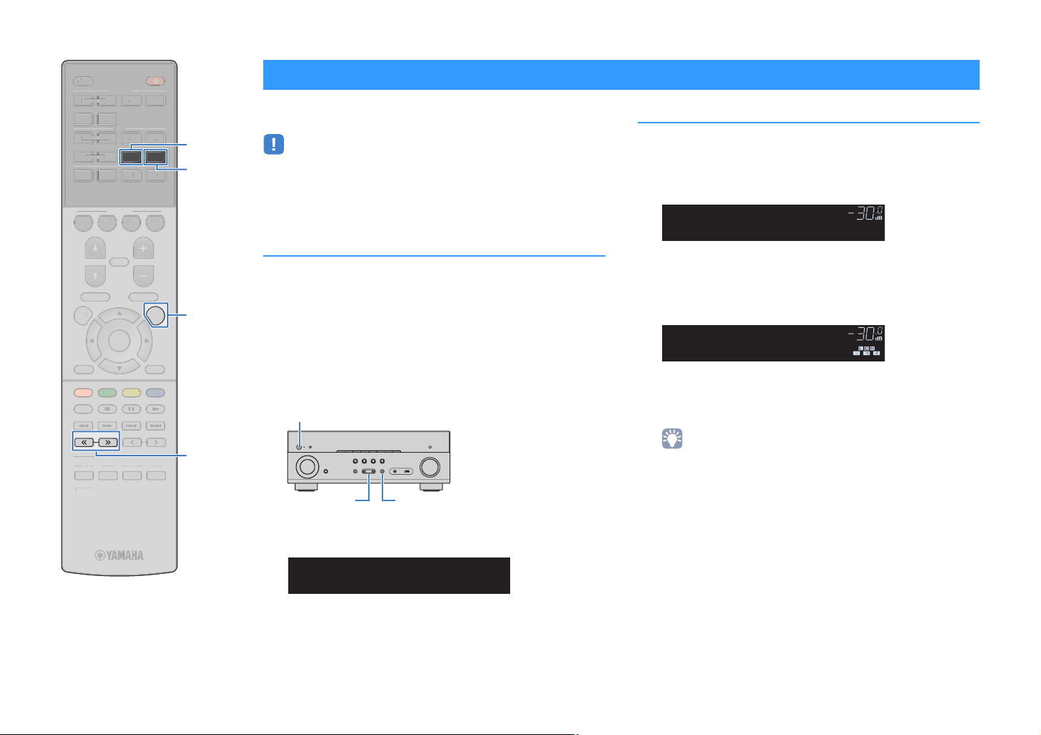
SLEEP
S
SS
6
SETU
P
U
M
EPOP-UP/
U
NE
T
UXUS
BLUETOO
SC
T
T
O
HDMI
AV
5
6
6
234
3
SE
T
E
Y
Y
N
U
E
L
OW
G
R
RE
D
S
P
LEE
HDMI
123 4
5 6
AV
1
123 4
56
5
BLUETOOTH
BD
BD
D
DVD
PROGRAM VOLUME
PROGRA
SETUP OPTION
RETURN
RETUR
RED
HOME
HOM
STRAIGHT DIRECT ENHANCER BASS
TRAIGHTDIRECTENHANCERBA
RAV546
RAV54
ZQ56680
ZQ56680
FM AM
TH
NET
B
SCENE
ENE
V
TV
NET
NE
VOLUM
MUTE
MUTE
TOP MENU
TOP MEN
TUNING PRESET
POP-UP/MENU
ENTER
YELLOWGREEN
YEL
EEN
PRE
AUXUSB
A
RADIO
RAD
MEN
DISPLA
DISPLAY
BLUE
BL
MEMORY
MEMOR
FM
AM
OPTION
TUNING
Listening to FM/AM radio
You can tune into a radio station by specifying its frequency or
selecting from registered radio stations.
• The radio frequencies differ depending on the country or region where the unit is
being used. The explanation of this section uses a display with frequencies used
in U.K. and Europe models.
• If you cannot obtain good reception on the radio, adjust the direction of the FM/AM
antennas.
Setting the frequency steps
(Asia model only)
At the factory, the frequency step setting is set to 50 kHz for FM and
9 kHz for AM. Depending on your country or region, set the
frequency steps to 100 kHz for FM and 10 kHz for AM.
Set the unit to standby mode.
1
When holding down STRAIGHT on the front panel,
2
press z (power).
z (power)
STRAIGHTPROGRAM
Press PROGRAM repeatedly to select “TU”.
3
CHARGE
OUT
ECO
ENHANCER
STEREO
TUNED
SLEEP
MUTE
VOL.
ADAPTIVE DRC
VIRTUAL
TU••••FM50/AM9
Selecting a frequency for reception
Press FM or AM to select a band.
1
“TUNER” is selected as the input source and then the
frequency currently selected is displayed.
CHARGE
OUT
ECO
ENHANCER
STEREO
TUNED
SLEEP
MUTE
VOL.
ADAPTIVE DRC
VIRTUAL
FM 87.50MHz
Press TUNING repeatedly to set a frequency.
2
Hold down the key for about a second to search stations
automatically.
CHARGE
OUT
ECO
ENHANCER
STEREO
TUNED
SLEEP
MUTE
VOL.
ADAPTIVE DRC
VIRTUAL
FM 98.50MHz
“TUNED” lights up when a signal is received from a radio
station.
“STEREO” also lights up when a stereo signal is received.
• You can switch between “Stereo” (stereo) and “Mono” (monaural) for FM
radio reception by selecting “FM Mode” (p.69) in the “Option” menu. When
the signal reception for an FM radio station is unstable, switching to
monaural may improve it.
• You can watch videos input from external devices while listening to radio by
selecting the video input jack in “Video Out” (p.71) in the “Option” menu.
Press STRAIGHT to select “FM100/AM10”.
4
Press z (power) to set the unit to standby mode
5
and turn it on again.
En 48
Page 49

“S
SLEEP
S
SS
6
SETU
P
U
M
EPOP-UP/
U
NE
T
UXUS
BLUETOO
SC
T
T
O
HDMI
AV
5
6
6
234
3
TU
G
E
Y
U
E
L
OW
G
R
RE
D
S
P
LEE
HDMI
123 4
5 6
AV
1
123 4
56
5
BLUETOOTH
BD
BD
D
DVD
FM AM
TH
NET
B
SCENE
ENE
V
TV
NET
NE
AUXUSB
A
RADIO
RAD
FM
AM
Registering favorite radio stations (presets)
You can register up to 40 radio stations as presets. Once you have
registered stations, you can easily tune into them by selecting their
preset numbers.
■ Registering radio stations automatically
(Auto Preset)
Automatically register FM radio stations with strong signals (up to
40 stations).
When the Auto Preset process finishes, “FINISH” appears and the
“Option” menu closes automatically.
CHARGE
OUT
ECO
ENHANCER
STEREO
TUNED
SLEEP
MUTE
VOL.
ADAPTIVE DRC
VIRTUAL
Auto Preset
■ Registering a radio station manually
Select a radio station manually and register it to a preset number.
Follow “Selecting a frequency for reception” (p.48)
1
to tune into the desired radio station.
PROGRAM VOLUME
PROGRA
TOP MENU
TOP MEN
SETUP OPTION
RETURN
RED
HOME
HOM
TUNING PRESET
STRAIGHT DIRECT ENHANCER BASS
TRAIGHTDIRECTENHANCERBA
RAV546
RAV54
ZQ56680
ZQ56680
VOLUM
MUTE
MUTE
POP-UP/MENU
MEN
ENTER
DISPLA
DISPLAY
YELLOWGREEN
YEL
EEN
BLUE
BL
MEMORY
NIN
OPTION
Cursor keys
Cursor keys
ENTER
RETURN
MEMORY
PRESET
• To register AM radio stations, follow “Registering a radio station manually”.
• (U.K. and Europe models only)
Only Radio Data System broadcasting stations are stored automatically by the
Auto Preset function.
Press FM or AM to select “TUNER” as the input
1
source.
Press OPTION.
2
Use the cursor keys to select “Auto Preset”.
3
CHARGE
OUT
ECO
ENHANCER
STEREO
TUNED
SLEEP
MUTE
VOL.
ADAPTIVE DRC
VIRTUAL
Auto Preset
To start the Auto Preset process, press ENTER.
4
The registration will start in 5 seconds. Press ENTER again
to start the registration immediately.
EARCH” appears during Auto Preset
CHARGE
OUT
ECO
ENHANCER
STEREO
TUNED
SLEEP
MUTE
VOL.
ADAPTIVE DRC
VIRTUAL
Hold down MEMORY for more than 2 seconds.
2
The first time that you do register a station, the selected
radio station will be registered to the preset number “01”.
Thereafter, each radio station you select will be registered
to the next empty (unused) preset number after the most
recently registered number.
CHARGE
OUT
ECO
ENHANCER
STEREO
TUNED
SLEEP
MUTE
VOL.
ADAPTIVE DRC
VIRTUAL
01:FM 98.50MHz
Preset number
• To select a preset number for registering, press MEMORY once after tuning
into the desired radio station, press PRESET to select a preset number, and
then press MEMORY again.
CHARGE
OUT
ECO
ENHANCER
STEREO
TUNED
SLEEP
MUTE
VOL.
ADAPTIVE DRC
VIRTUAL
02:Empty
“Empty” (not in use) or the frequency currently registered
01:FM 87.50MHz
Preset number from which to start the registration
• To specify the preset number from which to start the registration, press
PRESET or cursor keys (q/w) to select a preset number within 5 seconds
after step 4 (while “READY” is displayed) and then press ENTER (or just
wait for 5 seconds).
• To cancel the Auto Preset process, press RETURN.
En 49
Page 50
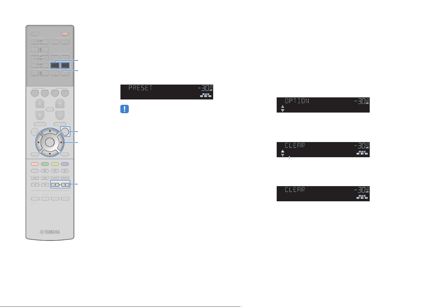
SLEEP
S
D
IRECT
SS
S
P
MUTE
M
E
U
E
T
UXUS
BLUETOO
DV
D
TV
NET
RADI
O
AV
5
6
5
6
234
234
E
Y
Y
RETURN
BLU
E
YELL
OW
G
REE
N
RE
D
S
P
LEE
HDMI
123 4
5 6
AV
123 4
56
BLUETOOTH
BD
DVD
PROGRAM VOLUME
PROGRA
SETUP OPTION
ETU
RETURN
RED
HOME
HOM
STRAIGHT DIRECT ENHANCER BASS
TRAIGHT
RAV546
RAV546
ZQ56680
ZQ56680
FM AM
TH
NET
N
B
SCENE
SCENE
TV
NET
VOLUM
MUTE
TOP MENU
TOP MENU
TUNING PRESET
TUNING
ENTER
YELLOWGREEN
ENHANCERBA
POP-UP/MENU
POP-UP/MEN
AUXUSB
A
RADIO
DISPLA
DISPLAY
BLUE
MEMORY
MEMOR
FM
AM
OPTION
Cursor keys
Cursor keys
ENTER
PRESET
■ Selecting a preset station
Tune into a registered radio station by selecting its preset number.
Press FM or AM to select “TUNER” as the input
1
source.
Press PRESET repeatedly to select the desired radio
2
station.
CHARGE
OUT
ECO
ENHANCER
STEREO
TUNED
SLEEP
MUTE
VOL.
ADAPTIVE DRC
VIRTUAL
01:FM 98.50MHz
• “No Presets” appears when no radio stations are registered.
■ Clearing preset stations
Clear radio stations registered to the preset numbers.
Press FM or AM to select “TUNER” as the input
1
source.
Press OPTION.
2
Use the cursor keys to select “Clear Preset” and
3
press ENTER.
CHARGE
OUT
ECO
ENHANCER
STEREO
TUNED
SLEEP
MUTE
VOL.
ADAPTIVE DRC
VIRTUAL
Clear Preset
Use the cursor keys (q/w) to select a preset station
4
to be cleared and press ENTER.
CHARGE
OUT
ECO
ENHANCER
STEREO
TUNED
SLEEP
MUTE
VOL.
ADAPTIVE DRC
VIRTUAL
01:FM 98.50MHz
Preset station to be cleared
If the preset station is cleared, “Cleared” appears and then
the next in-use preset number is displayed.
CHARGE
OUT
ECO
ENHANCER
STEREO
TUNED
SLEEP
MUTE
VOL.
ADAPTIVE DRC
VIRTUAL
01:Cleared
Repeat step 4 until all desired preset stations are
5
cleared.
To exit from the menu, press OPTION.
6
En 50
Page 51

SLEEP
S
D
IRECT
SS
6
SETU
P
U
M
EPOP-UP/
U
NE
T
U
X
SC
T
O
HDMI
AV
5
6
6
234
3
TU
G
SE
T
E
Y
Y
U
E
L
OW
G
R
RE
D
S
P
LEE
HDMI
123 4
5 6
AV
123 4
56
5
BLUETOOTH
BLUETOOTH
BD
BD
D
DVD
PROGRAM VOLUME
PROGRA
SETUP OPTION
RETURN
RED
HOME
HOM
STRAIGHT DIRECT ENHANCER BASS
TRAIGHT
RAV546
RAV54
ZQ56680
ZQ56680
FM AM
NET
USB
SCENE
ENE
TV
TV
NET
NE
D
VOLUM
MUTE
MUTE
TOP MENU
TOP MEN
TUNING PRESET
POP-UP/MENU
ENTER
YELLOWGREEN
YEL
EEN
NIN
PRE
ENHANCERBA
AUXUSB
A
RADIO
RAD
MEN
DISPLA
DISPLAY
BLUE
BL
MEMORY
MEMOR
OPTION
Cursor keys
Cursor keys
ENTER
RETURN
Radio Data System
tuning
(U.K. and Europe models only)
Radio Data System is a data transmission system used by FM
stations in many countries. The unit can receive various types of
Radio Data System data, such as “Program Service”, “Program
Type,” “Radio Text” and “Clock Time”, when it is tuned into a Radio
Data System broadcasting station.
■ Displaying the Radio Data System
information
Tune into the desired Radio Data System
1
broadcasting station.
• We recommend using “Auto Preset” to tune into the Radio Data System
broadcasting stations (p.49).
Press INFO.
2
Each time you press the key, the displayed item changes.
CHARGE
OUT
ECO
ENHANCER
STEREO
TUNED
SLEEP
MUTE
VOL.
ADAPTIVE DRC
VIRTUAL
Program Type
Item name
About 3 seconds later, the corresponding information for
the displayed item appears.
CHARGE
OUT
ECO
ENHANCER
STEREO
TUNED
SLEEP
MUTE
VOL.
ADAPTIVE DRC
VIRTUAL
CLASSICS
Information
• “Program Service”, “Program Type”, “Radio Text”, and “Clock Time” are not
displayed if the radio station does not provide the Radio Data System
service.
■ Receiving traffic information
automatically
When “TUNER” is selected as the input source, the unit
automatically receives traffic information. To enable this function,
follow the procedure below to set the traffic information station.
When “TUNER” is selected as the input source,
1
press OPTION.
Use the cursor keys to select “Traffic Program”
2
(Traffic Program) and press ENTER.
The traffic information station search will start in 5 seconds.
Press ENTER again to start the search immediately.
• To search upward/downward from the current frequency, press the cursor
keys (q/w) while “READY” is displayed.
• To cancel the search, press RETURN.
• Texts in parentheses denote indicators on the front display.
The following screen appears for about 3 seconds when the
search finishes.
CHARGE
OUT
ECO
ENHANCER
STEREO
TUNED
SLEEP
MUTE
VOL.
ADAPTIVE DRC
VIRTUAL
TP FM101.30MHz
Traffic information station (frequency)
Program Service Program service name
Program Type Current program type
• “TP Not Found” appears for about 3 seconds when no traffic information
stations are found.
Radio Text Information on the current program
Clock Time Current time
DSP Program Sound mode name
Audio Decoder Decoder name
Frequency Frequency
En 51
Page 52

SLEEP
S
SS
ENTER
S
P
O
U
MUTE
M
E
U
NE
T
U
X
O
I
V
5
6
5
6
234
234
E
Y
N
BLU
OW
G
S
P
LEE
HDMI
HDM
123 4
5 6
AV
A
123 4
56
BLUETOOTH
BD
DVD
FM AM
NET
USB
SCENE
SCENE
TV
NET
AUXUSB
A
RADIO
BLUETOOTH
Playing back music via BLUETOOTH
You can play back music files stored on a BLUETOOTH device
(such as smartphones) on the unit.
The unit
BLUETOOTH device
(such as smartphones)
Playback
BLUETOOTH
device music on the
unit
Follow the procedure below to establish a BLUETOOTH connection
between a BLUETOOTH device (such as smartphones) and the unit,
and play back music stored the BLUETOOTH device on the unit.
• The unit does not support video playback via BLUETOOTH.
MUTE
ENTER
VOLUM
POP-UP/MENU
POP-UP/MEN
YELLOWGREEN
PRESE
PTION
DISPLA
DISPLAY
BLUE
MEMORY
PROGRAM VOLUME
PROGRA
TOP MENU
TOP MEN
SETUP OPTION
ETU
RETURN
RETUR
RED
HOME
HOM
TUNING PRESET
TUNING
STRAIGHT DIRECT ENHANCER BASS
TRAIGHIRECTENHANCERBA
RAV546
RAV546
ZQ56680
ZQ56680
External device
External device
operation keys
operation keys
• To use the BLUETOOTH function, set “Bluetooth” (p.87) in the “Setup” menu to
“On”.
• For details on supported BLUETOOTH devices, see “Supported devices and file
formats” (p.105).
Press BLUETOOTH to select “Bluetooth” as the
1
input source.
On the BLUETOOTH device, select the unit (network
2
name of the unit) from the available device list.
A connection between the BLUETOOTH device and the
unit will be made.
If the pass key is required, enter the number “0000”.
On the BLUETOOTH device, select a song and start
3
playback.
The playback screen (artist name, album name and song
title) is displayed on the TV.
• If the unit detects the BLUETOOTH device previously connected, the unit
automatically connects to the BLUETOOTH device after Step 1. To establish
another BLUETOOTH connection, first terminate the current BLUETOOTH
connection.
• To terminate the BLUETOOTH connection, perform one of the following
operations.
– Perform the disconnect operation on the BLUETOOTH device.
– Select an input source other than “Bluetooth” on the unit.
– Select “Disconnect” in “Audio Receive” (p.74) in the “Setup” menu.
• You can use the external device operation keys (a, s, d, f, g) on
the remote control to control playback.
En 52
Page 53

SLEEP
S
SS
6
SETUPO
U
MUTEPROGRAMVOLUME
U
U
SC
O
5
6
6
3
3
M
G
E
Y
U
OW
G
S
P
LEE
HDMI
123 4
5 6
AV
A
123 4
56
5
BLUETOOTH
BLUETOOTH
BD
B
DVD
DVD
PROGRAM VOLUME
SETUP OPTION
TOP MENU
TOP MEN
TV
TV
SCENE
ENE
MUTE
FM AM
FMA
NET
NET
NE
POP-UP/MENU
POP-UP/MEN
AUXUSB
A
RADIO
RAD
PTION
USB
Playing back iPod music
You can play back iPod music on the unit using a USB cable
supplied with the iPod.
You can also play back iPod music in other methods. For details,
see the following pages.
• Playing back music with AirPlay (p.56)
• Playing back music stored on a BLUETOOTH device (p.52)
• AV CONTROLLER (p.6)
• You cannot play back iPod video on the unit.
• For details on playable iPod devices, see “Supported devices and file formats”
(p.105).
• The iPod charges while it is connected to the unit. If you set the unit to standby
mode while the iPod is charging, the iPod continues to charge up to 4 hours.
If “Network Standby” (p.86) in the “Setup” menu is set to “On”, it continues to
charge without limit.
• Disconnect the iPod from the USB jack when it is not in use.
Playback of
iPod
content
Follow the procedure below to operate the iPod contents and start
playback.
You can control the iPod with the menu displayed on the TV screen.
DISPLAY
BLUE
BL
MEMORY
MEMOR
Cursor keys
Cursor keys
ENTER
DISPLAY
RETURN
Connecting an
iPod
Connect your iPod to the unit with the USB cable supplied with the
iPod.
Connect the USB cable to the iPod.
1
Connect the USB cable to the USB jack.
2
The unit (front)
STRAIGHT
(CONNECT)
AUX
5V 1A
AUDIO
• Operations with TV screen are available only when your TV is connected to the
unit via HDMI. If not, carry out operations while viewing the front display, or directly
operate the iPod itself in the simple play mode (p.55).
• “_” (underscore) will be displayed for characters not supported by the unit.
Press USB to select “USB” as the input source.
1
The browse screen (p.54) is displayed on the TV.
• If playback is ongoing on your iPod, the playback screen is displayed.
Use the cursor keys to select an item and press
2
ENTER.
ENTER
RETURN
YELLOWGREEN
YEL
EEN
RED
HOME
HOM
TUNING PRESET
TUNIN
STRAIGHT DIRECT ENHANCER BASS
TRAIGHTIRECTENHANCERBA
RAV546
RAV54
ZQ56680
ZQ56680
PRESE
If a song is selected, playback starts and the playback
screen (p.54) is displayed.
• To return to the previous screen, press RETURN.
• To switch the screen mode browse/playback/off, press DISPLAY.
CHARGE
OUT
ECO
ENHANCER
STEREO
TUNED
SLEEP
MUTE
VOL.
ADAPTIVE DRC
VIRTUAL
• To operate the iPod manually to select content or control playback, switch to
the simple play mode (p.55).
Connected
En 53
Page 54
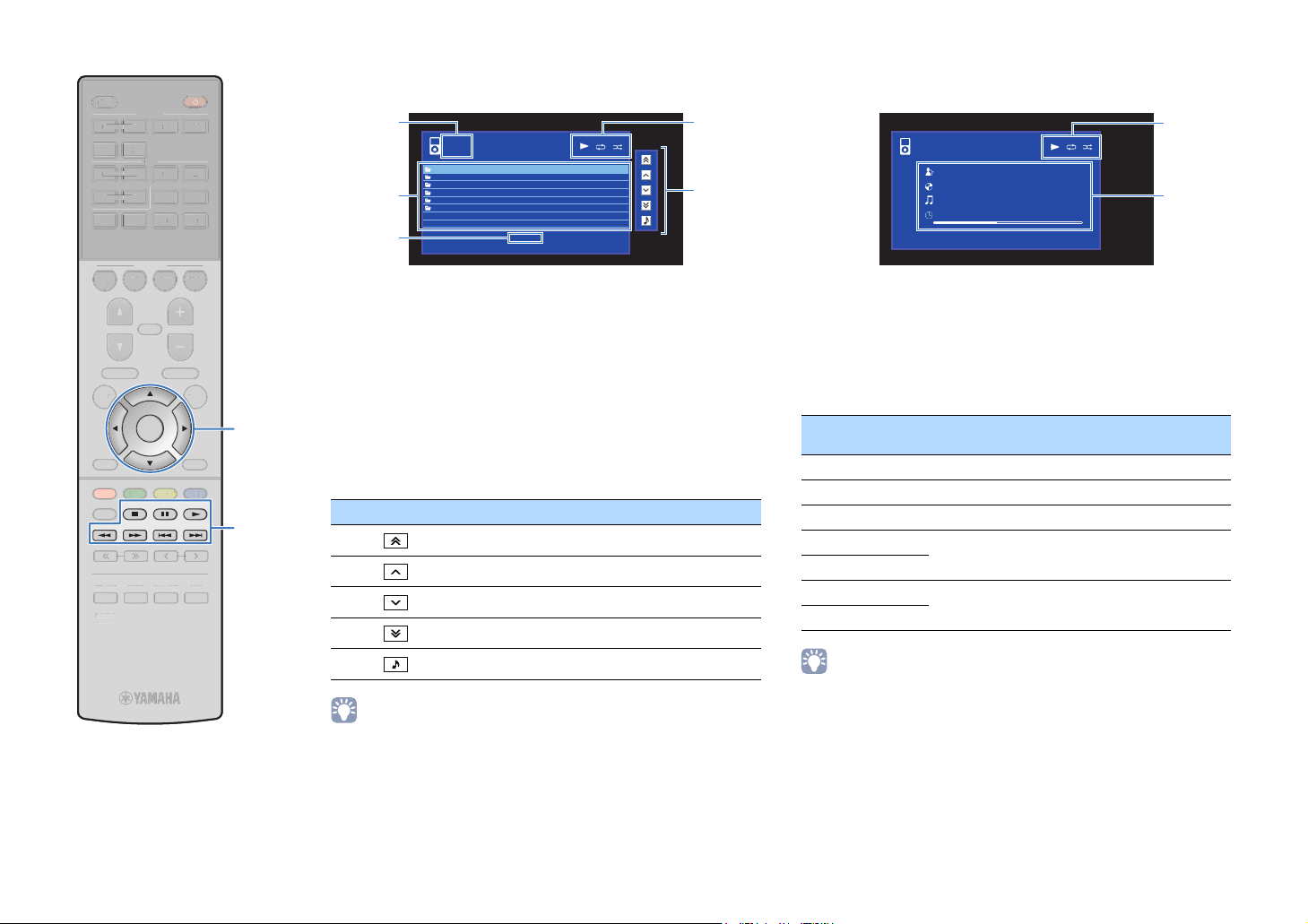
SLEEP
S
SS
ZQ
P
O
U
MUTE
M
E
U
NE
T
U
X
O
I
V
5
6
5
6
234
234
E
Y
N
BLU
OW
G
S
P
LEE
HDMI
HDM
123 4
5 6
AV
A
123 4
56
BLUETOOTH
BLUETOOTH
BD
DVD
PROGRAM VOLUME
PROGRA
SETUP OPTION
SETU
RETURN
RETUR
RED
HOME
HOM
STRAIGHT DIRECT ENHANCER BASS
TRAIGHIRECTENHANCERBA
RAV546
RAV546
ZQ56680
56680
FM AM
NET
USB
SCENE
SCENE
TV
NET
VOLUM
MUTE
TOP MENU
TOP MEN
TUNING PRESET
TUNING
ENTER
POP-UP/MENU
POP-UP/MEN
YELLOWGREEN
PRESE
AUXUSB
A
RADIO
PTION
DISPLA
DISPLAY
BLUE
MEMORY
Cursor keys
Cursor keys
ENTER
External device
External device
operation keys
operation keys
■ Browse screen
1
iPod
Music
Playlists
Artists
Albums
Songs
2
Genres
Composers
3
1 List name
2 Contents list
Displays the list of iPod content. Use the cursor keys to select an item and
press ENTER to confirm the selection.
3 Item number/total
4 Status indicators
Display the current repeat/shuffle settings (p.55) and playback status
(such as play/pause).
5 Operation menu
Press the cursor key (r) and then use the cursor keys (q/w) to select an
item. Press ENTER to confirm the selection.
Icon Function
Moves 10 pages backward.
Moves to the previous page of the list.
Moves to the next page of the list.
Moves 10 pages forward.
1/6
[DISPLAY] to Now Playing
4
5
■ Playback screen
iPod
Now Playing
Artist Name
Album Name
Song Title
2:30
[DISPLAY] : Screen Off
5:10
1 Status indicators
Display the current repeat/shuffle settings (p.55) and playback status
(such as play/pause).
2 Playback information
Displays the artist name, album name, song title, and elapsed time/song
length.
Use the following remote control keys to control playback.
External device
operation keys
a Resumes playback from pause.
s Stops playback.
d Stops playback temporarily.
f
g
h
j
Function
Skips forward/backward.
Searches forward/backward (by holding down).
1
2
Moves to the playback screen.
• A content name of a current playback is displayed on the front display. To switch
the displayed item, press INFO (p.68).
• A content selected by the cursor is displayed on the front display.
En 54
Page 55
SLEEP
S
SS
ZQ
S
P
U
MUTE
M
E
U
NE
T
U
X
O
I
V
5
6
5
6
234
234
E
Y
Y
BLU
OW
G
S
P
LEE
HDMI
HDM
123 4
5 6
AV
A
123 4
56
BLUETOOTH
BLUETOOTH
BD
DVD
PROGRAM VOLUME
PROGRA
SETUP OPTION
ETU
RETURN
RED
HOME
HOM
STRAIGHT DIRECT ENHANCER BASS
TRAIGHIRECTENHANCERBA
RAV546
RAV546
ZQ56680
56680
FM AM
NET
USB
SCENE
SCENE
TV
NET
VOLUM
MUTE
TOP MENU
TOP MEN
TUNING PRESET
TUNING
ENTER
POP-UP/MENU
POP-UP/MEN
YELLOWGREEN
PRESE
AUXUSB
A
RADIO
DISPLA
DISPLAY
BLUE
MEMORY
MEMOR
OPTION
Cursor keys
Cursor keys
ENTER
RETURN
■ Operating the iPod itself (simple play)
Press OPTION.
1
Use the cursor keys to select “iPod Mode” and
2
press ENTER.
The TV menu screen turns off and iPod operations are
enabled.
To display the TV menu screen, select “iPod Mode” and
press ENTER again.
Operate your iPod itself to start playback.
3
■ Repeat/shuffle settings
You can configure the repeat/shuffle settings of your iPod.
• During simple play, configure the repeat/shuffle settings directly on your iPod.
When “USB” is selected as the input source, press
1
OPTION.
Use the cursor keys to select “Repeat” (Repeat) or
2
“Shuffle” (Shuffle) and press ENTER.
• To return to the previous screen during menu operations, press RETURN.
• Texts in parentheses denote indicators on the front display.
Use the cursor keys (e/r) to select a setting.
3
Item Setting Function
Off (Off) Turns off the repeat function.
Repeat
(Repeat)
Shuffle
(Shuffle)
One (One)
All (All)
Off (Off) Turns off the shuffle function.
Songs (Songs)
Albums
(Albums)
Plays back the current song repeatedly.
“c” appears in the TV screen.
Plays back all songs repeatedly.
“v” appears in the TV screen.
Plays back songs in random order.
“x” appears in the TV screen.
Plays back albums in random order.
“x” appears in the TV screen.
To exit from the menu, press OPTION.
4
En 55
Page 56

Playing back music with AirPlay
The AirPlay function allows you to play back iTunes or iPhone/iPad/iPod touch music on
the unit via network.
iTunes
PC
Router
The unit
(Wired network or wireless network)
iPhone/iPad/iPod touch
• To use this function, the unit and your PC or iPod must be connected to the same router (p.24). You can
check whether the network parameters (such as the IP address) are properly assigned to the unit in
“Information” (p.85) in the “Setup” menu.
• If the iPod does not recognize the unit, check your network environment (p.24).
• This section describes “iPod touch”, “iPhone” and “iPad” as the “iPod”. “iPod” refers to “iPod touch”,
“iPhone” and “iPad”, unless otherwise specified.
• For details on supported iPod devices, see “Supported devices and file formats” (p.105).
Playback of
Follow the procedure below to play back iTunes/iPod music contents on the unit.
Turn on the unit, and start iTunes on the PC or display the playback
1
iTunes/iPod
music contents
screen on the iPod.
If the iTunes/iPod recognizes the unit, the AirPlay icon ( ) appears.
iTunes (example) iPod iOS7/iOS8 (example) iPod iOS6 (example)
• If the icon does not appear, check whether the unit and PC/iPod are connected to the router properly.
On the iTunes/iPod, click (tap) the AirPlay icon and select the unit
2
(network name of the unit) as the audio output device.
Select a song and start playback.
3
The unit automatically selects “AirPlay” as the input source and starts playback.
The playback screen is displayed on the TV.
• The playback screen is available only when your TV is connected to the unit via
HDMI
.
En 56
Page 57

SLEEP
S
SS
ENTER
S
P
O
U
MUTE
M
E
U
NE
T
U
X
O
I
V
5
6
5
6
234
234
E
Y
N
BLU
OW
G
S
P
LEE
HDMI
HDM
123 4
5 6
AV
A
123 4
56
BLUETOOTH
BLUETOOTH
BD
DVD
PROGRAM VOLUME
PROGRA
SETUP OPTION
ETU
TOP MENU
TOP MEN
FM AM
NET
AUXUSB
SCENE
SCENE
MUTE
NET
VOLUM
POP-UP/MENU
POP-UP/MEN
A
RADIO
PTION
USB
TV
• You can turn on the unit automatically when starting playback on iTunes or iPod
by setting “Network Standby” (p.86) in the “Setup” menu to “On”.
• You can edit the network name (the unit’s name on the network) displayed on
iTunes/iPod in “Network Name” (p.86) in the “Setup” menu.
• If you select the other input source on the unit during playback, playback on the
iTunes/iPod stops automatically.
• You can adjust the unit’s volume from the iTunes/iPod during playback. To disable
volume controls from iTunes/iPod, set “Volume Interlock” (p.71) in the “Option”
menu to “Off”.
Caution
• When you use iTunes/iPod controls to adjust volume, the volume may be
unexpectedly loud. This could result in damage to the unit or speakers. If the
volume suddenly increases during playback, stop playback on the iTunes/iPod
immediately.
■ Playback screen
Use the following remote control keys to control playback.
External device
operation keys
a Resumes playback from pause.
s Stops playback.
d Stops playback temporarily.
f
g
• To control iTunes playback with the remote control of the unit, you need to
configure the iTunes preferences to enable iTunes control from remote speakers
in advance.
Function
Skips forward/backward.
iTunes (example of English version)
ENTER
DISPLA
RETURN
RETUR
RED
HOME
HOM
TUNING PRESET
TUNING
STRAIGHT DIRECT ENHANCER BASS
TRAIGHIRECTENHANCERBA
RAV546
RAV546
ZQ56680
ZQ56680
DISPLAY
YELLOWGREEN
BLUE
MEMORY
PRESE
External device
External device
operation keys
operation keys
1 Playback indicator
2 Playback information
Displays the artist name, album name, song title, and elapsed time/song
length.
AirPlay
Now Playing
Artist Name
Album Name
Song Title
2:30
1
2
5:30
Check this box
En 57
Page 58

SLEEP
S
SS
6
SETUPO
U
MUTEPROGRAMVOLUME
U
U
SC
O
5
6
6
3
3
M
G
E
Y
U
OW
G
S
P
LEE
HDMI
123 4
5 6
AV
A
123 4
56
5
BLUETOOTH
BLUETOOTH
BD
B
DVD
DVD
PROGRAM VOLUME
SETUP OPTION
RETURN
RED
HOME
HOM
FM AM
FMA
NET
SCENE
ENE
TV
TV
NET
NE
MUTE
TOP MENU
TOP MEN
TUNING PRESET
TUNIN
POP-UP/MENU
POP-UP/MEN
ENTER
YELLOWGREEN
YEL
EEN
PRESE
AUXUSB
A
RADIO
RAD
PTION
DISPLAY
BLUE
BL
MEMORY
MEMOR
USB
Cursor keys
Cursor keys
ENTER
DISPLAY
RETURN
Playing back music stored on a USB storage device
You can play back music files stored on a USB storage device on
the unit.
• For details on playable USB devices, see “Supported devices and file formats”
(p.105).
Connecting a
Connect the USB storage device to the USB jack.
1
The unit (front)
STRAIGHT
(CONNECT)
USB
storage device
AUX
5V 1A
AUDIO
Playback of
Follow the procedure below to operate the USB storage device
contents and start playback.
You can control the USB memory device with the menu displayed
on the TV screen.
• Operations with TV screen are available only when your TV is connected to the
unit via HDMI.
• “_” (underscore) will be displayed for characters not supported by the unit.
Press USB to select “USB” as the input source.
1
The browse screen (p.59) is displayed on the TV.
• If playback is ongoing on your USB storage device, the playback screen is
displayed.
Use the cursor keys to select an item and press
2
ENTER.
If a song is selected, playback starts and the playback
screen (p.59) is displayed.
USB
storage device contents
STRAIGHT DIRECT ENHANCER BASS
TRAIGHTIRECTENHANCERBA
RAV546
RAV54
ZQ56680
ZQ56680
USB storage device
• To return to the previous screen, press RETURN.
• To switch the screen mode browse/playback/off, press DISPLAY.
• Files not supported by the unit cannot be selected.
• If the USB storage device contains many files, it may take time to load them. In
this case, “Loading...” appears in the front display.
• Stop playback of the USB storage device before disconnect it from the USB jack.
• Connect a USB storage device directly to the USB jack of the unit. Do not use
extension cables.
En 58
Page 59

SLEEP
S
SS
ZQ
P
O
U
MUTE
M
E
U
NE
T
U
X
O
I
V
5
6
5
6
234
234
E
Y
N
BLU
OW
G
S
P
LEE
HDMI
HDM
123 4
5 6
AV
A
123 4
56
BLUETOOTH
BLUETOOTH
BD
DVD
PROGRAM VOLUME
PROGRA
SETUP OPTION
SETU
RETURN
RETUR
RED
HOME
HOM
STRAIGHT DIRECT ENHANCER BASS
TRAIGHIRECTENHANCERBA
RAV546
RAV546
ZQ56680
56680
FM AM
NET
USB
SCENE
SCENE
TV
NET
VOLUM
MUTE
TOP MENU
TOP MEN
TUNING PRESET
TUNING
ENTER
POP-UP/MENU
POP-UP/MEN
YELLOWGREEN
PRESE
AUXUSB
A
RADIO
PTION
DISPLA
DISPLAY
BLUE
MEMORY
Cursor keys
Cursor keys
ENTER
External device
External device
operation keys
operation keys
■ Browse screen
14
2
3
1 List name
2 Contents list
Displays the list of USB storage device contents. Use the cursor keys to
select an item and press ENTER to confirm the selection.
3 Item number/total
4 Status indicators
Display the current repeat/shuffle settings (p.60) and playback status
(such as play/pause).
5 Operation menu
Press the cursor key (r) and then use the cursor keys (q/w) to select an
item. Press ENTER to confirm the selection.
Icon Function
USB
Top
Blues
Classical
Electronica
Jazz
Pop
Rock
Soundtrack
Speaking
1/12
[DISPLAY] to Now Playing
Moves 10 pages backward.
5
■ Playback screen
1 Status indicators
Display the current repeat/shuffle settings (p.60) and playback status
(such as play/pause).
2 Playback information
Displays the artist name, album name, song title, and elapsed time.
Use the following remote control keys to control playback.
External device
operation keys
a Resumes playback from pause.
s Stops playback.
d Stops playback temporarily.
f
g
Moves to the previous page of the list.
Moves to the next page of the list.
Moves 10 pages forward.
• A content name of a current playback is displayed on the front display. To switch
the displayed item, press INFO (p.68).
USB
Now Playing
Artist Name
Album Name
Song Title
2:30
[DISPLAY] : Screen Off
Function
Skips forward/backward.
1
2
Moves to the playback screen.
• A content selected by the cursor is displayed on the front display.
En 59
Page 60

SLEEP
S
SS
ZQ
S
P
U
MUTE
M
E
U
NE
T
U
X
O
I
V
5
6
5
6
234
234
E
Y
Y
BLU
OW
G
S
P
LEE
HDMI
HDM
123 4
5 6
AV
A
123 4
56
BLUETOOTH
BLUETOOTH
BD
DVD
PROGRAM VOLUME
PROGRA
SETUP OPTION
ETU
RETURN
RED
HOME
HOM
STRAIGHT DIRECT ENHANCER BASS
TRAIGHIRECTENHANCERBA
RAV546
RAV546
ZQ56680
56680
FM AM
NET
USB
SCENE
SCENE
TV
NET
VOLUM
MUTE
TOP MENU
TOP MEN
TUNING PRESET
TUNING
ENTER
POP-UP/MENU
POP-UP/MEN
YELLOWGREEN
PRESE
AUXUSB
A
RADIO
DISPLA
DISPLAY
BLUE
MEMORY
MEMOR
OPTION
Cursor keys
Cursor keys
ENTER
RETURN
■ Repeat/shuffle settings
You can configure the repeat/shuffle settings for playback of USB
storage device contents.
When “USB” is selected as the input source, press
1
OPTION.
Use the cursor keys to select “Repeat” (Repeat) or
2
“Shuffle” (Shuffle) and press ENTER.
• To return to the previous screen during menu operations, press RETURN.
• Texts in parentheses denote indicators on the front display.
Use the cursor keys (e/r) to select a setting.
3
Item Setting Function
Off (Off) Turns off the repeat function.
Repeat
One (One)
(Repeat)
All (All)
Off (Off) Turns off the shuffle function.
Shuffle
(Shuffle)
To exit from the menu, press OPTION.
4
On (On)
Plays back the current song repeatedly.
“c” appears on the TV screen.
Plays back all songs in the current album
(folder) repeatedly.
“v” appears on the TV screen.
Plays back songs in the current album
(folder) in random order.
“x” appears on the TV screen.
En 60
Page 61

Playing back music stored on media servers (PCs/NAS)
You can play back music files stored on your PC or DLNA-compatible NAS on the unit.
• To use this function, the unit and your PC must be connected to the same router (p.24). You can check
whether the network parameters (such as the IP address) are properly assigned to the unit in “Information”
(p.85) in the “Setup” menu.
• The audio may be interrupted while using the wireless network connection. In this case, use the wired
network connection.
• For details on playable file formats, see “Supported devices and file formats” (p.105).
Media sharing setup
To play back music files stored on your PC or DLNA-compatible NAS, first you need to
configure the media sharing setting on each music server.
■ For a PC with Windows Media Player installed
❑ For Windows Media Player 12
Start Windows Media Player 12 on your PC.
1
Select “Stream”, then “Turn on media streaming”.
2
Click “Turn on media streaming”.
3
Select “Allowed” from the drop-down list next to the unit’s model
4
name.
❑ For Windows Media Player 11
Start Windows Media Player 11 on your PC.
1
Select “Library”, then “Media Sharing”.
2
Check the “Share my media to” box, select the unit’s icon, and click
3
“Allow”.
Click “OK” to exit.
4
• For details on media sharing settings, refer to Windows Media Player help.
■ For a PC or a NAS with other DLNA server software
installed
Refer to the instruction manual for the device or software and configure the media
sharing settings.
Click “OK” to exit.
5
En 61
Page 62

SLEEP
S
SS
S
P
O
U
MUTE
M
E
U
U
X
O
I
V
5
6
5
6
234
234
E
Y
BLU
OW
G
S
P
LEE
HDMI
HDM
123 4
5 6
AV
A
123 4
56
BLUETOOTH
BLUETOOTH
BD
DVD
PROGRAM VOLUME
PROGRA
SETUP OPTION
ETU
RETURN
RED
HOME
HOM
STRAIGHT DIRECT ENHANCER BASS
TRAIGHIRECTENHANCERBA
RAV546
RAV546
ZQ56680
ZQ56680
FM AM
NET
USB
SCENE
SCENE
TV
NET
VOLUM
MUTE
TOP MENU
TOP MEN
TUNING PRESET
TUNING
ENTER
POP-UP/MENU
POP-UP/MEN
YELLOWGREEN
PRESE
AUXUSB
A
RADIO
PTION
DISPLAY
BLUE
MEMORY
MEMOR
NET
Cursor keys
Cursor keys
ENTER
DISPLAY
RETURN
Playback of PC music contents
Follow the procedure below to operate the PC music contents and
start playback.
You can control the PC/NAS with the menu displayed on the TV
screen.
• Operations with TV screen are available only when your TV is connected to the
unit via HDMI. If not, carry out operations while viewing the front display.
• “_” (underscore) will be displayed for characters not supported by the unit.
Press NET repeatedly to select “SERVER” as the
1
input source.
The browse screen (p.62) is displayed on the TV.
• If playback of a music file selected from the unit is ongoing on your PC, the
playback screen is displayed.
Use the cursor keys to select a music server and
2
press ENTER.
Use the cursor keys to select an item and press
3
ENTER.
If a song is selected, playback starts and the playback
screen (p.63) is displayed.
• To return to the previous screen, press RETURN.
• To switch the screen mode browse/playback/off, press DISPLAY.
• Files not supported by the unit cannot be selected.
■ Browse screen
14
2
3
1 List name
2 Contents list
Displays the list of PC content. Use the cursor keys to select an item and
press ENTER to confirm the selection.
3 Item number/total
4 Status indicators
Display the current repeat/shuffle settings (p.63) and playback status
(such as play/pause).
5 Operation menu
Press the cursor key (r) and then use the cursor keys (q/w) to select an
item. Press ENTER to confirm the selection.
Icon Function
SERVER
NAS A
Blues
Classical
Electronica
Jazz
Pop
Rock
Soundtrack
Speaking
1/14
[DISPLAY] to Now Playing
Moves 10 pages backward.
Moves to the previous page of the list.
Moves to the next page of the list.
Moves 10 pages forward.
Moves to the playback screen.
5
En 62
Page 63

SLEEP
S
SS
S
P
U
MUTE
M
E
U
NE
T
U
X
O
V
5
6
5
6
234
234
G
E
E
Y
BLU
OW
G
S
P
LEE
HDMI
HDMI
123 4
5 6
AV
A
123 4
56
BLUETOOTH
BLUETOOTH
BD
DVD
PROGRAM VOLUME
PROGRA
SETUP OPTION
ETU
RETURN
RED
HOME
HOM
STRAIGHT DIRECT ENHANCER BASS
TRAIGHIRECTENHANCERBA
RAV546
RAV546
ZQ56680
ZQ56680
FM AM
NET
USB
SCENE
SCENE
TV
NET
VOLUM
MUTE
TOP MENU
TOP MEN
TUNING PRESET
TUNIN
ENTER
POP-UP/MENU
POP-UP/MEN
YELLOWGREEN
PRES
AUXUSB
A
RADIO
DISPLA
DISPLAY
BLUE
MEMORY
OPTION
Cursor keys
Cursor keys
ENTER
RETURN
External device
External device
operation keys
operation keys
■ Playback screen
SERVER
Now Playing
Artist Name
Album Name
Song Title
2:30
[DISPLAY] : Screen Off
1 Status indicators
Display the current repeat/shuffle settings (p.63) and playback status
(such as play/pause).
2 Playback information
Displays the artist name, album name, song title, and elapsed time.
Use the following remote control keys to control playback.
External device
operation keys
a Resumes playback from pause.
s Stops playback.
d Stops playback temporarily.
f
g
• You can also use a DLNA-compatible Digital Media Controller (DMC) to control
playback. For details, see “DMC Control” (p.86).
Function
Skips forward/backward.
1
2
■ Repeat/shuffle settings
You can configure the repeat/shuffle settings for the playback of PC
music content.
When “SERVER” is selected as the input source,
1
press OPTION.
Use the cursor keys to select “Repeat” (Repeat) or
2
“Shuffle” (Shuffle) and press ENTER.
• To return to the previous screen during menu operations, press RETURN.
• Text in parentheses denotes indicators on the front display.
Use the cursor keys (e/r) to select a setting.
3
Item Setting Function
Off (Off) Turns off the repeat function.
Repeat
One (One)
(Repeat)
All (All)
Off (Off) Turns off the shuffle function.
Shuffle
(Shuffle)
To exit from the menu, press OPTION.
4
On (On)
Plays back the current song repeatedly.
“c” appears on the TV screen.
Plays back all songs in the current album
(folder) repeatedly.
“v” appears on the TV screen.
Plays back songs in the current album
(folder) in random order.
“x” appears on the TV screen.
En 63
Page 64
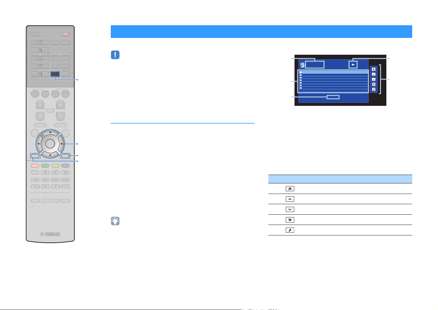
SLEEP
S
SS
S
P
O
U
MUTE
M
E
U
U
X
O
I
V
5
6
5
6
234
234
E
Y
BLU
OW
G
S
P
LEE
HDMI
HDM
123 4
5 6
AV
A
123 4
56
BLUETOOTH
BLUETOOTH
BD
DVD
PROGRAM VOLUME
PROGRA
SETUP OPTION
ETU
RETURN
RED
HOME
HOM
STRAIGHT DIRECT ENHANCER BASS
TRAIGHIRECTENHANCERBA
RAV546
RAV546
ZQ56680
ZQ56680
FM AM
NET
USB
SCENE
SCENE
TV
NET
VOLUM
MUTE
TOP MENU
TOP MEN
TUNING PRESET
TUNING
ENTER
POP-UP/MENU
POP-UP/MEN
YELLOWGREEN
PRESE
AUXUSB
A
RADIO
PTION
DISPLAY
BLUE
MEMORY
MEMOR
NET
Cursor keys
Cursor keys
ENTER
DISPLAY
RETURN
Listening to Internet radio
You can listen to Internet radio stations from all over the world.
• Operations with TV screen are available only when your TV is connected to the
unit via HDMI. If not, carry out operations while viewing the front display.
• To use this function, the unit must be connected to the Internet (p.24). You can
check whether the network parameters (such as the IP address) are properly
assigned to the unit in “Information” (p.85) in the “Setup” menu.
• You may not be able to receive some Internet radio stations.
• The unit uses the vTuner Internet radio station database service.
• This service may be discontinued without notice.
Playback of Internet radio
Follow the procedure below to select an Internet radio station and
start playback.
You can control the Internet radio with the menu displayed on the
TV screen.
Press NET repeatedly to select “NET RADIO” as the
1
input source.
The browse screen (p.64) is displayed on the TV.
Use the cursor keys to select an item and press
2
ENTER.
If an Internet radio station is selected, playback starts and
the playback screen (p.65) is displayed.
• To return to the previous screen, press RETURN.
• To switch the screen mode browse/playback/off, press DISPLAY.
■ Browse screen
14
2
3
1 List name
2 Contents list
Displays the list of Internet radio content. Use the cursor keys to select an
item and press ENTER to confirm the selection.
3 Item number/total
4 Playback indicator
5 Operation menu
Press the cursor key (r) and then use the cursor keys (q/w) to select an
item. Press ENTER to confirm the selection.
Icon Function
NET RADIO
Top
Bookmarks
Locations
Genres
New Stations
Popular Stations
Podcasts
Help
1/7
[DISPLAY] to Now Playing
Moves 10 pages backward.
Moves to the previous page of the list.
Moves to the next page of the list.
Moves 10 pages forward.
Moves to the playback screen.
5
En 64
Page 65

SLEEP
S
SS
ZQ
ENTER
P
O
U
MUTE
M
E
U
NE
T
U
X
O
V
5
6
5
6
234
234
G
E
E
Y
Y
N
BLU
OW
G
S
P
LEE
HDMI
HDMI
123 4
5 6
AV
A
123 4
56
BLUETOOTH
BLUETOOTH
BD
DVD
PROGRAM VOLUME
PROGRA
FM AM
NET
USB
SCENE
SCENE
TV
NET
VOLUM
MUTE
AUXUSB
A
RADIO
■ Playback screen
NET RADIO
Now Playing
Station Name
Album Name
Song Title
2:30
[DISPLAY] : Screen Off
1 Playback indicator
2 Playback information
Displays the station name, album name, song title, and elapsed time.
1
2
TOP MENU
TOP MEN
SETUP OPTION
SETU
RETURN
RETUR
RED
HOME
HOM
TUNING PRESET
TUNIN
STRAIGHT DIRECT ENHANCER BASS
TRAIGHIRECTENHANCERBA
RAV546
RAV546
ZQ56680
56680
ENTER
POP-UP/MENU
POP-UP/MEN
YELLOWGREEN
PRES
PTION
DISPLA
DISPLAY
BLUE
MEMORY
MEMOR
External device
External device
operation keys
operation keys
• Use the external device operation key (s) to stop playback.
• Some information may not be available depending on the station.
En 65
Page 66
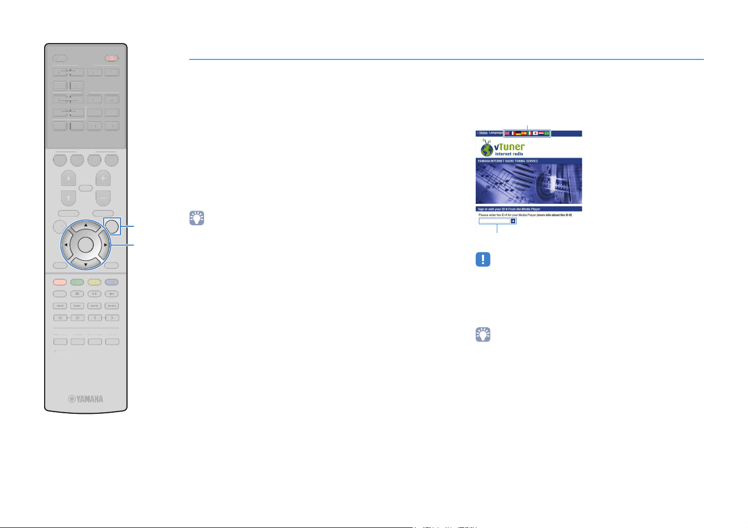
SLEEP
S
D
IRECT
SS
6
SETU
P
U
M
EPOP-UP/
U
NE
T
U
X
SC
T
O
HDMI
AV
5
6
6
234
3
TU
G
SE
T
E
Y
Y
N
U
E
L
OW
G
R
RE
D
S
P
LEE
HDMI
123 4
5 6
AV
123 4
56
5
BLUETOOTH
BLUETOOTH
BD
BD
D
DVD
FM AM
NET
USB
SCENE
ENE
TV
TV
NET
NE
D
AUXUSB
A
RADIO
RAD
Registering favorite Internet radio stations (bookmarks)
You can register your favorite Internet radio stations to the
“Bookmarks” folder.
■ Registering the station with the Option
menu
Follow the procedure below to register your favorite station to the
“Bookmarks” folder.
While listening to Internet radio, press OPTION.
1
Access the vTuner website
3
(http://yradio.vtuner.com/) with the web browser on
your PC and enter the vTuner ID.
You can switch the language.
PROGRAM VOLUME
PROGRA
TOP MENU
TOP MEN
SETUP OPTION
RETURN
RETUR
RED
HOME
HOM
TUNING PRESET
STRAIGHT DIRECT ENHANCER BASS
TRAIGHT
RAV546
RAV54
ZQ56680
ZQ56680
VOLUM
MUTE
MUTE
POP-UP/MENU
MEN
ENTER
DISPLA
DISPLAY
YELLOWGREEN
YEL
EEN
BLUE
BL
MEMORY
MEMOR
NIN
PRE
ENHANCERBA
OPTION
Cursor keys
Cursor keys
ENTER
Use the cursor keys to select “Bookmark On” and
2
press ENTER.
• On the playback screen, the current station is added to the “Bookmarks” folder. On
the browse screen, the station selected in the list is added to the “Bookmarks”
folder.
• To remove stations from the “Bookmarks” folder, select the station in the folder and
then “Bookmark Off”.
■ Registering the station on the vTuner
website
You can also register your favorite Internet radio stations on the
vTuner website.
Select any of Internet radio stations on the unit.
1
This operation is necessary to register the radio station for
the first time.
Check the vTuner ID of the unit.
2
You can find the vTuner ID in “Information” (p.85) in the
“Setup” menu.
Enter the vTuner ID in this area.
• To use this feature, you need to create your personal account. Create your
account using your e-mail address.
Register your favorite radio stations.
4
Click the “Add” icon (❤+) next to the station name.
• To remove the station from the “Bookmarks” folder, select “Bookmarks” in
the Home screen, and then click the “Remove” icon (❤–) next to the station
name.
En 66
Page 67
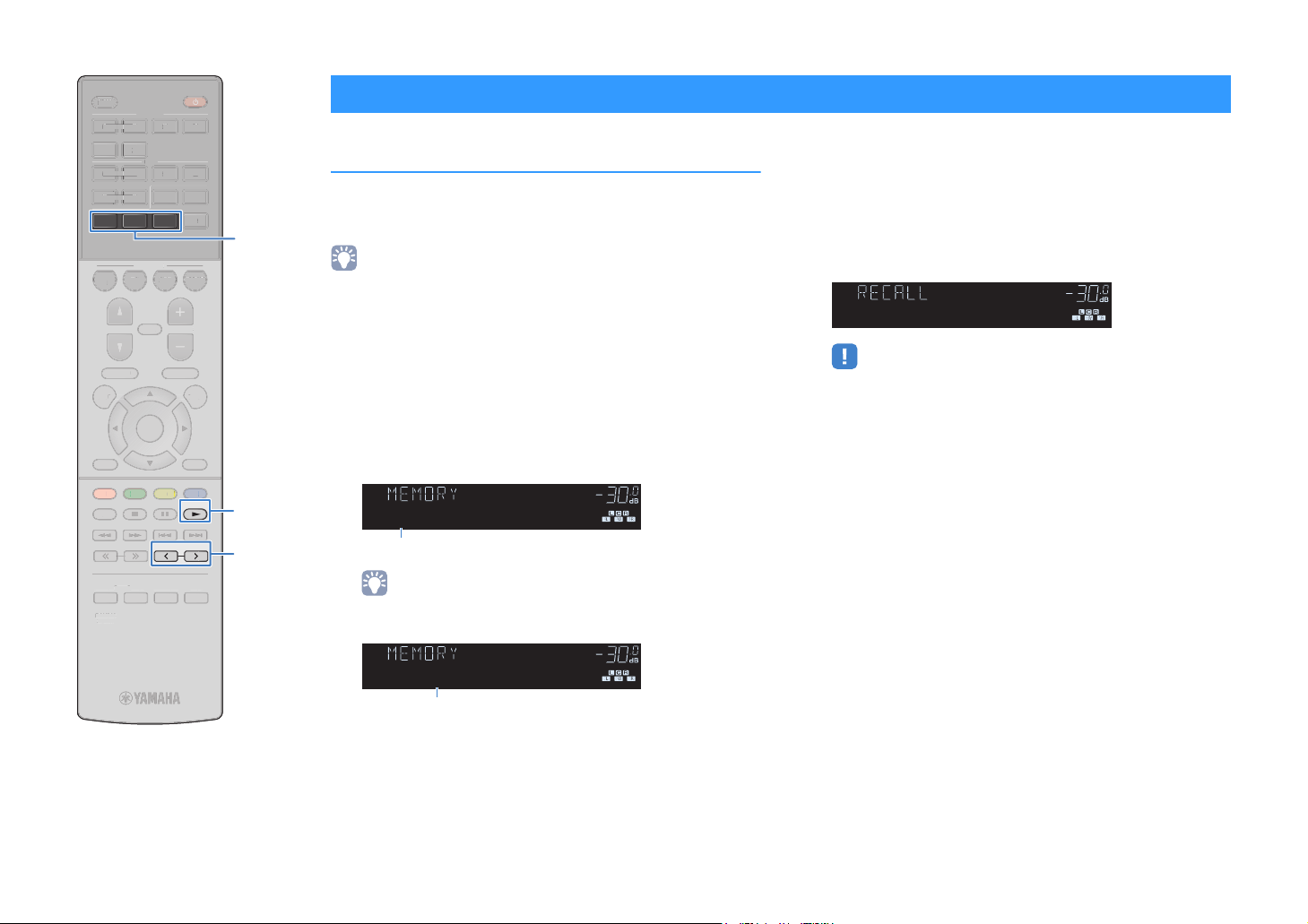
SLEEP
S
SS
6
SETUPO
U
MUTEPROGRAMVOLUME
U
U
SC
O
5
6
6
3
3
M
G
E
Y
N
U
OW
G
S
P
LEE
HDMI
123 4
5 6
AV
A
123 4
56
5
BLUETOOTH
BD
B
DVD
DVD
PROGRAM VOLUME
SETUP OPTION
RETURN
RETUR
RED
HOME
HOM
STRAIGHT DIRECT ENHANCER BASS
TRAIGHTIRECTENHANCERBA
RAV546
RAV54
ZQ56680
ZQ56680
FM AM
FMA
NET
SCENE
ENE
TV
TV
NET
NE
MUTE
TOP MENU
TOP MEN
TUNING PRESET
TUNIN
REEN
ENTER
ENTER
POP-UP/MENU
POP-UP/MEN
YELLOWGREEN
YEL
AUXUSB
A
RADIO
RAD
PTION
DISPLA
DISPLAY
BLUE
BL
MEMORY
BLUETOOTH
USB
NET
MEMORY
PRESET
Useful functions
Registering favorite items (shortcut)
You can register up to 40 favorite USB and network contents as
shortcuts and access them directly by selecting the shortcut
numbers.
• You can also use the “Bookmark” feature to register Internet radio stations (p.66).
• BLUETOOTH and AirPlay are applied to the input source. You cannot register
particular songs in the device individually.
■ Registering an item
Select a desired item and register it to a shortcut number.
Play back a song or a radio station to be registered.
1
Hold down MEMORY for 3 seconds.
2
CHARGE
OUT
ECO
ENHANCER
SLEEP
MUTE
VOL.
ADAPTIVE DRC
VIRTUAL
01:Empty
Shortcut number (flashes)
• To change a shortcut number to which the item will be registered, use
PRESET to select the shortcut number after step 2.
CHARGE
OUT
ECO
ENHANCER
SLEEP
MUTE
VOL.
ADAPTIVE DRC
VIRTUAL
02:Empty
“Empty” (not in use) or item currently registered
■ Recalling a registered item
Recall a registered item by selecting the shortcut number.
Press BLUETOOTH, NET or USB.
1
Press PRESET repeatedly to select a desired item.
2
CHARGE
OUT
ECO
ENHANCER
SLEEP
MUTE
VOL.
ADAPTIVE DRC
VIRTUAL
01:USB
• “No Presets” appears when no items are registered.
• The registered item cannot be recalled in the following cases.
– A USB storage device which contains the registered item is not connected
to this unit.
– A PC which contains the registered item is turned off or not connected to
the network.
– The registered network content is temporarily unavailable or out of service.
– The registered item (file) has been deleted or moved to another location.
– A BLUETOOTH connection cannot be established.
• When you register music files stored on a USB storage device or a PC, this
unit memorizes the relative position of the music files in the folder. If you
have added or deleted any music files to or from the folder, this unit may not
recall the music file correctly. In such cases, register the items again.
To confirm the registration, press MEMORY.
3
En 67
Page 68

Switching information on the front display
Press INFO.
1
Each time you press the key, the displayed item changes.
CHARGE
OUT
ECO
ENHANCER
STEREO
TUNED
SLEEP
MUTE
VOL.
ADAPTIVE DRC
VIRTUAL
Audio Decoder
Item name
About 3 seconds later, the corresponding information for the displayed item
appears.
CHARGE
OUT
ECO
ENHANCER
STEREO
TUNED
SLEEP
MUTE
VOL.
ADAPTIVE DRC
VIRTUAL
†‡Pro Logic
Information
• Available items vary depending on the selected input source. The displayed item can also be applied
separately to each input source group.
Input source group Item
HDMI
AV
AUX
BLUETOOTH
USB
SERVER
AirPlay
NET RADIO
TUNER
* The name of the audio decoder currently activated is displayed. If no audio decoder is activated, “Decoder
Off” appears.
Input (input source name), DSP Program (sound mode name), Audio
Decoder (decoder name*)
Song (song title), Artist (artist name), Album (album name), DSP Program
(sound mode name), Audio Decoder (decoder name*)
During simple playback of iPod:
Input (input source name), DSP Program (sound mode name), Audio
Decoder (decoder name)
Song (song title), Album (album name), Station (station name), DSP
Program (sound mode name), Audio Decoder (decoder name*)
Frequency (frequency), DSP Program (sound mode name), Audio Decoder
(decoder name*)
(U.K. and Europe models only)
Radio Data System
Data System
broadcasting station (p.51).
data is also available when the unit is tuned into a
Radio
En 68
Page 69

Configuring playback settings for different playback sources (Option menu)
You can configure separate playback settings for different playback sources. This
menu is available on the front panel (or on the TV screen), allowing you to easily
configure settings during playback.
Press OPTION.
1
CHARGE
OUT
ECO
ENHANCER
STEREO
TUNED
SLEEP
MUTE
VOL.
ADAPTIVE DRC
VIRTUAL
Input Select
Front display
Option
Input Select
Tone Control
DSP/Surround
Volume Trim
Lipsync
Signal Info
Audio In
TV screen
Use the cursor keys to select an item and press ENTER.
2
• To return to the previous screen during menu operations, press RETURN.
Use the cursor keys (e/r) to select a setting.
3
To exit from the menu, press OPTION.
4
Option
• Available items vary depending on the selected input source.
• Text in parentheses denotes indicators on the front display.
• Default settings are underlined.
• Depending on the region of purchase, some menu items for audio streaming services are also available.
For details, refer to each manual on the supplied CD-ROM.
Item Function Page
Input Select (Input) Switches the input source. 70
Tone Control (Tone Control)
DSP/Surround
(DSP/Surround)
Volume Trim
(Volume Trim)
Lipsync (Lipsync)
Signal Info (Signal Info) Displays information about the video/audio signal. 71
Audio In (Audio)
Video Out (Video) Selects a video to be output with radio sounds. 71
FM Mode (FM Mode)
Auto Preset (Auto Preset)
Clear Preset (Clear Preset) Clear radio stations registered to preset numbers. 50
Traffic Program
(Traffic Program)
iPod Mode (iPod Mode) Switches the iPod operation mode. 55
Repeat (Repeat)
menu items
Adjusts the high-frequency range and low-frequency
range of sounds.
Program (PRG) Select the sound programs and stereo playback. 44
Sur.Decode
(SrDec)
DSP Level
(DSP Level)
Adaptive DRC
(A.DRC)
Enhancer
(Enhancer)
Input Trim
(In.Trim)
Subwoofer Trim
(SW.Trim)
Select which surround decoder is used when
Sur.Decode is selected as the program.
Adjusts the sound field effect level. 70
Sets whether the dynamic range (from maximum to
minimum) is automatically adjusted when the volume
is adjusted.
Enables/disables Compressed Music Enhancer. 70
Corrects volume differences between input sources. 70
Fine-adjusts the subwoofer volume. 71
Enables/disables the “Lipsync” setting in the “Setup”
menu.
Combines the video jack of the selected input source
with an audio jack of others.
Switches between “
Automatically registers FM radio stations with strong
signals as presets.
(U.K. and Europe models only)
Automatically searches for a traffic information station.
Configures the repeat setting for the iPod (p.55),
USB storage device (p.60), or media server (p.63).
Stereo
” and “
Mono
” for FM radio reception.
70
46
70
71
71
48
49
51
—
En 69
Page 70

Item Function Page
Shuffle (Shuffle)
Volume Interlock (Interlock)
Bookmark On (Bookmark On)
Bookmark Off (Bookmark Off)
Configures the shuffle setting for the iPod (p.55),
USB storage device (p.60), or media server (p.63).
Enables/disables volume controls from iTunes/iPod
via AirPlay.
Adds your favorite Internet radio station to the
“Bookmarks” folder, or removes it from the
“Bookmarks” folder.
—
71
66
■ Input Select (Input)
Switches the input source. Press ENTER to switch to the selected input source.
Choices
HDMI 1-6, AV 1-6, TUNER, USB, SERVER, NET RADIO, Airplay, (network sources), Bluetooth,
AUX
■ Tone Control (Tone Control)
Adjusts the high-frequency range (Treble) and low-frequency range (Bass) of sounds.
Choices
Treble (Treble), Bass (Bass)
Setting range
-6.0 dB to Bypass (Bypass)
• You can also adjust the tone with the front panel controls. Press TONE CONTROL to select “Treble” or
“Bass”, then press PROGRAM to make an adjustment.
• If you set an extreme value, sounds may not match those from other channels.
to +6.0 dB (0.5 dB increments)
■ DSP/Surround (DSP/Surround)
Configures the sound field program and surround settings.
❑ DSP Level (DSP Level)
Adjusts the sound field effect level.
Setting range
-6 dB to 0 dB
to +3 dB
❑ Adaptive DRC (A.DRC)
Sets whether the dynamic range (from maximum to minimum) is automatically adjusted
when the volume level is adjusted. When it is set to “On”, it is useful for listening to
playback at a low volume at night.
Settings
On (On) Automatically adjusts the dynamic range.
Off (Off)
The dynamic range is not automatically adjusted.
If “On” is selected, the dynamic range becomes narrow at a low volume and wide at a
high volume.
❑ Enhancer (Enhancer)
Enables/disables Compressed Music Enhancer (p.47).
• This setting is applied separately to each input source.
• You can also use ENHANCER on the remote control to enable/disable Compressed Music Enhancer
(p.47).
Settings
Off (Off) Disables Compressed Music Enhancer.
On (On) Enables Compressed Music Enhancer.
Default
TUNER, USB, SERVER, NET RADIO, AirPlay (network sources), Bluetooth: On (On)
Others: Off (Off)
■ Volume Trim (Volume Trim)
Fine-adjusts volume difference between input sources or subwoofer volume.
❑ Input Trim (In.Trim)
Corrects volume differences between input sources. If you are bothered by volume
differences when switching between input sources, use this function to correct it.
• This setting is applied separately to each input source.
Setting range
-6.0 dB to 0.0 dB
to +6.0 dB (0.5 dB increments)
En 70
Page 71

❑ Subwoofer Trim (SW.Trim)
Fine-adjusts the subwoofer volume.
Setting range
-6.0 dB to 0.0 dB
to +6.0 dB (0.5 dB increments)
■ Lipsync (Lipsync)
Enables/disables the adjustment configured in “Lipsync” (p.81) in the “Setup” menu.
• This setting is applied separately to each input source.
Settings
Off (Off) Disables the “Lipsync” adjustment.
On (On) Enables the “Lipsync” adjustment.
Default
AirPlay: Off (Off)
Others: On (On)
■ Signal Info (Signal Info)
Displays information about the video/audio signal.
Choices
Format (FORMAT) Audio format of the input signal
The number of source channels in the input signal
Channel (CHANNEL)
Sampling
(SAMPLING)
Bitrate (BITRATE) The amount of data per second of the input bitstream signal
Video In (VIDEO IN) Type and resolution of the input digital signal
Video Out
(VIDEO OUT)
(front/surround/LFE)
For example, “3/2/0.1” means 3 front channels, 2 surround channels,
and LFE.
The number of samples per second of the input digital signal
Type and resolution of the output digital signal
■ Audio In (Audio)
Combines the video jack of the selected input source (HDMI 1-6 or AV 1-6) with an
audio jack of others. For example, use this function in the following cases.
• Connecting a playback device that supports HDMI video output, but not HDMI audio
output
• Connecting a playback device that has component video jacks and analog stereo
jacks (such as game consoles)
Input sources
HDMI 1-6, AV 1-6
■ Setup procedure
See “Changing the combination of video/audio input jacks” (p.21).
■ Video Out (Video)
Selects a video to be output with the selected audio source. For example, you can
watching the video while listening to the radio.
Input sources
TUNER, USB, Bluetooth, AUX
Settings
Off (Off) Does not output video.
HDMI 1-6,
AV 1-6
Outputs video input through the corresponding video input jacks.
■ Volume Interlock (Interlock)
Enables/disables volume controls from iTunes/iPod via AirPlay.
Settings
Off (Off) Disables volume controls from iTunes/iPod.
Limited (Ltd)
Full (Full)
Enables volume controls from iTunes/iPod within the limited range
(-80 dB to -20 dB and mute).
Enables volume controls from iTunes/iPod in the full range
(-80 dB to +16.5 dB and mute).
• To switch the information on the front display, press the cursor keys (q/w) repeatedly.
En 71
Page 72

CONFIGURATIONS
Configuring various functions (Setup menu)
You can configure the unit’s various function with the menu displayed on the TV screen.
• Operations with TV screen are available only when your TV is connected to the unit via HDMI. If not, carry
out operations while viewing the front display.
• If new firmware is available, the envelope icon (p) appears in the screen.
Press SETUP.
1
Use the cursor keys to select a menu and press ENTER.
2
Setup
Speaker
HDMI
Sound
ECO
Function
Network
Bluetooth
Language
Use the cursor keys to select an item and press ENTER.
3
Setup
Speaker
HDMI
Sound
ECO
Function
Network
Bluetooth
Language
Configuration
Distance
Level
Equalizer
Test Tone
Configuration
Distance
Level
Equalizer
Test Tone
Use the cursor keys (e/r) to select a setting and press ENTER.
4
To exit from the menu, press SETUP.
5
• To return to the previous screen during menu operations, press RETURN.
En 72
Page 73

Setup
Menu Item Function Page
Speaker
HDMI Configuration
menu items
Configuration
Distance Sets the distance between each speaker and listening position. 76
Level Adjusts the volume of each speaker. 76
Equalizer Adjusts the tone with an equalizer. 77
Test Tone Enables/disables the test tone output. 77
Subwoofer Selects whether or not a subwoofer is connected. 75
Front Selects the size of the front speakers. 75
Center Selects whether or not a center speaker is connected and its size. 75
Surround Selects whether or not surround speakers are connected and their size. 75
Crossover Sets the lower limit of the low-frequency component that can be output from speakers whose size is set to “Small”. 75
Subwoofer Phase Sets the phase of the subwoofer. 76
Extra Bass Enables/disables Extra Bass. 76
Virtual CINEMA FRONT Selects whether to use the front 5-channel speaker (Virtual CINEMA FRONT) configuration. 76
HDMI Control Enables/disables HDMI Control. 78
Audio Output Selects a device to output audio. 78
Standby Through Selects whether to output videos/audio (input through HDMI jacks) to the TV when the unit is in standby mode. 78
TV Audio Input Selects an audio input jack of the unit to be used for TV audio input. 78
Standby Sync Selects whether to use HDMI control to link the standby behavior of the TV and the unit. 78
ARC Enables/disables ARC. 79
SCENE Enables/disables SCENE link playback. 79
En 73
Page 74

Menu Item Function Page
CINEMA DSP 3D Mode Enables/disables CINEMA DSP 3D. 80
Panorama Enables/disables the broadening effect of the front sound field. 80
DSP Parameter
Center Width Adjusts the broadening effect of the center sound field. 80
Dimension Adjusts the difference in level between the front and surround sound fields. 80
Center Image Adjusts the center orientation level (broadening effect) of the front sound field. 80
Sound
Lipsync
Select Selects the method to adjust the delay between video and audio output. 81
Adjustment Adjusts the delay between video and audio output manually. 81
Scale Switches the scale of the volume display. 81
Volume
Dynamic Range Selects the dynamic range adjustment method for bitstream audio (Dolby Digital and DTS signals) playback. 81
Max Volume Sets the maximum volume to prevent excessive loudness. 81
Initial Volume Sets the initial volume for when this receiver is turned on. 81
ECO
Auto Power Standby Set the amount of time for the auto-standby function. 82
ECO Mode Enables/disables the eco mode (power saving mode). 82
Input Rename Changes the input source name displayed on the front display. 83
Input Skip Set which input source is skipped when operating the INPUT key. 83
Function
Dimmer Adjusts the brightness of the front display. 83
Memory Guard Prevents accidental changes to the settings. 83
Remote Color Key Set the unit's functions for the RED/GREEN/YELLOW/BLUE key of the remote control. 84
Information Displays the network information on the unit. 85
Network Connection Selects the network connection method. 85
IP Address Configures the network parameters (such as IP address). 85
Network
MAC Address Filter Sets the MAC address filter to limit access to the unit from other network devices. 86
DMC Control Selects whether to allow a DLNA-compatible Digital Media Controller (DMC) to control playback. 86
Network Standby Selects whether to enable/disable the function that turns on the unit from other network devices. 86
Network Name Edits the network name (the unit’s name on the network) displayed on other network devices. 86
Network Update Updates the firmware via the network. 87
Bluetooth Enables/disables the BLUETOOTH functions. 87
Bluetooth
Audio Receive Disconnect Terminates the BLUETOOTH connection between the BLUETOOTH device (such as smartphones) and the unit. 52
Bluetooth Standby Selects whether to enable/disable the function that turns on the unit from BLUETOOTH devices (BLUETOOTH standby). 87
Language Select an on-screen menu language. 88
En 74
Page 75

Speaker
Configures the speaker settings manually.
• Default settings are underlined.
■ Configuration
Configures the output characteristics of the speakers.
• When you configure the speaker size, select “Large” if the woofer diameter of your speaker is 16 cm
(6-1/4”) or larger or “Small” if it is smaller than 16 cm (6-1/4”).
Subwoofer
Selects whether or not a subwoofer is connected.
Settings
Use
None
Front
Selects the size of the front speakers.
Settings
Small
Large
• “Front” is automatically set to “Large” when “Subwoofer” is set to “None”.
Select this option when a subwoofer is connected.
The subwoofer will produce LFE (low-frequency effect) channel audio
and low-frequency components from other channels.
Select this option when no subwoofer is connected.
The front speakers will produce LFE (low-frequency effect) channel
audio and low-frequency components from other channels.
Select this option for small speakers.
The subwoofer will produce front channel low-frequency components
(configurable in “Crossover”).
Select this option for large speakers.
The front speakers will produce all of the front channel frequency
components.
Center
Selects whether or not a center speaker is connected and its size.
Settings
Small
Large
None
Select this option for small speakers.
The subwoofer or front speakers will produce center channel
low-frequency components (configurable in “Crossover”).
Select this option for large speakers.
The center speaker will produce all of the center channel frequency
components.
Select this option when no center speaker is connected.
The front speakers will produce center channel audio.
Surround
Selects whether or not surround speakers are connected and their sizes.
Settings
Small
Large
None
Select this option for small speakers.
The subwoofer or front speakers will produce surround channel
low-frequency components (configurable in “Crossover”).
Select this option for large speakers.
The surround speakers will produce all of the surround channel
frequency components.
Select this option when no surround speakers are connected.
The front speakers will produce surround channel audio. Virtual
CINEMA DSP works when you select a sound program.
Crossover
Sets the lower limit of the low-frequency components that can be output from a
speaker whose size is set to “Small”. A frequency sound lower than the specified
value will be produced from the subwoofer or front speakers.
Settings
40 Hz, 60 Hz, 80 Hz
• If the volume and crossover frequency are adjustable on your subwoofer, set the volume to half and
crossover frequency to maximum.
, 90 Hz, 100 Hz, 110 Hz, 120 Hz, 160 Hz, 200 Hz
En 75
Page 76

Subwoofer Phase
Sets the phase of the subwoofer. When the bass sound is lacking or unclear,
switch the subwoofer phase.
Settings
Normal Does not reverse the subwoofer phase.
Reverse Reverses the subwoofer phase.
Extra Bass
Enables/disables Extra Bass. When Extra Bass is enabled, you can enjoy
enhanced bass sounds, regardless of the size of the front speakers and the
presence or absence of the subwoofer.
Settings
Off Disables Extra Bass.
On Enables Extra Bass.
• You can also use BASS on the remote control to enable/disable Extra Bass (p.47).
Virtual CINEMA FRONT
Selects whether to use the front 5-channel speaker (Virtual CINEMA FRONT)
configuration.
Settings
Off Disables the front 5-channel speaker configuration.
On Enables the front 5-channel speaker configuration.
■ Distance
Sets the distance between each speaker and listening position so that sounds from the
speakers reach the listening position at the same time. First, select the unit of distance
from “Meter” or “Feet”.
Choices
Front L, Front R, Center, Surround L, Surround R, Subwoofer
Setting range
0.30 m to 24.00 m (1.0 ft to 80.0 ft), 0.05 m (0.2 ft) increments
Default
Front L, Front R, Subwoofer: 3.00 m (10.0 ft)
Center: 2.60 m (8.6 ft)
Others: 2.40 m (8.0 ft)
■ Level
Adjusts the volume of each speaker.
Choices
Front L, Front R, Center, Surround L, Surround R, Subwoofer
Setting range
-10.0 dB to +10.0 dB (0.5 dB increments)
Default
Front L, Front R, Subwoofer: 0.0 dB
Others: -1.0 dB
• Select “On” only when utilizing the Virtual CINEMA FRONT configuration (p.13).
• This setting is not available when “Surround” is set to “None”.
En 76
Page 77

■ Equalizer
Adjusts the tone with an equalizer.
EQ Select
Selects the type of equalizer to be used.
Settings
PEQ
GEQ
Off Does not use the equalizer.
• “PEQ” is available only when the YPAO has been performed (p.27).
■ Manual equalizer adjustment
Set “EQ Select” to “GEQ”.
1
Use the cursor keys (q/w) to select “Channel” and the cursor keys (e/r) to
2
select the desired speaker channel.
Use the cursor keys (q/w) to select the desired band (frequency) and the
3
cursor keys (e/r) to adjust the gain.
Setting range
-6.0 dB to +6.0 dB
Applies the parametric equalizer values obtained by the YPAO
measurement (p.27).
Select this option when you want to adjust the equalizer manually.
For details, see “Manual equalizer adjustment”.
■ Test Tone
Enables/disables the test tone output. Test tone output helps you to adjust the speaker
balance or equalizer while confirming its effect.
Settings
Off Does not output test tones.
On
Outputs test tones automatically when you adjust the speaker balance
or equalizer.
Equalizer
EQ Select
GEQ Edit
Channel
63Hz
160Hz
400Hz
1kHz
2.5kHz
6.3kHz
16kHz
Back:RETURN
To exit from the menu, press SETUP.
4
GEQ
Front L
En 77
Page 78

HDMI
Configures the HDMI settings.
• Default settings are underlined.
■ Configuration
HDMI Control
Enables/disables HDMI Control (p.107).
Settings
Off Disables HDMI Control.
On
• To use HDMI control, you need to perform the HDMI Control link setup (p.107) after connecting HDMI
Control-compatible devices.
Audio Output
Selects a device to output audio.
• This setting is available only when “HDMI Control” is set to “Off”.
Amp
Enables/disables the audio output from the speakers connected to the unit.
Settings
Off Disables the audio output from the speakers.
On
HDMI OUT (TV)
Enables/disables the audio output from a TV connected to the HDMI OUT jack.
Settings
Off
On Enables the audio output from the TV.
Enables HDMI Control.
Configure the settings in “TV Audio Input”, “Standby Sync”, “ARC”,
and “SCENE”.
Enables the audio output from the speakers.
Disables the audio output from the TV.
Standby Through
Select whether to output videos/audio (input through HDMI jacks) to the TV when
the unit is in standby mode. If this function is set to “On” or “Auto”, you can use the
input selection keys (HDMI 1–6) to select an HDMI input even when the unit is in
standby mode (the standby indicator on the unit blinks).
Settings
Off
Auto
On
(When “HDMI Control” is set to “Off”)
Does not output videos/audio to the TV.
Automatically selects whether to output videos/audio depending on
the status of the connected device.
Outputs videos/audio to the TV.
(The unit consumes more power than when “Off” is selected.)
TV Audio Input
Selects an audio input jack of the unit to be used for TV audio input when “HDMI
Control” is set to “On”. The unit’s input source automatically switches to TV audio
when the TV input is switched to its built-in tuner.
Settings
AV 1–6
Default
AV4
• When using ARC to input TV audio to the unit, you cannot use the input jacks selected here for
connecting an external device because the input will be used for TV audio input.
Standby Sync
Select whether to use HDMI control to link the standby behavior of the TV and the
unit when “HDMI Control” is set to “On”.
Settings
Off Does not set the unit to standby mode when the TV is turned off.
On Sets the unit to standby mode when the TV is turned off.
Auto
Sets the unit to standby mode when the TV is turned off only when the
unit is receiving TV audio or HDMI signals.
En 78
Page 79

ARC
Enables/disables ARC (p.18) when “HDMI Control” is set to “On”.
Settings
Off Disables ARC.
On
• You do not need to change this setting normally. In case noises are produced from the speakers
connected to the unit because TV audio signals input to the unit via ARC are not supported by the
unit, set “ARC” to “Off” and use the TV’s speakers.
Enables ARC.
SCENE
Enables/disable SCENE link playback when “HDMI Control” is set to “On”.
When SCENE link playback is enabled, HDMI Control-compatible devices
connected to the unit via HDMI automatically works as follows, with a scene
selection.
• TV: turning on and displaying video from the playback device
• Playback device: starting playback
Choices (SCENE keys)
BD/DVD, TV, NET, RADIO
Settings
Off Disables SCENE link playback for the selected SCENE key.
On Enables SCENE link playback for the selected SCENE key.
Default
BD/DVD, TV: On
NET, RADIO: Off
• SCENE link playback may not work properly due to the compatibility between devices. We
recommend using TV and playback devices from the same manufacturer so that HDMI Control works
more effectively.
En 79
Page 80

Sound
Configures the audio output settings.
• Default settings are underlined.
■ DSP Parameter
Configures the surround decoder settings.
CINEMA DSP 3D Mode
Enables/disables CINEMA DSP 3D (p.44). If this function is set to “On”, CINEMA
DSP 3D functions with the selected sound programs (except 2ch Stereo and 5ch
Stereo).
Settings
Off Disables CINEMA DSP 3D.
On
Panorama
Enables/disables the broadening effect of the front sound field. When this function
is enabled, you can wrap front left/right channel sounds around the field and
generate a spacious sound field in combination with the surround sound field. This
setting is effective when “bPLII Music” is selected.
Settings
Off Disables the broadening effect of the front sound field.
On Enables the broadening effect of the front sound field.
Enables CINEMA DSP 3D.
Dimension
Adjusts the difference in level between the front and surround sound fields. Higher
to strengthen the front sound field and lower to strengthen the surround sound
field. This setting is effective when “bPLII Music” is selected.
Setting range
to +3
-3 to 0
Center Image
Adjusts the center orientation level (broadening effect) of the front sound field.
Higher to strengthen the center orientation level (less broadening effect) and lower
to weaken (more broadening effect). This setting is effective when “Neo:6 Music” is
selected.
Setting range
to 1.0
0.0 to 0.3
Center Width
Adjusts the broadening effect of the center sound field. Higher to enhance the
broadening effect, and lower to reduce it (closer to center). This setting is effective
when “bPLII Music” is selected.
Setting range
0 to 3
to 7
En 80
Page 81

■ Lipsync
Adjusts the delay between video and audio output.
■ Volume
Configures the volume settings.
• You can enable/disable the Lipsync function by input sources in “Lipsync” (p.71) in the “Option” menu.
Select
Selects the method to adjust the delay between video and audio output.
Setting range
Select this option when you want to adjust the delay between video
Manual
Auto
• “Select” is automatically set to “Manual” depending on the TV connected to the unit.
and audio output manually.
Adjust the audio output timing in “Adjustment”.
Adjusts the delay between video and audio output automatically when
a TV that supports an automatic lipsync function is connected to the
unit via HDMI.
If necessary, you can fine-adjust the audio output timing in
“Adjustment”.
Adjustment
Adjusts the delay between video and audio output manually when “Select” is set to
“Manual”. You can fine-adjust the audio output timing when “Select” is set to
“Auto”.
Setting range
0 ms
to 500 ms (1 ms increments)
Scale
Switches the scale of the volume display.
Settings
dB Displays the volume in the “dB” unit.
0-97 Displays the volume in the numeric value (0.5 to 97.0).
Dynamic Range
Selects the dynamic range adjustment method for bitstream audio (Dolby Digital
and DTS signals) playback.
Settings
Maximum Produces audio without adjusting the dynamic range.
Standard Optimizes the dynamic range for regular home use.
Sets the dynamic range for clear sound even at night or at low
Min/Auto
volumes.
When playing back Dolby TrueHD signals, the dynamic range is
automatically adjusted based on the input signal information.
Max Volume
Sets the maximum volume to prevent excessive loudness.
Setting range
-30.0 dB to +15.0 dB (5.0 dB increments), +16.5 dB
[50.0 to 95.0 (5.0 increments), 97.0]
Initial Volume
Sets the initial volume when the receiver is turned on.
Settings
Off
Mute Sets the unit to mute the audio output.
-80.0 dB to +16.5 dB
(0.5 dB increments)
[0.5 to 97.0
(0.5 increments)]
Sets the level to the volume level of the unit when it last entered
standby mode.
Sets the level to the specified volume level.
En 81
Page 82

ECO
Configures the power supply settings.
• Default settings are underlined.
■ Auto Power Standby
Set the amount of time for the auto-standby function.
Settings
Off Does not set the unit to standby mode automatically.
20 minutes
2 hours, 4 hours,
8 hours, 12 hours
Default
U.K. and Europe models: 20 minutes
Other models: Off
• Just before the unit enters standby mode, “AutoPowerStdby” appears and then countdown starts in
the front display.
■ ECO Mode
Enables/disables the eco (power saving) mode.
When the eco mode is enabled, you can reduce the unit’s power consumption.
Settings
Off
On Enables the eco mode.
Sets the unit to standby mode when you have not operated the unit
and the unit has not detected any input signal for the specified time.
Sets the unit to standby mode when you have not operated the unit for
the specified time.
Disables the eco mode.
• Be sure to press ENTER to restart the unit after selecting a setting. The new setting will take effect after the
unit is restarted.
• When “ECO Mode” is set to “On”, the front panel display may become dark.
• If you want to play audio at high volume, set “ECO Mode” to “Off”.
En 82
Page 83

Function
Configures the functions that make the unit easier to use.
• Default settings are underlined.
■ Input Rename
Changes the input source name displayed on the front display. You can also select a
name from the presets or a name created by the Auto Rename function.
Input sources
HDMI 1–6, AV 1–6, USB, Bluetooth, AUX
Default
HDMI 1–6: Auto
Others: Manual (For USB, Bluetooth, AUX only “Manual” can be selected.)
■ Procedure
Use the cursor keys (q/w) to select an input source to be renamed.
1
Use the cursor keys (e/r) to select “Manual” and press ENTER.
2
• To select a name from the presets, after selecting “
• When selecting “Auto”, the unit creates a name automatically according to the connected device.
You can check a created name by pressing ENTER.
• During selecting “Auto”, the created name is saved even after the device connection is terminated. To
reset to the default setting, switch the setting to “Manual” at once and then set it again to “Auto”.
Press ENTER.
3
The edit screen is displayed.
Input Rename
HDMI
( ) [ ] { } < > * ! ? # % &
. , : ; _ | / \ $ ~^´ ’ `
0 1 2 3 4 5 6 7 8 9 + - =
← Aa BKSP Space DEL →
a b c d e f g h i j k l m
n o p q r s t u v w x y z
OK
CANCEL
CLEAR
Manual
”, use the cursor keys (e/r) to select a preset name.
To exit from the menu, press SETUP.
6
■ Input Skip
Set which input source is skipped when operating the INPUT key.
You can select the desired input source quickly by skipping unnecessary input sources.
Input sources
HDMI 1–6, AV 1–6, TUNER, USB, NET, Bluetooth, AUX
Settings
Off Does not skip the selected input source.
On Skips the selected input source.
■ Dimmer
Adjusts the brightness of the front display.
Setting range
(higher to brighten)
-4 to 0
• The front display may become dark when “ECO Mode” (p.82) is set to “On”.
■ Memory Guard
Prevents accidental changes to the settings.
Settings
Off
On Protects the settings until “Off” is selected.
• When “Memory Guard” is set to “On”, the lock icon (o) is displayed on the menu screen.
Memory Guard
Memory Guard On
Does not protect the settings.
o
Icon
Use the cursor keys and ENTER key to edit the name, and then select “OK” to
4
confirm the new name.
To change another input source name, repeat steps 1 to 4.
5
Back:RETURN
En 83
Page 84

■ Remote Color Key
Set the unit's functions for the RED/GREEN/YELLOW/BLUE key of the remote control.
Settings
Default
Input
Program
Assigns the functions of playback devices connected to the unit with
an HDMI cable.
Assigns the unit's input sources to each key. The assigned input
sources can be set separately.
Input sources
HDMI 1–6, AV 1–6, TUNER, USB, NET, Bluetooth, AUX
Default
RED: HDMI 2, GREEN: HDMI 6, YELLOW: AV 2, BLUE: AUX
Assigns the functions of sound mode to each key.
RED: MOVIE
GREEN: MUSIC
YELLOW: STEREO
BLUE: SUR.DECODE
For example, if you press the RED key repeatedly, you can select your
favorite sound program from the sound programs (MOVIE) (p.44)
suitable for the video source.
En 84
Page 85

Network
Configures the network settings.
• Default settings are underlined.
■ Information
Displays the network information on the unit.
Status The connection status of the NETWORK jack
Connection Connection method
SSID The access point to which the unit is connected
Security The encryption method for your network
MAC Address (Ethernet)
MAC Address (Wi-Fi)
IP Address IP address
Subnet Mask Subnet mask
Default Gateway The IP address of the default gateway
DNS Server (P) The IP address of the primary DNS server
DNS Server (S) The IP address of the secondary DNS server
vTuner ID The ID of the Internet radio (vTuner)
MAC address
■ Network Connection
Selects the network connection method.
Choices
Wired
Wireless (Wi-Fi)
Wireless Direct
Select this option when you want to connect the unit to a network
with a commercially-available network cable.
Select this option when you want to connect the unit to a network
via the wireless router (access point). For details on settings, see
“Connecting the unit to a wireless network” (p.32).
Select this option when you want to connect a mobile device to
the unit directly. For details on settings, see “Connecting a mobile
device to the unit directly (Wireless Direct)” (p.39).
■ IP Address
Configures the network parameters (such as IP address).
DHCP
Select whether to use a DHCP server.
Settings
Off
On
■ Manual network settings
Set “DHCP” to “Off”.
1
Use the cursor keys (q/w) to select a parameter type.
2
IP Address Specifies an IP address.
Subnet Mask Specifies a subnet mask.
Default Gateway Specifies the IP address of the default gateway.
DNS Server (P) Specifies the IP address of the primary DNS server.
DNS Server (S) Specifies the IP address of the secondary DNS server.
Use the cursor keys (e/r) to move the edit position and the cursor keys
3
(q/w) to select a value.
To exit from the menu, press SETUP.
4
Does not use a DHCP server. Configure the network parameters
manually. For details, see “Manual network settings”.
Uses a DHCP server to automatically obtain the unit’s network
parameters (such as IP address).
En 85
Page 86

■ MAC Address Filter
Sets the MAC address filter to limit access to the unit from other network devices.
• Operation of the AirPlay function (p.56) or the DMC is not limited by this setting.
Filter
Enables/disables the MAC address filter.
Settings
Off Disables the MAC address filter.
On
Enables the MAC address filter. In “MAC Address 1–10”, specify the
MAC addresses of the network devices that will be permitted access
to the unit.
MAC Address 1–10
Specifies the MAC addresses (up to 10) of the network devices that will be
permitted access to the unit when “Filter” is set to “On”.
■ Procedure
Use the cursor keys (q/w) to select an MAC address number (1 to 10).
1
Use the cursor keys (e/r) to move the edit position and the cursor keys
2
(q/w) to select a value.
To exit from the menu, press SETUP.
3
■ DMC Control
Selects whether to allow DLNA-compatible Digital Media Controller (DMC) to control
playback.
Settings
Disable Does not allow DMCs to control playback.
Enable
Allows DMCs to control playback.
■ Network Standby
Selects whether the unit can be turned on from other network devices (network
standby).
Settings
Off Disables the network standby function.
On
Auto
Enables the network standby function.
(The unit consumes more power than when “Off” is selected.)
Enables the network standby function.
(If “Network Connection” is set to “Wired”, the unit is set to the power
saving mode when the network cable is disconnected.)
■ Network Name
Edits the network name (the unit’s name on the network) displayed on other network
devices.
■ Procedure
Press ENTER to enter the name edit screen.
1
Use the cursor keys and ENTER key to edit the name, and then select “OK” to
2
confirm the new name.
Network Name
Y a m a h a x x x x x x _
( ) [ ] { } < > * ! ? # % &
. , : ; _ | / \ $ ~^´ ’ `
0 1 2 3 4 5 6 7 8 9 + - =
← Aa BKSP Space DEL →
a b c d e f g h i j k l m
n o p q r s t u v w x y z
OK
CANCEL
CLEAR
To exit from the menu, press SETUP.
3
• A Digital Media Controller (DMC) is a device that can control other network devices through the network.
When this function is enabled, you can control playback of the unit from DMCs (such as Windows Media
Player 12) on the same network.
En 86
Page 87

■ Network Update
Updates the firmware via the network.
Perform Update
Starts the process to update the unit’s firmware. For details, see “Updating the
unit’s firmware via the network” (p.92).
Firmware Version
Displays the version of the firmware installed on the unit.
System ID
Displays the system ID number.
Bluetooth
Configures the BLUETOOTH settings.
■ Bluetooth
Enables/disables the BLUETOOTH function (p.52).
Settings
Off Disables the BLUETOOTH function.
On
■ Bluetooth Standby
Selects whether to enable/disable the function that turns on the unit from BLUETOOTH
devices (BLUETOOTH standby). If this function is set to “On”, the unit automatically
turns on when a connect operation is performed on the BLUETOOTH device.
Settings
Off Disables the BLUETOOTH standby function.
On
• This setting is not available when “Network Standby” (p.86) is set to “Off”.
Enables the BLUETOOTH function.
Enables the BLUETOOTH standby function.
(The unit consumes more power than when “Off” is selected.)
En 87
Page 88

Language
Select an on-screen menu language.
• Default settings are underlined.
Settings
English English
日本語
Français French
Deutsch German
Español Spanish
Русский Russian
Italiano Italian
中文
• Japanese and Chinese characters used in content information (such as song titles) cannot be displayed.
• The information on the front display is provided in English only.
Japanese
Chinese
En 88
Page 89

Configuring the system settings (ADVANCED SETUP menu)
Configure the system settings of the unit while viewing the front display.
Set the unit to standby mode.
1
While holding down STRAIGHT on the front panel, press
2
z (power)
STRAIGHTPROGRAM
Press PROGRAM to select an item.
3
Press STRAIGHT to select a setting.
4
Press z (power) to set the unit to standby mode and turn it on again.
5
z (power).
The new settings take effect.
ADVANCED SETUP
• Default settings are underlined.
Item Function Page
SP IMP.
REMOTE ID Selects the unit’s remote control ID. 90
TU
TV FORMAT Switches the video signal type of HDMI output. 90
INIT Restores the default settings. 90
UPDATE Updates the firmware. 91
VERSION Checks the version of firmware currently installed on the unit. 91
(U.S.A. and Canada models only)
Changes the speaker impedance setting.
(Asia model only)
Changes the FM/AM tuning frequency setting.
Changing the speaker impedance setting (
(U.S.A. and Canada models only)
CHARGE
OUT
ECO
ENHANCER
menu items
SLEEP
STEREO
TUNED
MUTE
VOL.
ADAPTIVE DRC
VIRTUAL
SP IMP.
)
SP IMP.••8¬MIN
Change the unit’s speaker impedance settings depending on the impedance of the
speakers connected.
Settings
6 Ω MIN Select this option when you connect 6-ohm speakers to the unit.
8
Ω MIN
Select this option when you connect 8-ohm or higher speakers to the
unit.
89
90
En 89
Page 90

Selecting the remote control ID (
REMOTE ID
)
Switching the video signal type (
TV FORMAT
)
CHARGE
OUT
ECO
ENHANCER
STEREO
TUNED
SLEEP
MUTE
VOL.
ADAPTIVE DRC
VIRTUAL
REMOTE ID••ID1
Change the unit’s remote control ID so that it matches the remote control’s ID (default:
ID1). When using multiple Yamaha AV receivers, you can set each remote control with a
unique remote control ID for its corresponding receiver.
Settings
, ID2
ID1
■ Changing the remote control ID of the remote control
To select ID1, while holding down the cursor key (e), hold down SCENE (BD/DVD)
1
for more than 3 seconds.
To select ID2, while holding down the cursor key (e), hold down SCENE (TV) for
more than 3 seconds.
Changing the FM/AM tuning frequency setting (TU)
(Asia model only)
CHARGE
OUT
ECO
ENHANCER
STEREO
TUNED
SLEEP
MUTE
VOL.
ADAPTIVE DRC
VIRTUAL
TU••••FM50/AM9
Change the FM/AM tuning frequency setting of the unit depending on your country or
region.
Settings
FM100/AM10
FM50/AM9
Select this when you want to adjust the FM frequency by 100-kHz
steps and AM by 10-kHz steps.
Select this when you want to adjust the FM frequency by 50-kHz steps
and AM by 9-kHz steps.
CHARGE
OUT
ECO
ENHANCER
STEREO
TUNED
SLEEP
MUTE
VOL.
ADAPTIVE DRC
VIRTUAL
TV FORMAT•NTSC
Switch the video signal type of HDMI output so that it matches to the format of your TV.
Since the unit automatically selects the video signal type so that it matches to the TV, it
is unnecessary to change the setting normally. Change the setting only when images
on the TV screen do not appear correctly.
Settings
NTSC, PAL
Default
U.S.A., Canada and Korea models: NTSC
Other models: PAL
Restoring the default settings (
CHARGE
OUT
ECO
ENHANCER
STEREO
TUNED
SLEEP
MUTE
VOL.
ADAPTIVE DRC
VIRTUAL
INIT
)
INIT••••CANCEL
Restores the default settings for the unit.
Choices
ALL Restores the default settings for the unit.
CANCEL
Does not perform an initialization.
En 90
Page 91

Updating the firmware (
UPDATE
)
CHARGE
OUT
ECO
ENHANCER
STEREO
TUNED
SLEEP
MUTE
VOL.
ADAPTIVE DRC
VIRTUAL
UPDATE•••••USB
New firmware that provides additional features or product improvements will be
released as needed. Updates can be downloaded from our website. If the unit is
connected to the Internet, you can download the firmware via the network. For details,
refer to the information supplied with updates.
■ Firmware update procedure
Do not perform this procedure unless firmware update is necessary. Also, make sure
you read the information supplied with updates before updating the firmware.
Press STRAIGHT repeatedly to select “USB” or “NETWORK” and press INFO to
1
start firmware update.
Choices
USB Update the firmware using a USB memory device.
NETWORK Update the firmware via the network.
Checking the firmware version (
CHARGE
OUT
ECO
ENHANCER
STEREO
TUNED
SLEEP
MUTE
VOL.
ADAPTIVE DRC
VIRTUAL
VERSION
)
VERSION••xx.xx
Check the version of firmware currently installed on the unit.
• You can also check the firmware version in “Network Update” (p.87) in the “Setup” menu.
• It may take a while until the firmware version is displayed.
En 91
Page 92

SLEEP
S
SS
ZQ
O
U
MUTE
M
E
U
NE
T
U
X
O
I
V
5
6
5
6
234
234
E
Y
Y
N
BLU
OW
G
S
P
LEE
HDMI
HDM
123 4
5 6
AV
A
123 4
56
BLUETOOTH
BLUETOOTH
BD
DVD
PROGRAM VOLUME
PROGRA
SETUP OPTION
TOP MENU
TOP MEN
FM AM
NET
AUXUSB
SCENE
SCENE
MUTE
NET
VOLUM
POP-UP/MENU
POP-UP/MEN
A
RADIO
PTION
USB
TV
SETUP
Updating the unit’s firmware via the network
New firmware that provides additional features or product
improvements will be released as needed. If the unit is connected
to the Internet, you can download the firmware via the network and
update it.
Note
• Do not operate the unit or disconnect the power cable or network cable during
firmware update. Firmware update takes about 20 minutes or more
(depending on your Internet connection speed).
• If the Internet connection speed is slow, or the unit is connected to the
wireless network, network update may not be possible depending on the
condition of the wireless connection. In this case, update the firmware using
the USB memory device (p.91).
• To perform the following procedure, your TV must be connected to the unit via
HDMI. If not, perform the update from the “ADVANCED SETUP” menu (p.91).
• For details on update, visit the Yamaha website.
3
The firmware update is complete.
If “UPDATE SUCCESS PLEASE POWER OFF!”
appears on the front display, press z (power) on the
front panel.
DISPLA
DISPLAY
BLUE
MEMORY
MEMOR
Cursor keys
Cursor keys
ENTER
• You can also update the firmware using the USB memory device from the
“ADVANCED SETUP” menu (p.91).
A firmware update is available if the following message is displayed
after SETUP is pressed.
Network Update
New firmware available.
Press ENTER to update now.
(You can also start the update
from the “Setup-Network”
screen.)
: RETURN
CANCEL
Language English
ENTER
RETURN
RETUR
RED
HOME
HOM
STRAIGHT DIRECT ENHANCER BASS
TRAIGHIRECTENHANCERBA
RAV546
RAV546
ZQ56680
YELLOWGREEN
TUNING PRESET
TUNING
56680
PRESE
You can switch the language.
Read the on-screen description and press ENTER.
1
To start the firmware update, press ENTER.
2
The on-screen display turns off.
En 92
Page 93

APPENDIX
Frequently asked questions
The new speaker system does not provide an ideal sound
balance...
If you have changed speakers or have a new speaker system, use YPAO to optimize
the speaker settings again (p.27). If you want to adjust the speaker settings manually,
use “Speaker” in the “Setup” menu (p.75).
We want to set limitations on the volume control...
If a small child accidentally operates the controls on the main unit or remote control, the
volume may suddenly increase. This may also cause injury or damage the unit or
speakers. We recommend using “Max Volume” in the “Setup” menu to set the
maximum volume level for the unit in advance (p.81).
I want to fix the volume when turning on the unit...
By default, the volume level when the unit last entered standby mode is automatically
applied. If you want to fix the volume, use “Initial Volume” in the “Setup” menu to set the
volume to be applied when the receiver is turned on (p.81).
The volume varies depending on the input sources...
You can correct volume differences between input sources by utilizing “Input Trim” in
the “Option” menu (p.70).
HDMI Control does not work at all...
To use HDMI Control, you need to perform the HDMI Control link setup (p.107). After
connecting HDMI Control-compatible devices (such as BD/DVD players) to the unit,
enable HDMI Control on each device and perform the HDMI Control link setup. This
setup is required every time you add a new HDMI Control-compatible device to your
system. For information on how HDMI Control works between your TV and playback
devices, refer to the instruction manuals for each device.
I want to change the input source name...
By default, input source names (such as “HDMI 1” and “AV 1”) are displayed on the
front display when an input source is selected. If you want to rename them as you like,
use “Input Rename” (p.83) in the “Setup” menu. You can also select a name from the
presets (such as “Blu-ray” and “DVD”).
I want to prevent accidental changes to the settings...
You can protect the settings configured on the unit (such as speaker settings) by
utilizing “Memory Guard” in the “Setup” menu (p.83).
The unit’s remote control is simultaneously controlling
another Yamaha product as well as the unit...
When using multiple Yamaha products, the remote control may work on another
Yamaha product or another remote control may work on the unit. If this happens,
register different remote control IDs for the devices that you want to control with each
remote control (p.90).
I want to enjoy videos/audio played back on the video device
even when the unit is in standby mode…
If you have connected a video device to the unit with HDMI, you can output
videos/audio played back on the video device to the TV even when the unit is in
standby mode. To use this function, set “Standby Through” (p.78) in the “Setup” menu
to “On” or “Auto”. You can also switch the input source using the remote control of the
unit when this function is enabled.
En 93
Page 94

The combination of video/audio input jacks does not match
an external device...
Use “
Audio In
” in the “
Option
” menu to change the combination of video/audio input
jacks so that it matches the output jack(s) of your external device (p.21).
Video and audio are not synchronized...
Use “Lipsync” in the “Setup” menu to adjust the delay between video and audio output
(p.81).
I want to hear audio from the TV speakers...
Use “Audio Output” in the “Setup” menu to select the output destination of signals input
into the unit (p.78). Your TV speakers may be selected as an output destination.
I want to change the on-screen menu language...
Use “Language” in the “Setup” menu to select a language from English, Japanese,
French, German, Spanish, Russian, Italian and Chinese (p.26).
I want to update the firmware...
Use “UPDATE” in the “ADVANCED SETUP” menu to update the unit’s firmware (p.91).
I want to customize the unit...
Various functions to customize the unit are available.
• SCENE settings (p.42)
• Sound/video settings and signal information for each source (p.69)
• Various function settings (p.73)
• System settings (p.89)
En 94
Page 95

Troubleshooting
Refer to the table below when the unit does not function properly.
If the problem you are experiencing is not listed below or if the instructions below do not help, turn off the unit, disconnect the power cable, and contact the nearest authorized
Yamaha dealer or service center.
First, check the following:
a The power cables of the unit, TV and playback devices (such as BD/DVD players) are connected to AC wall outlets
securely.
b The unit, subwoofer, TV and playback devices (such as BD/DVD players) are turned on.
c The connectors of each cable are securely inserted in to jacks on each device.
Power, system and remote control
Problem Cause Remedy
The power does not turn on.
The power does not turn off.
The power turns off (standby mode) immediately. The unit was turned on while a speaker cable was shorted.
The unit enters standby mode automatically.
The unit is not reacting.
The protection circuitry has been activated three times
consecutively. If the unit is in this condition, the standby indicator
on the unit blinks when you try to turn on the power.
The internal microcomputer has frozen, due to an external electric
shock (such as lightning or excessive static electricity) or to a drop
in the power supply voltage.
The sleep timer worked. Turn on the unit and start playback again.
The auto-standby function kicked in because the unit was not used
for the specified time.
The speaker impedance setting is incorrect. Set the speaker impedance to match your speakers (p.89).
The protection circuitry has been activated because of a short
circuit.
The internal microcomputer is frozen, due to an external electric
shock (such as lightning or excessive static electricity) or to a drop
in the power supply voltage.
As a safety precaution, capability to turn on the power is disabled. Contact your
nearest Yamaha dealer or service center to request repair.
Hold down z (power) on the front panel for more than 15 seconds to initialize
and reboot the unit. (If the problem persists, disconnect the power cable from the
AC wall outlet and plug it again.)
Twist the bare wires of each speaker cable firmly and reconnect to the unit and
speakers (p.15).
To disable the auto-standby function, set “Auto Power Standby” in the “Setup”
menu to “Off” (p.82).
Twist the bare wires of each speaker cable firmly and reconnect to the unit and
speakers (p.15).
Hold down z (power) on the front panel for more than 15 seconds to initialize
and reboot the unit. (If the problem persists, disconnect the power cable from the
AC wall outlet and plug it again.)
En 95
Page 96

Problem Cause Remedy
The unit is out of the operating range. Use the remote control within the operating range (p.4).
The batteries are weak. Replace with new batteries.
The unit cannot be controlled using the remote
control.
Cannot select the desired input source even if
“INPUT” is pressed.
The RED/GREEN/YELLOW/BLUE keys of the
remote control do not operate.
The unit’s remote control sensor is exposed to direct sunlight or
strong lighting.
The remote control IDs of the unit and the remote control are not
identical.
Adjust the lighting angle, or reposition the unit.
Change the remote control ID of the unit or the remote control (p.90).
The function which skips some input sources is set. Set “Input Skip” of the desired input source in the “Setup” menu to “Off” (p.83).
The device which is connected to the unit via HDMI does not
support the operation of the RED/GREEN/YELLOW/BLUE keys.
The settings of the RED/GREEN/YELLOW/BLUE keys of the unit's
remote control have been changed.
Use a device which supports the operation of the RED/GREEN/YELLOW/BLUE
keys.
Set the “Remote Color Key” settings in the “Setup” menu to “Default” (p.84).
En 96
Page 97

Audio
Problem Cause Remedy
Another input source is selected. Select an appropriate input source with the input selection keys.
No sound.
The volume cannot be increased.
No sound is coming from a specific speaker.
No sound is coming from the subwoofer.
No sound from the playback device (connected to
the unit with HDMI).
Signals that the unit cannot reproduce are being input.
The cable connecting the unit and playback device is defective. If there is no problem with the connection, replace with another cable.
The maximum volume is set. Use “Max Volume” in the “Setup” menu to adjust the maximum volume (p.81).
A device connected to the output jacks of the unit is not turned on.
(This may happen due to the nature of AV receivers.)
The playback source does not contain a signal for the channel. To check it, use “Signal Info” in the “Option” menu (p.71).
The currently selected sound program/decoder does not use the
speaker.
Audio output of the speaker is disabled.
The volume of the speaker is set too low.
The speaker cable connecting the unit and the speaker is
defective.
The speaker is malfunctioning.
The playback source does not contain Low Frequency Effect (LFE)
or low-frequency signals.
Subwoofer output is disabled. Perform YPAO (p.27) or set “Subwoofer” in the “Setup” menu to “Use” (p.75).
The volume of the subwoofer is too low. Adjust the volume on the subwoofer.
The subwoofer has been turned off by its auto-standby function. Disable the auto-standby function of the subwoofer or adjust its sensitivity level.
The TV does not support HDCP (High-bandwidth Digital Content
Protection).
The unit is set not to output audio input through HDMI jacks from
the SPEAKERS terminals.
The number of devices connected to the HDMI OUT jack exceeds
the limit.
Some digital audio formats cannot be played back on the unit. To check the audio
format of the input signal, use “Signal Info” in the “Option” menu (p.71).
Turn on all devices connected to the output jacks of the unit.
To check it, use “Test Tone” in the “Setup” menu (p.77).
Perform YPAO (p.27) or use “Configuration” in the “Setup” menu to change the
speaker settings (p.75).
Perform YPAO (p.27) or use “Level” in the “Setup” menu to adjust the speaker
volume (p.76).
If there is no problem with the connection, replace with another speaker cable.
To check it, replace with another speaker. If the problem persists, the unit may be
malfunctioning.
To check it, set “Extra Bass” in the “Setup” menu to “On”, in order to output the
front channel low-frequency components from the subwoofer (p.76).
Refer to the instruction manuals for the TV and check the TV’s specifications.
In “Audio Output” in the “Setup” menu, set “Amp” to “On” (p.78).
Disconnect some of the HDMI devices.
En 97
Page 98

Problem Cause Remedy
Change the audio output setting on your TV so that the TV audio is output from the
speakers connected to the unit.
Use a digital optical cable to make an audio connection (p.18).
Use “TV Audio Input” in the “Setup” menu to select the correct audio input jack
(p.78).
Set “ARC” in the “Setup” menu to “On” (p.79). Also, enable ARC on the TV.
To check it, use “Signal Info” in the “Option” menu (p.71). If necessary, change
the digital audio output setting on the playback device.
Turn down the volume. If “ECO Mode” in the “Setup” menu is set to “On”, set it to
“Off” (p.82).
No sound from the TV (when HDMI Control is
used).
Only the front speakers work on multichannel
audio.
Noise/hum is heard.
The sound is distorted.
The TV is set to output audio from the TV speakers.
A TV that does not support ARC is connected to the unit only with
an HDMI cable.
(If the TV is connected to the unit with an audio cable)
The TV audio input setting does not match the actual connection.
(If you are trying to use ARC)
ARC is disabled on the unit or TV.
The playback device is set to output 2-channel audio (such as
PCM) only.
The unit is too close to another digital or radio frequency device. Move the unit further away from the device.
The cable connecting the unit and playback device is defective. If there is no problem with the connection, replace with another cable.
The volume of the unit is too high.
A device connected to the unit’s output jacks is not turned on. Turn on all devices connected to the unit’s output jacks.
Video
Problem Cause Remedy
Another input source is selected on the unit. Select an appropriate input source with the input selection keys.
Another input source is selected on the TV. Switch the TV input to display the video from the unit.
No video.
No video from the playback device (connected to
the unit with HDMI).
No image (contents required the HDCP 2.2
-compatible HDMI device) from the playback
device connected to the unit with HDMI.
The menu of the unit is not displayed on the TV.
The video signal output from the unit is not supported by the TV.
The cable connecting the unit and TV (or playback device) is
defective.
The input video signal (resolution) is not supported by the unit.
The TV does not support HDCP (High-bandwidth Digital Content
Protection).
The number of devices connected to the HDMI OUT jack is over
the limit.
The TV (HDMI input jack) does not support HDCP 2.2, or the
playback device is connected to other than the HDMI 6 jack. (The
Warning message can be displayed on the TV screen.)
The TV is not connected to the unit via HDMI.
Another input source is selected on the TV. Switch the TV input to display the video from the unit (HDMI OUT jack).
Check the video output setting of the playback device. For information about
video signals supported by the TV, refer to the instruction manuals for the TV.
If there is no problem with the connection, replace with another cable.
To check the information about the current video signal (resolution), use “Signal
Info” in the “Option” menu (p.71). For information about video signals supported
by the unit, see “HDMI signal compatibility” (p.109).
Refer to the instruction manuals for the TV and check the TV’s specifications.
Disconnect some of the HDMI devices.
Connect the unit to the TV (HDMI input jack) that supports HDCP 2.2. Use the
HDMI 6 jack to connect the playback device.
You can display the menu of the unit on the TV only when they are connected with
an HDMI cable. If necessary, use an HDMI cable to connect them (p.18 to 20).
En 98
Page 99

FM/AM radio
Problem Cause Remedy
There is multi-path interference. Adjust the FM antenna height or orientation, or place it in a different location.
FM radio reception is weak or noisy.
AM radio reception is weak or noisy.
Radio stations cannot be selected automatically.
AM radio stations cannot be registered as
presets.
Your area is too far from the FM station transmitter.
The noises may be caused by fluorescent lamps, motors,
thermostats, or other electrical equipment.
Your area is too far from the FM station transmitter.
The AM radio signal is weak.
Auto Preset has been used.
To select monaural FM radio reception “FM Mode” in the “Option” menu to “Mono”
(p.48).
Use an outdoor FM antenna.
It is difficult to completely eliminate noise. It may be reduced by using an outdoor
AM antenna.
Select the station manually (p.48).
Use an outdoor antenna. We recommend using a sensitive multi-element
antenna.
Adjust the AM antenna orientation.
Select the station manually (p.48).
Use an outdoor AM antenna.
Auto Preset is for registering FM radio stations only. Register AM radio stations
manually (p.49).
En 99
Page 100

USB
and network
Problem Cause Remedy
The unit does not detect the USB device.
Folders and files in the USB device cannot be
viewed.
The network feature does not function.
The unit does not detect the PC.
The files in the PC cannot be viewed or played
back.
The Internet radio cannot be played.
The application for smartphone/tablet “AV
CONTROLLER” does not detect the unit.
Firmware update via the network is failed. It may not be possible depending on the condition of the network. Update the firmware via the network again or use a USB memory device (p.91).
The mobile device does not recognize the unit
when using AirPlay or AV CONTROLLER.
The unit cannot connect to the Internet via a
wireless router (access point).
The USB device is not connected to the USB jack securely. Turn off the unit, reconnect your USB device, and turn the unit on again.
The file system of the USB device is not FAT16 or FAT32. Use a USB device with FAT16 or FAT32 format.
The data in the USB device is protected by the encryption. Use a USB device without an encryption function.
The network parameters (IP address) have not been obtained
properly.
The media sharing setting is not correct.
Some security software installed on your PC is blocking the access
of the unit to your PC.
The unit and PC are not in the same network.
The MAC address filter is enabled on the unit.
The files are not supported by the unit or the media server.
The selected Internet radio station is currently not available.
The selected Internet radio station is currently broadcasting
silence.
Access to the network is restricted by the firewall settings of your
network devices (such as the router).
The MAC address filter is enabled on the unit.
The unit and smartphone/tablet are not in the same network.
The unit and the mobile device are connected to different SSID
when using a multiple SSID router.
The wireless router (access point) is turned off. Turn on the wireless router.
The unit and the wireless router (access point) are too far apart. Place the unit and the wireless router (access point) closer to each other.
There is an obstacle between the unit and the wireless router
(access point).
Enable the DHCP server function on your router and set “DHCP” in the “Setup”
menu to “On” on the unit (p.85). If you want to configure the network parameters
manually, check that you are using an IP address which is not used by other
network devices in your network (p.85).
Configure the sharing setting and select the unit as a device to which music
contents are shared (p.61).
Check the settings of security software installed on your PC.
Check the network connections and your router settings, and then connect the
unit and the PC to the same network.
In “MAC Address Filter” in the “Setup” menu, disable the MAC address filter or
specify the MAC address of your PC to allow it to access to the unit (p.86).
Use the file format supported by both the unit and the media server. For
information about the file formats supported by the unit, see “Playing back music
stored on media servers (PCs/NAS)” (p.61).
There may be a network problem at the radio station, or the service may have
been stopped. Try the station later or select another station.
Some Internet radio stations broadcast silence at certain of times of the day. Try
the station later or select another station.
Check the firewall settings of your network devices. The Internet radio can be
played only when it passes through the port designated by each radio station.
The port number varies depending on the radio station.
In “MAC Address Filter” in the “Setup” menu, disable the MAC address filter or
specify the MAC address of your smartphone/tablet to allow it to access to the
unit (p.86).
Check the network connections and your router settings, and then connect the
unit and smartphone/tablet to the same network.
Connect them to the Primary SSID (at the top of the list).
Move the unit and the wireless router (access point) in a location where there are
no obstacles between them.
En 100
 Loading...