

Page 1
EN
Owner’s Manual
Keep This Manual For Future Reference.
AUDIO INTERFACE
Page 2
Contents
PRECAUTIONS................................... 5
About Connections ........................ 25
Daisy Chain Network .......................................25
Star Network....................................................25
Dante Network Settings and Audio Routing .....26
Introduction .................................... 7
Features .............................................................7
Firmware Updates..............................................7
Precautions for Rack Mounting ..........................8
Recessed Installation ..........................................8
About Dante .................................... 8
Caution when using a network switch................8
Controls and Functions.................... 9
Front Panel ........................................................9
Rear Panel........................................................11
Display Operations ........................ 12
Operation Flow................................................12
Menu structure ................................................12
Selecting menu items.......................................12
About the parameter display............................12
Selecting ports.................................................13
About port names............................................13
METER menu ...................................................14
GAIN menu .....................................................15
+48V ON menu ...............................................15
HPF ON menu .................................................16
HPF F menu .....................................................16
GC (Gain Compensation) ON menu ................ 17
About the status indication ..............................17
SETUP menu ....................................................18
Status bar ........................................................20
INFORMATION menu ......................................21
Support for Dante Domain Manager
(V1.10 or later) .........................................22
Other functions................................................24
Head Amp Control ......................... 26
Control from an Rio2-native Device..................26
Head Amplifier Parameters That Can be
Monitored and Controlled ........................26
Troubleshooting ............................ 27
Troubleshooting ..............................................27
Messages .........................................................28
Specifications................................. 31
General Specifications ......................................31
Analog Input Characteristics.............................32
Analog Output Characteristics..........................32
Digital I/O Characteristics ................................32
Digital Output Characteristics ..........................32
Dimensions......................................................33
Accessories
(Please check the package contents.)
• Owner’s Manual
• AC power cord
• Dante Virtual Soundcard Token leaflet
2
Owner’s Manual
Page 3
Explanation of Graphical Symbols
Explication des symboles
The lightning flash with arrowhead symbol within an equilateral triangle is intended to alert the user to the presence of uninsulated
“dangerous voltage” within the product’s enclosure that may be of sufficient magnitude to constitute a risk of electric shock to persons.
L’éclair avec une flèche à l’intérieur d’un triangle équilatéral est destiné à attirer l’attention de l’utilisateur sur la présence d’une
« tension dangereuse » non isolée à l’intérieur de l’appareil, pouvant être suffisamment élevée pour constituer un risque d’électrocution.
The exclamation point within an equilateral triangle is intended to alert the user to the presence of important operating and maintenance
(servicing) instructions in the literature accompanying the product.
Le point d’exclamation à l’intérieur d’un triangle équilatéral est destiné à attirer l’attention de l’utilisateur sur la présence d’instructions
importantes sur l’emploi ou la maintenance (réparation) de l’appareil dans la documentation fournie.
IMPORTANT SAFETY
INSTRUCTIONS
1 Read these instructions.
2 Keep these instructions.
3 Heed all warnings.
4 Follow all instructions.
5 Do not use this apparatus near water.
6 Clean only with dry cloth.
7 Do not block any ventilation openings. Install in accordance with
the manufacturer’s instructions.
8 Do not install near any heat sources such as radiators, heat
registers, stoves, or other apparatus (including amplifiers) that
produce heat.
9 Do not defeat the safety purpose of the polarized or grounding-
type plug. A polarized plug has two blades with one wider than the
other. A grounding type plug has two blades and a third grounding
prong. The wide blade or the third prong are provided for your
safety. If the provided plug does not fit into your outlet, consult an
electrician for replacement of the obsolete outlet.
10 Protect the power cord from being walked on or pinched
particularly at plugs, convenience receptacles, and the point where
they exit from the apparatus.
11 Only use attachments/accessories specified by the manufacturer.
12 Use only with the cart, stand, tripod, bracket, or
table specified by the manufacturer, or sold with
the apparatus. When a cart is used, use caution
when moving the cart/apparatus combination to
avoid injury from tip-over.
13 Unplug this apparatus during lightning storms or
when unused for long periods of time.
14 Refer all servicing to qualified service personnel. Servicing is
required when the apparatus has been damaged in any way, such
as power-supply cord or plug is damaged, liquid has been spilled
or objects have fallen into the apparatus, the apparatus has been
exposed to rain or moisture, does not operate normally, or has
been dropped.
(UL60065_03)
PRÉCAUTIONS CONCERNANT LA SÉCURITÉ
1 Lire ces instructions.
2 Conserver ces instructions.
3 Tenir compte de tous les avertissements.
4 Suivre toutes les instructions.
5 Ne pas utiliser ce produit à proximité d’eau.
6 Nettoyer uniquement avec un chiffon propre et sec.
7 Ne pas bloquer les orifices de ventilation. Installer l’appareil
conformément aux instructions du fabricant.
8 Ne pas installer l’appareil à proximité d’une source de chaleur
comme un radiateur, une bouche de chaleur, un poêle ou tout autre
appareil (y compris un amplificateur) produisant de la chaleur.
9 Ne pas modifier le système de sécurité de la fiche polarisée ou de
la fiche de terre. Une fiche polarisée dispose de deux broches dont
une est plus large que l’autre. Une fiche de terre dispose de deux
broches et d’une troisième pour le raccordement à la terre. Cette
broche plus large ou cette troisième broche est destinée à assurer
la sécurité de l’utilisateur. Si la fiche équipant l’appareil n’est pas
compatible avec les prises de courant disponibles, faire remplacer
les prises par un électricien.
10 Acheminer les cordons d’alimentation de sorte qu’ils ne soient pas
piétinés ni coincés, en faisant tout spécialement attention aux
fiches, prises de courant et au point de sortie de l’appareil.
11 Utiliser exclusivement les fixations et accessoires spécifiés par le
fabricant.
12 Utiliser exclusivement le chariot, le stand, le
trépied, le support ou la table recommandés par
le fabricant ou vendus avec cet appareil. Si
l’appareil est posé sur un chariot, déplacer le
chariot avec précaution pour éviter tout risque
de chute et de blessure.
13 Débrancher l’appareil en cas d’orage ou lorsqu’il
doit rester hors service pendant une période prolongée.
14 Confier toute réparation à un personnel qualifié. Faire réparer
l’appareil s’il a subi tout dommage, par exemple si la fiche ou le
cordon d’alimentation est endommagé, si du liquide a coulé ou des
objets sont tombés à l’intérieur de l’appareil, si l’appareil a été
exposé à la pluie ou à de l’humidité, si l’appareil ne fonctionne pas
normalement ou est tombé.
(UL60065_03)
CAUTION:
TO REDUCE THE RISK OF ELECTRIC SHOCK,
DO NOT REMOVE COVER (OR BACK).
NO USER-SERVICEABLE PARTS INSIDE.
REFER SERVICING TO QUALIFIED SERVICE PERSONNEL.
ATTENTION :
POUR RÉDUIRE LES RISQUES D'ÉLECTROCUTION, NE PAS RETIRER
LE CAPOT (OU LE DOS). NE CONTIENT PAS DE PIÈCES NÉCESSITANT
L'INTERVENTION DE L'UTILISATEUR. POUR TOUTE INTERVENTION,
FAIRE APPEL À DES PROFESSIONNELS QUALIFIÉS.
ATTENTION
RISQUE DE CHOC
ELECTRIQUE-NE PAS OUVRIR
The above warning is located on the rear of the unit. L’avertissement ci-dessus est situé sur l’arrière de l’unité.
WAR NING
TO REDUCE THE RISK OF FIRE OR ELECTRIC SHOCK, DO NOT
EXPOSE THIS APPARATUS TO RAIN OR MOISTURE.
AVERTISSEMENT
POUR RÉDUIRE LES RISQUES D’INCENDIE OU DE DÉCHARGE
ÉLECTRIQUE, N’EXPOSEZ PAS CET APPAREIL À LA PLUIE OU À
L’HUMIDITÉ.
Owner’s Manual
3
Page 4

FCC INFORMATION (U.S.A.)
1. IMPORTANT NOTICE: DO NOT MODIFY THIS UNIT!
This product, when installed as indicated in the instructions contained in this manual, meets FCC requirements. Modifications not
expressly approved by Yamaha may void your authority, granted by
the FCC, to use the product.
2. IMPORTANT: When connecting this product to accessories and/
or another product use only high quality shielded cables. Cable/s
supplied with this product MUST be used. Follow all installation
instructions. Failure to follow instructions could void your FCC
authorization to use this product in the USA.
3. NOTE: This product has been tested and found to comply with the
requirements listed in FCC Regulations, Part 15 for Class “B” digital
devices. Compliance with these requirements provides a reasonable level of assurance that your use of this product in a residential
environment will not result in harmful interference with other electronic devices. This equipment generates/uses radio frequencies
and, if not installed and used according to the instructions found in
the users manual, may cause interference harmful to the operation
of other electronic devices. Compliance with FCC regulations does
* This applies only to products distributed by YAMAHA CORPORATION OF AMERICA. (class B)
COMPLIANCE INFORMATION STATEMENT
(DECLARATION OF CONFORMITY PROCEDURE)
Responsible Party : Yamaha Corporation of America
Address : 6600 Orangethorpe Ave., Buena Park, Calif. 90620
Telephone : 714-522-9011
Type of Equipment : AUDIO INTERFACE
Model Name : Rio3224-D2/Rio1608-D2
not guarantee that interference will not occur in all installations. If
this product is found to be the source of interference, which can be
determined by turning the unit “OFF” and “ON”, please try to eliminate the problem by using one of the following measures:
Relocate either this product or the device that is being affected by
the interference.
Utilize power outlets that are on different branch (circuit breaker or
fuse) circuits or install AC line filter/s.
In the case of radio or TV interference, relocate/reorient the
antenna. If the antenna lead-in is 300 ohm ribbon lead, change the
lead-in to co-axial type cable.
If these corrective measures do not produce satisfactory results,
please contact the local retailer authorized to distribute this type of
product. If you can not locate the appropriate retailer, please contact
Yamaha Corporation of America, Electronic Service Division, 6600
Orangethorpe Ave, Buena Park, CA90620
The above statements apply ONLY to those products distributed by
Yamaha Corporation of America or its subsidiaries.
This device complies with Part 15 of the FCC Rules.
Operation is subject to the following two conditions:
1) this device may not cause harmful interference, and
2) this device must accept any interference received including interference
that may cause undesired operation.
See user manual instructions if interference to radio reception is suspected.
* This applies only to products distributed by
YAMAHA CORPORATION OF AMERICA.
(FCC DoC)
4
Owner’s Manual
Page 5
PRECAUTIONS
PLEASE READ CAREFULLY
BEFORE PROCEEDING
Please keep this manual in a safe place for
future reference.
Water warning
• Do not expose the device to rain, use it near water or in damp
or wet conditions, or place on it any containers (such as
vases, bottles or glasses) containing liquids which might spill
into any openings. If any liquid such as water seeps into the
device, turn off the power immediately and unplug the power
cord from the AC outlet. Then have the device inspected by
qualified Yamaha service personnel.
• Never insert or remove an electric plug with wet hands.
WARNING
Always follow the basic precautions listed below to avoid
the possibility of serious injury or even death from
electrical shock, short-circuiting, damages, fire or other
hazards. These precautions include, but are not limited
to, the following:
Power supply/power cord
• Do not place the power cord near heat sources such as heaters
or radiators, and do not excessively bend or otherwise damage
the cord, place heavy objects on it, or place it in a position
where anyone could walk on, trip over, or roll anything over it.
• Only use the voltage specified as correct for the device. The
required voltage is printed on the name plate of the device.
• Use only the supplied power cord/plug.
If you intend to use the device in an area other than in the one
you purchased, the included power cord may not be
compatible. Please check with your Yamaha dealer.
• Check the electric plug periodically and remove any dirt or
dust which may have accumulated on it.
• Be sure to insert the power plug completely. Otherwise,
electrical shock or fire might be caused.
• When setting up the device, make sure that the AC outlet you
are using is easily accessible. If some trouble or malfunction
occurs, immediately turn off the power switch and disconnect
the plug from the outlet. Even when the power switch is turned
off, as long as the power cord is not unplugged from the wall
AC outlet, the device will not be disconnected from the power
source.
• Remove the electric plug from the outlet when the device is
not to be used for extended periods of time, or during
electrical storms.
• Be sure to connect to an appropriate outlet with a protective
grounding connection. Improper grounding can result in
electrical shock, fire, or damage.
Shock hazard
Disconnect all power sources.
This device receives power from multi
sources. When setting up the device, make
sure that the AC outlet you are using is easily
accessible. If some trouble or malfunction
occurs, immediately turn off the power switch
and disconnect the all plugs from the outlet.
Even when the power switch is turned off, as
long as the power cord is not unplugged from
the wall AC outlet, the device will not be
disconnected from the power source.
Do not open
• This device contains no user-serviceable parts. Do not open
the device or attempt to disassemble the internal parts or
modify them in any way. If it should appear to be
malfunctioning, discontinue use immediately and have it
inspected by qualified Yamaha service personnel.
Hearing loss
• Before connecting the device to other devices, turn off the
power for all devices. Also, before turning the power of all
devices on or off, make sure that all volume levels are set to
the minimum. Failing to do so may result in hearing loss,
electric shock, or device damage.
• When turning on the AC power in your audio system, always
turn on the power amplifier LAST, to avoid hearing loss and
speaker damage. When turning the power off, the power
amplifier should be turned off FIRST for the same reason.
Fire warning
• Do not place any burning items or open flames near the
device, since they may cause a fire.
If you notice any abnormality
• If any of the following problems occur, immediately turn off the
power switch and disconnect the electric plug from the outlet.
- The power cord or plug becomes frayed or damaged.
- Unusual smells or smoke are emitted.
- Some object has been dropped into the device.
- There is a sudden loss of sound during use of the device.
- Cracks or other visible damage appear on the device.
Then have the device inspected or repaired by qualified
Yamaha service personnel.
• If this device should be dropped or damaged, immediately
turn off the power switch, disconnect the electric plug from the
outlet, and have the device inspected by qualified Yamaha
service personnel.
CAUTION
Always follow the basic precautions listed below to avoid
the possibility of physical injury to you or others, or
damage to the device or other property. These
precautions include, but are not limited to, the following:
Power supply/power cord
• When removing the electric plug from the device or an outlet,
always hold the plug itself and not the cord. Pulling by the
cord can damage it.
Location
• Do not place the device in an unstable position where it might
accidentally fall over and cause injuries.
• Do not block the vents. This device has ventilation holes at the
rear to prevent the internal temperature from becoming too
high. In particular, do not place the device on its side or
upside down. Inadequate ventilation can result in overheating,
possibly causing damage to the device(s), or even fire.
• Do not place the device in a location where it may come into
contact with corrosive gases or salt air. Doing so may result in
malfunction.
Owner’s Manual
5
Page 6
• Before moving the device, remove all connected cables.
• If the device is mounted in an EIA standard rack, carefully
read the section “Precautions for Rack Mounting” on page8.
Inadequate ventilation can result in overheating, possibly
causing damage to the device(s), malfunction, or even fire.
Maintenance
• Remove the power plug from the AC outlet when cleaning the
device.
Handling caution
• Do not insert your fingers or hands in any gaps or openings on
the device (vents, etc.).
• Avoid inserting or dropping foreign objects (paper, plastic,
metal, etc.) into any gaps or openings on the device (vents,
etc.) If this happens, immediately turn off the power, unplug
the power cord from the AC outlet, and have the device
inspected by qualified Yamaha service personnel.
• Do not rest your weight on the device or place heavy objects
on it. Avoid applying excessive force to the buttons, switches
or connectors to prevent injuries.
• Avoid pulling the connected cables to prevent injuries or
damage to the device.
Yamaha cannot be held responsible for damage caused by
improper use or modifications to the device, or data that is
lost or destroyed.
NOTICE
To avoid the possibility of malfunction/ damage to the
product, damage to data, or damage to other property,
follow the notices below.
Handling and maintenance
Information
About copyrights
* Copying of the commercially available musical data including but not limited to
MIDI data and/or audio data is strictly prohibited except for your personal use.
About this manual
* The illustrations and LCD screens as shown in this manual are for instructional
purposes only.
* The company names and product names in this manual are the trademarks or
registered trademarks of their respective companies.
About the organic EL display
* Organic EL displays are created using extremely sophisticated technology. For
this reason, there might be a very small number of picture elements that remain
unlit or constantly lit. Also, you might notice line-shaped irregularities in color
or brightness, or changes in color. Such things are due to the structure of an
organic EL display, and are not malfunctions. Thank you for your understanding.
About disposal
This product contains recyclable components. When disposing of this product,
please contact the appropriate local authorities.
European models
Purchaser/User Information specified in EN55103-2:2009.
Conforms to Environments: E1, E2, E3 and E4
Information for Users on Collection and Disposal of Old
Equipment
This symbol on the products, packaging, and/or
accompanying documents means that used electrical
and electronic products should not be mixed with
general household waste.
For proper treatment, recovery and recycling of old
products, please take them to applicable collection
points, in accordance with your national legislation and
the Directives 2002/96/EC.
• Do not use the device in the vicinity of a TV, radio, AV
equipment, mobile phone, or other electric devices.
Otherwise, the device, TV, or radio may generate noise.
• Do not expose the device to excessive dust or vibration, or
extreme cold or heat (such as in direct sunlight, near a heater,
or in a car during the day), in order to prevent the possibility of
panel disfiguration, unstable operation, or damage to the
internal components.
• Do not place vinyl, plastic or rubber objects on the device,
since this might discolor the panel.
• When cleaning the device, use a dry and soft cloth. Do not
use paint thinners, solvents, cleaning fluids, or chemicalimpregnated wiping cloths.
• Condensation can occur in the device due to rapid, drastic
changes in ambient temperature—when the device is moved
from one location to another, or air conditioning is turned on or
off, for example. Using the device while condensation is
present can cause damage. If there is reason to believe that
condensation might have occurred, leave the device for
several hours without turning on the power until the
condensation has completely dried out.
• Always turn the power off when the device is not in use.
Connectors
XLR-type connectors are wired as follows (IEC60268 standard):
pin 1: ground, pin 2: hot (+), and pin 3: cold (-).
By disposing of these products correctly, you will help to save valuable
resources and prevent any potential negative effects on human health and the
environment which could otherwise arise from inappropriate waste handling.
For more information about collection and recycling of old products, please
contact your local municipality, your waste disposal service or the point of sale
where you purchased the items.
[For business users in the European Union]
If you wish to discard electrical and electronic equipment, please contact your
dealer or supplier for further information.
[Information on Disposal in other Countries outside the European Union]
This symbol is only valid in the European Union. If you wish to discard these
items, please contact your local authorities or dealer and ask for the correct
method of disposal.
(weee_eu)
The model number, serial number, power requirements, etc.,
may be found on or near the name plate, which is at the rear
of the unit. You should note this serial number in the space
provided below and retain this manual as a permanent record
of your purchase to aid identification in the event of theft.
Model No.
Serial No.
6
(rear_en_01)
Owner’s Manual
Page 7

Introduction
Introduction
Thank you for choosing the Yamaha
Rio3224-D2/Rio1608-D2 I/O Rack. This product is a
Dante-compatible I/O rack for use in a mixing system. The
Rio3224-D2 is an I/O rack featuring 32 channels of analog
input, 16 channels of analog output, and 8 channels of
AES/EBU output. The Rio1608-D2 is an I/O rack featuring
16 channels of analog input and 8 channels of analog
output. This manual explains the settings and
troubleshooting that a mixing engineer or operator will
perform when setting up or preparing the mixing system.
In order to take full advantage of this product’s
functionality, be sure to read this owner’s manual before
use. After reading the manual, keep it for future reference.
NOTE
• Where specifications for the Rio3224-D2 differ from the
Rio1608-D2, this manual places specifications that apply
only to the Rio1608-D2 in curly brackets { } (e.g., [INPUT]
connectors 1-32 {1-16}).
• Unless otherwise noted, illustrations for the Rio3224-D2
are used.
• If certain specifications are common to both the
Rio3224-D2 and Rio1608-D2, both units are collectively
called “Rio.”
Gain Compensation Function
If the Gain Compensation function of the
Rio3224-D2/Rio1608-D2 is enabled from a supported
device (such as a RIVAGE, CL, or QL series unit), the
subsequent fluctuations in analog gain will be
compensated for by the internal digital gain of the
Rio3224-D2/Rio1608-D2, and the audio signal will be
output to the Dante network at the gain level that was fixed
immediately before the Gain Compensation function was
enabled. This means that, for example, if the same inputs
are shared by FOH and monitor, changing the FOH gain
will not affect the monitor mix balance.
Two Internal Power Supply Units
Duplicate power supplies allow continued operation even
in the unlikely event that one power supply experiences a
problem.
Quietness
Noise-reduction measures for the fans provide greater
silence.
Features
Long-distance Dante Network Capability
Low-latency, low-jitter audio can be transferred over
distances up to 100 meters* between devices via standard
Ethernet cables using the Dante network protocol. The Rio
can be used as a general-purpose I/O box for the Dante
network. Supported sampling rates are 44.1 kHz, 48 kHz,
88.2 kHz, and 96 kHz.
This unit supports the AES67 standard for audio
networking interoperability, and allows audio connections
via AES67 with various compatible audio networks.
* Maximum practical distance may vary according to the cable used.
Display and Encoder for Improved
Visibility and Operability
The front panel features an organic EL display, an encoder
with switch, and buttons. The internal head amps and
parameters such as HPF can be viewed and controlled
using only the Rio3224-D2/Rio1608-D2 unit itself. The
unit’s internal errors and status are clearly indicated in the
display.
Firmware Updates
This product enables you to update the unit firmware to
improve operations, add functions, and correct possible
malfunctions. The following two types of firmware are
available for the unit.
• Unit’s firmware
• Dante module firmware
Details on updating the firmware are available on the
following website:
https://www.yamaha.com/proaudio/
For information on updating and setting up the unit, please
refer to the firmware update guide available on the website.
NOTE
When you update Dante firmware on the unit, be sure to
update Dante firmware on other Dante-compatible devices
connected to the Rio.
Remotely Controllable Internal Head
Amplifiers
Internal head amp parameters can be remotely controlled
from a compatible device such as the RIVAGE, CL, QL, or
TF series, or from the Windows/Mac computer application
“R Remote.”
Digital Outputs (Rio3224-D2 only)
The Rio3224-D2 features XLR-3-32 type balanced
connectors for AES/EBU format digital audio outputs.
Owner’s Manual
7
Page 8
About Dante
50 mm
100 mm
Precautions for Rack Mounting
This unit is rated for operation at ambient temperatures
ranging from 0 to 40 degrees Celsius. When mounting
the unit with other Rio unit(s) or other device(s) in an
EIA standard equipment rack, internal temperatures can
exceed the specified upper limit, resulting in impaired
performance or failure. When rack mounting the unit,
always observe the following requirements to avoid heat
buildup:
• If three or more Rio units are mounted without
space in the same rack, set the fan speeds to HIGH.
• If multiple units are mounted in the same rack with
their fan speeds set to LOW, leave a 1U rack space
between every two units. Also either leave the open
spaces uncovered or install appropriate ventilating
panels to minimize the possibility of heat buildup.
• When mounting the unit in a rack with devices such
as power amplifiers that generate a significant
amount of heat, leave more than 1U of space
between the Rio and other equipment. Also either
leave the open spaces uncovered or install
appropriate ventilating panels to minimize the
possibility of heat buildup.
• To ensure sufficient airflow, leave the rear of the rack
open and position it at least 10 centimeters from
walls or other surfaces. If the rear of the rack can’t be
left open, install a commercially available fan or
similar ventilating option to secure sufficient
airflow. If you’ve installed a fan kit, there may be
cases in which closing the rear of the rack will
produce a greater cooling effect. Refer to the rack
and/or fan unit manual for details.
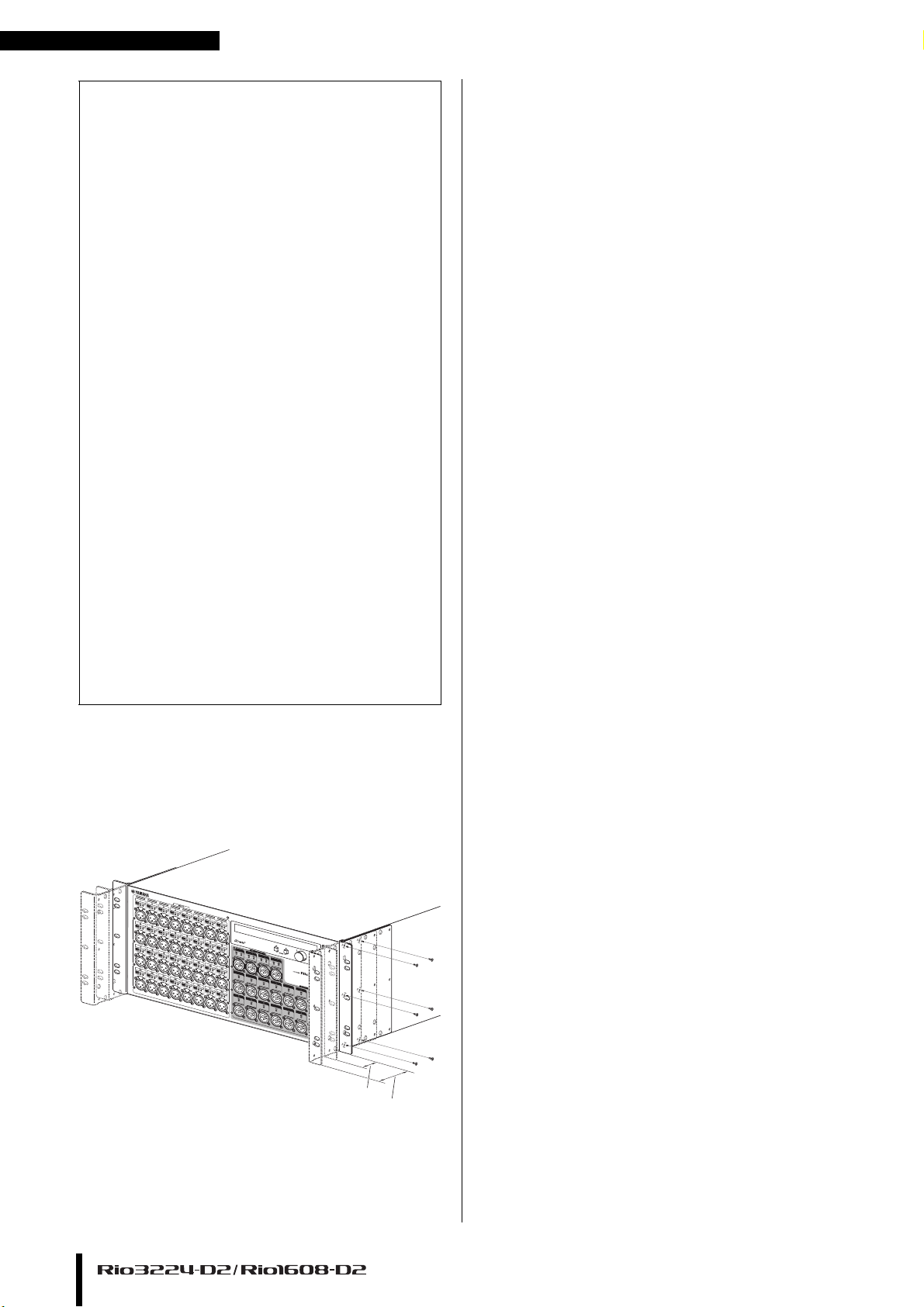
Recessed Installation
If you want to recess the front panel surface of the device
from the front edge of the rack, you can adjust the position
of the rack mount br acket s to rec ess the d evice by 50mm or
100mm, as shown in the illustration below.
About Dante
Dante is a network audio protocol developed by the
Audinate. Within a Giga-bit Ethernet (GbE), Dante
delivers multi-channel audio signals at various sampling
frequencies and bit rates, as well as device control signals.
Visit the Audinate website for more details on Dante.
http://www.audinate.com/
More information on Dante is also posted on the Yamaha
Pro Audio website:
https://www.yamaha.com/proaudio/
This product uses Dante Brooklyn2.
Refer to the Audinate website (English) for details on the
open‐source licenses for the particular software.
https://www.audinate.com/software-licensing
Caution when using a network switch
Please do not use the EEE function (*) of network switches
in a Dante network.
Although power management should be negotiated
automatically in switches that support EEE, some switches
do not perform the negotiation properly.
This may cause EEE to be enabled in Dante networks when
it is not appropriate, resulting in poor synchronization
performance and occasional dropouts.
Therefore we strongly recommend the following:
• When using a managed switch, turn off the EEE function
of all ports used by Dante. Do not use a switch that is
unable to turn off the EEE function.
• If using an unmanaged switch, do not use a switch that
supports the EEE function. Such switches are unable to
turn off the EEE function.
* EEE (Energy Efficient Ethernet) is a technology that reduces switch
power consumption during periods of low network traffic. It is also
known as Green Ethernet or IEEE802.3az.
In the same way, ra ck mount hardware can als o be attac hed
to the rear panel surface.
NOTE
When you install the brackets, use the same screws that
you just removed.
8
Owner’s Manual
Page 9
Controls and Functions
1 5
6
97
A
0
B
3
2 3 4
8
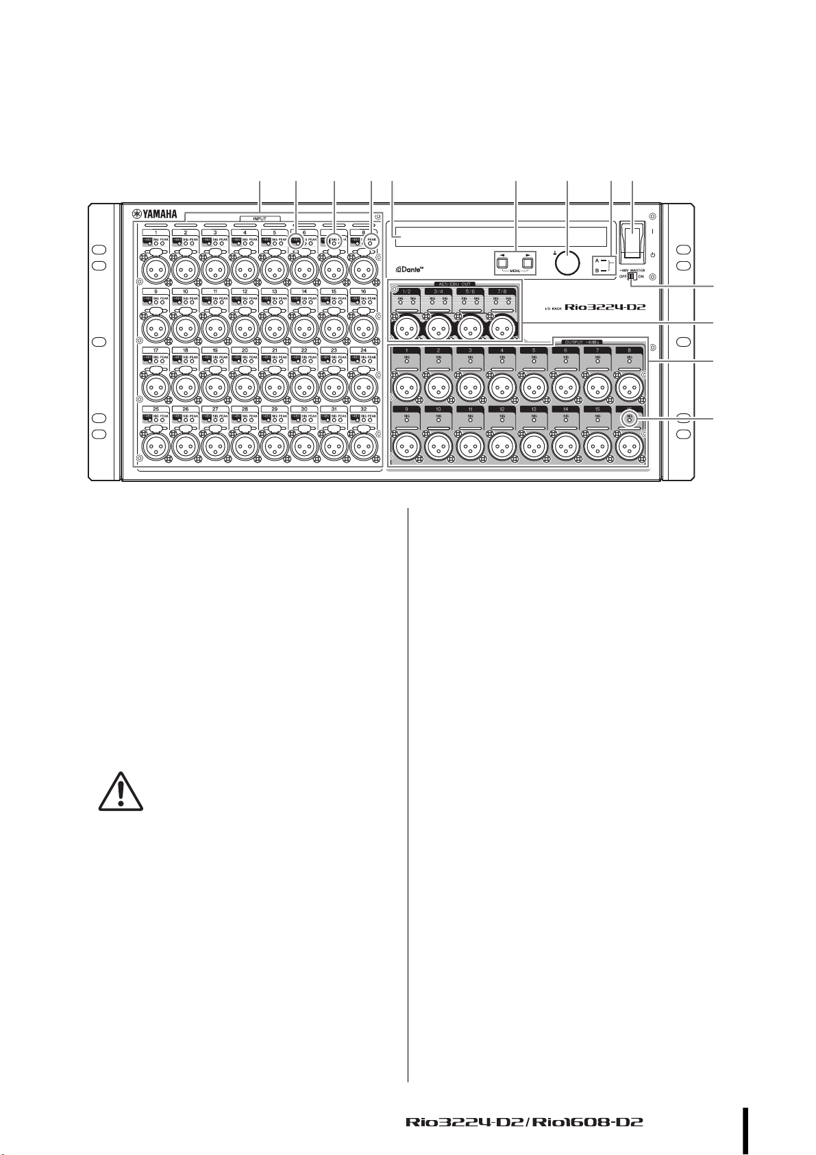
Front Panel
Controls and Functions
1 [INPUT] Connectors 1–32 {1–16}
These are the XLR-3-31 type analog balanced
connectors for the input channels. The input level
range is from –62 dBu to +10 dBu. +48V phantom
power can be supplied to devices that require it via the
input connectors.
2 [+48V] Indicators
These indicators light when +48V phantom power is
turned ON for the corresponding input channels.
On/off switching is controlled from this unit’s front
panel display, or from a compatible digital mixer. No
phantom power will be supplied, however, if the
[+48V MASTER] switch is OFF, even if phantom
power to individual channels is turned ON (the +48V
indicators will flash). If a serious error occurs in this
unit, the indicators of all channels will light or flash.
CAUTIONS:
• If phantom power is not required, you must turn OFF the
+48V MASTER switch or the phantom power setting.
• When turning phantom power ON, make sure that no
equipment other than phantom-powered devices such as
condenser microphones are connected to the
corresponding [INPUT] connectors. Applying phantom
power to a device that does not require phantom power can
damage the connected device.
• Do not connect or disconnect a device to an INPUT while
phantom power is applied. Doing so can damage the
connected device and/or the unit itself.
• To prevent possible damage to speakers, make sure that
power amplifiers and/or powered speakers are turned OFF
when switching phantom power ON or OFF. We also
recommend setting all digital mixing console output
controls to minimum when turning phantom power ON or
OFF. Sudden high level peaks caused by the switching
operation can damage equipment as well as the hearing of
those present.
3 [SIG] (Signal) Indicators
These indicators light green when the signal applied
to the corresponding channel reaches or exceeds
–40 dBFS.
If a serious error occurs in this unit, the indicators of
all channels will light or flash.
4 [PEAK] Indicators
These indicators light red when the signal level of the
corresponding channel reaches or exceeds –3 dBFS.
If a serious error occurs in this unit, the indicators of
all channels will light or flash.
5 Display
This shows information such as the parameter values
of each port’s head amp, or error and status
indications.
6 (DEC) button / (INC) button
Use these to move the cursor within the display.
7 Encoder with switch
By turning this you can edit a parameter value shown
in the display. By pressing the encoder you can select
or confirm a setting, or switch the display.
8 Power Indicator
Lights when AC power to the unit is ON.
Owner’s Manual
9
Page 10

Controls and Functions
9 Power Switch ( )
Turns power to the unit ON or OFF.
CAUTIONS:
Even when the power switch is turned off, electricity is still
flowing to the product at the minimum level. When you are
not using the product for a long time, make sure to unplug
the power cord from the wall AC outlet.
NOTE
Rapidly turning the unit on and off in succession can cause
it to malfunction. After turning the unit off, wait for about 6
seconds before turning it on again.
0 [+48V MASTER] Switch
This is the master switch for the unit’s +48V phantom
power supply.
If the [+48V MASTER] switch is off, no phantom
power will be supplied to the unit’s input connectors
even if the individual input phantom power settings
are ON. In this case, the [+48V] indicators will flash
on channels for which phantom power is turned ON.
A [AES/EBU OUT] Connectors 1/2–7/8
(Rio3224-D2 only)
These XLR-3-32 type balanced connectors deliver
AES/EBU format digital output from the unit’s
corresponding output channels. Each connector
outputs 2-channel digital audio.
B [OUTPUT +4 dBu] Connectors 1–16 {1–8}
These XLR-3-32 type balanced connectors deliver
analog output from the unit’s corresponding output
channels. Nominal output level is +4 dBu.
NOTICE:
If you cannot avoid connecting this unit’s balanced output
to an unbalanced device, you should match the ground
polarity of each unit, since differences in the ground
polarity may cause a device to malfunction.
For the cable used to connect an unbalanced device,
connect pin 3 COLD with pin 1 GND.
10
Owner’s Manual
Page 11
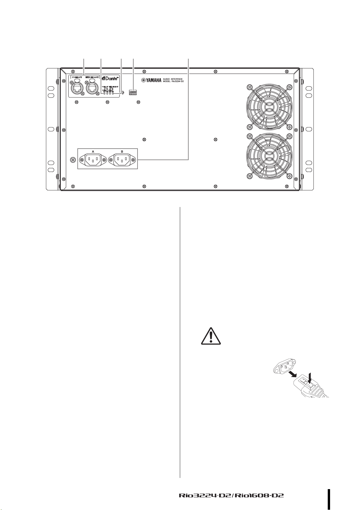
Rear Panel
DC
F
E G
Rear Panel
C [PRIMARY]/[SECONDARY] Connectors
These are etherCON (RJ45) ports can be connected to
other Dante devices such as a RIVAGE, CL, QL, or TF
series unit using Ethernet cables (CAT5e or better
recommended). If the SETUP menu SECONDARY
PORT parameter is set to DAISY CHAIN in the
display, the signal that is input from one port is
transmitted to the other port. Refer to “Daisy Chain
Network” in the “About Connections” section (see
page 25) for more information on daisy chain
connections.
If the SETUP menu SECONDARY PORT parameter
is set to REDUNDANT in the display, the
[PRIMARY] port is for the primary connection and
the [SECONDARY] port is for the secondary
(backup) connection. If the unit is unable to transmit
signals through the [PRIMARY] connector for some
reason (e.g., due to damage or accidental removal of
the cable, or a failed network switch), the
[SECONDARY] connector will automatically take
over the connection. Refer to “About Redundant
Networks” in the “About Connections” section (see
page 25) for more information on redundant
networks.
NOTE
• The use of Ethernet cables with Neutrik etherCON CAT5e
compatible RJ45 plugs is recommended. Standard RJ45
plugs can also be used.
• Use STP (shielded twisted pair) cable to prevent
electromagnetic interference. Make sure that the metal
parts of the plugs are electrically connected to the STP
cable shield by conductive tape or comparable means.
• Connect only Dante-compatible devices or
GbE-compatible devices (including a computer).
D [LINK/ACT] Indicators
These indicators show the communication status of
the [PRIMARY] and [SECONDARY] connectors.
They flash fast if the Ethernet cables are connected
properly.
E [1G] Indicators
These indicators light when the Dante network is
functioning as Giga-bit Ethernet.
F DIP switches
These are for expanding the functionality in the
future. At present, no functions are assigned to these
DIP switches.
G AC IN Connector
Connect the supplied AC power cord here. First,
connect the power cord to the device, then insert the
power cord plug into the AC outlet.
The supplied power cord features a special latching
mechanism (V-LOCK) to prevent the power cord
from being accidentally disconnected. Connect the
power cord by inserting the power cord fully until it is
locked.
CAUTION:
Be sure to turn the power off before connecting or
disconnecting the power cord.
Press the latch button on the
plug to disconnect the power
cord.
Owner’s Manual
11
Page 12

Display Operations
METER GAIN +48V ON HPF ON HPF F GC ON *1 SETUP
INFORMATION
METER
For the HPF ON menu
Upper line
Middle line
Lower line
Display Operations
Operation Flow
On the Rio3224-D2/Rio1608-D2, you can use the front panel display, (DEC) button, (INC) button, and the encoder with
switch to set the various parameters that are shown in each menu.
• The menu name is shown at the left edge of the display.
• The parameters of each menu are shown in the center of the display.
• The status of the unit is shown by icons at the right edge of the display.
Menu structure
The menu shown at the left edge of the display has the following structure. Select a menu item by pressing the (DEC) button
and (INC) button appropriately.
*1 GC= Gain Compensation
Selecting menu items
You can use any of the following methods to select the next-lower menu.
• Press the (DEC) button and (INC) button simultaneously.
• While holding down the (DEC) button for 1.5 seconds or longer, press the (INC) button.
You can use any of the following methods to select the next-higher menu.
• Hold down the (DEC) button and (INC) button simultaneously for 1.5 seconds or longer.
• While holding down the (INC) button for 1.5 seconds or longer, press the (DEC) button.
About the parameter display
The parameter values of each port are shown divided into three areas
(upper line, middle line, lower line).
12
Owner’s Manual
Page 13

Selecting ports
For the METER menu
You can select ports by pressing the (DEC) button or (INC) button. When you do so, the selected port’s LEDs
(+48V/SIG/PEAK for Input, or SIG for Output) is lit for one second. The corresponding location is indicated by a white
frame cursor. The white frame cursor disappears when 10 seconds have elapsed without any front panel operation being
performed. When you once again press the (DEC) button or (INC) button, the white frame cursor appears at the
previous port position.
By long-pressing the (DEC) button or (INC) button, you can jump to the first of every eight ports.
For the GAIN, +48V ON, HPF ON, HPF F, and GC ON menus
You can select the input port or status by pressing the (DEC) button or (INC) button. Output ports cannot be
selected. The parameter display area of the selected input port is highlighted; at the same time, the selected input port’s
LEDs (+48V/SIG/PEAK) are lit for one second. The highlighted indication disappears when 10 seconds have elapsed
without any front panel operation being performed. When you once again press the (DEC) button or (INC) button,
the white frame cursor appears at the previous port position.
By long-pressing the (DEC) button or (INC) button, you can jump to the first of every eight ports.
About port names
Selecting ports
For the METER menu
The port name shown in the upper middle of the display can be edited from Dante Controller. A name of up to 31
characters can be specified for each input or output port.
For the GAIN, +48V ON, HPF ON, HPF F, and GC ON menus
The port name shown in the upper line can be edited from Dante Controller. A name of up to 31 characters can be
specified for each input or output port. However, since a maximum of five characters of the port name can be shown in
this menu, “..” is shown following the fourth character if six or more characters have been specified.
Owner’s Manual
13
Page 14

Display Operations
When there is an input or output of –3 dBFS or greater
When there is an input or output greater than –18 dBFS and not exceeding –3 dBFS
When there is an input or output greater than –60 dBFS and not exceeding –18 dBFS
NOTE
PEAK HOLD is always on, but you can clear the PEAK held for each port by pressing
the encoder switch.
METER menu
Level meters for all input ports are shown at the left, and level meters for all output ports are shown at the right.
The upper part of the display shows icons that indicate the +48V ON, HPF ON, and GC ON status of the selected port.
Rio3224-D2
Rio1608-D2
Viewing the meters
Head amp (HA) gain value settings
By turning the encoder with switch, you can adjust the HA gain value of the selected port. This can be adjusted in the
range of –6 dB to +66 dB, in 1 dB units.
14
Owner’s Manual
Page 15

GAIN menu
GAIN menu
This shows the HA parameters of all input ports (upper line: port name, middle line: GC ON status and compensation gain
value, lower line: HA gain value), the port name of all output ports, and the status of the unit itself. In this menu you can set
the HA gain value of each input port.
Rio3224-D2 input ports
Rio3224-D2 output ports/status (upper right)
Rio1608-D2 input ports (left half) / output ports (lower right) / status (upper right)
Head amp (HA) gain value settings
By turning the encoder with switch, you can adjust the HA gain value of the selected port. This can be adjusted in the
range of –6 dB to +66 dB, in 1 dB units.
+48V ON menu
This shows the +48V parameters of all input ports (upper line: port name, lower line: +48V ON), the port name of all output
ports, and the status of the unit itself. In this menu, you can turn on/off the phantom power (+48V) of each input port.
Rio3224-D2 input ports
Rio3224-D2 output ports/status (upper right)
Rio1608-D2 input ports (left half) / output ports (lower right) / status (upper right)
Phantom power (+48V) settings
By turning the encoder with switch, you can turn on/off the phantom power (+48V) of the selected port. If the value is
changed, the display area of the currently selected parameter flashes. When you press the encoder, the setting is actually
specified, and the flashing stops. If you move the cursor while the parameter display area is flashing, the change is
discarded and the flashing also stops. In the same way, if you switch the menu selection while the parameter display area
is flashing, the change is discarded.
Owner’s Manual
15
Page 16

Display Operations
HPF ON menu
This shows the HPF parameters of all input ports (upper line: port name, middle line: HPF cutoff frequency, lower line: HPF
ON status), the port name of all output ports, and the status of the unit itself. In this menu you can set the HPF on/off status
of each input port.
Rio3224-D2 input ports
Rio3224-D2 output ports/status (upper right)
Rio1608-D2 input ports (left half) / output ports (lower right) / status (upper right)
HPF on/off settings
By turning the encoder with switch, you can turn on/off the HPF of the selected port. If the value is changed, the display
area of the currently selected parameter flashes. When you press the encoder, the setting is actually specified, and the
flashing stops. If you move the cursor while the parameter display area is flashing, the change is discarded and the
flashing also stops. In the same way, if you switch the menu selection while the parameter display area is flashing, the
change is discarded.
HPF F menu
This shows the HPF parameters of all input ports (upper line: port name, middle line: HPF ON status, lower line: HPF cutoff
frequency), the port name of all output ports, and the status of the unit itself. In this menu you can set the HPF cutoff
frequency of each input port.
Rio3224-D2 input ports
Rio3224-D2 output ports/status (upper right)
Rio1608-D2 input ports (left half) / output ports (lower right) / status (upper right)
HPF cutoff frequency settings
By turning t he encoder with switch, you can change the HPF cutoff frequenc y of the selected port in th e range of 20.0 Hz
to 600.0 Hz.
16
Owner’s Manual
Page 17

GC (Gain Compensation) ON menu
GC (Gain Compensation) ON menu
This shows the GC parameters of all input ports (upper line: port name, middle line: compensation gain value if GC is ON;
HA gain value if GC is OFF, lower line: GC ON status), the port name of all output ports, and the status of the unit itself. In
this menu you can set the GC on/off status of each input port.
Rio3224-D2 input ports
Rio3224-D2 output ports/status (upper right)
Rio1608-D2 input ports (left half) / output ports (lower right) / status (upper right)
GC on/off settings
By turning the encoder with switch, you can turn on/off the GC of the selected port. If the value is changed, the display
area of the currently selected parameter flashes. When you press the encoder, the setting is actually specified, and the
flashing stops. If you move the cursor while the parameter display area is flashing, the change is discarded and the
flashing also stops. In the same way, if you switch the menu selection while the parameter display area is flashing, the
change is discarded.
About the status indication
The upper line of the status area shown in each menu shows the Dante device label of the unit; the lower line shows an
ERROR/INFORMATION icon and corresponding message only if an ERROR/INFORMATION state occurs.
Rio3224-D2 output ports/status (upper right)
Rio1608-D2 input ports (left half) / output ports (lower right) / status (upper right)
NOTE
If multiple ERROR/INFORMATION states occur, the highest-priority state is shown.
The device label can be specified from Dante Controller. Assign the device label as follows.
• Specify the first five characters as Y0##- (## is the UNIT ID). Even if you omit this, it is forcibly corrected
to Y0##-.
• A maximum of 31 characters total
When you move the cursor to the status indication and press the encoder with switch, the unit’s version, SYSTEM/SYNC
message ID, and ERROR state (SYSTEM/SYNC message) are shown as depicted in the following illustration. Press the
encoder once again to return to the menu screen. For a list of the SYSTEM/SYNC messages, refer to the “Troubleshooting”
section’s table “SYSTEM/SYNC Messages” (page 29).
Owner’s Manual
17
Page 18

Display Operations
HA GAIN –6 dB
+48V OFF
HPF OFF
HPF FREQ 80.0 Hz
GAIN COMPENSATION OFF
COMPENSATION GAIN –6 dB
SETUP menu
This shows the current values for various setup parameters of this unit.
Selecting a setup item
You can select setup items by pressing the (DEC) button or (INC) button. The parameter value of the selected item
is highlighted. The highlighted indication disappears when 10 seconds have elapsed without any front panel operation
being performed. You can switch screens by long-pressing the (DEC) button or (INC) button.
Setting a parameter value
By turning the encoder with switch, you can select the parameter value of the selected item. If the value is changed, the
display area of the currently selected parameter flashes. When you press the encoder, the setting is actually specified, and
the flashing stops. If you move the cursor while the parameter display area is flashing, the change is discarded and the
flashing also stops. In the same way, if you switch the menu selection while the parameter display area is flashing, the
change is discarded.
Table of parameters
The following table shows the items that can be selected, the description of the parameters, and the values that can be
specified (* is the default value).
Item/parameter Description Values
UNIT ID Specifies the ID of the unit. Y000(0)–Y07F(127)
START UP MODE Selects the HA parameter settings at start-up. This setting is applied the
next time the unit starts up.
If you plan to connect an Rio-native device, such as a CL series product,
set the switches to [REFRESH]. The Rio will not input or output audio
until the connected Rio-native device transmits its settings to the Rio, so
that the Rio will not output audio accidentally.
REFRESH:
Initializes a portion of the internal memory when starting up.
However, MUTE is ON.
Y001*
REFRESH*,
RESUME,
REFRESH w/o MUTE
18
RESUME:
Starts up in the state prior to the most recent power-off.
However, MUTE is OFF.
REFRESH w/o MUTE
Initializes a portion of the internal memory when starting up. The
initial values are the same as for REFRESH.
However, MUTE is OFF.
Owner’s Manual
Page 19

Item/parameter Description Values
SECONDARY PORT Specifies the operating mode of the Dante secondary port. DAISY CHAIN*,
REDUNDANT
FAN SPEED Specifies the rotation speed of the fan. LOW*,
HIGH
NETWORK MODE Selects the IP address setting mode. This IP address is used when
remotely controlling the unit from a computer, or when updating the
firmware. This is different than the IP address for Dante.
IP ADDRESS Specifies the IP address.
(when STATIC IP is specified)
SUBNET MASK Specifies the SUBNET MASK.
(when STATIC IP is specified)
DEFAULT GW Specifies the DEFAULT GATEWAY.
(when STATIC IP is specified)
DIMMER Specifies the time after which the organic EL display goes dark when
the unit has not been operated for a time.
In order to extend the life of the organic EL display, it is designed to go
dark after the specified time.
ERROR MESSAGES Specifies whether an error message is shown without dimming the
display when an error/alert occurs.
BRIGHTNESS Specifies the brightness of the organic EL display.
This can also be adjusted by long-pressing the (DEC) button and
(INC) button for 1.5 seconds or longer, and turning the encoder with
switch.
INITIALIZE When you select the memory that you want to initialize, and then press
the encoder with switch, a confirmation appears; press [OK] to execute
initialization.
AUTO*,
STATIC IP
0.0.0.0
In the case of AUTO, the
current value is shown*
0.0.0.0
In the case of AUTO, the
current value is shown*
0.0.0.0
In the case of AUTO, the
current value is shown*
10sec,
30sec,
1min,
2min,
3min*,
5min
LIGHT OFF*,
KEEP MESSAGES
5%–100%
(adjustable in 5% steps),
70%*
FACTORY PRESET*,
HA PARAMETERS,
DANTE SETTINGS
SETUP menu
IP ADDRESS, SUBNET MASK, and DEFAULT GW can be edited only if NETWORK MODE is set to STATIC IP. If it is
set to AUTO, the current settings can only be displayed, and not edited.
If Dante Device Lock has been enabled from Dante Controller, it is not possible to change the Dante-related settings
UNIT ID or SECONDARY PORT. If you want to change these settings, use Dante Controller to defeat Dante Device
Lock.
Owner’s Manual
19
Page 20

Display Operations
Status bar
The status bar at the right edge of the display shows icons to indicate the status of the Rio3224-D2 unit or Rio1608-D2 unit.
Icon
Six types of icons are shown.
ERROR INFORMATION MUTE PANEL LOCKDAISY CHAIN
HA READ ONLY
The displayed position depends on the icon.
Shows the ERROR icon or the INFORMATION icon .
Upper line
Middle line
Lower line
If both ERROR and INFORMATION have occurred, the ERROR icon takes priority and is shown.
If neither ERROR nor INFORMATION has occurred, nothing is displayed.
If ERROR or INFORMATION have occurred, the content is shown in the second line of the status display area
within each HA screen. For an explanation of the content, refer to “Messages” (page28).
Shows the MUTE icon if muted (all ports together).
If the SECONDARY PORT parameter is set to DAISY CHAIN, the DAISY CHAIN icon is shown.
If muted (all ports together) and in addition the SECONDARY PORT parameter is set to DAISY CHAIN, the
MUTE icon takes priority and is shown.
If mute is cleared (all ports together) and in addition the SECONDARY PORT parameter is set to
REDUNDANT, nothing is displayed.
Shows the LOCK status.
If panel lock is enabled, the PANEL LOCK icon is shown.
If HA Read Only is specified, the HA READ ONLY icon is shown to indicate read-only.
If panel lock is enabled and HA Read Only is specified, the PANEL LOCK icon takes priority and is shown.
If panel lock is not enabled, or if HA Read Only is not specified, nothing is displayed.
About HA Read Only
When operating a system containing a Rio2-native device such as a RIVAGE, CL, QL, or TF series unit, this function
allows the HA parameters to be changed only from the Rio2-native device or from R Remote.
The HA parameters will be read-only, and it will not be possible to operate the HA parameters or change the HA Read
Only setting from this unit.
When this unit starts up, this setting is always OFF.
This function is included in the setting items of a Rio2-native device, and is set when this unit synchronizes with the
Rio2-native device. If the connection between this unit and the Rio2-native device is broken while HA Read Only is ON,
the HA Read Only setting is maintained.
NOTE
The settings in the SETUP menu of this device can be changed even when HA Read Only is ON.
In order to turn HA Read Only OFF, you must perform an operation from the Rio2-native device, or power-cycle this unit.
20
Owner’s Manual
Page 21

INFORMATION menu
INFORMATION menu
This shows various information about this unit.
When the INFORMATION menu is selected
Selecting items and viewing detailed information
You can select items by pressing the (DEC) button or (INC) button. The highlighted indication disappears when
10 seconds have elapsed without any front panel operation being performed.
When you press the encoder with switch, detailed information for the selected item is shown. By turning the encoder,
you can scroll the displayed content up or down.
List of items
The following table provides a description of the items that can be selected and the values that can be set.
Item Description
SYSTEM Shows the version of this unit, the SYSTEM/SYNC status, and the ERROR occurrence status.
DANTE Shows information for Dante-related settings.
LOG Shows the event/error history of this unit.
REPORT Shows basic information and historical information for this unit.
SYSTEM information display example
*) If this unit’s Dante Device Lock is enabled, or if AES67 mode is enabled,
*) By turning the encoder, you can scroll the displayed content up or down.
*) By turning the encoder, you can scroll the displayed content up or down.
DANTE information display example
the respective icon is shown in the upper right.
LOG information display example
REPORT information display example
Owner’s Manual
21
Page 22

Display Operations
Support for Dante Domain Manager (V1.10 or later)
NOTE
Firmware V1.10 or later is required for Rio3224-D2/Rio1608-D2 to enroll a domain with DDM.
INFORMATION – DANTE screen
When enrolling a domain:
The DDM indicator appears at the top of right side of the DANTE screen.
The R/W indicator or the R/O indicator also appears, depending on the LOCAL CONTROLLER ACCESS setting for the
DDM server.
* LOCAL CONTROLLER ACCESS = Read Write
* LOCAL CONTROLLER ACCESS = Read Only
When the local access is set to “Read Only,” changing the DANTE settings (UNIT ID, SECONDARY PORT) on the
Rio3224-D2/Rio1608-D2 unit will result in the following pop-up message.
When a DDM domain is enrolled, unregistering the domain will result in the DISC indicator appearing at the top right
side of the screen. In addition, when a DDM domain is enrolled without connecting to the DDM server, the DISC
indicator also appears.
22
Owner’s Manual
Page 23

INFORMATION – REPORT screen
Enrolling a domain
* Local Access = Read Only, Remote Access = None
No DDM server
1 DDM_CONNECT_STATE
Displays the connection status to the DDM server in the network.
• CONNECTED: The unit has been connected to the DDM server in the network.
• DISCONNECTED: There is no DDM server in the network.
2 DDM_DOMAIN_KIND
Displays the enrolling status for the DDM domain.
•DOMAIN: DDM domain is enrolled
• UNMANAGED: DDM domain is not enrolled
Support for Dante Domain Manager (V1.10 or later)
3 DDM_DOMAIN_UUID
Displays the UUID of an applicable domain when enrolling the DDM domain.
When the unit has not enrolled a domain, FF–FF–FF–FF–FF–FF–FF–FF–FF–FF–FF–FF–FF–FF–FF–FF is displayed.
4 DDM_LOCAL_ACCESS
Displays the accessing status of the Dante setup (including the DANTE PATCH settings) of the unit.
• READ_WRITE: Editing is available
• READ_ONLY: Editing is disabled
5 DDM_REMOTE_ACCESS
Displays the status of Dante setup accessing the external Dante device.
• OPERATOR: Editing is available
(however, operating from the Rio3224-D2/Rio1608-D2 unit is not available)
• GUEST: Reading is available, editing is disabled
• NONE: Reading and editing are disabled
Owner’s Manual
23
Page 24

Display Operations
Other functions
Initializing to the factory-set state
If you turn on the power while holding down both the (DEC) button and (INC) button, you can enter a mode that
returns this unit’s settings to their factory-set state. This is the same as if you use the SETUP menu to select INITIALIZE
→ FACTORY PRESET.
Initializing the HA parameters
If you turn on the power while holding down only the (DEC) button, you will enter a mode that returns the HA
parameter values to their factory-set state.
is is the same as if you use the SETUP menu to select INITIALIZE → HA PARAMETERS.
Initializing the Dante parameters
If you turn on the power while holding down only the (INC) button, you will enter a mode that returns the Dante
parameter values to their factory-set state. is is the same as if you use the SETUP menu to select INITIALIZE →
DANTE SETTINGS.
Factory-set initial values
The following table shows the factory-set initial values.
Parameter Initial value
SETUP UNIT ID Y001
START UP MODE REFRESH
SECONDARY PORT DAISY CHAIN
FAN SPEED LOW
NETWORK MODE AUTO
IP ADDRESS (determined by DHCP or link local)
SUBNET MASK (determined by DHCP or link local)
DEFAULT GW (determined by DHCP or link local)
DIMMER 3 min
ERROR MESSAGE LIGHT OFF
BRIGHTNESS 70%
HA Parameters HA GAIN –6 dB
+48V Off
HPF Off, 80.0 Hz
GAIN COMPENSATION Off, –6 dB
DANTE Settings Sample Rate 96 kHz (slave), Pull-up/down = None
Latency 1.0 ms
Encoding PCM 24 bit
Dante Redundancy Switched (depends on the setting of SETUP SECONDARY PORT)
IP Address Auto
Device Label Y001-Yamaha-Rio3224-D2-nnnnnn *1
Y001-Yamaha-Rio1608-D2-nnnnnn *1
Channel Label <channel number>
AES67 Mode Disabled
Device Lock Unlock
*1 nnnnnn is the lowest six digits of the Dante Primary MAC Address
Panel lock
While this unit is operating, you can put it in the panel lock state by simultaneously holding down the (DEC) button,
(INC) button, and the encoder with switch for approximately three seconds. This state is maintained even if the unit
is power-cycled. To defeat the panel lock state, simultaneously hold down the (DEC) button, (INC) button, and the
encoder with switch once again for approximately three seconds.
Brightness adjustment
While this unit is operating, simultaneously hold down the (DEC) button and (INC) button for at least 1.5 seconds,
and turn the encoder with switch to adjust the brightness of the display (BRIGHTNESS).
24
Owner’s Manual
Page 25

About Connections
Rio3224-D2 (UNIT ID: Y001)
Rio3224-D2 (UNIT ID: Y002)
SECONDARY
PRIMARY
PRIMARY
CSD-R7
HY144-D
Network switch A
Network switch B
Primary Dante
Secondary Dante
About Connections
There are two ways to connect the Rio to a Dante network.
NOTE
A daisy chain connection is suitable for a simple system
with a small number of devices.
Use a star network if a large number of devices are
connected.
Daisy Chain Network
A daisy chain is a wiring scheme in which multiple devices
are connected together in sequence. In this way,
networking is simple and requires no network switches.
If you connect a large number of devices, you must set a
higher latency value to avoid skipping audio that could be
caused by an increased delay in signal transfer among the
devices. Also, if a connection is broken in a daisy chain
network, the signal flow is interrupted at that point and no
signal will be transferred beyond that point.
Star Network
In a star network, each device is connected to a central
network switch. Using a GbE-compatible network switch
enables you to configure a wide-band, large-scale network.
We recommend a network switch that features various
functions to control and monitor the network (such as Qos,
the ability to assign priority to data flows - e.g., clock
synchronization or audio transmission on certain data
circuits.)
With this topology, it is common to configure a redundant
network so that an unexpected network problem will not
affect any audio or otherwise stable communications.
About Redundant Networks
A redundant network consists of two circuits, a primary
circuit and a secondary circuit. Normally, the network
operates on the primary circuit. However, if the primary
connection is broken, the secondary circuit will
automatically take over communications. Therefore, using
a redundant network with a star topology would increase
communication stability relative to a daisy chain network.
HY144-D
PRIMARY
SECONDARY
PRIMARY
CSD-R7
Rio3224-D2 (UNIT ID: Y001)
SECONDARY
Rio3224-D2 (UNIT ID: Y002)
SECONDARYPRIMARY
Owner’s Manual
25
Page 26

Head Amp Control
Dante Network Settings and Audio Routing
The audio inputs and outputs of multiple Dante devices can
be freely routed within a Dante network. This means that
you need to make settings that specify the destination to
which each channel’s signal will be sent.
Use Dante Controller to specify the Dante network and
audio routing settings.
Dante Controller can be downloaded from the following
website.
https://www.yamaha.com/proaudio/
For details on Dante Controller, refer to the Dante
Controller owner’s manual on the same website.
Head Amp Control
The Rio head amplifiers can be remotely controlled from a
host device, such as a compatible Yamaha digital mixing
console.
Control from an Rio2-native Device
The Rio head amplifiers can be controlled remotely from
an Rio2-native device such as a RIVAGE, CL, QL, or TF
series product.
The connected Rio2-native device displays the model
name and UNIT ID number of the corresponding Rio unit
to be controlled.
If you plan to connect to a Rio2-native device to monitor
and control the head amplifiers, refer to the owner’s
manual for the corresponding device.
Head Amplifier Parameters That Can be Monitored and Controlled
Parameter Description
+48V
HA GAIN
HPF
HPF FREQ
METER
(Rio2-native device only)
+48V Master SW
Gain Compensation
(Rio2-native device only)
Turns +48V phantom power ON or
OFF for each channel.
Adjusts gain from –6 dB to 66 dB in
1-dB increments.
Turns the high-pass filter ON or
OFF.
Adjusts the cutoff frequency of the
high-pass filter (12 dB/Oct.) from
20 Hz to 600 Hz in 60 steps.
Displays a level meter for each
input channel.
Displays the [+48V MASTER]
switch ON/OFF status of the +48V
phantom power supply.
Turns the Gain Compensation ON
or OFF.
26
Owner’s Manual
Page 27

Troubleshooting
Troubleshooting
Symptom Cause Possible Solution
The power won’t turn on.
The power indicator doesn’t light.
The unit is not receiving an input
signal.
The input level is too low. A condenser microphone is connected. Turn the [+48V MASTER] switch ON.
No sound is heard. The cables are not connected properly. Connect the cables properly.
The head amp cannot be controlled. The Rio has not been mounted on the
Adjusting the internal head amp gain
does not change the audio level.
The Rio cannot be found in Dante
Controller.
The Rio cannot be found in R Remote. The UNIT ID setting conflicts with
The Rio cannot be found in R Remote. The IP address setting is incorrect.
The power LED is lit, but nothing
appears in the display.
Button operations and encoder
operations do not work.
The power cable is connected
improperly.
The [POWER] switch is not turned ON. Turn the [POWER] switch ON. If the power still will not
The input cables are not connected
properly.
The source device is not delivering an
appropriate signal.
The internal head amplifier gain is not
set to an appropriate level.
The SETUP menu’s START UP MODE
setting is REFRESH, but the Rio2-native
device has not started up.
The internal head amplifier gain is not
set to an appropriate level.
The SETUP menu’s START UP MODE
setting is REFRESH, but the Rio2-native
device has not started up.
Output is muted. Unmute the output on the Rio2-native device.
RACK of the Rio2-native device.
The Gain Compensation function is
turned on.
An incorrect value is assigned to the IP
address for Dante.
another R series unit.
Alternatively, the network is connected
wrongly.
A malfunction may have occurred. Contact a Yamaha service center.
Panel lock is enabled. Defeat panel lock.
Connect the power cable properly (see page 11).
come on, refer the problem to your Yamaha dealer.
Connect the cables properly.
Output a signal from the source device and make sure
that the SIG indicators on the appropriate channels
will light.
Set the internal head amplifier gain to an appropriate
level.
Start the Rio2-native device to send the setting to the
Rio.
Turn phantom power for the corresponding channel(s)
ON.
Set the internal head amplifier gain to an appropriate
level.
Start the Rio2-native device to send the setting to the
Rio.
Mount the Rio on the RACK of the Rio2-native device.
If you are not using the Gain Compensation function,
turn it off.
Initialize the Rio.
Set each UNIT ID uniquely.
Re-check the network settings. Check whether they
are set to the same subnet. If the SECONDARY
PORT parameter is set to REDUNDANT, check
whether the unit is connected to the [PRIMARY] port.
To defeat panel lock, simultaneously hold down the
(DEC) button, (INC) button, and the encoder with
switch for approximately three seconds.
Troubleshooting
The Yamaha Pro Audio site provides a FAQ (frequently asked questions and answers).
https://www.yamaha.com/proaudio/
Owner’s Manual
27
Page 28

Troubleshooting
Messages
The front panel display of the Rio3224-D2/Rio1608-D2 shows various messages such as errors, alerts, warnings, information,
and confirmations.
Error Messages
Message Description Possible Solution
SYSTEM DOWN - PLEASE CONTACT
YAMAHA SERVICE
DANTE MODULE ERROR A problem was detected in the Dante module. Restart this unit.
ILLEGAL MAC ADDRESS - PLEASE
CONTACT YAMAYA SERVICE
FAN HAS MALFUNCTIONED - PLEASE
CONTACT YAMAHA SERVICE
MEMORY ERROR Failed to read from non-volatile memory. Information that was saved during the
Alert Messages
A system error was detected at the previous
execution.
There is no valid Mac Address. Contact a Yamaha service center.
The fan is not working correctly. Contact a Yamaha service center.
Contact a Yamaha service center.
previous operation was lost, so this
information must be reset.
Message Description Possible Solution
FIRMWARE VERSION MISMATCH BETWEEN YAMAHA AND DANTE.
PLEASE UPDATE FIRMWARE.
FIRMWARE VERSION MISMATCH BETWEEN DEVICE AND CONSOLE.
PLEASE UPDATE FIRMWARE.
POWER SUPPLY "A" ("B") FAILED IF A RECURRING ERROR, PLEASE
CONTACT YAMAHA SERVICE
GIGABIT NETWORK LINK FAILED SWITCHED TO 100Mbps (or 10Mbps)
DANTE PRIMARY NETWORK LOST SWITCHED TO SECONDARY PORT
The combination of this unit’s firmware and
the Dante firmware is incorrect.
The combination of the Rio2’s firmware and
the console’s firmware is incorrect.
The supply of power to either power supply A
or B has been interrupted.
Dante is not operating at 1 Gbps. Check the link status. Try plugging into a
When connected via a redundant network, a
problem occurred with the primary
connection, and communication has switched
to the secondary connection.
Match them to compatible versions.
Match them to compatible versions.
Check that the power supply cable is
connected. If checking does not resolve the
problem, contact a Yamaha service center.
different network switch or a different port.
Alternatively, try using a different network
cable.
Check the connections of the Dante primary
network.
Warning Messages
Message Description Possible Solution
DANTE AUDIO RESOURCE
OVERFLOW
WRONG WORD CLOCK A problem was detected in the word clock. Check the Word Clock setting.
DANTE PORTS HAVE NO NETWORK
CONNECTION
DANTE CONNECTION ERROR A problem was detected in the Dante
ERROR OCCURRED AT DANTE
SECONDARY PORT
DANTE DEVICE LOCK ENABLED You may have attempted to change a DANTE
The number of Dante flows has exceeded the
limit.
Nothing is connected to the Dante port. Check the Dante connection.
connection.
The Dante secondary port is not functioning. Check the Dante connection.
setting such as this unit’s UNIT ID or
SECONDARY PORT while Dante Device Lock
was enabled.
Re-configure the Dante audio routing, for
example by eliminating unneeded routings, or
by using multicast rather than unicast to
improve the efficiency.
Check the Dante connection.
Use Dante Controller to defeat Dante Device
Lock.
28
Owner’s Manual
Page 29

Information Messages
Message Description
FACTORY INITIALIZE IN PROGRESS Started initializing to the factory-set state.
FACTORY INITIALIZE COMPLETED Finished initializing to the factory-set state.
HA MEMORY INITIALIZE IN PROGRESS Started initializing the HA parameters.
HA MEMORY INITIALIZE COMPLETED Finished initializing the HA parameters.
DANTE INTIALIZE IN PROGRESS Started initializing the Dante settings.
DANTE INITIALIZE COMPLETED Finished initializing the Dante settings.
FRONT PANEL LOCKED Started panel lock.
FRONT PANEL LOCKED.
TO UNLOCK - PRESS ALL BUTTONS FOR 3 SECONDS
FRONT PANEL UNLOCKED Panel lock was disabled.
Panel lock is enabled.
Confirmation Messages
Message Description
ARE YOU SURE YOU WANT TO INITIALIZE?
- FACTORY PRESET -
ARE YOU SURE YOU WANT TO INITIALIZE?
- HA PARAMETERS -
ARE YOU SURE YOU WANT TO INITIALIZE?
- DANTE SETTINGS -
Start initializing to the factory-set state?
Start initializing the HA parameters?
Start initializing the Dante settings?
Messages
SYSTEM Messages
Message ID * Description Possible Solution
NORMAL Starting up normally – – –
DANTE MODULE ERROR! E00-03 An error has occurred in the Dante module. The device has malfunctioned; please contact
a Yamaha service center.
ILLEGAL MAC ADDRESS! E00-04 Because the MAC Address setting has been
damaged, communication is not possible.
UNIT FAN HAS
MALFUNCTIONED!
MEMORY ERROR! E00-07 Because the internal memory has been lost,
VERSION MISMATCH! E00-10 The combination of this unit’s firmware and
DANTE AUDIO RESOURCE
OVERFLOW!
POWER SUPPLY FAILED! E00-13 The supply of power to either power supply A
* If the ID is blank, the message is shown. Otherwise, the ID is shown.
E00-06 The cooling fan has stopped. Check whether a foreign object might be
all data was initialized.
the Dante firmware is incorrect.
The combination of this unit’s firmware and
the Rio2-native device’s firmware is incorrect.
E00-11 The number of Dante flows has exceeded the
limit.
or B has been interrupted.
The device has malfunctioned; please contact
a Yamaha service center.
caught in the fan. If this does not solve the
problem, contact a Yamaha service center.
If you are using the unit with the START UP
MODE parameter set to RESUME, and
power-cycling the unit does not solve the
problem, please contact a Yamaha service
center.
Match them to compatible versions.
Re-configure the Dante audio routing, for
example by eliminating unneeded routings, or
by using multicast rather than unicast to
improve the efficiency.
Check that the power supply cable is
connected. If checking does not resolve the
problem, contact a Yamaha service center.
Owner’s Manual
29
Page 30

Troubleshooting
SYNC Messages
Message ID * Description Possible Solution
NORMAL Operating normally – – –
SYNCHRONIZATION Currently processing synchronization within
the Dante network.
WRONG WORD CLOCK! E01-03 The word clock setting is incorrect. On the Rio2-native device or in Dante
DANTE PORT DOES NOT
HAVE CONNECTION!
DANTE CONNECTION
ERROR!
DANTE IS NOT WORKING
BY G IGA BIT!
DANTE IS WORKING AT
SECONDARY!
ERROR OCCURRED AT
SECONDARY PORT!
DANTE WORD CLOCK
MASTER
DANTE IS NOT WORKING
BY G IGA BIT!
DANTE IS WORKING AT
SECONDARY!
ERROR OCCURRED AT
SECONDARY PORT!
E01-04 The Dante network is not connected. Check whether an Ethernet cable might be
E01-05 Other Dante devices cannot be found
because the Dante network connections are
incorrect.
E01-06 A device that does not support gigabit
Ethernet is connected.
E01-07 In the case of a redundant network,
communication is occurring via the
[SECONDARY] port.
E01-08 In the case of a redundant network, a problem
has occurred in the circuit that is connected to
the [SECONDARY] port.
Functioning correctly as the word clock
master.
E01-10 Functioning correctly as the word clock
master.
A device that does not support gigabit
Ethernet is connected.
E01-11 Functioning correctly as the word clock
master.
In the case of a redundant network,
communication is occurring via the
[SECONDARY] port.
E01-12 Functioning correctly as the word clock
master.
In the case of a redundant network, a problem
has occurred in the circuit that is connected to
the [SECONDARY] port.
Wait until startup or synchronization is
completed. It may take up to 45 seconds for
this to be completed.
Controller, set the clock master and the
sampling frequency correctly.
disconnected or broken.
Check whether the Ethernet cable
connections are correct.
If you are conveying audio via Dante, use
devices that support gigabit Ethernet.
Check the circuit that is connected to the
[PRIMARY] port.
Check the circuit that is connected to the
[SECONDARY] port.
This indicates that the device is the word clock
master.
This indicates that the device is the word clock
master.
If you are conveying audio via Dante, use
devices that support gigabit Ethernet.
This indicates that the device is the word clock
master.
Check the circuit that is connected to the
[PRIMARY] port.
This indicates that the device is the word clock
master.
Check the circuit that is connected to the
[SECONDARY] port.
* If the ID is blank, the message is shown. Otherwise, the ID is shown.
30
Owner’s Manual
Page 31

Specifications
General Specifications
Specifications
44.1 kHz
+4.1667%, +0.1%, –0.1%, –4.0%
48 kHz
Sampling Frequency External
Signal Delay
Frequency Response
Total Harmonic Distortion
Hum&Noise
Dynamic Range
Crosstalk@1 kHz
Dimensions (WxHxD)
and Net Weight
Power Requirements
(wattage)
Power Requirements
(voltage and hertz)
Temperature Range
NC value
Included Accessories Owner’s Manual, AC power cord, Dante Virtual Soundcard Token leaflet
*1. Total Harmonic Distortion is measured with 18 dB/octave filter @80 kHz
*2. Hum & Noise are measured with A-Weight filter.
*3. Crosstalk is measured with a 30 dB/octave filter @22 kHz
*2
Less than 1.7 ms
Rio INPUT to Rio OUTPUT connect with PM10 using Dante, Fs= 96 kHz.
Dante Receive Latency set to 0.25 msec
+0.5, –1.5 dB 20 Hz-20 kHz, refer to +4 dBu output @1 kHz, INPUT to OUTPUT, Fs= 48 kHz
+0.5, –1.5 dB 20 Hz-40 kHz, refer to +4 dBu output @1 kHz, INPUT to OUTPUT, Fs= 96 kHz
Less than 0.05% 20 Hz-20 kHz@+4 dBu into 600Ω, Fs= 48 kHz
*1
Less than 0.05% 20 Hz-40 kHz@+4 dBu into 600Ω, Fs= 96 kHz
INPUT to OUTPUT, Input Gain= Min.
–128 dBu typ., Equivalent Input Noise, Input Gain= Max.
–88 dBu Residual output noise, ST master off.
112 dB typ., DA Converter,
108 dB typ., INPUT to OUTPUT, Input Gain= Min.
*3
–100 dB
Rio3224-D2: 480 mm x 220 mm x 367.5 mm, 13.5 kg
Rio1608-D2: 480 mm x 132 mm x 367.5 mm, 9.6 kg
Rio3224-D2: 120 W
Rio1608-D2: 72 W
100-240V 50/60 Hz
Operating temperature range: 0 - 40°C
Storage temperature range: –20 - 60°C
Rio3224-D2
FAN MODE LOW: NC=20 / HIGH: NC=30
Rio1608-D2
FAN MODE LOW: NC=15 / HIGH: NC=25
Measurement position: 1 m from the front of the unit
, adjacent INPUT/OUTPUT channels, Input Gain= Min.
+4.1667%, +0.1%, –0.1%, –4.0%
88.2 kHz
+4.1667%, +0.1%, –0.1%, –4.0%
96 kHz
+4.1667%, +0.1%, –0.1%, –4.0%
±200 ppm
±200 ppm
±200 ppm
±200 ppm
Owner’s Manual
31
Page 32

Specifications
Analog Input Characteristics
Input
Ter mina l s
INPUT 1-16
INPUT 17-32
*1. XLR-3-31 type connectors are balanced. (1= GND, 2= HOT, 3= COLD)
*2. Rio3224-D2 only
* In these specifications, 0 dBu= 0.775 Vrms.
* +48V DC ( phantom power ) is supplied to INPUT XLR type connectors via each individual software controlled switch.
*2
GAIN
+66 dB
–6 dB +10 dBu (2.45 V) +30 dBu (24.5 V)
+66 dB
–6 dB +10 dBu (2.45 V) +30 dBu (24.5 V)
Actual Load
Impedance
7.5 kΩ
7.5 kΩ
For Use With
Nominal
50-600Ω Mics &
600Ω Lines
50-600Ω Mics &
600Ω Lines
Nominal Max. before clip
–62 dBu (0.616 mV) –42 dBu (6.16 mV)
–62 dBu (0.616 mV) –42 dBu (6.16 mV)
Input Level
Analog Output Characteristics
Output Level
*3
Actual
Source
Impedance
75Ω 600Ω Lines
For Use With
Nominal
Output
Ter mina l s
OUTPUT 1-8 75Ω 600Ω Lines
OUTPUT 9-16
*1. There are switches inside the body to preset the maximum output level.
*2. XLR-3-32 type connectors are balanced. (1= GND, 2= HOT, 3= COLD )
*3. Rio3224-D2 only
* In these specifications, 0 dBu= 0.775 Vrms.
Max.Output Level
Select SW
+24 dB (default) +4 dBu (1.23 V) +24 dBu (12.3 V)
+24 dB (default) +4 dBu (1.23 V) +24 dBu (12.3 V)
*1
+18 dB –2 dBu (616 mV) +18 dBu (6.16 V)
+18 dB –2 dBu (616 mV) +18 dBu (6.16 V)
Nominal Max. before clip
Connector
XLR-3-31 type
(Balanced)
XLR-3-31 type
(Balanced)
XLR-3-32 type
(Balanced)
XLR-3-32 type
(Balanced)
*1
*1
Connector
*2
*2
Digital I/O Characteristics
Terminals Format Data length Level Audio Connector
32ch (Rio3224-D2 to other devices)
Primary/Secondary Dante 24-bit or 32-bit 1000Base-T
24ch (Other devices to Rio3224-D2)
16ch (Rio1608-D2 to other devices)
8ch (Other devices to Rio1608-D2)
etherCON Cat5e
Digital Output Characteristics
Terminal Format Data Length Level Connector
*1
AES/EBU OUT 1-8
*1. Rio3224-D2 only
*2. XLR-3-32 type connectors are balanced. (1= GND, 2= HOT, 3= COLD)
AES/EBU
AES/EBU Professional use
*1
24-bit RS422
XLR-3-32 type (Balanced)
*2
32
Owner’s Manual
Page 33

Dimensions
Rio3224-D2
132
480
11.5 6
367.5
350
Rio1608-D2
Dimensions
350
367.5
11.5 6
480
220
* The contents of this manual apply to the latest specifications as of the publishing date.
To obtain the latest manual, access the Yamaha website then download the manual file.
Unit: mm
Owner’s Manual
33
Page 34

Page 35

ADDRESS LIST
NORTH AMERICA
CANADA
Yamaha Canada Music Ltd.
135 Milner Avenue, Toronto, Ontario,
M1S 3R1, Canada
Tel: +1-416-298-1311
U.S.A.
Yamaha Corporation of America
6600 Orangethorpe Avenue, Buena Park, CA 90620,
U.S.A.
Tel: +1-714-522-9011
CENTRAL & SOUTH AMERICA
MEXICO
Yamaha de México, S.A. de C.V.
Av. Insurgentes Sur 1647 Piso 9, Col. San José
Insurgentes, Delegación Benito Juárez, México,
D.F., C.P. 03900, México
Tel: +52-55-5804-0600
BRAZIL
Yamaha Musical do Brasil Ltda.
Rua Fidêncio Ramos, 302 – Cj 52 e 54 – Torre B – Vila
Olímpia – CEP 04551-010 – São Paulo/SP, Brazil
Tel: +55-11-3704-1377
ARGENTINA
Yamaha Music Latin America, S.A.,
Sucursal Argentina
Olga Cossettini 1553, Piso 4 Norte,
Madero Este-C1107CEK,
Buenos Aires, Argentina
Tel: +54-11-4119-7000
PANAMA AND OTHER LATIN
AMERICAN COUNTRIES/
CARIBBEAN COUNTRIES
Yamaha Music Latin America, S.A.
Edif. Torre Banco General, Piso 7, Urbanización
Marbella, Calle 47 y Aquilino de la Guardia,
Ciudad de Panamá, República de Panamá
Tel: +507-269-5311
EUROPE
THE UNITED KINGDOM/IRELAND
Yamaha Music Europe GmbH (UK)
Sherbourne Drive, Tilbrook, Milton Keynes,
MK7 8BL, U.K.
Tel: +44-1908-366700
GERMANY
Yamaha Music Europe GmbH
Siemensstrasse 22-34, 25462 Rellingen, Germany
Tel: +49-4101-303-0
SWITZERLAND/LIECHTENSTEIN
Yamaha Music Europe GmbH, Branch
Switzerland in Thalwil
Seestrasse 18a, 8800 Thalwil, Switzerland
Tel: +41-44-3878080
AUSTRIA/BULGARIA/
CZECH REPUBLIC/HUNGARY/
ROMANIA/SLOVAKIA/SLOVENIA
Yamaha Music Europe GmbH
Branch Austria
Schleiergasse 20, 1100 Wien, Austria
Tel: +43-1-60203900
POLAND
Yamaha Music Europe GmbH
Sp.z o.o. Oddział w Polsce
ul. Wielicka 52, 02-657 Warszawa, Poland
Tel: +48-22-880-08-88
MALTA
Olimpus Music Ltd.
Valletta Road, Mosta MST9010, Malta
Tel: +356-2133-2093
NETHERLANDS/BELGIUM/
LUXEMBOURG
Yamaha Music Europe Branch Benelux
Clarissenhof 5b, 4133 AB Vianen, The Netherlands
Tel: +31-347-358040
FRANCE
Ya m a h a M us i c E u ro p e
7 rue Ambroise Croizat, Zone d'activités de Pariest,
77183 Croissy-Beaubourg, France
Tel: +33-1-6461-4000
ITALY
Yamaha Music Europe GmbH, Branch Italy
Via Tinelli N.67/69 20855 Gerno di Lesmo (MB),
Italy
Tel: +39-039-9065-1
SPAIN/PORTUGAL
Yamaha Music Europe GmbH Ibérica, Sucursal
en España
Ctra. de la Coruña km. 17,200, 28231
Las Rozas de Madrid, Spain
Tel: +34-91-639-88-88
GREECE
Philippos Nakas S.A. The Music House
19th klm. Leof. Lavriou 190 02 Peania – Attiki,
Greece
Tel: +30-210-6686168
SWEDEN/FINLAND/ICELAND
Yamaha Music Europe GmbH Germany filial
Scandinavia
JA Wettergrensgata 1, 400 43 Göteborg, Sweden
Tel: +46-31-89-34-00
DENMARK
Yamaha Music Denmark,
Fillial of Yamaha Music Europe GmbH, Tyskland
Generatorvej 8C, ST. TH. , 2860 Søborg, Denmark
Tel: +45-44-92-49-00
NORWAY
Yamaha Music Europe GmbH Germany Norwegian Branch
Grini Næringspark 1, 1332 Østerås, Norway
Tel: +47-6716-7800
CYPRUS
Yamaha Music Europe GmbH
Siemensstrasse 22-34, 25462 Rellingen, Germany
Tel: +49-4101-303-0
RUSSIA
Yamaha Music (Russia) LLC.
Room 37, entrance 7, bld. 7, Kievskaya street,
Moscow, 121059, Russia
Tel: +7-495-626-5005
OTHER EUROPEAN COUNTRIES
Yamaha Music Europe GmbH
Siemensstrasse 22-34, 25462 Rellingen, Germany
Tel: +49-4101-3030
AFRICA
Ya m a h a M us i c G u lf F ZE
JAFZA-16, Office 512, P.O.Box 17328,
Jebel Ali FZE, Dubai, UAE
Tel: +971-4-801-1500
MIDDLE EAST
TURKEY
Yamaha Music Europe GmbH
Merkezi Almanya Türkiye İstanbul Şubesi
Mor Sumbul Sokak Varyap Meridian Business
1.Blok No:1 113-114-115
Bati Atasehir Istanbul, Turkey
Tel: +90-216-275-7960
OTHER COUNTRIES
Ya m a h a M us i c G u lf F ZE
JAFZA-16, Office 512, P.O.Box 17328,
Jebel Ali FZE, Dubai, UAE
Tel: +971-4-801-1500
ASIA
THE PEOPLE’S REPUBLIC OF CHINA
Yamaha Music & Electronics (China) Co.,Ltd.
2F, Yunhedasha, 1818 Xinzha-lu, Jingan-qu,
Shanghai, China
Tel: +86-400-051-7700
INDIA
Yamaha Music India Private Limited
P-401, JMD Megapolis, Sector-48, Sohna Road,
Gurgaon-122018, Haryana, India
Tel: +91-124-485-3300
INDONESIA
PT. Yamaha Musik Indonesia (Distributor)
Yamaha Music Center Bldg. Jalan Jend. Gatot
Subroto Kav. 4, Jakarta 12930, Indonesia
Tel: +62-21-520-2577
KOREA
Yamaha Music Korea Ltd.
11F, Prudential Tower, 298, Gangnam-daero,
Gangnam-gu, Seoul, 06253, Korea
Tel: +82-2-3467-3300
MALAYSIA
Yamaha Music (Malaysia) Sdn. Bhd.
No.8, Jalan Perbandaran, Kelana Jaya, 47301
Petaling Jaya, Selangor, Malaysia
Tel: +60-3-78030900
SINGAPORE
Yamaha Music (Asia) Private Limited
Block 202 Hougang Street 21, #02-00,
Singapore 530202, Singapore
Tel: +65-6740-9200
TAI WAN
Yamaha Music & Electronics Taiwan Co.,Ltd.
2F., No.1, Yuandong Rd., Banqiao Dist.,
New Taipei City 22063, Taiwan (R.O.C.)
Tel: +886-2-7741-8888
THAILAND
Siam Music Yamaha Co., Ltd.
3, 4, 15, 16th Fl., Siam Motors Building,
891/1 Rama 1 Road, Wangmai,
Pathumwan, Bangkok 10330, Thailand
Tel: +66-2215-2622
VIETNAM
Yamaha Music Vietnam Company Limited
15th Floor, Nam A Bank Tower, 201-203 Cach
Mang Thang Tam St., Ward 4, Dist.3,
Ho Chi Minh City, Vietnam
Tel: +84-8-3818-1122
OTHER ASIAN COUNTRIES
http://asia.yamaha.com/
OCEANIA
AUSTRALIA
Yam a h a M us i c A u st r a l ia P t y. L t d .
Level 1, 80 Market Street, South Melbourne,
VIC 3205, Australia
Tel: +61-3-9693-5111
COUNTRIES AND TRUST
TERRITORIES IN PACIFIC OCEAN
http://asia.yamaha.com/
PA5 2
Head Office/Manufacturer: Yamaha Corporation 10-1, Nakazawa-cho, Naka-ku, Hamamatsu, 430-8650, Japan
(For European Countries) Importer: Yamaha Music Europe GmbH Siemensstrasse 22-34, 25462 Rellingen, Germany
Page 36

Yamaha Downloads
https://download.yamaha.com/
Yamaha Pro Audio global website
https://www.yamaha.com/proaudio/
VAY5290
Manual Development Group
© 2017 Yamaha Corporation
Published 06/2018 IPES-B0
 Loading...