

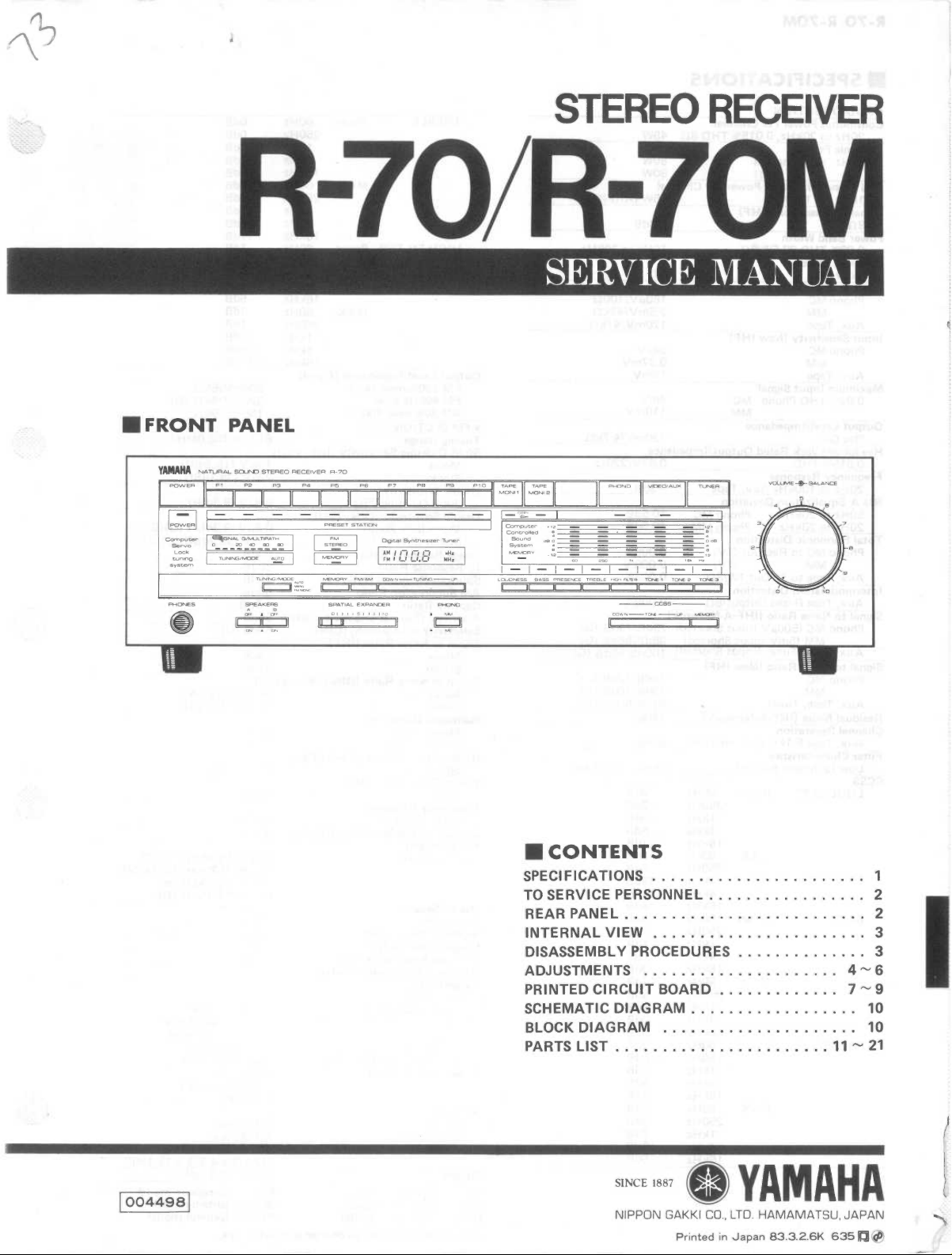
Yamaha R-70, R-70M Service Manual
R-70/R-70M
•
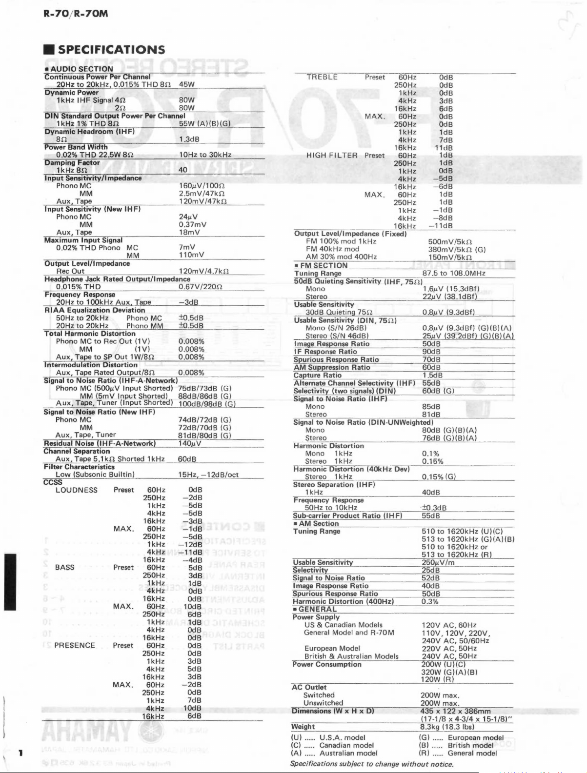
SPECIFICATIONS
I
1
•AUDIO
Continuous
Dynamic
DIN
Dynamic
Power Band
Damping
Input
Input
Maximum
Output
Headphone Jack Rated
Frequency Response
RIAA
Total
Intermodulation
Signal
Signal
Residual Noise
Channel Separation
Filter
ccss
SECTION
20Hz
1
1kHz1%THD8f2
an.
0.02%
1
Phono MC
Aux,
Phono MC
Aux,
0.02%
Rec
0.015%
20Hz
50Hz
20Hz
Phono
Aux
Aux,
Phono MC
Aux,
Phono
Aux,
Aux,
Low
LOUDNESS
BASS
PRESENCE
Power Per Channel
to
20kHz,
Power
kHz I HF
Standard
Headroom
THO
Factor
kHz
an
Sensitivity/Impedance
MM
Tape
Sensitivity
MM
Tape
Input
THO
Level/Impedance
Out
THO
to
Equalization
to
to
Harmonic
MC
MM
Tape
Tape Rated
to
Noise
MM
Tape,
to
Noise
MC
MM
Tape,
Tape
Characteristics
(Subsonic
0.015%
Signal
Output
Width
22.5W
(New
Signal
Phono MC
1 OOkHz
Deviation
20kHz
20kHz
Distortion
to
Rec
to
SP
Distortion
Ratio
(500µV
(5mV
Tuner
Ratio
Tuner
(!HF-A-Network)
5.1kn.
Builtin)
Preset
MAX.
Preset
MAX.
Preset
MAX.
THO
8n. 45W
4f2
2n.
Power Per Channel
(IHF)
an
IHF)
MM
Output/Impedance
Aux.
Tape
Phono MC
Phono
MM
Out
(1V)
(1V)
Out
1 W/8n.
Output/Sn.
UHF-A-Network)
Input
Shorted)
Input
Shorted)
(Input
Shorted)
(New
IHF)
Shorted
lkHz
60Hz
250Hz
1kHz
4kHz
16kHz
60Hz
250Hz
lkHz
4kHz
16kHz
60Hz
250Hz
1kHz
4kHz
16kHz
60Hz
250Hz
lkHz
4kHz
16kHz
60Hz
250Hz
1kHz
4kHz
16kHz
60Hz
250Hz
1kHz
4kHz
16kHz
80W
80W
55W(A)(B)(G)
1.3dB
1
OHz
40
1soµv11
2.
120mV
24µV
0.37mV
18mV
7mV
110mV
120mV
0.67V/220n.
-3dB
±o.5dB
±o.5dB
0.008%
0.008%
0.008%
0.008%
75dB/73dB
88dB/86dB
100dB/98dB
74dB/72dB
72dB/70dB
81dB/80dB
140µV
60d8
15Hz
-2d8
-5dB
-5dB
-
-1dB
-5dB
-12dB
-11d8
-
10dB
-2dB
lOdB
5mV
OdB
3dB
4dB
5dB
3dB
ldB
OdB
OdB
6dB
1dB
OdB
OdB
OdB
OdB
3dB
5dB
3dB
OdB
7dB
6dB
to
30kHz
oon.
/47kf2
/47kf2
/4.7kn.
-12d
--
---
(G)
(G)
(G)
(G)
(G)
(G)
B/oct
TREBLE
-
HIGH
FILTER
-
-----
Output
Level/Impedance
FM 100%
FM
40kHz
AM
30%
•FM
SECTION
Tuning
Range
50dB
Quieting
Mono
Stereo
Usable
Sensitivity
30dB Quieting 75!2
Usable
Sensitivity
Mono
(S/N
Stereo (S/N
Image Response
IF
Response
Spurious Response
AM
Suppression
Capture
Alternate
Selectivity
Signal
Signal
Harmonic
Harmonic
Stereo Separation (I
Frequency Response
Sub-carrier
•AM
Tuning
Usable
Selectivity
Signal
Image Response
Spurious Response
Harmonic
•GENERAL
Power
Power
AC
Dimensions (W x H x D)
Weight
(U) .....
(C) ..... Canadian model
(A) ..... Australian model
Ratio
Channel
(two
to
Noise
Mono
Stereo
to
Noise
Mono
Stereo
Distortion
Mono 1 kHz
Stereo 1 kHz
Distortion
Stereo 1
1kHz
50Hz
to
10kHz
Product
Section
Range
Sensitivity
to
Noise
Distortion
Supply
US
& Canadian Models
General Model and
European Model
& Australian Models
British
Consumption
Outlet
Switched
Unswitched
U.S.A
Specifications
Preset
250Hz
16kHz
MAX.
250Hz
16kHz
Preset
250Hz
MAX.
---~----'-1=6~k~H_z
mod
1 kHz
mod
mod
400Hz
Sensitivity
(DIN,
26d8)
46dB)
Ratio
Ratio
Ratio
Ratio
Selectivity
signals)
Ratio
Ratio
kHz
HF)
Ratio
Ratio
Ratio
Ratio
. model
subject
16kHz
250Hz
(Fixed)
(IHF,
75f2)
(IHF)
(DIN)
(IHF)
(DIN-UNWeighted)
(40kHz
Dev)
(I
HF)
(400Hz)
R-70M
to
change
60Hz
1
kHz
4kHz
60Hz
lkHz
4kHz
60Hz
1 kHz
4kHz
60Hz
1
kHz
4kHz
75f2)
without
OdB
OdB
OdB
3dB
6d8
OdB
OdB
ldB
7dB
11dB
1dB
1dB
OdB
-5d8
-6dB
1dB
1dB
-1d8
-8d8
_ _
-~11dBc:__
500mV/5kn.
380mV
150mV/5kn.
87.5
1.6µV
22µV
0.
8µV
0.8µV
25µV
50d8
90dB
70dB
60dB
1.
5d8
55d8
60dB
85d8
81d8
80dB
76d8
0.1%
0.15%
0.15% (G)
40d8
±o.3d8
55d8
510
513
510
513
250µV/m
25dB
52dB
40dB
50d8
0.3%
120V
11
240V
220V
240V
200W
320W
120W
200W
200W
435 x 122 x 386mm
(17-1/8 x 4-3/4 x 15-1/8)"
8.3kg
(G)
(B) ..... British model
(R) ..... General model
_
/5kn.
to
108.0MHz
(15.3d8f)
(38.1dBf)
(9.3dBf)
(9.3dBf)
(39.2dBf)
(G)
(G)(B)(A)
(G)(B)(A)
to
1620kHz
to
1620kHz
to
1620kHz
to
1620kHz
AC,
60Hz
OV, 1
20V,
AC,
50/60Hz
AC,
50Hz
AC,
50Hz
(U)(C)
(G)(A)(B)
(R)
max.
max.
(18.3 lbs)
..
... European model
notice.
____
(G)
(G)(B)(A)
(G)(B)(A)
(U)(C)
(G)(A)(B)
or
(R)
220V,
~
R-70/R-70M
•
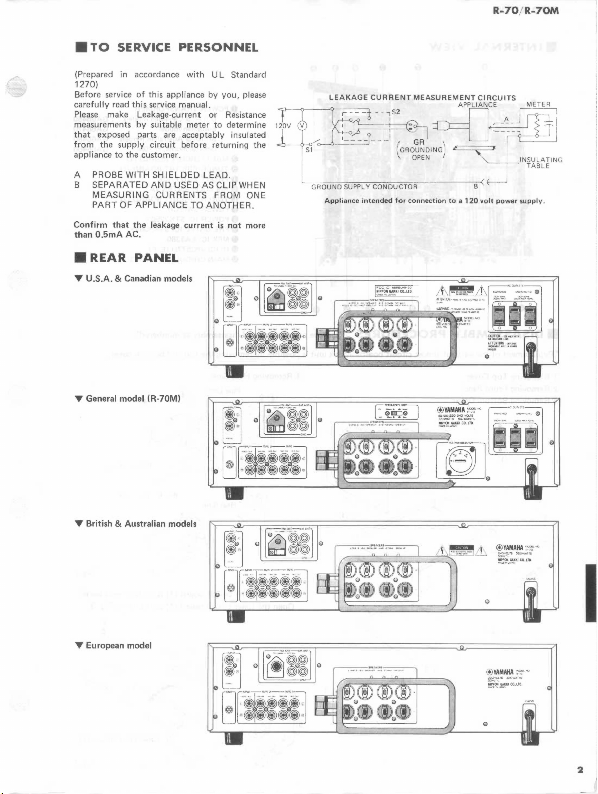
TO
SERVICE
PERSONNEL
(Prepared
1270)
Before service
carefully
Please make Leakage-current or Resistance
measurements by suitable meter
that
from
appliance
A
B SEPARATED AND
Confirm
than
•
,..
U.S.A. & Canadian models
in
accordance with
of
this appliance by you, please
read this service manual.
exposed parts are acceptably insulated
the
supply circui1t before returning the
to
the
customer.
PROBE WITH SHIELDED LEAD.
USED
MEASURING CURRENTS FROM ONE
PART
OF APPLIANCE
that
the
0.5mA
REAR
leakage
AC .
PANEL
AS
TO
ANOTHER.
current
UL
to
determine
CLIP
is
not
Standard
WHEN
more
LEAKAGE
Jv~-~~~
/~~
S1
L_
GROUND
Appliance
CURRENT
MEASUREMENT
---/ GR~
GROUNDING
~
OPEN
SUPPLY
CONDUCTOR
intended
for
connection
CIRCUITS
)
~_cNSULATl~G
--------------;~
B
to a 120
volt
power
~~~~~~u
l~o~'
M
,;~J,l~IC
::~~~.
I
TABLE
supply.
,..
General
,..
British & Australian models
,..
European
model
model
(R-70M)
~ Q ~lijJ
R:
illl
~j
Q
~lijJ
Q
:
Q
@YAMAHA
2.:iovo..rs
50Hl
~-
~~
~Kl
@YAMAHA
~'""
220VO,_~
320WAT'f5
5QHz'\..
~~~~Kl
CO.,lTD
CO.,LTO
L;J
:
liftl
,
2
R-70/R-70M
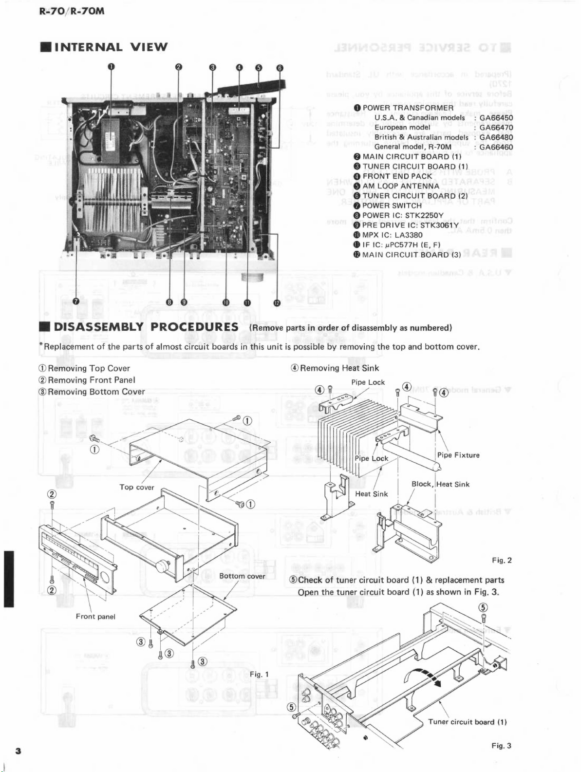
•1NTERNA
L
VIEW
I
C
DISASSEM
ement
of
Top
the
Cover
•Rep
a
CD
Removing p nel
.
BLY
parts
3
: f disassembly
OC
PR
I ost
circuit
of
am
RES
EDU
boards in this ·ng Heat Sink
(Remove par .
. unit
ts
in
is
possible y
@)
Remov1
4
~!~
order
~
o
b removing
11
0
POWER dian models .
@MAIN
A
TUNER
w
0
FRONT
0
AM
A
TUNER
v SWITCH
0 POWER
(i) POWER IC:
0 PRE
•
MPX
•
IF
4B
MAIN
p;pe
/ ' i'--
TRANSFORMER
SA
& Cana .
U · · · del ·
European
Bnt1s
General
LOOP
DRIVE
IC: µPC57
the
Lock
mo
. . h &
mod
CIRC~~I~
CIR
END
ACUIT
CIR
IC : LA37H (E, F)
CIRCU.IT
as
top
"©
'·
j~~
. odels :
Australian
el
R-70M
,OARD
BOARD
PACK
NTENNA
BOARD
TK2250Y
~C
·
STK3061
3~0
BOARD
numbered)
and bot
'i ©
--._J
•
I
m .
tom
(1)
(1)
(2)
y
(3)
cover.
.
GA66450
66470
GA
66480
GA
GA66460
.
I
~
=:~~~:~~
::~~~m
Cover
l~
v
Fig. 1
ililll~h°"i\
l
lllllll
1 t
!o
I
lt
~
.
Heats;nk
~
7i
· / I
·.
Block.
;pe
Foxtuce
!Heat
Sonk
I
Fig. 2
\ .
Tuner
3
c1rcu1
.,
board
111
Fig. 3
ADJUSTMENTS
R-70
1
R-70M
<CONFIRMATION
Before
adjustment
Note
1:
After
the
Step
1
2
4
5
<TUNER
•Before
Note
Confirmation
Power
supply
Gain
DC
offset
PHONO
amp
ADJUSTMENT>
adjustment
1)
After
the
minutes
most
Note
Note
2)
3)
Adjust
screw
Do
not
stable
the
driver.
forget
OF
power
voltage
Power
before
operation.
OSC
AUDIO
switch
IC414,
and E (Leh)
across
E (Reh)
IC414,
and E (Leh)
across
E (Reh)
PL,PR
switch
measuring,
coil
to
keep
SECTION>
is
pushed
Test
point
+8
-8
+16
-16
+12
+5
+a
-a
across
pin
13 and
across
pin
13
is
pushed
to
and I FT
the
bottom
on,
wait
for 5 minutes
Rating
-43V
-16V ± 2V
+12.5V ± 1V
+5.5V ± 0.5V
pin
4
pin
4
and
+120mV ± 20mV
on,
wait
sure
of
for
the
be
with a nonferrous
cover
on.
or
standard
+43V
±av
±av
+16V ± 2V
+av±
1v
-av±
1V
+10V±1V
OV ±
70mV
5
before
measuring,
•Measuring
FM
SG : FM
SSG
:
AM SG :
OSC
DIST.
FC
ACVM
:
M:
:
: AC
to
be
sure
of
the
Adjustment
Make sure
comes
within
Models
u.c
G
A.
B
Apply a 1kHz,100mV
signal
to
the
Apply
a 1
signal
to
PHONO
Apply a 1kHz,
signal
to
PHONO
method
that
AC
line
AC line voltage
120V
± 10%
220V
± 10%
240V
± 10%
points
"BL"
kHz,
2.5mV
sine wave
INPUT
160µV
sine wave
INPUT
voltage
sine wave
instruments abbreviation
signal
generate.
Stereo
signal
generator
AM
signal
generator
Oscilloscope
Distortion
Frequency
volt
meter
counter
meter
most
and
"BR"
stable
No
PHONO
selector
set
PHONO
selector
set
operation.
Remark
load
----
"MM"
"MC"
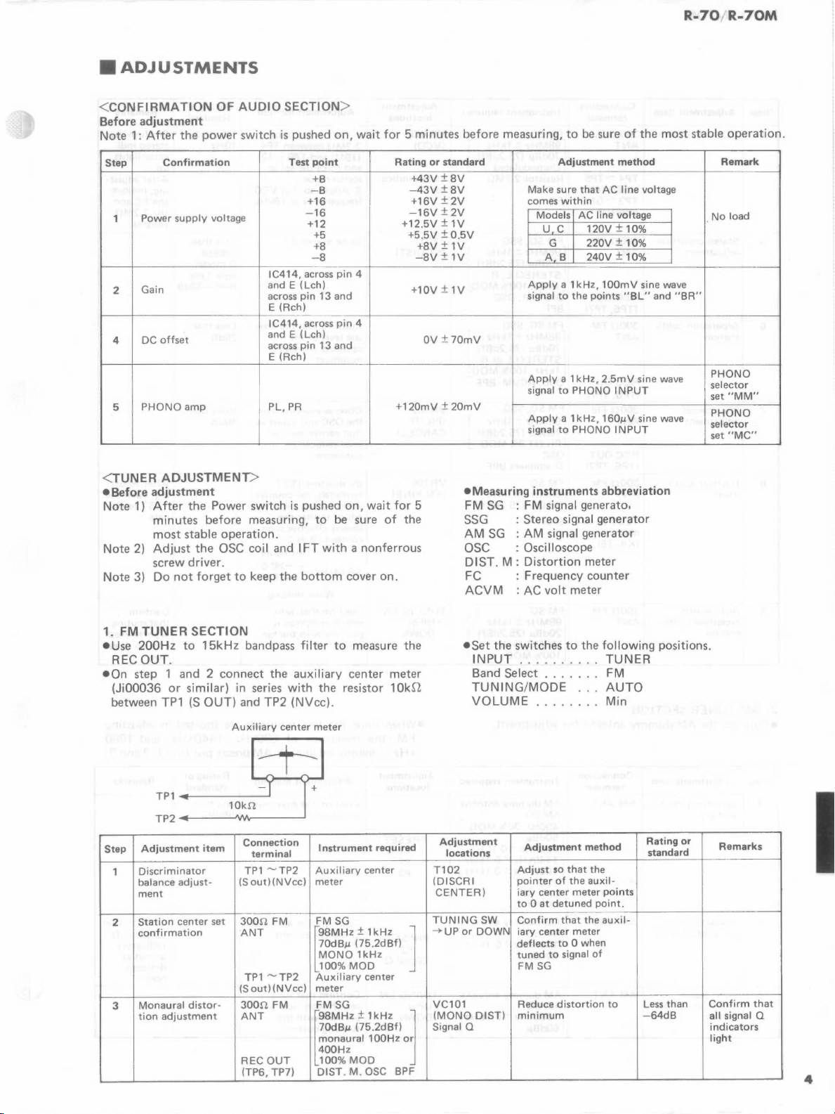
1. FM
TUNER
•Use
200Hz
REC
OUT.
•On
step 1 and 2 connect
(Ji00036
between
Adjustment
Step
Discriminator
1
balance
ment
Station
2
confirmation
Monaural
3
tion
to
or
similar)
TP1 (S
adjust-
center
adjustment
SECTION
15kHz
OUT)
Auxiliary
item
set
distor-
bandpass
the
in series
and
Connection
TP1
(Sout)(NVcc)
300S1
ANT
TP1
(S
300S1
ANT
REC
(TP6, TP7)
TP2
center
terminal
"'TP2
FM
"'TP2
out)
(NV
FM
OUT
with
filter
to
measure
auxiliary
the
center
resistor
(NVcc).
meter
Instrument
Aux
i I
iary
meter
FM
SG
~98MH'
70d8µ
(75.2dBf)
MONO
100%
MOD
Auxiliary
cc)
meter
FM
SG
[98MH'
70dBµ
(75.2dBf)
monaural
400Hz
100%
MOD
DIST.
M.
center
± 1
kH'
1kHz
center
± 1
100Hz
OSC
meter
1 Okr!
required
kH'
or
BPF
the
l
j
•Set
INPUT
Band
TUNING/MODE
VOLUME
Adjustment
locations
T102
(DISCRI
CENTER)
TUNING
~up
or
VC101
(MONO
Signal Q
the
SW
DOWN
DIST)
switches
. . . . . . .
Select
. . . . FM
. . . . . Min
Adjustment
Adjust
pointer
iary
center
to 0 at
detuned
Confirm
iary
center
deflects
tuned
to
FM
SG
Reduce
minimum
to
the
method
so
that
of
the
meter
that
the
meter
to
0 when
signal
distortion
following
TUNER
AUTO
the
auxil-
points
point.
auxil-
of
to
positions.
Rating
standard
Less
than
-64d8
or
Remarks
Confirm
all signal Q
indicators
light
I
that
4
R-70/R-70M
I
Step
4
5
6
7
8
9
Adjustment
VCO
adjustment
Stereo
distortion
adjustment
Separation
mat
ion
Pi
lot
cancel
adjustment
If
offset
ment
Auto
reception
mat
adjust-
search
ion
item
confir-
confir-
Connection
terminal
300!1
FM
ANT
TP4
"'TP5
(19M)
(+12)
TP3
"'GND
(19kHz)
300!1
FM
ANT
REC
OUT
TP7)
(TP6,
300!1
FM
ANT
REC
OUT
(T.P6, TP7)
300!1
FM
ANT
REC
OUT
(TP6, TP7)
300!1
FM
ANT
TEST
termi-
nals
(K4,
T6)
300!1
FM
ANT
Instrument
FM
[98MH'
70dBµ
Unmodulated
Resistor
FC
FM
[98MH'
70dBµ
STEREO
1kHz,100%
DIST.
BPF
FM
r98MHd1kH'
70dBµ
STEREO
1kHz,100%
OSC,
FM
[98MHd 1 kH'
70d8µ
PILOT9%
osc
Disconnect BPF
FM
[98MHz
70d8µ
Short
FM
[98MH'
20d8µ
MONO
100%
SG
SG,
M,
SG,
ACVM,
SG,
SG
SG
MOD
required
± 1
kH'
(75.2dBf)
2.2Mn
SSG
± 1
kH'
(75.2dBf)
L,
R
MOD
OSC
SSG
(75.2dBf)
Lor
MOD
SSG
(75.2d8f)
MOD
± 1
kHz
(75.2dBf)
± 1
kH'
(25.2dBf)
1kHz
R
BPF
]
]
l
]
J
]
Adjustment
locations
VR103
(VCO)
Stereo indicator
T101
(ST
DIST)
VR102
(PILOT
CANCEL)
VR106
(FM
FINE)
TUNING
-+UP
or
DOWN
SW
Rating
Adjustment
CD
Connect
2.2Mn
between TP4
(19M)
and
and
force
stereo
mode.
®
Adjust
frequency
Same
as
step 3
Confirm
age
opposite
minimum
Observe
the
that
level
minimum
By
terminals,
shifts
adjust
lowest
comes
that
level
of
channel
waveform
OSC and adjust
carrier
reduced
shorting
by
one
so
that
effective
to 9 or
resistor
TP5
the
so
that
is
at
the
leakage
TEST
the
This
method
(+12)
set in
VCO
19kHz
the
leakis
to
counter
digit,
the
digit
0.
figure
--
on
so
then
~
standard
19kHz
10Hz
Less
than
-48dB
G
model
only
Less
than
-33dB
-
Less
than
26dB
More
than
46dB
or
Remarks
±
Confirm
stereo
ca
tor
up.
After
ing,
remove
the
FC
the
2.2Mn
resistor.
After
ing,
open
TEST
nals.
98.0MHz-c~g.·~
When
shifting
Confirm
search
possible
ing
reception
with
button.
that
auto
the
is
tun-
Confirm
that
muting
is
performed
at
auto
ti
on.
that
indi-
I ights
adjust-
and
adjust-
the
termi-
recep- I
5
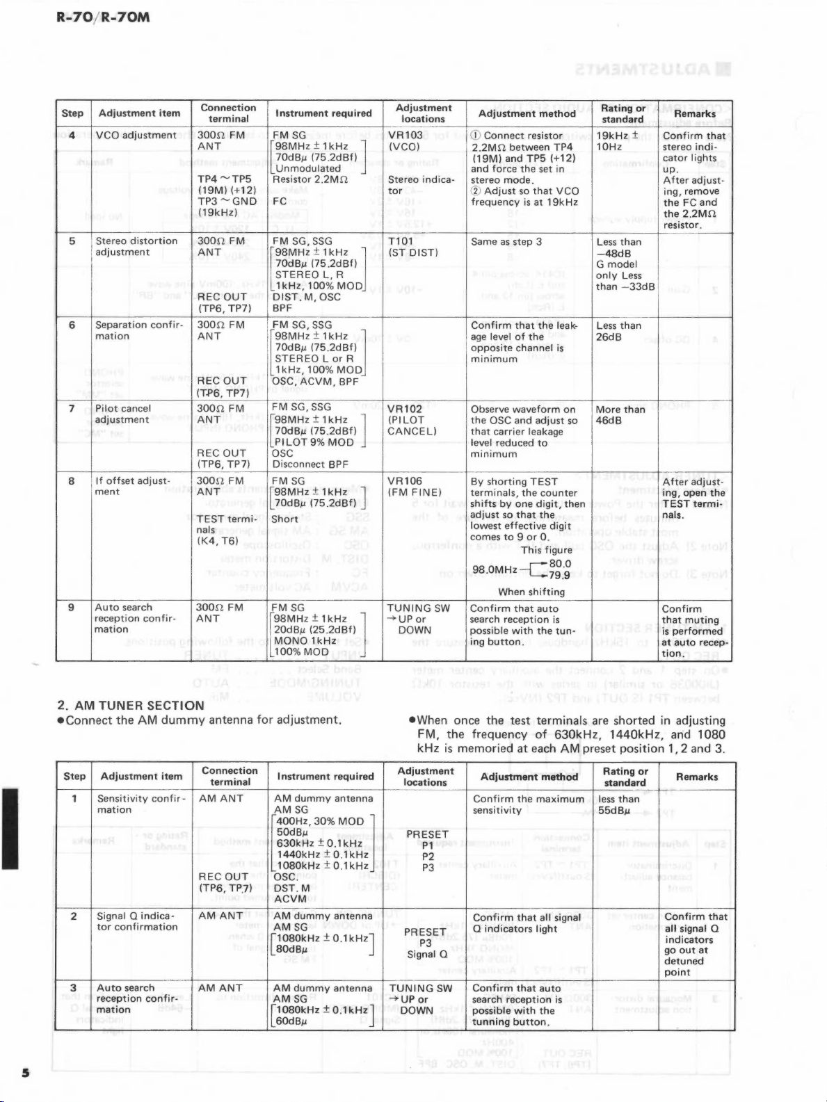
2.
AM
TUNER SECTION
•Connect
Step
Sensitivity
1
mat
Signal Q
2
tor
Auto
3
reception
mat
the
AM
Adjustment
ion
indica-
confirmation
search
confir-
ion
dummy
item
confir-
antenna
Connection
terminal
AMANT
REC
OUT
(TP6, TP,7)
AM
ANT
AM
ANT
for
adjustment.
Instrument
AM
AM
l
400H,,
50d8µ
630kHz
1440kHz
1080kHz
OSC.
DST.M
ACVM
AM
AMSG
[1080kHz ± 0.1kHzJ
80d8µ
AM
AMSG
[1080kHz
60d8µ
dummy
SG
30%
± 0.1
dummy
dummy
required
antenna
± 0.1
± 0.
antenna
antenna
± 0.1
MOD
kHz
kHz
1kHz
kHz
l
TUNING
-+UP
J
•When
once the test terminals
FM, the frequency
kHz
is
memoried at
Adjustment
locations
PRESET
P1
P2
P3
PRESET
P3
Signal Q
SW
or
DOWN
Adjustment
Confirm
sensitivity
Confirm
Q
Confirm
search
possible
tunning
the
that
indicators
that
reception
with
button.
of
630kHz,
each
AM
method
maximum
all signal
light
auto
is
the
are
shorted in adjusting
1440kHz,
and
1080
preset position 1, 2 and 3.
Rating
or
standard
less
than
55d8µ
Remarks
Confirm
all
signal 0
indicators
go
out
at
detuned
point
that
I
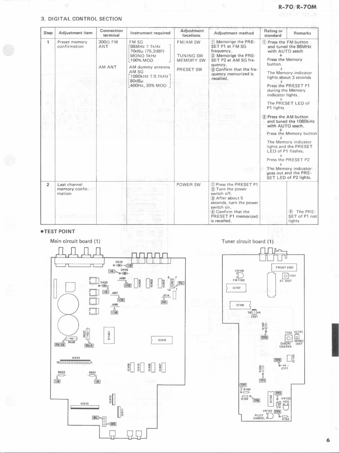
3.
DIGITAL
CONTROL
R-70,/R-70M
SECTION
Step
1
2
Adjustment
Preset
memory
confirmation
Last
channel
memory
mat
confir-
ion
item
Connection
terminal
300D
FM
ANT
AM
ANT
Instrument
FM
[98MH'
70dBµ
MONO
100%
AM
AM
[1080kH' ±0.1kH']
80dBµ
400Hz,
SG
± 1
(75.2dBf)
1kHz
MOD
dummy
SG
30%
required
kH'
antenna
MOD
l
Adjustment
locations
FM/AM
TUNING
MEMORY
PRESET
POWER
SW
SW
SW
SW
SW
Adjustment
CD
Memorige
SET
P1
frequency.
®
Memorige
SET
P2
quency.
@Confirm
quency
recalled.
CD
Press
®Turn
switch
off.
@After
seconds,
switch
on.
©Confirm
PRESET
is
recalled.
method
the
at
FM
SG
the
at
AM
SG
that
the
memorized
the
PRESET
the
power
about
5
turn
the
that
the
P1
memorized
PRE-
PRE-
fre-
freis
power
P1
Rating
standard
CD
Press
and
with
Press
button.
The
lights
Press
during
indicator
The
P1
lights.
® Press
and
with
Press
The
lights
LED
Press
The
goes
SET
or
the
FM
tuned
AUTO
+
the
Memory
t
Memory
about
t
the
PRESET
the
lights.
t
PRESET
the
AM
tuned
AUTO
+
the
Memory
t
Memory
and
the
of
P1
t
the
PRESET
t
Memory
out
and
LED
of
@
SET
lights
Remarks
button
the
98MHz
seach
indicator
3 seconds
Memory
LED
button
the
1080kHz
seach.
indicator
PRESET
flashes.
indicator
the
P2
lights.
The
of
P1
of
button
P2
PRE-
PRE-
P1
!
I
not
•TEST
Main
POINT
circuit
D
,.j
•
A R528
~
IC414
1sloooooooooooooooo
R503
~
board (1)
DD
@---@..
DD
DD
DD
~
I,
R501
-c:J-~
D420 J
~
J497 -
J499
~
490
,.},_
l..:!EJ
~
o~
u
IC415
Tuner
circuit
VR106
:0
FM
FINE
IC107 I
IC106 5
-c:::H!l
R159
board ( 1)
I FRONT
0
T6mk4
TEST
~
~
PILOT
CANCEL R152
~
rn
VR102
IT.P!l
D··~
END
I
J~,~'"
T102
VC101
[QJ@NO
DISCRI DIST
CENTER
D~
@-il-
C171
VR103
"'vco
~
~
tJ
-
6
 Loading...