

Page 1

SERVICE MANUAL
PZ50W
PZ50GTW
PZ50FXW
PZ50MW
PZ50VTW
PZ50MPW
LIT-12618-02-58 8GC-28197-10
Page 2

Page 3
NOTICE
This manual was written by the Yamaha Motor
Company primarily for use by Yamaha dealers and
their qualified mechanics. It is not possible to put an
entire mechanic’s education into one manual, so it
is assumed that persons using this book to perform
maintenance and repairs on Yamaha snowmobiles
have a basic understanding of the mechanical concepts and procedures inherent in snowmobile
repair. Without such knowledge, attempted repairs
or service to this model may render it unfit and/or
unsafe to use. Yamaha Motor Company, Ltd. is
continually striving to improve all models manufactured by Yamaha. Modifications and significant
changes in specifications or procedures will be forwarded to all authorized Yamaha dealers and will,
where applicable, appear in future editions of this
manual.
HOW TO USE THIS MANUAL
Particularly important information is distinguished in
this manual by the following notations:
The Safety Alert Symbol means ATTENTION! BE
ALERT! YOUR SAFETY IS INVOLVED!
WARNING
Failure to follow WARNING instructions could result
in severe injury or death to the snowmobile operator, a bystander, or a person inspecting or repairing
the snowmobile.
CAUTION:
A CAUTION indicates special precautions that
must be taken to avoid damage to the snowmobile.
NOTE:
A NOTE provides key information that can make
procedures easier or clearer.
PZ50W, PZ50GTW, PZ50FXW, PZ50MW,
PZ50VTW, PZ50MPW
SERVICE MANUAL
©2006 by Yamaha Motor
Corporation, U.S.A.
1st Edition, July 2006
All rights reserved. Any reprinting or
unauthorized use without the written
permission of Yamaha Motor Corporation,
U.S.A. is expressly prohibited.
Printed in U.S.A.
P/N.LIT-12618-02-58
MANUAL FORMAT
All of the procedures in this manual are organized
in a sequential, step-by-step format. The information has been compiled to provide the mechanic
with an easy to read, handy reference that contains
comprehensive explanations of all inspection,
repair, assembly, and disassembly operations.
In this revised format, the condition of a faulty component will precede an arrow symbol and the
course of action required to correct the problem will
follow the symbol, e.g.,
• Bearings
Pitting/damage → Replace.
EXPLODED DIAGRAM
Each chapter provides exploded diagrams before
each disassembly section to facilitate correct disassembly and assembly procedures.
Page 4
1 2
GEN
INFO
34
INSP
ADJ
POWR
CHAS
TR
56
ENG
78
COOL
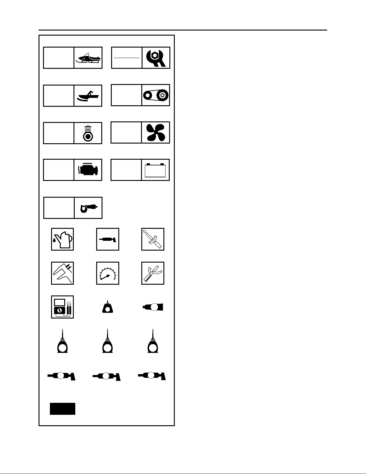
ILLUSTRATED SYMBOLS
(Refer to the illustration)
Illustrated symbols 1 to 9 are designed as thumb
tabs to indicate the chapter’s number and content.
1 General information
2 Periodic inspection and adjustment
3 Chassis
4 Power train
5 Engine
6 Cooling system
7 Fuel injection system
8 Electrical
9 Specifications
–+
9
FI
ELEC
SPEC
0AB
T
.
R
.
CDE
FGH
LT
IJK
E
LMN
B
G
LS
5
M
M
Illustrated symbols 0 to F are used to identify the
specifications which appear.
0
Filling fluid
A Lubricant
B Tightening
C Wear limit, clearance
D Engine speed
E Special tool
FΩ, V, A
Illustrated symbols G to O in the exploded diagram
indicate grade of lubricant and location of lubrication point.
G Apply locking agent (LOCTITE
H Apply Yamabond No.5
I Apply engine oil
J Apply gear oil
K Apply molybdenum disulfide oil
L Apply wheel bearing grease
M Apply low-temperature lithium-soap base grease
N Apply molybdenum disulfide grease
O Use new one
®
®
)
O
New
Page 5
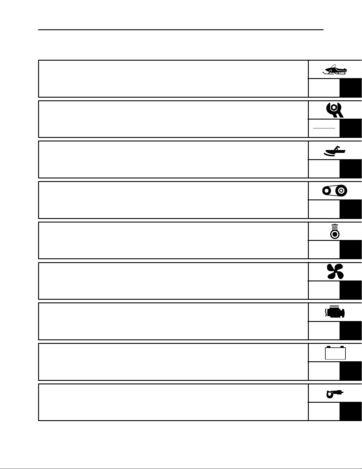
INDEX
GENERAL INFORMATION
PERIODIC INSPECTION AND
ADJUSTMENT
CHASSIS
POWER TRAIN
ENGINE
GEN
INFO
INSP
ADJ
CHAS
POWR
TR
ENG
1
2
3
4
5
COOLING SYSTEM
FUEL INJECTION SYSTEM
ELECTRICAL
SPECIFICATIONS
COOL
FI
– +
ELEC
SPEC
6
7
8
9
Page 6

CHAPTER 1.
GENERAL INFORMATION
MACHINE IDENTIFICATION
FRAME SERIAL NUMBER ......................... 1-1
ENGINE SERIAL NUMBER........................ 1-1
............................ 1-1
CYLINDER HEAD BREATHER HOSE
INSPECTION ............................................ 2-23
THROTTLE BODY JOINTS
INSPECTION ............................................ 2-23
CHECKING THE AIR FILTER
ELEMENT ................................................. 2-24
EXHAUST SYSTEM INSPECTION .......... 2-25
IMPORTANT INFORMATION
PREPARATION FOR REMOVAL AND
DISASSEMBLY........................................... 1-2
ALL REPLACEMENT PARTS..................... 1-2
GASKETS, OIL SEALS, AND O-RINGS..... 1-3
LOCK WASHERS/PLATES AND COTTER
PINS............................................................ 1-3
BEARINGS AND OIL SEALS ..................... 1-3
CIRCLIPS ................................................... 1-3
LOCTITE
SPECIAL TOOLS
FOR TUNE UP............................................ 1-4
FOR ENGINE SERVICE............................. 1-4
FOR POWER TRAIN SERVICE ................. 1-7
FOR FUEL INJECTION SERVICE ............. 1-8
FOR ELECTRICAL SERVICE .................... 1-8
®
................................................... 1-3
............................................. 1-4
.......................... 1-2
CHAPTER 2.
PERIODIC INSPECTION
AND ADJUSTMENT
POWER TRAIN
SHEAVE OFFSET ADJUSTMENT ........... 2-26
DRIVE V-BELT.......................................... 2-28
ENGAGEMENT SPEED CHECK.............. 2-29
PARKING BRAKE ADJUSTMENT............ 2-29
BRAKE FLUID LEVEL INSPECTION ....... 2-30
BRAKE PAD INSPECTION....................... 2-31
BRAKE HOSE INSPECTION.................... 2-32
AIR BLEEDING (HYDRAULIC BRAKE
SYSTEM) .................................................. 2-32
DRIVE CHAIN ........................................... 2-33
TRACK TENSION ADJUSTMENT............ 2-35
SLIDE RUNNER INSPECTION ................ 2-37
MAXIMIZING DRIVE TRACK LIFE ........... 2-37
CHASSIS
SKI/SKI RUNNER ..................................... 2-39
STEERING SYSTEM ................................ 2-39
LUBRICATION .......................................... 2-41
ELECTRICAL
HEADLIGHT BEAM ADJUSTMENT ......... 2-42
BATTERY INSPECTION........................... 2-42
FUSE INSPECTION.................................. 2-48
............................................... 2-26
........................................................ 2-39
................................................. 2-42
INTRODUCTION
PERIODIC MAINTENANCE CHART FOR
THE EMISSION CONTROL SYSTEM
GENERAL MAINTENANCE AND
LUBRICATION CHART
ENGINE
............................................................ 2-4
SPARK PLUGS........................................... 2-4
FUEL LINE INSPECTION........................... 2-4
COOLING SYSTEM.................................... 2-5
VALVE CLEARANCE ADJUSTMENT ........ 2-7
THROTTLE BODY
SYNCHRONIZATION ............................... 2-13
ENGINE IDLE SPEED ADJUSTMENT..... 2-14
THROTTLE CABLE FREE PLAY
ADJUSTMENT.......................................... 2-15
THROTTLE OVERRIDE SYSTEM
(T.O.R.S.) CHECK .................................... 2-16
COMPRESSION PRESSURE
MEASUREMENT ...................................... 2-17
ENGINE OIL LEVEL INSPECTION .......... 2-19
ENGINE OIL REPLACEMENT ................. 2-20
............................................... 2-1
.............. 2-1
.................................... 2-2
TUNING
.......................................................... 2-50
CLUTCH.................................................... 2-50
GEAR SELECTION................................... 2-55
FRONT SUSPENSION ............................. 2-61
REAR SUSPENSION................................ 2-63
CHAPTER 3.
CHASSIS
COWLINGS
PZ50/PZ50GT/PZ50FX/PZ50M .................. 3-1
PZ50VT/PZ50MP ........................................ 3-3
STEERING
PZ50W/PZ50GT/PZ50FX/PZ50M............... 3-4
PZ50VT/PZ50MP ........................................ 3-6
REMOVAL................................................. 3-10
INSPECTION ............................................ 3-10
INSTALLATION......................................... 3-11
SKI
.................................................................. 3-14
PZ50/PZ50GT/PZ50FX/PZ50VT “USA/
Canada” .................................................... 3-14
...................................................... 3-1
........................................................ 3-4
Page 7

PZ50VT “Europe”/PZ50MP....................... 3-15
PZ50M ...................................................... 3-16
INSPECTION ............................................ 3-17
FRONT SUSPENSION ................................... 3-18
PZ50/PZ50FX/PZ50M............................... 3-18
PZ50GT/PZ50VT/PZ50MP ....................... 3-20
HANDLING NOTES .................................. 3-22
INSPECTION ............................................ 3-22
INSTALLATION ........................................ 3-23
CHAPTER 4.
POWER TRAIN
PRIMARY SHEAVE AND DRIVE V-BELT ....... 4-1
REMOVAL .................................................. 4-3
DISASSEMBLY........................................... 4-3
INSPECTION .............................................. 4-4
ASSEMBLY................................................. 4-6
INSTALLATION .......................................... 4-9
SECONDARY SHEAVE ................................. 4-10
DISASSEMBLY......................................... 4-12
INSPECTION ............................................ 4-12
ASSEMBLY............................................... 4-13
INSTALLATION ........................................ 4-14
DRIVE CHAIN................................................. 4-15
REMOVAL ................................................ 4-16
INSPECTION ............................................ 4-16
INSTALLATION ........................................ 4-18
SECONDARY SHAFT .................................... 4-19
PZ50 ......................................................... 4-19
REMOVAL ................................................ 4-20
INSPECTION ............................................ 4-20
INSTALLATION ........................................ 4-20
SECONDARY SHAFT AND DRIVE
CHAIN INSTALLATION ............................ 4-22
BRAKE CALIPER ASSEMBLY ................. 4-37
BRAKE CALIPER INSTALLATION ........... 4-37
INSPECTION ............................................ 4-39
BRAKE MASTER CYLINDER
ASSEMBLY............................................... 4-39
INSTALLATION......................................... 4-39
SLIDE RAIL SUSPENSION............................ 4-40
PZ50/PZ50GT/PZ50FX/PZ50M ................ 4-40
PZ50VT/PZ50MP ...................................... 4-45
REMOVAL................................................. 4-51
INSPECTION ............................................ 4-51
ASSEMBLY............................................... 4-51
INSTALLATION......................................... 4-55
FRONT AXLE AND TRACK ........................... 4-56
INSPECTION ............................................ 4-57
INSTALLATION......................................... 4-57
CHAPTER 5.
ENGINE
SEAT AND FUEL TANK................................... 5-1
PZ50/PZ50GT/PZ50FX/PZ50M .................. 5-1
BACKREST AND PASSENGER SEAT ........... 5-3
PZ50VT/PZ50MP ........................................ 5-3
RIDER SEAT AND FUEL TANK ...................... 5-5
PZ50VT/PZ50MP ........................................ 5-5
REMOVAL................................................... 5-7
INSTALLATION........................................... 5-8
EXHAUST PIPE AND MUFFLER ..................... 5-9
PZ50/PZ50GT/PZ50FX/PZ50M .................. 5-9
PZ50VT/PZ50MP ...................................... 5-10
INSTALLATION......................................... 5-11
OIL TANK ....................................................... 5-12
SECONDARY SHAFT AND REVERSE
GEAR CASE................................................... 4-23
PZ50GT/PZ50FX/PZ50M/PZ50VT/
PZ50MP .................................................... 4-23
REMOVAL ................................................ 4-27
INSPECTION ............................................ 4-28
ASSEMBLY............................................... 4-28
INSTALLATION ........................................ 4-29
SECONDARY SHAFT AND DRIVE
CHAIN INSTALLATION ............................ 4-30
BRAKE ........................................................... 4-31
BRAKE PAD REPLACEMENT ................. 4-33
BRAKE CALIPER DISASSEMBLY ........... 4-36
BRAKE CALIPER INSPECTION
AND REPAIR ............................................ 4-36
ENGINE ASSEMBLY ..................................... 5-13
HOSE AND LEADS................................... 5-13
ENGINE ASSEMBLY ................................ 5-15
REMOVAL................................................. 5-16
INSTALLATION......................................... 5-16
CAMSHAFTS.................................................. 5-18
CYLINDER HEAD COVER ....................... 5-18
CAMSHAFTS ............................................ 5-19
REMOVAL................................................. 5-20
INSPECTION ............................................ 5-21
INSTALLATION......................................... 5-25
Page 8

CYLINDER HEAD........................................... 5-28
REMOVAL ................................................ 5-29
INSPECTION ............................................ 5-29
INSTALLATION ........................................ 5-30
VALVES AND VALVE SPRINGS................... 5-32
REMOVAL ................................................ 5-33
INSPECTION ............................................ 5-34
INSTALLATION ........................................ 5-38
A.C. MAGNETO ROTOR AND STARTER
CLUTCH ......................................................... 5-41
REMOVAL ................................................ 5-42
INSPECTION ............................................ 5-43
INSTALLATION ........................................ 5-44
OIL PAN AND OIL PUMP .............................. 5-46
REMOVAL ................................................ 5-49
INSPECTION ............................................ 5-49
INSTALLATION ........................................ 5-50
BALANCER .................................................... 5-52
REMOVAL ................................................ 5-54
INSPECTION ............................................ 5-55
INSTALLATION ........................................ 5-55
CHAPTER 7.
FUEL INJECTION SYSTEM
FUEL INJECTION SYSTEM ............................. 7-1
WIRING DIAGRAM ..................................... 7-2
ECU SELF-DIAGNOSTIC FUNCTION ....... 7-4
SELF-DIAGNOSTIC FUNCTION TABLE.... 7-4
TROUBLESHOOTING CHART................... 7-6
DIAGNOSTIC MODE .................................. 7-7
TROUBLESHOOTING DETAILS .............. 7-14
OIL PRESSURE SWITCH ........................ 7-28
INTAKE AIR TEMPERATURE
SENSOR ................................................... 7-28
THROTTLE BODY.......................................... 7-29
INJECTORS.............................................. 7-30
INSPECTION ............................................ 7-31
PRESSURE REGULATOR
OPERATION ............................................. 7-31
INSPECTION AND ADJUSTMENT .......... 7-32
CHAPTER 8.
ELECTRICAL
CRANKCASE ................................................. 5-58
CRANKCASE............................................ 5-58
CONNECTING RODS AND PISTONS ..... 5-59
CRANKSHAFT.......................................... 5-60
REMOVAL ................................................ 5-61
INSPECTION ............................................ 5-63
INSTALLATION ........................................ 5-73
CHAPTER 6.
COOLING SYSTEM
RADIATOR AND HEAT EXCHANGER............ 6-1
INSPECTION .............................................. 6-3
INSTALLATION .......................................... 6-4
THERMOSTAT ................................................. 6-5
INSPECTION .............................................. 6-6
INSTALLATION .......................................... 6-6
WATER PUMP.................................................. 6-8
DISASSEMBLY......................................... 6-10
INSPECTION ............................................ 6-10
ASSEMBLY............................................... 6-11
INSTALLATION ........................................ 6-12
SWITCH INSPECTION ..................................... 8-1
SWITCH INSPECTION ............................... 8-1
INSPECTING A SWITCH SHOWN IN
THE MANUAL ............................................. 8-1
IGNITION SYSTEM .......................................... 8-2
CIRCUIT DIAGRAM.................................... 8-2
TROUBLESHOOTING ................................ 8-4
IGNITION SPARK GAP .............................. 8-6
IGNITION COIL........................................... 8-6
CRANKSHAFT POSITION SENSOR ......... 8-7
THROTTLE OVERRIDE SYSTEM
(T.O.R.S.).................................................... 8-8
ENGINE STOP SWITCH ............................ 8-9
THROTTLE SWITCH .................................. 8-9
MAIN SWITCH .......................................... 8-10
ELECTRICAL STARTING SYSTEM .............. 8-11
CIRCUIT DIAGRAM.................................. 8-11
TROUBLESHOOTING .............................. 8-12
STARTER MOTOR ................................... 8-14
CHARGING SYSTEM ..................................... 8-19
CIRCUIT DIAGRAM.................................. 8-19
TROUBLESHOOTING .............................. 8-20
BATTERY.................................................. 8-21
A.C. MAGNETO ........................................ 8-21
Page 9

LIGHTING SYSTEM ....................................... 8-22
CIRCUIT DIAGRAM.................................. 8-22
TROUBLESHOOTING.............................. 8-24
BULB(S).................................................... 8-26
HEADLIGHT BEAM SWITCH ................... 8-26
HEADLIGHT RELAY................................. 8-27
LOAD CONTROL RELAY......................... 8-27
SIGNAL SYSTEM........................................... 8-28
CIRCUIT DIAGRAM.................................. 8-28
TROUBLESHOOTING.............................. 8-30
BRAKE LIGHT SWITCH ........................... 8-38
DRIVE POSITION SWITCH AND
REVERSE POSITION SWITCH
(PZ50GT/PZ50FX/PZ50M/PZ50VT/
PZ50MP)................................................... 8-38
DC BACK BUZZER (PZ50GT/PZ50FX/
PZ50M/PZ50VT/PZ50MP) ........................ 8-38
COOLANT TEMPERATURE SENSOR .... 8-39
OIL LEVEL SWITCH................................. 8-40
FUEL SENDER......................................... 8-40
SPEED SENSOR...................................... 8-41
KNOCK SENSOR ..................................... 8-41
GRIP WARMER SYSTEM .............................. 8-42
CIRCUIT DIAGRAM.................................. 8-42
TROUBLESHOOTING.............................. 8-44
GRIP AND THUMB WARMER ................. 8-46
GRIP/THUMB WARMER ADJUSTMENT
SWITCH.................................................... 8-46
PASSENGER GRIP WARMER
(PZ50VT) .................................................. 8-47
PASSENGER GRIP WARMER SWITCH
(PZ50VT) .................................................. 8-47
PASSENGER GRIP WARMER RELAY
(PZ50VT/PZ50MP) ................................... 8-48
CHAPTER 9.
SPECIFICATIONS
GENERAL SPECIFICATIONS.......................... 9-1
MAINTENANCE SPECIFICATIONS................. 9-5
ENGINE ...................................................... 9-5
POWER TRAIN......................................... 9-10
CHASSIS .................................................. 9-16
ELECTRICAL ............................................ 9-18
TIGHTENING TORQUE.................................. 9-21
ENGINE .................................................... 9-21
POWER TRAIN......................................... 9-23
CHASSIS .................................................. 9-25
GENERAL TORQUE SPECIFICATIONS ....... 9-27
DEFINITION OF UNITS .................................. 9-27
CABLE ROUTING .......................................... 9-29
COOLING SYSTEM
(PZ50M/PZ50VT/PZ50MP) ............................. 8-50
CIRCUIT DIAGRAM.................................. 8-50
TROUBLESHOOTING.............................. 8-52
RADIATOR FAN MOTOR......................... 8-53
RADIATOR FAN MOTOR RELAY ............ 8-53
DRIVE/REVERSE SELECTING SYSTEM
(PZ50GT/PZ50FX/PZ50M/PZ50VT/
PZ50MP)......................................................... 8-54
CIRCUIT DIAGRAM.................................. 8-54
TROUBLESHOOTING.............................. 8-56
GEAR MOTOR ......................................... 8-57
GEAR MOTOR RELAY 1.......................... 8-58
GEAR MOTOR RELAY 2.......................... 8-58
GEAR MOTOR RELAY 3.......................... 8-59
Page 10
GEN
MACHINE IDENTIFICATION
GENERAL INFORMATION
MACHINE IDENTIFICATION
FRAME SERIAL NUMBER
The frame serial number 1 is located on the right-hand side of the frame
(just below the front of the seat).
ENGINE SERIAL NUMBER
The engine serial number 1 is located on the left-hand side of the crankcase.
NOTE:
Designs and specifications are subject to change without notice.
INFO
1-1
Page 11

GEN
IMPORTANT INFORMATION
IMPORTANT INFORMATION
PREPARATION FOR REMOVAL AND DISASSEMBLY
INFO
1. Remove all dirt, mud, dust, and foreign material before removal and
disassembly.
While cleaning, take care to protect the electrical parts, such as relays,
switches, motor, resistors, controllers, etc., from high pressure water
splashes.
2. Use proper tools and cleaning equipment.
Refer to “SPECIAL TOOLS”.
3. When disassembling the machine, keep mated parts together. This
includes gears, cylinders, pistons, and other parts that have been
“mated” through normal wear. Mated parts must be reused or replaced
as an assembly.
4. During disassembly of the machine, clean all parts and place them in
trays in the order of disassembly. This will speed up assembly time and
help ensure that all parts are reinstalled correctly.
1
5. Keep all parts away from any source of fire.
6. Be sure to keep to the tightening torque specifications. When tightening bolts, nuts, and screws, start with those that have larger diameters,
and proceed from the inside to the outside in a crisscross pattern.
ALL REPLACEMENT PARTS
We recommend using genuine Yamaha parts for all replacements. Use oil
and grease recommended by Yamaha for assembly and adjustments.
1-2
Page 12
GEN
IMPORTANT INFORMATION
GASKETS, OIL SEALS, AND O-RINGS
1. All gaskets, seals, and O-rings should be replaced when an engine is
overhauled. All gasket surfaces, oil seal lips, and O-rings must be
cleaned.
2. Properly oil all mating parts and bearings during reassembly. Apply
grease to the oil seal lips.
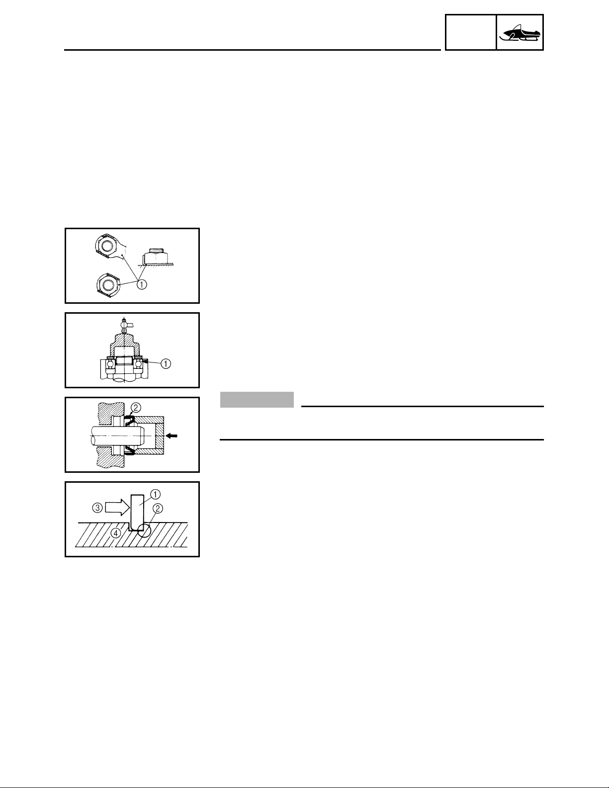
LOCK WASHERS/PLATES AND COTTER PINS
All lock washers/plates 1 and cotter pins must be replaced if they are
removed. Lock tab(s) should be bent along the bolt or nut flat(s) after the
bolt or nut has been properly tightened.
INFO
BEARINGS AND OIL SEALS
Install the bearings 1 and oil seals 2 with their manufacturer’s marks or
numbers facing outwards. (In other words, the stamped letters must be on
the side exposed to view.) When installing oil seals, apply a light coating
of lightweight lithium base grease to the seal lips. Oil the bearings liberally
when installing.
CAUTION:
Do not use compressed air to spin the bearings dry. This causes
damage to the surface of the bearings.
CIRCLIPS
All circlips should be inspected carefully before reassembly. Always
replace piston pin clips after one use. Replace misshapen circlips. When
installing a circlip 1, make sure that the sharp edged corner 2 is positioned opposite to the thrust 3 it receives. See the sectional view.
Shaft
4
LOCTITE
After installing fasteners that have LOCTITE® applied, wait 24 hours
before using the machine. This will give the LOCTITE
erly.
®
®
time to dry prop-
1-3
Page 13

GEN
SPECIAL TOOLS
SPECIAL TOOLS
Some special tools are necessary for a completely accurate tune-up and
assembly. Using the correct special tool will help prevent damage that can
be caused by the use of improper tools or improvised techniques.
NOTE:
• Be sure to use the correct part number when ordering the tool, since the
part number may differ according to country.
• For USA and Canada, use part number starting with “YB-”, “YM-”, “YU-”
or “YS-”.
• For others, use part number starting with “90890-”.
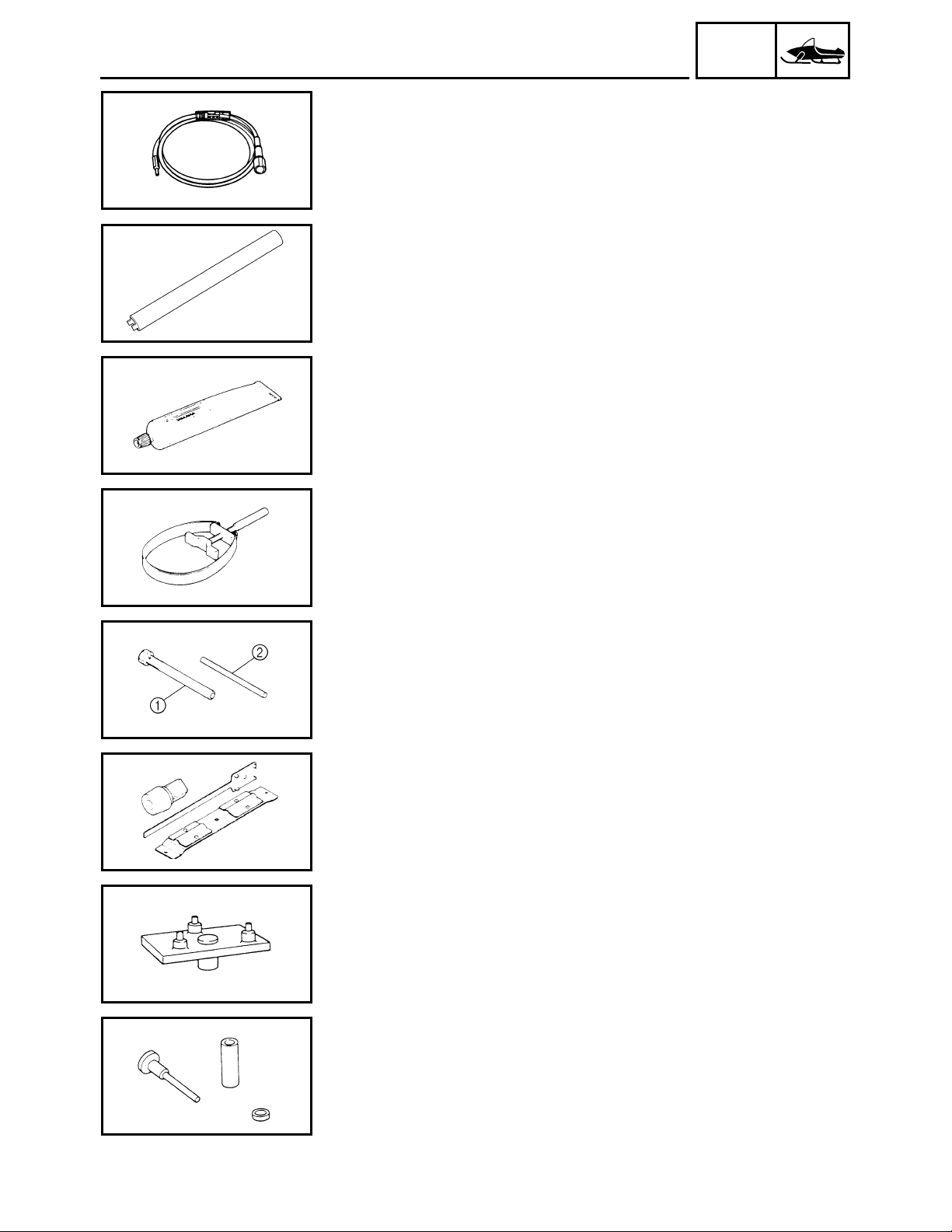
FOR TUNE UP
• Dial gauge
P/N: YU-03097
90890-03097
This gauge is used for run out measurement.
INFO
• Angle gauge
Use goods on the market.
This tool is used to tightening the torque.
• Steering linkage alignment plate
P/N: YS-01515
90890-01515
Locks steering relay arm and pivot arm shaft in place while adjusting the
steering linkage for front-end alignment.
FOR ENGINE SERVICE
• Piston pin puller
P/N: YU-01304
90890-01304
This tool is used to remove the piston pin.
• Rotor holding puller
P/N: YU-33270-B
90890-01362
• Flywheel puller attachment
P/N: YM-33282
90890-04089
These tools are used to remove the magneto rotor.
1-4
Page 14

GEN
SPECIAL TOOLS
• Cooling system tester
P/N: YU-24460-01
90890-01325
• Adapter
P/N: YU-33984
90890-01352
This tester and its adapter are used for checking the cooling system.
• Oil filter wrench
P/N: YM-01469
90890-01469
This tool is needed to loosen or tighten the oil filter cartridge.
INFO
• Vacuum gauge
P/N: YU-44456
90890-03094
This guide is used to synchronize the carburetors.
• Compression gauge
P/N: YU-33223 (compression gage)
90890-03081
These tools are used to measure engine compression.
• Valve spring compressor
P/N: YM-04019
90890-04019
• Valve spring compressor attachment
P/N: YM-04108
90890-04108
P/N: YM-04114
90890-04114
These tools are used to remove or install the valve assemblies.
1-5
Page 15

SPECIAL TOOLS
• 40 and 50 mm bearing driver
P/N: YM-04058
90890-04058
• Mechanical seal installer
P/N: YM-04145
90890-04145
These tools are used to install the water pump seal.
• Rotor holding tool
P/N: YU-01235
90890-01235
This tool is used to hold the camshaft sprocket.
GEN
INFO
• Valve guide remover (ø4)
P/N: YM-04111
90890-04111
This tool is used to remove or install the valve guides.
• Valve guide installer (ø4)
P/N: YM-04112
90890-04112
This tool is used to install the valve guides.
• Valve guide reamer (ø4)
P/N: YM-04113
90890-04113
This tool is used to rebore the new valve guides.
• Valve lapper
P/N: 90890-04101
This tool is needed to remove and install the valve lifters.
• Piston ring compressor
P/N: YM-08037
90890-05158
This tool is used to compress the piston rings when installing the piston
into the cylinder.
1-6
Page 16
GEN
SPECIAL TOOLS
• Dynamic spark tester
P/N: YM-34487
• Ignition checker
P/N: 90890-06754
This tool is used to check the ignition system component.
• Engine mount spacer wrench
P/N: YS-01516
90890-01516
Used to turn the engine mounting bolts when removing/installing engine.
• Yamaha bond No. 1215
P/N: 90890-85505
(Three Bond No.1215
This bond is used to seal two mating surfaces (e.g., crankcase mating surfaces.)
®
)
INFO
FOR POWER TRAIN SERVICE
• Sheave holder
P/N: YS-01880-A
90890-01701
This tool is used to hold the primary sheave and A.C. magneto rotor.
• Primary sheave puller (18 mm)
P/N: YS-01881-A 1, YS-01881-1 2
90890-01898
This tool is used for removing the primary sheave.
• Clutch spider separator
P/N: YS-28890-C
90890-01711
This tool is used when disassembling and assembling the primary sheave.
• Clutch separator adapter
P/N: YS-34480
90890-01740
This tool is used when disassembling and assembling the primary sheave.
• YXR clutch bushing jig kit
P/N: YS-39752
This tool is used for removal and installation of primary clutch weight and
roller bushings.
1-7
Page 17
GEN
SPECIAL TOOLS
• Clutch bushing press
P/N: YS-42424
This tool is used for removing and installing the post bushings (primary
sheave cap bush, sliding sheave bush and torque cam bush).
• Track clip installer
P/N: YS-91045-C
90890-01721
This tool is used for installing the track clip.
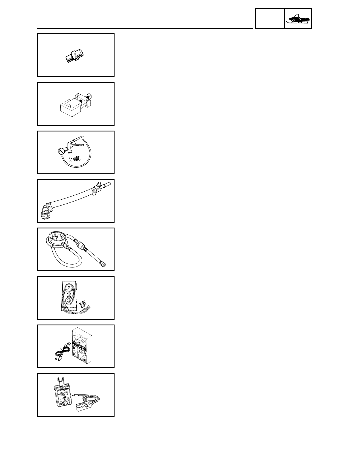
FOR FUEL INJECTION SERVICE
• Mity vac
P/N: YS-42423
90890-06756
This tool is used to measure the vacuum pressure.
INFO
• Fuel pressure adapter
P/N: YM-03176
90890-03176
This tool is needed to measure fuel pressure.
• Pressure gauge
P/N: YU-03153
90890-03153
This tool is used to measure fuel pressure.
• Vacuum gauge
P/N: YU-08030
90890-03094
This guide is used to synchronize the throttle bodies.
FOR ELECTRICAL SERVICE
• Pocket tester
P/N: YU-03112-C
90890-03112
This instrument is necessary for checking the electrical components.
• Engine tachometer
P/N: YU-08036-C
90793-80009
This tool is used to check engine speed.
1-8
Page 18

GEN
SPECIAL TOOLS
• Digital circuit tester
P/N: YU-A1927
90890-03174
This instrument is necessary for checking the electrical componenets.
INFO
1-9
Page 19
INSP
ADJ
INTRODUCTION/PERIODIC MAINTENANCE CHART FOR
THE EMISSION CONTROL SYSTEM
PERIODIC INSPECTION AND ADJUSTMENT
INTRODUCTION
This chapter includes all information necessary to perform recommended inspections and adjustments. These
preventive maintenance procedures, if followed, will ensure more reliable machine operation and a longer service life. In addition, the need for costly overhaul work will be greatly reduced. This information applies to
machines already in service as well as new machines that are being prepared for sale. All service technicians
should be familiar with this entire chapter.
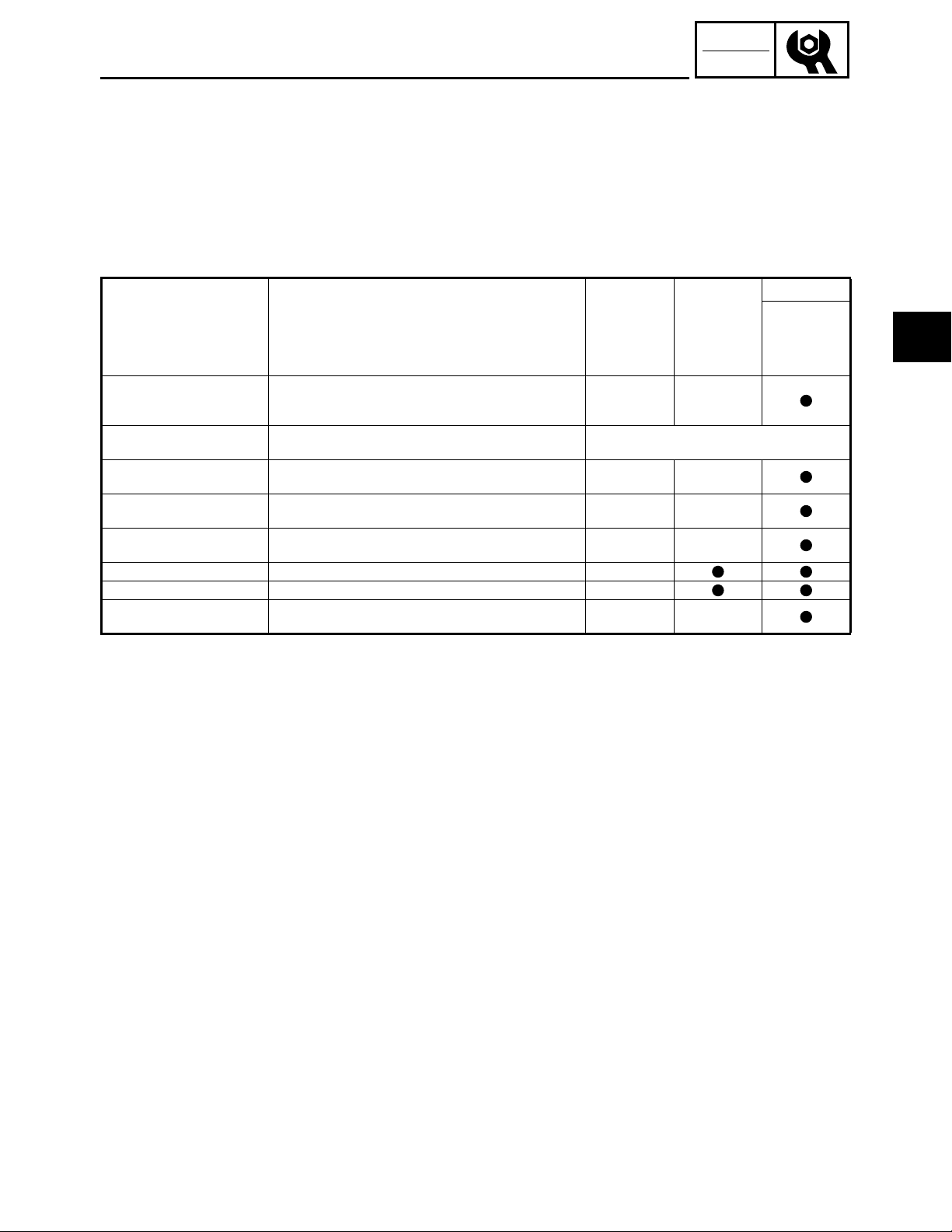
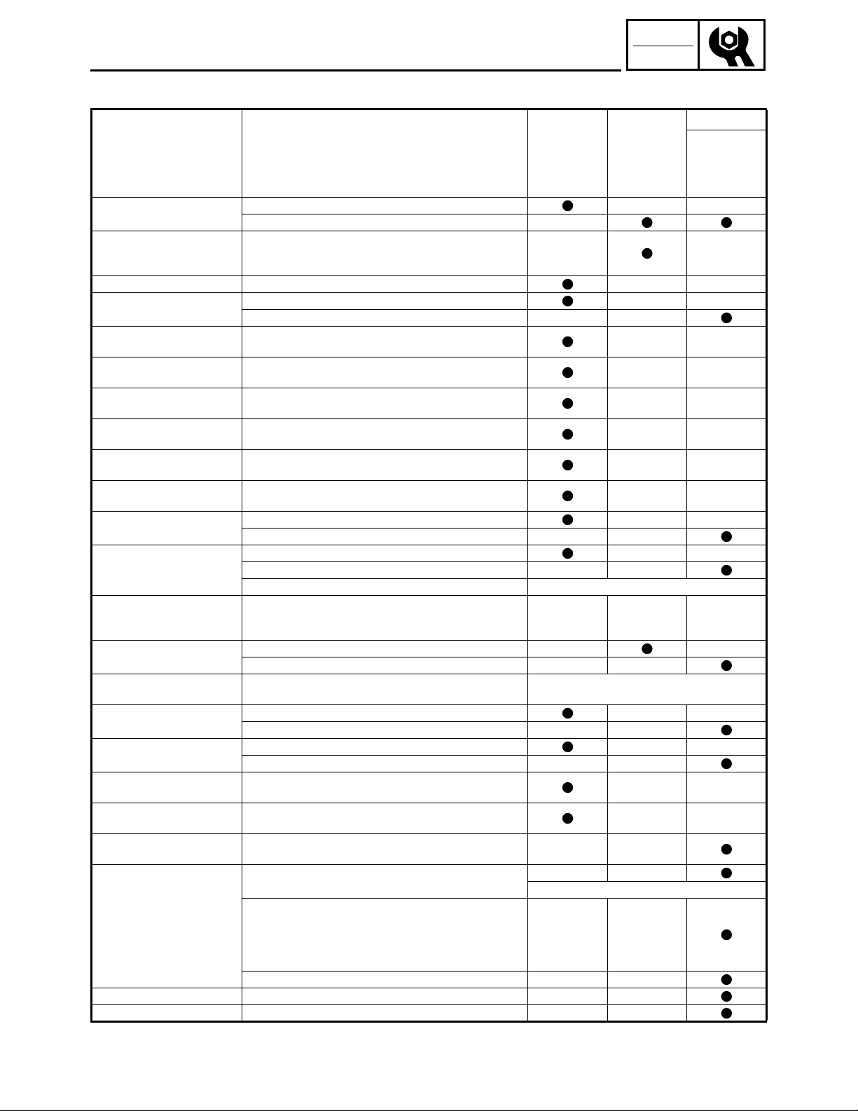
PERIODIC MAINTENANCE CHART FOR THE EMISSION CONTROL SYSTEM
Item Remarks
Spark plugs
∗
Valve clearance
∗
Crankcase breather system
∗
Fuel filter
∗
Fuel line
∗
Idle speed Check and adjust engine idle speed.
∗
Fuel injection Adjust synchronization.
∗
Exhaust system
∗
It is recommended that these items be serviced by a Yamaha dealer.
Check condition.
Adjust gap and clean.
Replace if necessary.
Check clearance.
Adjust clearance when engine is cold.
Check breather hose for cracks or damage.
Replace if necessary.
Check condition.
Replace if necessary.
Check fuel hose for cracks or damage.
Replace if necessary.
Check for leakage.
Tighten or replace gasket if necessary.
Initial
Pre-opera-
tion check
(Daily)
Every 40,000 km (25,000 mi)
1 month or
800 km
(500 mi)
(40 hr)
Every
Seasonally
or 4,000 km
(2,500 mi)
(200 hr)
2
2-1
Page 20
INSP
ADJ
GENERAL MAINTENANCE AND LUBRICATION CHART
GENERAL MAINTENANCE AND LUBRICATION CHART
Item Remarks
Engine oil
∗
Engine oil filter cartridge Replace.
Fuel Check fuel level.
Engine coolant
Throttle lever (handlebar
side)
Throttle override system
(T.O.R.S.)
Engine stop switch
Drive guard
V-belt
Drive track and idler wheels
Slide runners
Brake and parking brake
∗
Disc brake installation
Drive chain oil
Drive chain
Skis and ski runners
Steering system
Strap (PZ50M)
Lights
∗
Battery
∗
Primary and secondary
clutches
∗
Steering column bearing Lubricate with specified grease.
∗
Ski and front suspension Lubricate with specified grease.
∗
It is recommended that these items be serviced by a Yamaha dealer.
Check oil level.
∗
Replace.
Check coolant level.
∗
Air bleed the cooling system if necessary.
Check operation.
∗
Repair if necessary.
Check operation.
∗
Repair if necessary.
Check operation.
∗
Repair if necessary.
Check for cracks, bends or damage.
∗
Replace if necessary.
Check for wear and damage.
Replace if necessary.
Check deflection, and for wear and damage.
∗
Adjust/replace if necessary.
Check for wear and damage.
∗
Replace if necessary.
Check operation and fluid leakage.
∗
Adjust free play and/or replace pads if necessary.
∗
Replace brake fluid. See NOTE on page 2-3.
Check for slight free play.
Lubricate shaft with specified grease as required.
Check oil level.
∗
Replace.
Check deflection.
∗
Adjust if necessary.
Check for wear and damage.
∗
Replace if necessary.
Check operation.
∗
Adjust toe-out if necessary.
Check for damage.
∗
Replace if necessary.
Check operation.
Replace bulbs if necessary.
Check condition.
Charge if necessary.
Check engagement and shift speed.
Adjust if necessary.
Inspect sheaves for wear/damage.
Inspect weights/rollers and bushings for wear-for primary.
Inspect ramp shoes/bushings for wear-for secondary.
Replace if necessary.
Lubricate with specified grease.
Initial
Pre-opera-
tion check
(Daily)
1 month or
800 km
(500 mi)
(40 hr)
Initial at 500 km (300 mi) and every 800 km
(500 mi) thereafter.
Whenever operating elevation is changed.
Every
Seasonally
or 4,000 km
(2,500 mi)
(200 hr)
Every
20,000 km
(12,000 mi)
Every
1,600 km
(1,000 mi)
2-2
Page 21

INSP
ADJ
GENERAL MAINTENANCE AND LUBRICATION CHART
Every
Seasonally
or 4,000 km
(2,500 mi)
(200 hr)
Item Remarks
∗
Suspension component Lubricate with specified grease.
∗
Parking brake cable end
and lever end/throttle cable
end
Shroud and covers
Fittings and fasteners
Tool kit and recommended
equipment
∗
It is recommended that these items be serviced by a Yamaha dealer.
NOTE:
@
Lubricate with specified grease.
Check cable damage.
Replace if necessary.
Make sure that the shroud and covers are securely fas-
tened.
Check tightness.
∗
Repair if necessary.
Check for proper placement.
Pre-opera-
tion check
(Daily)
Initial
1 month or
800 km
(500 mi)
(40 hr)
Brake system:
• After disassembling the master cylinder or caliper cylinder, always change the brake fluid. Regularly check
the brake fluid level and add fluid if necessary.
• Replace the oil seals of the master cylinder and caliper cylinder every two years.
• Replace the brake hose every four years, or if cracked or damaged.
2-3
Page 22

INSP
ADJ
SPARK PLUGS/FUEL LINE INSPECTION
ENGINE
SPARK PLUGS
1. Remove:
• Fuel tank
Refer to “SEAT AND FUEL TANK” in CHAPTER 5. (PZ50/PZ50GT/PZ50FX/PZ50M)
Refer to “RIDER SEAT AND FUEL TANK” in
CHAPTER 5. (PZ50VT/PZ50MP)
2. Remove:
• Spark plug caps
• Spark plugs
3. Inspect:
• Electrodes 1
Damage/wear → Replace the spark plug.
• Insulator color 2
Abnormal color → Replace the spark plug
Normal color is medium-to-light tan.
4. Measure:
• Spark plug gap a
Out of specification → Regap.
Use a wire thickness gauge.
1
Spark plug gap:
0.6 ~ 0.7 mm (0.024 ~ 0.028 in)
If necessary, clean the spark plugs with a spark
plug cleaner.
Standard spark plug:
NGK R CR9EKB (NGK)
Before installing a spark plug, clean the gasket surface and spark plug surface.
5. Install:
• Spark plugs
Spark plug:
13 Nm (1.3 m · kg, 9.4 ft · lb)
T
.
R
.
NOTE:
Finger-tighten a the spark plug before torquing
it to specification.
b
FUEL LINE INSPECTION
1. Remove:
• Headlight assembly (PZ50/PZ50GT/PZ50FX/
PZ50M)
Refer to “COWLINGS” in CHAPTER 3.
2. Inspect:
• Fuel hose 1
• Fuel return hose
Cracks/damage → Replace.
2-4
Page 23
INSP
ADJ
1
COOLING SYSTEM
COOLING SYSTEM
Coolant replacement
NOTE:
The coolant should be changed at least every season.
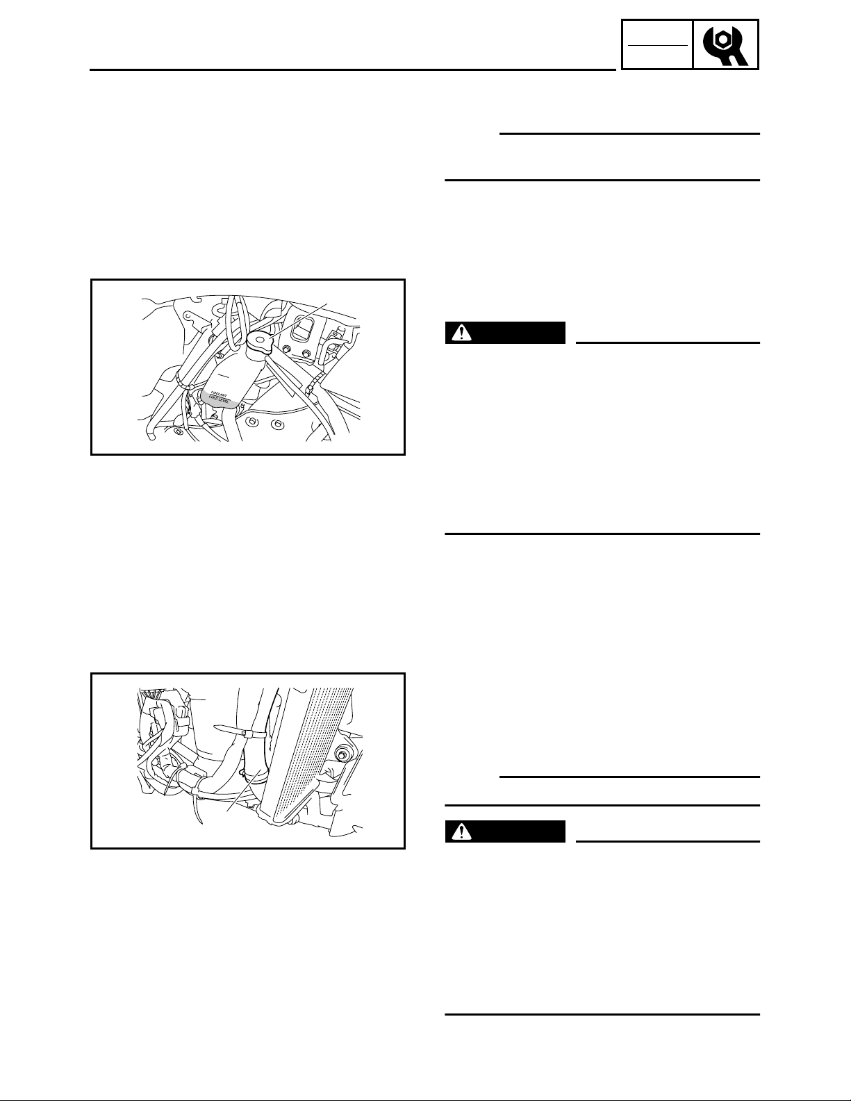
1. Place the machine on a level surface.
2. Remove:
• Right side panel
• Right side cover
Refer to “COWLINGS” in CHAPTER 3.
3. Remove:
• Coolant filler cap 1
WARNING
Do not remove the coolant filler cap 1 when the
engine is hot. Pressurized scalding hot fluid
and steam may be blown out, which could
cause serious injury. When the engine has
cooled, place a thick rag or a towel over the
coolant filler cap. Slowly turn the cap counterclockwise until it stop. This allows any residual
pressure to escape. When the hissing sound
has stopped, press down on the cap while turning it counterclockwise to remove it.
4. Place an open container under the radiator outlet hose 1.
5. Disconnect:
• Radiator outlet hose 1 1
6. Drain the coolant.
NOTE:
Lift up the tail of the machine to drain the coolant.
1
WARNING
Coolant is poisonous. It is harmful or fatal if
swallowed.
• If coolant is swallowed, induce vomiting
immediately and get immediate medical attention.
• If coolant splashes in your eyes, thoroughly
wash them with water and consult a doctor.
• If coolant splashes on your skin or clothes,
quickly wash it away with soap and water.
2-5
Page 24
INSP
ADJ
COOLING SYSTEM
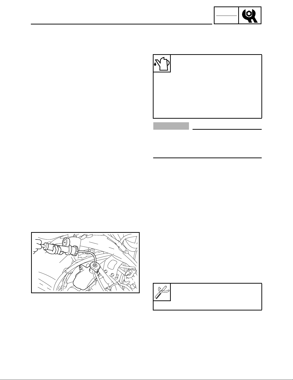
7. Connect:
• Radiator outlet hose 1
8. Fill:
• Cooling system
Recommended coolant:
High quality silicate-free ethylene
glycol antifreeze containing corrosion inhibitors
Coolant mixing ratio (coolant:water):
3:2 (60%:40%)
Total amount:
PZ50/PZ50GT/PZ50FX/PZ50M
3.6 L (3.17 Imp qt, 3.81 US qt)
PZ50VT/PZ50MP
3.7 L (3.26 Imp qt, 3.91 US qt)
CAUTION:
• Hard water or salt water is harmful to engine
parts. If soft water is not available, use boiled
or distilled water.
• Do not use water containing impurities or oil.
1
3
2
9. Bleed the air from the cooling system.
10. Inspect:
• Cooling system
Decrease of pressure (leaks) → Repair as
required.
Inspection steps:
• Attach the cooling system tester 1 and adapter
to the coolant filler 3.
2
Cooling system tester:
90890-01325, YU-24460-01
Adapter:
90890-01352, YU-33984
• Apply 100 kPa (1.0 kg/cm
• Measure the pressure with the gauge.
2-6
2
, 14 psi).
Page 25
INSP
ADJ
COOLING SYSTEM/VALVE CLEARANCE ADJUSTMENT
1
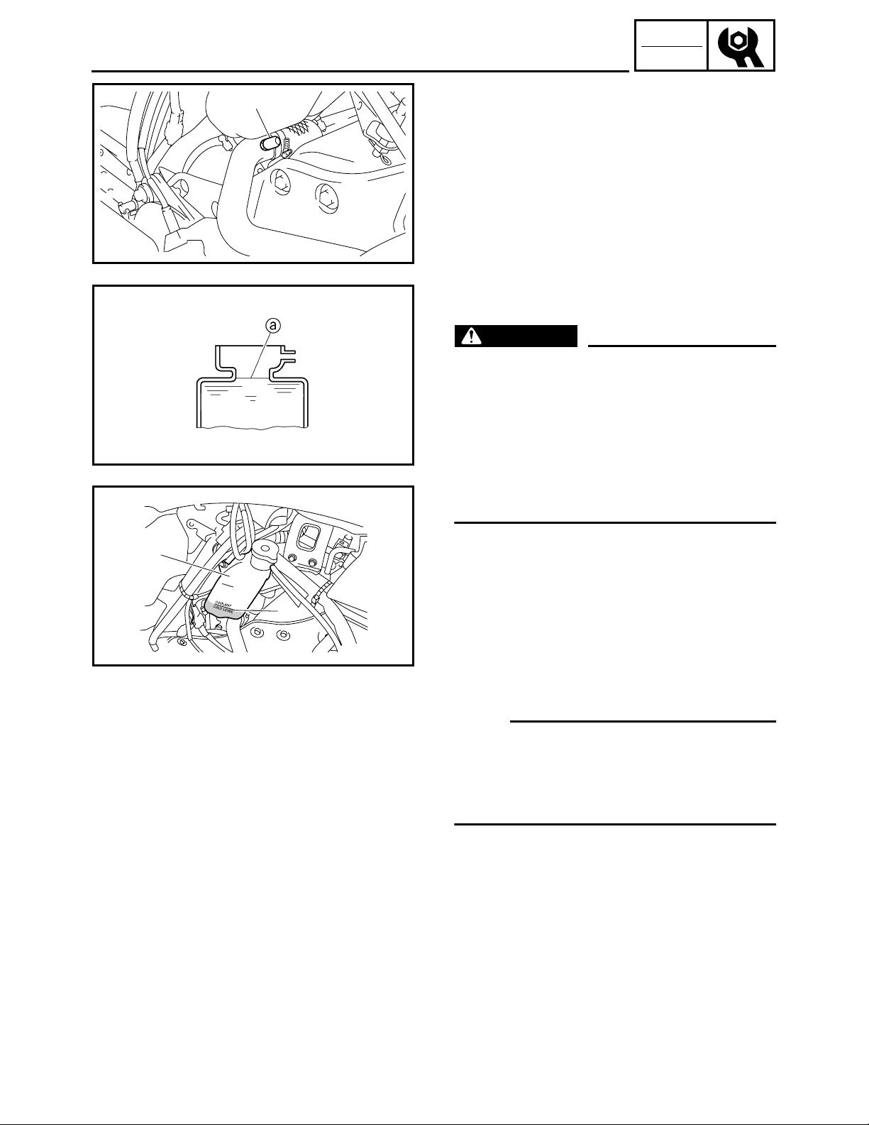
Air bleeding steps:
• Remove the cap 1 on the radiator outlet pipe 1.
• While slowly adding coolant to the coolant filler,
drain the coolant until no more air bubbles
appear.
• Install the cap 1.
• Add coolant to the full level a.
• Install the coolant filler cap.
Apply and lock the parking brake. Start the
engine and run it at approximately 1,700 ~
3,500 r/min until the coolant circulates (approximately 3 ~ 5 minutes). The heat exchanger will
be warm to the touch.
WARNING
To avoid severe injury or death:
• Make sure the machine is securely supported
with a suitable stand.
• Do not exceed 3,500 r/min. Drive line damage
and excessive V-belt wear could occur, or the
machine could unexpectedly move forward if
the clutch engages.
• Operate the engine only in a well-ventilated
area.
2
b
• Remove the coolant filler cap and bleed the
cooling system again, as described above.
No air bubbles → OK.
• Pour coolant into the coolant reservoir 2 until
the coolant level reaches the “COLD LEVEL”
mark b.
VALVE CLEARANCE ADJUSTMENT
NOTE:
• Valve clearance adjustment should be made on a
cold engine, at room temperature.
• When the valve clearance is to be measured or
adjusted, the piston must be at the top dead center (TDC) on the compression stroke.
1. Drain:
• Engine oil
Refer to “ENGINE OIL REPLACEMENT”.
2. Remove:
• Fuel tank
Refer to “SEAT AND FUEL TANK” in CHAPTER 5. (PZ50/PZ50GT/PZ50FX/PZ50M)
Refer to “RIDER SEAT AND FUEL TANK” in
CHAPTER 5. (PZ50VT/PZ50MP)
• Oil tank
Refer to “A.C. MAGNETO ROTOR AND
STARTER CLUTCH” in CHAPTER 5.
2-7
Page 26

INSP
ADJ
b
1
2
a
VALVE CLEARANCE ADJUSTMENT
3. Remove:
• Cylinder head cover
Refer to “CAMSHAFTS” in CHAPTER 5.
• Timing mark accessing screw 1
• Crankshaft end accessing screw 2
4. Measure:
• Valve clearance
Out of specification → Adjust.
Valve clearance (cold):
Intake valve:
0.11 ~ 0.20 mm
(0.0043 ~ 0.0079 in)
Exhaust valve:
0.21 ~ 0.25 mm
(0.0083 ~ 0.0098 in)
Checking steps:
• Turn the crankshaft counterclockwise.
• When piston #1 is at TDC on the compression
stroke, align the TDC mark a on the A.C. magneto rotor with the mark b on the A.C. magneto
cover.
1
NOTE:
TDC on the compression stroke can be found when
the camshaft lobes are turned away from each
other.
• Measure the valve clearance with a thickness
gauge 1.
NOTE:
• If the valve clearance is incorrect, record the
measured reading.
• Measure the valve clearance in the following
sequence.
Valve clearance measuring sequence
Cylinder #1 → #2
• Turn the crankshaft 180° counterclockwise and
check the valve clearance of piston #2.
Front
È
2-8
Page 27
INSP
ADJ
VALVE CLEARANCE ADJUSTMENT
5. Remove:
• Intake camshaft
• Exhaust camshaft
NOTE:
• Refer to “CAMSHAFTS” in CHAPTER 5.
• When removing the timing chain and camshafts,
fasten a wire to the timing chain to retrieve it if it
falls into the crankcase.
6. Adjust:
• Valve clearance
Adjustment steps:
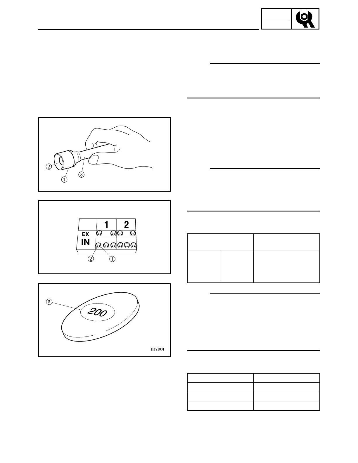
• Remove the valve lifter 1 and the valve pad
with a valve lapper 3.
NOTE:
• Cover the timing chain opening with a rag to prevent the valve pad from falling into the crankcase.
• Make a note of the position of each valve lifter
and valve pad 2 so that they can be installed in
the correct place.
2
1
• Select the proper valve pad from the following
table.
Valve pad thickness
range
1.20 ~
Nos.
120 ~ 240
2.40 mm
(0.047 ~
0.094 in)
Available valve pads
25 thicknesses in
0.05 mm (0.0020 in)
increments
NOTE:
• The thickness a of each valve pad is marked in
hundredths of millimeters on the side that
touches the valve lifter.
• Since valve pads of various sizes are originally
installed, the valve pad number must be rounded
in order to reach the closest equivalent to the
original.
• Round off the original valve pad number
according to the following table.
Last digit Rounded value
0 or 2 0
55
810
2-9
Page 28

INSP
ADJ
VALVE CLEARANCE ADJUSTMENT
EXAMPLE:
Original valve pad number = 148 (thickness =
1.48 mm (0.058 in))
Rounded value = 150
• Locate the rounded number of the original valve
pad and the measured valve clearance in the
valve pad selection table. The point where the
column and row intersect is the new valve pad
number.
NOTE:
The new valve pad number is only an approximation. The valve clearance must be measured again
and the above steps should be repeated if the measurement is still incorrect.
2-10
Page 29
INSP
ADJ
VALVE CLEARANCE ADJUSTMENT
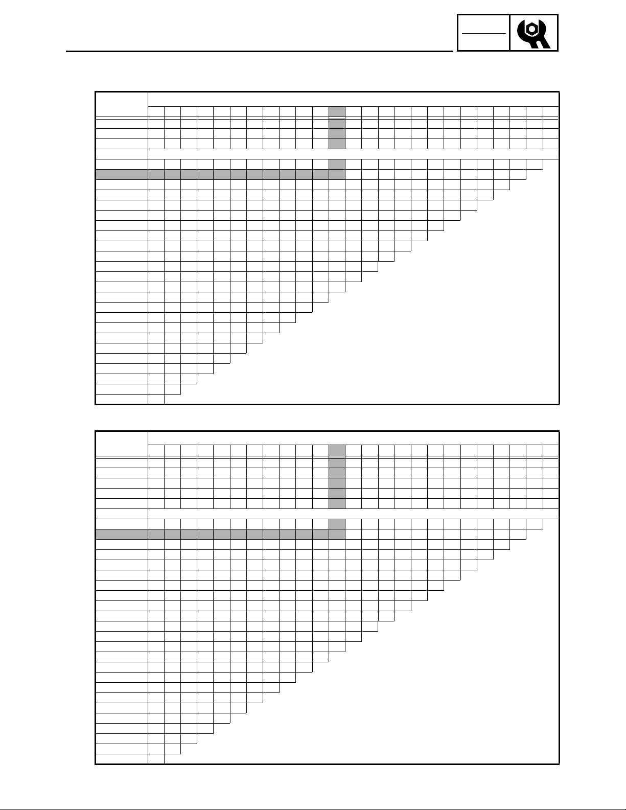
VALVE PAD SELECTION TABLE
INTAKE
Measured
clearance
0.00 ~ 0.02 120 125 130 135 140 145 150 155 160 165 170 175 180 185 190 195 200 205 210 215 220 225
0.03 ~ 0.07 120 125 130 135 140 145 150 155 160 165 170 175 180 185 190 195 200 205 210 215 220 225 230
0.08 ~ 0.10 120 125 130 135 140 145 150 155 160 165 170 175 180 185 190 195 200 205 210 215 220 225 230 235
0.11 ~ 0.20 Specification
exa 0.21 ~ 0.25 125 130 135 140 145 150 155 160 165 170 175 180 185 190 195 200 205 210 215 220 225 230 235 240
→
0.26 ~ 0.30 130 135 140 145 150 155 160 165 170 175 180 185 190 195 200 205 210 215 220 225 230 235 240
0.31 ~ 0.35 135 140 145 150 155 160 165 170 175 180 185 190 195 200 205 210 215 220 225 230 235 240
0.36 ~ 0.40 140 145 150 155 160 165 170 175 180 185 190 195 200 205 210 215 220 225 230 235 240
0.41 ~ 0.45 145 150 155 160 165 170 175 180 185 190 195 200 205 210 215 220 225 230 235 240
0.46 ~ 0.50 150 155 160 165 170 175 180 185 190 195 200 205 210 215 220 225 230 235 240
0.51 ~ 0.55 155 160 165 170 175 180 185 190 195 200 205 210 215 220 225 230 235 240
0.56 ~ 0.60 160 165 170 175 180 185 190 195 200 205 210 215 220 225 230 235 240
0.61 ~ 0.65 165 170 175 180 185 190 195 200 205 210 215 220 225 230 235 240
0.66 ~ 0.70 170 175 180 185 190 195 200 205 210 215 220 225 230 235 240
0.71 ~ 0.75 175 180 185 190 195 200 205 210 215 220 225 230 235 240
0.76 ~ 0.80 180 185 190 195 200 205 210 215 220 225 230 235 240
0.81 ~ 0.85 185 190 195 200 205 210 215 220 225 230 235 240
0.86 ~ 0.90 190 195 200 205 210 215 220 225 230 235 240
0.91 ~ 0.95 195 200 205 210 215 220 225 230 235 240
0.96 ~ 1.00 200 205 210 215 220 225 230 235 240
1.01 ~ 1.05 205 210 215 220 225 230 235 240 EXAMPLE:
1.06 ~ 1.10 210 215 220 225 230 235 240
1.11 ~ 1.15 215 220 225 230 235 240
1.16 ~ 1.20 220 225 230 235 240
1.21 ~ 1.25 225 230 235 240
1.26 ~ 1.30 230 235 240
1.31 ~ 1.35 235 240
1.36 ~ 1.40 240
120 125 130 135 140 145 150 155 160 165 170 175 180 185 190 195 200 205 210 215 220 225 230 235 240
↓
INSTALLED PAD NUMBER
VALVE CLEARANCE:
0.11 ~ 0.20 mm (0.0043 ~ 0.0079 in)
Installed is 175
Measured clearance is 0.27 mm (0.0106 in)
Replace 175 pad with 185 pad
EXHAUST
Measured
clearance
0.00 ~ 0.02 120 125 130 135 140 145 150 155 160 165 170 175 180 185 190 195 200 205 210 215
0.03 ~ 0.07 120 125 130 135 140 145 150 155 160 165 170 175 180 185 190 195 200 205 210 215 220
0.08 ~ 0.12 120 125 130 135 140 145 150 155 160 165 170 175 180 185 190 195 200 205 210 215 220 225
0.13 ~ 0.17 120 125 130 135 140 145 150 155 160 165 170 175 180 185 190 195 200 205 210 215 220 225 230
0.18 ~ 0.20 120 125 130 135 140 145 150 155 160 165 170 175 180 185 190 195 200 205 210 215 220 225 230 235
0.21 ~ 0.25 Specification
exa 0.26 ~ 0.30 125 130 135 140 145 150 155 160 165 170 175 180 185 190 195 200 205 210 215 220 225 230 235 240
→
0.31 ~ 0.35 130 135 140 145 150 155 160 165 170 175 180 185 190 195 200 205 210 215 220 225 230 235 240
0.36 ~ 0.40 135 140 145 150 155 160 165 170 175 180 185 190 195 200 205 210 215 220 225 230 235 240
0.41 ~ 0.45 140 145 150 155 160 165 170 175 180 185 190 195 200 205 210 215 220 225 230 235 240
0.46 ~ 0.50 145 150 155 160 165 170 175 180 185 190 195 200 205 210 215 220 225 230 235 240
0.51 ~ 0.55 150 155 160 165 170 175 180 185 190 195 200 205 210 215 220 225 230 235 240
0.56 ~ 0.60 155 160 165 170 175 180 185 190 195 200 205 210 215 220 225 230 235 240
0.61 ~ 0.65 160 165 170 175 180 185 190 195 200 205 210 215 220 225 230 235 240
0.66 ~ 0.70 165 170 175 180 185 190 195 200 205 210 215 220 225 230 235 240
0.71 ~ 0.75 170 175 180 185 190 195 200 205 210 215 220 225 230 235 240
0.76 ~ 0.80 175 180 185 190 195 200 205 210 215 220 225 230 235 240
0.81 ~ 0.85 180 185 190 195 200 205 210 215 220 225 230 235 240
0.86 ~ 0.90 185 190 195 200 205 210 215 220 225 230 235 240
0.91 ~ 0.95 190 195 200 205 210 215 220 225 230 235 240
0.96 ~ 1.00 195 200 205 210 215 220 225 230 235 240
1.01 ~ 1.05 200 205 210 215 220 225 230 235 240
1.06 ~ 1.10 205 210 215 220 225 230 235 240 EXAMPLE:
1.11 ~ 1.15 210 215 220 225 230 235 240
1.16 ~ 1.20 215 220 225 230 235 240
1.21 ~ 1.25 220 225 230 235 240
1.26 ~ 1.30 225 230 235 240
1.31 ~ 1.35 230 235 240
1.36 ~ 1.40 235 240
1.41 ~ 1.45 240
120 125 130 135 140 145 150 155 160 165 170 175 180 185 190 195 200 205 210 215 220 225 230 235 240
↓
INSTALLED PAD NUMBER
VALVE CLEARANCE:
0.21 ~ 0.25 mm (0.0083 ~ 0.0098 in)
Installed is 175
Measured clearance is 0.35 mm (0.0138 in)
Replace 175 pad with 185 pad
2-11
Page 30
INSP
ADJ
2
VALVE CLEARANCE ADJUSTMENT
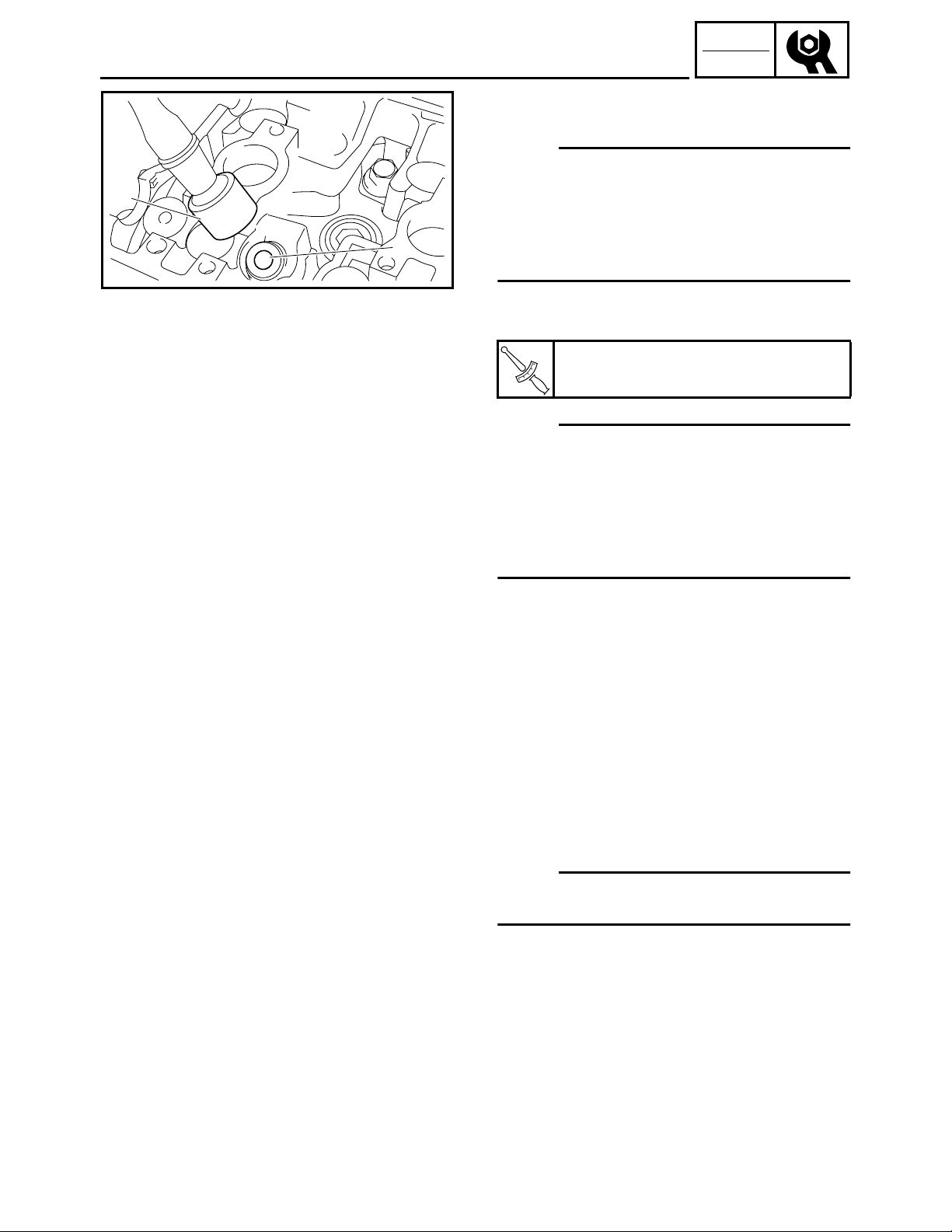
• Install the new valve pad 1 and the valve lifter
.
2
NOTE:
• Apply molybdenum disulfide oil to the valve pad
and the valve lifter.
• The valve lifter must turn smoothly when rotated
by hand.
1
• Install the valve lifter and the valve pad in the correct place.
• Install the exhaust and intake camshafts, timing
chain and camshaft caps.
Camshaft cap bolt:
9 Nm (0.9 m · kg, 6.5 ft · lb)
T
.
R
.
NOTE:
• Refer to “CAMSHAFTS” in CHAPTER 5.
• Lubricate the camshaft caps, camshaft lobes,
camshaft journals and camshaft cap bolts.
• Align the camshaft marks with the camshaft cap
marks.
• Rotate the crankshaft counterclockwise several
turns to seat the parts.
• Measure the valve clearance again.
• If the valve clearance is still out of specification,
repeat all of the valve clearance adjustment
steps until the specified clearance is obtained.
7. Install:
• Crankshaft end accessing screw
• Timing mark accessing screw
8. Install:
• Cylinder head cover
Refer to “CAMSHAFTS” in CHAPTER 5.
9. Install:
• All removed parts
NOTE:
For installation, reverse the removal procedure.
Note the following points.
2-12
Page 31

INSP
ADJ
THROTTLE BODY SYNCHRONIZATION
THROTTLE BODY SYNCHRONIZATION
NOTE:
Prior to synchronizing the throttle bodies, the valve
clearance and the engine idle speed should be
properly adjusted.
1. Remove:
• Headlight assembly (PZ50/PZ50GT/PZ50FX/
PZ50M)
• Air filter case assembly
Refer to “COWLINGS” in CHAPTER 3.
2. Remove:
• Vacuum cap 1
1
1
3. Install:
• Vacuum gauge 1
Vacuum gauge:
90890-03094, YU-44456
4. Install:
• Air filter case
Refer to “COWLINGS” in CHAPTER 3.
5. Start the engine and let it warm up for several
minutes.
6. Inspect:
• Engine idle speed
Out of specification
Refer to “ENGINE IDLE SPEED ADJUSTMENT”.
Engine idle speed:
1,700 ~ 1,900 r/min
7. Adjust:
• Throttle body synchronization
Adjust.
→
2-13
Page 32

INSP
ADJ
THROTTLE BODY SYNCHRONIZATION/
ENGINE IDLE SPEED ADJUSTMENT
Adjustment steps:
• Synchronize throttle body #1 and throttle body
#2 by turning the synchronizing screws 1 in
either direction until both gauges read the
same.
NOTE:
After each step, rev the engine two or three times,
each time for less than a second, and check the
1
synchronization again.
Vacuum pressure at engine idling
speed:
20.27 ~ 22.93 kPa
(0.20 ~ 0.23 kg/cm
NOTE:
The difference in vacuum pressure between two
throttle bodies should not exceed 1.33 kPa
(0.01 kg/cm
2
, 0.19 psi).
2
, 2.88 ~ 3.26 psi)
8. Measure:
• Engine idle speed
Out of specification → Adjust.
Make sure that the vacuum pressure is within
specification.
9. Stop the engine and remove the measuring
equipment.
10. Adjust:
• Throttle cable free play
Refer to “THROTTLE CABLE FREE PLAY
ADJUSTMENT”.
ENGINE IDLE SPEED ADJUSTMENT
NOTE:
Prior to adjusting the engine idling speed, the throttle body synchronization should be adjusted properly, the air filter should be clean, and the engine
should have adequate compression.
1. Start the engine and let it warm up for several
minutes.
2. Measure:
• Engine idle speed
Out of specification → Adjust.
Engine idle speed:
1,700 ~ 1,900 r/min
2-14
Page 33

INSP
ADJ
ENGINE IDLE SPEED ADJUSTMENT/
THROTTLE CABLE FREE PLAY ADJUSTMENT
3. Adjust:
• Engine idle speed
Adjustment steps:
• Remove the rubber cap 1.
• Turn the idle adjusting screw 2 in or out until
the specified engine idle speed is obtained.
1
Turning in → Idle speed is increased.
Turning out → Idle speed is decreased.
NOTE:
After adjusting the engine idle speed, the throttle
cable free play should be adjusted.
2
THROTTLE CABLE FREE PLAY
ADJUSTMENT
NOTE:
• Before adjusting the throttle cable free play, the
engine idle speed should be adjusted.
• Adjust the throttle cable free play while the cable
is in the cable guide.
a
2
1
1. Measure:
• Throttle cable free play
Out of specification → Adjust.
Throttle cable free play:
2.0 ~ 3.0 mm (0.08 ~ 0.12 in)
2. Adjust:
• Throttle cable free play
Throttle body side adjustment steps:
• Remove the air filter case.
Refer to “COWLINGS” in CHAPTER 3.
• Loosen the locknut 1.
• Turn the adjusting nut 2 in or out until the spec-
ified free play is obtained.
Turning in → Free play is increased.
Turning out → Free play is decreased.
2-15
a
Page 34

INSP
ADJ
THROTTLE CABLE FREE PLAY ADJUSTMENT/
THROTTLE OVERRIDE SYSTEM (T.O.R.S.) CHECK
• Tighten the locknut.
NOTE:
If the specified throttle cable free play cannot be
obtained on the throttle body side of the cable, use
the adjusting nut on the handlebar side. (PZ50/
PZ50GT/PZ50FX/PZ50M)
Handlebar side adjustment steps:
(PZ50/PZ50GT/PZ50FX/PZ50M)
• Loosen the locknut 1.
• Turn the adjusting nut 2 in or out until the spec-
2
1
ified free play is obtained.
Turning in → Free play is increased.
Turning out → Free play is decreased.
NOTE:
After adjusting the free play, turn the handlebar to
right and left, and make sure that the engine idling
does not run faster.
THROTTLE OVERRIDE SYSTEM (T.O.R.S.)
CHECK
WARNING
When checking T.O.R.S.:
• Be sure the parking brake is applied.
• Be sure the throttle lever moves smoothly.
• Do not run the engine up to the clutch
engagement speed. Otherwise, the machine
could start moving forward unexpectedly,
which could cause an accident.
1. Start the engine.
2. Hold the pivot point of the throttle lever away
from the throttle switch by putting your thumb
(above) and forefinger (below) between the
throttle lever pivot 1 and stop switch housing
.
2
While holding as described above, press the
throttle lever 3 gradually.
The T.O.R.S. will operate and the engine
should run between 2,800 and 3,000 r/min.
2-16
Page 35

INSP
ADJ
THROTTLE OVERRIDE SYSTEM (T.O.R.S.) CHECK/
COMPRESSION PRESSURE MEASUREMENT
WARNING
If the engine does not run between 2,800 and
3,000 r/min, stop the engine by turning the main
switch to the “OFF” position and check the
electrical system.
COMPRESSION PRESSURE
MEASUREMENT
NOTE:
Insufficient compression pressure will result in a
loss of performance.
1. Measure:
• Valve clearance
Out of specification → Adjust.
Refer to “VALVE CLEARANCE ADJUSTMENT”.
2. Start the engine, warm it up for several minutes,
and then turn it off.
3. Remove:
• Fuel tank
Refer to “SEAT AND FUEL TANK” in CHAPTER 5. (PZ50/PZ50GT/PZ50FX/PZ50M)
Refer to “RIDER SEAT AND FUEL TANK” in
CHAPTER 5. (PZ50VT/PZ50MP)
4. Remove:
• Spark plug
CAUTION:
Before removing the spark plugs, use compressed air to blow away any dirt accumulated
in the spark plug wells to prevent it from falling
into the cylinders.
5. Install:
• Compression gauge 1
1
Compression gauge:
90890-03081, YU-33223
2-17
Page 36

INSP
ADJ
COMPRESSION PRESSURE MEASUREMENT
6. Measure:
• Compression pressure
Above the maximum pressure → Inspect the
cylinder head, valve surfaces, and piston
crown for carbon deposits.
Below the minimum pressure → Squirt a few
drops of oil into the affected cylinder and
measure again.
Refer to the following table.
Compression pressure
(with oil applied into cylinder)
Reading Diagnosis
Higher than
without oil
Same as
without oil
Piston ring(-s) wear or
damage → Repair.
Piston, valves, cylinder
head gasket or piston
possibly defective →
Repair.
Compression pressure (at
sea level)
Compression pressure (at sea level):
Standard:
900 kPa (9.0 kg/cm
2
, 128.0 psi) at
400 r/min
Minimum:
700 kPa (7.0 kg/cm
2
, 99.5 psi) at
400 r/min
Maximum:
1,100 kPa (11.0 kg/cm
2
, 156.4 psi)
at 400 r/min
Measurement steps:
• Turn the main switch to “START”.
• With the throttle wide open, crank the engine
until the reading on the compression gauge stabilizes.
WARNING
To prevent sparking, ground all ignition coil
leads before cranking the engine.
NOTE:
The difference in compression pressure between
cylinders should not exceed 100 kPa (1 kg/cm
14.2 psi).
2
,
2-18
7. Install:
• Spark plug
T
.
R
.
Spark plug:
13 Nm (1.3 m · kg, 9.4 ft · lb)
Page 37

INSP
ADJ
1
ENGINE OIL LEVEL INSPECTION
ENGINE OIL LEVEL INSPECTION
1. Inspect:
• Engine oil level
CAUTION:
Do not run the engine with too much or not
enough oil in the oil tank. Oil could flow into the
air filter and the engine could be damaged.
Inspection steps:
• Place the snowmobile on a level surface and
apply the parking brake.
• Start the engine, warm it up for 10 ~ 15 minutes,
and then turn off.
• Remove the right side cover.
Refer to “COWLINGS” in CHAPTER 3.
• Disconnect the oil level switch coupler 1.
2
CAUTION:
Disconnect the oil level switch coupler before
removing the oil level gauge. Otherwise the
lead can twist and become severed.
• Remove the oil level gauge/dipstick 2, wipe it
clean, insert it back into the filler hole (without
screwing it in), and then remove it again to
check the oil level.
• The engine oil level should be between the
maximum level mark “H” a and minimum level
mark “L” b.
Below the minimum level mark → Add the recommended engine oil to the proper level.
CAUTION:
When adding the engine oil, be careful not to fill
above the maximum level mark and minimum
level mark on the oil level gauge.
Recommended oil:
Refer to the chart for the engine oil
grade which is best suited for certain atmospheric temperatures.
API standard:
API SE, SF, SG or higher
SAE 0W-30
CAUTION:
Do not allow foreign materials to enter the
crankcase.
NOTE:
Before checking the engine oil level, wait a few
minutes until the oil has settled.
2-19
Page 38

INSP
ADJ
ENGINE OIL LEVEL INSPECTION/
ENGINE OIL REPLACEMENT
• Start the engine, warm it up for several minutes,
and then turn it off.
• Check the engine oil level again.
NOTE:
Before checking the engine oil level, wait a few
minutes until the oil has settled.
CAUTION:
• Use only 4-stroke engine oil.
• Engine oil also lubricates the starter clutch. In
order to prevent clutch slippage, do not mix
any chemical additives with the oil or use oils
of a higher grade than “CD”. In addition, do
not use oils labeled “ENERGY CONSERVING
II” or higher.
1
ENGINE OIL REPLACEMENT
1. Place the snowmobile on a level surface and
apply the parking brake.
2. Start the engine, warm up for several minutes,
and then turn it off.
3. Place a containers under the engine oil pan and
oil tank.
4. Remove:
• Bottom panel 1
5. Remove:
• Left side panel
• Right side cover
• Right lower cover
Refer to “COWLINGS” in CHAPTER 3.
6. Disconnect:
• Oil level gauge coupler
Refer to “ENGINE OIL LEVEL INSPECTION”.
7. Remove:
• Oil level gauge/dipstick
Refer to “ENGINE OIL LEVEL INSPECTION”.
2-20
Page 39

INSP
ADJ
1
1
ENGINE OIL REPLACEMENT
8. Remove:
• Cylinder head cap 1
9. Remove:
• Oil pan engine oil drain bolt 1
1
1
1
10. Remove:
• Oil tank engine oil drain bolt 1
11. Drain:
• Engine oil
(completely from the oil pan and oil tank)
12. If the oil filter cartridge is also to be replaced,
perform the following procedure.
Replacement steps:
• Remove the air filter case.
Refer to “COWLINGS” in CHAPTER 3.
• Remove the oil filter bolts 1.
• Remove the oil filter cartridge
wrench 3.
Oil filter wrench:
90890-01469, YM-01469
2 with an oil filter
2
3
2-21
Page 40

INSP
ADJ
ENGINE OIL REPLACEMENT
4
• Apply a thin coat of engine oil onto the O-ring
4
of the new oil filter cartridge.
CAUTION:
Make sure that the O-ring 4 is positioned correctly in the groove of the oil filter cartridge.
• Tighten the new oil filter cartridge to specification with an oil filter wrench.
Oil filter cartridge:
17 Nm (1.7 m · kg, 12 ft · lb)
T
.
R
.
• Tighten the oil cooler bolts to specification.
Oil cooler bolt:
10 Nm (1.0 m · kg, 7.2 ft · lb)
T
.
R
.
LOCTITE
13. Install:
• Drain bolts
(along with the new gaskets)
Oil tank engine oil drain bolt:
16 Nm (1.6 m · kg, 11 ft · lb)
T
.
R
.
Oil pan engine oil drain bolt:
30 Nm (3.0 m · kg, 22 ft · lb)
®
14. Fill:
• Engine oil
(with the specified amount of the recommended engine oil)
Add 1.5 L (1.3 Imp qt, 1.6 US qt) of the recommended engine oil to the oil tank, and then
install and tighten the oil level gauge/dipstick
and the cylinder head cap.
Quantity:
Total amount:
3.00 L (2.64 Imp qt, 3.17 US qt)
Periodic oil change:
2.45 L (2.16 Imp qt, 2.59 US qt)
With oil filter replacement:
2.63 L (2.31 Imp qt, 2.78 US qt)
15. Inspect:
• Engine and oil tank
(for engine oil leaks)
16. Inspect:
• Engine oil level
Refer to “ENGINE OIL LEVEL INSPECTION”.
2-22
Page 41

INSP
ADJ
ENGINE OIL REPLACEMENT/CYLINDER HEAD BREATHER
HOSE INSPECTION/THROTTLE BODY JOINTS INSPECTION
17. Inspect:
• Engine oil pressure
1
Inspection steps:
• Remove the exhaust pipe joint upper cover.
Refer to “EXHAUST PIPE AND MUFFLER” in
CHAPTER 5.
• Slightly loosen the oil gallery bolt 1.
• Install the fuel tank.
Refer to “SEAT AND FUEL TANK” in CHAPTER 5. (PZ50/PZ50GT/PZ50FX/PZ50M)
Refer to “RIDER SEAT AND FUEL TANK” in
CHAPTER 5. (PZ50VT/PZ50MP)
• Start the engine and keep it idling until engine
oil starts to seep from the oil check bolt.
If no engine oil comes out after one minute, turn
the engine off so that it will not seize.
• Check the engine oil passages, the oil filter and
the oil pump for damage or leakage.
• Start the engine after solving the problem(-s)
and check the engine oil pressure again.
Tighten the oil check bolt to specification.
Oil check bolt:
10 Nm (1.0 m · kg, 7.2 ft · lb)
T
.
R
.
1
CYLINDER HEAD BREATHER HOSE
INSPECTION
1. Inspect:
• Cylinder head breather hose 1
Cracks/damage → Replace.
Loosen connection → Connect properly.
CAUTION:
Make sure that the cylinder head breather hose
is routed correctly.
THROTTLE BODY JOINTS INSPECTION
1. Remove:
• Air filter case
Refer to “COWLINGS” in CHAPTER 3.
2. Inspect:
• Throttle body joints 1
Cracks/damage → Replace.
Refer to “THROTTLE BODY” in CHAPTER 7.
1
2-23
Page 42

INSP
ADJ
CHECKING THE AIR FILTER ELEMENT
CHECKING THE AIR FILTER ELEMENT
1. Remove:
• Air filter case cover
Refer to “COWLINGS” in CHAPTER 3.
2. Lift up the air filter element frame and remove
the air filter element.
3. Clean:
• Air filter element
NOTE:
Remove the snow.
4. Inspect:
• Air filter element
Damage/clogs → Replace.
5. Install:
• Air filter element
• Air filter case cover
2-24
Page 43

INSP
ADJ
7
8
9
1
3
0
B
1
A
5
A
3
EXHAUST SYSTEM INSPECTION
EXHAUST SYSTEM INSPECTION
1. Remove:
• Fuel tank
Refer to “SEAT AND FUEL TANK” in CHAPTER 5. (PZ50/PZ50GT/PZ50FX/PZ50M)
Refer to “RIDER SEAT AND FUEL TANK” in
CHAPTER 5. (PZ50VT/PZ50MP)
2. Inspect:
• Exhaust pipe joints 1
• Exhaust pipe/muffler assembly 2
• Exhaust pipe bands 3
• Muffler end cover 4 (PZ50/PZ50GT/PZ50FX/
PZ50M)
• Muffler damper holder 5
• Muffler damper 6
Cracks/damage → Replace.
• Gasket 7
• Gaskets 8
Exhaust gas leaks → Replace.
3. Inspect:
• Tightening torque
6
5
6
4
C
2
Exhaust pipe joint bolt 9:
25 Nm (2.5 m · kg, 18 ft · lb)
T
.
R
.
Exhaust pipe/muffler bolt 0:
33 Nm (3.3 m · kg, 24 ft · lb)
Muffler damper holder bolt A:
10 Nm (1.0 m · kg, 7.2 ft · lb)
Exhaust pipe band bolt B:
18 Nm (1.8 m · kg, 13 ft · lb)
Muffler end cover bolt C:
10 Nm (1.0 m · kg, 7.2 ft · lb)
LOCTITE
4. Install:
• Fuel tank
Refer to “SEAT AND FUEL TANK” in CHAPTER 5. (PZ50/PZ50GT/PZ50FX/PZ50M)
Refer to “RIDER SEAT AND FUEL TANK” in
CHAPTER 5. (PZ50VT/PZ50MP)
®
2-25
Page 44

INSP
ADJ
SHEAVE OFFSET ADJUSTMENT
POWER TRAIN
SHEAVE OFFSET ADJUSTMENT
1. Remove:
• Left side panel
• Left side cover
Refer to “COWLINGS” in CHAPTER 3.
2. Remove:
• Drive V-belt
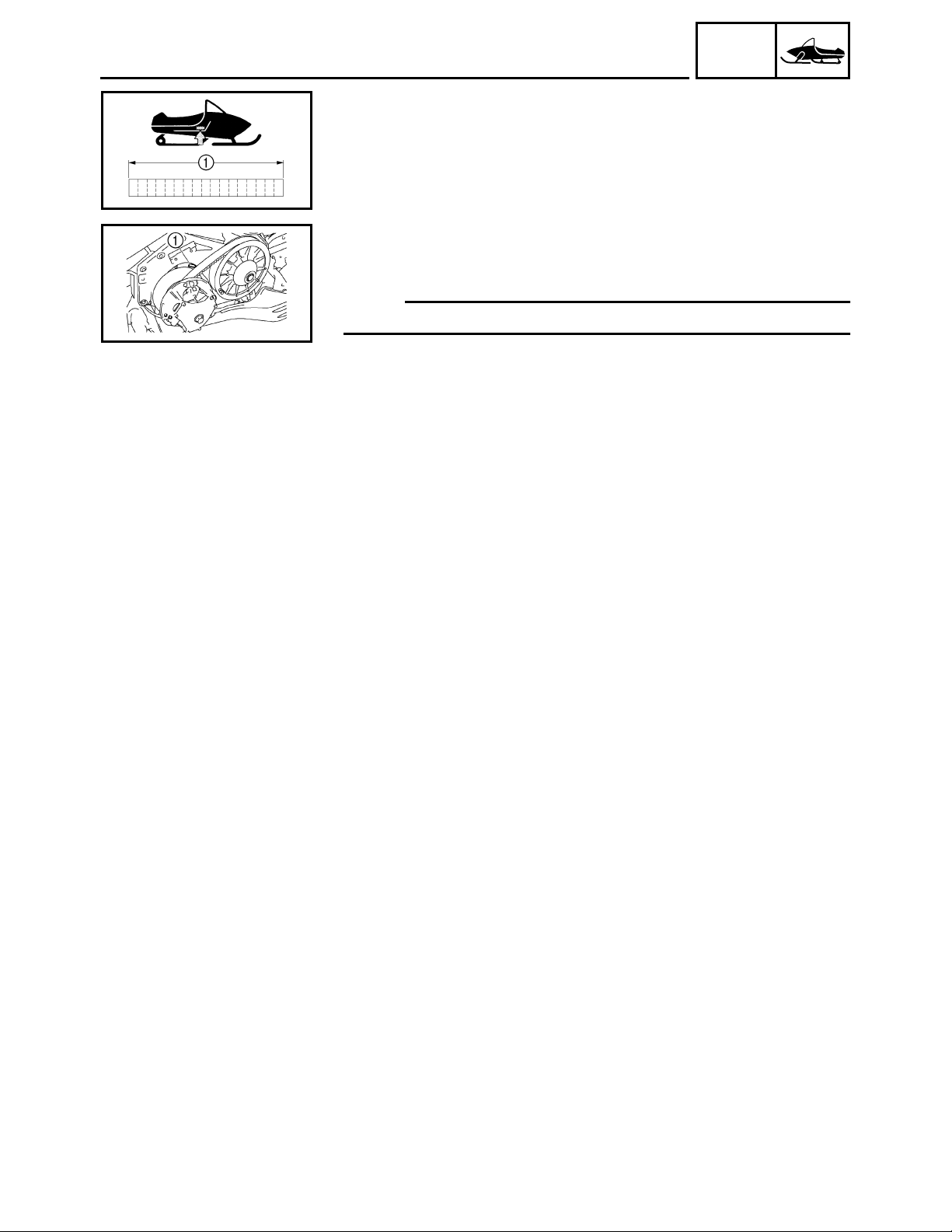
3. Measure:
• Sheave offset a
Use a straightedge that is approximately
470 mm (18.5 in) long, 20 mm (0.79 in) wide,
and 4 mm (0.16 in) thick.
Out of specification → Adjust.
Sheave offset:
14.5 ~ 17.5 mm (0.57 ~ 0.69 in)
NOTE:
Push the secondary sheave inward towards the
frame, and then measure the sheave offset.
4
3
1
2
4. Adjust:
• Sheave offset
Adjustment steps:
• Apply the brake to lock the secondary sheave.
• Remove the secondary sheave bolt 1, washer
, shim(s) (left), and secondary sheave 3.
2
• Install the appropriate shim(s) (right) 4 from the
following table so that the sheave offset is within
specification.
Shim size
Part number Thickness
90201-252F1 0.5 mm (0.02 in)
90201-25527 1.0 mm (0.04 in)
2-26
Page 45

INSP
ADJ
SHEAVE OFFSET ADJUSTMENT
• Install the secondary sheave, secondary
sheave bolt and washer.
Secondary sheave bolt:
60 Nm (6.0 m · kg, 43 ft · lb)
T
.
R
.
• Recheck the sheave offset. If out of specification, repeat the above steps.
NOTE:
When adjusting the sheave offset, the secondary
sheave free play (clearance) should be adjusted.
a
3
2
1
5. Measure:
• Secondary sheave free play (clearance) a
Use a feeler gauge.
Out of specification → Adjust.
Secondary sheave free play (clearance):
1.0 ~ 2.0 mm (0.04 ~ 0.08 in)
6. Adjust:
• Secondary sheave free play (clearance)
Adjustment steps:
• Apply the brake to lock the secondary sheave.
• Remove the secondary sheave bolt 1 and
washer 2.
• Install the appropriate shim(s) (left) 3 from the
following table so that the secondary sheave
free play is within specification.
Shim size
Part number Thickness
90201-252F1 0.5 mm (0.02 in)
90201-25527 1.0 mm (0.04 in)
2-27
Page 46

INSP
ADJ
a
a
DRIVE V-BELT
DRIVE V-BELT
WARNING
When installing the new V-belt, make sure that
it is positioned from 1.5 mm (0.06 in) above
the edge of the secondary sheave to –0.5 mm
(–0.02 in) below the edge a.
If the V-belt is not positioned correctly, the
clutch engagement speed will be changed. The
machine may move unexpectedly when the
engine is started.
New belt width:
34.1 mm (1.34 in)
Belt wear limit width:
32.5 mm (1.28 in)
1. Inspect:
• Drive V-belt
Cracks/damage/wear → Replace.
Oil or grease on the V-belt → Check the primary and secondary sheaves.
2. Inspect:
• Primary sheave
• Secondary sheave
Oil or grease on the primary and secondary
sheaves → Use a rag soaked in lacquer thinner or solvent to remove the oil or grease.
Check the primary and secondary sheaves.
3. Measure:
• Drive V-belt circumference a
Out of specification → Replace.
V-belt circumference:
1,132 ~ 1,138 mm (44.6 ~ 44.8 in)
2-28
Page 47

INSP
ADJ
ENGAGEMENT SPEED CHECK/
PARKING BRAKE ADJUSTMENT
ENGAGEMENT SPEED CHECK
1. Place the machine on a level surface of hardpacked snow.
2. Inspect:
• Clutch engagement speed
Inspection steps:
• Start the engine, and open the throttle lever
gradually.
• Check the engine speed when the machine
starts moving forward.
Out of specification → Adjust the primary
sheave.
Engagement speed:
PZ50/PZ50GT/PZ50FX:
3,700 ~ 4,100 r/min
PZ50M “USA/Canada”:
4,100 ~ 4,500 r/min
PZ50M “Europe”:
3,900 ~ 4,300 r/min
PZ50VT “USA/Canada”:
3,300 ~ 3,700 r/min
PZ50VT “Europe”/PZ50MP:
2,900 ~ 3,300 r/min
PARKING BRAKE ADJUSTMENT
1. Remove:
• Right side cover
Refer to “COWLINGS” in CHAPTER 3.
2. Measure:
• Parking brake cable distance
Out of specification → Adjust.
Parking brake cable distance:
43.5 ~ 46.5 mm (1.713 ~ 1.831 in)
2-29
Page 48

INSP
ADJ
2
1
PARKING BRAKE ADJUSTMENT/
BRAKE FLUID LEVEL INSPECTION
3. Adjust:
• Parking brake cable
a
Adjustment steps:
• Loosen the locknut 1.
• Turn the adjuster 2 in or out until the specified
distance a is obtained.
Turning in → Distance a is increased.
Turning out → Distance a is decreased.
• Tighten the locknut.
2
1
4. Measure:
• Brake pad clearance (a +
Out of specification → Adjust.
Brake pad clearance (a + b):
1.5 ~ 2.0 mm (0.059 ~ 0.079 in)
5. Adjust:
• Brake pad clearance
Adjustment steps:
• Loosen the locknut 1.
• Turn the adjuster 2 in or out until the specified
clearance between the brake pad 3 and brake
disc 4 is obtained.
• Tighten the locknut.
b)
BRAKE FLUID LEVEL INSPECTION
1. Place the machine on a level surface.
2. Check:
• Fluid level
Fluid level is under the lower level line a →
Fill to the proper level.
Recommended brake fluid:
DOT 4
2-30
Page 49

INSP
ADJ
BRAKE FLUID LEVEL INSPECTION/
BRAKE PAD INSPECTION
NOTE:
For a correct reading of the brake fluid level, make
sure that the top of the handlebar brake master cylinder reservoir is horizontal.
CAUTION:
Brake fluid may corrode painted surfaces or
plastic parts. Always clean up spilled fluid
immediately.
WARNING
• Use only the designated brake fluid. Other fluids may deteriorate the rubber seals, causing
leakage and poor brake performance.
• Refill with the same type of fluid. Mixing fluids
may result in a harmful chemical reaction
leading to poor brake performance.
• When refilling, be careful that water does not
enter the brake master cylinder reservoir.
Water will significantly lower the boiling point
of the fluid and may cause vapor lock.
a
1
BRAKE PAD INSPECTION
1. Remove:
• Right side cover
Refer to “COWLINGS” in CHAPTER 3.
2. Apply the brake lever.
3. Inspect:
• Brake pad wear a
Wear indicator 1 nearly contacts the brake
disc → Replace as a set.
Wear limit:
4.7 mm (0.19 in)
2-31
Page 50

INSP
ADJ
BRAKE HOSE INSPECTION/
AIR BLEEDING (HYDRAULIC BRAKE SYSTEM)
BRAKE HOSE INSPECTION
1. Inspect:
• Brake hose
Cracks/damage/wear → Replace.
2. Check:
• Fluid leakage
Apply the brake lever several times.
Fluid leakage → Replace the defective parts.
AIR BLEEDING (HYDRAULIC BRAKE
SYSTEM)
WARNING
Bleed the brake system in the following cases:
• The system has been disassembled.
• A brake hose is loosened or removed.
• The brake fluid has been very low.
• Brake operation is faulty.
If the brake system is not properly bled a loss of
braking performance may occur.
1
2
1. Remove:
• Right side cover
Refer to “COWLINGS” in CHAPTER 3.
2. Bleed:
• Brake system
Air bleeding steps:
a. Fill the brake master cylinder reservoir with the
proper brake fluid.
b. Install the diaphragm. Be careful not to spill any
fluid or allow the brake master cylinder reservoir
to overflow.
c. Connect clear plastic hose 1 tightly to the
brake caliper bleed screw 2.
d. Place the other end of the hose in a container.
e. Slowly apply the brake lever several times.
f. Pull the lever in, then hold the lever in position.
g. Loosen the bleed screw and allow the brake
lever to travel towards its limit.
h. Tighten the bleed screw when the brake lever
limit has been reached, then release the lever.
i. Repeat steps (e) to (h) until all of the air bubbles
have disappeared from the fluid.
2-32
Page 51

INSP
ADJ
AIR BLEEDING (HYDRAULIC BRAKE SYSTEM)/
DRIVE CHAIN
j. Tighten the bleed screw.
Bleed screw:
6 Nm (0.6 m · kg, 4.3 ft · lb)
T
.
R
.
NOTE:
If bleeding is difficult, it may be necessary to let the
brake fluid settle for a few hours.
Repeat the bleeding procedure when the tiny bubbles in the system have disappeared.
k. Add brake fluid to the proper level.
Refer to “BRAKE FLUID LEVEL INSPECTION”.
WARNING
After bleeding the brake system, check the
brake operation.
1
DRIVE CHAIN
Oil level inspection
WARNING
The engine and muffler will be very hot after the
engine has run. Avoid touching a hot engine
and muffler while they are still hot with any part
of your body or clothing during inspection or
repair.
1. Remove:
• Right side cover
Refer to “COWLINGS” in CHAPTER 3.
2. Place the machine on a level surface.
3. Check:
• Oil level
Checking steps:
• Remove the dipstick 1 and wipe it off with a
clean rag.
The put the dipstick in the hole.
CAUTION:
There is a magnet attached to the end of the
dipstick. It is used to remove any metal particles that may accumulate in the drive chain
housing.
Be sure to:
• Pull the dipstick out slowly and gently so the
metal particles do not fall off the magnet back
into the drive chain housing.
• Wipe off the magnet before reinserting the
dipstick into the drive chain housing.
2-33
Page 52

INSP
ADJ
DRIVE CHAIN
• Remove the dipstick and check that the oil
reaches the bottom of the dipstick. If the oil
does not reach the bottom of the dipstick, add
sufficient oil to raise it to the correct level.
Recommended oil:
Gear oil “GL-3” 75W or 80W
CAUTION:
Make sure that no foreign material enters the
drive chain housing.
a
b
1
1
• Reinstall the dipstick 1.
NOTE:
Align the notch a of the dipstick handle with the
projection b of the drive chain housing.
Oil replacement
Oil replacement steps:
• Place the oil pan under the drain hole.
• Remove the right lower cover.
Refer to “COWLINGS” in CHAPTER 3.
• Remove the oil drain bolt (along with the gas-
ket) 1 and drain the oil.
CAUTION:
Be sure to remove any oil from the heat protector.
• Install the new gasket and oil drain bolt 1.
Oil drain bolt:
16 Nm (1.6 m · kg, 11 ft · lb)
T
.
R
.
Recommended oil:
Gear oil “GL-3” 75W or 80W
Oil capacity:
0.25 L (0.22 Imp qt, 0.26 US qt)
2-34
Page 53

INSP
ADJ
DRIVE CHAIN/TRACK TENSION ADJUSTMENT
Chain slack adjustment
1. Adjust:
1
2
• Drive chain slack
Adjustment steps:
• Loosen the locknut 1.
• Turn the adjusting bolt 2 clockwise until it is fin-
ger tight, and then loosen it 1/4 turn.
• Hold the adjusting bolt 2 in place while tighten-
ing the chain adjusting locknut 1.
Drive chain adjusting locknut:
25 Nm (2.5 m · kg, 18 ft · lb)
T
.
R
.
TRACK TENSION ADJUSTMENT
WARNING
A broken track or track fittings, and debris
thrown by the track could be dangerous to an
operator or bystanders. Observe the following
precautions.
• Do not allow anyone to stand behind the
machine when the engine is running.
• When the rear of the machine is raised to
allow the track to spin, a suitable stand must
be used to support the rear of the machine.
Never allow anyone to hold the rear of the
machine off the ground to allow the track to
spin. Never allow anyone near a rotating
track.
• Inspect the condition of the track frequently.
Replace the track if it is damaged to a level
where the fabric reinforcement material is visible.
1. Lift the rear of the machine onto a suitable stand
to raise the track off the ground.
2. Measure:
• Track deflection
Using a spring scale 1, pull down on the center of the track with 100 N (10 kg, 22 lb) of
force.
Out of specification → Adjust.
a
Track deflection:
30 ~ 35 mm (1.18 ~ 1.38 in)
2-35
Page 54

INSP
ADJ
TRACK TENSION ADJUSTMENT
3. Adjust:
• Track deflection
Adjustment steps:
a. Place the machine onto a suitable stand to raise
the track off of the ground.
b. Loosen the rear axle nut 1.
c. Start the engine and rotate the track once or
twice. Stop the engine.
d. Check the track alignment with the slide runner
. If the alignment is incorrect, turn the left and
2
right adjusters to adjust.
ÈÉ
È
Track alignment
Shifted to
right
Left adjuster Turn out Turn in
3
Right adjuster Turn in Turn out
4
Slide runner
5
Track
6
Track metal
7
a Gap
Ê Forward
É
Shifted to
left
e. Adjust the track deflection until the specified
amount is obtained.
Track deflection
Left adjuster Turn in Turn out
3
Right adjuster Turn in Turn out
4
More than
specified
Less than
specified
CAUTION:
The adjusters should be turned an equal
amount.
f. Recheck the alignment and deflection. If neces-
sary, repeat steps (c) to (e) until the specified
amount is obtained.
g. Tighten the rear axle nut.
2-36
Rear axle nut:
75 Nm (7.5 m · kg, 54 ft · lb)
T
.
R
.
Page 55

INSP
ADJ
SLIDE RUNNER INSPECTION/
MAXIMIZING DRIVE TRACK LIFE
SLIDE RUNNER INSPECTION
1. Inspect:
• Slide runner 1
Cracks/damage/wear → Replace.
2. Measure:
• Slide runner wear limit a
Out of specification → Replace.
Slide runner wear limit:
10.5 mm (0.41 in)
MAXIMIZING DRIVE TRACK LIFE
Recommendations
Track tension
During initial break-in, the new drive track will tend
to stretch quickly as the track settles. Be sure to
correct the track tension and alignment frequently.
(See pages 2-35 ~ 2-36 for adjustment procedures.) A loose track can slip (ratchet), derail or
catch on suspension parts causing severe damage.
Do not overtighten the drive track, otherwise it may
increase the friction between the track and the slide
runners, resulting in the rapid wear of both components. Also, this may put an excessive load on the
suspension components, resulting in component
failure.
Marginal snow
The drive track and the slide runners are lubricated
and cooled by snow and water. To prevent the
drive track and slide runners from overheating,
avoid sustained high-speed usage in areas such as
icy trails, frozen lakes and rivers that have minimal
snow coverage. An overheated track will be weakened internally, which may cause failure or damage.
2-37
Page 56

INSP
ADJ
MAXIMIZING DRIVE TRACK LIFE
Off-trail riding
Avoid off-trail riding until there is sufficient snow
coverage. It generally takes several feet of snow to
provide a good overall base to properly cover
debris, such as rocks, logs, etc. If snow coverage is
not sufficient, stay on trails to avoid impact damage
to the drive track.
Studded track
In general, track life will be shortened when studs
are installed. Drilling stud holes into the drive track
will cut the internal fibers, which weakens the track.
Avoid spinning the drive track. Studs may catch on
an object and pull out of the track, leaving tears and
damage around the already weakened area. To
minimize possible damage, consult your stud manufacturer for installation and stud pattern recommendations.
Yamaha does not recommend track studding.
2-38
Page 57

INSP
ADJ
SKI/SKI RUNNER/STEERING SYSTEM
CHASSIS
SKI/SKI RUNNER
1. Inspect:
• Ski
• Ski runner
Damage/wear → Replace.
• Ski runner thickness a
• Plastic ski thickness b
Out of specification → Replace.
Ski runner wear limit:
6 mm (0.24 in)
Plastic ski wear limit:
PZ50/PZ50GT/PZ50FX/PZ50VT
“USA/Canada”:
13 mm (0.51 in)
PZ50M/PZ50VT “Europe”/PZ50MP:
24 mm (0.95 in)
CAUTION:
To avoid scratching, wearing and damaging the
plastic skis, be careful when loading and
unloading the snowmobile and avoid riding in
areas with little or no snow and on surfaces
with sharp edges such as concrete, curbs, etc.
STEERING SYSTEM
Free play check
1. Check:
• Steering system free play
Move the handlebar up and down and back
and forth.
Turn the handlebar slightly to the right and
left.
Excessive free play → Check that the handlebar, tie rod ends and relay rod ends are
installed securely in position. If free play still
exists, check the steering bearing, front suspension links and ski mounting area for wear.
Replace if necessary.
2-39
Page 58

INSP
ADJ
STEERING SYSTEM
Toe-out adjustment
1. Place the machine on a level surface.
2. Measure:
• Ski toe-out (a – c)
• Ski stance b
Point the skis forward.
Out of specification → Adjust.
Ski toe-out:
0 ~ 15 mm (0 ~ 0.59 in)
Ski stance (center to center):
PZ50/PZ50GT/PZ50FX/PZ50VT/
PZ50MP:
1,080 mm (42.5 in)
PZ50M:
980 mm (38.6 in)
2
1
LT
1
LT
1
2
3. Adjust:
• Ski toe-out
Adjustment steps:
• Remove the air filter case assembly.
Refer to “COWLINGS” in CHAPTER 3.
• Loosen the locknuts (tie-rods) 1.
• Turn the tie rods 2 in or out until the specified
toe-out is obtained.
• Tighten the locknuts (tie-rods) 1.
Tie-rod end locknut:
25 Nm (2.5 m · kg, 18 ft · lb)
T
.
R
.
LOCTITE
®
CAUTION:
After tightening the inside and outside ball joint
locknuts 1, make sure the tie rods 2 can be
rotated freely through the ball joint travel. If not,
loosen the locknuts 1 and reposition the ball
joint so that the tie rods 2 can be rotated freely.
Tighten the locknuts to specification.
2-40
Page 59

INSP
ADJ
LUBRICATION
LUBRICATION
Brake lever, throttle lever and throttle cable end
1. Lubricate the brake lever pivot, throttle lever and
the ends of the throttle cables.
Recommended lubricant:
ESSO Beacon 325 Grease or
Aeroshell Grease #7A
WARNING
Apply a dab of grease onto only the end of the
cables.
Do not grease the throttle cables.
They could freeze and cause a loss of control.
Rear suspension
1. Use a grease gun to inject grease into the nipples.
2. Apply grease to the pivoting parts.
È
É
11
Recommended lubricant:
ESSO Beacon 325 Grease or
Aeroshell Grease #7A
È PZ50/PZ50GT/PZ50FX/PZ50M
É PZ50VT/PZ50MP
1 Nipple
2 Nipple (both sides)
21
1
2-41
Page 60

INSP
ADJ
HEADLIGHT BEAM ADJUSTMENT/BATTERY INSPECTION
ELECTRICAL
HEADLIGHT BEAM ADJUSTMENT
1. Place the machine on a level surface.
2. Place the machine in front of a wall at the recommended distance D. Refer to the table
below.
3. Measure the distance H from the floor to the
center of the headlight and place a mark on the
wall at that height.
4. With a person sitting on the machine, apply the
parking brake, start the engine and let it idle.
5. Switch on the headlight’s high beam and check
the height of the projected beam on the wall.
The projection should be at the position marked
in step 3 or 1/2° lower (set range S).
3.0 m (10 ft) 7.6 m (25 ft)
D
26 mm (1.0 in) 66 mm (2.6 in)
S
:Distance
D
6. Adjust:
• Headlight beam
Adjustment steps:
• Turn the headlight beam adjuster 1 in or out to
adjust the headlight beams.
Headlight beam movement:
Down and to the left
a
Up and to the right
b
Down and to the right
c
Up and to the left
d
: Height
H
: Set range
S
BATTERY INSPECTION
WARNING
Batteries generate explosive hydrogen gas and
contain electrolyte which is made of poisonous
and highly caustic sulfuric acid. Therefore,
always follow these preventive measures:
• Wear protective eye gear when handling or
working near batteries.
• Charge batteries in a well-ventilated area.
• Keep batteries away from fire, sparks or open
flames (e.g., welding equipment, lighted cigarettes).
• DO NOT SMOKE when charging or handling
batteries.
• KEEP BATTERIES AND ELECTROLYTE OUT
OF REACH OF CHILDREN.
• Avoid bodily contact with electrolyte as it can
cause severe burns or permanent eye injury.
2-42
Page 61

INSP
ADJ
BATTERY INSPECTION
First aid in case of bodily contact:
External
• SKIN – Wash with water.
• EYES – Flush with water for 15 minutes and
get immediate medical attention.
Internal
• Drink large quantities of water or milk followed with milk of magnesia, beaten egg or
vegetable oil. Get immediate medical attention.
CAUTION:
• This is a sealed battery. Never remove the
sealing caps because the balance between
cells will not be maintained and battery performance will deteriorate.
• Charging time, charging amperage and charging voltage for a MF battery are different from
those of conventional batteries. The MF battery should be charged as explained in the
charging method illustrations. If the battery is
overcharged, the electrolyte level will drop
considerably. Therefore, take special care
when charging the battery.
2
1
NOTE:
Since MF batteries are sealed, it is not possible to
check the charge state of the battery by measuring
the specific gravity of the electrolyte. Therefore, the
charge of the battery has to be checked by measuring the voltage at the battery terminals.
1. Remove:
• Right side cover
Refer to “COWLINGS” in CHAPTER 3.
2. Disconnect:
• Battery leads
(from the battery terminals)
CAUTION:
First, disconnect the negative battery lead 1,
then the positive battery lead 2.
3. Remove:
• Battery
2-43
Page 62

INSP
ADJ
BATTERY INSPECTION
4. Inspect:
• Battery charge
Inspection steps:
• Connect a pocket tester to the battery terminals.
Positive tester probe →
Negative tester probe →
negative battery terminal
NOTE:
• The charge state of a MF battery can be checked
by measuring its open-circuit voltage (i.e., the
voltage when the positive terminal is disconnected).
• No charging is necessary when the open-circuit
voltage equals or exceeds 12.8 V.
• Check the charge of the battery, as shown in
the charts and the following example.
positive battery terminal
Example
• Open-circuit voltage = 12.0 V
• Charging time = 6.5 hours
• Charge of the battery = 20 ~ 30%
2-44
Page 63

INSP
ADJ
BATTERY INSPECTION
5. Charge:
• Battery
(refer to the appropriate charging method
illustration)
WARNING
Do not quick charge a battery.
CAUTION:
• Make sure that the battery vent is free of
obstructions.
• Never remove the MF battery sealing caps.
• Do not use a high-rate battery charger. They
force a high-amperage current into the battery
quickly and can cause battery overheating
and battery plate damage.
• If it is impossible to regulate the charging current on the battery charger, be careful not to
overcharge the battery.
• When charging a battery, be sure to remove it
from the snowmobile. (If charging has to be
done with the battery mounted on the snowmobile, disconnect the negative lead from the
battery terminal.)
• To reduce the chance of sparks, do not plug
in the battery charger until the battery charger
leads are connected to the battery.
• Before removing the battery charger lead
clips from the battery terminals, be sure to
turn off the battery charger.
• Make sure that the battery charger lead clips
are in full contact with the battery terminal
and that they are not shorted. A corroded battery charger lead clip may generate heat in
the contact area and a weak clip spring may
cause sparks.
• If the battery becomes hot to the touch at any
time during the charging process, disconnect
the battery charger and let the battery cool
before reconnecting it. Hot batteries can
explode!
• As shown in the following illustration, the
open-circuit voltage of a MF battery stabilizes
about 30 minutes after charging has been
completed. Therefore, wait 30 minutes after
charging is completed before measuring the
open-circuit voltage.
2-45
Page 64

INSP
ADJ
BATTERY INSPECTION
Charging method using a variable voltage charger
Charger
AMP meter
Measure the open-circuit
voltage prior to charging.
NOTE:
Voltage should be measured 30
minutes after the machine is
stopped.
Adjust the voltage so that the
current is at the standard
charging level.
Connect a charged and
AMP meter to the battery
and start charging.
Make sure that the current
is higher than the standard
charging current written on
the battery.
By turning the charging voltage adjust dial, set the charging voltage at 20 ~ 24 V.
Monitor the amperage for 3 ~ 5
YES
minutes to check if the standard charging current is
reached.
NOTE:
Set the charging voltage at 16 ~
17 V. (If the setting is lower,
charging will be insufficient. If too
high, the battery will be overcharged.)
NOYES
NO
If the current does not exceed
Set the time according to the
charging time suitable for the
open-circuit voltage.
Refer to “BATTERY INSPECTION”.
If charging requires more than 5 hours, it is advisable to check the charging current after a lapse of 5 hours. If there is any change in the amperage, readjust the voltage to obtain the standard charging current.
Measure the battery open-circuit voltage after leaving the battery unused
for more than 30 minutes.
12.8 V or more --- Charging is complete.
12.7 V or less --- Recharging is required.
Under 12.0 V --- Replace the battery.
the standard charging current
after 5 minutes, replace the
battery.
2-46
Page 65

INSP
ADJ
BATTERY INSPECTION
Charging method using a constant voltage charger
Measure the open-circuit
voltage prior to charging.
Connect a charger and
AMP meter to the battery
and start charging.
Make sure that the current
is higher than the standard charging current written on the battery.
NOTE:
Voltage should be measured 30
minutes after the machine is
stopped.
NOYES
Charge the battery until the battery’s
charging voltage is 15 V.
NOTE:
Set the charging time at 20 hours
(maximum).
Measure the battery open-circuit voltage
after leaving the battery unused for more
than 30 minutes.
12.8 V or more --- Charging is complete.
12.7 V or less --- Recharging is required.
Under 12.0 V --- Replace the battery.
This type of battery charger cannot
charge the MF battery. A variable
voltage charger is recommended.
Charger
APM meter
Volt meter
2-47
Page 66

INSP
ADJ
BATTERY INSPECTION/FUSE INSPECTION
1
2
6. Install:
• Battery
7. Connect:
• Battery leads
(to the battery terminals)
CAUTION:
First, connect the positive battery lead 1, then
the negative battery lead 2.
8. Check:
• Battery terminals
Dirt → Clean with a wire brush.
Loose connection → Connect properly.
9. Lubricate:
• Battery terminals
Recommended lubricant:
Dielectric grease
FUSE INSPECTION
The following procedure applies to all of the fuses.
CAUTION:
To avoid a short circuit, always set the main
switch to “OFF” when checking or replacing a
fuse.
1. Remove:
• Right side cover
Refer to “COWLINGS” in CHAPTER 3.
2. Inspect:
• Continuity
Inspection steps:
• Connect the pocket tester to the fuse and check
the continuity.
NOTE:
Set the pocket tester selector to “Ω × 1”.
Pocket tester:
90890-03112, YU-03112-C
• If the pocket tester indicates “∞”, replace the
fuse.
2-48
Page 67

INSP
ADJ
9
7
6
5
4
3
9
7
6
5
4
3
9
2
9
9
9
8
1
FUSE INSPECTION
3. Replace:
• Blown fuse
Replacing steps:
• Set the main switch to “OFF”.
• Install a new fuse of the correct amperage.
• Set the main switch to “ON” and verify if the
electrical circuit is operational.
• If the fuse immediately blows again, check the
electrical circuit.
Item Amperage Q’ty
Main fuse 40 A 1
1
Fuel injection
2
system fuse
Headlight fuse 20 A 1
3
Signal fuse 7.5 A 1
4
Auxiliary DC
5
jack fuse
Ignition fuse 20 A 1
6
Radiator fan
7
motor fuse
Gear motor
8
fuse
Reserve fuse 20 A
9
*1
: PZ50GT/PZ50FX/PZ50M/PZ50VT/PZ50MP
*1
*1
*1
10 A 1
3 A 1
15 A 1
4 A 1
*1
15 A
10 A
7.5 A
*1
4 A
*1
3 A
1
1
1
1
1
1
WARNING
Never use a fuse with an amperage other than
that specified. Improvising or using a fuse with
the wrong amperage rating may cause extensive damage to the electrical system, cause the
lighting, ignition, grip warmer, signal and meter
systems to malfunction and could possibly
cause a fire.
2-49
Page 68

INSP
ADJ
TUNING
CLUTCH
High altitude
Specifications Model: PZ50/PZ50FX
CLUTCH
LBlue PPink
RRed
È
Elevation
É
Engine idle speed 1,800 ± 100 r/min
Ê
Engagement r/min Approx. 3,900 r/min
Ë
Shift r/min Approx. 11,300 r/min
Ì
Secondary reduction ratio (number
of links)
Í
Primary sheave
spring
Î
Color P-L-P
Ï
Free length 72.1 mm (2.84 in)
Ð
Preload 196 N (20 kg, 44 lb)
Ñ
Spring rate
Ò
Wire diameter 6.0 mm (0.236 in)
Ó
Outside diameter 60.0 mm (2.36 in)
Ô
Weight (ID)
Õ
Weight rivet
Ö
Weight bushing VESPEL TP-8549
×
Roller outer dia. 15.6 mm (0.614 in)
Ø
Roller bushing VESPEL TP-8549
Ù
Pri. clutch shim None
Ú
Secondary sheave
spring
Û
Color R
Ü
Free length 85 mm (3.35 in)
Ý
Preload rate
Þ
Wire diameter 5.5 mm (0.217 in)
ß
Outside diameter 66.0 mm (2.60 in)
À
Sec. torque cam
angle
Á
Sec. clutch shim 1.0 mm (0.039 in) × 2
~ 800 m
(~ 2,500 ft)
18/41 (80 L)
90501-606G9
29.4 N/mm
(3.0 kg/mm,
168 lb/in)
8GC-17605-00
(8GC00)
Steel 13.3 (OUT)
Steel 10.3
(CENTER)
Steel 10.3 (IN)
90508-55007
45° (A-1)
931 kg·mm/rad
39°
600 ~ 1,400 m
(2,000 ~ 4,500 ft)
←←←←
←←←
←←←←
←←
←←←←
←←←←
←←←←
←←←←
←←←←
←←←←
←←←←
←←←←
Steel 10.3 (OUT)
Steel 10.3
(CENTER)
Steel 10.3 (IN)
←←←←
←←←←
←←←←
←←←←
←←←←
←←←←
←←←←
←←←←
←←←←
←←←←
←←←←
←←←←
1,200 ~ 2,000 m
(4,000 ~ 6,500 ft)
Steel 10.3 (OUT)
Steel 10.3
(CENTER)
Aluminum 10.3 (IN)
1,800 ~ 2,600 m
(6,000 ~ 8,500 ft)
17/41 (80 L)
Steel 10.3 (OUT)
Aluminum 10.3
(CENTER)
Aluminum 10.3 (IN)
2,400 ~ 3,000 m
(8,000 ~ 10,000 ft)
Approx. 4,000 r/min
←
Aluminum 10.3
(OUT)
Aluminum 10.3
(CENTER)
None (IN)
2-50
Page 69

INSP
ADJ
Specifications Model: PZ50GT
CLUTCH
LBlue PPink
RRed
È
Elevation
É
Engine idle speed 1,800 ± 100 r/min
Ê
Engagement r/min Approx. 3,900 r/min
Ë
Shift r/min Approx. 11,300 r/min
Ì
Secondary reduction ratio (number
of links)
Í
Primary sheave
spring
Î
Color P-L-P
Ï
Free length 72.1 mm (2.84 in)
Ð
Preload 196 N (20 kg, 44 lb)
Ñ
Spring rate
Ò
Wire diameter 6.0 mm (0.236 in)
Ó
Outside diameter 60.0 mm (2.36 in)
Ô
Weight (ID)
Õ
Weight rivet
Ö
Weight bushing VESPEL TP-8549
×
Roller outer dia. 15.6 mm (0.614 in)
Ø
Roller bushing VESPEL TP-8549
Ù
Pri. clutch shim None
Ú
Secondary sheave
spring
Û
Color R
Ü
Free length 85 mm (3.35 in)
Ý
Preload rate
Þ
Wire diameter 5.5 mm (0.217 in)
ß
Outside diameter 66.0 mm (2.60 in)
À
Sec. torque cam
angle
Á
Sec. clutch shim 1.0 mm (0.039 in) × 2
~ 800 m
(~ 2,500 ft)
20/41 (80 L)
90501-606G9
29.4 N/mm
(3.0 kg/mm,
168 lb/in)
8GC-17605-00
(8GC00)
Steel 13.3 (OUT)
Steel 10.3
(CENTER)
Steel 10.3 (IN)
90508-55007
45° (A-1)
931 kg·mm/rad
39°
600 ~ 1,400 m
(2,000 ~ 4,500 ft)
←←←←
←←←
←←←←
←
←←←←
←←←←
←←←←
←←←←
←←←←
←←←←
←←←←
←←←←
Steel 10.3 (OUT)
Steel 10.3
(CENTER)
Steel 10.3 (IN)
←←←←
←←←←
←←←←
←←←←
←←←←
←←←←
←←←←
←←←←
←←←←
←←←←
←←←←
←←←←
1,200 ~ 2,000 m
(4,000 ~ 6,500 ft)
19/41 (80 L) 18/41 (80 L)
Steel 10.3 (OUT)
Steel 10.3
(CENTER)
Aluminum 10.3 (IN)
1,800 ~ 2,600 m
(6,000 ~ 8,500 ft)
Steel 10.3 (OUT)
Aluminum 10.3
(CENTER)
Aluminum 10.3 (IN)
2,400 ~ 3,000 m
(8,000 ~ 10,000 ft)
Approx. 4,000 r/min
←
Aluminum 10.3
(OUT)
Aluminum 10.3
(CENTER)
None (IN)
2-51
Page 70

INSP
ADJ
Specifications Model: PZ50M
CLUTCH
G Green R Red
Y Yellow
È
Elevation
É
Engine idle speed 1,800 ± 100 r/min
Ê
Engagement r/min Approx. 4,100 r/min
Ë
Shift r/min Approx. 11,300 r/min
Ì
Secondary reduction ratio (number
of links)
Í
Primary sheave
spring
Î
Color G-Y-G
Ï
Free length 74.1 mm (2.92 in)
Ð
Preload 245 N (25 kg, 55 lb)
Ñ
Spring rate
Ò
Wire diameter 6.0 mm (0.236 in)
Ó
Outside diameter 60.0 mm (2.36 in)
Ô
Weight (ID)
Õ
Weight rivet
Ö
Weight bushing VESPEL TP-8549
×
Roller outer dia. 15.0 mm (0.591 in)
Ø
Roller bushing VESPEL TP-8549
Ù
Pri. clutch shim None
Ú
Secondary sheave
spring
Û
Color R
Ü
Free length 85 mm (3.35 in)
Ý
Preload rate
Þ
Wire diameter 5.5 mm (0.217 mm)
ß
Outside diameter 66.0 mm (2.60 in)
À
Sec. torque cam
angle
Á
Sec. clutch shim 1.0 mm (0.039 in) × 2
~ 800 m
(~ 2,500 ft)
19/41 (80 L)
90501-605G7
27.0 N/mm
(2.75 kg/mm,
154 lb/in)
8DN-17605-30
(8DN10)
Steel 13.9 (OUT)
Steel 13.9 (IN)
90508-55007
55° (B-1)
931 kg·mm/rad
37°
600 ~ 1,400 m
(2,000 ~ 4,500 ft)
←←←←
←←
←←←←
←
←←←←
←←←←
←←←←
←←←←
←←←←
←←←←
←←←←
←←←←
Steel 13.3 (OUT)
Steel 13.9 (IN)
←←←←
←←←←
←←←←
←←←←
←←←←
←←←←
←←←←
←←←←
←←←←
←←←←
←←←←
←←←←
1,200 ~ 2,000 m
(4,000 ~ 6,500 ft)
18/41 (80 L) 17/41 (80 L)
Steel 13.3 (OUT)
Steel 13.3 (IN)
1,800 ~ 2,600 m
(6,000 ~ 8,500 ft)
Approx. 4,300 r/min
Steel 10.3 (OUT)
Steel 10.3 (IN)
2,400 ~ 3,000 m
(8,000 ~ 10,000 ft)
←
←
Steel 10.3 (OUT)
None (IN)
2-52
Page 71

INSP
ADJ
Specifications Model: PZ50VT “USA/Canada”
CLUTCH
L Blue Y Yellow
È
Elevation
É
Engine idle speed 1,800 ± 100 r/min
Ê
Engagement r/min Approx. 3,500 r/min
Ë
Shift r/min Approx. 11,300 r/min
Ì
Secondary reduction ratio (number
of links)
Í
Primary sheave
spring
Î
Color Y-L-Y
Ï
Free length 73.4 mm (2.89 in)
Ð
Preload 196 N (20 kg, 44 lb)
Ñ
Spring rate
Ò
Wire diameter 5.5 mm (0.217 in)
Ó
Outside diameter 60.0 mm (2.36 in)
Ô
Weight (ID)
Õ
Weight rivet
Ö
Weight bushing VESPEL TP-8549
×
Roller outer dia. 14.5 mm (0.571 in)
Ø
Roller bushing VESPEL TP-8549
Ù
Pri. clutch shim None
Ú
Secondary sheave
spring
Û
Color L
Ü
Free length 85 mm (3.35 in)
Ý
Preload rate
Þ
Wire diameter 5.8 mm (0.228 in)
ß
Outside diameter 66.0 mm (2.60 in)
À
Sec. torque cam
angle
Á
Sec. clutch shim 1.0 mm (0.039 in) × 2
~ 800 m
(~ 2,500 ft)
19/45 (82 L)
90501-556G7
24.5 N/mm
(2.5 kg/mm,
140 lb/in)
8GC-17605-00
(8GC00)
Steel 17.2 (OUT)
Steel 17.2
(CENTER)
Steel 13.9 (IN)
90508-58007
50° (A-1)
1,030 kg·mm/rad
37°
600 ~ 1,400 m
(2,000 ~ 4,500 ft)
←←←←
←←←
←←←←
←
←←←←
←←←←
←←←←
←←←←
←←←←
←←←←
←←←←
←←←←
Steel 17.2 (OUT)
Steel 13.9
(CENTER)
Steel 13.9 (IN)
←←←←
←←←←
←←←←
←←←←
←←←←
←←←←
←←←←
←←←←
←←←←
←←←←
←←←←
←←←←
1,200 ~ 2,000 m
(4,000 ~ 6,500 ft)
18/45 (82 L) 17/45 (82 L)
Steel 13.9 (OUT)
Steel 13.9
(CENTER)
Steel 13.3 (IN)
1,800 ~ 2,600 m
(6,000 ~ 8,500 ft)
Steel 13.3 (OUT)
Steel 13.3
(CENTER)
Steel 10.3 (IN)
2,400 ~ 3,000 m
(8,000 ~ 10,000 ft)
Approx. 3,700 r/min
←
Steel 10.3 (OUT)
Steel 10.3
(CENTER)
Aluminum 10.3 (IN)
2-53
Page 72

INSP
ADJ
Specifications Model: PZ50VT “Europe”/PZ50MP
CLUTCH
Go Gold L Blue
È
Elevation
É
Engine idle speed 1,800 ± 100 r/min
Ê
Engagement r/min Approx. 3,100 r/min
Ë
Shift r/min Approx. 11,300 r/min
Ì
Secondary reduction ratio (number
of links)
Í
Primary sheave
spring
Î
Color L-Go-L
Ï
Free length 72.9 mm (2.87 in)
Ð
Preload 147 N (15 kg, 33 lb)
Ñ
Spring rate
Ò
Wire diameter 5.2 mm (0.205 in)
Ó
Outside diameter 60.0 mm (2.36 in)
Ô
Weight (ID)
Õ
Weight rivet
Ö
Weight bushing VESPEL TP-8549
×
Roller outer dia. 14.5 mm (0.571 in)
Ø
Roller bushing VESPEL TP-8549
Ù
Pri. clutch shim None
Ú
Secondary sheave
spring
Û
Color L
Ü
Free length 85 mm (3.35 in)
Ý
Preload rate
Þ
Wire diameter 5.8 mm (0.228 in)
ß
Outside diameter 66.0 mm (2.60 in)
À
Sec. torque cam
angle
Á
Sec. clutch shim 1.0 mm (0.039 in) × 2
~ 800 m
(~ 2,500 ft)
18/45 (82 L)
90501-526G4
19.6 N/mm
(2.0 kg/mm,
112 lb/in)
8GC-17605-00
(8GC00)
Steel 17.2 (OUT)
Steel 17.2
(CENTER)
Steel 17.2 (IN)
90508-58007
50° (A-1)
1,030 kg·mm/rad
37°
600 ~ 1,400 m
(2,000 ~ 4,500 ft)
←←←←
←←←
←←←←
←←
←←←←
←←←←
←←←←
←←←←
←←←←
←←←←
←←←←
←←←←
Steel 17.2 (OUT)
Steel 13.9
(CENTER)
Steel 13.9 (IN)
←←←←
←←←←
←←←←
←←←←
←←←←
←←←←
←←←←
←←←←
←←←←
←←←←
←←←←
←←←←
1,200 ~ 2,000 m
(4,000 ~ 6,500 ft)
Steel 13.9 (OUT)
Steel 13.9
(CENTER)
Steel 13.3 (IN)
1,800 ~ 2,600 m
(6,000 ~ 8,500 ft)
17/45 (82 L)
Steel 13.3 (OUT)
Steel 13.3
(CENTER)
Steel 10.3 (IN)
2,400 ~ 3,000 m
(8,000 ~ 10,000 ft)
Approx. 3,200 r/min
←
Steel 10.3 (OUT)
Steel 10.3
(CENTER)
Aluminum 10.3 (IN)
2-54
Page 73

INSP
ADJ
CLUTCH/GEAR SELECTION
The clutch may require tuning depending upon
where the machine will be operated and the desired
handling characteristics. The clutch can be tuned
by changing the engagement and shifting speeds.
Clutch engagement speed is defined as the engine
speed at which the machine first begins to move
from a complete stop.
Clutch shifting speed is defined as the engine
speed reached when the machine has travelled
800 m (2,500 ft) after being started at full-throttle
from a dead stop.
Normally, when a machine reaches shifting speed,
the vehicle speed increases but the engine speed
remains nearly constant. Under unfavorable conditions (wet snow, icy snow, hills, or rough terrain),
however, engine speed may decrease after the
shifting speed has been reached.
È Engine speed
É Good condition
Ê Clutch shifting speed
Ë Clutch engagement speed
Ì Starting position
Í Distance travelled 800 m (2,500 ft)
GEAR SELECTION
The reduction ratio of the driven gear to the drive
gear must be set according to the snow conditions.
If there are many rough surfaces or unfavorable
snow conditions, the drive/driven gear ratio should
be increased. If the surfaces are fairly smooth or
better snow conditions exist, decrease the ratio.
Gear ratio chart
The drive and driven gears and the chains shown in
the gear ratio chart are available as options. The
figures containing a decimal point represent the
drive/driven gear ratios, while the bottom numbers
designate the number of links in the chain.
2-55
Page 74

INSP
ADJ
Chain and sprocket part number
1
GEAR SELECTION
Parts name
È
Drive sprocket
Ì
Driven sprocket
Í
Chain
Î
Gear ratio
2
Driven gear
É
È
40 teeth
41 teeth
45 teeth
46 teeth
É
Drive gear
Teeth & links
Parts no.
Ê
Standard
Ë
17 teeth 8GC-17682-70 PZ50M “USA/Canada”
18 teeth 8GC-17682-80
19 teeth 8GC-17682-90
PZ50/PZ50FX/
PZ50VT “Europe”/PZ50MP
PZ50M “Europe”/
PZ50VT “USA/Canada”
20 teeth 8GC-17682-00 PZ50GT
40 teeth 8GC-47587-00
41 teeth 8GC-47587-10 PZ50/PZ50GT/PZ50FX/PZ50M
45 teeth 8GC-47587-50 PZ50VT/PZ50MP
46 teeth 8GC-47587-60
80 links 94591-63080 PZ50/PZ50GT/PZ50FX/PZ50M
82 links 94591-63082 PZ50VT/PZ50MP
17 teeth 18 teeth 19 teeth 20 teeth
2.41
80 links
2.65
82 links
2.71
82 links
2.28
80 links
2.50
82 links
2.56
82 links
2.11
80 links
2.16
80 links
2.37
82 links
2.42
82 links
2.00
80 links
2.05
80 links
2.25
82 links
Secondary sheave spring
3
É
È
Part No.
90508-50571 7071 (721) 8.7 (0.89, 49.84) Pink 5.0 (0.197) 4.74 85 (3.35) 65 (2.559)
90508-50746 7071 (721) 8.7 (0.89, 49.84) White 5.0 (0.197) 4.74 93.5 (3.68) 65 (2.559)
90508-55012 8125 (829) 9.0 (0.92, 51.52) Brown 5.5 (0.217) 5.99 85 (3.35) 66 (2.598)
90508-55007 9131 (931) 10.6 (1.08, 60.48) Red 5.5 (0.217) 5.33 85 (3.35) 66 (2.598)
90508-58007 10098 (1030) 11.3 (1.16, 64.96) Blue 5.8 (0.228) 5.99 85 (3.35) 66 (2.598) PZ50VT/PZ50MP
90508-60015 11603 (1183) 13.1 (1.34, 75.04) Yellow 6.0 (0.236) 5.99 85 (3.35) 66 (2.598)
Spring rate
N · mm/rad
(kg · mm/rad)
Ê
Preload
N/mm
(kg/mm, lb/in)
Ë
Color
Ì
Wire gauge
mm (in)
Í
No. of coils
Î
Free length
mm (in)
Ï
Outside
diameter
mm (in)
Ð
Standard
PZ50/PZ50GT/
PZ50FX/PZ50M
2-56
Page 75

INSP
ADJ
GEAR SELECTION
Secondary spring twist angle
4
90508-55007 (Red)
Seat
È
Sheave
É
C35° 65° 95° 5°
A45° 75° 105° 15°
B55° 85° 115° 25°
90508-55012 (Brown)/90508-58007 (Blue)/90508-60015 (Yellow)
Seat
È
Sheave
É
C40° 70° 100° 10°
A50° 80° 110° 20°
B60° 90° 120° 30°
Torque cam (secondary spring seat)
5
1234
1234
Effects
É
Quicker upshifting dur-
Î
ing acceleration
Quicker backshifting
Ï
under load
2
1
Part no.
Ê
89N-17684-01 42° 89N-01
88R-17684-03 39° 88R-03
8AT-17684-01 37° 8AT-01
Cam angle
Ë
Identification mark
Ì
Identification mark
È
89N01
3
4
Standard
Í
PZ50/PZ50GT/
PZ50FX
PZ50M/PZ50VT/
PZ50MP
2-57
Page 76

INSP
ADJ
Primary spring
6
GEAR SELECTION
Spring identification color code
È
Spring rate color
É
Preload color
Ê
Ì
Ë
Parts No.
90501-481J1 9.8 (1.0) 196 (20) Silver-Blue-Silver 4.8 (0.189) 60 (2.362) 5.16 85.4 (3.362)
90501-487G8 14.7 (1.5) 147 (15) Gold 4.8 (0.189) 60 (2.362) 4.19 75.4 (2.969)
90501-507G2 14.7 (1.5) 196 (20) Gold-Blue-Gold 5.0 (0.197) 60 (2.362) 4.61 78.7 (3.098)
90501-507G7 17.2 (1.75) 147 (15) Red-Gold-Red 5.0 (0.197) 60 (2.362) 4.24 74.0 (2.913)
90501-521J6 14.7 (1.5) 294 (30) Gold-Pink-Gold 5.2 (0.205) 60 (2.362) 5.09 85.4 (3.362)
90501-524G4 17.2 (1.75) 245 (25) Red-Yellow-Red 5.2 (0.205) 60 (2.362) 4.64 79.7 (3.138)
90501-524G5 14.7 (1.5) 245 (25) Gold-Yellow-Gold 5.2 (0.205) 60 (2.362) 5.08 82.1 (3.232)
90501-525J8 19.6 (2.0) 294 (30) Blue-Pink-Blue 5.2 (0.205) 58.4 (2.299) 4.43 80.4 (3.165)
90501-526G4 19.6 (2.0) 147 (15) Blue-Gold-Blue 5.2 (0.205) 60 (2.362) 4.32 72.9 (2.870)
90501-526J9 17.2 (1.75) 294 (30) Red-Pink-Red 5.2 (0.205) 58.4 (2.299) 4.77 82.5 (3.248)
90501-527G1 17.2 (1.75) 196 (20) Red-Blue-Red 5.2 (0.205) 60 (2.362) 4.65 76.8 (3.024)
90501-550J8 22.1 (2.25) 294 (30) White-Pink-White 5.5 (0.217) 60 (2.362) 4.62 78.7 (3.098)
90501-553G0 19.6 (2.0) 245 (25) Blue-Yellow-Blue 5.5 (0.217) 59.3 (2.335) 5.10 78.0 (3.071)
90501-553G6 22.1 (2.25) 245 (25) White-Yellow-White 5.5 (0.217) 59.3 (2.335) 4.61 76.5 (3.012)
90501-555J9 22.1 (2.25) 343 (35) White-Silver-White 5.5 (0.217) 59.0 (2.323) 4.66 81.0 (3.189)
90501-556G5 22.1 (2.25) 196 (20) White-Blue-White 5.5 (0.217) 60 (2.362) 4.62 74.3 (2.925)
90501-556G6 19.6 (2.0) 196 (20) Blue 5.5 (0.217) 60 (2.362) 4.95 75.4 (2.969)
90501-556G7 24.5 (2.5) 196 (20) Yellow-Blue-Yellow 5.5 (0.217) 60 (2.362) 4.36 73.4 (2.890)
90501-557G5 24.5 (2.5) 147 (15) Yellow-Gold-Yellow 5.5 (0.217) 60 (2.362) 4.36 71.4 (2.811)
90501-557G6 22.1 (2.25) 147 (15) White-Gold-White 5.5 (0.217) 60 (2.362) 4.62 72.1 (2.839)
90501-581J7 24.5 (2.5) 245 (25) Yellow 5.8 (0.228) 60 (2.362) 4.96 75.4 (2.969)
90501-582J1 24.5 (2.5) 294 (30) Yellow-Pink-Yellow 5.8 (0.228) 60 (2.362) 4.96 77.4 (3.047)
90501-585J3 27.0 (2.75) 294 (30) Green-Pink-Green 5.8 (0.228) 59.6 (2.346) 4.64 76.3 (3.004)
90501-586J0 24.5 (2.5) 343 (35) Yellow-Silver-Yellow 5.8 (0.228) 59.6 (2.346) 4.91 79.4 (3.126)
90501-602J0 29.4 (3.0) 294 (30) Pink 6.0 (0.236) 60 (2.362) 4.74 75.4 (2.969)
90501-604G0 29.4 (3.0) 235 (24) Pink-Yellow-Pink 6.0 (0.236) 60 (2.362) 4.80 73.3 (2.886)
90501-605G7 26.9 (2.74) 235 (24) Green-Yellow-Green 6.0 (0.236) 60 (2.362) 5.00 74.1 (2.917) PZ50M
90501-605J5 31.9 (3.25) 294 (30) Orange-Pink-Orange 6.0 (0.236) 60 (2.362) 4.53 74.6 (2.937)
90501-606G9 29.4 (3.0) 196 (20) Pink-Blue-Pink 6.0 (0.236) 60 (2.362) 4.86 72.1 (2.839)
90501-607G0 27.0 (2.75) 196 (20) Green-Blue-Green 6.0 (0.236) 60 (2.362) 5.12 72.7 (2.862)
90501-607G3 29.4 (3.0) 147 (15) Pink-Gold-Pink 6.0 (0.236) 60 (2.362) 4.86 70.4 (2.772)
90501-607G4 27.0 (2.75) 147 (15) Green-Gold-Green 6.0 (0.236) 60 (2.362) 5.12 70.9 (2.791)
Spring rate
N/mm
(kg/mm)
Í
Preload
N/mm (kg)
Î
Color
Ï
Wire gauge
mm (in)
Ð
Outside
diameter
mm (in)
Ñ
No. of coils
Ò
Free length
mm (in)
Ó
Standard
PZ50VT “Europe”/
PZ50MP
PZ50VT “USA/Can-
ada”
PZ50/PZ50GT/
PZ50FX
2-58
Page 77

INSP
ADJ
GEAR SELECTION
Clutch weight
7
Weight g (oz)
É
Parts No.
È
8BU-17605-20 45.41 (1.603)
8DN-17605-30 39.76 (1.404) PZ50M
8ES-17605-00 54.63 (1.928)
without bush
and rivets
Shape & ID mark
Ê
10
10
00
Ë
8BU
8DN
8ES
Standard
8FA-17605-10 63.81 (2.251)
8FN-17605-00 75.28 (2.657)
8FP-17605-00 67.81 (2.394)
8FS-17605-00 65.52 (2.313)
00
00
00
8FA
8FN
8FP
00
8FS
8GC-17605-00 47.28 (1.669)
2-59
00
8GC
PZ50/PZ50GT/
PZ50FX/PZ50VT/
PZ50MP
Page 78

INSP
ADJ
Weight rivets
8
GEAR SELECTION
Ê
È
Parts No.
90261-06033 Steel 17.2 (0.677) 4.5 (0.159)
90261-06034 Steel 13.9 (0.547) 3.6 (0.127)
90261-06019 Steel 13.3 (0.524) 3.1 (0.109) OUT: PZ50/PZ50GT/PZ50FX
90261-06015 Steel 10.3 (0.406) 2.44 (0.086)
90261-06028 Aluminum 10.3 (0.406) 0.85 (0.030)
None IN: PZ50M “USA/Canada”
Rollers
9
I.D. 9 mm (0.354 in)
È
Roller with bush-
ing part number
8FG-17624-00 14.5 (0.57) VESPEL
É
Material
É
diameter
Outside
mm (in)
Length
mm (in)
Ê
Bushing type
(P/N)
TP-8549
Ë
Weight
g (oz)
IN: PZ50VT “Europe”/PZ50MP
CENTER, OUT: PZ50VT/
PZ50MP
IN: PZ50M “Europe”/PZ50VT
“USA/Canada”
OUT: PZ50M “Europe”
IN, CENTER: PZ50/PZ50GT/
PZ50FX
OUT: PZ50M “USA/Canada”
Ë
Identification mark
(Width)
Î
Grooved & Machined
Ì
Standard
Ì
Standard
PZ50VT/PZ50MP
Í
Effects
Î
Increased force
Ï
Decreased force
Í
Effects
Ó
Increased force
90386-09001
8FG-17624-10 15.0 (0.59) VESPEL
TP-8549
90386-09001
8FG-17624-20 15.6 (0.61) VESPEL
TP-8549
90386-09001
8FG-17624-30 16.0 (0.63) VESPEL
TP-8549
90386-09001
8FG-17624-40 16.5 (0.65) VESPEL
TP-8549
(14.6 mm)
Ï
Grooved
(14.6 mm)
Ð
No Mark
(14.6 mm)
Ñ
Grooved & Grooved
(14.6 mm)
Ò
Machined
PZ50M
PZ50/PZ50GT/
PZ50FX
90386-09001
2-60
(14.6 mm)
Ô
Decreased force
Page 79

INSP
ADJ
FRONT SUSPENSION
È
É
Ê
a
2
1
FRONT SUSPENSION
Spring preload
1. Adjust:
• Spring preload
Adjustment steps:
• Loosen the locknut 1.
• Turn the spring seat 2 in or out.
PZ50GT/PZ50MP
Spring seat
distance
Preload Harder
Length a
PZ50VT “Europe”
Spring seat
distance
Preload Harder
Length a
Shorter
Min.
205 mm
(8.07 in)
Shorter
Min.
190 mm
(7.48 in)
Standard
←→
←→
215 mm
(8.46 in)
Standard
←→
←→
200 mm
(7.87 in)
Longer
Softer
Max.
215 mm
(8.46 in)
Longer
Softer
Max.
200 mm
(7.87 in)
PZ50FX
Spring seat
distance
Preload Harder
Length a
• Turn the adjusting ring 3 to the proper position.
PZ50/PZ50M/PZ50VT “USA/Canada”
Spring adjuster
position
Preload Softer
Standard 1
È PZ50GT/PZ50MP/PZ50VT “Europe”
É PZ50FX
Ê PZ50/PZ50M/PZ50VT “USA/Canada”
Shorter
Min.
231.6 mm
(9.12 in)
Standard
←→
←→
241.6 mm
(9.51 in)
12345
←→
Longer
Softer
Max.
241.6 mm
(9.51 in)
Harder
2-61
Page 80

INSP
ADJ
FRONT SUSPENSION
CAUTION:
Be sure that the left and right spring preload are
the same.
WARNING
These shock absorber contain highly pressurized nitrogen gas.
Do not tamper with or attempt to open the
shock absorber assemblies.
Do not subject the shock absorber assemblies
to flames or high heat, which could cause it to
explode.
b
1
a
Rebound damping force adjustment (PZ50FX)
The rebound damping force can be adjusted by
turning the adjuster 1.
20 clicks out 12 clicks out 3 clicks out
Adjuster
position
Rebound
damping
force
* With the adjuster fully turned lightly in direction a
Minimum Standard Maximum
Turns out b*
Soft
←→
←→
Turns in a
Hard
CAUTION:
• Do not continue to turn the adjuster in direction a after it stops. The shock absorber can
be damaged and rebound damping force
adjustments cannot be made.
• Do not turn the adjuster in direction b more
than 20 clicks. Even if the adjuster is continually turned after 20 clicks, there will be no
change in the rebound damping force.
• Be sure to stop the adjuster at a position
where there is a click.
2-62
Page 81

INSP
ADJ
b
1
a
FRONT SUSPENSION/REAR SUSPENSION
Compression damping force adjustment
(PZ50FX)
The compression damping force can be adjusted
by turning the adjuster 1.
12 clicks out 7 clicks out 2 clicks out
Adjuster
position
Compression damping force
* With the adjuster fully turned lightly in direction a
CAUTION:
• Do not continue to turn the adjuster in direction a after it stops. The shock absorber can
be damaged and compression damping force
adjustments cannot be made.
• Do not turn the adjuster in direction b more
than 12 clicks. Even if the adjuster is continually turned after 12 clicks, there will be no
change in the compression damping force.
• Be sure to stop the adjuster at a position
where there is a click.
Minimum Standard Maximum
Turns out b*
Soft
←→
←→
Turns in a
Hard
REAR SUSPENSION
Stopper band
1. Adjust:
• Stopper band length
CAUTION:
Make sure the left and right rear suspension
stopper bands are adjusted evenly. (PZ50VT,
PZ50MP)
NOTE:
This adjustment affects the handling characteristics
of the machine.
2-63
Page 82

INSP
ADJ
REAR SUSPENSION
È
È
É
2
1
2
1
1
No.1
No.2
No.3
No.4
No.5
No.1
No.2
No.3
No.4
Adjustment steps:
• Remove the stopper band bolts 1, nuts and
washers.
• Adjust the length of the stopper bands 2 by
inserting the bolts in different holes.
Standard setting:
No. 1 hole (PZ50/PZ50MP)
No. 2 holes (PZ50FX)
No. 3 holes (PZ50GT/PZ50M)
No. 4 holes (PZ50VT)
• Tighten the stopper band nuts.
Stopper band nut:
4 Nm (0.4 m · kg, 2.9 ft · lb)
T
.
R
.
È PZ50/PZ50GT/PZ50FX/PZ50M
É PZ50VT/PZ50MP
Choosing other settings:
CAUTION:
The standard settings work well under most
general riding conditions. The suspension can
be adjusted to work better in one condition, but
only at the expense of another. Keep this in
mind when you adjust the suspension.
È
: No. 5 hole
É
: No. 4 hole
(shortest)
More weight on skis:
• Heavy steering/
oversteer
• More maneuverability
Favors: hardpack
snow, ice, smooth
trails, tight turns
È PZ50/PZ50GT/PZ50FX/PZ50M
É PZ50VT/PZ50MP
No. 1 hole
(longest)
Less weight on skis:
• Light steering/
understeer
• Better acceleration
and speed
Favors: deep snow,
straight line acceleration, top speed
2-64
Page 83

INSP
ADJ
REAR SUSPENSION
È
Spring preload
1. Adjust:
• Spring preload
Adjustment step:
Front side
• Loosen the locknut 1.
• Turn the spring seat 2 in or out.
PZ50GT “Europe”
Spring seat
distance
Preload Harder
Length a
PZ50FX
Spring seat
distance
Preload Harder
Length a
Shorter
Min.
175 mm
(6.89 in)
Shorter
Min.
180 mm
(7.09 in)
Standard
←→
←→
185 mm
(7.28 in)
Standard
←→
←→
190 mm
(7.48 in)
Longer
Softer
Max.
185 mm
(7.28 in)
Longer
Softer
Max.
190 mm
(7.48 in)
PZ50VT “Europe”
Spring seat
distance
Preload Harder
Length a
PZ50MP
Spring seat
distance
Preload Harder
Length a
È PZ50GT “Europe”/PZ50FX/PZ50VT “Europe”/
PZ50MP
Shorter
Min.
182 mm
(7.17 in)
Shorter
Min.
194 mm
(7.64 in)
Standard
←→
←→
192 mm
(7.56 in)
Standard
←→
←→
204 mm
(8.03 in)
192 mm
(7.56 in)
205 mm
(8.07 in)
Longer
Softer
Max.
Longer
Softer
Max.
2-65
Page 84

INSP
ADJ
REAR SUSPENSION
É
Ê
• Turn the adjusting ring 3 to the proper position.
PZ50/PZ50GT “USA/Canada”/PZ50M
Spring adjuster
position
Preload Softer
Standard 1
PZ50VT “USA/Canada”
Spring adjuster
position
Preload Softer
Standard 3
12345
←→
12345
←→
Harder
Harder
WARNING
This shock absorber contains highly pressurized nitrogen gas.
Do not tamper with or attempt to open the
shock absorber assembly.
Do not subject the shock absorber assembly to
flames or high heat, which could cause it to
explode.
É PZ50/PZ50GT “USA/Canada”/PZ50M
Ê PZ50VT “USA/Canada”
Rear side
• Turn the adjuster 1 to proper position.
Spring adjuster
position
Spring rate Soft Medium Hard
Standard M
SMH
WARNING
Always adjust both spring preload (left and
right) to the same setting. Uneven adjustment
can cause poor handling and loss of stability.
2-66
Page 85

INSP
ADJ
REAR SUSPENSION
Rear suspension damping force adjustment
The damping force can be adjusted by turning the
adjuster 1.
PZ50FX
20 clicks out 11 clicks out 1 click out
Adjuster
position
Damping
force
* With the adjuster fully turned lightly in direction a
CAUTION:
• Do not continue to turn the adjuster in direction a after it stops. The shock absorber can
be damaged and damping force adjustments
cannot be made.
• Do not turn the adjuster in direction b more
than 20 clicks. Even if the adjuster is continually turned after 20 clicks, there will be no
change in the damping force.
• Be sure to stop the adjuster at a position
where there is a click.
Minimum Standard Maximum
Turns out b*
Soft
←→
←→
Turns in a
Hard
2-67
Page 86

INSP
ADJ
1
2
a
REAR SUSPENSION
Control rod (PZ50VT/PZ50MP)
1. Adjust:
• Control rod stroke a
CAUTION:
Make sure the adjusting bolt ends are set at the
same position on each side.
Adjustment steps:
• Loosen the locknut 1.
• Turn the adjusting nut 2 in or out to adjust the
control rod stroke.
Adjusting
position
Effect Increase
3
2
Standard 2
1
WARNING
Never adjust the control rods beyond the maximum range indicated on the rods with red paint
.
3
123
Decrease
weight
transfer
←→
weight
transfer
3
• While holding the adjusting bolt securely,
tighten the locknut 1.
Locknut:
25 Nm (2.5 m · kg, 18 ft · lb)
T
.
R
.
2-68
Page 87

INSP
ADJ
REAR SUSPENSION
2-up adjusting block (PZ50VT/PZ50MP)
1. Position:
• 2-up adjusting blocks
AB
Solo
(rider only)
Position A B
Spring force Soft Hard
2-up
(rider and
passenger)
NOTE:
Be sure to change the position of the 2-up adjusting
blocks when there is no load (rider or cargo) on the
snowmobile.
Positioning steps:
• Pull the lock lever 1 and turn the 2-up adjusting
block until it is in the desired position.
• Release the lock lever.
NOTE:
• Make sure that the lock lever has returned to its
original position and that the 2-up adjusting block
is locked in place.
• Do not ride the snowmobile with the lock lever
pulled out.
1
CAUTION:
Make sure that the 2-up adjusting blocks are in
the same position on both sides of the machine.
2-69
Page 88

COWLINGS
PZ50/PZ50GT/PZ50FX/PZ50M
CHASSIS
COWLINGS
CHAS
È:
2
8
8 Nm (0.8 m
3
18
• kg, 5.8 ft • lb)
12
È
4
PZ50FX
1
6
5
È
11
16
17
15
13
7
14
19
È
10
Order Job name/Part name
Cowling removal
1 Windshield 1 PZ50GT
2 Front panel 1
3 Air filter case cover 1
4 Headlight cover 1
5 Left side panel 1
6 Right side panel 1
7 Left side cover 1
8 Right side cover 1
9 Left lower cover 1
10 Right lower cover 1
11 Headlight coupler 2
12 Headlight assembly 1
13 Cylinder-#2 intake air pressure sensor cou-
pler
Q’ty Remarks
Remove the parts in the order listed below.
1 Disconnect.
9
È
3-1
Page 89

COWLINGS
CHAS
È:
2
8
8 Nm (0.8 m
3
18
• kg, 5.8 ft • lb)
12
È
4
1
6
11
16
17
15
13
14
19
PZ50FX
5
È
7
3
È
10
Order Job name/Part name
14 Cylinder-#1 intake air pressure sensor cou-
pler
15 Intake air temperature sensor coupler 1 Disconnect.
16 Cylinder head breather hose 1 Disconnect.
17 Oil tank breather hose 1 Disconnect.
18 Air filter case assembly 1
19 Intake air pressure sensor hose 2
Q’ty Remarks
1 Disconnect.
For installation, reverse the removal procedure.
9
È
3-2
Page 90

PZ50VT/PZ50MP
COWLINGS
CHAS
È:
8 Nm (0.8 m
1
È
• kg, 5.8 ft • lb)
7
3
5
10
9
8
2
11
12
14
13
4
6
Order Job name/Part name
Cowling removal
1 Air filter case cover 1
2 Left side panel 1
3 Right side panel 1
4 Left side cover 1
5 Right side cover 1
6 Left lower cover 1
7 Right lower cover 1
8 Cylinder-#2 intake air pressure sensor cou-
pler
9 Cylinder-#1 intake air pressure sensor cou-
pler
10 Intake air temperature sensor coupler 1 Disconnect.
11 Cylinder head breather hose 1 Disconnect.
12 Oil tank breather hose 1 Disconnect.
13 Air filter case assembly 1
14 Intake air pressure sensor hose 2 Disconnect.
Q’ty Remarks
Remove the parts in the order listed below.
1 Disconnect.
1 Disconnect.
For installation, reverse the removal procedure.
È
3-3
Page 91

STEERING
PZ50/PZ50GT/PZ50FX/PZ50M
STEERING
CHAS
È:
É:
Ê:
Ë:
Ê
10 Nm (1.0 m
15 Nm (1.5 m
16 Nm (1.6 m
20 Nm (2.0 m
• kg, 7.2 ft • lb)
• kg, 11 ft • lb)
• kg, 11 ft • lb)
• kg, 14 ft • lb)
1
É
3
5
21
16
14
È
18
20
4
15
2
Ë
17
22
6
Ê
19
9
8
7
10
6
11
10
12
13
Order Job name/Part name
Handlebar removal
Windshield/left side panel/right side panel Refer to “COWLINGS”.
1 Windshield bracket 1 PZ50GT/PZ50FX/PZ50M
2 Multi-function meter coupler 1
3 Multi-function meter 1
4 Multi-function meter bracket 1
5 Steering pad 1 PZ50GT/PZ50FX/PZ50M
6 Plastic band 2
7 Thumb warmer lead coupler 1 Disconnect.
8 Engine stop switch coupler 1 Disconnect.
9 Throttle switch coupler 2 Disconnect.
10 Grip warmer lead connector 2 Disconnect.
11 Grip thumb warmer adjustment switch lead
coupler
12 Brake light switch coupler 1 Disconnect.
13 Headlight beam switch coupler 1 Disconnect.
Q’ty Remarks
Remove the parts in the order listed below.
1 Disconnect.
3-4
Page 92

STEERING
CHAS
È:
É:
Ê:
Ë:
Ê
10 Nm (1.0 m
15 Nm (1.5 m
16 Nm (1.6 m
20 Nm (2.0 m
• kg, 7.2 ft • lb)
• kg, 11 ft • lb)
• kg, 11 ft • lb)
• kg, 14 ft • lb)
1
É
3
5
21
16
14
È
18
20
4
15
2
Ë
17
22
6
Ê
19
9
8
7
10
6
11
10
12
13
Order Job name/Part name
14 Right handlebar switch cover 1
15 Throttle cable holder 1
16 Throttle cable 1
17 Left handlebar switch 1
18 Brake master cylinder holder 1
19 Master cylinder assembly 1
20 Handlebar holder 2
21 Handlebar 1
22 Steering joint 1
Q’ty Remarks
NOTE:
After installing all parts, refer to “CABLE
ROUTING” in CHAPTER 9, to check the
cable and lead routings.
For installation, reverse the removal procedure.
3-5
Page 93

PZ50VT/PZ50MP
STEERING
CHAS
10 Nm (1.0 m
È:
15 Nm (1.5 m
É:
16 Nm (1.6 m
Ê:
20 Nm (2.0 m
Ë:
21 Nm (2.1 m
Ì:
• kg, 7.2 ft • lb)
• kg, 11 ft • lb)
• kg, 11 ft • lb)
• kg, 14 ft • lb)
• kg, 15 ft • lb)
2
1
Ë
16
14
19
(4)
É
15
4
13
È
17
20
Ì
3
21
18
Ì
23
22
Ê
(4)
5
8
7
6
9
5
10
9
11
12
Order Job name/Part name
Handlebar removal
Windshield/left side panel/right side panel Refer to “COWLINGS”.
1 Multi-function meter coupler 1
2 Multi-function meter 1
3 Multi-function meter bracket 1
4 Steering pad 1 PZ50GT/PZ50FX/PZ50M
5 Plastic band 3
6 Thumb warmer lead coupler 1 Disconnect.
7 Engine stop switch coupler 1 Disconnect.
8 Throttle switch coupler 2 Disconnect.
9 Grip warmer lead connector 2 Disconnect.
10 Grip thumb warmer adjustment switch lead
coupler
11 Brake light switch coupler 1 Disconnect.
12 Headlight beam switch coupler 1 Disconnect.
13 Right handlebar switch cover 1
Q’ty Remarks
Remove the parts in the order listed below.
1 Disconnect.
3-6
Page 94

STEERING
CHAS
10 Nm (1.0 m
È:
15 Nm (1.5 m
É:
16 Nm (1.6 m
Ê:
20 Nm (2.0 m
Ë:
21 Nm (2.1 m
Ì:
• kg, 7.2 ft • lb)
• kg, 11 ft • lb)
• kg, 11 ft • lb)
• kg, 14 ft • lb)
• kg, 15 ft • lb)
2
1
Ë
16
14
19
(4)
É
15
4
13
È
17
20
Ì
3
21
18
Ì
23
22
Ê
(4)
5
8
7
6
9
Order Job name/Part name
14 Throttle cable holder 1
15 Throttle cable 1
16 Left handlebar switch 1
17 Brake master cylinder holder 1
18 Master cylinder assembly 1
19 Handlebar holder 2
20 Handlebar 1
21 Steering joint 1
22 Steering joint bracket cover 1
23 Steering joint bracket 1
5
10
9
11
12
Q’ty Remarks
NOTE:
After installing all parts, refer to “CABLE
ROUTING” in CHAPTER 9, to check the
cable and lead routings.
For installation, reverse the removal procedure.
3-7
Page 95

È:
É:
Ê:
Ë:
Ì:
21 Nm (2.1 m
23 Nm (2.3 m
25 Nm (2.5 m
28 Nm (2.8 m
30 Nm (3.0 m
• kg, 15 ft • lb)
• kg, 17 ft • lb)
• kg, 18 ft • lb)
• kg, 20 ft • lb)
• kg, 22 ft • lb)
Í
É
CHAS
New
2
STEERING
10
4
3
9
10
7
5
È
17
New
Í:
Î:
Ï:
Í
Ï
35 Nm (3.5 m
38 Nm (3.8 m
90 Nm (9.0 m
26
Î
• kg, 25 ft • lb)
• kg, 27 ft • lb)
• kg, 65 ft • lb)
New
25
27
Ê
Î
Ê
Ê
19
20
20
24
Í
LT
21
Ê
22
New
Ë
23
22
Í
Ê
18
Ê
21
New
É
New
8
6
É
15
1
LT
LT
16
LT
Í
Ê
È
È
Ê
13
11
12
23
Ì
Ê
LT
: 1 ESSO beacon 325 grease
or Aeroshell grease #7A
14
Order Job name/Part name
Steering column and tie rod removal
Air filter case Refer to “COWLINGS”.
Fuel tank Refer to “SEAT AND FUEL TANK” in CHAP-
1 Relay rod 1
2 Lock washer 1
3 Cable holder 1
4Plate 1
5 Bearing holder 1
6 Lock washer 1
7 Bearing holder 1
8Bearing 1
9 Steering column 1
10 Bearing 1
11 Circlip 1
12 Steering arm 1
13 Steering control arm bracket 1
14 Spacer 1 PZ50VT/PZ50MT
Q’ty Remarks
Remove the parts in the order listed below.
TER 5. (PZ50/PZ50GT/PZ50FX/PZ50M)
Refer to “RIDER SEAT AND FUEL TANK” in
CHAPTER 5. (PZ50VT/PZ50MP)
3-8
Page 96

È:
É:
Ê:
Ë:
Ì:
21 Nm (2.1 m
23 Nm (2.3 m
25 Nm (2.5 m
28 Nm (2.8 m
30 Nm (3.0 m
• kg, 15 ft • lb)
• kg, 17 ft • lb)
• kg, 18 ft • lb)
• kg, 20 ft • lb)
• kg, 22 ft • lb)
Í
É
CHAS
New
2
STEERING
10
4
3
9
10
7
5
È
17
New
Í:
Î:
Ï:
Í
Ï
35 Nm (3.5 m
38 Nm (3.8 m
90 Nm (9.0 m
26
Î
• kg, 25 ft • lb)
• kg, 27 ft • lb)
• kg, 65 ft • lb)
New
25
27
Ê
Î
Ê
Ê
19
20
20
24
Í
LT
21
Ê
22
New
Ë
23
22
Í
Ê
18
Ê
21
New
É
New
8
6
É
15
1
LT
LT
16
LT
Í
Ê
È
È
Ê
13
11
12
23
Ì
Ê
LT
: 1 ESSO beacon 325 grease
or Aeroshell grease #7A
14
Order Job name/Part name
15 Steering control arm 1
16 Steering shaft 1
17 Pivot arm cover 1
18 Tie rod end bolt 2
19 Pivot arm bracket 1 1
20 Bushing 4
21 Dust boots holder 2
22 Dust boots 2
23 Tie rod 2
24 Idler arm 1
25 Relay arm 1
26 Pivot arm shaft 1
27 Pivot arm bracket 2 1
Q’ty Remarks
For installation, reverse the removal procedure.
3-9
Page 97

STEERING
CHAS
REMOVAL
1. Straighten the lock washer tabs.
INSPECTION
1. Inspect:
• Handlebar
• Steering column
Bends/cracks/damage → Replace.
WARNING
Do not attempt to straighten a bent column.
This may dangerously weaken the column.
2. Inspect:
• Bearings (steering column)
• Collars
• Bearings (pivot arm brackets)
Wear/damage → Replace.
• Steering column
(bearing contact surfaces)
Scratches/wear/damage → Replace.
3. Inspect:
• Relay rod
• Tie rods
• Steering shaft
Bends/cracks/damage → Replace.
WARNING
Do not attempt to straighten bent rods. This
may dangerously weaken the rods.
4. Check:
• Rod end movement
Rod end free play exists → Replace the rod
end.
Rod end turns roughly → Replace the rod
end.
5. Inspect:
• Right relay arm
• Left relay arm
• Idler arm
Cracks/damage → Replace.
• Bearings
Wear/damage → Replace.
3-10
Page 98

a
b
STEERING
INSTALLATION
1. Install:
• Tie rod 1
• Locknuts 2
• Joints 3
CHAS
3
2
1
2
3
ÈÉ
cc
Tie rod part
È
number
Set length
É
a
Tie rod
Ê
length
b
8GC-23830-00
(PZ50/PZ50GT/
PZ50FX/
PZ50VT/
504.7 mm
(19.87 in)
433.2 mm
(17.06 in)
PZ50MP)
8GP-23830-00
(PZ50M)
464.9 mm
(18.30 in)
393.4 mm
(15.49 in)
2. Check:
• Tie rod angle c
Tie rod angle:
85°
CAUTION:
After tightening the inside and outside ball joint
locknut 2, make sure the tie rod 1 can be
rotated freely through the ball joint travel. If not,
loosen the locknut 2 and re-position the ball
joint so that the tie rod 1 can be rotated freely.
Tighten the locknut to specification.
a
1
Left side
È
Right side
É
3. Install:
• Tie rods 1
NOTE:
Make sure that the indentation a on the tie rod
faces out.
CAUTION:
Always use new cotter pins.
Tie rod end locknut:
25 Nm (2.5 m · kg, 18 ft · lb)
T
.
R
.
LOCTITE
Tie rod-idler arm nut:
25 Nm (2.5 m · kg, 18 ft · lb)
Tie rod-steering knuckle nut:
28 Nm (2.8 m · kg, 20 ft · lb)
®
3-11
Page 99

STEERING
4. Install:
• Steering arm 1
CHAS
3
1
2
a
2
a
b
b
1
1
2
3
NOTE:
Align the punch mark a on the steering arm 1 with
the punch mark b on the pivot arm shaft 2.
5. Install:
• Steering shaft 1
• Locknuts 2
• Joints
È Steering shaft
part number
8GC-23820-00 311.3 mm
3
É Set length
a
(12.26 in)
Ê Shaft
length b
244.3 mm
(9.62 in)
CAUTION:
Always use new cotter pin.
Steering shaft and steering control
arm nut:
T
.
R
.
21 Nm (2.1 m · kg, 15 ft · lb)
Steering shaft and steering arm nut:
35 Nm (3.5 m · kg, 25 ft · lb)
6. Bend the lock washer tab along a flat side of the
bolt.
3-12
Page 100

1
STEERING
CHAS
7. Adjust:
• Skis
Adjustment steps:
• Temporarily install the handlebar.
• Hold the handlebar straight and check that the
skis and relay arms are at right angles to the
handlebar.
• Install the steering linkage alignment plate 1.
Steering linkage alignment plate:
90890-01515, YS-01515
• Loosen the locknuts (steering shaft) 2.
• Hold the handlebar straight.
• Adjust the steering shaft 3 by turning so that
the pivot arm shaft and relay arm point right
under.
• Adjust each angle of right and left skis by turning the tie rod respectively.
a
b
2
1
Turning the steering
shaft in direction a
Turning the steering
shaft in direction b
Turning the handlebar
in direction c
Turning the handlebar
in direction d
• Tighten the locknuts (steering shaft) 2.
Steering shaft locknut:
25 Nm (2.5 m · kg, 18 ft · lb)
T
.
R
.
LOCTITE
®
8. Install:
• Handlebar 1
• Handlebar holders 2
CAUTION:
First, tighten the bolts on the front side of the
handlebar holder, and then on the rear side.
NOTE:
• The handlebar holders should be installed with
the punch marks a facing forward.
• Align the match mark b on the handlebar with
the upper surface of the steering joint.
3-13
Handlebar holder bolt:
15 Nm (1.5 m · kg, 11 ft · lb)
T
.
R
.
 Loading...