


OWNER’S MANUAL
F40D
F50F
FT50G
F60C
FT60D
6C1-28199-73-E0

EMU25050
Read this owner’s manual carefully before operating your outboard motor.

Important manual information
EMU25101
To the owner
Thank you for choosing a Yamaha outboard
motor. This Owner’s Manual contains information needed for proper operation, maintenance and care. A thorough understanding
of these simple instructions will help you obtain maximum enjoyment from your new
Yamaha. If you have any question about the
operation or maintenance of your outboard
motor, please consult a Yamaha dealer.
In this Owner’s Manual particularly important
information is distinguished in the following
ways.
The Safety Alert Symbol means
ATTENTION! BECOME ALERT! YOUR
SAFETY IS INVOLVED!
EWM00780
WARNING
Failure to follow WARNING instructions
could result in severe injury or death
the machine operator, a bystander, or a
person inspecting or repairing the outboard motor.
ECM00700
CAUTION:
A CAUTION indicates special precautions
that must be taken to avoid damage to the
outboard motor.
to
al, please consult your Yamaha dealer.
To ensure long product life, Yamaha recommends that you use the product and perform
the specified periodic inspections and maintenance by correctly following the instructions in the owner’s manual. Note that if you
do not follow these instructions, not only may
the product break down, but the warranty will
also be voided.
Some countries have laws or regulations restricting users from taking the product out of
the country where it was purchased, and it
may be impossible to register the product in
the destination country. Additionally, the
warranty may not apply in certain regions.
When planning to take the product to another
country, consult the dealer where the product was purchased for further information.
If the product was purchased used, please
consult your closest dealer for customer reregistration, and to be eligible for the specified services.
NOTE:
The F40DET, F50FED, F50FET, FT50GET,
F60CET, FT60DET and the standard accessories are used as a base for the explanations and illustrations in this manual.
Therefore some items may not apply to every model.
NOTE:
A NOTE provides key information to make
procedures easier or clearer.
Yamaha continually seeks advancements in
product design and quality. Therefore, while
this manual contains the most current product information available at the time of printing, there may be minor discrepancies
between your machine and this manual. If
there is any question concerning this manu-

Important manual information
EMU25120
F40D, F50F, FT50G, F60C, FT60D
OWNER’S MANUAL
©2006 by Yamaha Motor Co., Ltd.
1st Edition, April 2006
All rights reserved.
Any reprinting or unauthorized use
without the written permission of
Yamaha Motor Co., Ltd.
is expressly prohibited.
Printed in Japan

Table of contents
General information .......................... 1
Identification numbers record.......... 1
Outboard motor serial number .......... 1
Key number....................................... 1
EC label........................................... 1
Emission control information ........... 2
SAV models ......................................2
Safety information ........................... 2
Important labels............................... 4
Warning labels ..................................4
Caution labels ...................................4
Fueling instructions ......................... 4
Gasoline............................................ 5
Engine oil ..........................................5
Battery requirement......................... 5
Battery specifications ........................ 6
Propeller selection........................... 6
Start-in-gear protection ................... 7
Basic components ............................8
Main components............................ 8
Fuel tank ...........................................9
Fuel joint ........................................... 9
Fuel gauge ...................................... 10
Fuel tank cap .................................. 10
Air vent screw ................................. 10
Remote control................................ 10
Remote control lever....................... 10
Neutral interlock trigger................... 10
Neutral throttle lever........................ 10
Tiller handle .................................... 11
Gear shift lever................................ 11
Throttle grip..................................... 11
Throttle indicator .............................11
Throttle friction adjuster................... 12
Engine stop lanyard switch .............12
Engine stop button .......................... 13
Main switch .....................................13
Steering friction adjuster .................14
Power trim and tilt switch on
remote control or tiller handle .......14
Power trim and tilt switch on
bottom engine cowling .................. 15
Variable trolling RPM switches........ 15
Trim tab with anode ........................ 16
Trim rod (tilt pin).............................. 16
Tilt lock mechanism......................... 17
Tilt support lever for power trim and
tilt or hydro tilt model.....................17
Top cowling lock lever(s)
(turn type)...................................... 17
Flushing device ...............................17
Water separator ..............................18
Warning indicator ............................18
Tachometer ..................................... 18
Digital tachometer ...........................18
Low oil pressure warning
indicator ........................................19
Low oil pressure warning
indicator ........................................19
Overheat warning indicator .............19
Overheat warning indicator (digital
type) .............................................. 20
Speedometer (digital type) .............. 20
Trim meter....................................... 21
Trim meter (digital type) ..................21
Hour meter (digital type).................. 21
Trip meter........................................ 22
Clock ...............................................22
Fuel gauge ......................................22
Fuel warning indicator ..................... 23
Low battery voltage warning
indicator ........................................23
6Y8 Multifunction meters................. 23
Tachometer unit ..............................23
Speed & fuel meter unit................... 27
Speedometer unit............................ 28
Fuel management meter ................. 29
Warning system ............................ 29
Overheat warning............................ 29
Low oil pressure warning ................30
Operation ......................................... 32
Installation..................................... 32
Mounting the outboard motor .......... 32
Breaking in engine ........................ 33
Procedure for 4-stroke models........ 33
Preoperation checks ..................... 33
Fuel .................................................33
Controls........................................... 34
Engine ............................................. 34
Checking the engine oil level ..........34

Table of contents
Filling fuel ...................................... 34
Operating engine........................... 35
Feeding fuel (portable tank) ............ 35
Starting engine................................ 36
Warming up engine ....................... 38
Manual start and electric start
models .......................................... 38
Shifting .......................................... 39
Forward (tiller handle and remote
control models) ............................. 39
Reverse (automatic reverse lock
and power trim and tilt models)..... 40
Reverse (manual tilt and hydro tilt
models) ......................................... 40
Trolling .......................................... 41
Adjusting trolling speed................... 41
Stopping engine ............................ 42
Procedure ....................................... 42
Trimming outboard motor.............. 42
Adjusting trim angle ........................ 43
Adjusting trim angle for hydro tilt
models .......................................... 44
Adjusting boat trim ..........................44
Tilting up and down ....................... 45
Procedure for tilting up (hydro tilt
models) ......................................... 46
Procedure for tilting up (power trim
and tilt models / power tilt
models) ......................................... 47
Procedure for tilting down (manual
and hydro tilt models) ................... 48
Procedure for tilting down (power
trim and tilt models / power tilt
models) ......................................... 49
Cruising in shallow water .............. 49
Hydro tilt models .............................49
Power trim and tilt models / power
tilt models...................................... 51
Cruising in other conditions........... 52
Maintenance..................................... 53
Specifications ................................ 53
Transporting and storing outboard
motor ........................................... 54
Storing outboard motor ...................55
Procedure ....................................... 55
Lubrication (except oil injection
models) ......................................... 57
Battery care..................................... 57
Flushing power unit ......................... 58
Cleaning the outboard motor........... 59
Checking painted surface of
motor.............................................59
Periodic maintenance ................... 59
Replacement parts .......................... 59
Maintenance chart........................... 60
Maintenance chart (additional)........ 61
Greasing.......................................... 62
Cleaning and adjusting spark
plug ............................................... 62
Checking fuel system ...................... 63
Inspecting idling speed.................... 64
Changing engine oil ........................64
Checking wiring and connectors .....66
Exhaust leakage.............................. 66
Water leakage ................................. 66
Engine oil leakage........................... 66
Checking power trim and tilt /
power tilt system ........................... 66
Checking propeller ..........................67
Removing the propeller ................... 68
Installing the Propeller..................... 68
Changing gear oil ............................ 69
Cleaning fuel tank ...........................70
Inspecting and replacing
anode(s)........................................70
Checking battery (for electric start
models) ......................................... 71
Connecting the battery .................... 72
Disconnecting the battery................ 72
Checking top cowling ......................73
Coating the boat bottom.................. 73
Trouble Recovery............................ 74
Troubleshooting ............................ 74
Temporary action in emergency ... 77
Impact damage ...............................77
Replacing fuse ................................77
Power trim and tilt / power tilt will
not operate....................................78
Water separator warning indicator
blinks while cruising ...................... 78

Starter will not operate .................... 80
Emergency starting engine .............81
Treatment of submerged motor..... 81
Procedure ....................................... 82
Table of contents
General information
EMU25170
Identification numbers record
EMU25183
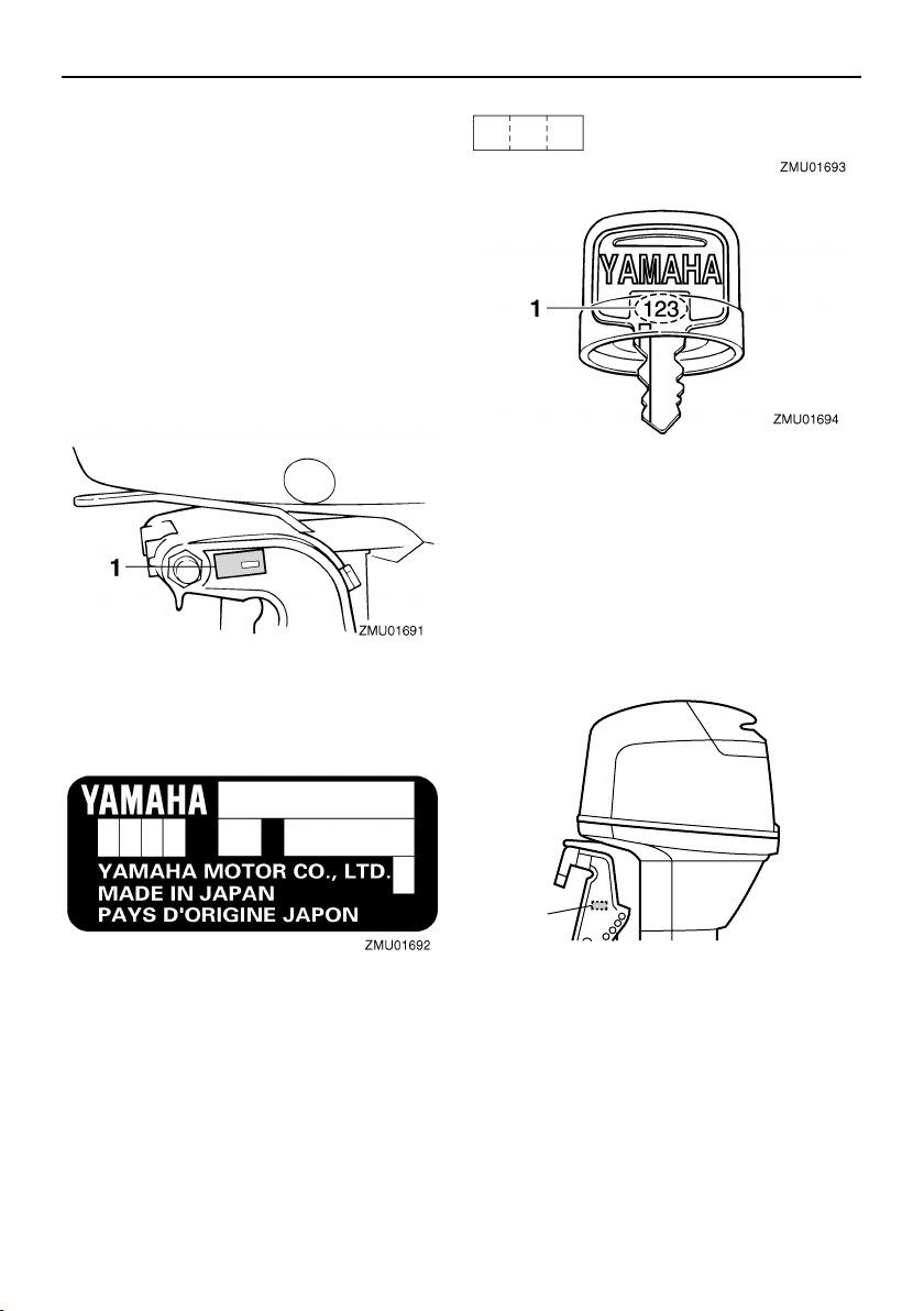
Outboard motor serial number
The outboard motor serial number is
stamped on the label attached to the port
side of the clamp bracket.
Record your outboard motor serial number in
the spaces provided to assist you in ordering
spare parts from your Yamaha dealer or for
reference in case your outboard motor is stolen.
1. Outboard motor serial number location
1. Key number
EMU25202
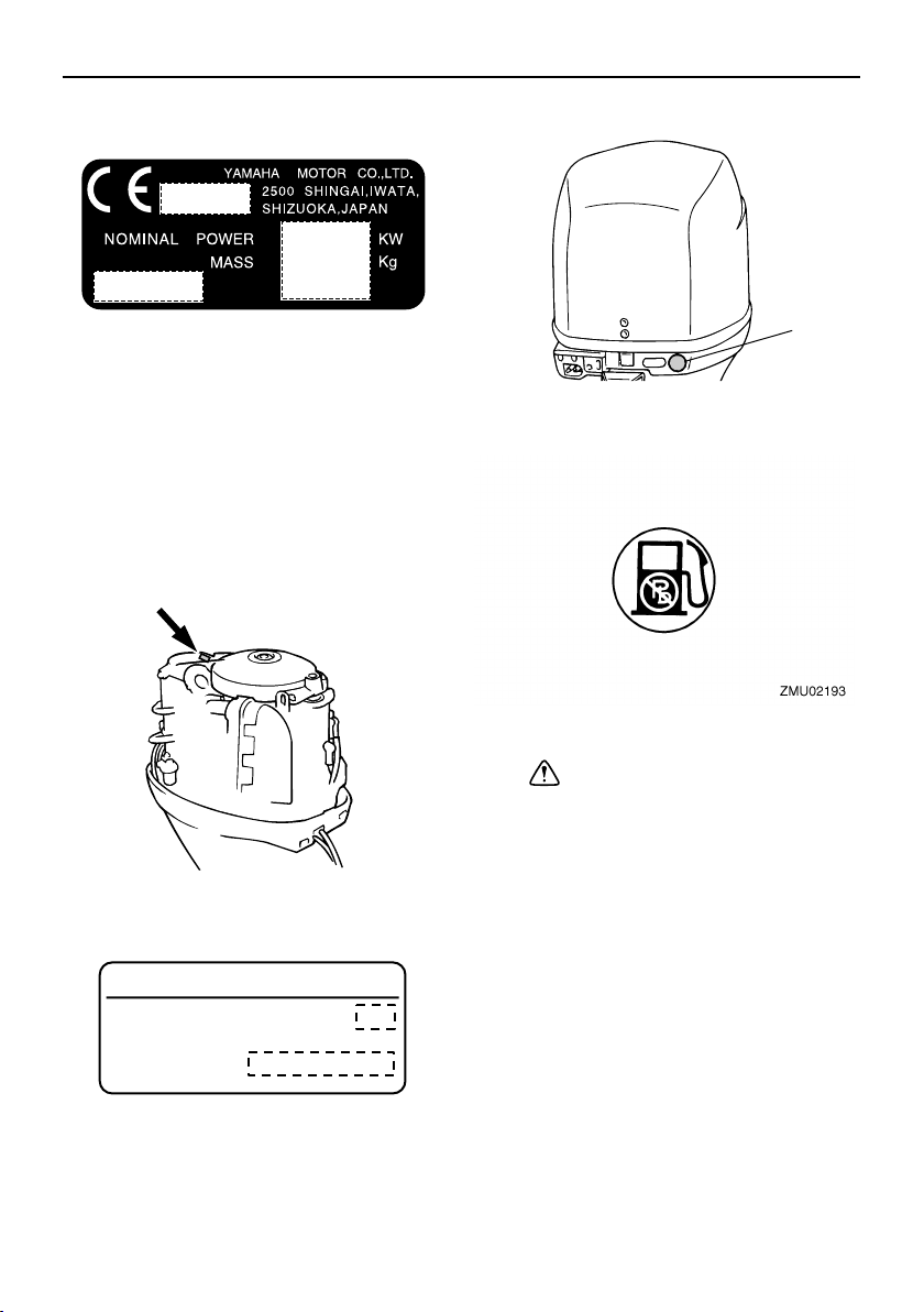
EC label
Engines affixed with this label conform to
certain portions of the European Parliament
directive relating to machinery. Refer to the
label and the EC Declaration of Conformity
for more details.
EMU25190
Key number
If a main key switch is equipped with the motor, the key identification number is stamped
on your key as shown in the illustration.
Record this number in the space provided for
reference in case you need a new key.
1
1
1. EC label location
ZMU04704
General information
Fuel requirement label
ZMU01696
EMU25221
Emission control information
EMU25351
SAV models
Engines affixed with the label pictured below
conform to SAV (the Swiss exhaust emission
regulations for Swiss inshore waters).
Approval label of emission control certificate
ZMU05466
YAMAHA MOTOR CO.,LTD.
Motorfamilie
AbgastypenprufNummer
ZMU04492
1
ZMU04031
1. Fuel requirement label location
EMU25371
Safety information
Before mounting or operating the outboard
●
motor, read this entire manual. Reading it
should give you an understanding of the
motor and its operation.
Before operating the boat, read any own-
●
er’s or operator’s manuals supplied with it
and all labels. Be sure you understand
each item before operating.
●
Do not overpower the boat with this outboard motor. Overpowering the boat could
result in loss of control. The rated power of
the outboard should be equal to or less
than the rated horsepower capacity of the
boat. If the rated horsepower capacity of
the boat is unknown, consult the dealer or
2

General information
boat manufacturer.
●
Do not modify the outboard. Modifications
could make the motor unfit or unsafe to
use.
●
Incorrect propeller selection and incorrect
use may not only cause engine damage,
but also adversely affect fuel consumption.
Consult your dealer for correct use.
Never operate after drinking alcohol or tak-
●
ing drugs. About 50% of all boating fatalities involve intoxication.
Have an approved personal flotation de-
●
vice (PFD) on board for every occupant. It
is a good idea to wear a PFD whenever
boating. At a minimum, children and nonswimmers should always wear PFDs, and
everyone should wear PFDs when there
are potentially hazardous boating conditions.
●
Gasoline is highly flammable, and its vapors are flammable and explosive. Handle
and store gasoline carefully. Make sure
there are no gas fumes or leaking fuel before starting the engine.
●
This product emits exhaust gases which
contain carbon monoxide, a colorless,
odorless gas which may cause brain damage or death when inhaled. Symptoms include nausea, dizziness, and drowsiness.
Keep cockpit and cabin areas well ventilated. Avoid blocking exhaust outlets.
●
Check throttle, shift, and steering for proper operation before starting the engine.
●
Attach the engine stop switch lanyard to a
secure place on your clothing, or your arm
or leg while operating. If you accidentally
leave the helm, the lanyard will pull from
the switch, stopping the engine.
Know the marine laws and regulations
●
where you will be boating - and obey them.
●
Stay informed about the weather. Check
weather forecasts before boating. Avoid
boating in hazardous weather.
Tell someone where you are going: leave
●
a Float Plan with a responsible person. Be
sure to cancel the Float Plan when you return.
●
Use common sense and good judgment
when boating. Know your abilities, and be
sure you understand how your boat handles under the different boating conditions
you may encounter. Operate within your
limits, and the limits of your boat. Always
operate at safe speeds, and keep a careful
watch for obstacles and other traffic.
Always watch carefully for swimmers dur-
●
ing the engine operation.
●
Stay away from swimming areas.
When a swimmer is in the water near you
●
shift into neutral and shut off the engine.
●
Do not illegally discard empty containers
used to replace or replenish oil. For the
correct processing of empty containers,
consult the dealer where you purchased
the oil.
●
When replacing oils used to lubricate the
product (engine or gear oil), be sure to
wipe away any spilt oil. Never pour oil without using a funnel or similar device. If necessary, verify the necessary replacement
procedure with the dealer.
●
Never illegally discard (dump) the product.
Yamaha recommends consulting the dealer on discarding the product.
3
General information
EMU25382
Important labels
EMU25395
Warning labels
ZMU04703
EMU25401
Label
EWM01260
WARNING
●
Be sure shift control is in neutral before
starting engine. (except 2HP)
●
Do not touch or remove electrical parts
when starting or during operation.
●
Keep hands, hair, and clothes away
from flywheel and other rotating parts
while engine is running.
EMU25465
Caution labels
ZMU04702
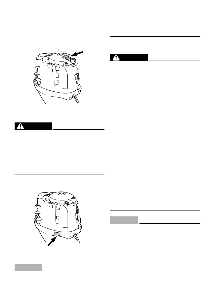
EMU25473
Label
ECM01191
CAUTION:
Transport and store the engine only as
shown. Otherwise, engine damage could
result from leaking oil.
EMU25540
Fueling instructions
EWM00010
WARNING
GASOLINE AND ITS VAPORS ARE HIGHLY FLAMMABLE AND EXPLOSIVE!
●
Do not smoke when refueling, and keep
away from sparks, flames, or other
sources of ignition.
●
Stop engine before refueling.
●
Refuel in a well-ventilated area. Refuel
portable fuel tanks off the boat.
●
Take care not to spill gasoline. If gasoline spills, wipe it up immediately with
dry rags.
●
Do not overfill the fuel tank.
●
Tighten the filler cap securely after refueling.
●
If you should swallow some gasoline,
inhale a lot of gasoline vapor, or get
gasoline in your eyes, get immediate
medical attention.
●
If any gasoline spills onto your skin, immediately wash with soap and water.
Change clothing if gasoline spills on it.
●
Touch the fuel nozzle to the filler opening or funnel to help prevent electrostatic sparks.
ECM00010
CAUTION:
Use only new clean gasoline which has
been stored in clean containers and is not
contaminated with water or foreign matter.
4
General information
EMU25580
Gasoline
Recommended gasoline:
Regular unleaded gasoline with a minimum octane rating of 90 (Research
Octane Number).
If knocking or pinging occurs, use a different
brand of gasoline or premium unleaded fuel.
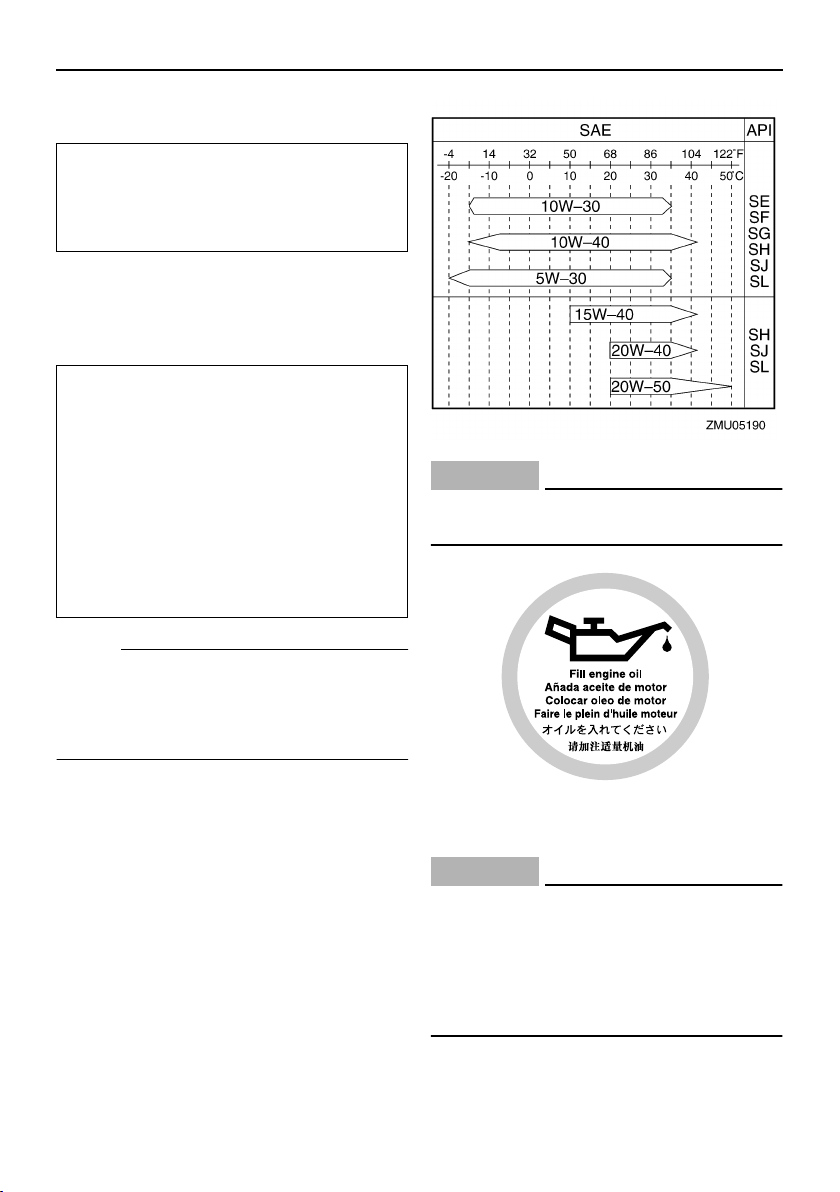
EMU25683
Engine oil
Recommended engine oil:
4-stroke motor oil with a combination
of the following SAE and API oil classifications
Engine oil type SAE:
10W-30 or 10W-40
Engine oil grade API:
SE, SF, SG, SH, SJ, SL
Engine oil quantity (excluding oil filter):
2.5 L (2.64 US qt) (2.20 Imp.qt)
ECM01050
CAUTION:
All 4-stroke engines are shipped from the
factory without engine oil.
NOTE:
If the recommended engine oil grades are
not available, select an alternative from the
following chart according to the average
temperatures in your area.
5
ZMU01710
EMU25700
Battery requirement
ECM01060
CAUTION:
Do not use a battery that does not meet
the specified capacity. If a battery which
does not meet specifications is used, the
electric system could perform poorly or
be overloaded, causing electric system
damage.
For electric start models, choose a battery
which meets the following specifications.
EMU25720
Battery specifications
General information
Minimum cold cranking amps (CCA/EN):
430.0 A
Minimum rated capacity (20HR/IEC):
70.0 Ah
NOTE:
The engine cannot be started if battery voltage is too low.
EMU25742
Propeller selection
The performance of your outboard motor will
be critically affected by your choice of propeller, as an incorrect choice could adversely
affect performance and could also seriously
damage the motor. Engine speed depends
on the propeller size and boat load. If engine
speed is too high or too low for good engine
performance, this will have an adverse effect
on the engine.
Yamaha outboard motors are fitted with propellers chosen to perform well over a range
of applications, but there may be uses where
a propeller with a different pitch would be
more appropriate. For a greater operating
load, a smaller-pitch propeller is more suitable as it enables the correct engine speed
to be maintained. Conversely, a larger-pitch
propeller is more suitable for a smaller operating load.
Yamaha dealers stock a range of propellers,
and can advise you and install a propeller on
your outboard that is best suited to your application.
x
-
123
ZMU04606
1. Propeller diameter in inches
2. Propeller pitch in inches
3. Type of propeller (propeller mark)
x
-
123
ZMU04607
1. Propeller diameter in inches
2. Propeller pitch in inches
3. Type of propeller (propeller mark)
NOTE:
Select a propeller which will allow the engine
to reach the middle or upper half of the operating range at full throttle with the maximum
boat load. If operating conditions such as
light boat loads then allow the engine r/min to
rise above the maximum recommended
range, reduce the throttle setting to maintain
the engine in the proper operating range.
For instructions on propeller removal and installation, see page 67.
6
General information
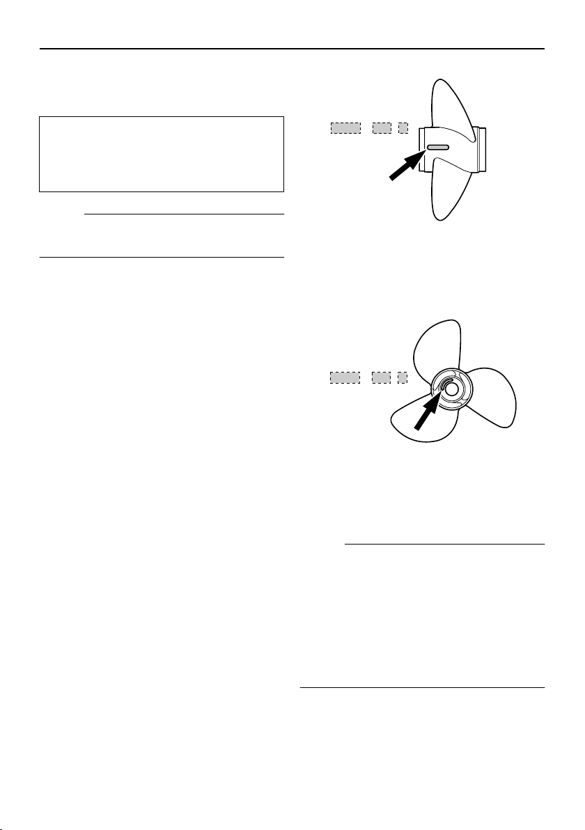
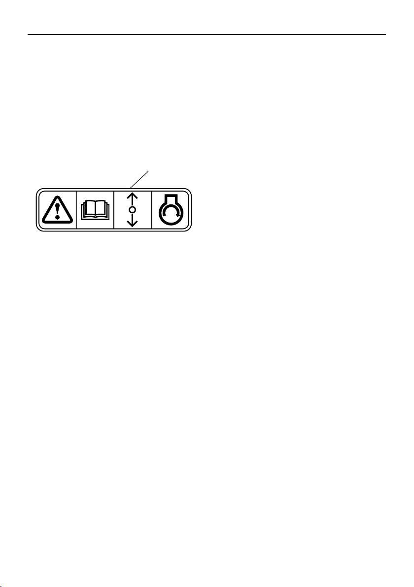
EMU25760
Start-in-gear protection
Yamaha outboard motors affixed with the
pictured label or Yamaha-approved remote
control units are equipped with start-in-gear
protection device(s). This feature permits the
engine to be started only when it is in neutral.
Always select neutral before starting the engine.
1
ZMU01713
1. Start-in-gear protection label
7
Basic components
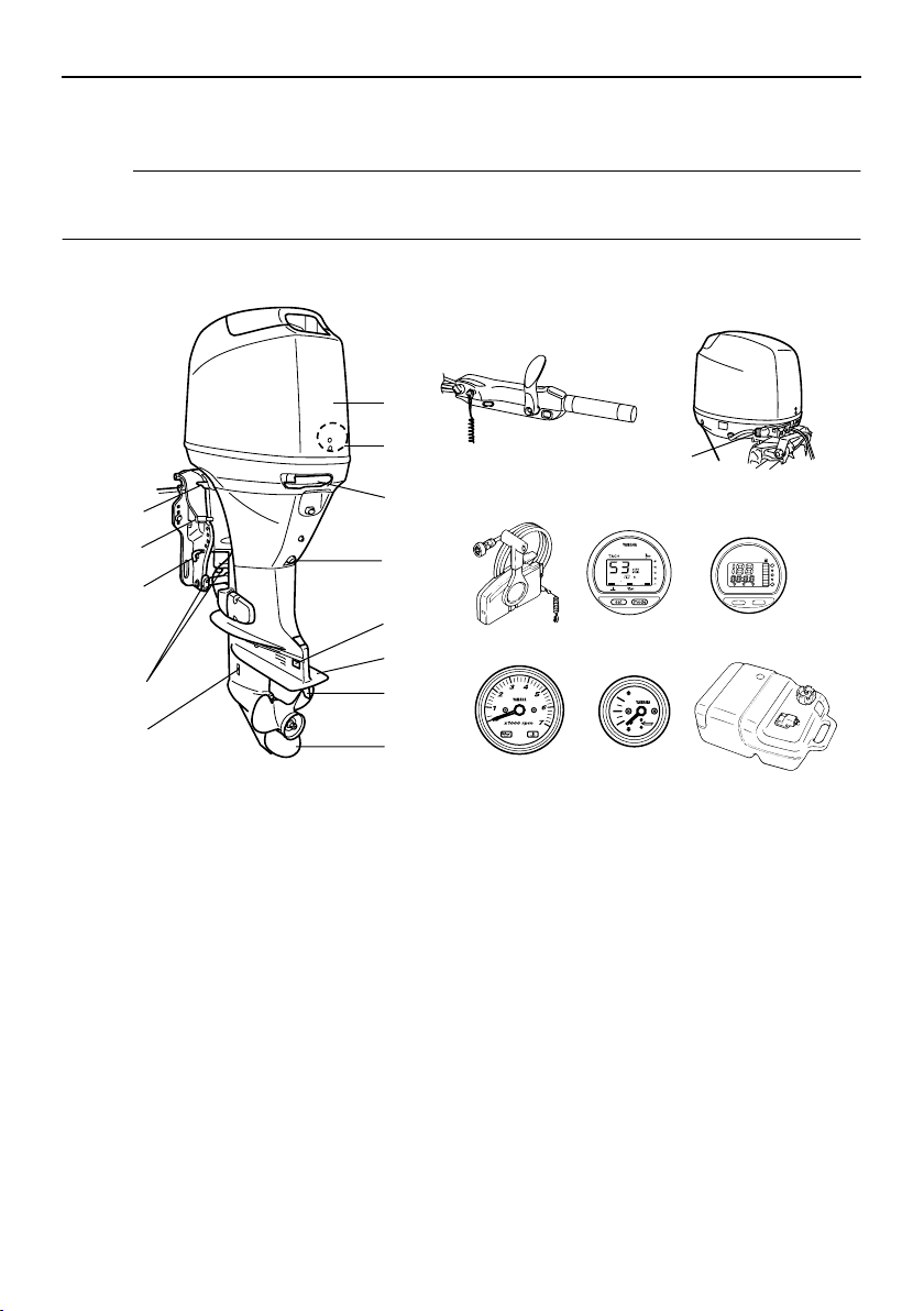
EMU25799
Main components
NOTE:
* May not be exactly as shown; also may not be included as standard equipment on all models.
F40D, F50F, FT50G, F60C, FT60D
14
1
13
12
11
10
9
1. Top cowling
2. Water separator
3. Top cowling lock lever
4. Drain screw
5. Anode
6. Anti-cavitation plate
7. Trim tab (anode)
8. Propeller
9. Cooling water inlet
10. Anode(s)
11. Tilt rod*
12. Tilt lock lever*
13. Tilt support lever
14. Tiller handle*
2
15
3
16
4
17 18
SPEED
TRIP TIME BATT
set
YAMAHA
Km/h
knot
mph
km
mile
mode
5
19
6
20 21
7
8
ZMU05106
15. Flushing device*
16. Remote control box (side mount type)*
17. Digital tachometer*
18. Digital speedometer*
19. Tachometer*
20. Trim meter*
21. Fuel tank
8
Basic components
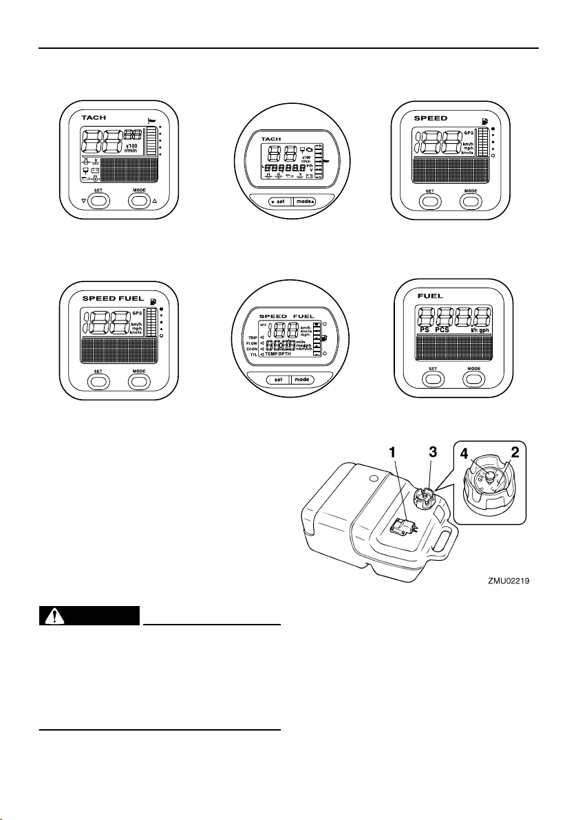
1
4
1. Tachometer unit (Square type)*
2. Tachometer unit (Round type)*
3. Speedometer unit (Square type)*
4. Speed & fuel meter unit (Square type)*
5. Speed & fuel meter unit (Round type)*
6. Fuel management meter (Square type)*
2
5
3
6
ZMU05429
EMU25802
Fuel tank
If your model was equipped with a portable
fuel tank, its function is as follows.
EWM00020
WARNING
The fuel tank supplied with this engine is
its dedicated fuel reservoir and must not
be used as a fuel storage container. Commercial users should conform to relevant
licensing or approval authority regulations.
9
1. Fuel joint
2. Fuel gauge
3. Fuel tank cap
4. Air vent screw
EMU25830
Fuel joint
This joint is used to connect the fuel line.
Basic components
EMU25841
Fuel gauge
This gauge is located on either the fuel tank
cap or on the fuel joint base. It shows the approximate amount of fuel remaining in the
tank.
EMU25850
Fuel tank cap
This cap seals the fuel tank. When removed,
the tank can be filled with fuel. To remove the
cap, turn it counterclockwise.
EMU25860
Air vent screw
This screw is on the fuel tank cap. To loosen
the screw, turn it counterclockwise.
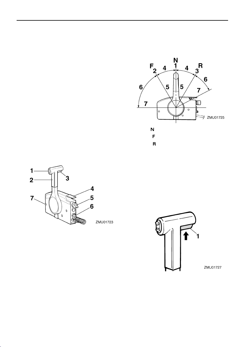
EMU26180
Remote control
The remote control lever actuates both the
shifter and the throttle. The electrical switches are mounted on the remote control box.
engine will continue to run at idle until the lever is moved about 35° (a detent can be felt).
Moving the lever farther opens the throttle,
and the engine will begin to accelerate.
1. Neutral “”
2. Forward “”
3. Reverse “”
4. Shift
5. Fully closed
6. Throttle
7. Fully open
EMU26201
Neutral interlock trigger
To shift out of neutral, first pull the neutral interlock trigger up.
1. Power trim and tilt switch
2. Remote control lever
3. Neutral interlock trigger
4. Neutral throttle lever
5. Main switch / choke switch
6. Engine stop lanyard switch
7. Throttle friction adjuster
EMU26190
Remote control lever
Moving the lever forward from the neutral position engages forward gear. Pulling the lever back from neutral engages reverse. The
1. Neutral interlock trigger
EMU26211
Neutral throttle lever
To open the throttle without shifting into either forward or reverse, put the remote con-
10
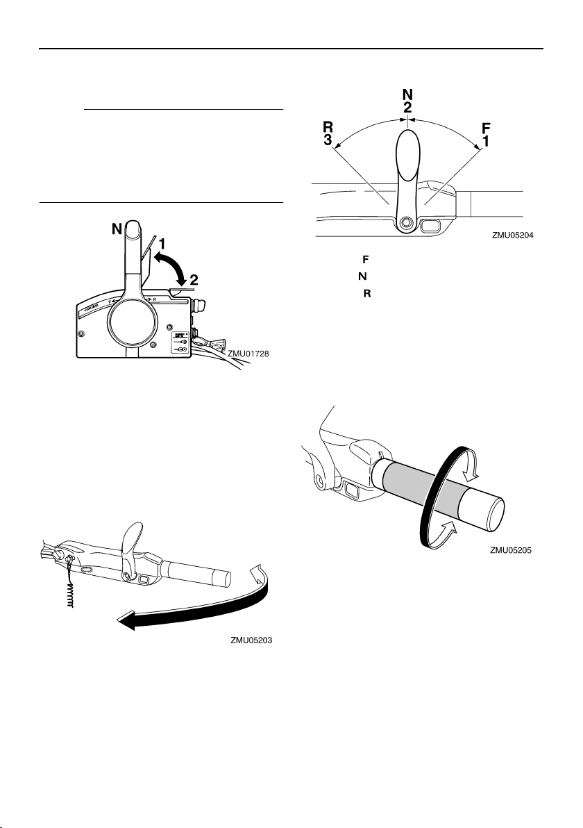
Basic components
trol lever in the neutral position and lift the
neutral throttle lever.
NOTE:
The neutral throttle lever will operate only
when the remote control lever is in neutral.
The remote control lever will operate only
when the neutral throttle lever is in the closed
position.
1. Fully open
2. Fully closed
EMU25911
Tiller handle
To change direction, move the tiller handle to
the left or right as necessary.
the boat moves astern.
1. Forward “”
2. Neutral “”
3. Reverse “”
EMU25941
Throttle grip
The throttle grip is on the tiller handle. Turn
the grip counterclockwise to increase speed
and clockwise to decrease speed.
EMU25922
Gear shift lever
Pulling the gear shift lever towards you puts
the engine in forward gear so that the boat
moves ahead. Pushing the lever away from
you puts the engine in reverse gear so that
11
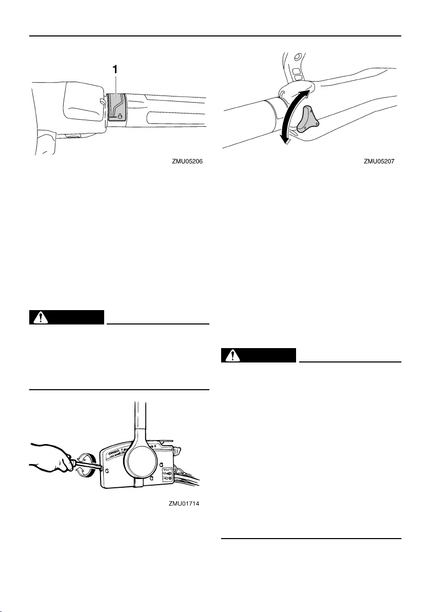
EMU25961
Throttle indicator
The fuel consumption curve on the throttle
indicator shows the relative amount of fuel
consumed for each throttle position. Choose
the setting that offers the best performance
and fuel economy for the desired operation.
Basic components
1. Throttle indicator
EMU25971
Throttle friction adjuster
A friction device provides adjustable resistance to movement of the throttle grip or the
remote control lever, and can be set according to operator preference.
To increase resistance, turn the adjuster
clockwise. To decrease resistance, turn the
adjuster counterclockwise.
EWM00031
WARNING
Do not overtighten the friction adjuster. If
there is too much resistance, it could be
difficult to move the remote control lever
or throttle grip, which could result in an
accident.
When constant speed is desired, tighten the
adjuster to maintain the desired throttle setting.
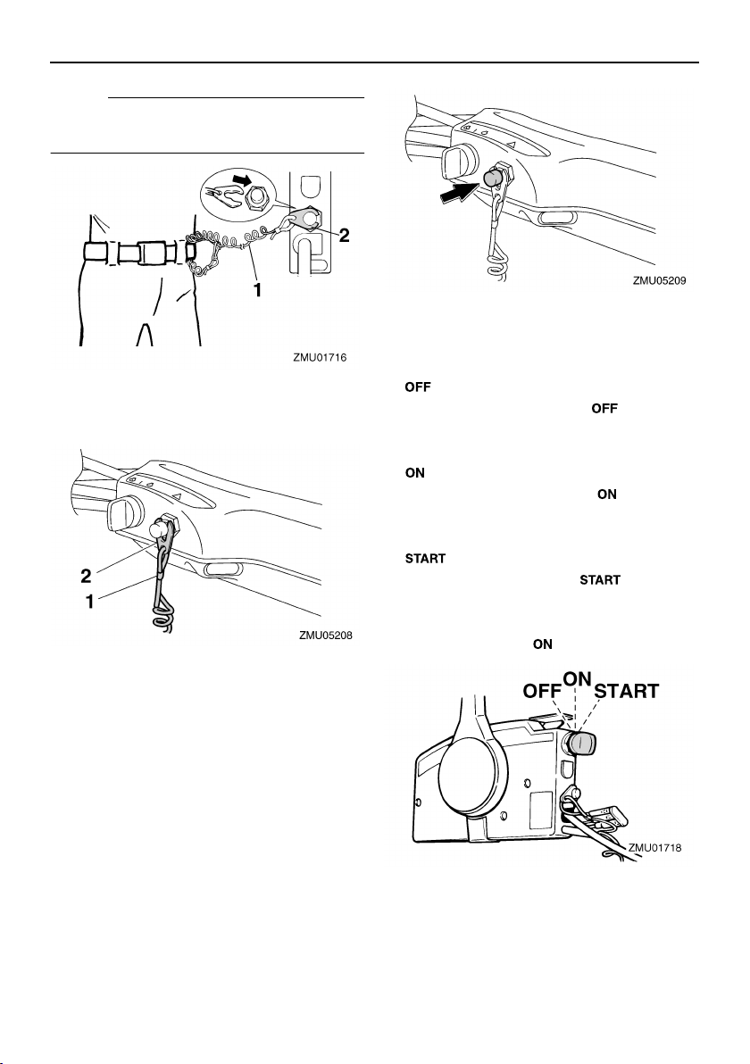
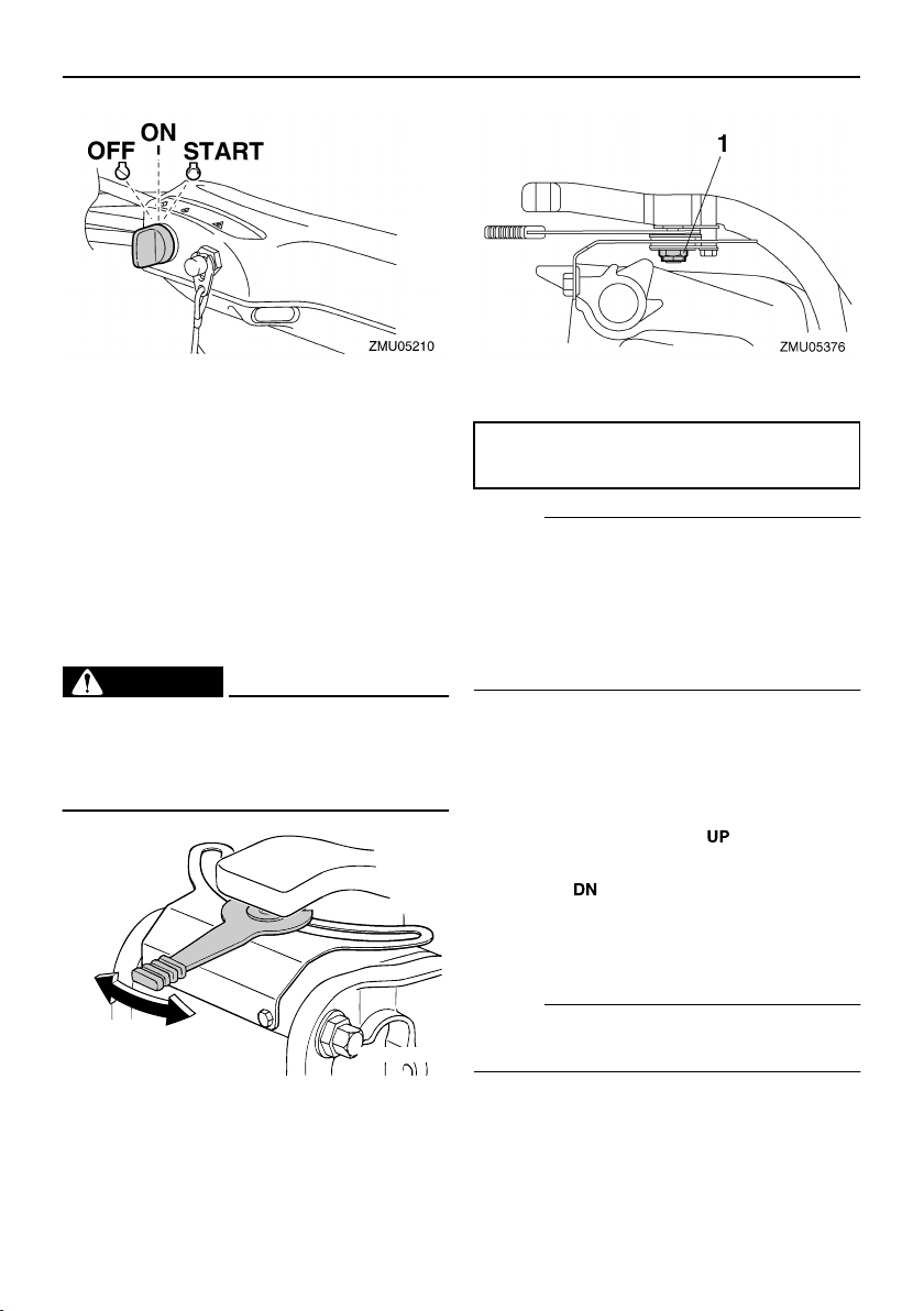
EMU25990
Engine stop lanyard switch
The lock plate must be attached to the engine stop switch for the engine to run. The
lanyard should be attached to a secure place
on the operator’s clothing, or arm or leg.
Should the operator fall overboard or leave
the helm, the lanyard will pull out the lock
plate, stopping ignition to the engine. This
will prevent the boat from running away under power.
EWM00120
WARNING
Attach the engine stop switch lanyard
●
to a secure place on your clothing, or
your arm or leg while operating.
Do not attach the lanyard to clothing
●
that could tear loose. Do not route the
lanyard where it could become entangled, preventing it from functioning.
Avoid accidentally pulling the lanyard
●
during normal operation. Loss of engine power means the loss of most
steering control. Also, without engine
power, the boat could slow rapidly. This
could cause people and objects in the
boat to be thrown forward.
12
Basic components
NOTE:
The engine cannot be started with the lock
plate removed.
1. Lanyard
2. Lock plate
1. Lanyard
2. Lock plate
EMU26090
Main switch
The main switch controls the ignition system;
its operation is described below.
“”
●
With the main switch in the “” (off) posi-
tion, the electrical circuits are off, and the key
can be removed.
●
With the main switch in the “” (on) posi-
tion, the electrical circuits are on, and the key
cannot be removed.
●
With the main switch in the “” (start) po-
sition, the starter motor turns to start the engine. When the key is released, it returns
automatically to the “” (on) position.
(off)
“”
(on)
“”
(start)
EMU26001
Engine stop button
To open the ignition circuit and stop the engine, push this button.
13
Basic components
EMU31430
Steering friction adjuster
A friction device provides adjustable resistance to the steering mechanism, and can be
set according to operator preference. An adjuster lever is located on the bottom of the
tiller handle bracket.
To increase resistance, turn the lever to the
port side “A”.
To decrease resistance, turn the lever to the
starboard side “B”.
EWM00040
WARNING
Do not overtighten the friction adjuster. If
there is too much resistance, it could be
difficult to steer, which could result in an
accident.
B
A
ZMU02810
1. Nut
Nut tightening torque:
3.7 Nm (2.7 ft-lb) (0.4 kgf-m)
NOTE:
●
Check the tiller handle for smooth movement when the lever is turned to the starboard side “B”.
●
Do not apply lubricants such as grease to
the friction areas of the steering friction adjuster.
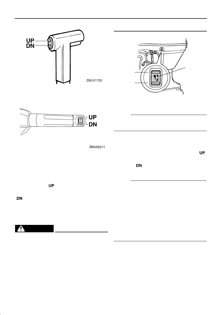
EMU26141
Power trim and tilt switch on remote
control or tiller handle
The power trim and tilt system adjusts the
outboard motor angle in relation to the transom. Pressing the switch “” (up) trims the
outboard motor up, then tilts it up. Pressing
the switch “” (down) tilts the outboard mo-
tor down and trims it down. When the switch
is released, the outboard motor will stop in its
current position.
NOTE:
For instructions on using the power trim and
tilt switch, see pages 42 and 45.
If the resistance does not increase even
when the lever is turned to the port side “A”,
make sure that the nut is tightened to the
specified torque.
14
Basic components
EMU26151
Power trim and tilt switch on bottom
engine cowling
The power trim and tilt switch is located on
the side of the bottom engine cowling. Pressing the switch “” (up) trims the outboard
motor up, then tilts it up. Pressing the switch
“” (down) tilts the outboard motor down
and trims it down. When the switch is released, the outboard motor will stop in its
current position.
EWM01030
WARNING
Use the power trim and tilt switch located
on the bottom engine cowling only when
the boat is at a complete stop with the engine off. Attempting to use this switch
while the boat is moving could increase
the risk of falling overboard and could
distract the operator, increasing the risk
of collision with another boat or an obsta-
cle.
1
UP
DN
ZMU03634
1. Power trim and tilt switch
NOTE:
For instructions on using the power trim and
tilt switch, see page 45.
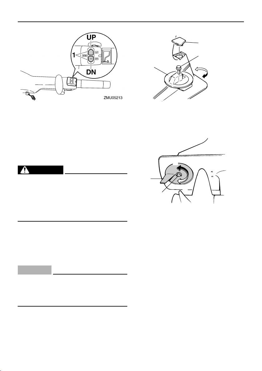
EMU30900
Variable trolling RPM switches
The trolling speed can be adjusted when the
outboard motor is trolling. Press the “”
switch to increase the trolling speed and
press the “” switch to decrease the trolling
speed.
NOTE:
●
The trolling speed changes approximately
50 r/min each time a switch is pressed.
●
If the trolling speed has been adjusted, the
engine returns to the normal trolling speed
when the engine is stopped and restarted
or when the engine speed exceeds approximately 3000 r/min.
For instructions on using the variable troll-
●
ing RPM switches, see page 41.
15
Basic components
3
2
1
B
A
ZMU02525
1. Variable trolling RPM switch
EMU26241
Trim tab with anode
The trim tab should be adjusted so that the
steering control can be turned to either the
right or left by applying the same amount of
force.
EWM00840
WARNING
An improperly adjusted trim tab could
cause difficult steering. Always test run
after the trim tab has been installed or replaced to be sure steering is correct. Be
sure you have tightened the bolt after adjusting the trim tab.
If the boat tends to veer the left (port side),
turn the trim tab rear end to the port side “A”
in the figure. If the boat tends to veer the right
(starboard side), turn the trim tab end to the
starboard side “B” in the figure.
ECM00840
CAUTION:
The trim tab also serves as an anode to
protect the engine from electrochemical
corrosion. Never paint the trim tab as it
will become ineffective as an anode.
1. Trim tab
2. Bolt
3. Cap
A
1
2
1. Trim tab
2. Bolt
EMU26261
Trim rod (tilt pin)
The position of the trim rod determines the
minimum trim angle of the outboard motor in
relation to the transom.
B
ZMU03097
16
Basic components
ZMU03593
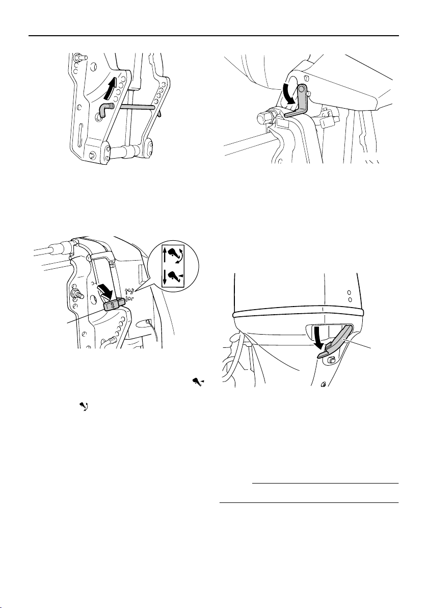
EMU26312
Tilt lock mechanism
The tilt lock mechanism is used to prevent
the outboard motor from lifting out of the water when in reverse gear.
1
ZMU03594
1. Tilt lock lever
To lock it, set the tilt lock lever in the “”
(lock) position. To release, push the tilt lock
lever in the “” (release) position.
EMU26340
Tilt support lever for power trim and
tilt or hydro tilt model
To keep the outboard motor in the tilted up
position, lock the tilt support lever to the
clamp bracket.
ZMU03595
EMU26372
Top cowling lock lever(s) (turn type)
To remove the engine top cowling, turn the
lock lever(s) and lift off the cowling. When installing the cowling, check to be sure it fits
properly in the rubber seal. Then lock the
cowling again by returning the lever(s) to the
lock position.
1
ZMU05093
1. Top cowling lock lever(s)
EMU26460
Flushing device
This device is used to clean the cooling water passages of the motor using a garden
hose and tap water.
NOTE:
For details on usage, see page 58.
17
1. Flushing device
Basic components
details on how to read the warning indicator,
see page 29.
1
ZMU05095
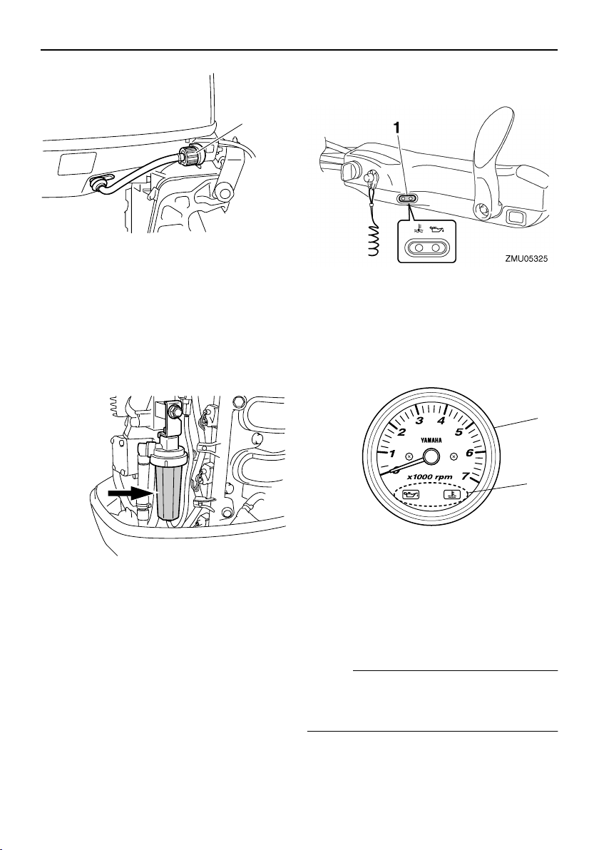
EMU31702
Water separator
This engine has a combination fuel filter/water separator and associated warning system. If water separated from the fuel
exceeds a specific volume, the warning device will activate.
ZMU05474
Activation of warning device
●
The water separator warning indicator will
blink.
The buzzer will sound intermittently only
●
when the gear shift is in neutral.
If the warning system has activated, stop
●
the engine and consult a Yamaha dealer
immediately.
EMU26301
Warning indicator
If the engine develops a condition which is
cause for warning, the indicator lights up. For
1. Warning indicator
EMU26470
Tachometer
This gauge shows the engine speed and has
the following functions.
1
2
ZMU04578
1. Tachometer
2. Warning indicator(s)
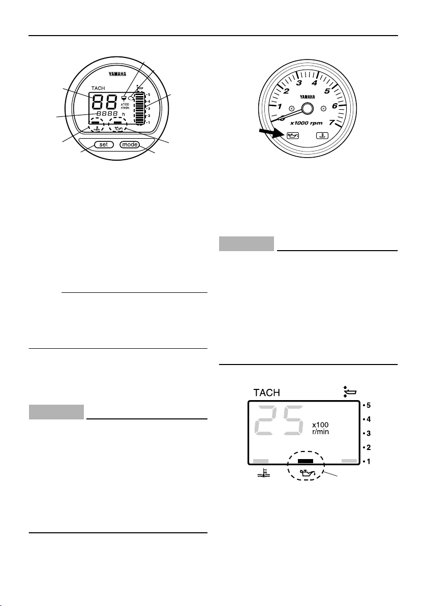
EMU26491
Digital tachometer
The tachometer shows the engine speed
and has the following functions.
NOTE:
All segments of the display will light momentarily after the main switch is turned on and
will return to normal thereafter.
18
Basic components
6
7
1
2
3
5
8
1. Tachometer
2. Trim meter
3. Hour meter
4. Low oil pressure warning indicator
5. Overheat warning indicator
6. Water separator warning indicator
7. Engine trouble warning indicator
8. Set button
9. Mode button
NOTE:
The water separator and engine trouble
warning indicators only operate when the engine is equipped with the appropriate functions.
EMU26503
Low oil pressure warning indicator
If oil pressure drops too low, this indicator will
flash. For further information, see page 29.
ECM00020
CAUTION:
●
Do not continue to run the engine if the
low oil pressure warning indicator is on
and the engine oil level is lower. Serious engine damage will occur.
●
The low oil pressure warning indicator
does not indicate the engine oil level.
Use the oil dipstick to check the remaining oil quantity. For further information, see page 34.
9
4
ZMU04185
ZMU04754
EMU26522
Low oil pressure warning indicator
If oil pressure drops too low, the warning indicator will start to blink. For further information, see page 29.
ECM00020
CAUTION:
●
Do not continue to run the engine if the
low oil pressure warning indicator is on
and the engine oil level is lower. Serious engine damage will occur.
●
The low oil pressure warning indicator
does not indicate the engine oil level.
Use the oil dipstick to check the remaining oil quantity. For further information, see page 34.
1
ZMU01736
1. Low oil pressure warning indicator
EMU26572
Overheat warning indicator
If the engine temperature rises too high, this
19
Basic components
indicator will flash. For further information on
reading the indicator, see page 29.
ECM00050
CAUTION:
Do not continue to run the engine if the
overheat warning indicator is on. Serious
engine damage will occur.
ZMU04715
EMU26581
Overheat warning indicator (digital
type)
If the engine temperature rises too high, the
warning indicator will start to blink. For further information on reading the indicator, see
page 29.
ECM00050
CAUTION:
Do not continue to run the engine if the
overheat warning indicator is on. Serious
engine damage will occur.
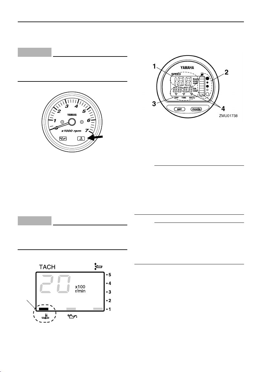
EMU26600
Speedometer (digital type)
This gauge shows the boat speed.
1. Speedometer
2. Fuel gauge
3. Trip meter/clock/voltmeter
4. Warning indicator(s)
NOTE:
After the main switch is first turned on, all
segments of the display come on as a test.
After a few seconds, the gauge will change
to normal operation. Watch the gauge when
turning on the main switch to make sure all
segments come on.
NOTE:
The speedometer displays km/h, mph, or
knots, according to operator preference. Select the desired unit of measurement by setting the selector switch on the back of the
gauge. See the illustration for settings.
1
1. Overheat warning indicator
ZMU01737
20
 Loading...