

Page 1

F50A
FT50B
FT50C
SERVICE MANUAL
290408
62Y-28197-3A-11
Page 2

NOTICE
This manual has been prepared by Yamaha primarily for use by Yamaha dealers and their trained
mechanics when performing maintenance procedures and repairs to Yamaha equipment. It has
been written to suit the needs of persons who have a basic understanding of the mechanical and
electrical concepts and procedures inherent in the work, for without such knowledge attempted
repairs or service to the equipment could render it unsafe or unfit for use.
Because Yamaha has a policy of continuously improving its products, models may differ in detail
from the descriptions and illustrations given in this publication. Use only the latest edition of this
manual. Authorized Yamaha dealers are notified periodically of modifications and significant
changes in specifications and procedures, and these are incorporated in successive editions of this
manual.
Important information
Particularly important information is distinguished in this manual by the following notations:
The Safety Alert Symbol means ATTENTION! BECOME ALERT! YOUR SAFETY IS
INVOLVED!
WARNING
Failure to follow WARNING instructions could result in severe injury or death to the machine
operator, a bystander, or a person inspecting or repairing the outboard motor.
CAUTION:
A CAUTION indicates special precautions that must be taken to avoid damage to the outboard motor.
NOTE:
A NOTE provides key information to make procedures easier or clearer.
1
F50A, FT50B, FT50C
SERVICE MANUAL
©2000 by Yamaha Motor Co., Ltd.
1st Edition, November 2000
All rights reserved.
Any reprinting or unauthorized use
without the written permission of
Yamaha Motor Co., Ltd.
is expressly prohibited.
Printed in the Netherlands
Page 3

Contents
General information
Specifications
Periodic checks and adjustments
Fuel system
GEN
INFO
SPEC
CHK
ADJ
FUEL
1
2
3
4
Power unit
Lower unit
Bracket unit
Electrical systems
POWR
LOWR
BRKT
–+
ELEC
5
6
7
8
Index
Page 4

Page 5

GEN
INFO
General information
How to use this manual.................................................................................1-1
Manual format............................................................................................1-1
Symbols.....................................................................................................1-2
Safety while working......................................................................................1-3
Fire prevention...........................................................................................1-3
Ventilation..................................................................................................1-3
Self-protection ...........................................................................................1-3
Parts, lubricants, and sealants ..................................................................1-3
Good working practices .............................................................................1-4
Disassembly and assembly .......................................................................1-4
Identification...................................................................................................1-5
Applicable models .....................................................................................1-5
Serial number ............................................................................................1-5
Features and benefits....................................................................................1-6
Newly designed four carburetors............................................................... 1-6
CDI unit with microcomputer .....................................................................1-7
Lower unit ..................................................................................................1-8
Technical tips ...............................................................................................1-10
Carburetor ...............................................................................................1-10
Acceleration pump...................................................................................1-15
Ignition system.........................................................................................1-17
Ignition timing control...............................................................................1-19
Power trim and tilt....................................................................................1-22
1
2
3
4
5
62Y3A11
Propeller selection.......................................................................................1-32
Propeller size...........................................................................................1-32
Selection..................................................................................................1-32
Predelivery checks ......................................................................................1-33
Checking the fuel system ........................................................................1-33
Checking the gear oil...............................................................................1-33
Checking the engine oil ...........................................................................1-33
Checking the battery................................................................................1-33
Checking the outboard motor mounting position.....................................1-34
Checking the remote control cables ........................................................1-34
Checking the steering wheel/tiller handle................................................1-34
Checking the gearshift and throttle operation..........................................1-34
Checking the tilt system...........................................................................1-35
Checking the engine start switch and
engine stop switch/engine shut-off switch .............................................1-35
Checking the pilot water outlet ................................................................1-35
Test run ...................................................................................................1-35
Break-in ...................................................................................................1-36
After test run ............................................................................................1-36
6
7
8
I
Page 6

GEN
INFO
General information
How to use this manual
Manual format
The format of this manual has been designed to make service procedures clear and easy to understand. Use the information below as a guide for effective and quality service.
1
Parts are shown and detailed in an exploded diagram and are listed in the components list.
2
Tightening torque specifications are provided in the components list at the beginning of each
section and after a numbered step with tightening instructions.
3
Symbols are used to indicate important aspects of a procedure, such as the grade of lubricant
and lubrication point.
4
The components list consist of parts and part quantities, as well as bolt and screw dimensions.
5
Service points regarding removal, checking, and installation are shown in individual illustrations
to explain the relevant procedure.
6
This service manual has two types of special service tools. Use part numbers that start with “J-”,
“YB-”, “YM-”, “YS-”, “YU-”, “YW-”, or “YX-” for USA and Canada. Use parts numbers that start
with “90890-” for all other countries.
POWR
Cylinder head
Power unit
No. Part name Q’ty Remarks
1 Cylinder head 1
2Oil pump1
3 Cylinder head cover 1
4Bolt 7 M6 × 20 mm
5 Cylinder head cover
gasket
6 Bolt 10 M9 × 95 mm 1st
7 Spark plug 4 18 1.8 13
8Bolt 5 M6 × 25 mm 1st
9 Dowel pin 2
10 Cylinder head gasket 1
11 Grommet 4
12 Anode 4
13 Cover 4
14 Bolt 4
15 Cover 4
16 Bolt 4
17 O-ring 1
18 O-ring 1
19 O-ring 1
20 Bolt 4 M6 × 40 mm
21 Housing 1
22 Drive shaft 1
23 Pin 1
24 Inner rotor 1
25 Outer rotor 1
26 Gasket 1
27 Cover 1
28 Screw 2 M6 × 20 mm
È
Tightening sequence
POWR
Removing the timing belt and
sprockets
1. Set the cylinder #1 piston position to
1
Not reusable
Not reusable
Power unit
Not reusable
Not reusable
TDC of the compression stroke by aligning the “1” mark a on the driven sprocket
with the “” mark b on the cylinder
head.
Not reusable
Not reusable
Cylinder head
Tightening torques
Stage N·mkgf·mft·lb
2.3
2nd2347
4.71734
0.6
2nd612
3. Remove the tensioner 4 and timing belt
5
4.3
1.2
8.7
from the driven sprocket side.
5
1
1-1
5-35
62Y1A11
62Y1A11
CAUTION:
Do not turn the drive sprocket counterclockwise, otherwise the valve system
may be damaged.
2. Remove the breather hose and loosen
the drive sprocket nut 1.
NOTE:
• Use a deep socket 2 (M42) for this proce-
dure.
• Do not turn the camshaft when loosening
the drive sprocket nut.
Crankshaft holder 3: YB-06562
Crankshaft holder 18 3: 90890-06562
5-31
4. Loosen the driven sprocket bolt 6 and
remove the driven sprocket .
For USA and Canada
È
For worldwide
É
NOTE:
Do not turn the camshaft when loosening the
driven sprocket bolt.
Flywheel magnet holder: YB-06139
Flywheel holder: 90890-06522
5-36
62Y1A11
62Y3A11
Page 7

How to use this manual
Symbols
The symbols below are designed to indicate the content of a chapter.
General information
GEN
INFO
Specifications
SPEC
Periodic checks and adjustments
CHK
ADJ
Fuel system
FUEL
Symbols 1 to 5 in an exploded diagram indicate the grade of lubricant and the lubrication point.
12345
Power unit
POWR
Lower unit
LOWR
Bracket unit
BRKT
Electrical systems
ELEC
– +
1
2
3
4
A M
E
Apply Yamaha 4-stroke motor oil
1
Apply water resistant grease (Yamaha grease A, Yamaha marine grease)
2
Apply molybdenum disulfide grease
3
Apply anti-corrosion grease (Yamaha grease D)
4
Apply low temperature resistant grease (Yamaha grease C)
5
Symbols 6 to A in an exploded diagram indicate the type of sealant or locking agent and the application point.
67890A
GM
Apply Gasket Maker
6
Apply Yamabond No. 4
7
Apply LOCTITE
8
Apply LOCTITE
9
Apply LOCTITE
0
Apply silicon sealant
A
4
®
®
No. 271 (Red LOCTITE)
®
No. 242 (Blue LOCTITE)
®
No. 572
LT
271
LT
242
D C
LT
572
SS
5
6
7
8
62Y3A11
1-2
I
Page 8

GEN
INFO
General information
Safety while working
To prevent an accident or injury and to
ensure quality service, follow the safety procedures provided below.
Fire prevention
Gasoline is highly flammable.
Keep gasoline and all flammable products
away from heat, sparks, and open flames.
Ventilation
Gasoline vapor and exhaust gas are heavier
than air and extremely poisonous. If inhaled
in large quantities they may cause loss of
consciousness and death within a short time.
When test running an engine indoors (e.g., in
a water tank) be sure to do so where adequate ventilation can be maintained.
1
Parts, lubricants, and sealants
Use only genuine Yamaha
and sealants or those recommended by
Yamaha, when servicing or repairing the
outboard motor.
Under normal conditions, the lubricants mentioned in this manual should not harm or be
hazardous to your skin. However, you should
follow these precautions to minimize any risk
when working with lubricants.
parts, lubricants,
Self-protection
Protect your eyes by wearing safety glasses
or safety goggles during all operations involving drilling and grinding, or when using an air
compressor.
Protect your hands and feet by wearing protective gloves and safety shoes when necessary.
1-3
1. Maintain good standards of personal and
industrial hygiene.
2. Change and wash clothing as soon as
possible if soiled with lubricants.
3. Avoid contact with skin. Do not, for
example, place a soiled rag in your
pocket.
4. Wash hands and any other part of the
body thoroughly with soap and hot water
after contact with a lubricant or lubricant
soiled clothing has been made.
5. To protect your skin, apply a protective
cream to your hands before working on
the outboard motor.
62Y3A11
Page 9

6. Keep a supply of clean, lint-free cloths for
wiping up spills, etc.
Good working practices
Special tools
Use the recommended special tools to protect parts from damage. Use the right tool in
the right manner—do not improvise.
Tightening torques
Follow the tightening torque specifications
provided throughout the manual. When tightening nuts, bolts, and screws, tighten the
large sizes first, and tighten fasteners starting
in the center and moving outward.
Non-reusable parts
Always use new gaskets, seals, O-rings, cotter pins, circlips, etc., when installing or
assembling parts.
Safety while working
3. Install bearings with a manufacture identification mark in the direction indicated in
the installation procedure. In addition, be
sure to lubricate the bearings liberally.
4. Apply a thin coat of water-resistant
grease to the lip and out periphery of an
oil seal before installation.
5. Check that moving parts operate normally after assembly.
1
2
3
4
5
Disassembly and assembly
1. Use compressed air to remove dust and
dirt during disassembly.
2. Apply engine oil to the contact surfaces
of moving parts before assembly.
62Y3A11
1-4
6
7
8
I
Page 10

GEN
INFO
General information
Identification
Applicable models
This manual covers the following models.
Applicable models
USA, Canada Worldwide
— F50AEHD
F50TH F50AEHT
— F50AED
F50TR F50AET
T50TR FT50BET
— FT50CEHD
— FT50CED
— FT50CET
Serial number
The outboard motor serial number is
stamped on a label attached to the port
clamp bracket.
1
Model name
Approved
model code
Starting
serial No.
USA, Canada
F50TH
L: 451812–
62Y
F50TR L: 421732–
T50TR 64J L: 406850–
Worldwide
F50AEHD
L: 350505–
L: 451812–
F50AEHT
X: 750469–
62Y
F50AED L: 301090–
L: 421626–
F50AET
X: 700700–
FT50BET
L: 406850–
FT50CEHD L: 650101–
64J
FT50CED L: 550101–
FT50CET L: 450101–
Model name
1
Approved model code
2
Transom height
3
Serial number
4
1-5
62Y3A11
Page 11

Identification / Features and benefits
Features and benefits
Newly designed four carburetors
Newly designed four carburetors have been based on the current F50A. Prime Start has been
adopted for the starting system to further increase starting performance and serviceability. Furthermore, the acceleration pump and the dashpot have been integrated to simplify construction and to
ease serviceability. The four carburetors can be accurately and easily adjusted due to the simple
construction of the links.
1
1
2
3
4
5
6
7
Prime Start
1
Acceleration pump
2
62Y3A11
1-6
8
I
Page 12
GEN
INFO
CDI unit with microcomputer
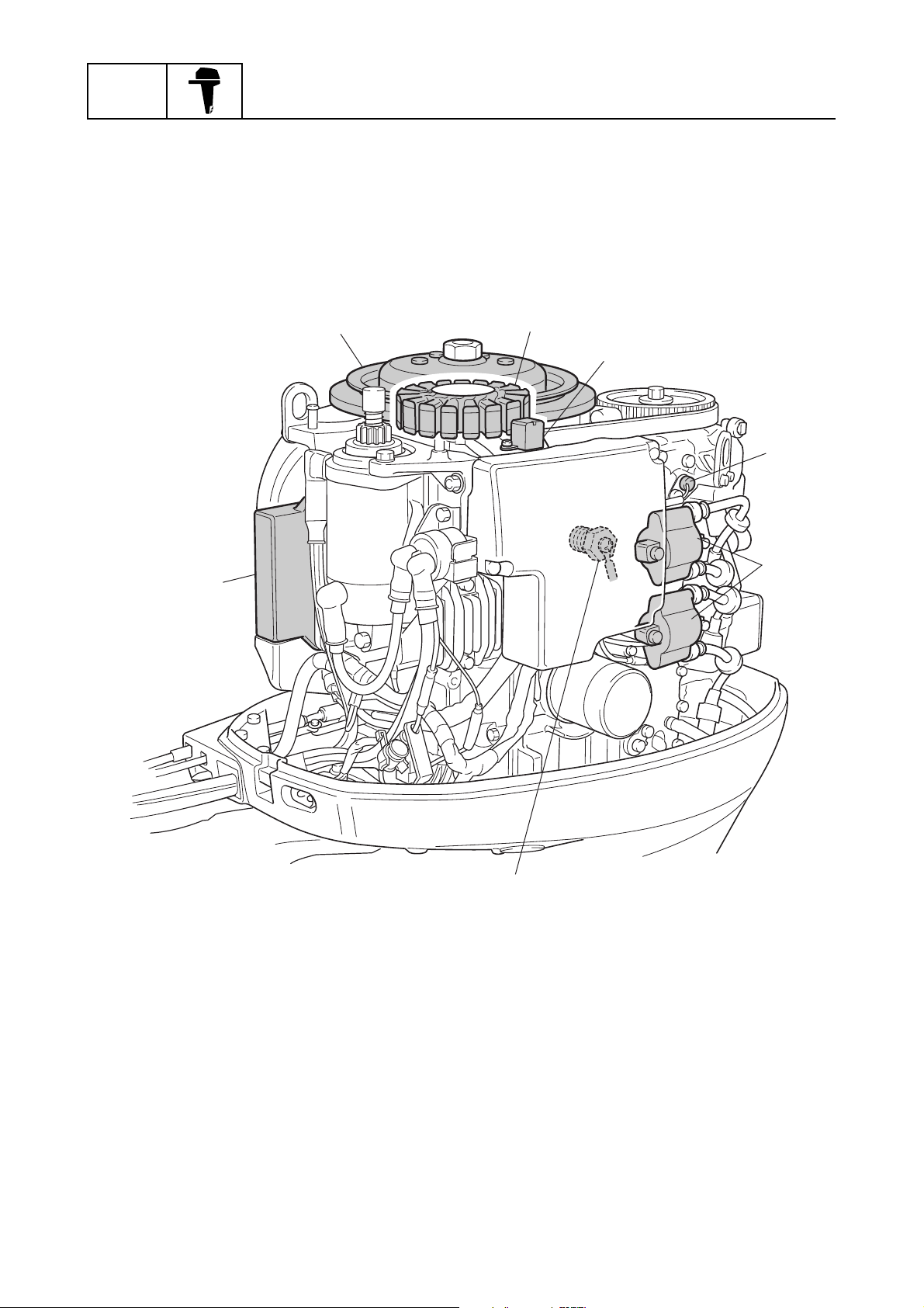
The ignition system consists of a flywheel, stator, pulser coil, thermoswitch, oil pressure switch, CDI
unit, and ignition coil. The CDI unit contains a built-in microcomputer that determines the ignition
timing separately for acceleration and for normal operation, based on signals received from the
pulser coil, thermoswitch, and oil pressure switch.
.
General information
1
2
3
4
5
6
CDI unit
1
Flywheel
2
Stator
3
Pulser coil
4
Thermoswitch
5
Ignition coil
6
Oil pressure switch
7
1-7
7
S62Y1210
62Y3A11
Page 13

Features and benefits
Lower unit
Higher class pinion and gears
The lower unit of the new T50/FT50B, FT50C uses the same type of large gears that are used in the
F100. The use of the same type of gears that are used in a higher class model provides ample durability, making it possible to accommodate a wider range of applications throughout the market.
1
2
3
F50/F50A T50/FT50B, FT50C
Pinion Forward gear Reverse gear
Model
F50/F50A 13 45 24 74 24 75 1.8
T50/FT50B,
FT50C
Number
of teeth
13 46 30 95 30 95 2.3
Diameter
(mm)
Number
of teeth
Diameter
(mm)
Number
of teeth
Diameter
(mm)
S62Y1220
Gear ratio
4
5
6
7
62Y3A11
1-8
8
I
Page 14
GEN
INFO
Shift slider type shift mechanism
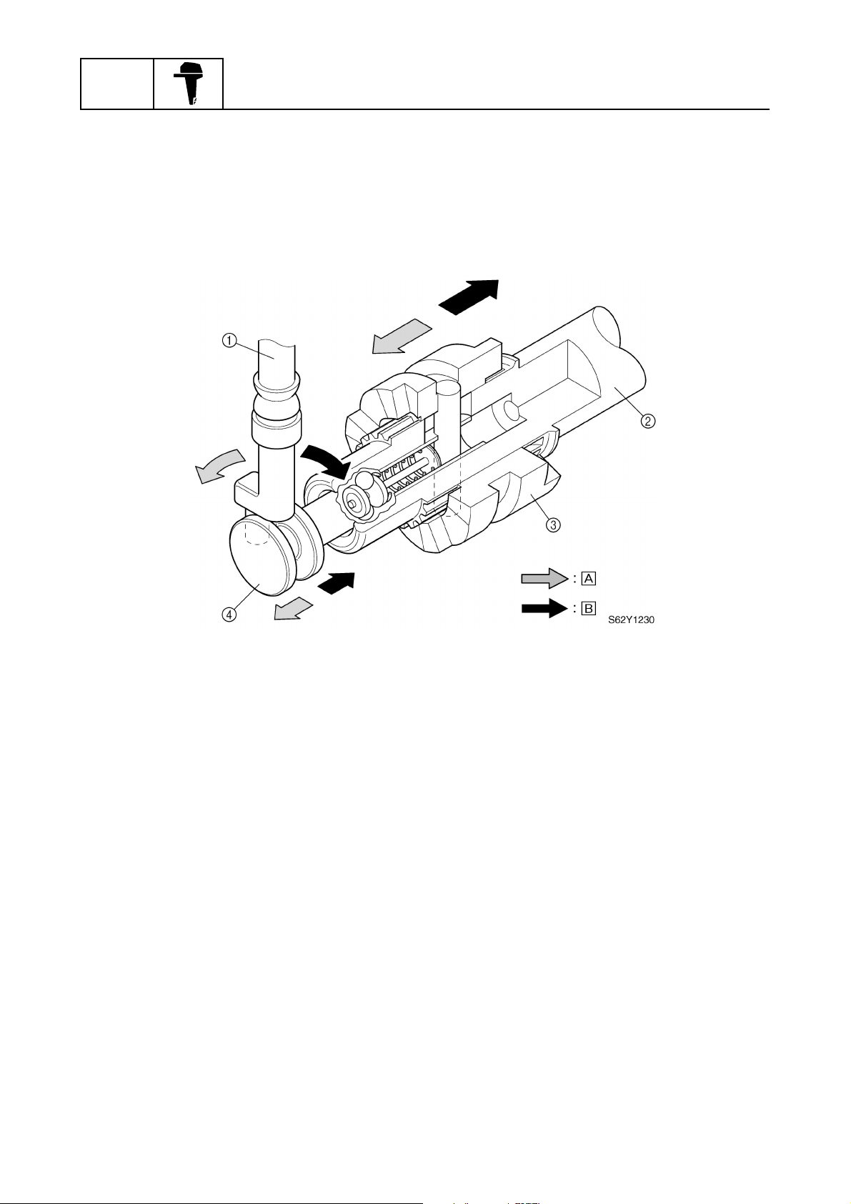
The T50/FT50B, FT50C has adopted the shift slider type shift mechanism. This shift mechanism
enables a prompt engagement of the dog clutch regardless of the operating speed of the shift lever.
Thus, smooth and positive shift operation has been made possible.
General information
Shift rod
1
Propeller shaft
2
Dog clutch
3
Shift slider
4
Forward
È
Reverse
É
1-9
62Y3A11
Page 15

Features and benefits / Technical tips
Technical tips
Carburetor
Starting system (Prime Start)
To facilitate the starting of a cold engine, an air-fuel mixture that is richer than normal is required.
For this reason, the Prime Start system has been adopted in the F50/F50A, T50/FT50B, FT50C. In
the Prime Start system, the thermo heater plunger is in a position that fully opens the fuel enrichment valve while the engine is being started. Thus, fuel enrichment is achieved during the starting of
the engine, and continues while the engine is being warmed up. Once the engine starts, current
flows from the lighting coil of the to the thermo heater, allowing the wax in the Prime Start unit to
expand. The expanded wax moves the thermo heater plunger in the direction to close the enrichment valve. As a result, the volume of fuel that passes through the fuel enrichment valve decreases.
A few minutes after the engine has started, the thermo heater plunger completely closes the fuel
enrichment valve, thus ending the fuel enrichment by the Prime Start system.
1
1
1
2
3
7
6
4
3
2
4
5
6
:
:
:
7
Prime Start
1
Intake manifold of the engine
2
Thermo heater plunger
3
Fuel enrichment valve
4
To carburetor #2 or #4
5
62Y3A11
5
Carburetor
6
Intake silencer
7
Air
È
Fuel
É
Plunger movement
Ê
S62Y1240
1-10
8
I
Page 16

GEN
INFO
General information
Prime Start
1
The enriched air-fuel mixture is delivered to
È
cylinders #1 and #2 by the Prime Start system
attached to carburetor #1.
The enriched air-fuel mixture is delivered to
É
cylinders #3 and #4 by the Prime Start system
attached to carburetor #3.
1-11
62Y3A11
Page 17

Technical tips
Carburetor operation
1. Idle and low-speed operation
Since the vacuum at the venturi is low when the throttle valve is opened slightly, the main nozzle
does not supply any air-fuel mixture to the engine.
When the engine is operating at idle, the fuel that passes through the pilot jet and the air that passes
through the pilot air jet mix, enabling the air-fuel mixture that has been regulated by the pilot screw
to be fed through the pilot outlet.
Because the throttle valve opens slightly when the engine is operating at low speeds, air-fuel mixture also starts to be fed from the bypass holes.
3
3
2
2
2
2
:
:
:
:
:
:
1
2
3
Pilot screw
1
Pilot outlet
2
Bypass holes
3
Venturi
4
Main nozzle
5
Pilot jet
6
Main jet
7
Pilot air jet
8
1
1
0
0
9
9
8
8
7
7
9
0
È
É
Ê
6
6
Main air jet
Throttle valve
Air
Air-fuel mixture
Fuel
5
5
3
3
S62Y1260
S62Y1260
4
4
4
5
6
7
8
62Y3A11
1-12
I
Page 18

GEN
INFO
2. Medium speed operation
When the throttle valve opens further, air-fuel mixture is fed from the pilot outlet and all the bypass
holes. In addition, air-fuel mixture is also supplied from the main nozzle in accordance with the
opening angle of the throttle valve.
General information
3
2
2
:
:
:
0
3
1
4
9
8
5
7
6
S62Y1270
Pilot screw
1
Pilot outlet
2
Bypass holes
3
Venturi
4
Pilot jet
5
Main jet
6
Main nozzle
7
Pilot air jet
8
1-13
Main air jet
9
Throttle valve
0
Air
È
Air-fuel mixture
É
Fuel
Ê
62Y3A11
Page 19

Technical tips
3. High-speed operation
When the throttle valve approaches its fully open position, the fuel that has been regulated by the
main jet and the air that has been regulated by the main air jet are mixed in the main nozzle. The
resultant mixture is then sprayed by the main nozzle into the venturi. The air-fuel mixture that is
sprayed through the venturi is then fed into the engine.
:
:
:
2
3
1
2
3
8
1
7
6
5
4
5
4
6
S62Y1280
7
Pilot screw
1
Pilot outlet
2
Bypass holes
3
Main nozzle
4
Pilot jet
5
Main jet
6
Main air jet
7
Throttle valve
8
62Y3A11
Air
È
Air-fuel mixture
É
Fuel
Ê
1-14
8
I
Page 20

GEN
INFO
Acceleration pump
The function of the acceleration pump is to ensure a smooth acceleration by preventing the air-fuel
mixture from becoming temporarily lean in case the throttle valve is opened suddenly. When the
throttle valve is opened suddenly, a large volume of air is introduced into the engine. However,
because fuel is heavier than air, it is not possible to supply the volume of fuel that is necessary for
the large volume of air that has been introduced. Thus, because it is not possible to achieve the airfuel mixture that is required by the engine, bucking or hesitation results. For this reason, the acceleration pump temporarily increases the fuel volume in order to adjust the air-fuel mixture to a ratio that
is necessary for the engine in case the throttle valve is opened suddenly.
General information
:
:
Bypass hose
1
Acceleration pump
2
Pump chamber
3
Diaphragm 1
4
Throttle lever
5
Air flow
È
Throttle valve opening direction
É
5
1
2
3
4
S62Y1290
1-15
62Y3A11
Page 21

Technical tips
Operation
When the throttle is opened suddenly, diaphragm 1 (via the link that is connected to the throttle
lever) operates to pressurize the air in the pump chamber. The pressurized air opens diaphragm 2,
and becomes distributed to the carburetors by passing through the pipes that are connected to the
carburetors. The pressurized and distributed air then utilizes the passage of the main air jet to flow
into the main nozzle. The pressure of the air helps suck fuel from the main jet, which increases the
fuel in the main nozzle, and thus achieves the fuel enrichment.
1
:
:
1
2
3
5
4
8
6
1
2
3
2
7
3
4
90
A
A
5
Main air jet
1
Main nozzle
2
Main jet
3
Throttle valve
4
Pilot screw
5
Pilot outlet
6
Pilot jet
7
From acceleration pump
8
Throttle valve closing
9
Throttle valve opening
0
62Y3A11
B
B
Diaphragm 1
A
Diaphragm 2
B
To carburetors
C
Air flow
È
Throttle valve opening direction
É
C
S62Y1300
1-16
6
7
8
I
Page 22

GEN
INFO
Ignition system
In order to determine the optimal ignition timing that is necessary for the proper operation of the
engine, the built-in microcomputer in the CDI unit detects the signals from various types of sensors
and controls the ignition timing in accordance with a control map that is based on those signals. The
microcomputer also effects controls to protect the engine against overheating, over-revolution, and
oil pressure drops, as well as to control warning devices.
General information
Pulser coil
1
Flywheel
2
Charge coil
3
CDI unit
4
Microcomputer
5
1
2
3
8
9
4
5
Ignition coils #1 and #4
6
Ignition coils #2 and #3
7
Oil pressure switch
8
Thermoswitch
9
6
7
S62Y1310
Flywheel
Three protrusions for the pulser coil are provided along the periphery of the flywheel. The purpose
of these protrusions is for detecting the engine speed. Two of them are used for ignition signals, and
one is used for identifying the cylinders, and these signals are transmitted to the microcomputer.
1-17
62Y3A11
Page 23

Technical tips
Pulser coil
The pulser coil transmits the pulser signals, which are generated in the pulser coil in accordance
with the rotation of the flywheel, to the CDI unit. Among the two protrusions that are provided for
generating signals, one is used for cylinders #1 and #4, and the other for cylinders #2 and #3, thus
enabling the pulser coil to simultaneously ignite two cylinders.
To provide ignition signals to the cylinders, the microcomputer determines the ignition cylinder and
ignition timing. These are based on the cylinder identification signals generated by the protrusion for
identifying cylinders, and on the pulser signals generated by the protrusions for generating ignition
signals.
1
Flywheel
1
Rotating direction
2
Protrusion for cylinders #1 and #4
3
Pulser coil
4
Cylinder identification protrusion
5
Protrusion for cylinders #2 and #3
6
1
6
2
3
5
2
4
3
4
S62Y1320
5
6
62Y3A11
1-18
7
8
I
Page 24

GEN
INFO
Ignition timing control
Control circuit diagram
General information
Operation
Engine start
Acceleration
Over-revolution
Low oil pressure
Overheat
Detection Microcomputer
Engine temperature
Engine speed
Oil pressure
Ignition timing control
(optimized ignition
timing)
Engine speed control
Warning buzzer
(in remote-control
unit)
Warning lamp
(low oil pressure)
Warning lamp
(to overheat)
Positive start
Quick acceleration
Damage prevention
S62Y1330
Basic control
The ignition timing is determined by using the map based on the engine speed (r/min). Then, ignition signals are output from the microcomputer in accordance with the ignition timing map so that
ignition can take place at the optimal timing in relation to the engine speed. Then, the microcomputer corrects the ignition timing in accordance with the operating conditions of the engine as
detected by the signals that are input from the engine temperature sensor and oil pressure sensor.
The pulser signals that are output when the protrusions for cylinders #1 and #4, and for cylinders #2
and #3 pass by the pulser coil, are used to calculate the engine speed. In addition, the pulser signals are used to determine the forecast starting position of the ignition timing.
9
1
5
Cylinder identification protrusion
1
Pulser coil
2
Protrusion for cylinders #1 and #4
3
Protrusion for cylinders #2 and #3
4
Pulser coil signal
5
1-19
2
34
6
7
8
Cylinder identification signal
6
Identification signal for cylinders #1 and #4
7
Identification signal for cylinders #2 and #3
8
Rotating direction
9
S62Y1340
62Y3A11
Page 25

Technical tips
Starting control
When starting the engine, the timing is set to 5° BTDC until the crankshaft speed maintains 600
r/min for two seconds or longer.
3
9
1
5
Cylinder identification protrusion
1
Protrusion for cylinders #1 and #4
2
Pulser coil
3
Protrusion for cylinders #2 and #3
4
Pulser coil signal
5
Cylinder identification signal
6
Warm-up control
After the starting control is completed, the control transfers to the ignition timing based on the warmup map for three minutes. From the time the three-minute warm-up control has been completed, the
control transfers to the normal map.
24
6
7
8
Starting signal (5° BTDC) for cylinders #1 and
7
#4
Starting signal (5° BTDC) for cylinders #2 and
8
#3
Rotating direction
9
S62Y1350
1
2
3
4
1
5
0
Ignition timing (BTDC°)
1
Engine speed (× 1,000 r/min)
2
Warm-up map
3
Acceleration map
4
Normal map
5
3
4
5
123456
2
S62Y1360
5
6
7
8
62Y3A11
1-20
I
Page 26

GEN
INFO
Acceleration control
This control is activated when the throttle valve is opened suddenly. If the engine speed increases
more than the specified figures, the control of the ignition timing transfers to the acceleration map.
Thereafter, the control of the ignition timing transfers gradually to the control map before acceleration. If it was under warm-up control, the timing transfers to the warm-up control map, and if it was
under normal control, the timing transfers to the normal control map. The control described above
will be repeated if the engine is accelerated again.
Over-revolution control
This control operates by detecting the engine speed. If the engine speed increases to over 6,200
r/min, the ignition of cylinders #1 and #4 is stopped in order to regulate the speed. If the engine
speed increases further to over 6,300 r/min, the ignition of cylinders #2 and #3 is also stopped. This
control will not be deactivated until the engine speed drops below 6,200 r/min.
Overheating control
This control operates in accordance with the engine temperature, which is detected by the signal
that is input from the thermoswitch. When the microcomputer detects via the thermoswitch signal
that the engine temperature has increased to over 80 °C (176 °F), it outputs a signal to stop the ignition of cylinders #1 and #4, if the engine speed is over 2,000 r/min. At the same time, the microcomputer issues a warning by operating the warning lamp and the warning buzzer. When the
overheating control is activated, it will not be deactivated until the engine is stopped or the engine
temperature decreases to under 70 °C (158 °F).
The determination of overheating stops when the engine is stopped. However, until the engine temperature decreases to approximately 70 °C (158 °F) or below, the overheating control will be activated upon restarting the engine. Upon restarting, if the engine speed is under 2,000 r/min, the
overheating control will not be activated for 75 seconds. However, if the engine is operated at over
2,000 r/min for more than 25 seconds, the overheating control will be activated.
Oil pressure control
The oil pressure control operates in accordance with the signals from the oil pressure switch. The oil
pressure is determined to have dropped if the engine continues to operate at over 2,000 r/min with
an oil pressure of under 49 kPa (0.49 kgf/cm
pressure control is activated, the warning buzzer sounds and the warning lamp illuminates. If the
engine speed is over 2,000 r/min, the control stops the ignition of cylinders #1 and #4 so that the
engine speed will not increase to over 2,000 r/min. Once an oil pressure drop is determined, this
control will not be deactivated even if the oil pressure recuperates, until the engine is stopped.
General information
2
, 6.97 psi) for more than one second. When the oil
1-21
62Y3A11
Page 27

Technical tips
Power trim and tilt
The newly designed power trim and tilt consists of an up-main valve, a down-main valve, an uprelief valve, a single cylinder, and a single ram, which control both trim and tilt functions.
The power trim and tilt cylinder has been integrated with the gear pump housing, the reservoir tank,
and the power trim and tilt motor in order to achieve a smaller and more compact unit.
Hydraulic system diagram
9
8
1
1
2
2
3
4
5
3
4
6
73
3
S62Y1370
Power trim and tilt cylinder
1
Ram
2
Reservoir
3
Manual valve
4
Down-main valve
5
Down-relief valve
6
Hydraulic pump
7
Up-relief valve
8
Up-main valve
9
5
6
7
8
62Y3A11
1-22
I
Page 28

GEN
INFO
Power trim and tilt components
1
General information
2
3
6
F
5
C
4
9
B
7
A
8
9
0
E
Cylinder
1
Ram
2
Check valve
3
Down-main valve
4
Down-relief valve
5
Motor
6
Gear pump
7
Up-main valve
8
Reservoir
9
Manual valve
0
1-23
D
Up-relief valve
A
Up-shuttle piston
B
Down-shuffle piston
C
Trim cylinder base
D
Free piston
E
Tilt piston
F
S62Y1380
62Y3A11
Page 29

Technical tips
Trim-up function
The gear pump pumps power trim and tilt fluid to the up-main valve. As a result, the fluid pressure
opens the up-shuttle piston causing the fluid to flow into the lower part of the power trim and tilt cylinder. At the same time, vacuum from the gear pump opens the down-main valve and down-shuttle
piston, which causes fluid from the upper part of the power trim and tilt cylinder to return to the gear
pump, and also sucks fluid in through the reservoir.
The pressurized fluid forces up the trim cylinder along with the tilt piston, free piston, and trim cylinder base. As the trim cylinder moves up, the ram extends and the outboard motor is trimmed up.
The end of the trim range is when the trim cylinder tops out in the power trim and tilt cylinder.
Trim-up function
1
2
1
C
2
3
A
4
0
5
8
6
7
9
8
:
:
3
4
5
6
Power trim and tilt cylinder
1
Ram
2
Trim cylinder
3
Down-main valve
4
Motor
5
Gear pump
6
Up-main valve
7
Reservoir
8
62Y3A11
B
Up-shuttle piston
9
Down-shuttle piston
0
Free piston
A
Trim cylinder base
B
Tilt piston
C
Return
È
Send
É
S62Y1390
1-24
7
8
I
Page 30

GEN
INFO
Trim-down function
When the power trim and tilt switch is pressed to “Down”, the motor turns the gear pump counterclockwise and the power trim and tilt fluid flows in the opposite direction to that of the trim-up function.
Tilt-up function
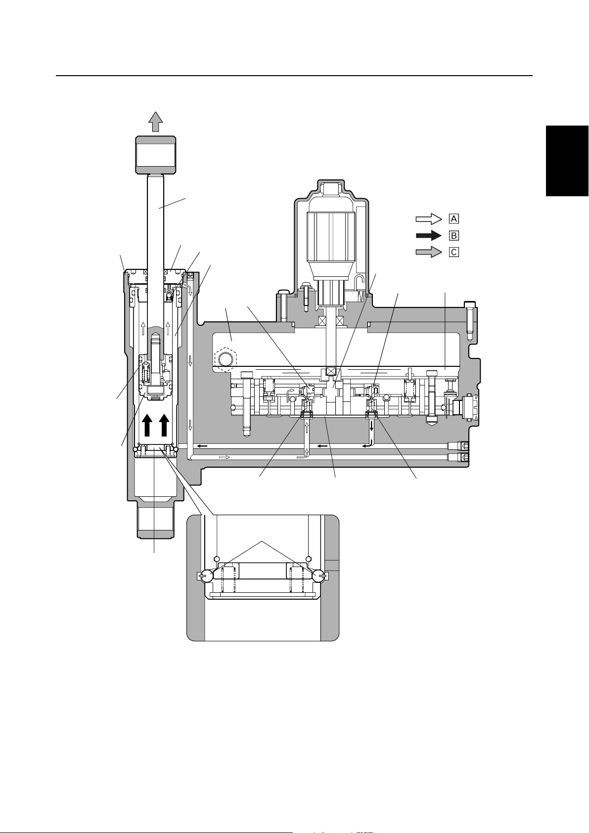
When the trim cylinder tops out, the check valve is pushed down by the end screw wall. This causes
the ball in the check valve to move down, opening the fluid passage and allowing the power trim and
tilt fluid to flow from the upper part of the trim cylinder, through the down-shuttle piston and the
down-main valve, and back to the gear pump. In addition, fluid is also sucked in through the reservoir and the pressurized fluid continues to flow into the lower part of the trim cylinder, pushing up the
tilt piston and free piston, and further extending the ram.
As the tilt piston moves up and off of the trim cylinder base, the base moves up and pushes the balls
outward to fit into holes of the power trim and tilt cylinder. Once the balls have been fitted into the
holes the trim cylinder base cannot move.
The end of the tilt-up range is when the tilt piston tops out in the trim cylinder and the ram is fully
extended.
The tilt-up function operates when the fluid pressure is under 10 MPa (100 kgf/cm
When the fluid pressure in the lower part of the trim cylinder increases to over 10 MPa (100 kgf/cm
1,423 psi), the up-relief valve opens and allows the pressurized fluid to flow into the reservoir. Thus,
the tilt piston and free piston are not pushed up and the ram cannot be extend further.
General information
2
, 1,423 psi).
2
,
1-25
62Y3A11
Page 31
Tilt-up function
1
3
2
4
5
8
Technical tips
:
:
:
1
2
D
C
B
6
7
A
E
6
9
0
6
3
4
5
6
Power trim and tilt cylinder
1
Ram
2
End screw
3
Check valve
4
Trim cylinder
5
Reservoir
6
Down-main valve
7
Gear pump
8
Up-main valve
9
62Y3A11
Up-shuttle piston
0
Down-shuttle piston
A
Trim cylinder base
B
Free piston
C
Tilt piston
D
Balls
E
Return
È
Send
É
Moving direction
Ê
S62Y1400
1-26
7
8
I
Page 32
GEN
INFO
Circular flow
General information
2
4
:
1
9
8
3
5
:
6
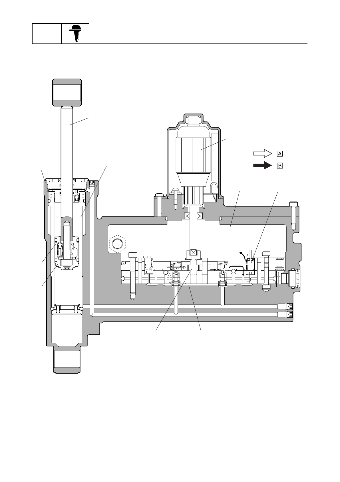
Power trim and tilt cylinder
1
Ram
2
Trim cylinder
3
Motor
4
Reservoir
5
Up-relief valve
6
1-27
7
Gear pump
7
Free piston
8
Tilt piston
9
Return
È
Send
É
5
S62Y1410
62Y3A11
Page 33

Technical tips
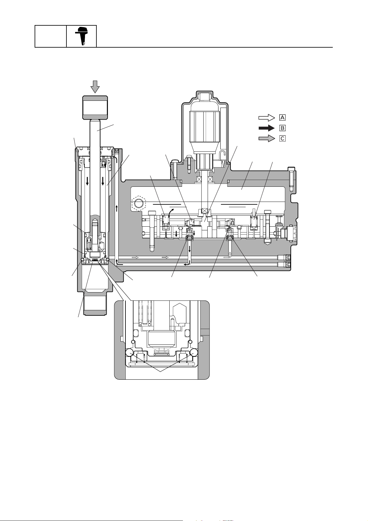
Tilt-down function
When the power trim and tilt switch is pressed to “Down”, the motor turns the gear pump counterclockwise, thus pumping the power trim and tilt fluid to the down-main valve. As a result, fluid pressure opens the down-main valve and the down-shuttle piston, which causes fluid to flow into the
upper part of the trim cylinder and forces the tilt piston down.
When the tilt piston and the free piston reach the trim cylinder base, it pushes the base down, allowing the balls to move inward. Once the balls move in, the trim cylinder is then able to move down
and power trim and tilt fluid continues to flow into the cylinder and pushes the trim cylinder down,
along with the tilt piston and ram.
The end of the tilt-down range is when the tilt piston and the free piston bottom out in the trim cylinder base. When the power trim and tilt fluid pushes the trim cylinder down further trim-down is
started. The end of the trim-down range is when the trim cylinder arrives at the bottom of the power
trim and tilt cylinder. Before the trim cylinder arrives at the bottom of the power trim and tilt cylinder,
an amount of fluid equal to the volume of the ram is returned to the reservoir.
1
2
3
4
5
6
7
62Y3A11
1-28
8
I
Page 34
GEN
INFO
Tilt-down function
1
General information
2
3
5
4
:
:
:
6
78
E
D
B
C
B
F
A
0
9
S62Y1420
Power trim and tilt cylinder
1
Ram
2
Trim cylinder
3
Down-relief valve
4
Down-main valve
5
Gear pump
6
Reservoir
7
Up-relief valve
8
Up-shuttle piston
9
Up-main valve
0
1-29
Down-shuttle piston
A
Ball
B
Trim cylinder base
C
Free piston
D
Tilt piston
E
Balls
F
Return
È
Send
É
Moving direction
Ê
62Y3A11
Page 35

Technical tips
Stopping condition
When the power trim and tilt switch is not pushed (released), the gear pump does not pump the
fluid, the up-main valve and the down-main valve are closed, and the power trim and tilt fluid pressure in the system remains constant. This allows the ram to maintain its position until the power trim
and tilt fluid flows through the system again.
When the outboard motor hits something in the water
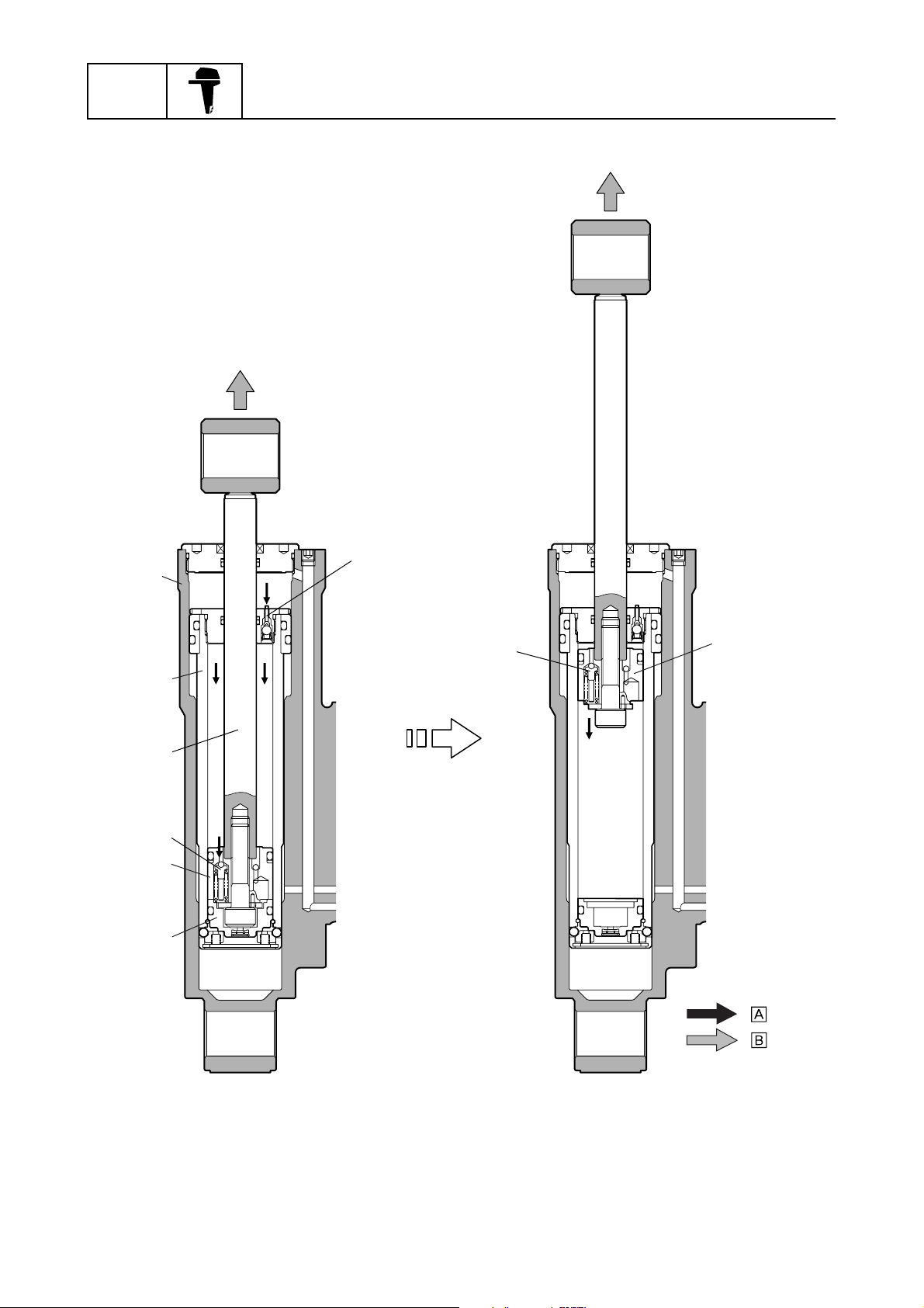
The check valve of the trim cylinder and the tilt piston absorber of the tilt piston help to prevent internal damage to the power trim and tilt unit and help to protect the bracket and lower unit from damage in case the outboard motor hits something during operation.
When the outboard motor hits something, highly pressurized fluid in the upper part of the power trim
and tilt cylinder pushes down the check valve of the trim cylinder. At the same time, fluid pressure in
the upper part of the trim cylinder increases and the tilt piston absorber is pushed down. As a result,
the tilt piston and the ram are pushed up without the free piston. The tilt piston is stopped before
reaching the top of the trim cylinder by the damper function of the tilt piston absorber to protect the
power trim and tilt unit from damage.
1
2
3
4
5
6
7
62Y3A11
1-30
8
I
Page 36
GEN
INFO
Damper function
General information
1
2
3
4
5
6
7
8
9
Power trim and tilt cylinder
1
Trim cylinder
2
Ram
3
Tilt piston absorber
4
Tilt piston
5
Free piston
6
1-31
Check valve
7
Tilt piston absorber
8
Tilt piston
9
Send
È
Moving direction
É
:
:
S62Y1430
62Y3A11
Page 37
Technical tips / Propeller selection
Propeller selection
The performance of a boat and outboard
motor will be critically affected by the size
and type of propeller you choose. Propellers
greatly affect boat speed, acceleration,
engine life, fuel economy, and even boating
and steering capabilities. An incorrect choice
could adversely affect performance and
could also seriously damage the motor.
Use the following information as a guide for
selecting a propeller that meets the operating
conditions of the boat and the outboard
motor.
Propeller size
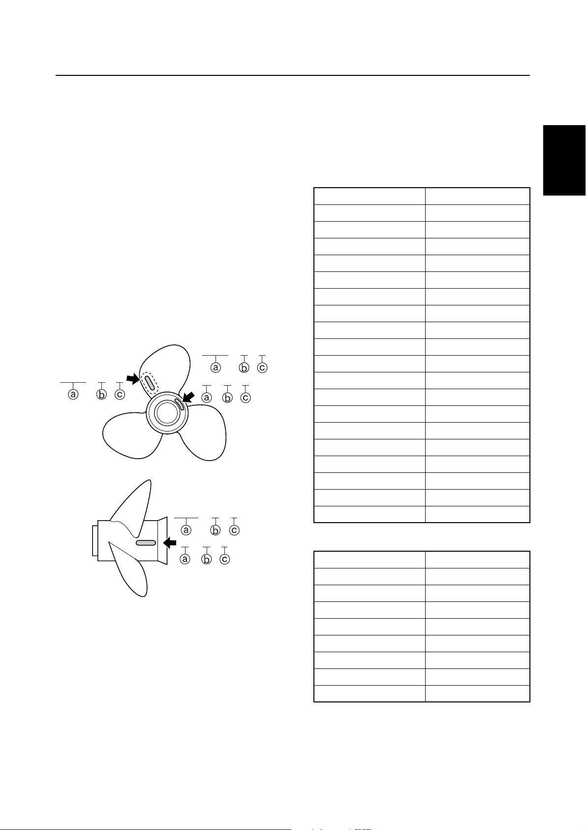
The size of the propeller is indicated on the
propeller blade or outside of the propeller
boss.
10 3/4 × 17 - G
10 3/4 × 17 - G
13 × 19 - K
S62Y1440
10 3/4 × 17 - G
1
Selection
When the engine speed is at the full throttle
operating range (5,000–6,000 r/min) an ideal
propeller for the boat is one that provides
maximum performance in relation to boat
speed and fuel consumption.
F50/F50A
Propeller size (in) Material
10 × 15 - G Aluminum
10 1/4 × 14 - G Aluminum
10 3/8 × 13 - G Aluminum
10 5/8 × 12 - G Aluminum
10 3/4 × 16 - G Aluminum
10 3/4 × 17 - G Aluminum
11 1/8 × 13 - G Aluminum
11 1/4 × 14 - G Aluminum
11 3/8 × 12 - G Aluminum
11 5/8 × 11 - G Aluminum
12 1/4 × 9 - G Aluminum
10 1/4 × 14 - G Stainless
10 1/4 × 15 - G Stainless
10 1/4 × 16 - G Stainless
10 5/8 × 13 - G Stainless
11 1/4 × 14 - G Stainless
11 1/2 × 13 - G Stainless
11 3/4 × 12 - G Stainless
12 × 11 - G Stainless
1
2
3
4
5
Propeller diameter (in inches)
a
Propeller pitch (in inches)
b
Propeller type (propeller mark)
c
62Y3A11
13 × 19 - K
S62Y1450
T50/FT50B, FT50C
Propeller size (in) Material
12 5/8 × 21 - K Aluminum
13 × 19 - K Aluminum
13 × 23 - K Aluminum
13 × 25 - K Aluminum
13 1/4 × 17 - K Aluminum
13 1/2 × 15 - K Aluminum
13 5/8 × 13 - K Aluminum
14 × 11 - K Aluminum
1-32
6
7
8
I
Page 38
GEN
INFO
General information
Predelivery checks
To make the delivery process smooth and
efficient, the predelivery checks should be
completed as explained below.
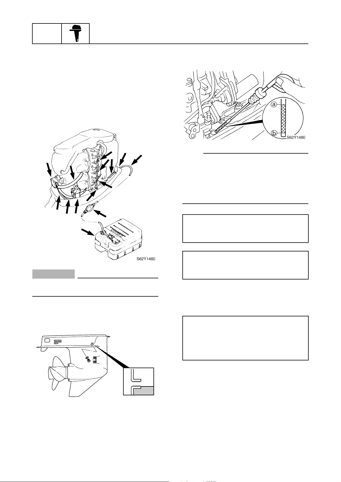
Checking the fuel system
1. Check that the fuel hoses are securely
connected and that the fuel tank is full
with fuel.
1
Checking the engine oil
1. Check the oil level.
NOTE:
• If the engine oil is above the maximum level
mark a, drain sufficient oil until the level is
between a and b.
• If the engine oil is below the minimum level
mark b, add sufficient oil until the level is
between a and b.
CAUTION:
This is a 4-stroke engine. Never use premixed fuel.
Checking the gear oil
1. Check the gear oil level.
Recommended engine oil:
API: SE, SF, SG, SH
SAE: 10W-30, 10W-40, or 20W-40
Oil capacity:
Without oil filter replacement:
2.0 L (2.1 US qt, 1.8 Imp qt)
Checking the battery
1. Check the capacity, electrolyte level, and
specified gravity of the battery.
Battery capacity: 70–100 Ah (252–360 kC)
Minimum cold cranking performance:
380 A
Electrolyte specific gravity:
1.28 at 20 °C (68 °F)
2. Check that the positive and negative bat-
tery leads are securely connected.
1-33
S62Y1470
62Y3A11
Page 39
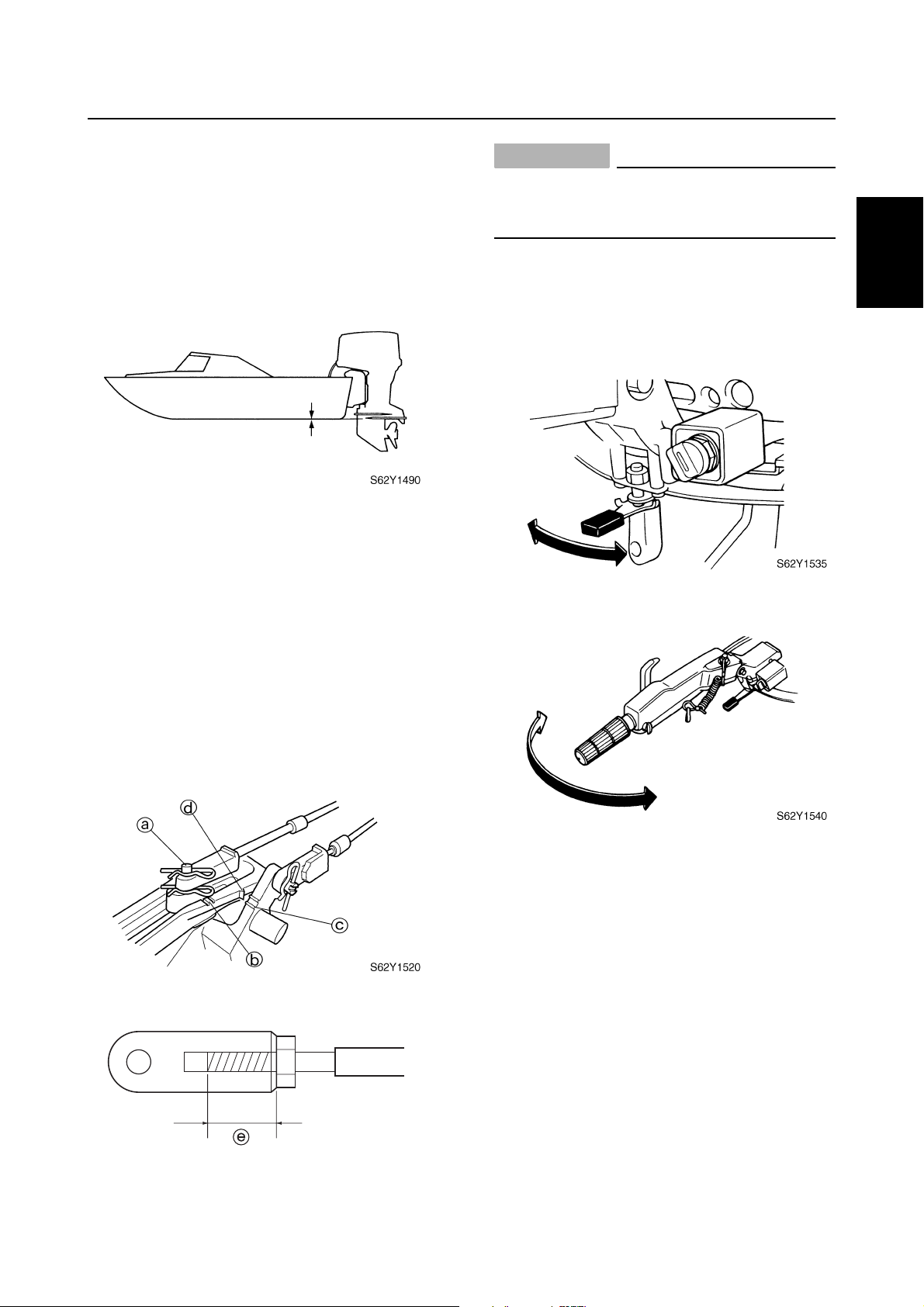
Checking the outboard motor
mounting position
1. Check the position of the anti-cavitation
plate.
2. Check that the clamp brackets are
secured with the clamp bolts.
Predelivery checks
CAUTION:
The shift/throttle cable joint must be
screwed in a minimum of 8.0 mm (0.31 in)
e
.
Checking the steering wheel/tiller
handle
1. Check the steering friction for proper
adjustment.
1
2
Checking the remote control cables
1. Set the remote control lever to the neutral position and fully close the throttle
lever/throttle grip.
2. Check that the set pin a is aligned with
the alignment mark b. Adjust if necessary.
3. Check that the alignment mark c is
aligned with the mark d. Adjust if necessary.
2. Check the steering for smooth operation.
3. Check that there is no interference with
wires or hoses when the outboard motor
is steered.
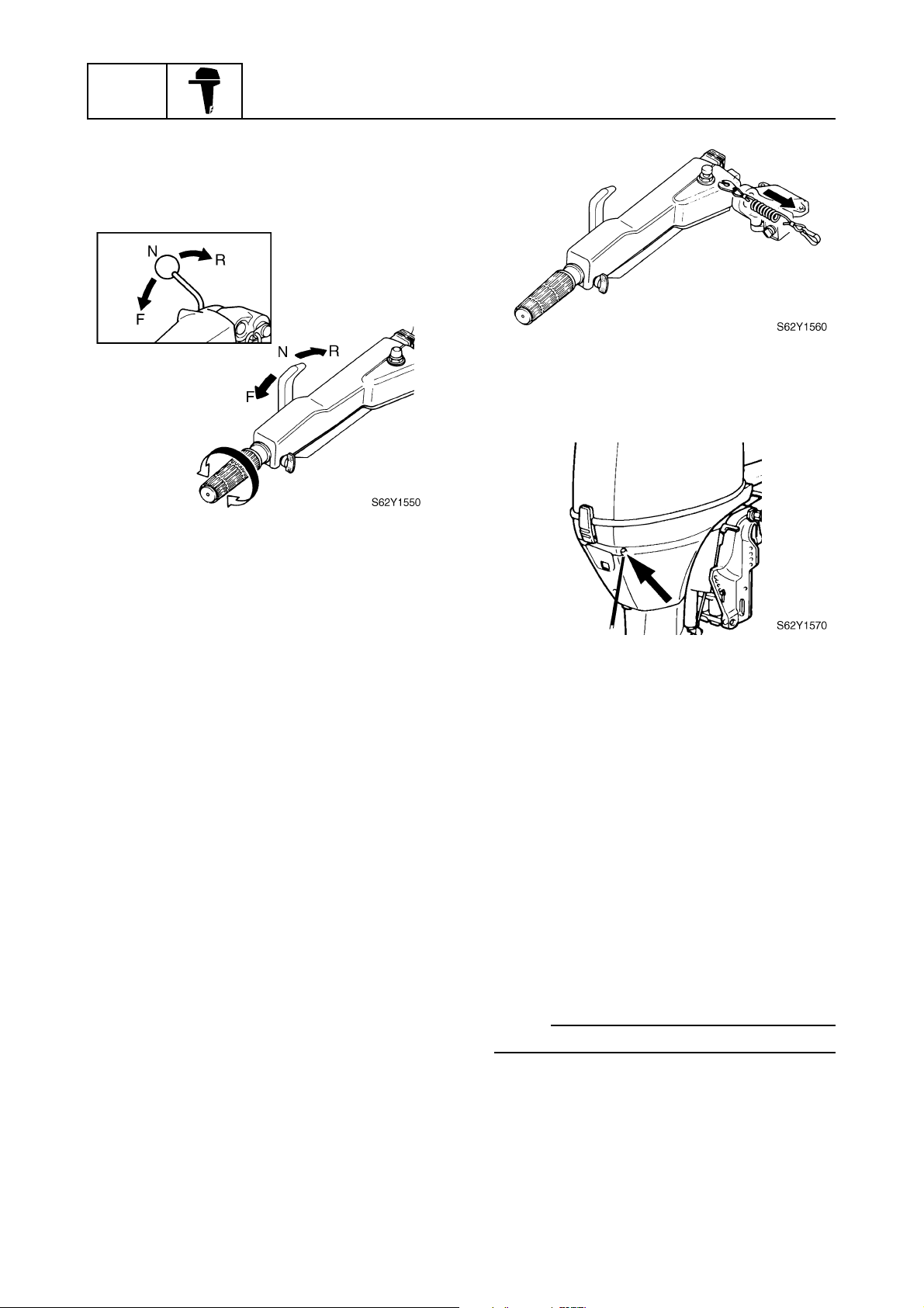
Checking the gearshift and throttle
operation
1. Check that the gearshift operates
smoothly when shifting from neutral into
forward and reverse.
3
4
5
6
7
62Y3A11
S62Y1530
1-34
8
I
Page 40
GEN
INFO
2. Check that the throttle control lever contacts the respective stoppers when the
throttle control lever is closed or fully
open.
General information
Checking the pilot water outlet
1. Check that cooling water is discharged
from the pilot water outlet.
Checking the tilt system
1. Check that the outboard motor can be
smoothly tilted up and down by operating
the power trim and tilt unit.
2. Check that there is no abnormal noise
produced when the outboard motor is
tilted up and down.
3. Check that there is no interference with
wires and hoses when the tilted-up motor
is steered.
4. Check that the trim meter points down
when the outboard motor is tilted all the
way down.
Checking the engine start switch and
engine stop switch/engine shut-off
switch
1. Check that the engine starts when the
engine start switch is turned to START.
2. Check that the engine turns off when the
engine start switch is turned to OFF.
Test run
1. Start the engine, and then check for
smooth gearshift operation.
2. Check the engine idle speed after the
engine has been warmed up.
3. Operate at trolling speed.
4. Run the outboard for one hour at 2,000
r/min or at half throttle, then for another
hour at 3,000 r/min or at 3/4 throttle.
5. Check that the motor will not tilt up when
shifting into reverse and that water will
not flow in over the transom.
NOTE:
The test run is part of the break-in operation.
3. Check that the engine turns off when the
engine stop switch is pushed/engine
shut-off cord is pulled.
1-35
62Y3A11
Page 41
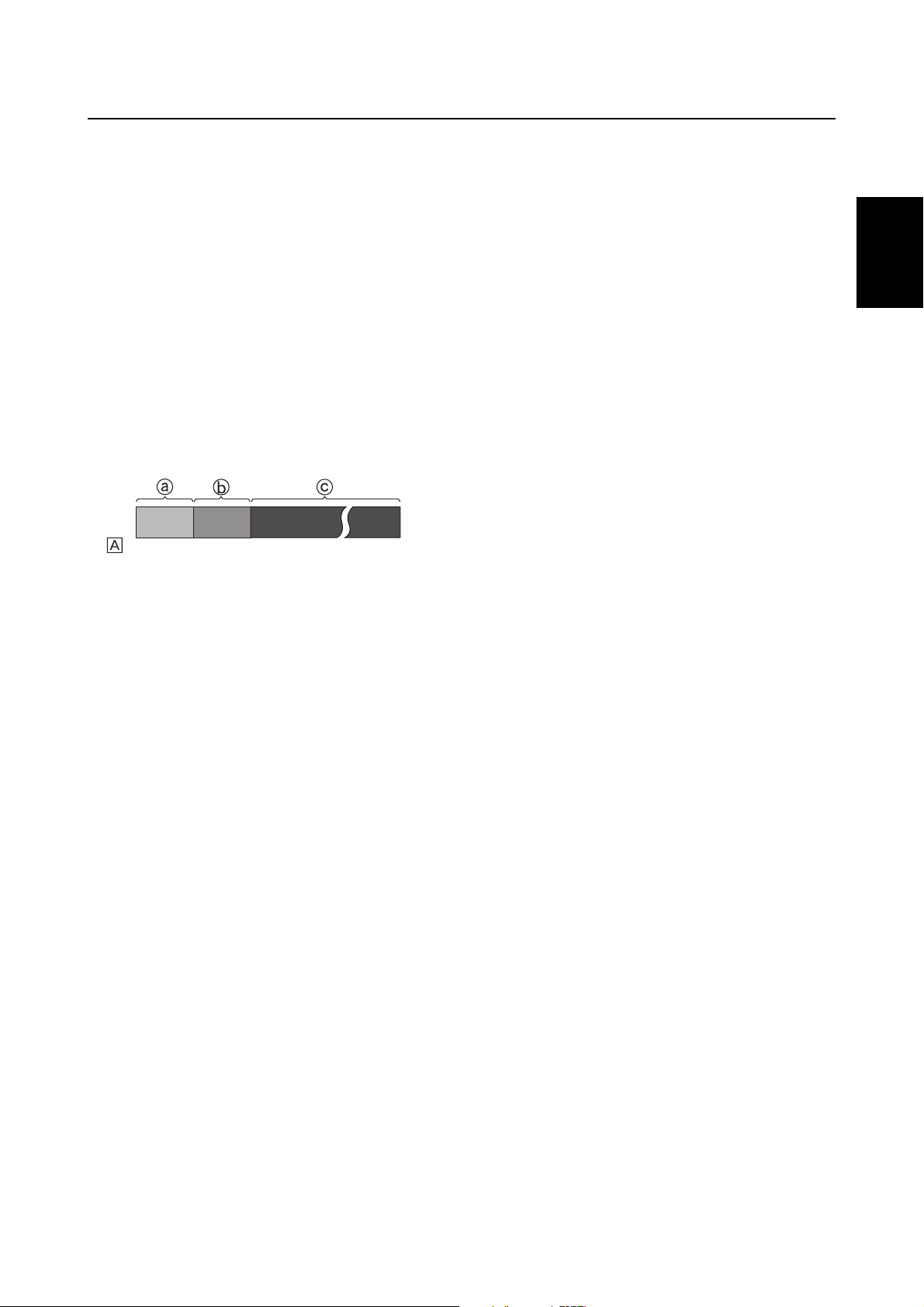
Break-in
In the test run, the break-in operation is performed in the following three stages.
1. One hour a at 2,000 r/min or at approximately half throttle.
Predelivery checks
2. One hour b at 3,000 r/min or 3/4 throttle
and one minute out of every ten at full
throttle.
3. Eight hours c at any speed, however,
avoid running at full speed for more than
five minutes.
0
È
Hour
After test run
1. Check for water in the gear oil.
1
210
S62Y1580
1
2
3
4
2. Check for fuel leakage in the cowling.
3. After a test run and while the engine is at
idle, flush the cooling water passage with
fresh water using the flushing kit.
5
6
7
8
62Y3A11
1-36
I
Page 42
GEN
INFO
General information
— MEMO —
1-37
62Y3A11
Page 43
SPEC
Specifications
General specifications...................................................................................2-1
Maintenance specifications ..........................................................................2-5
Power unit..................................................................................................2-5
Lower unit ..................................................................................................2-9
Electrical ....................................................................................................2-9
Power unit................................................................................................2-12
Lower unit ................................................................................................2-16
Electrical ..................................................................................................2-16
Dimensions..............................................................................................2-19
Tightening torques.......................................................................................2-29
Specified torques.....................................................................................2-29
General torques.......................................................................................2-31
1
2
3
4
5
6
7
62Y3A11
8
I
Page 44
SPEC
Specifications
General specifications
Model
Item Unit
Dimension
Overall length mm (in) 1,329 (52.3) 718 (28.3)
Overall width mm (in) 361 (14.2)
Overall height
(L) mm (in) 1,397 (55.0)
(X) mm (in) — 1,511
Boat transom height
(L) mm (in) 508 (20.0)
(X) mm (in) — 635 (25.0) — 635 (25.0)
Weight
(with aluminum propeller)
(L) kg (lb) 108 (238) 112 (247) 104 (229) 108 (238)
(X) kg (lb) — 115.5
Performance
Maximum output kW (hp)
Full throttle operating range r/min 5,000–6,000
Maximum fuel consumption L (US gal,
Power unit
Type In-line, 4-stroke, OHC, 8 valves
Cylinder quantity 4
Displacement cm
Bore × stroke mm (in) 63.0 × 75.0 (2.48 × 2.95)
Compression ratio 9.3
Carburetor quantity 4
Control system Tiller handle Remote control
Starting system Electric
Ignition control system Microcomputer (CDI)
Ignition timing Degree BTDC 5 ± 3–BTDC 35 ± 3
Alternator output V, A 12, 10
Enrichment system Prime Start
Choke valve control —
Spark plugs DPR6EA-9 (NGK)
Cooling system Water
Exhaust system Through propeller boss
Lubrication system Wet sump
USA ———F50TR
Canada — F50TH — F50TR
Worldwide F50AEHD F50AEHT F50AED F50AET
— 1,511
(59.5)
— 111.5
(255)
36.8 (50)
@ 5,500 r/min
17.3 (4.57, 3.81)
lmp gal)/hr
@ 6,000 r/min
3
(cu. in) 935 (57.1)
2
(59.5)
(246)
2-1
62Y3A11
Page 45

General specifications
Model
Item Unit
Fuel and oil
Fuel type Regular unleaded gasoline
Fuel rating *PON
Engine oil type 4-stroke motor oil
Engine oil grade API
Engine oil quantity
(with oil filter replacement)
(without oil filter replacement)
Gear oil type Hypoid gear oil
Gear oil grade API
Gear oil quantity
Bracket
Trim angle
(at 12 degree boat transom)
Tilt-up angle Degree 69
Steering angle Degree 40 + 40
Drive unit
Gear shift positions F-N-R
Gear ratio 1.85 (24/13)
Reduction gear type Spiral bevel gear
Clutch type Dog clutch
Propeller shaft type Spline
Propeller direction
(rear view)
Propeller identification mark G
Electrical
Battery capacity Ah (kC) 70–100 (252–360)
Minimum cold cranking
performance
USA ———F50TR
Canada — F50TH — F50TR
Worldwide F50AEHD F50AEHT F50AED F50AET
86
RON
SE, SF, SG, SH
SAE
L
(US qt, lmp qt)
L
(US qt, lmp qt)
SAE
L
(US qt, lmp qt)
Degree –4–20
A 380
10W-30, 10W-40, or 20W-40
0.43 (0.45, 0.38)
91
2.2 (2.3, 1.9)
2.0 (2.1, 1.8)
GL-4
90
Clockwise
1
2
3
4
5
6
7
* PON: Pump Octane Number (Research Octane Number + Motor Octane Number)/2
RON: Research Octane Number
62Y3A11
2-2
8
I
Page 46
SPEC
Specifications
Model
Item Unit
Dimension
Overall length mm (in) 718
Overall width mm (in) 361 (14.2)
Overall height
(L) mm (in) 1,436 (56.5)
Boat transom height
(L) mm (in) 508 (20.0)
Weight
(with aluminum propeller)
(L) kg (lb) 112 (247) 111.5 (246) 108 (238) 112 (247)
Performance
Maximum output kW (hp)
Full throttle operating range r/min 5,000–6,000
Maximum fuel consumption L (US gal,
Power unit
Type In-line, 4-stroke, OHC, 8 valves
Cylinder quantity 4
Displacement cm
Bore × stroke mm (in) 63.0 × 75.0 (2.48 × 2.95)
Compression ratio 9.3
Carburetor quantity 4
Control system Remote
Starting system Electric
Ignition control system Microcomputer (CDI)
Ignition timing Degree BTDC 5 ±
Alternator output V, A 12, 10
Enrichment system Prime Start
Choke valve control —
Spark plugs DPR6EA-9 (NGK)
Cooling system Water
Exhaust system Through propeller boss
Lubrication system Wet sump
USA T50TR ———
Canada T50TR ———
Worldwide FT50BET FT50CEHD FT50CED FT50CET
1,384
(28.3)
@ 5,500 r/min
lmp gal)/hr
@ 6,000 r/min
3
(cu. in) 935 (57.1)
control
3–BTDC
35 ± 3
(54.5)
17.3 (4.57, 3.81)
Tiller
handle
36.8 (50)
BTDC 5 ± 3–BTDC 25 ± 3
BTDC 5 ± 3–BTDC 35 ± 3
(Depending on market)
718 (28.3)
Remote control
2-3
62Y3A11
Page 47
General specifications
Model
Item Unit
Fuel and oil
Fuel type Regular unleaded gasoline
Fuel rating *PON
Engine oil type 4-stroke motor oil
Engine oil grade API
Engine oil quantity
(with oil filter replacement)
(without oil filter replacement)
Gear oil type Hypoid gear oil
Gear oil grade API
Gear oil quantity
Bracket
Trim angle
(at 12 degree boat transom)
Tilt-up angle Degree 69
Steering angle Degree 40 + 40
Drive unit
Gear shift positions F-N-R
Gear ratio 2.33
Reduction gear type Spiral bevel gear
Clutch type Dog clutch
Propeller shaft type Spline
Propeller direction
(rear view)
Propeller identification mark K
Electrical
Battery capacity Ah (kC) 70–100 (252–360)
Minimum cold cranking
performance
USA T50TR ———
Canada T50TR ———
Worldwide FT50BET FT50CEHD FT50CED FT50CET
86
RON
SE, SF, SG, SH
SAE
L
(US qt, lmp qt)
L
(US qt, lmp qt)
SAE
L
(US qt, lmp qt)
Degree –4–20
(28/12)
A 380
10W-30, 10W-40, or 20W-40
0.61 (0.64, 0.54)
91
2.2 (2.3, 1.9)
2.0 (2.1, 1.8)
GL-4
90
2.31 (30/13)
Clockwise
1
2
3
4
5
6
7
* PON: Pump Octane Number (Research Octane Number + Motor Octane Number)/2
RON: Research Octane Number
62Y3A11
2-4
8
I
Page 48
SPEC
Specifications
Maintenance specifications
Power unit
Model
Item Unit
Power unit
Minimum compression
pressure*
Lubrication oil pressure
at 55 °C (131 °F), with
10W-30 engine oil
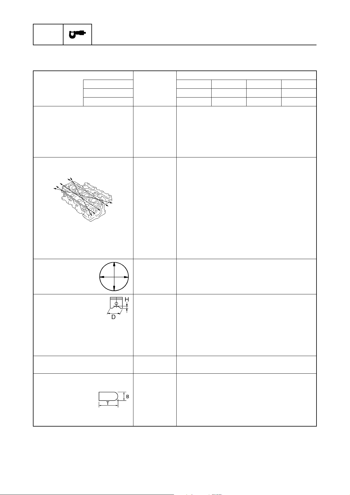
Cylinder heads
Warpage limit mm (in) 0.1 (0.004)
USA ———F50TR
Canada — F50TH — F50TR
Worldwide F50AEHD F50AEHT F50AED F50AET
kPa
(kgf/cm
kPa
(kgf/cm
2
, psi)
2
, psi)
840 (8.4, 119)
100 (1.0, 14)
@ 900 r/min
2
(lines indicate straightedge
position)
Cylinder head journal inside
mm (in) 37.00–37.02 (1.4567–1.4575)
diameter
Cylinders
Bore size mm (in) 63.00–63.01 (2.480–2.481)
Taper limit mm (in) 0.08 (0.003)
Out-of-round limit mm (in) 0.05 (0.002)
Pistons
Piston diameter (D) mm (in) 62.95–62.96 (2.478–2.479)
Measuring point (H) mm (in) 5 (0.2)
Piston-to-cylinder clearance mm (in) 0.04–0.06 (0.0016–0.0024)
Oversize piston diameter
1st mm (in) + 0.25 (0.01)
2nd mm (in) + 0.50 (0.02)
Piston pins
Outside diameter mm (in) 15.965–15.970 (0.6285–0.6287)
Piston rings
Top ring
Dimension B mm (in) 1.17–1.19 (0.046–0.047)
Dimension T mm (in) 2.39–2.41 (0.094–0.095)
End gap mm (in) 0.15–0.30 (0.006–0.012)
Side clearance mm (in) 0.04–0.08 (0.0016–0.003)
* Measuring conditions:
Ambient temperature 20 °C (68 °F), wide open throttle, with plugs disconnected from all cylinders.
The figures are for reference only.
2-5
62Y3A11
Page 49
Maintenance specifications
Model
Item Unit
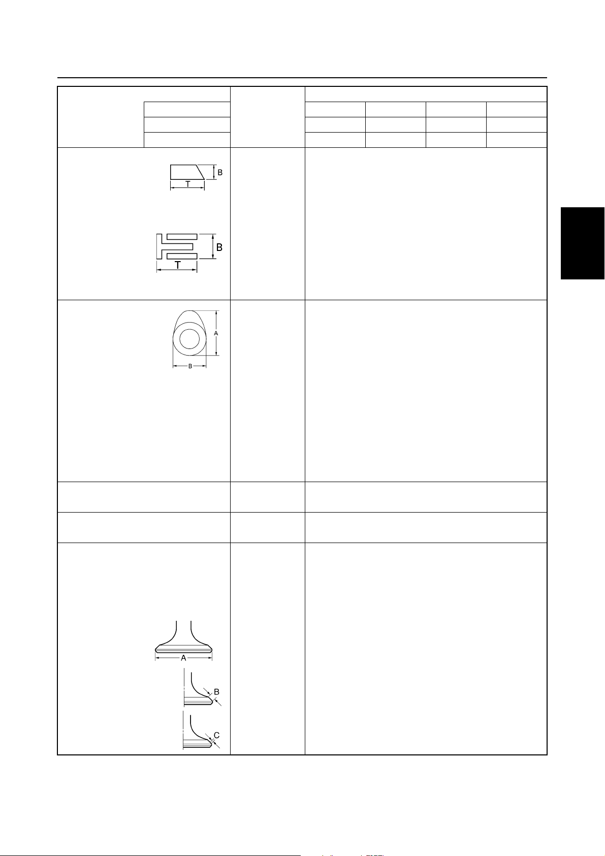
2nd ring
Dimension B mm (in) 1.47–1.49 (0.058–0.059)
Dimension T mm (in) 2.49–2.51 (0.098–0.099)
End gap mm (in) 0.30–0.50 (0.012–0.020)
Side clearance mm (in) 0.03–0.07 (0.001–0.003)
Oil ring
Dimension B mm (in) 2.34–2.46 (0.092–0.097)
Dimension T mm (in) 2.75 (0.108)
End gap mm (in) 0.20–0.70 (0.008–0.028)
Side clearance mm (in) 0.05–0.19 (0.002–0.008)
Camshafts
Intake (A) mm (in) 30.89–30.99 (1.2161–1.2200)
Exhaust (A) mm (in) 30.82–30.92 (1.2135–1.2175)
Intake and
exhaust (B)
Camshaft journal diameter
#1 mm (in) 36.93–36.94 (1.4539–1.4543)
#2, #3, #4 mm (in) 36.94–36.95 (1.4543–1.4547)
Camshaft journal oil clearance
#1 mm (in) 0.055–0.100 (0.0022–0.0039)
#2, #3, #4 mm (in) 0.045–0.090 (0.0018–0.0035)
Maximum camshaft runout mm (in) 0.04 (0.0016)
Rocker arm shafts
Outside diameter mm (in) 15.98–15.99 (0.6291–0.6295)
Rocker arms
Inside diameter mm (in) 16.00–16.01 (0.6299–0.6303)
Valves
Valve clearance (cold)
Intake mm (in) 0.20 ± 0.05 (0.008 ± 0.002)
Exhaust mm (in) 0.30 ± 0.05 (0.012 ± 0.002)
Head diameter (A)
Intake mm (in) 29.9–30.1 (1.177–1.185)
Exhaust mm (in) 25.9–26.1 (1.020–1.027)
USA ———F50TR
Canada — F50TH — F50TR
Worldwide F50AEHD F50AEHT F50AED F50AET
mm (in) 25.95–26.05 (1.0217–1.0256)
1
2
3
4
5
6
7
Face width (B)
Intake mm (in) 1.84–2.97 (0.072–0.117)
Exhaust mm (in) 1.98–3.11 (0.078–0.122)
Seat contact width (C)
Intake mm (in) 0.9–1.1 (0.035–0.043)
Exhaust mm (in) 0.9–1.1 (0.035–0.043)
62Y3A11
2-6
8
I
Page 50
SPEC
Specifications
Model
Item Unit
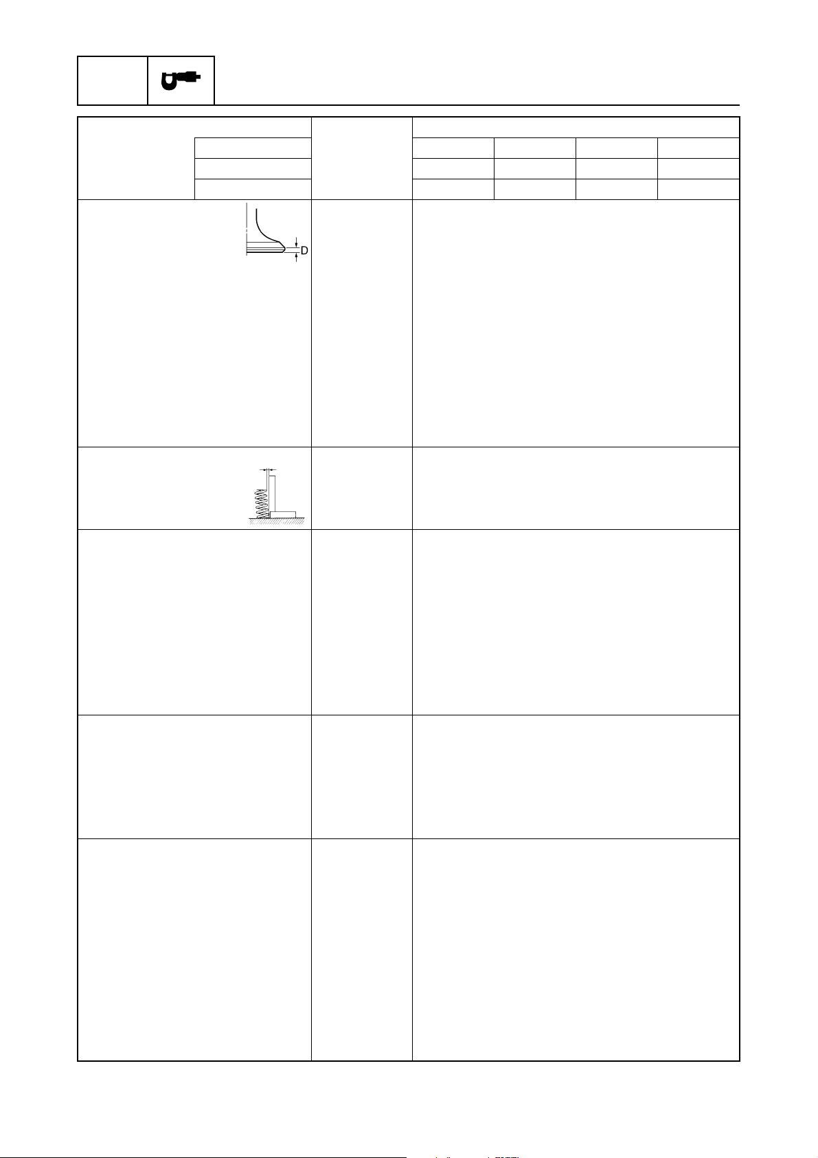
Margin thickness (D)
Intake mm (in) 0.6–1.0 (0.024–0.039)
Exhaust mm (in) 0.7–1.1 (0.028–0.043)
Stem diameter
Intake mm (in) 5.48–5.49 (0.2157–0.2161)
Exhaust mm (in) 5.46–5.47 (0.2150–0.2153)
Guide inside diameter
Intake and exhaust mm (in) 5.50–5.51 (0.2165–0.2169)
Stem-to-guide clearance
Intake mm (in) 0.01–0.03 (0.0004–0.0012)
Exhaust mm (in) 0.03–0.05 (0.0012–0.0020)
Stem runout limit mm (in) 0.03 (0.0012)
Valve springs
Free length mm (in) 39.85 (1.569)
Minimum free length mm (in) 37.85 (1.490)
Tilt limit mm (in) 1.7 (0.07)
Connecting rods
Small-end inside diameter mm (in) 15.985–15.998 (0.6293–0.6298)
Big-end inside diameter mm (in) 36.000–36.024 (1.4173–1.4183)
Crank pin oil clearance mm (in) 0.016–0.040 (0.0006–0.0015)
Big-end bearing thickness
Yellow mm (in) 1.500–1.504 (0.0591–0.0592)
Red mm (in) 1.496–1.500 (0.0589–0.0591)
Pink mm (in) 1.492–1.496 (0.0587–0.0589)
Green mm (in) 1.488–1.492 (0.0586–0.0587)
Crankshaft
Crankshaft journal
Diameter mm (in) 42.984–43.000 (1.6923–1.6929)
Crank pin
Diameter mm (in) 32.984–33.000 (1.2986–1.2992)
Runout limit mm (in) 0.04 (0.0016)
Crankcase
Crankcase main journal inside
diameter
Crankshaft main journal oil
clearance
Crankcase main journal
bearing thickness
Yellow mm (in) 1.502–1.506 (0.0591–0.0593)
Red mm (in) 1.498–1.502 (0.0590–0.0591)
Pink mm (in) 1.494–1.498 (0.0588–0.0590)
Green mm (in) 1.490–1.494 (0.0587–0.0588)
USA ———F50TR
Canada — F50TH — F50TR
Worldwide F50AEHD F50AEHT F50AED F50AET
mm (in) 46.000–46.024 (1.8110–1.8120)
mm (in) 0.012–0.036 (0.0005–0.0014)
2-7
62Y3A11
Page 51
Maintenance specifications
Model
Item Unit
Oil pump
Type Trochoid
Outer rotor-to-housing
clearance
Outer rotor-to-inner rotor
clearance limit
Rotor-to-cover clearance mm (in) 0.03–0.08 (0.001–0.003)
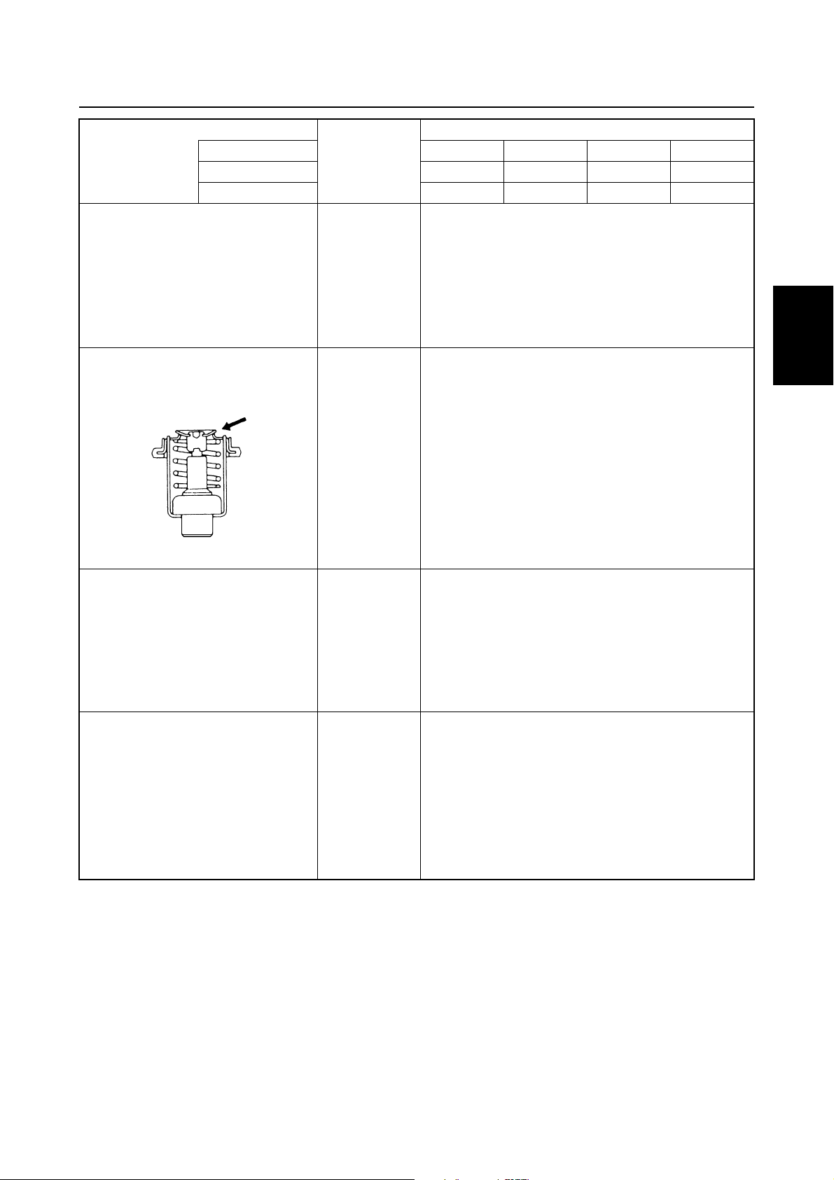
Thermostats
Opening temperature °C (°F) 60 (140)
Fully open temperature °C (°F) 70 (158)
USA ———F50TR
Canada — F50TH — F50TR
Worldwide F50AEHD F50AEHT F50AED F50AET
mm (in) 0.09–0.15 (0.004–0.006)
mm (in) 0.01–0.10 (0.0004–0.0039)
1
2
3
Valve open lower limit mm (in) 3.0 (0.12)
Fuel pump
Discharge L (US gal,
Imp gal)/hr
@ 6,000 r/min
Pressure kPa
(kgf/cm
Plunger stroke mm (in) 5.85–9.05 (0.23–0.35)
Carburetor
ID mark (USA and Canada) 62Y40
ID mark (worldwide) 62Y30
Main jet # #1: 124, #2: 126, #3: 116, #4: 114
Pilot jet # 39
Pilot screw turns out #1–#3: 2 1/4 ± 1/2, #4: 2 1/2 ± 1/2
Float height mm (in) 10.0 ± 0.5 (0.39 ± 0.02)
Engine idle speed r/min 750 ± 50 (950 ± 50)
2
, psi)
70 (18.5, 15.4)
49 (0.49, 7.0)
4
5
6
7
62Y3A11
2-8
8
I
Page 52
SPEC
Specifications
Lower unit
Model
Item Unit
Gear backlash
Pinion-to-forward gear mm (in) 0.18–0.54 (0.007–0.021)
Pinion-to-reverse gear mm (in) 0.71–1.07 (0.028–0.042)
Pinion shims mm 0.10, 0.12, 0.15, 0.18, 0.30, 0.40, 0.50
Forward gear shims mm 0.10, 0.12, 0.15, 0.18, 0.30, 0.40, 0.50
Reverse gear shims mm 0.10, 0.12, 0.15, 0.18, 0.30, 0.40, 0.50
Electrical
Item Unit
Ignition system
Ignition timing
(engine idle speed) Degree TDC ± 1.5
Charge coil output peak
voltage (L – Br)
@ cranking 1
@ cranking 2
@ 1,500 r/min V 169
@ 3,500 r/min V 129
Charge coil resistance
Pulser coil output peak voltage
@ cranking 1
@ cranking 2
@ 1,500 r/min V 7.4
@ 3,500 r/min V 11.2
Pulser coil resistance
CDI unit output peak voltage
(B/O – B, B/W – B)
@ cranking 1
@ cranking 2
@ 1,500 r/min V 151
@ 3,500 r/min V 116
Spark plug gap mm (in) 0.9 (0.035)
(*1)
Cranking 1: unloaded
Cranking 2: loaded
(*2)
The figures are for reference only.
USA ———F50TR
Canada — F50TH — F50TR
Worldwide F50AEHD F50AEHT F50AED F50AET
Model
USA ———F50TR
Canada — F50TH — F50TR
Worldwide F50AEHD F50AEHT F50AED F50AET
(*1)
V 144
(*1)
V 137
(*2)
Ω
272–408
(L – Br)
(W/R – W/B)
(*1)
V6.3
(*1)
V3.5
(*2)
Ω
396–594
(W/R – W/B)
(*1)
V 126
(*1)
V 150
2-9
62Y3A11
Page 53
Maintenance specifications
Model
Item Unit
Ignition control system
Oil pressure switch kPa
Thermoswitch (Gy/B – B)
Starter motor
Type Bendix
Output kW 1.1
Cranking time limit Second 30
Brushes
Standard length mm (in) 16.0 (0.63)
Wear limit mm (in) 12.0 (0.47)
Commutator
Standard diameter mm (in) 33.0 (1.30)
Wear limit mm (in) 31.0 (1.22)
Mica
Standard undercut mm (in) 0.8 (0.03)
Wear limit mm (in) 0.2 (0.01)
Charging system
Fuse A 20
Lighting coil output peak
voltage (G – G)
@ cranking
@ 1,500 r/min
@ 3,500 r/min
Lighting coil resistance
Rectifier Regulator output
peak voltage (R – B)
@ 1,500 r/min
@ 3,500 r/min
Charging current
Enrichment control system
Prime Start
(*1)
USA ———F50TR
Canada — F50TH — F50TR
Worldwide F50AEHD F50AEHT F50AED F50AET
50 (0.5, 7.11)
(kgf/cm
OFF → ON °C (°F) 76–84 (169–183)
ON → OFF °C (°F) 63–77 (145–170)
V 11.9
(*1)
V42
(*1)
V 127
(*2)
(G – G)
(*1)
V 18.9
(*1)
V 19.5
A @ 5,000 r/min
2
, psi)
Ω
1.2–1.8
1
2
3
4
5
6
10
7
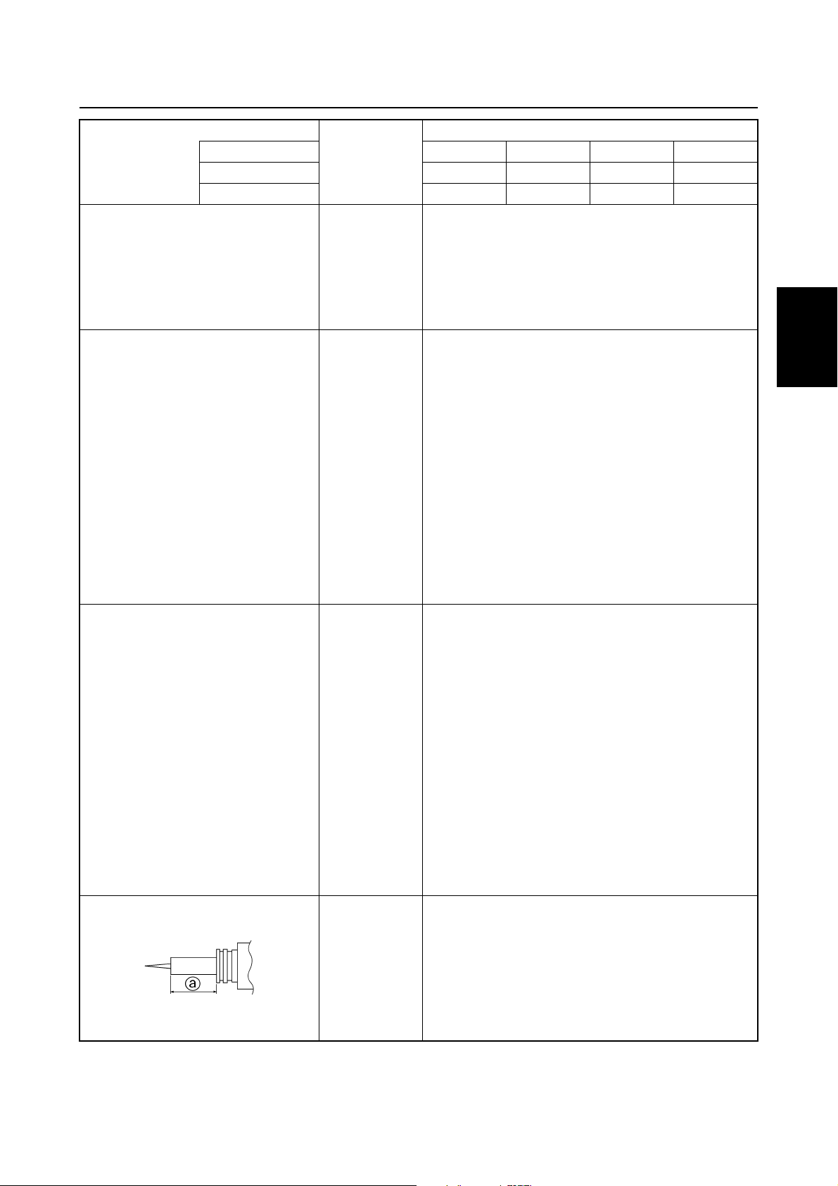
Plunger projection extended
minimum length a
(*1)
Unloaded
(*2)
The figures are for reference only.
62Y3A11
mm (in) 24.6 (0.97)
2-10
8
I
Page 54
SPEC
Specifications
Model
Item Unit
Power trim and tilt system
Trim sensor
Setting resistance
Resistance (P – B)
Fluid type ATF Dexron
Brushes
Standard length mm (in) 10 (0.39)
Wear limit mm (in) 3.5 (0.14)
Commutator
Standard diameter mm (in) 22.0 (0.87)
Wear limit mm (in) 21.0 (0.83)
Mica
Standard undercut mm (in) 1.5 (0.06)
USA ———F50TR
Canada — F50TH — F50TR
Worldwide F50AEHD F50AEHT F50AED F50AET
Ω
9
Ω
10–288.3
−
11
II
2-11
62Y3A11
Page 55
Maintenance specifications
Power unit
Model
Item Unit
Power unit
Minimum compression
pressure*
Lubrication oil pressure
at 55 °C (131 °F), with
10W-30 engine oil
Cylinder heads
Warpage limit mm (in) 0.1 (0.004)
USA T50TR ———
Canada T50TR ———
Worldwide FT50BET FT50CEHD FT50CED FT50CET
kPa
(kgf/cm
(kgf/cm
@ 900 r/min
2
kPa
2
, psi)
, psi)
840 (8.4, 119)
100 (1.0, 14)
1
2
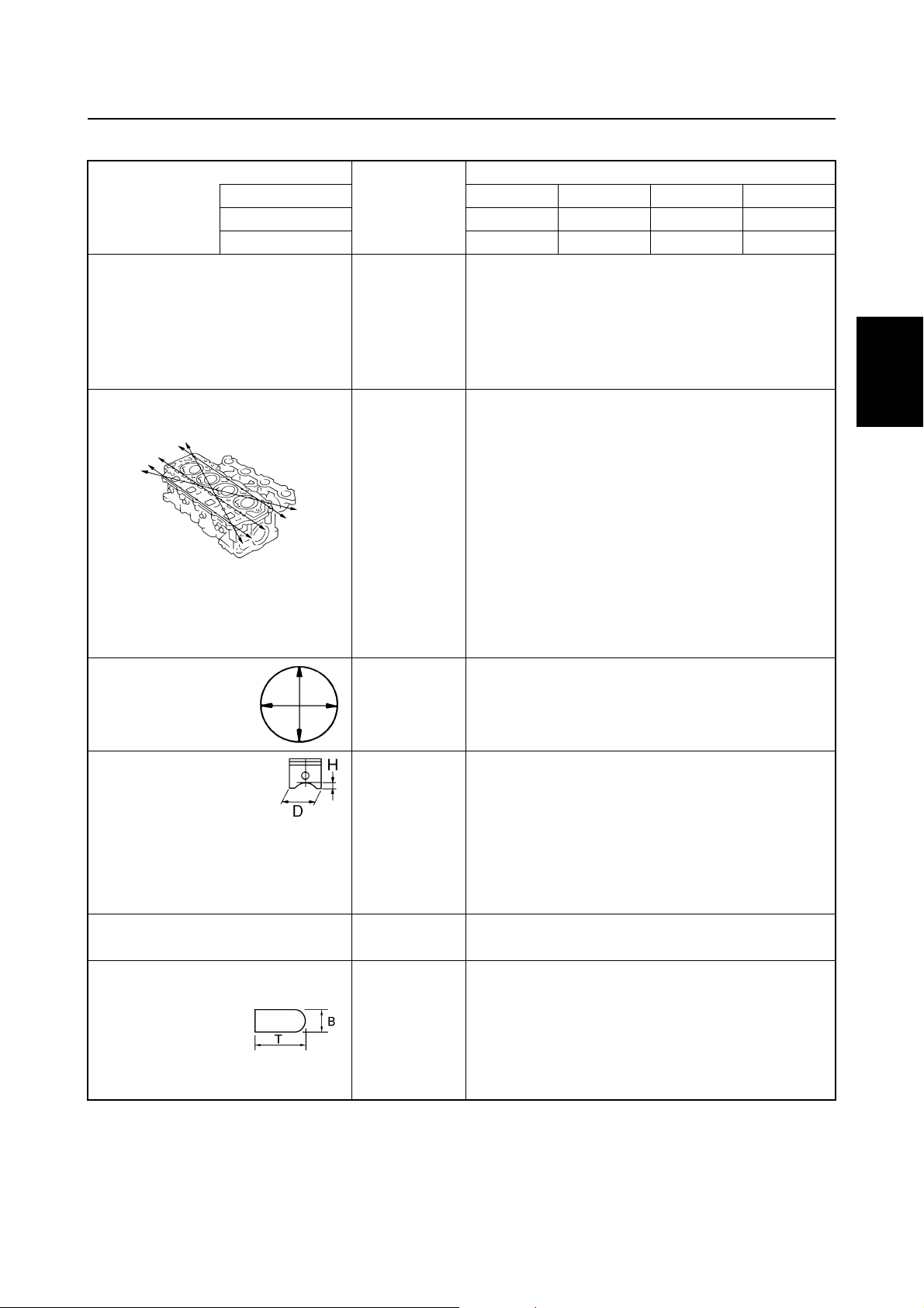
3
(lines indicate straightedge
position)
Cylinder head journal inside
diameter
Cylinders
Bore size mm (in) 63.00–63.01 (2.480–2.481)
Taper limit mm (in) 0.08 (0.003)
Out-of-round limit mm (in) 0.05 (0.002)
Pistons
Piston diameter (D) mm (in) 62.95–62.96 (2.478–2.479)
Measuring point (H) mm (in) 5 (0.2)
Piston-to-cylinder clearance mm (in) 0.04–0.06 (0.0016–0.0024)
Oversize piston diameter
1st mm (in) + 0.25 (0.01)
2nd mm (in) + 0.50 (0.02)
Piston pins
Outside diameter mm (in) 15.965–15.970 (0.6285–0.6287)
Piston rings
Top ring
Dimension B mm (in) 1.17–1.19 (0.046–0.047)
Dimension T mm (in) 2.39–2.41 (0.094–0.095)
End gap mm (in) 0.15–0.30 (0.006–0.012)
Side clearance mm (in) 0.04–0.08 (0.0016–0.003)
* Measuring conditions:
Ambient temperature 20 °C (68 °F), wide open throttle, with plugs disconnected from all cylinders.
The figures are for reference only.
mm (in) 37.00–37.02 (1.4567–1.4575)
4
5
6
7
8
62Y3A11
2-12
I
Page 56
SPEC
Specifications
Model
Item Unit
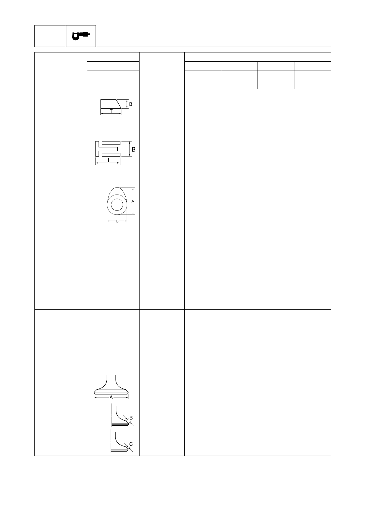
2nd ring
Dimension B mm (in) 1.47–1.49 (0.058–0.059)
Dimension T mm (in) 2.49–2.51 (0.098–0.099)
End gap mm (in) 0.30–0.50 (0.012–0.020)
Side clearance mm (in) 0.03–0.07 (0.001–0.003)
Oil ring
Dimension B mm (in) 2.34–2.46 (0.092–0.097)
Dimension T mm (in) 2.75 (0.108)
End gap mm (in) 0.20–0.70 (0.008–0.028)
Side clearance mm (in) 0.05–0.19 (0.002–0.008)
Camshafts
Intake (A) mm (in) 30.89–30.99 (1.2161–1.2200)
Exhaust (A) mm (in) 30.82–30.92 (1.2135–1.2175)
Intake and
exhaust (B)
Camshaft journal diameter
#1 mm (in) 36.93–36.94 (1.4539–1.4543)
#2, #3, #4 mm (in) 36.94–36.95 (1.4543–1.4547)
Camshaft journal oil clearance
#1 mm (in) 0.055–0.100 (0.0022–0.0039)
#2, #3, #4 mm (in) 0.045–0.090 (0.0018–0.0035)
Maximum camshaft runout mm (in) 0.04 (0.0016)
Rocker arm shafts
Outside diameter mm (in) 15.98–15.99 (0.6291–0.6295)
Rocker arms
Inside diameter mm (in) 16.00–16.01 (0.6299–0.6303)
Valves
Valve clearance (cold)
Intake mm (in) 0.20 ± 0.05 (0.008 ± 0.002)
Exhaust mm (in) 0.30 ± 0.05 (0.012 ± 0.002)
Head diameter (A)
Intake mm (in) 29.9–30.1 (1.177–1.185)
Exhaust mm (in) 25.9–26.1 (1.020–1.027)
USA T50TR ———
Canada T50TR ———
Worldwide FT50BET FT50CEHD FT50CED FT50CET
mm (in) 25.95–26.05 (1.0217–1.0256)
Face width (B)
Intake mm (in) 1.84–2.97 (0.072–0.117)
Exhaust mm (in) 1.98–3.11 (0.078–0.122)
Seat contact width (C)
Intake mm (in) 0.9–1.1 (0.035–0.043)
Exhaust mm (in) 0.9–1.1 (0.035–0.043)
2-13
62Y3A11
Page 57
Maintenance specifications
Model
Item Unit
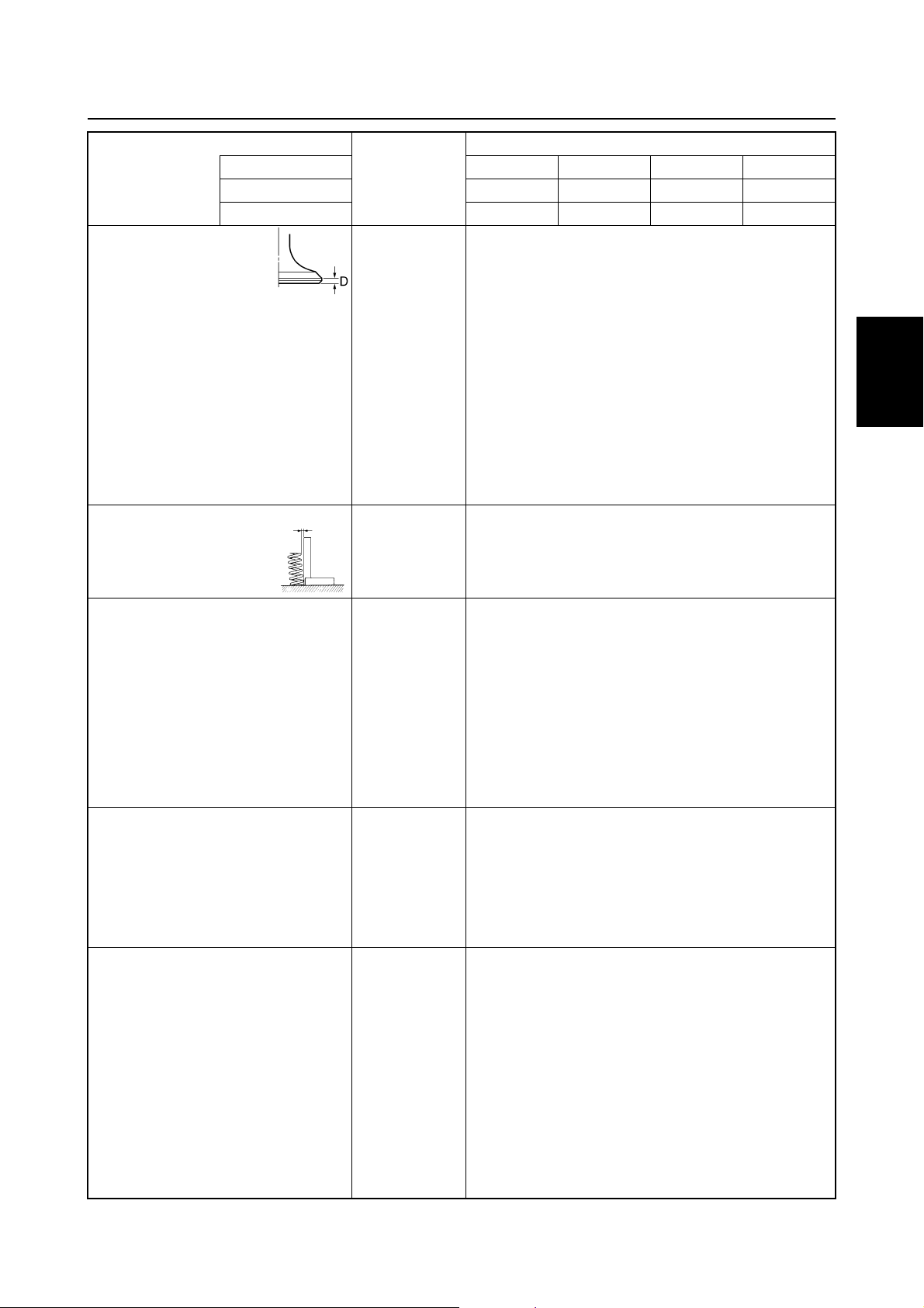
Margin thickness (D)
Intake mm (in) 0.6–1.0 (0.024–0.039)
Exhaust mm (in) 0.7–1.1 (0.028–0.043)
Stem diameter
Intake mm (in) 5.48–5.49 (0.2157–0.2161)
Exhaust mm (in) 5.46–5.47 (0.2150–0.2153)
Guide inside diameter
Intake and exhaust mm (in) 5.50–5.51 (0.2165–0.2169)
Stem-to-guide clearance
Intake mm (in) 0.01–0.03 (0.0004–0.0012)
Exhaust mm (in) 0.03–0.05 (0.0012–0.0020)
Stem runout limit mm (in) 0.03 (0.0012)
Valve springs
Free length mm (in) 39.85 (1.569)
Minimum free length mm (in) 37.85 (1.490)
Tilt limit mm (in) 1.7 (0.07)
Connecting rods
Small-end inside diameter mm (in) 15.985–15.998 (0.6293–0.6298)
Big-end inside diameter mm (in) 36.000–36.024 (1.4173–1.4183)
Crank pin oil clearance mm (in) 0.016–0.040 (0.0006–0.0015)
Big-end bearing thickness
Yellow mm (in) 1.500–1.504 (0.0591–0.0592)
Red mm (in) 1.496–1.500 (0.0589–0.0591)
Pink mm (in) 1.492–1.496 (0.0587–0.0589)
Green mm (in) 1.488–1.492 (0.0586–0.0587)
Crankshaft
Crankshaft journal
Diameter mm (in) 42.984–43.000 (1.6923–1.6929)
Crankshaft pin
Diameter mm (in) 32.984–33.000 (1.2986–1.2992)
Runout limit mm (in) 0.04 (0.0016)
Crankcase
Crankcase main journal inside
diameter
Crankshaft main journal oil
clearance
Crankcase main journal
bearing thickness
Yellow mm (in) 1.502–1.506 (0.0591–0.0593)
Red mm (in) 1.498–1.502 (0.0590–0.0591)
Pink mm (in) 1.494–1.498 (0.0588–0.0590)
Green mm (in) 1.490–1.494 (0.0587–0.0588)
USA T50TR ———
Canada T50TR ———
Worldwide FT50BET FT50CEHD FT50CED FT50CET
mm (in) 46.000–46.024 (1.8110–1.8120)
mm (in) 0.012–0.036 (0.0005–0.0014)
1
2
3
4
5
6
7
8
62Y3A11
2-14
I
Page 58
SPEC
Specifications
Model
Item Unit
Oil pump
Type Trochoid
Outer rotor-to-housing
clearance
Outer rotor-to-inner rotor
clearance limit
Rotor-to-cover clearance mm (in) 0.03–0.08 (0.001–0.003)
Thermostats
Opening temperature °C (°F) 60 (140)
Fully open temperature °C (°F) 70 (158)
USA T50TR ———
Canada T50TR ———
Worldwide FT50BET FT50CEHD FT50CED FT50CET
mm (in) 0.09–0.15 (0.004–0.006)
mm (in) 0.01–0.10 (0.0004–0.0039)
Valve open lower limit mm (in) 3.0 (0.12)
Fuel pump
Discharge L (US gal,
Imp gal)/hr
@ 6,000 r/min
Pressure kPa
(kgf/cm
Plunger stroke mm (in) 5.85–9.05 (0.23–0.35)
Carburetor
ID mark (USA and Canada) 62Y40 —
ID mark (worldwide) 62Y30 62Y30, 62Y50 (for Brazil)
Main jet # #1: 124, #2: 126, #3: 116, #4: 114
Pilot jet # 35, 39
Pilot screw turns out #1–#3: 2 1/4 ± 1/2, #4: 2 1/2 ± 1/2
Float height mm (in) 10.0 ± 0.5 (0.39 ± 0.02)
Engine idle speed r/min 750 ± 50 (950 ± 50)
2
, psi)
70 (18.5, 15.4)
49 (0.49, 7.0)
2-15
62Y3A11
Page 59
Maintenance specifications
Lower unit
Model
Item Unit
Gear backlash
Pinion-to-forward gear mm (in) 0.12–0.45 (0.005–0.018)
Pinion-to-reverse gear mm (in) 0.71–1.11 (0.028–0.044)
Pinion shims mm 0.10, 0.12, 0.15, 0.18, 0.30, 0.40, 0.50
Forward gear shims mm 0.10, 0.12, 0.15, 0.18, 0.30, 0.40, 0.50
USA T50TR ———
Canada T50TR ———
Worldwide FT50BET FT50CEHD FT50CED FT50CET
1
Electrical
Model
Item Unit
Ignition system
Ignition timing
(engine idle speed) Degree TDC ± 1.5
Charge coil output peak
voltage (L – Br)
@ cranking 1
@ cranking 2
@ 1,500 r/min V 169
@ 3,500 r/min V 129
Charge coil resistance
Pulser coil output peak voltage
@ cranking 1
@ cranking 2
@ 1,500 r/min V 7.4
@ 3,500 r/min V 11.2
Pulser coil resistance
CDI unit output peak voltage
(B/O – B, B/W – B)
@ cranking 1
@ cranking 2
@ 1,500 r/min V 151
@ 3,500 r/min V 116
Spark plug gap mm (in) 0.9 (0.035)
(*1)
Cranking 1: unloaded
Cranking 2: loaded
(*2)
The figures are for reference only.
USA T50TR ———
Canada T50TR ———
Worldwide FT50BET FT50CEHD FT50CED FT50CET
(*1)
V 144
(*1)
V 137
(*2)
(L – Br)
(W/R – W/B)
(*1)
V6.3
(*1)
V3.5
(*2)
(W/R – W/B)
(*1)
V 126
(*1)
V 150
Ω
272–408
Ω
396–594
2
3
4
5
6
7
8
62Y3A11
2-16
I
Page 60
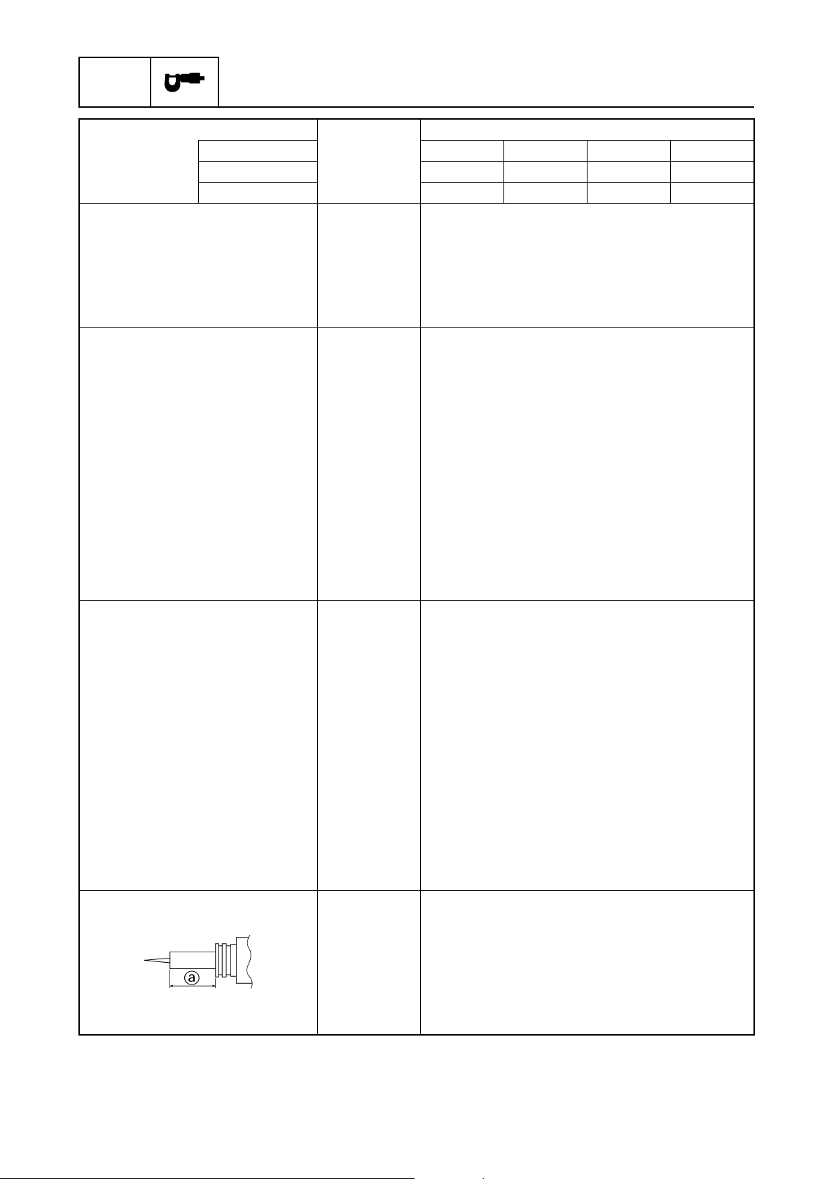
SPEC
Specifications
Model
Item Unit
Ignition control system
Oil pressure switch kPa
Thermoswitch (Gy/B – B)
Starter motor
Type Bendix
Output kW 1.1
Cranking time limit Second 30
Brushes
Standard length mm (in) 16.0 (0.63)
Wear limit mm (in) 12.0 (0.47)
Commutator
Standard diameter mm (in) 33.0 (1.30)
Wear limit mm (in) 31.0 (1.22)
Mica
Standard undercut mm (in) 0.8 (0.03)
Wear limit mm (in) 0.2 (0.01)
Charging system
Fuse A 20
Lighting coil output peak
voltage (G – G)
@ cranking
(*1)
@ 1,500 r/min
@ 3,500 r/min
Lighting coil resistance
Rectifier Regulator output
peak voltage (R – B)
@ 1,500 r/min
@ 3,500 r/min
Charging current
Enrichment control system
Prime Start
USA T50TR ———
Canada T50TR ———
Worldwide FT50BET FT50CEHD FT50CED FT50CET
50 (0.5, 7.11)
(kgf/cm
2
, psi)
OFF → ON °C (°F) 76–84 (169–183)
ON → OFF °C (°F) 63–77 (145–170)
V 11.9
(*1)
V42
(*1)
V 127
(*2)
Ω
1.2–1.8
(G – G)
(*1)
V 18.9
(*1)
V 19.5
A @ 5,000 r/min
10
Plunger projection extended
minimum length a
(*1)
Unloaded
(*2)
The figures are for reference only.
2-17
mm (in) 24.6 (0.97)
62Y3A11
Page 61
Maintenance specifications
Model
Item Unit
Power trim and tilt system
Trim sensor
Setting resistance
Resistance (P – B)
Fluid type ATF Dexron
Brushes
Standard length mm (in) 10 (0.39)
Wear limit mm (in) 3.5 (0.14)
Commutator
Standard diameter mm (in) 22.0 (0.87)
Wear limit mm (in) 21.0 (0.83)
Mica
Standard undercut mm (in) 1.5 (0.06)
USA T50TR ———
Canada T50TR ———
Worldwide FT50BET FT50CEHD FT50CED FT50CET
Ω
9
Ω
10–288.3
−
11
1
II
2
3
4
5
6
7
62Y3A11
2-18
8
I
Page 62
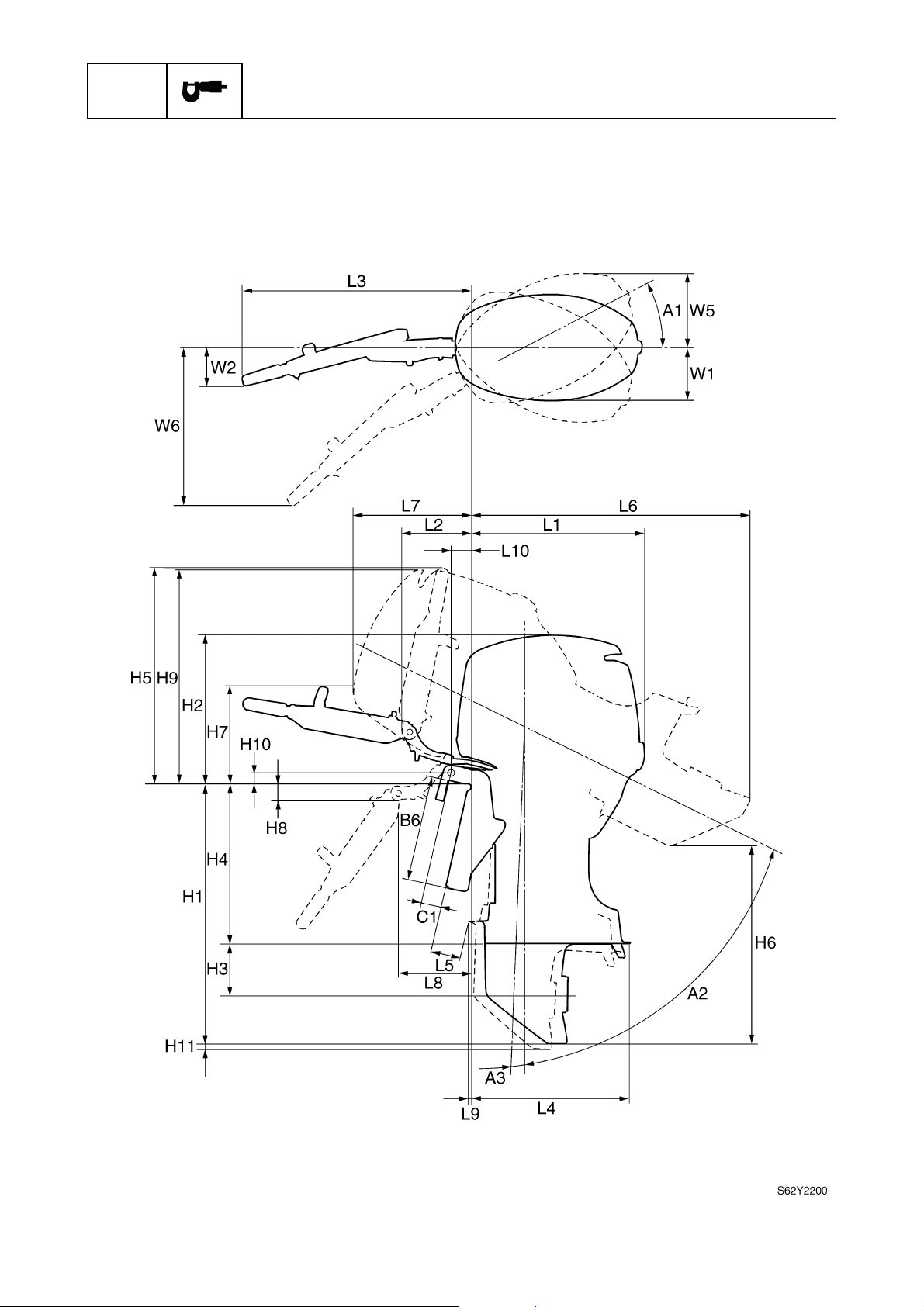
SPEC
Dimensions
Exterior
Specifications
2-19
62Y3A11
Page 63
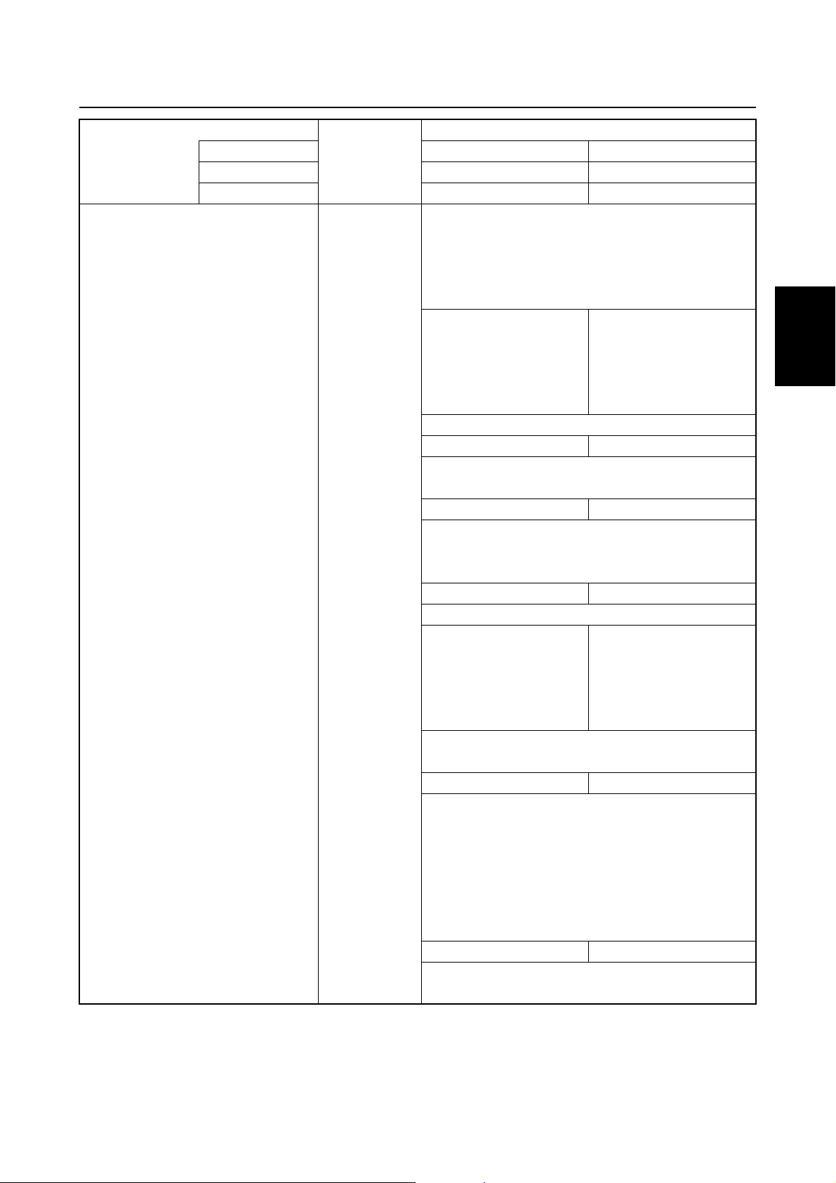
Maintenance specifications
Model
Symbol Unit
L1 mm (in) 576 (22.7)
L2 mm (in) 223 (8.8)
L3 mm (in) 753 (29.6)
L4 mm (in) 532 (20.9)
L5 (L) mm (in) 97 (3.8)
L6 (L) mm (in) 930 (36.6) 932 (36.7)
L7 mm (in) 397 (15.6) 407 (16.0)
L8 mm (in) 247 (9.7) 245 (9.6)
L9 (L) mm (in) 0.6 (0.02)
L10 mm (in) 63 (2.5)
H1 (L) mm (in) 876 (34.5)
H2 mm (in) 519 (20.4)
H3 mm (in) 175 (6.9)
H4 (L) mm (in) 536 (21.1)
H5 mm (in) 732 (28.8)
H6 (L) mm (in) 685 (27.0) 711 (28.0)
H7 mm (in) 330 (13.0) 327 (12.9)
H8 mm (in) 39 (1.5) 45 (1.8)
H9 mm (in) 738 (29.0) 733 (28.9)
H10 mm (in) 44 (1.7)
H11 (L) mm (in) 24 (0.9)
W1 mm (in) 181 (7.1)
W2 mm (in) 124 (4.9)
W3 mm (in) —
W4 mm (in) —
W5 mm (in) 345 (13.6)
W6 mm (in) 643 (25.3)
A1 Degree 40
A2 Degree 63 65
A3 Degree 4
T1 mm (in) —
USA ——
Canada — F50TH
Worldwide F50AEHD F50AEHT
(X) mm (in) — 85 (3.3)
(X) mm (in) — 1,036 (40.8)
(X) mm (in) — 16.8 (0.7)
(X) mm (in) — 990 (39.0)
(X) mm (in) — 647 (25.5)
(X) mm (in) — 776 (30.6)
(X) mm (in) — 24 (0.9)
1
2
3
4
5
6
7
8
62Y3A11
2-20
I
Page 64
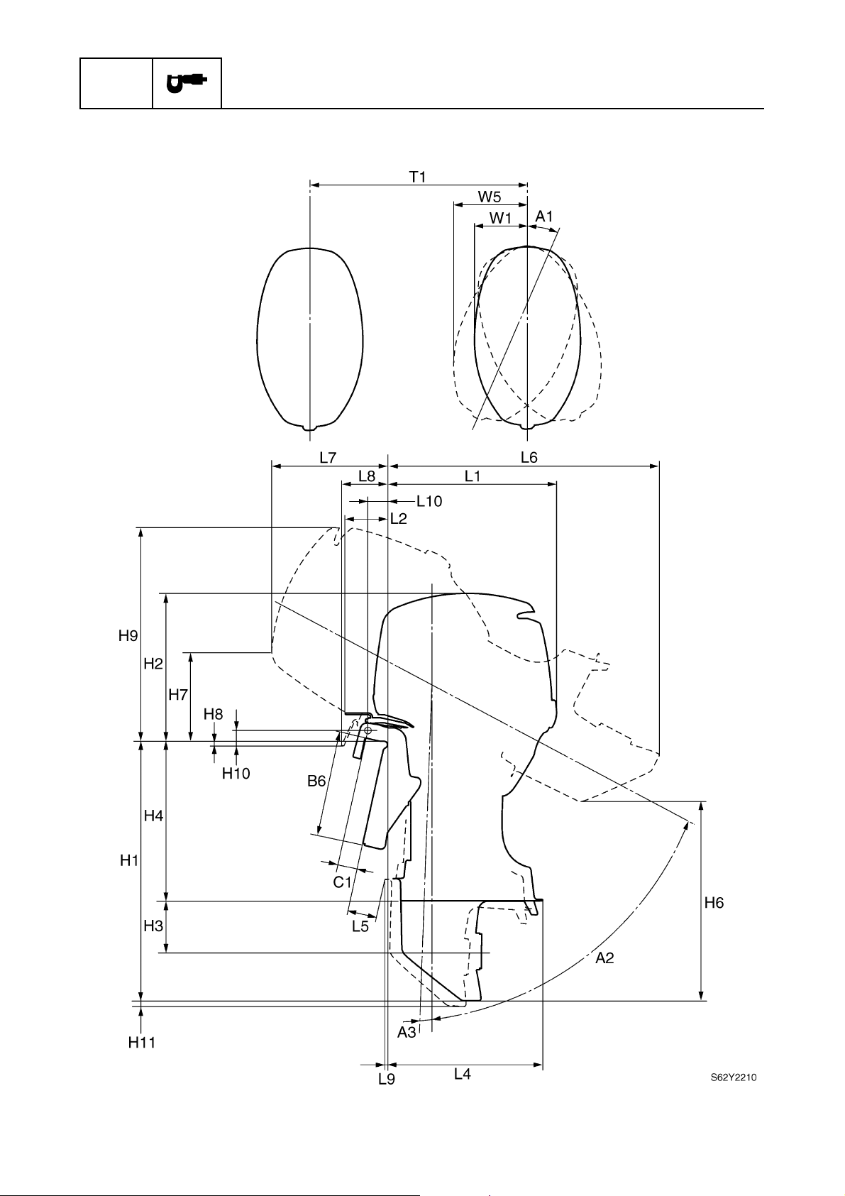
SPEC
Exterior
Specifications
2-21
62Y3A11
Page 65
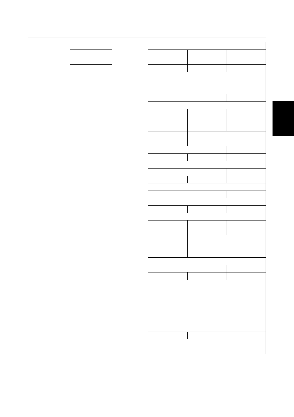
Maintenance specifications
Model
Symbol Unit
L1 mm (in) 576 (22.7)
L2 mm (in) 142 (5.6)
L3 mm (in) —
L4 mm (in) 532 (20.9) 560 (22.0)
L5 (L) mm (in) 97 (3.8)
L6 (L) mm (in) 930 (36.6) 932 (36.7) 990 (39.0)
L7 mm (in) 397 (15.6) 407 (16.0)
L8 mm (in) 149 (5.9) 148 (5.8)
L9 (L) mm (in) 0.6 (0.02) 0.8 (0.03)
L10 mm (in) 63 (2.5)
H1 (L) mm (in) 876 (34.5) 917 (36.1)
H2 mm (in) 519 (20.4)
H3 mm (in) 175 (6.9) 191 (7.5)
H4 (L) mm (in) 536 (21.1)
H5 mm (in) —
H6 (L) mm (in) 685 (27.0) 711 (28.0) 749 (29.5)
H7 mm (in) 330 (13.0) 327 (12.9)
H8 mm (in) 0.5 (0.02) 3.5 (0.1)
H9 mm (in) 738 (29.1) 733 (28.9)
H10 mm (in) 44 (1.7)
H11 (L) mm (in) 24 (0.9) 28 (1.1)
W1 mm (in) 181 (7.1)
W2 mm (in) —
W3 mm (in) —
W4 mm (in) —
W5 mm (in) 345 (13.6)
W6 mm (in) —
A1 Degree 40
A2 Degree 63 65
A3 Degree 4
T1 mm (in) 560 (22.0)
USA — F50TR T50TR
Canada — F50TR T50TR
Worldwide F50AED F50AET FT50BET
(X) mm (in) — 85 (3.3) —
(X) mm (in) — 1,036 (40.8) —
(X) mm (in) — 16.8 (0.7) —
(X) mm (in) — 990 (39.0) —
(X) mm (in) — 647 (25.5) —
(X) mm (in) — 776 (30.6) —
(X) mm (in) — 24 (0.9) —
1
2
3
4
5
6
7
8
62Y3A11
2-22
I
Page 66
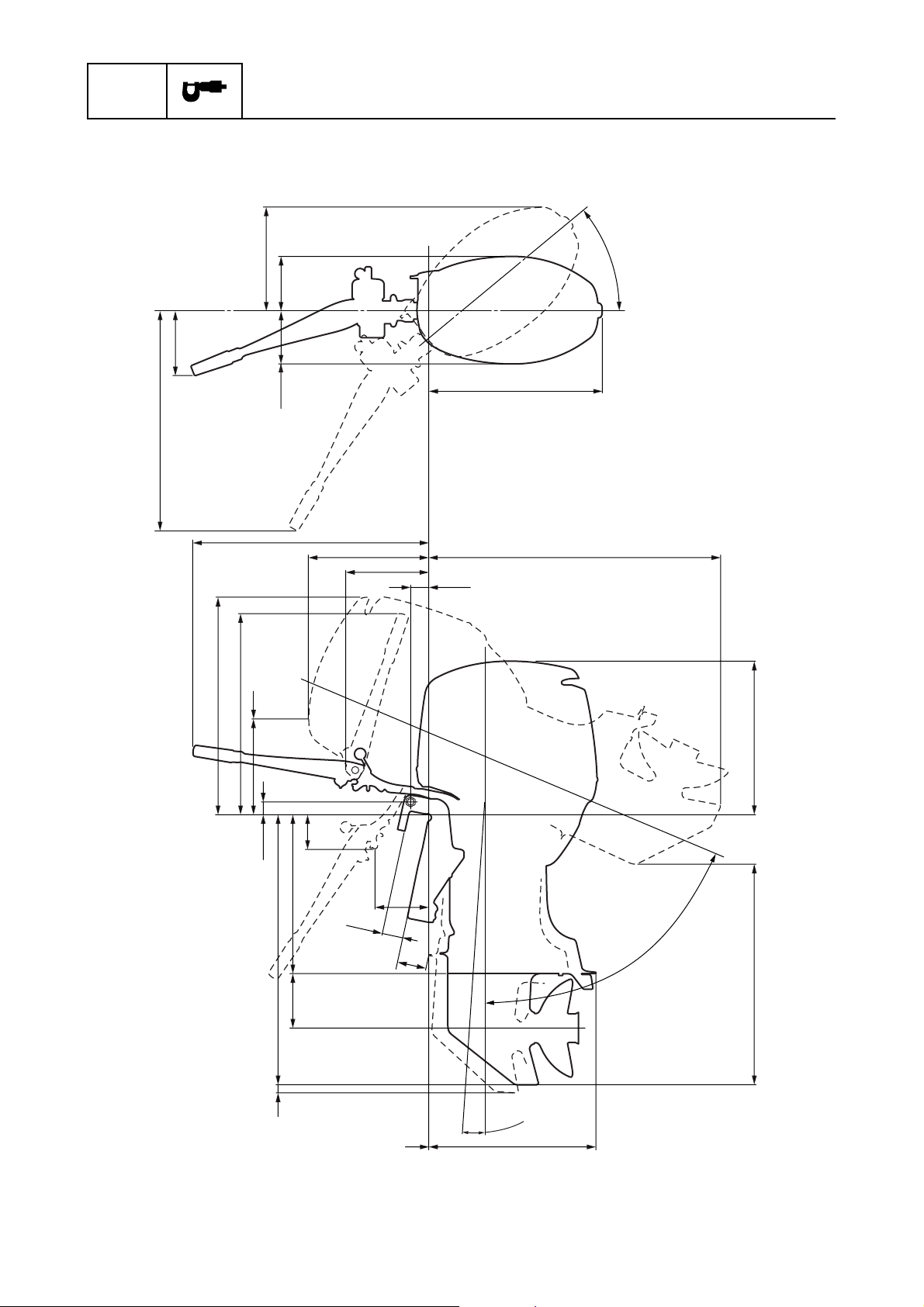
SPEC
Exterior
Specifications
W6
W2
H9
H5
W5
H7
W1
W3
L3
L7
A1
L1
L6
L2
L10
H1
H11
H10
H4
H3
H8
C1
L8
L5
L9
A3
L4
A2
H2
H6
S62Y2230
2-23
62Y3A11
Page 67
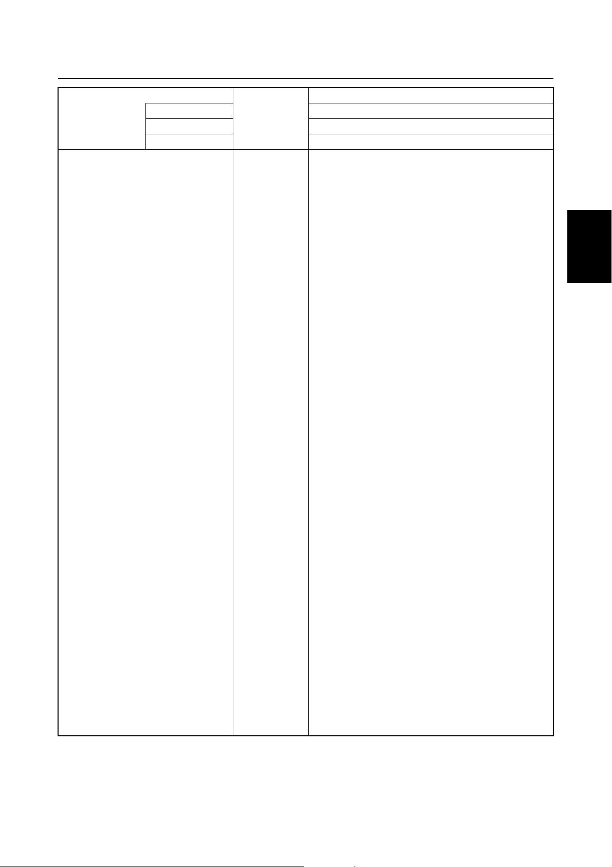
Maintenance specifications
Model
Symbol Unit
L1 mm (in) 576 (22.7)
L2 mm (in) 272 (10.7)
L3 mm (in) 797 (31.4)
L4 mm (in) 560 (22.0)
L5 (L) mm (in) 97 (3.8)
L6 (L) mm (in) 990 (39.0)
L7 mm (in) 397 (15.6)
L8 mm (in) 189 (7.4)
L9 (L) mm (in) 0.8 (0.03)
L10 mm (in) 63 (2.5)
H1 (L) mm (in) 917 (36.1)
H2 mm (in) 519 (20.4)
H3 mm (in) 191 (7.5)
H4 (L) mm (in) 536 (21.1)
H5 mm (in) 680 (26.8)
H6 (L) mm (in) 723 (28.5)
H7 mm (in) 330 (13.0)
H8 mm (in) 110 (4.3)
H9 mm (in) 738 (29.1)
H10 mm (in) 44 (1.7)
H11 (L) mm (in) 28 (1.1)
W1 mm (in) 181 (7.1)
W2 mm (in) 213 (8.4)
W3 mm (in) 181 (7.1)
W4 mm (in) —
W5 mm (in) 345 (13.6)
W6 mm (in) 738 (29.1)
A1 Degree 40
A2 Degree 63
A3 Degree 4
T1 mm (in) —
USA —
Canada —
Worldwide FT50CEHD
(X) mm (in) —
(X) mm (in) —
(X) mm (in) —
(X) mm (in) —
(X) mm (in) —
(X) mm (in) —
(X) mm (in) —
1
2
3
4
5
6
7
8
62Y3A11
2-24
I
Page 68
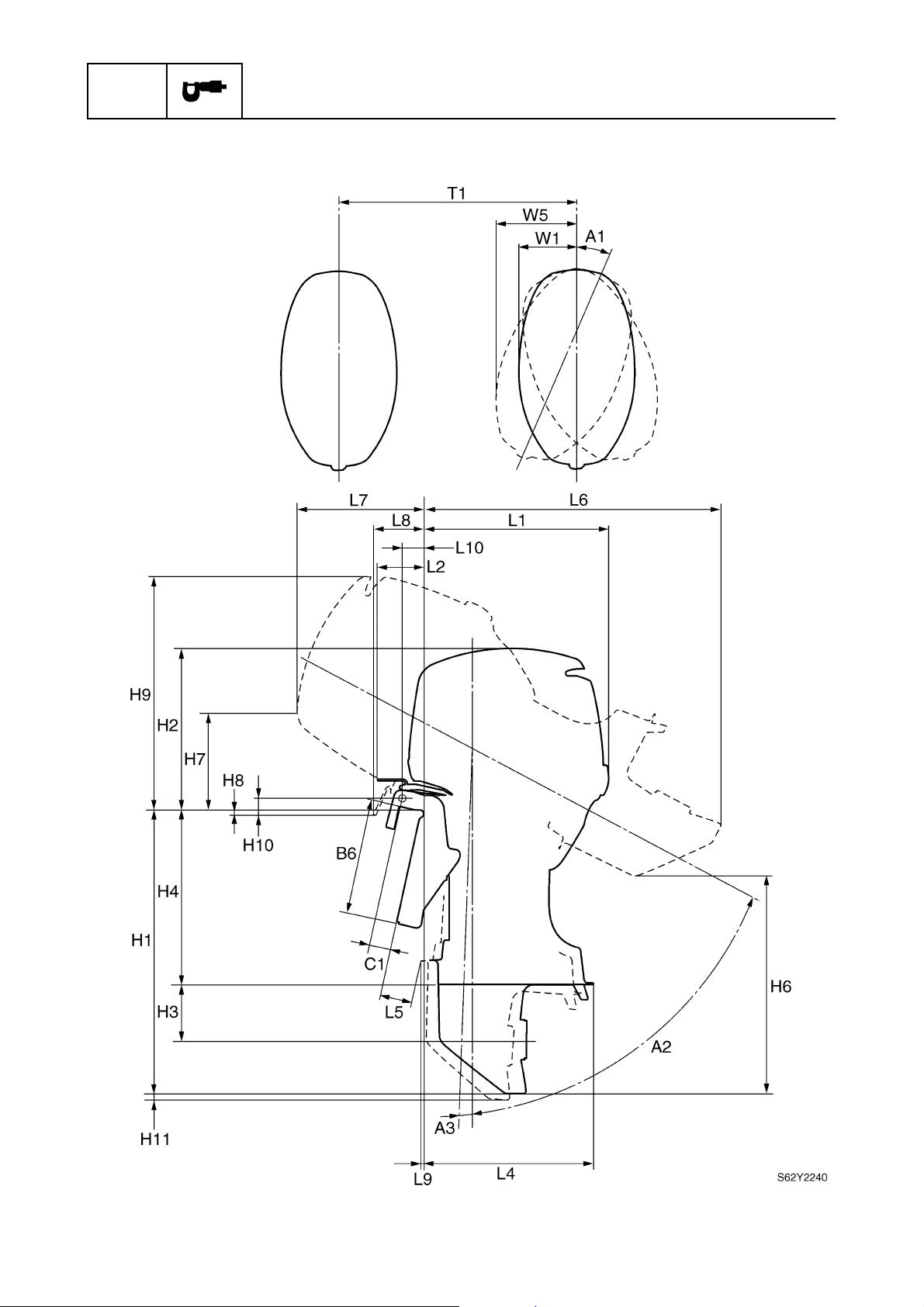
SPEC
Exterior
Specifications
2-25
62Y3A11
Page 69
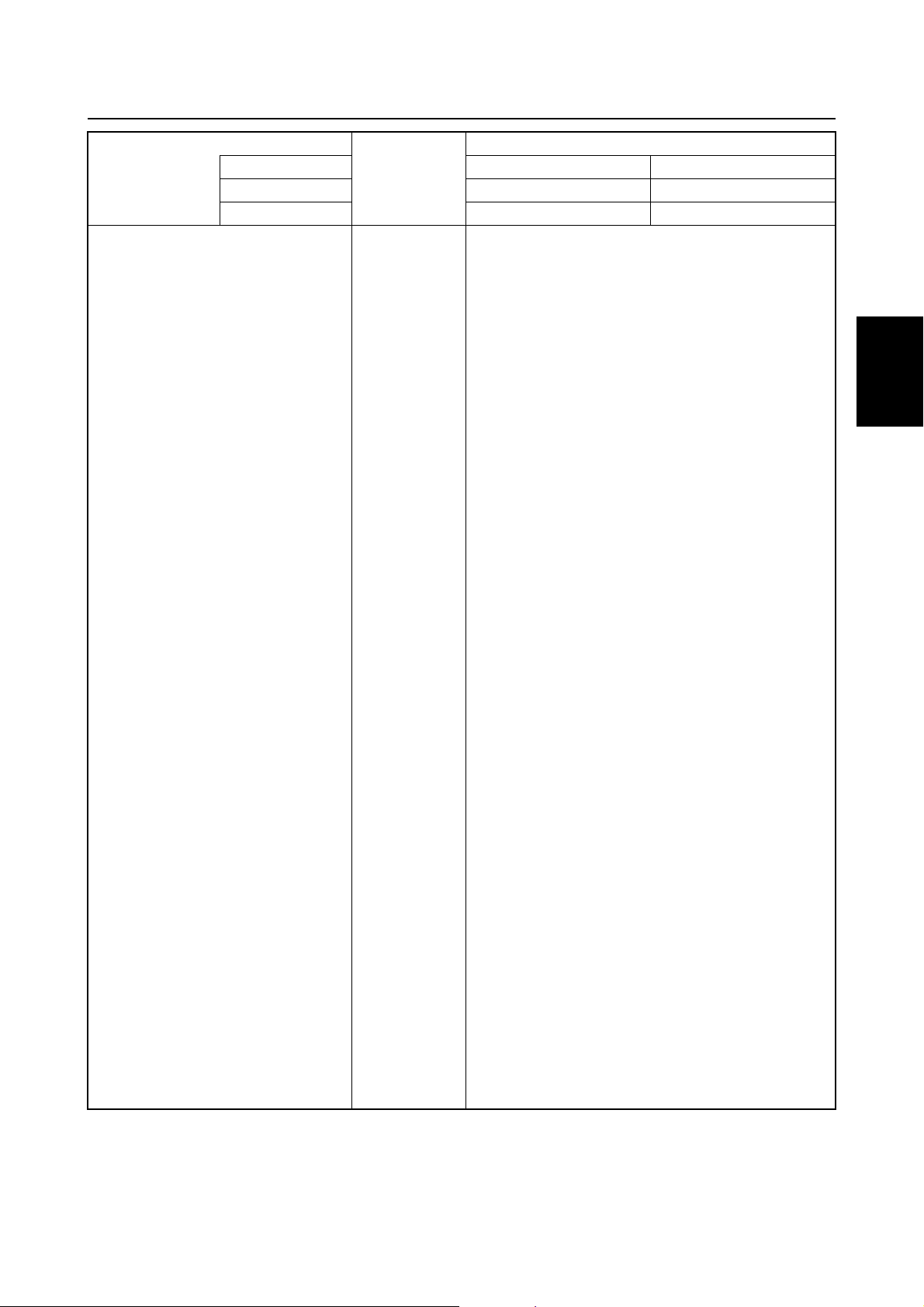
Maintenance specifications
Model
Symbol Unit
L1 mm (in) 576 (22.7)
L2 mm (in) 142 (5.6)
L3 mm (in) —
L4 mm (in) 560 (22.0)
L5 (L) mm (in) 97 (3.8)
L6 (L) mm (in) 990 (39.0)
L7 mm (in) 397 (15.6)
L8 mm (in) 149 (5.9)
L9 (L) mm (in) 0.8 (0.03)
L10 mm (in) 63 (2.5)
H1 (L) mm (in) 917 (36.1)
H2 mm (in) 519 (20.4)
H3 mm (in) 191 (7.5)
H4 (L) mm (in) 536 (21.1)
H5 mm (in) —
H6 (L) mm (in) 723 (28.5)
H7 mm (in) 330 (13.0)
H8 mm (in) 0.5 (0.02)
H9 mm (in) 738 (29.1)
H10 mm (in) 44 (1.7)
H11 (L) mm (in) 28 (1.1)
W1 mm (in) 181 (7.1)
W2 mm (in) —
W3 mm (in) 181 (7.1)
W4 mm (in) —
W5 mm (in) 345 (13.6)
W6 mm (in) —
A1 Degree 40
A2 Degree 63
A3 Degree 4
T1 mm (in) 560 (22.0)
USA ——
Canada ——
Worldwide FT50CED FT50CET
(X) mm (in) —
(X) mm (in) —
(X) mm (in) —
(X) mm (in) —
(X) mm (in) —
(X) mm (in) —
(X) mm (in) —
1
2
3
4
5
6
7
8
62Y3A11
2-26
I
Page 70
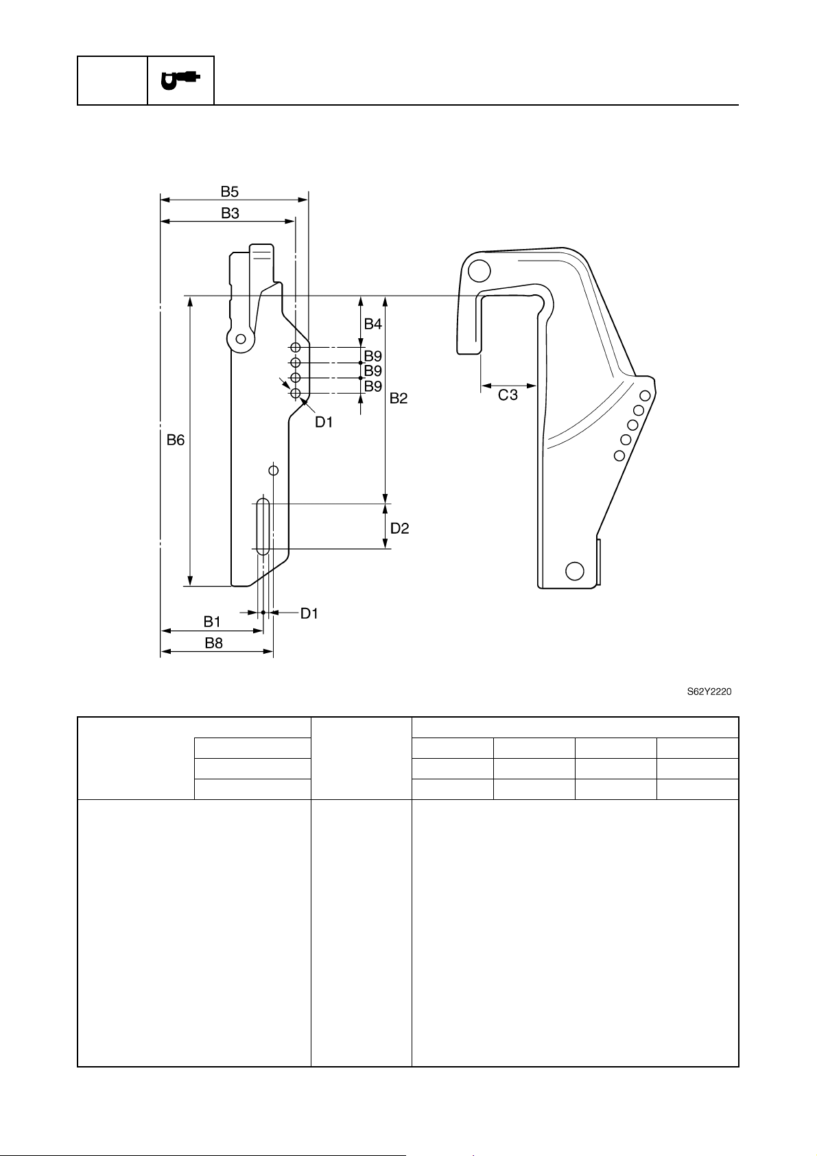
SPEC
Clamp bracket
Specifications
Model
Symbol Unit
B1 mm (in) 126 (5.0)
B2 mm (in) 254 (10.0)
B3 mm (in) 163.5 (6.4)
B4 mm (in) 50.8 (2.0)
B5 mm (in) 180 (7.1)
B6 mm (in) 355 (14.0)
B7 mm (in) —
B8 mm (in) 139 (5.5)
B9 mm (in) 18.5 (0.7)
C2 mm (in) —
C3 mm (in) 69 (2.7)
D1 mm (in) 13 (0.5)
D2 mm (in) 55.5 (2.2)
USA ———F50TR
Canada — F50TH — F50TR
Worldwide F50AEHD F50AEHT F50AED F50AET
2-27
62Y3A11
Page 71
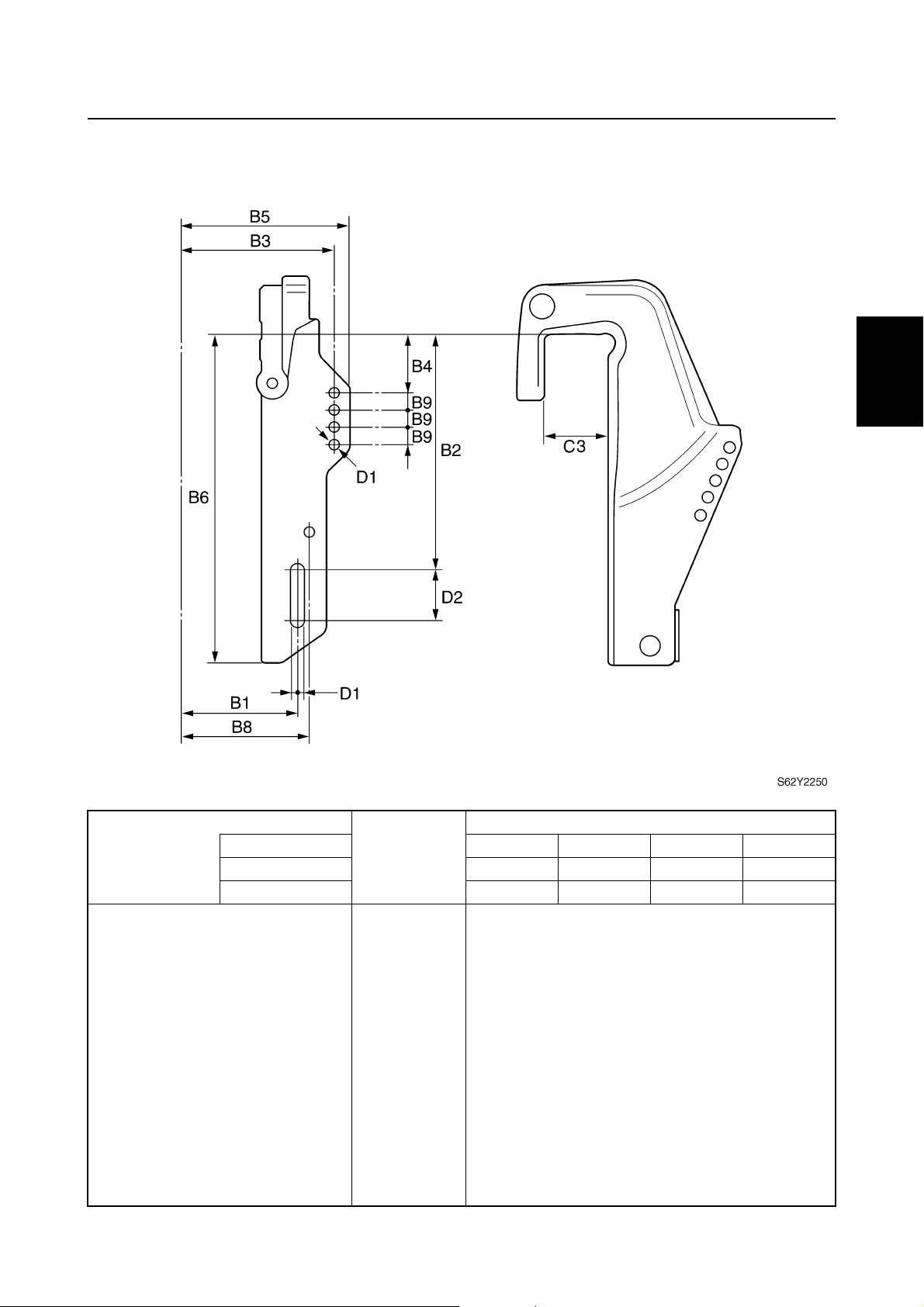
Clamp bracket
Maintenance specifications
1
2
3
Model
Symbol Unit
B1 mm (in) 126 (5.0)
B2 mm (in) 254 (10.0)
B3 mm (in) 163.5 (6.4)
B4 mm (in) 50.8 (2.0)
B5 mm (in) 180 (7.1)
B6 mm (in) 355 (14.0)
B7 mm (in) —
B8 mm (in) 139 (5.5)
B9 mm (in) 18.5 (0.7)
C2 mm (in) —
C3 mm (in) 69 (2.7)
D1 mm (in) 13 (0.5)
D2 mm (in) 55.5 (2.2)
USA T50TR ———
Canada T50TR ———
Worldwide FT50BET FT50CEHD FT50CED FT50CET
4
5
6
7
8
62Y3A11
2-28
I
Page 72
SPEC
Specifications
Tightening torques
2
Specified torques
Part to be tightened Thread size
Power unit
Flywheel magnet nut — 160 16 116
Stator base screw M6 4 0.4 2.9
Cover screw M6 3 0.3 2.2
Negative battery lead bolt M8 9 0.9 6.5
Positive battery lead nut — 70.75.1
Oil pressure switch — 90.96.5
Oil pressure switch lead screw — 20.21.4
Ignition coil bolt M6 7 0.7 5.1
Starter motor bolt M8 30 3.0 22
Starter motor terminal nut — 70.75.1
Power unit bolt M8 21 2.1 15
Tensioner bolt — 80.85.8
Tensioner adjusting bolt M8 25 2.5 18
Drive sprocket nut — 140 14 101
Driven sprocket bolt M10 38 3.8 28
Spark plug — 18 1.8 13
1st
Cylinder head bolt
Adjusting screw locknut — 14 1.4 10
Oil filter — 18 1.8 13
Drain bolt — 18 1.8 13
Exhaust cover bolt
Crankcase bolt
Connecting rod cap bolt
Lower unit (F50/F50A)
Check screw — 70.75.1
Lower unit bolt M10 40 4.0 29
Drain screw — 70.75.1
Propeller nut — 35 3.5 25
Water inlet cover screw — 50.53.6
Pinion nut M17 75 7.5 54
2nd 12 1.2 8.7
1st
2nd 47 4.7 34
1st
2nd 12 1.2 8.7
1st
2nd 12 1.2 8.7
1st
2nd 30 3.0 22
1st
2nd 17 1.7 12
M6
M9
M6
M6
M8
—
Tightening torques
N·mkgf·mft·lb
60.64.3
23 2.3 17
60.64.3
60.64.3
15 1.5 11
60.64.3
2-29
62Y3A11
Page 73
Tightening torques
Part to be tightened Thread size
Lower unit (T50/FT50B, FT50C)
Check screw — 70.75.1
Lower unit bolt M10 40 4.0 29
Drain screw — 70.75.1
Propeller nut — 35 3.5 25
Ring nut — 105 10.5 76
Water inlet cover screw — 50.53.6
Pinion nut M22 95 9.5 69
Bracket unit
Tiller handle assembly nut (F50/F50A) — 37 3.7 27
Engine shut-off switch nut (F50/F50A) — 40.42.9
Tiller handle bracket nut (F50/F50A) — 38 3.8 27
Main switch nut (F50/F50A) — 50.53.7
Friction wing nut (FT50C) — 13 1.3 9.4
Tiller handle assembly nut (FT50C) — 37 3.7 27
Throttle cable (short) locknut (FT50C) — 37 3.7 27
Upper mount nut — 24 2.4 17
Lower mount nut — 42 4.2 30
Trim sensor screw M6 2 0.2 1.4
Clamp bracket self-locking nut — 23 2.3 17
Power trim and tilt
Tilt cylinder end screw — 90 9.0 65
PTT motor bolt M5 4 0.4 2.9
Reservoir cap — 6.5 0.65 4.7
Trim cylinder end screw — 80 8.0 58
Tilt piston bolt M12 61 6.1 44
Relief valve bracket bolt M5 5.3 0.53 3.8
Gear pump assembly bolt M6 6.5 0.65 4.7
Gear pump bracket bolt M5 5.3 0.53 3.8
Electrical unit
Pulser coil screw — 40.42.9
Starter motor nut — 90.96.5
Tightening torques
N·mkgf·mft·lb
1
2
3
4
5
6
62Y3A11
2-30
7
8
I
Page 74
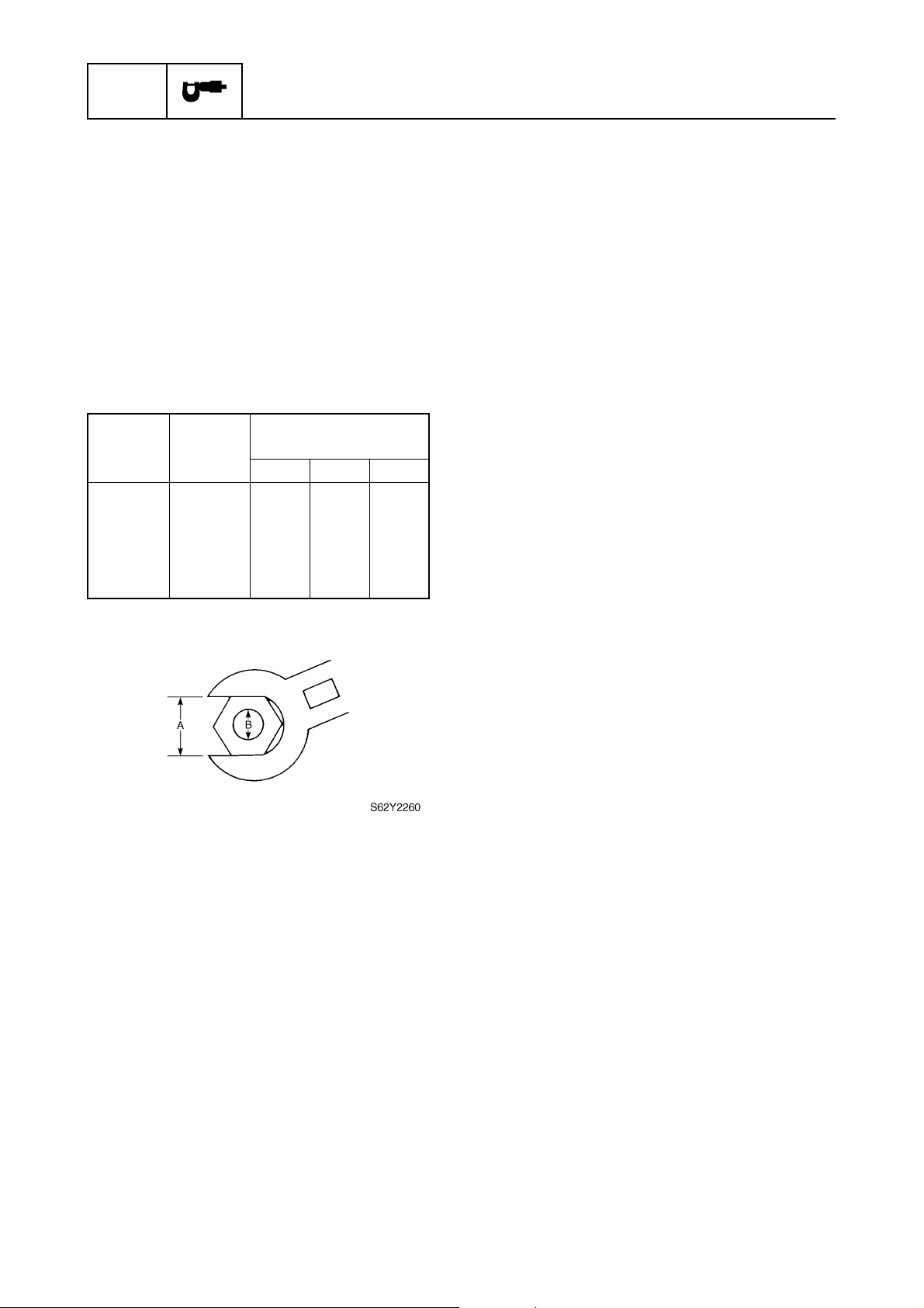
SPEC
Specifications
General torques
This chart specifies tightening torques for
standard fasteners with a standard ISO
thread pitch. Tightening torque specifications
for special components or assemblies are
provided in applicable sections of this manual. To avoid warpage, tighten multi-fastener
assemblies in a crisscross fashion and progressive stages until the specified torque is
reached. Unless otherwise specified, torque
specifications require clean, dry threads.
Components should be at room temperature.
General torque
Nut (A) Bolt (B)
8 mm M5 5 0.5 3.6
10 mm M6 8 0.8 5.8
12 mm M8 18 1.8 13
14 mm M10 36 3.6 25
17 mm M12 43 4.3 31
specifications
N·mkgf·mft·lb
2-31
62Y3A11
Page 75
CHK
ADJ
Periodic checks and adjustments
Special service tools .....................................................................................3-1
Maintenance interval chart............................................................................3-3
Top cowling ....................................................................................................3-4
Checking the top cowling...........................................................................3-4
Fuel system ....................................................................................................3-4
Checking the fuel joint and fuel hoses (fuel joint-to-carburetor) ................3-4
Checking the fuel filter ...............................................................................3-5
Power unit.......................................................................................................3-5
Checking the engine oil .............................................................................3-5
Replacing the engine oil ............................................................................3-5
Checking the timing belt ............................................................................3-7
Replacing the timing belt ...........................................................................3-7
Checking the valve clearance..................................................................3-10
Checking the spark plugs ........................................................................3-11
Checking the thermostat..........................................................................3-12
Checking the cooling water passage.......................................................3-13
Control system.............................................................................................3-13
Checking the throttle cable operation......................................................3-13
Checking the gearshift operation.............................................................3-14
Checking the engine idle speed ..............................................................3-15
Checking the ignition timing.....................................................................3-15
1
2
3
4
5
62Y3A11
Power trim and tilt unit ................................................................................3-16
Checking the power trim and tilt operation ..............................................3-16
Checking the power trim and tilt fluid level ..............................................3-16
Lower unit.....................................................................................................3-17
Checking the gear oil level ......................................................................3-17
Replacing the gear oil..............................................................................3-17
Checking the lower unit (for air leakage).................................................3-19
Checking the propeller.............................................................................3-19
General..........................................................................................................3-19
Checking the anodes...............................................................................3-19
Checking the battery................................................................................3-20
Lubrication ...............................................................................................3-21
6
7
8
I
Page 76
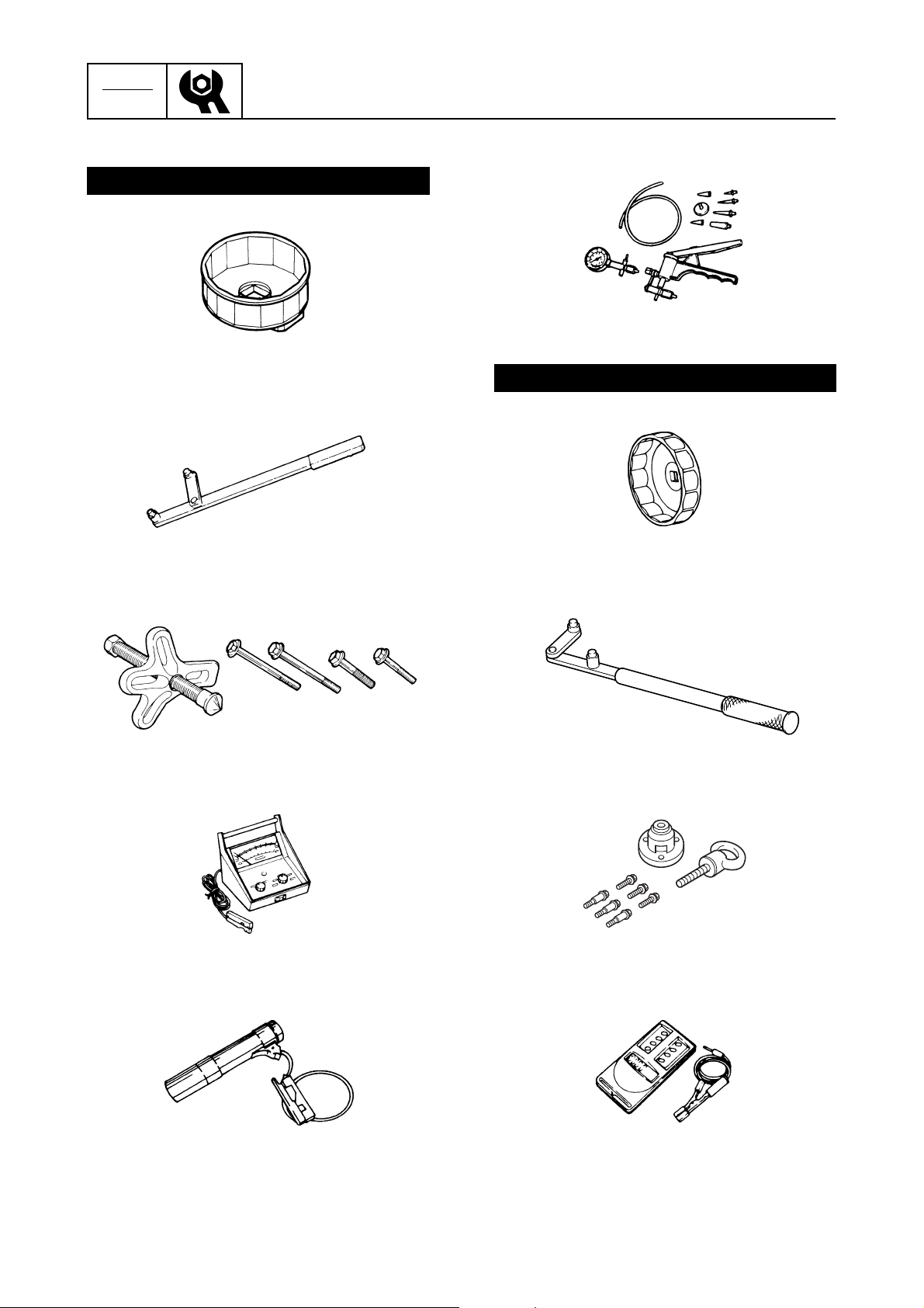
CHK
ADJ
Periodic checks and adjustments
Special service tools
For USA and Canada
Oil filter wrench
YU-38411
Flywheel magnet holder
YB-06139
3
Pressurfge/vacuum tester
YB-35956-A
For worldwide
Oil filter wrench
90890-01426
Universal puller
YB-06117
Inductive self-powered tachometer
YU-08036-B
Battery powered timing light
YM-33277-A
Flywheel holder
90890-06522
Flywheel puller
90890-06521
Digital tachometer
90890-06760
3-1
62Y3A11
Page 77
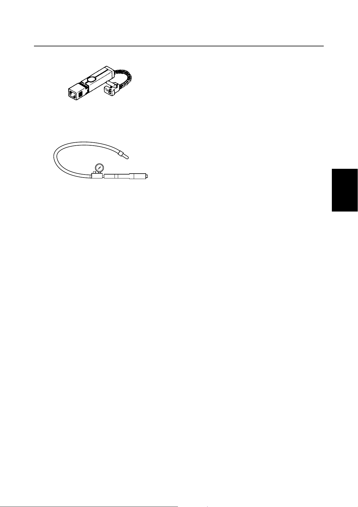
Special service tools
Timing light
90890-03141
Leakage tester
90890-06762
1
2
3
4
5
6
7
8
62Y3A11
3-2
I
Page 78
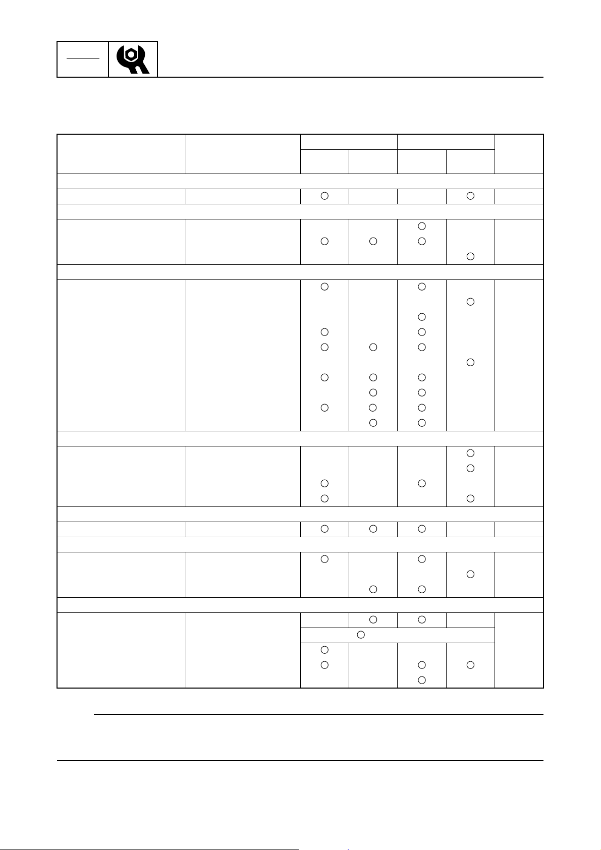
CHK
ADJ
Periodic checks and adjustments
Maintenance interval chart
Use the following chart as a guideline for general maintenance.
Adjust the maintenance intervals according to the operating conditions of the outboard.
Initial Every
Item Remarks
10 hours
(Break-in)
50 hours
(3 months)
100 hours
(6 months)
200 hours
(1 year)
Top cowling
Top cowling fit Check 3-4
Fuel system
Fuel joint and fuel hoses Check 3-4
Fuel filter Check/replace 3-5
Fuel tank Cleaning —
Power unit
Engine oil Change 3-5
Oil filter Change 3-5
Timing belt Check 3-7
Valve clearance Check/adjust 3-10
Spark plugs Clean/adjust/replace 3-11
Thermostat Check 3-12
Water leakage Check —
Motor exterior Check —
Exhaust leakage Check —
Cooling water passage Clean 3-13
Control system
Throttle cable Check/adjust 3-13
Shift cable Check/adjust 3-14
Engine idle speed Adjust 3-15
Ignition timing Check 3-15
Power trim and tilt unit
Power trim and tilt Check 3-16
Lower unit
Gear oil Change 3-17
Lower unit leakage Check 3-19
Propeller Check 3-19
General
Anodes Check/replace 3-19
Battery Check every 1 month 3-20
Wiring and connectors Check/reconnect —
Nuts and bolts Tighten —
Lubrication points Lubricate 3-21
Refer to
page
3
NOTE:
• If operating in salt water, turbid or muddy water, flush the engine with fresh water after each use.
• If leaded gasoline is used regularly, check the engine valves and related parts every 300 hours of
operation in addition to the items in the maintenance interval chart.
3-3
62Y3A11
Page 79
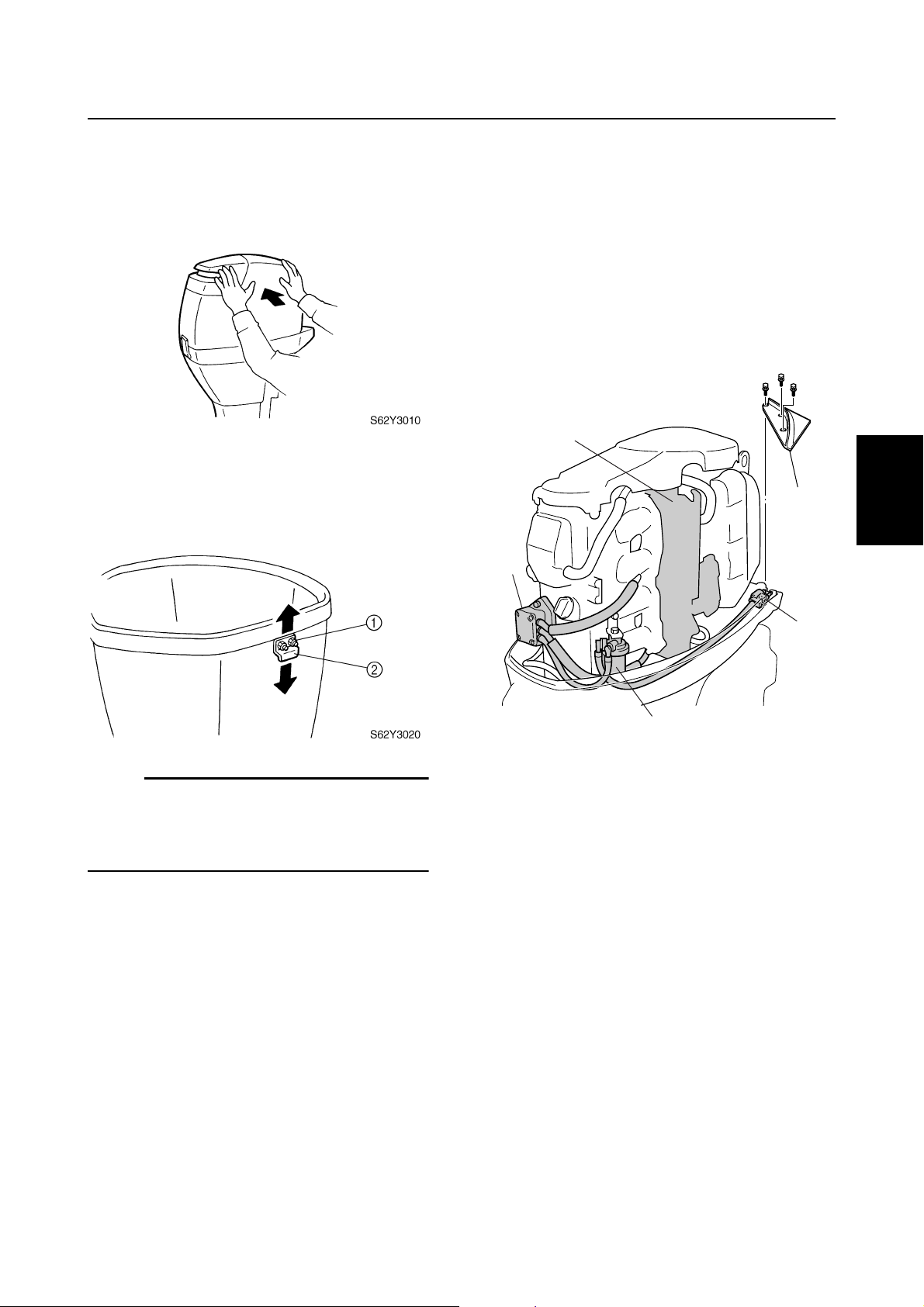
Maintenance interval chart / Top cowling / Fuel system
Top cowling
Checking the top cowling
1. Check the fitting by pushing the cowling
with both hands. Adjust if necessary.
2. Loosen the nuts and bolts 1.
3. Move the hook 2 up or down slightly to
adjust its position.
3
Fuel system
Checking the fuel joint and fuel
hoses (fuel joint-to-carburetor)
1. Remove the plate 1, and then check the
fuel hose connections and fuel joint 2 for
leaks. Replace if necessary. Also, check
the fuel filter 3, fuel pump 4, and carburetor 5 for leaks, and the fuel hoses for
leaks and deterioration. Replace if necessary.
3
1
2
5
1
3
4
NOTE:
• To loosen the fitting, move the hook toward
the seal.
• To tighten the fitting, move the hook away
from the seal.
4. Tighten the nuts and bolts.
5. Check the fitting again and, if necessary,
repeat steps 2–4.
3
2
S62Y3030
4
5
6
7
62Y3A11
3-4
8
I
Page 80
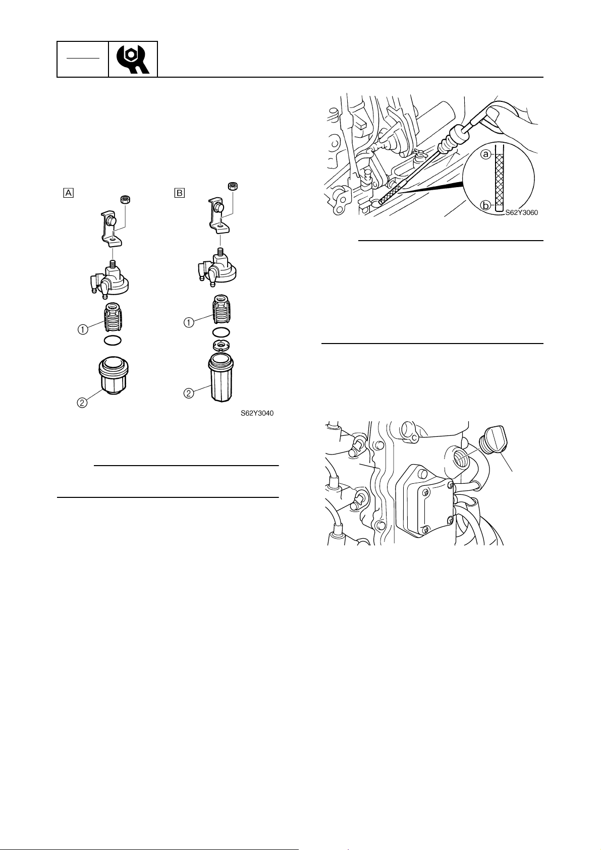
CHK
ADJ
Checking the fuel filter
1. Check the fuel filter element 1 for dirt
and residue and check the fuel filter cup
2
for foreign substances and cracks.
Clean with straight gasoline and replace
the cup if necessary.
Periodic checks and adjustments
NOTE:
• Replace the oil if it appears milky or black.
• If the engine oil is above the maximum level
mark a, drain sufficient oil until the level is
between a and b.
• If the engine oil is below the minimum level
mark b, add sufficient oil until the level is
between a and b.
F50/F50A
È
T50/FT50B, FT50C
É
NOTE:
Be sure not to spill any fuel when removing
the fuel filter cup.
Power unit
Checking the engine oil
1. Place the outboard in an upright position.
2. Remove the engine oil dipstick, wipe it
clean, and then insert it back into the oil
filler hole.
3. Remove the dipstick again to check the
oil level and the oil for discoloration, and
its viscosity.
Replacing the engine oil
1. Remove the engine oil dipstick and oil
filler cap 1.
1
3
S62Y3070
3-5
62Y3A11
Page 81
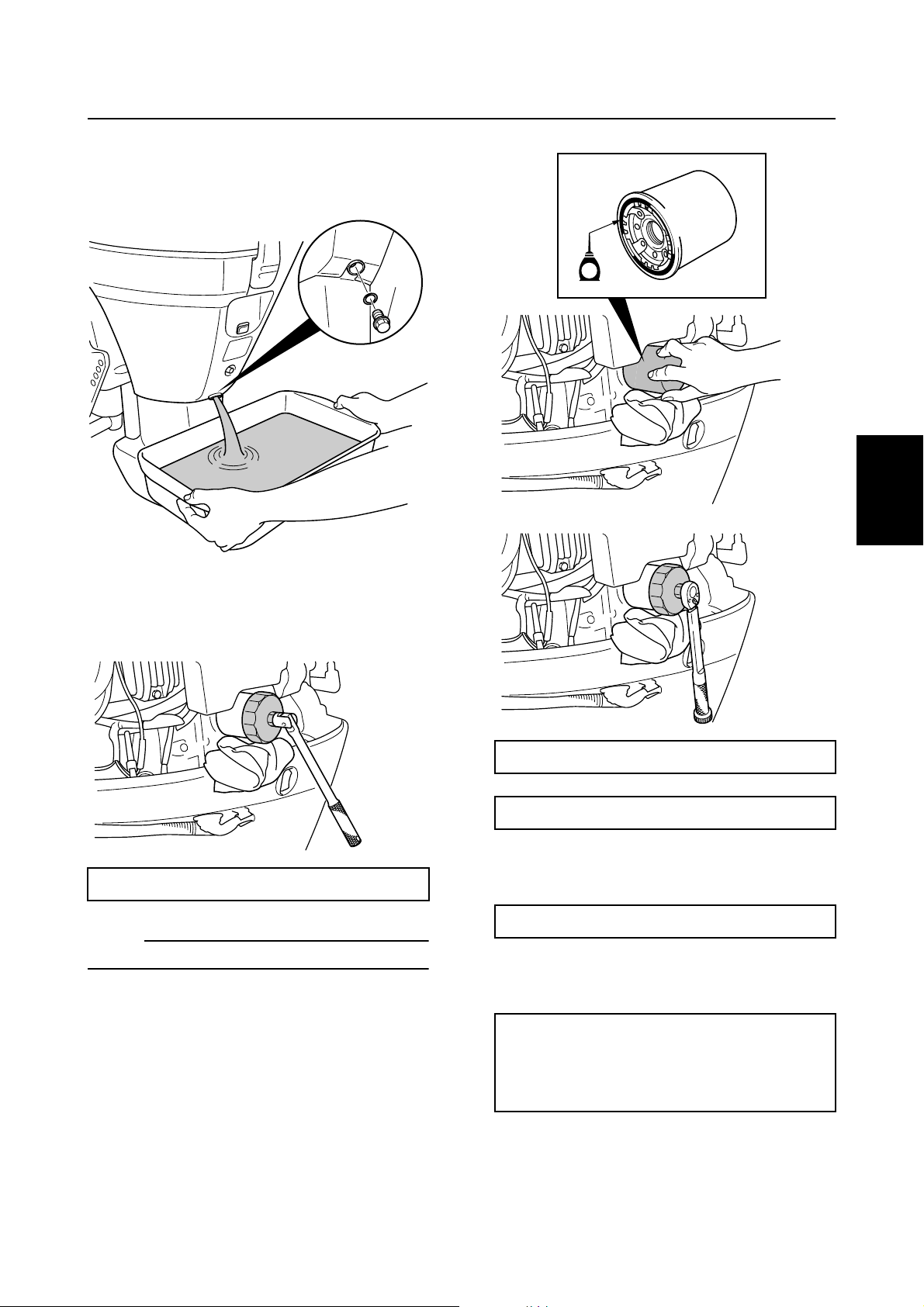
2. Place a drain pan under the drain hole,
and then remove the drain bolt 2 and let
the oil drain completely.
Fuel system / Power unit
2
S62Y3080
3. Place a rag under the oil filter, and then
remove the filter.
E
1
2
S62Y3110
3
4
S62Y3115
S62Y3100
Oil filter wrench: YU-38411 / 90890-01426
NOTE:
Be sure to clean up any oil spills.
4. Apply a thin coat of the new engine oil to
the O-ring of the new oil filter.
5. Install the oil filter, and then tighten it to
the specified torque.
Oil filter wrench: YU-38411 / 90890-01426
Oil filter: 18 N·m (1.8 kgf·m, 13 ft·lb)
6. Install the drain bolt, and then tighten it to
the specified torque.
Drain bolt: 18 N·m (1.8 kgf·m, 13 ft·lb)
7. Fill the specified engine oil into the oil
filler hole.
Recommended engine oil:
4-stroke motor oil
API: SE, SF, SG, or SH
SAE: 10W-30, 10W-40, or 20W-40
5
6
7
8
62Y3A11
3-6
I
Page 82
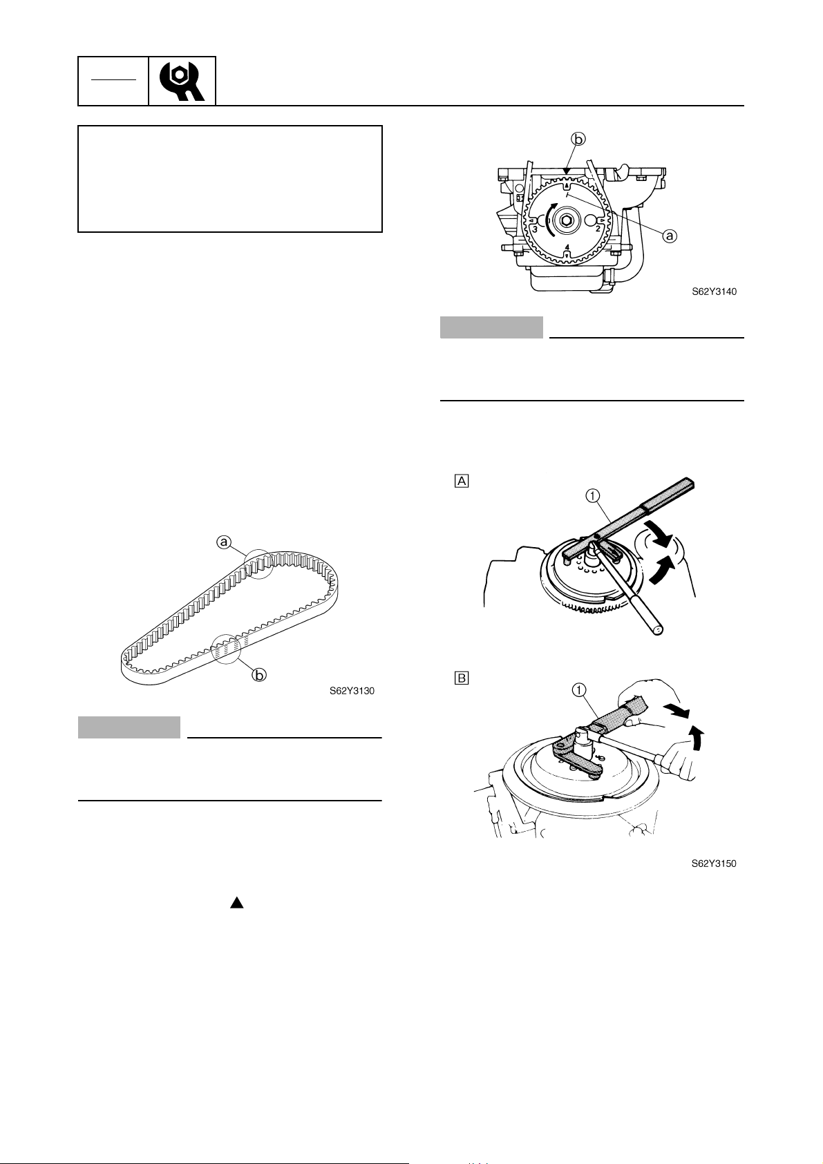
CHK
ADJ
Oil quantity:
With oil filter replacement:
2.2 L (2.3 US qt, 1.9 Imp qt)
Without oil filter replacement:
2.0 L (2.1 US qt, 1.8 Imp qt)
8. Install the oil filler cap and dipstick, and
then start the engine and warm it up for 5
minutes.
Periodic checks and adjustments
9. Turn the engine off, and then check the
oil level and correct it if necessary.
Checking the timing belt
1. Remove the flywheel magnet cover.
2. While turning the flywheel magnet clockwise, check the interior a and the exterior b of the timing belt for cracks,
damage, or wear. Replace if necessary.
CAUTION:
Do not turn the flywheel magnet counterclockwise, otherwise the valve system
may be damaged.
CAUTION:
Do not turn the flywheel magnet counterclockwise, otherwise the valve system
may be damaged.
2. Remove the flywheel magnet.
Replacing the timing belt
1. Turn the flywheel magnet clockwise and
align the “1” mark a on the driven
sprocket with the “” mark b on the cylinder head.
3-7
62Y3A11
Page 83
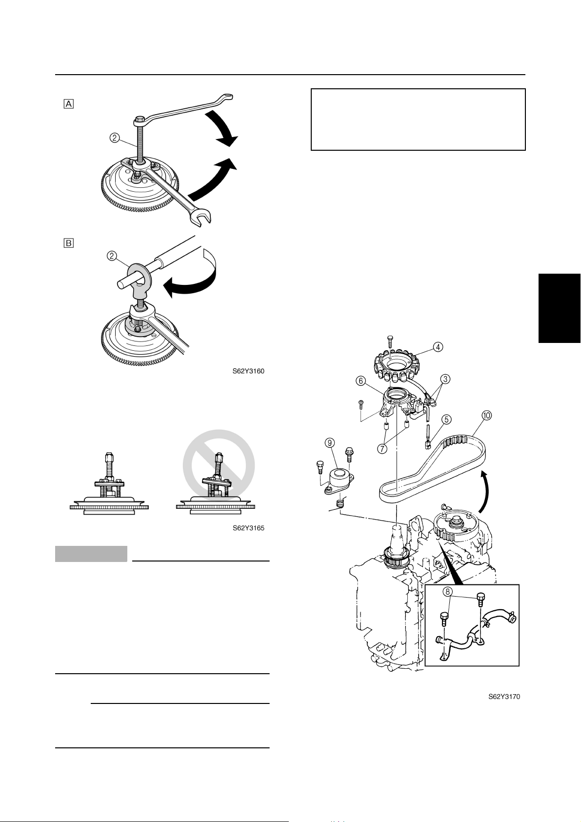
Power unit
Flywheel magnet holder 1: YB-06139
Flywheel holder 1: 90890-06522
Universal puller 2: YB-06117
Flywheel puller 2: 90890-06521
For USA and Canada
È
For worldwide
É
3. Disconnect the stator couplers 3, and
then remove the stator 4.
4. Disconnect the pulser coil coupler 5,
and then remove the stator base 6 with
both collars 7.
5. Remove the blowby hose bolts 8 and
tensioner 9, then the timing belt 0 from
the driven sprocket side.
1
2
3
4
CAUTION:
• Apply force in the direction of the
arrows shown, to prevent the flywheel
holder from slipping off easily.
• To prevent damage to the engine or
tools, screw in the flywheel puller set
bolts evenly and completely so that the
flywheel puller plate is parallel to the flywheel magnet.
NOTE:
Apply force to the crankshaft end until the flywheel magnet comes off the tapered portion
of the crankshaft.
5
6
7
8
62Y3A11
3-8
I
Page 84
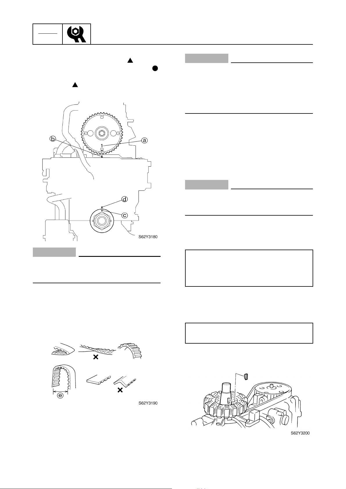
CHK
ADJ
6. Check that the “1” mark a on the driven
sprocket is aligned with the “” mark
on the cylinder head, and that the “”
mark c on the drive sprocket is aligned
with the “” mark d on the crankcase.
Align if necessary.
Periodic checks and adjustments
b
CAUTION:
• Do not twist, turn inside out, or bend the
timing belt beyond the maximum limit of
25 mm (1.0 in) e, otherwise it may be
damaged.
• Do not get oil or grease on the timing
belt.
8. Install the tensioner and bolts, and then
tighten the bolts finger tight.
9. Turn the drive sprocket clockwise two
turns, and then check that the alignment
marks are aligned.
CAUTION:
Do not turn the sprockets counterclockwise, otherwise the valve system may be
damaged.
CAUTION:
Do not turn the sprockets counterclockwise, otherwise the valve system may be
damaged.
7. While pushing against the tensioner side
of the belt, install the new timing belt from
the drive sprocket side with its part number in the upright position.
10. Tighten the tensioner bolts to the specified torque.
Tensioner bolt:
8 N·m (0.8 kgf·m, 5.8 ft·lb)
Tensioner bolt (adjusting bolt):
25 N·m (2.5 kgf·m, 18 ft·lb)
11. Install the blowby hose bolts, stator base
with both collars and stator, and then
connect the couplers.
Stator base screw:
4 N·m (0.4 kgf·m, 2.9 ft·lb)
12. Install the Woodruff key.
3-9
62Y3A11
Page 85
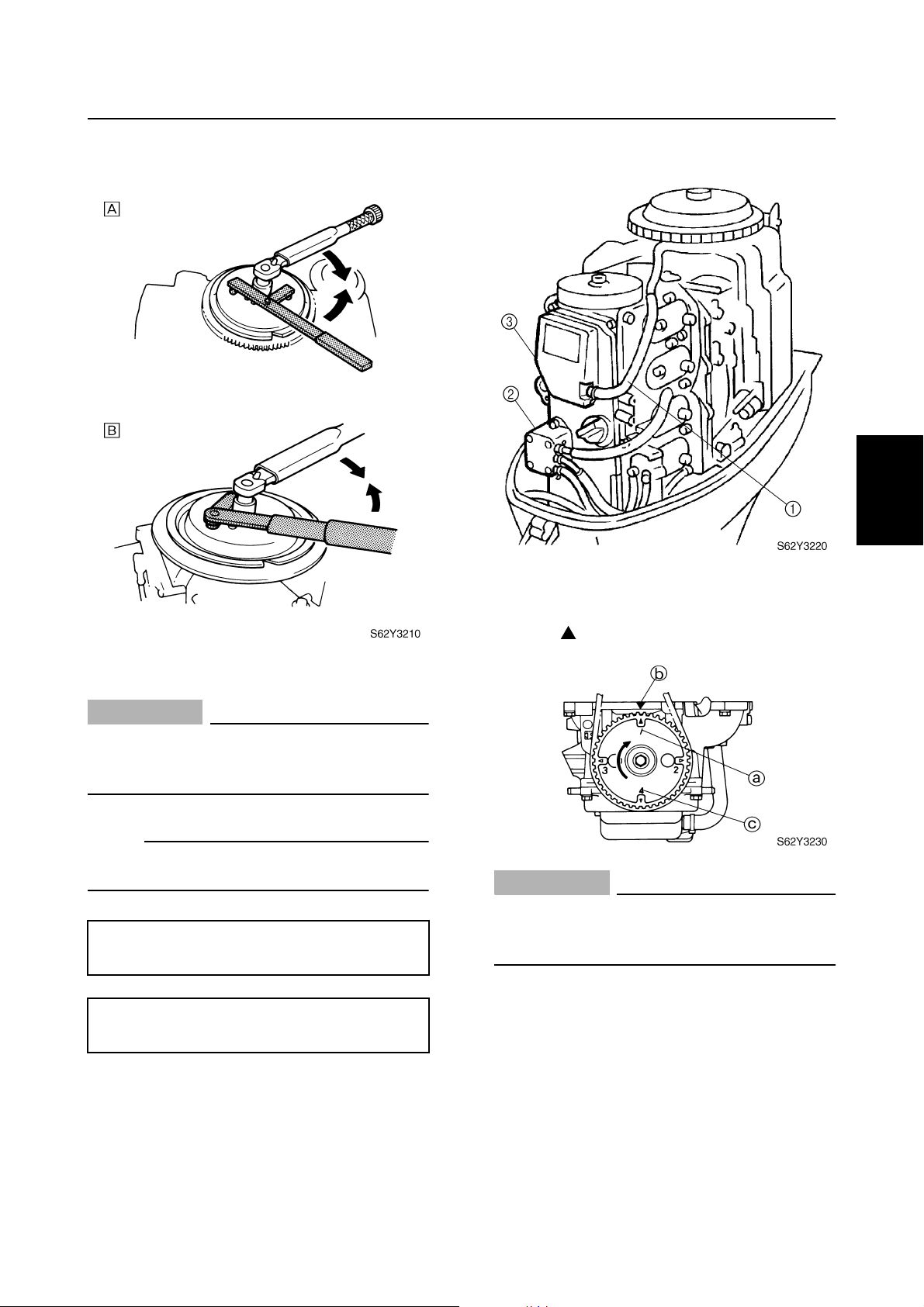
Power unit
13. Install the flywheel magnet and flywheel
magnet cover.
For USA and Canada
È
For worldwide
É
2. Remove the spark plugs, fuel pump 2,
and cylinder head cover 3.
3. Turn the flywheel clockwise and align the
“1” mark a on the driven sprocket with
the “” mark b on the cylinder head.
1
2
3
4
CAUTION:
Apply force in the direction of the arrows
shown, to prevent the flywheel holder
from slipping off easily.
NOTE:
Apply engine oil to the flywheel magnet nut
before installation.
Flywheel magnet holder: YB-06139
Flywheel holder: 90890-06522
Flywheel magnet nut:
160 N·m (16 kgf·m, 116 ft·lb)
Checking the valve clearance
1. Remove the flywheel magnet cover, and
then disconnect the high-tension cords
and blowby hose 1.
CAUTION:
Do not turn the flywheel counterclockwise, otherwise the valve system may be
damaged.
4. Check the intake valve clearance for cylinders #1 and #2, and the exhaust valve
clearance for cylinders #1 and #3. Adjust
if necessary.
5
6
7
8
62Y3A11
3-10
I
Page 86
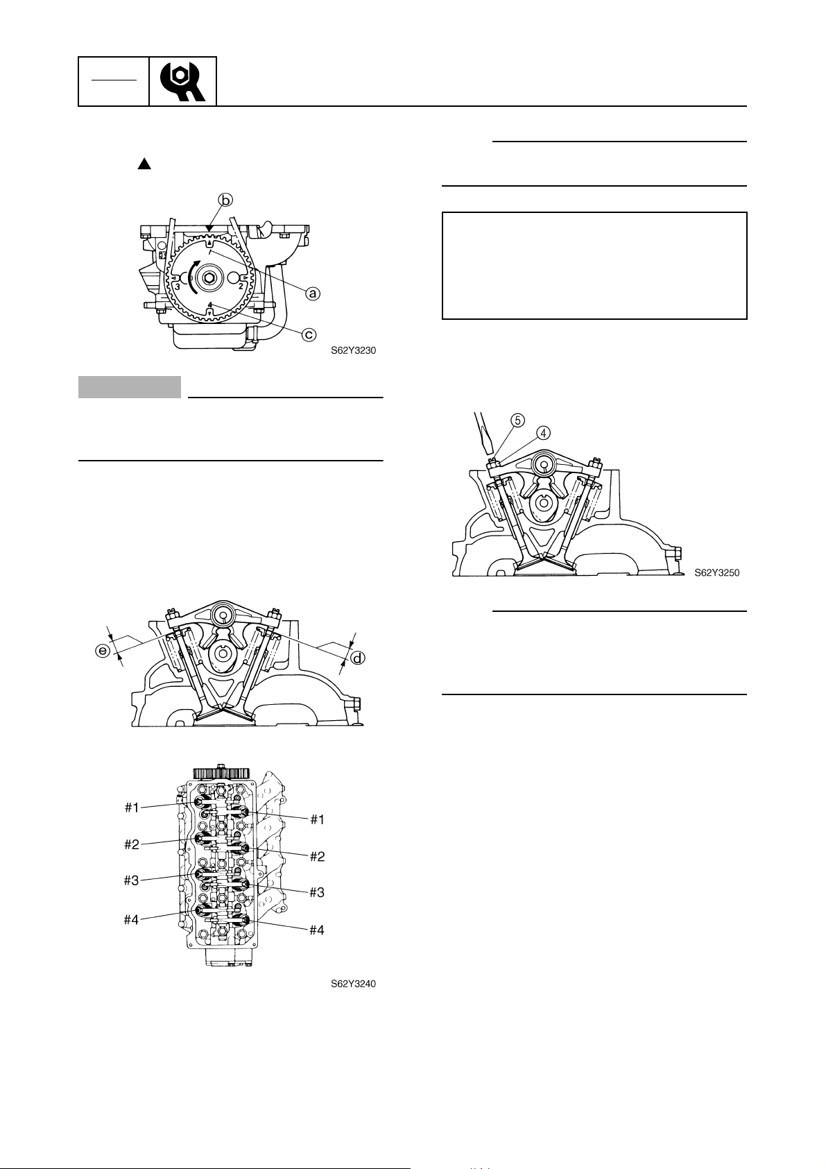
CHK
ADJ
Periodic checks and adjustments
5. Turn the flywheel clockwise and align the
“4” mark c on the driven sprocket with
the “” mark b on the cylinder head.
CAUTION:
Do not turn the flywheel counterclockwise, otherwise the valve system may be
damaged.
6. Check the intake valve clearance for cylinders #3 and #4, and the exhaust valve
clearance for cylinders #2 and #4. Adjust
if out of specification.
NOTE:
Adjust the valve clearance when the engine
is cold.
Valve clearance:
Intake d:
0.20 ± 0.05 mm (0.008 ± 0.002 in)
Exhaust e:
0.30 ± 0.05 mm (0.012 ± 0.002 in)
7. Loosen the locknut 4, and then turn the
adjusting screw 5 until the specified
valve clearance is obtained.
NOTE:
• To decrease the valve clearance, turn the
adjusting screw clockwise.
• To increase the valve clearance, turn the
adjusting screw counterclockwise.
8. Tighten the locknut, and then check the
valve clearances. Adjust if necessary.
9. Install the cylinder head cover, fuel
pump, and spark plugs.
10. Connect the blowby hose and high-tension cords, and then install the flywheel
magnet cover.
Checking the spark plugs
1. Disconnect the high-tension cords, and
then remove the spark plugs.
3-11
62Y3A11
Page 87
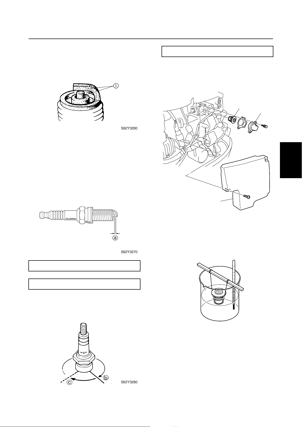
2. Clean the electrodes 1 with a spark plug
cleaner or wire brush. Replace the spark
plug if necessary.
Power unit
Spark plug: 18 N·m (1.8 kgf·m, 13 ft·lb)
Checking the thermostat
1. Remove the cover 1, thermostat cover
2
, and thermostat 3.
1
3. Check the electrodes for erosion and
excessive carbon or other deposits, and
the gasket for damage. Replace the
spark plug if necessary.
4. Check the spark plug gap a. Adjust if out
of specification.
3
2
1
S62Y3290
2. Suspend the thermostat in a container of
water.
3. Place a thermometer in the water and
slowly heat the water.
2
3
4
5
Specified spark plug: DPR6EA-9 (NGK)
Spark plug gap a: 0.9 mm (0.035 in)
5. Install the spark plug, tighten it finger
tight b, then to the specified torque with
a spark plug wrench c.
62Y3A11
S62Y3300
3-12
6
7
8
I
Page 88
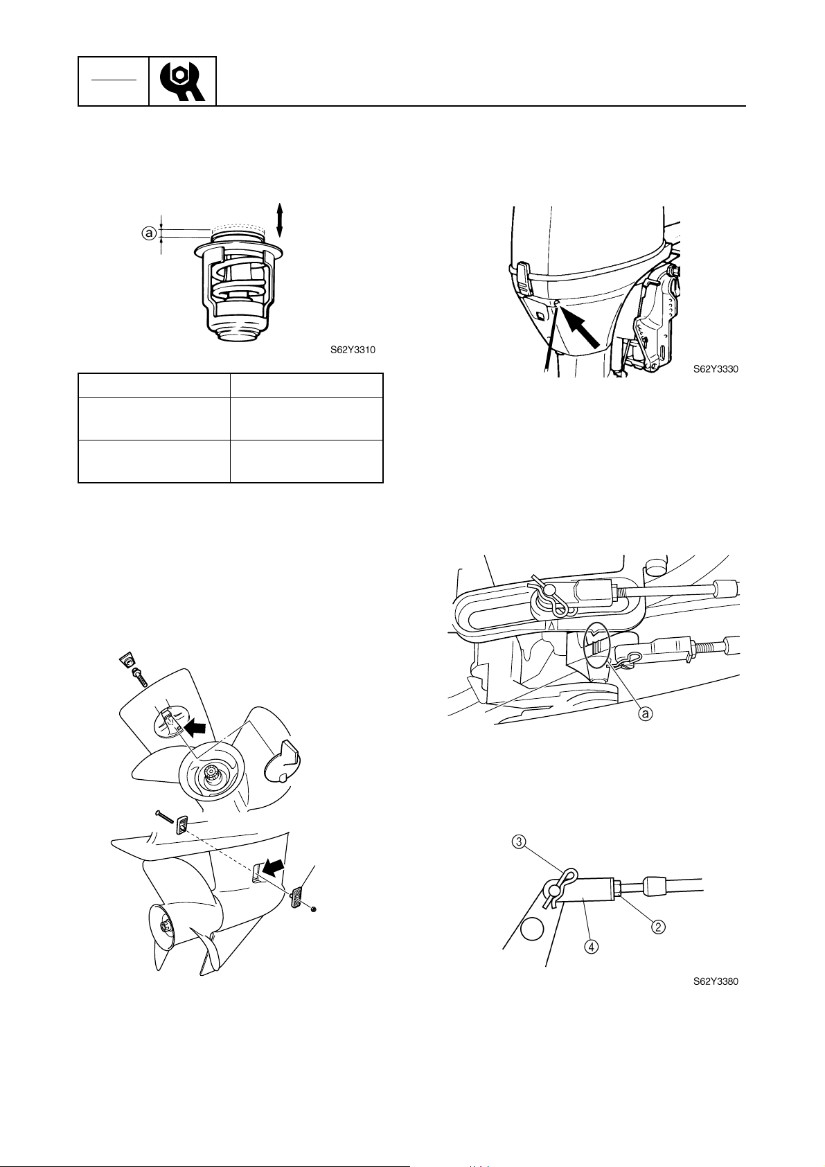
CHK
ADJ
Periodic checks and adjustments
4. Check the thermostat valve opening at
the specified water temperatures.
Replace if out of specification.
Water temperature Valve lift a
below
60 °C (140 °F)
above
70 °C (158 °F)
0 mm (0 in)
more than
3 mm (0.12 in)
5. Install the thermostat, new gasket, thermostat cover, and cover.
3. Check for water flow at the cooling water
outlet. If there is no water flow, check the
cooling water passage inside the outboard.
Control system
Checking the throttle cable operation
1. Check that the throttle cam 1 is at the
fully closed position a when the remote
control lever is in neutral or the throttle
grip is fully closed. Adjust the throttle
cable length if necessary as follows.
3
Checking the cooling water passage
1. Check the cooling water inlet cover
and cooling water inlet for clogs. Clean if
necessary.
1
1
S62Y3320
1
1
S62Y3370
2. Loosen the locknut 2, remove the clip
3
, and then disconnect the throttle cable
joint 4.
2. Place the lower unit in water, and then
start the engine.
3-13
62Y3A11
Page 89
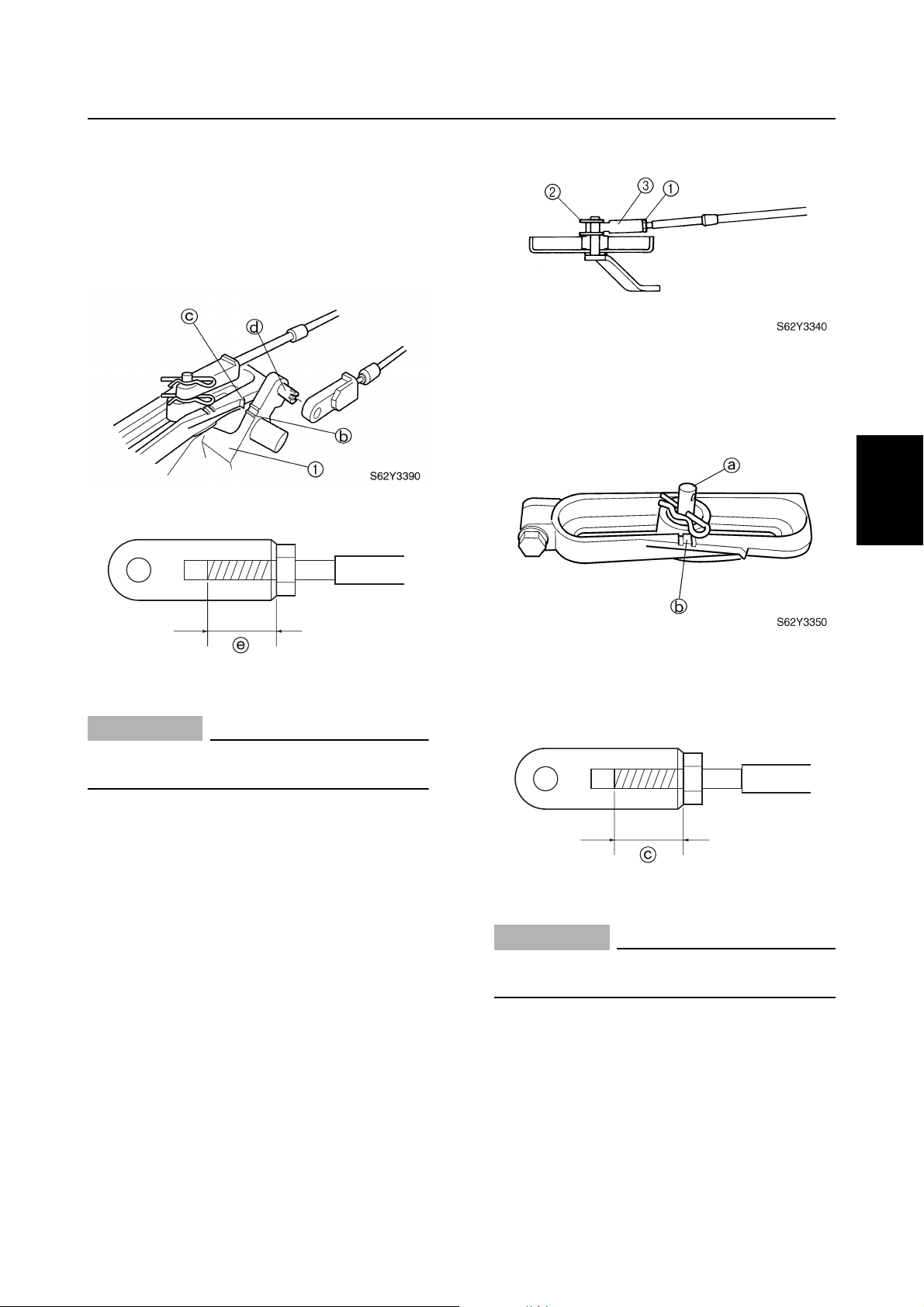
3. Align the alignment mark b on the throttle cam 1 with the alignment mark c on
the shift bracket.
4. Adjust the position of the throttle cable
joint until its hole is aligned with the set
pin d on the throttle cam.
Power unit / Control system
4. Align the set pin a in the center of the
shift bracket with the alignment mark
on the bracket.
b
1
2
3
S62Y3400
CAUTION:
The throttle cable joint must be screwed
in a minimum of 8.0 mm (0.31 in) e.
5. Connect the cable joint, install the clip,
and then tighten the locknut.
6. Check the throttle cable for smooth operation and adjust the cable length, if necessary, repeating steps 2–6.
Checking the gearshift operation
1. Check that the gearshift operates
smoothly when shifting from neutral into
forward and reverse. Adjust the shift
cable length if necessary.
5. Adjust the position of the shift cable joint
until its hole is aligned with the set pin.
S62Y3360
CAUTION:
The shift cable joint must be screwed in a
minimum of 8.0 mm (0.31 in) c.
6. Connect the cable joint, install the clip,
and then tighten the locknut.
4
5
6
7
2. Set the gearshift to the neutral position.
3. Loosen the locknut 1, remove the clip
2
, and then disconnect the shift cable
joint 3.
62Y3A11
7. Check the gearshift for smooth operation
and adjust the shift cable length, if necessary, repeating steps 3–6.
3-14
8
I
Page 90
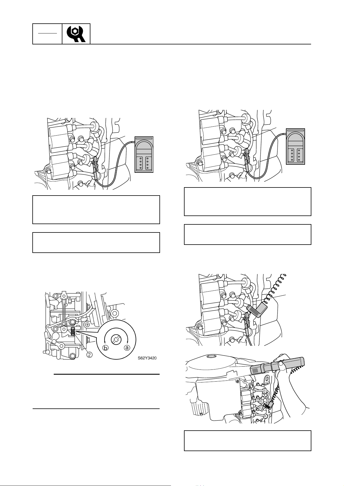
CHK
ADJ
Periodic checks and adjustments
Checking the engine idle speed
1. Start the engine and warm it up for 5 minutes.
2. Attach the special service tool to hightension cord #1 1, and then check the
engine idle speed. Adjust if out of specification.
1
S62Y3410
Inductive self-powered tachometer:
YU-08036-B
Digital tachometer: 90890-06760
Checking the ignition timing
1. Start the engine and warm it up for 5 minutes.
2. Attach the special service tool to hightension cord #1 1, and then check the
engine idle speed.
1
S62Y3430
Inductive self-powered tachometer:
YU-08036-B
Digital tachometer: 90890-06760
Engine idle speed:
750 ± 50 (950 ± 50) r/min
3. Turn the throttle stop screw 2 in direction a or b until the specified engine
idle speed is obtained.
NOTE:
• To increase the idle speed, turn the throttle
stop screw in direction a.
• To decrease the idle speed, turn the throttle
stop screw in direction b.
Engine idle speed:
750 ± 50 (950 ± 50) r/min
3. Attach the special service tool to hightension cord #1 1.
1
S62Y3440
4. After adjusting the idle speed, rev the
engine a few times and let it idle for at
least 15 seconds to check the stability of
the engine.
3-15
S62Y3450
Battery powered timing light: YM-33277-A
Timing light: 90890-03141
62Y3A11
Page 91
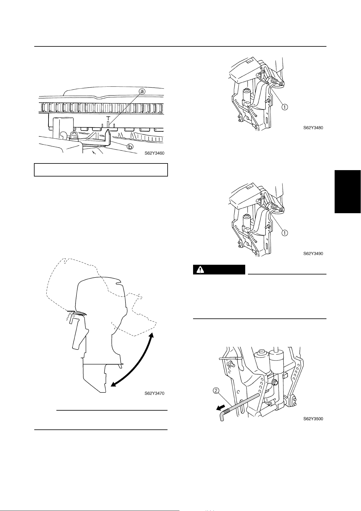
4. Check that the TDC “T” mark a on the
flywheel magnet is aligned with the magnet base pointer b.
Ignition timing: BTDC 5 ± 3°
Control system / Power trim and tilt unit
Checking the power trim and tilt fluid
level
1. Fully tilt the outboard up, and then support it with the tilt stop lever 1.
1
2
Power trim and tilt unit
Checking the power trim and tilt
operation
1. Fully tilt the outboard up and down a few
times and check the entire trim and tilt
range for smooth operation. Check the
power trim and tilt fluid level if necessary.
3
3
4
WARNING
After tilting up the outboard, be sure to
support it with the tilt stop lever.
Otherwise, the outboard could suddenly
lower if the power trim and tilt unit should
lose fluid pressure.
2. Remove the tilt pin 2.
5
6
NOTE:
Be sure to listen to the winding sound of the
PTT motor for smooth operation.
2. Fully tilt the outboard up, and then support it with the tilt stop lever 1 to check
the lock mechanism of the lever.
62Y3A11
3-16
7
8
I
Page 92
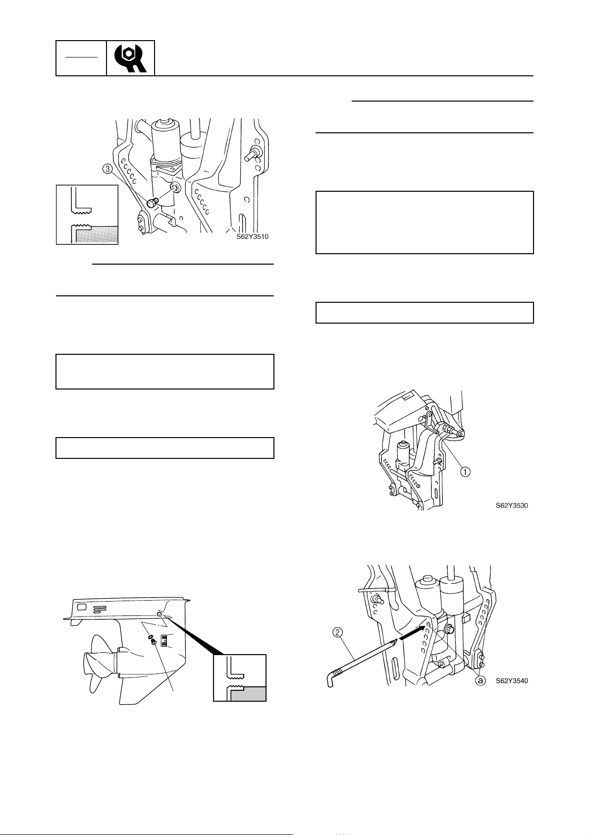
CHK
ADJ
Periodic checks and adjustments
3. Remove the reservoir cap 3, and then
check the fluid level in the reservoir.
NOTE:
The fluid level should be at the brim of the
filler hole.
4. If necessary, add sufficient fluid of the
recommended type to the correct level.
Recommended power trim and tilt fluid:
ATF Dexron II
NOTE:
The gear oil level should be at the brim of the
check hole.
3. If necessary, add sufficient gear oil of the
recommended type to the correct level.
Recommended gear oil:
GEAR CASE LUBE (USA) or Hypoid
gear oil
SAE: 90
4. Install the check screw, and then tighten
it to the specified torque.
Check screw: 7 N·m (0.7 kgf·m, 5.1 ft·lb)
Replacing the gear oil
1. Fully tilt the outboard up, and then support it with the tilt stop lever 1.
5. Install the reservoir cap, and then tighten
it to the specified torque.
Reservoir cap: 8 N·m (0.8 kgf·m, 5.8 ft·lb)
6. Install the tilt pin to its original position.
Lower unit
Checking the gear oil level
1. Fully tilt the outboard down.
2. Remove the check screw 1, and then
check the gear oil level in the lower case.
1
S62Y3520
3
2. Remove the tilt pin 2, and then install it
in the upper tilt pin hole a.
3. Release the tilt stop lever and tilt the outboard down until it contacts the tilt pin.
3-17
62Y3A11
Page 93
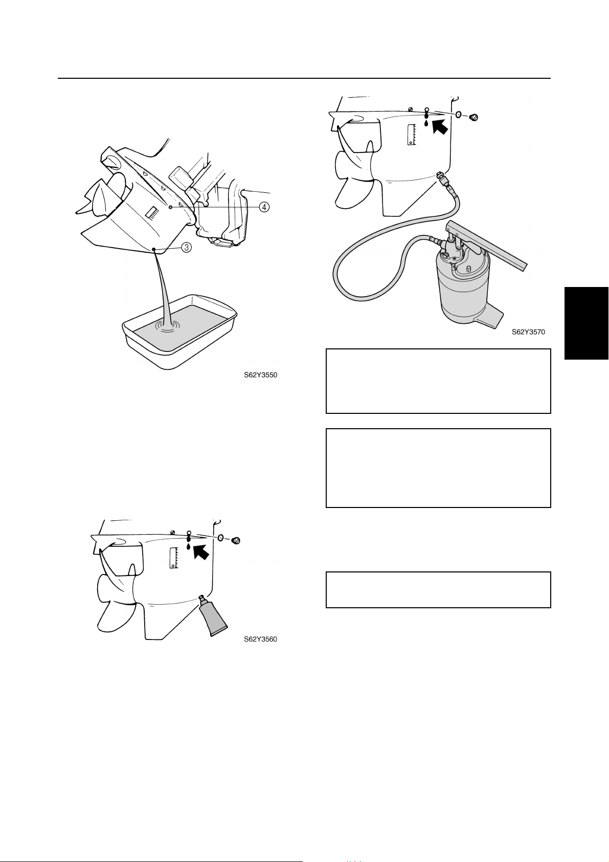
4. Place a drain pan under the drain screw
3
, remove the drain screw, then the
check screw 4 to drain the oil.
5. Check the oil for metal, discoloration, and
viscosity. Check the internal parts of the
lower case if necessary.
6. Insert the gear oil tube or gear oil pump
into the drain hole and slowly fill the gear
oil until oil flows out of the check hole and
no air bubbles are visible.
Power trim and tilt unit / Lower unit
Recommended gear oil:
GEAR CASE LUBE (USA) or Hypoid
gear oil
SAE: 90
Oil quantity:
F50/F50A:
0.43 L (0.45 US qt, 0.38 Imp qt)
T50/FT50B, FT50C:
0.61 L (0.64 US qt, 0.54 Imp qt)
1
2
3
4
5
62Y3A11
7. Install the check screw, quickly install the
drain screw, and then tighten them to the
specified torque.
Check and drain screw:
7 N·m (0.7 kgf·m, 5.1 ft·lb)
3-18
6
7
8
I
Page 94
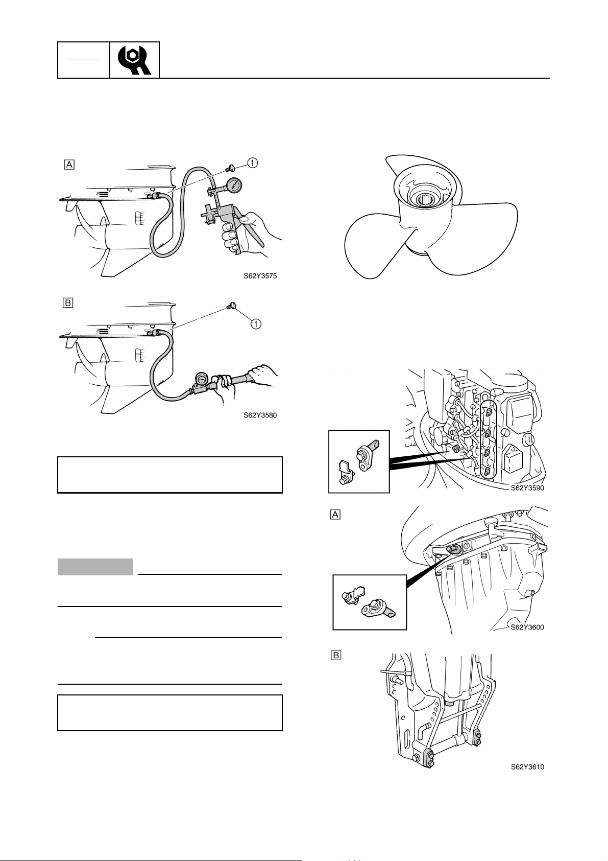
CHK
ADJ
Periodic checks and adjustments
Checking the lower unit
(for air leakage)
1. Remove the check screw 1, and then
install the special service tool.
Checking the propeller
1. Check the propeller blades and splines
for cracks, damage, or wear. Replace if
necessary.
S62Y3585
General
Checking the anodes
1. Check the anodes and trim tab for
scales, grease, or oil. Clean if necessary.
3
For USA and Canada
È
For worldwide
É
Pressure/vacuum tester: YB-35956-A
Leakage tester: 90890-06762
2. Apply the specified pressure to check
whether the lower unit can hold it for at
least 10 seconds.
CAUTION:
Do not over pressurize the lower unit, otherwise the oil seals may be damaged.
NOTE:
Cover the check hole with a rag when removing the pressure/vacuum tester from the
lower unit.
Lower unit holding pressure:
100 kPa (1.0 kgf/cm
2
, 14 psi)
3. If pressure drops below specification,
check the drive shaft and propeller shaft
oil seals for damage.
3-19
62Y3A11
Page 95
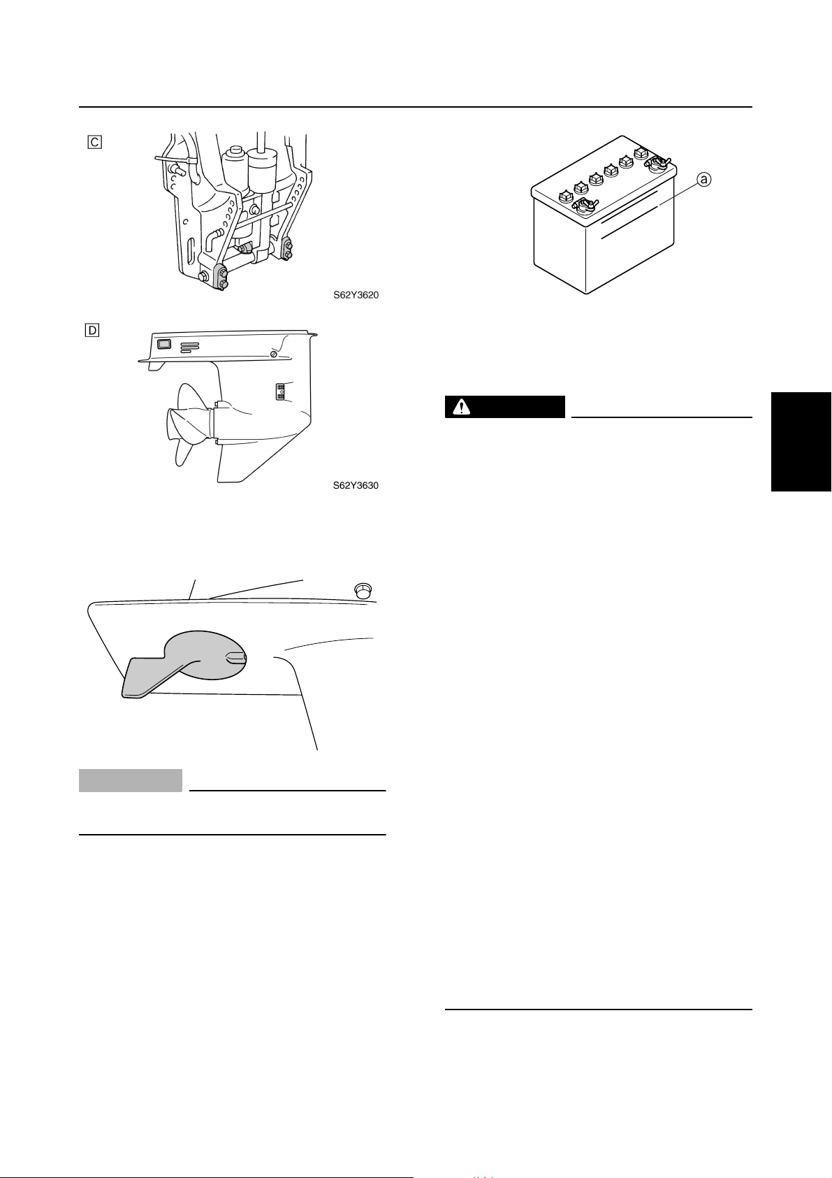
FT50C only
È
EHD, ED models
É
EHT, ET models
Ê
F50/F50A only
Ë
S62Y3640
CAUTION:
Do not oil, grease, or paint the anodes,
otherwise they will be ineffective.
2. Replace the anodes and trim tab if
excessively eroded.
Checking the battery
1. Check the battery electrolyte level. If the
level is at or below the minimum level
mark a, add distilled water until the level
is between the maximum and minimum
level marks.
Lower unit / General
S62Y3650
2. Check the specific gravity of the electrolyte. Fully charge the battery if out of
specification.
WARNING
Battery electrolyte is dangerous; it contains sulfuric acid which is poisonous and
highly caustic.
Always follow these preventive measures:
• Avoid bodily contact with electrolyte as
it can cause severe burns or permanent
eye injury.
• Wear protective eye gear when handling
or working near batteries.
Antidote (EXTERNAL):
• SKIN – Wash with water.
• EYES – Flush with water for 15 minutes
and get immediate medical attention.
Antidote (INTERNAL):
• Drink large quantities of water or milk
followed with milk of magnesia, beaten
egg, or vegetable oil. Get immediate
medical attention.
Batteries generate explosive, hydrogen
gas. Always follow these preventive measures:
• Charge batteries in a well-ventilated
area.
• Keep batteries away from fire, sparks or
open flames (e.g., welding equipment,
lighted cigarettes).
• DO NOT SMOKE when charging or han-
dling batteries.
KEEP BATTERIES AND ELECTROLYTE
OUT OF REACH OF CHILDREN.
1
2
3
4
5
6
7
8
62Y3A11
3-20
I
Page 96
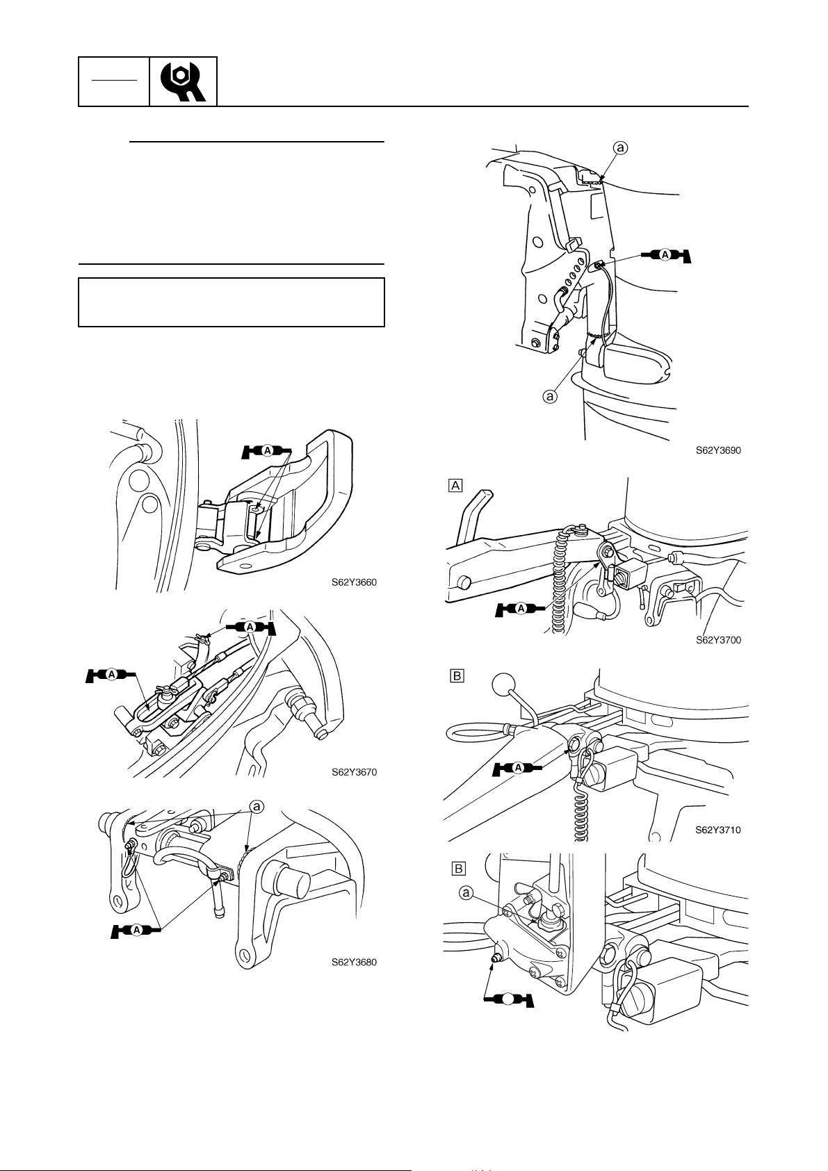
CHK
ADJ
NOTE:
• Batteries vary per manufacturer. The procedures mentioned in this manual may not
always apply, therefore, consult the instruction manual of the battery.
• Disconnect the negative lead first, then the
positive lead.
Electrolyte specific gravity:
1.280 at 20 °C (68 °F)
Lubrication
1. Apply water resistant grease to the areas
shown.
Periodic checks and adjustments
3-21
A
F50/F50A, T50/FT50B
È
FT50C
É
S62Y3720
62Y3A11
Page 97
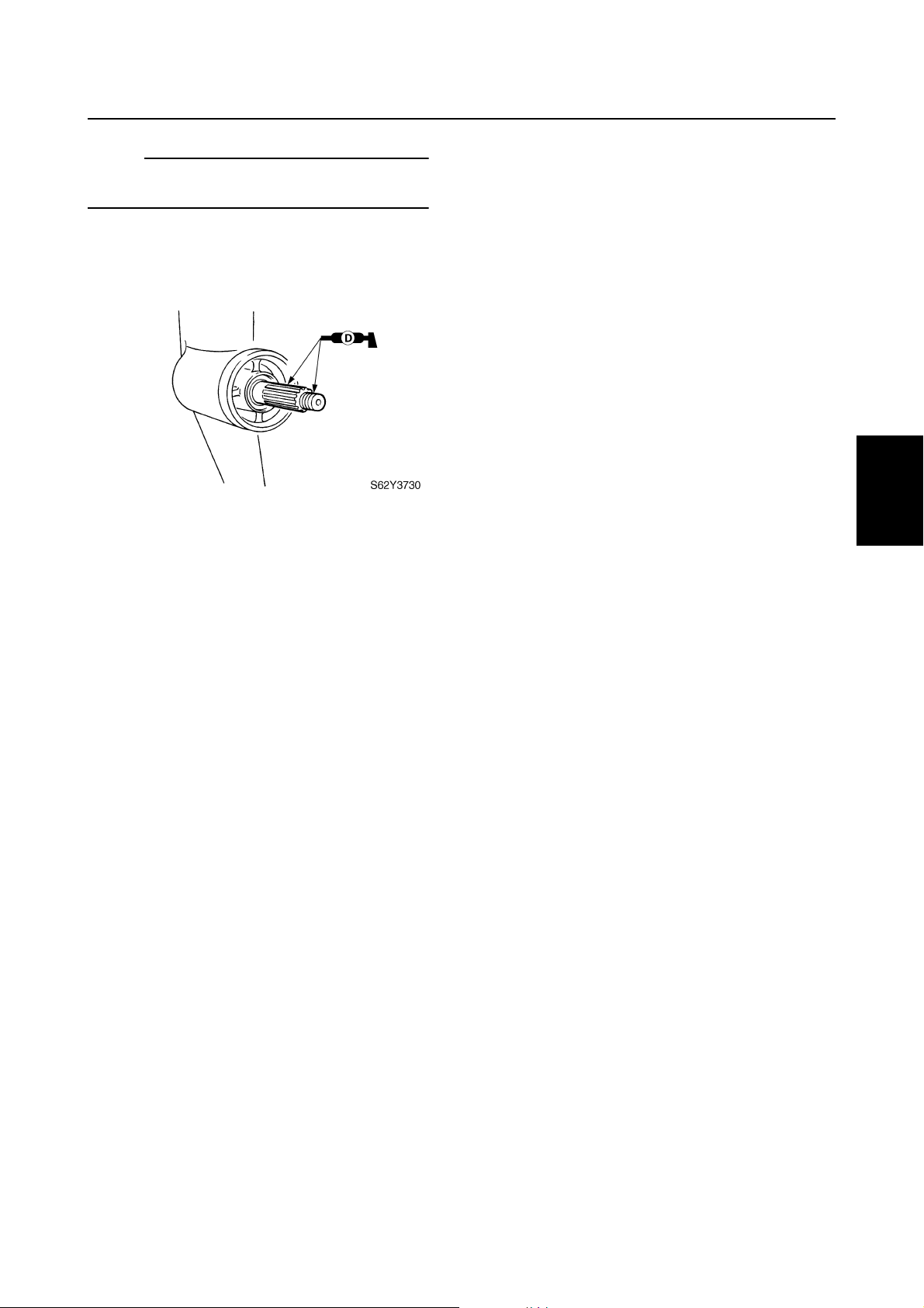
NOTE:
Apply grease to the grease nipple until it
flows from the bushings a.
2. Apply anti-corrosion grease to the areas
shown.
General
1
2
3
4
5
6
7
62Y3A11
3-22
8
I
Page 98

CHK
ADJ
Periodic checks and adjustments
— MEMO —
3-23
62Y3A11
Page 99
FUEL
Fuel system
Special service tools .....................................................................................4-1
Hose routing...................................................................................................4-2
Fuel and blowby hoses..............................................................................4-2
Cooling water hose....................................................................................4-3
Fuel line ..........................................................................................................4-5
Fuel filter and fuel pump ...............................................................................4-7
Checking the fuel pump.............................................................................4-9
Disassembling the fuel pump ....................................................................4-9
Checking the diaphragm and valves .......................................................4-10
Assembling the fuel pump .......................................................................4-10
1
2
Carburetor unit.............................................................................................4-11
Carburetor.....................................................................................................4-17
Checking the carburetor ..........................................................................4-19
Checking the Prime Start.........................................................................4-20
Assembling the carburetor.......................................................................4-20
Adjusting the throttle link rod ...................................................................4-21
Adjusting the pilot screw..........................................................................4-22
Synchronizing the carburetors.................................................................4-23
Adjusting the dash-pot (acceleration pump) ............................................ 4-24
3
4
5
6
62Y3A11
7
8
I
Page 100
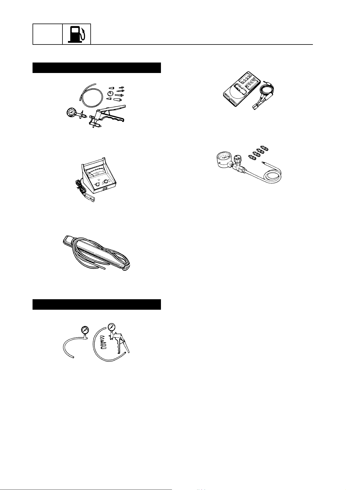
FUEL
Fuel system
Special service tools
For USA and Canada
Pressure/vacuum tester
YB-35956-A
Inductive self-powered tachometer
YU-08036-B
4
Digital tachometer
90890-06760
Vacuum gauge
90890-03159
Carburetor synchronizer
YU-08030
For worldwide
Vacuum/pressure pump gauge set
90890-06756
4-1
62Y3A11
 Loading...