

Optional Boards
for
DSP UNIT
hank you for choosing the board for Yamaha DSP1D (DSP unit).
T
Ask an authorized Yamaha service engineer to install the board. Do not install the board yourself.
の度はヤマハDSPユニットDSP1D用ボードをお買上げいただき、ありがとうございます 。
ここ
ボードの取付けは、必ずヤマハサービスエンジニアにご依頼ください。お客様ご自身では行なわないでください。
The following items are optional boards available for the DSP1D.
DSP1D用にオプションでお求めいただけるボードは次のとおりです。
INPUT DSP BOARD インプットDSPボード IDB1D
CONSOLE INTERFACE BOARD コ ンソ ールインタ フェースボー ド CIB1D
ENGINE MANAGEMENT BOARD エンジンマネージメントボード EMB1D
PATCH DSP BOARD パッチDSPボー ド PDB1D
GROUP DSP BOARD グループDSPボード GDB1D
EFFECT DSP BOARD エフェ クトDSPボード EDB1D
■ Installing the board (For only an authorized Yamaha service engineers)
ボード装着手順(ヤマハサービスエンジニア用)
Before installing the board, be sure to turn off the power to the DSP1D and disconnect the power cord.
You need to remove the front cover of the DSP1D to install any board. To install the PDB1D board, you also need to remove the
left side cover.
ボードの装着作業は必ずDSP1Dの電源スイッチを切り、電源コード を抜いてから行なってくださ い。
パッチDSPボードPDB1D以外のボードの装着はユニット 正面のカバーを取り はずして行ないます。PDB1Dボードの装着はさらにユニット
左側面カバーのとりはずしが必要です。
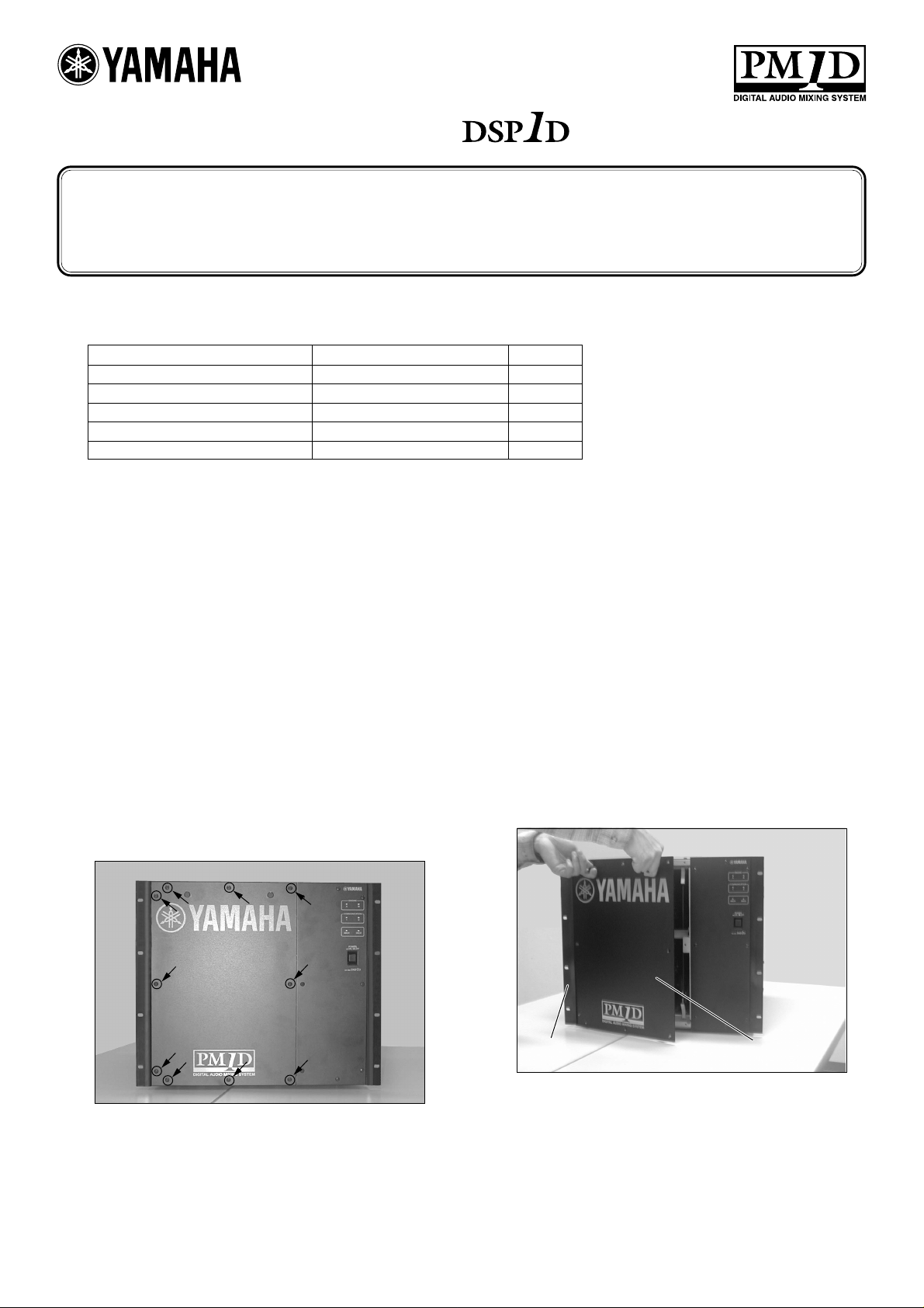
1. Remove ten screws as
shown in the picture. Do
not remove any other
screws. Keep the removed screws in a safe
place since you will need
them to re-attach the
cover.
10ヶ所のネジをはずします。写
真に示した以外のネ ジははず さ
ないでください。また取りはずし
たネジはカバーを再び取り付け
る際、必要ですので紛失しない
でく ださい。
2. As shown in the picture,
remove the cover by
opening from the right
side to avoid damage to
the hardware on the left
side of the rack.
左側ラック金具を破損しないよ
う写真のよう に正面カバーを右
側から先に開けて取り はずしま
す。
左側ラック金具
hardware on the left side of the rack
正面カバー
front cover
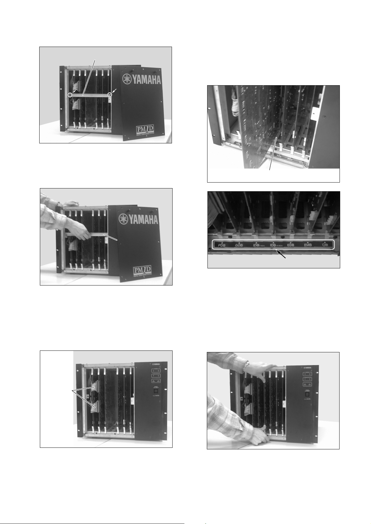
3. Loosen two screws on the
protect bar.
保護バーの2ヶ所のネジを少し
ゆるめます。
保護バー
protectbar
6. Slide the board into the
slot along the upper and
lower guide rails.
The sliding position is labelled with the corresponding board model
name.
装着するスロット内の上と下に
あるガイドレールにボードを沿
わせてボードを挿入します。
各ボードの挿入位置はここに
ボードのモデル名がありますの
でこれに従ってください。
4. Lift up the protect bar and
remove it.
5. If you are replacing the
PDB1D board and the
GDB1D board, remove
two connecting ribbon
cables.
写真のように保護バーを上に持
ち上げながらはずします。
保護バー
protectbar
PDB1DボードおよびGDB1D
ボードを交換の際は接続されて
いるフラットケーブ ルを 2 本 取り
はずします。
7. Press both edges of the
board firmly and slide the
board all the way into the
slot.
Reverse these steps to reinstall the protect bar and
the front cover.
ガイドレール
guiderail
写真のようにボードの両端を強
く押しボードをスロットの 奥に確
実に差し込みます。
前述の手順の逆で保護バー、正
面カバーを再び取 り付けてくだ
さい。
接続フラット
ケーブル
Connecting
theribbon
cable
2
 Loading...