

Yamaha A5000, A4000 User Manual
SPECIAL MESSAGE SECTION
Rear Panel
PRODUCT SAFETY MARKINGS: Y amaha electronic
products may have either labels similar to the graphics
shown below or molded/stamped facsimiles of these graphics on the enclosure. The explanation of these graphics
appears on this page. Please observe all cautions indicated
on this page and those indicated in the safety instruction section.
CAUTION
RISK OF ELECTRIC SHOCK
DO NOT OPEN
CAUTION: TO REDUCE THE RISK OF ELECTRIC SHOCK.
DO NOT REMOVE COVER (OR BACK).
NO USER-SERVICEABLE PARTS INSIDE.
REFER SERVICING TO QUALIFIED SERVICE PERSONNEL.
The exclamation point within the equilateral triangle is intended to alert the
user to the presence of important operating and maintenance (servicing) instructions in the literature accompanying the
product.
The lightning flash with arrowhead symbol, within the equilateral triangle, is
intended to alert the user to the presence
of uninsulated “dangerous voltage”
within the product’s enclosure that may
be of sufficient magnitude to constitute a
risk of electrical shock.
IMPORTANT NOTICE: All Yamaha electronic products
are tested and approved by an independent safety testing
laboratory in order that you may be sure that when it is properly installed and used in its normal and customary manner,
all foreseeable risks have been eliminated. DO NO T modify
this unit or commission others to do so unless specifically
authorized by Yamaha. Product performance and/or safety
standards may be diminished. Claims filed under the
expressed warranty may be denied if the unit is/has been
modified. Implied warranties may also be affected.
ENVIRONMENTAL ISSUES: Yamaha strives to produce
products that are both user safe and environmentally
friendly. We sincerely believe that our products and the production methods used to produce them, meet these goals. In
keeping with both the letter and the spirit of the law, we
want you to be aware of the following:
Battery Notice: This product MAY contain a small nonrechargable battery which (if applicable) is soldered in
place. The average life span of this type of battery is approximately five years. When replacement becomes necessary,
contact a qualified service representative to perform the
replacement.
Warning: Do not attempt to recharge, disassemble, or incinerate this type of battery. Keep all batteries away from children. Dispose of used batteries promptly and as regulated by
applicable laws. Note: In some areas, the servicer is required
by law to return the defective parts. However, you do have
the option of having the servicer dispose of these parts for
you.
Disposal Notice: Should this product become damaged
beyond repair, or for some reason its useful life is considered to be at an end, please observe all local, state, and federal regulations that relate to the disposal of products that
contain lead, batteries, plastics, etc.
NOTICE: Service charges incurred due to lack of knowledge relating to how a function or effect works (when the
unit is operating as designed) are not covered by the manufacturer’s warranty, and are therefore the owners responsibility. Please study this manual carefully and consult your
dealer before requesting service.
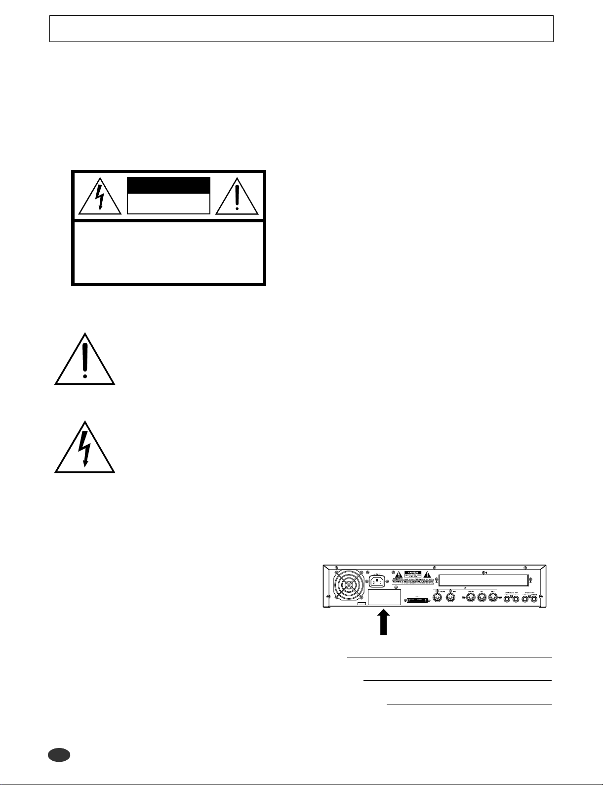
NAME PLATE LOCATION: The graphic below indicates
the location of the name plate. The model number, serial
number, power requirements, etc., are located on this plate.
You should record the model number, serial number , and the
date of purchase in the spaces provided below and retain this
manual as a permanent record of your purchase.
SPECIFICATIONS SUBJECT TO CHANGE: The infor-
Model
mation contained in this manual is believed to be correct at
the time of printing. However, Yamaha reserves the right to
Serial No.
change or modify any of the specifications without notice or
obligation to update existing units.
92-469- ➀ (rear)
2 A5000/A4000 ● ● ● ● ● ● ● ● ● ● ● ● ● ● ● ● ● ● ● ● ● ● ● ● ● ● ● ● ● ● ● ● ● ● ● ● ● ● ● ● ● ● ● ● ● ● ● ● ● ● ● ● ● ● ● ● ● ● ● ● ● ● ● ● ● ● ● ● ●
Purchase Date
PRECAUTIONS
PLEASE READ CAREFULLY BEFORE PROCEEDING
* Please keep these precautions in a safe place for future reference.
WARNING
Always follow the basic precautions listed below to avoid the possibility of serious injury or even death from electrical shock, shortcircuiting, damages, fire or other hazards. These precautions include, but are not limited to, the following:
• Do not open the instrument or attempt to disassemble the internal parts or modify
them in any way. The instrument contains no user-serviceable parts. If it should
appear to be malfunctioning, discontinue use immediately and have it inspected by
qualified Yamaha service personnel.
• Do not expose the instrument to rain, use it near water or in damp or wet conditions,
or place containers on it containing liquids which might spill into any openings.
• If the power cord or plug becomes frayed or damaged, or if there is a sudden loss of
sound during use of the instrument, or if any unusual smells or smoke should
appear to be caused by it, immediately turn off the power switch, disconnect the
electric plug from the outlet, and have the instrument inspected by qualified Yamaha
CAUTION
Always follow the basic precautions listed below to avoid the possibility of physical injury to you or others, or damage to the instrument or other property. These precautions include, but are not limited to, the following:
• Do not place the power cord near heat sources such as heaters or radiators, and do
not excessively bend or otherwise damage the cord, place heavy objects on it, or
place it in a position where anyone could walk on, trip over, or roll anything over it.
• When removing the electric plug from the instrument or an outlet, always hold the
plug itself and not the cord. Pulling by the cord can damage it.
• Do not connect the instrument to an electrical outlet using a multiple-connector.
Doing so can result in lower sound quality , or possibly cause overheating in the outlet.
• Remove the electric plug from the outlet when the instrument is not to be used for
extended periods of time, or during electrical storms.
• Before connecting the instrument to other electronic components, turn off the power
for all components. Before turning the power on or off for all components, set all
volume levels to minimum. Also, be sure to set the volumes of all components at
their minimum levels and gradually raise the volume controls while playing the
instrument to set the desired listening level.
• Do not expose the instrument to excessive dust or vibrations, or extreme cold or
heat (such as in direct sunlight, near a heater, or in a car during the day) to prevent
the possibility of panel disfiguration or damage to the internal components.
• Do not use the instrument near other electrical products such as televisions, radios,
or speakers, since this might cause interference which can affect proper operation of
the other products.
• Do not place the instrument in an unstable position where it might accidentally fall
over.
• Before moving the instrument, remove all connected cables.
service personnel.
• Only use the voltage specified as correct for the instrument. The required voltage is
printed on the name plate of the instrument.
• Always connect the three-pin attachment plug to a property grounded power source.
(For more information about the main power supply, see “Power Connection”.)
• Before cleaning the instrument, always remove the electric plug from the outlet.
Never insert or remove an electric plug with wet hands.
• Check the electric plug periodically and remove any dirt or dust which may have
accumulated on it.
• When cleaning the instrument, use a soft, dry cloth. Do not use paint thinners, solvents, cleaning fluids, or chemical-impregnated wiping cloths. Also, do not place
vinyl, plastic or rubber objects on the instrument, since this might discolor the panel
or keyboard.
• Do not rest your weight on, or place heavy objects on the instrument, and do not use
excessive force on the buttons, switches or connectors.
• Do not place objects in front of the instrument’ s air vent, since this may prevent adequate ventilation of the internal components, and possibly result in the instrument
overheating. T o ensure adequate ventilation and cooling, leave at least 10cm of open
space behind the A5000/A4000 rear panel, and at least 4cm of open space above the
top cover.
• Do not operate the instrument for a long period of time at a high or uncomfortable
volume level, since this can cause permanent hearing loss. If you experience any
hearing loss or ringing in the ears, consult a physician.
■ SAVING USER DATA
• To protect against data loss caused by malfunction or operating error, be sure to
save your data regularly to floppy disk, hard disk or other strage medium.
Yamaha cannot be held responsible for damage caused by improper use or modifications to the instrument, or data that is lost or destroyed.
Always turn the power off when the instrument is not in use.
■ Handling and Installation of Options
WARNING
• Before beginning installation, switch off the power to the A5000/A4000 and connected peripherals, and unplug them from the power outlet. Then remove all cables
connecting the A5000/A4000 to other devices. (Leaving the power cord connected
while working can result in electric shock. Leaving other cables connected can
interfere with work.)
• Do not disassemble, modify, or apply excessive force to board areas and connectors
on option boards, hard disk, ZIP drive, and SIMMs. Bending or tampering with
boards and connectors may lead to electric shock, fire, or equipment failures.
* Consult your Yamaha dealer if you have any questions regarding installation procedures for options boards, hard disks, SIMMs, or other optional devices.
* If SIMM memory, hard disk, ZIP drive, or other optional component fails to work properly, consult the item's dealer for advice.
(2)-6
● ● ● ● ● ● ● ● ● ● ● ● ● ● ● ● ● ● ● ● ● ● ● ● ● ● ● ● ● ● ● ● ● ● ● ● ● ● ● ● ● ● ● ● ● ● ● ● ● ● ● ● ● ● ● ● ● ● ● ● ● ● ● ● ● ● ● ● A5000/A4000 3
CAUTION
• Before handling an option board, hard disk, ZIP drive, or SIMM, you should briefly
touch the A5000/A4000 metal casing (or other such metallic area) with your bare
hand so as to drain off any static charge from your body. Note that even a slight
amount of electrostatic discharge may cause damage to these components.
• It is recommended that you wear gloves to protect your hands from metallic projections on the A5000/A4000, hard disk, SIMMs, ZIP drive, option boards, and other
components. T ouching leads or connectors with bare hands may cause finger cuts,
and may also result in poor electrical contact or electrostatic damage.
• Take care to avoid dropping screws into the A5000/A4000 unit. If a screw does fall
in, be sure to remove it before you reassemble and power up the unit. Starting the
unit with a loose screw inside may lead to improper operation or equipment failure.
(If you are unable to retrieve a dropped screw, consult your Yamaha dealer for
advice.)
Thank you for your purchase of the Yamaha A5000/A4000 Professional Sampler. The
A5000/A4000 incorporates a leading-edge AWM2 tone generator, and is an ideal for use
with synthesizers, MIDI keyboards, and other MIDI devices in a wide variety of musical
applications.
This owner’s manual will help you get the most from your A5000/A4000’s many advanced
features. Please read through the essential parts of the manual carefully before beginning
work with your sampler, and refer back to the manual for additional information as necessary. Please be sure to store the manual in a safe and handy location.
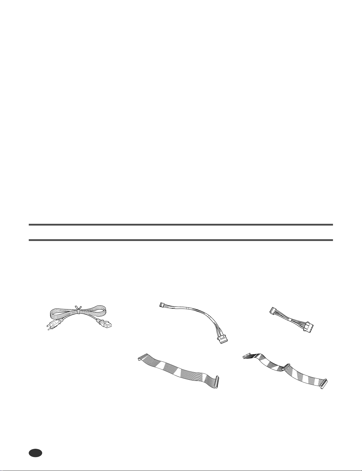
List of Accessories
Your A5000/A4000 package includes the following accessories. Make sure that all of these accessories are included.
• CD-ROM set • Owner’s Manual (this document)................1
• Booklet (“Guide for Accompanying Disks”)............1 • Floppy Disk..................................................4
• Power Cord............................................................1 • Power Cable for ZIP Drive ...........................1
• Power Cable for Internal Hard Disk........................1 • IDE Cable for Internal Hard Disk .................1
• SCSI Cable for Internal Hard Disk.........................1
Power Cord
Power Cable for
Internal Hard Disk (long)
SCSI Cable for
Internal Hard Disk
Power Cable for
ZIP Drive (short)
IDE Cable for
Internal Hard Disk
* If any of the above items is missing, please contact your Yamaha dealer for assistance.
* See the CD-ROM jackets or the separate “Guide for Accompanying Disks” booklet for information about the contents and use of the CD-ROMs
and floppy disks.
Unauthorized copying of copyrighted software for purposes other than purchaser’s personal use is prohibited.
4 A5000/A4000 ● ● ● ● ● ● ● ● ● ● ● ● ● ● ● ● ● ● ● ● ● ● ● ● ● ● ● ● ● ● ● ● ● ● ● ● ● ● ● ● ● ● ● ● ● ● ● ● ● ● ● ● ● ● ● ● ● ● ● ● ● ● ● ● ● ● ● ● ●

Features
Professional Sampler With Endless Potential
The A5000/A4000 pro vides superior sound and peformance for a wide range of applications including
break-beat production and playback, phrase sampling, musical instrument sampling, and much, much
more.
Advanced Built-in Effect System
The A5000 has 6 high-performance effect blocks, and the A4000 has 3. An extensive range of effects
from simple ambience to sophisticated sound modification can be used to enhance or radically alter the
sound of samples, break-beats, or sampled phrases. Effects can even be applied during recording, so
you can create samples with integral effects!
Fast, Efficient Operation
A large 320 x 80 dot full-graphic LCD panel displays sample waveforms, ef fect connections, and other
important data in easy-to-understand form. The panel knobs, mode buttons, and function buttons also
make operation exceptionally easy, intuitive, and versatile, while offering an amazing degree of realtime playback control.
Features
Exceptional Expandability
With a built-in SCSI interf ace and internal SCSI and IDE connectors it’s easy to add internal hard disk
or ZIP drives, or external hard disk, ZIP, CD-R OM, CD-R or other dri v es. Further , 4 SIMM slots allo w
the sample memory to be expanded to maximum 128 megabytes. An optional AIEB1 I/O expansion
board can be installed to provide 6 assignable analog outputs as well as digital coaxial and optical
inputs and outputs.
Compatibility with a Wide Range of Sample Formats
In addition to being able to export and import AIFF and WAV wave files to or from floppy disk, SCSI
disk, CD-ROM or other media, The A5000/A4000 can import a wide range of sample files from other
devices including the Yamaha EX7/5/5R, SU700, and samplers from other manufacturers.
A Wide Selection of Sample Data Included
The A5000/A4000 comes with the CD-ROMs packed with useful sample data and audio sampling
sources. Load the sample data directly, and record the audio source material to create your own samples. You can begin using your A5000/A4000 to make music immediately.
(An external SCSI CD-ROM drive is required to load the sample data.)
* The company names and product names in this Owner’s Manual are the trademarks or registered trademarks of
their respective companies.
● ● ● ● ● ● ● ● ● ● ● ● ● ● ● ● ● ● ● ● ● ● ● ● ● ● ● ● ● ● ● ● ● ● ● ● ● ● ● ● ● ● ● ● ● ● ● ● ● ● ● ● ● ● ● ● ● ● ● ● ● ● ● ● ● ● ● ● A5000/A4000 5
Using the Manual
Using the Manual
Manual Organization
This manual is divided into 10 chapters, as follows:
Chapter 1 (page 17 — 30)
Connecting the A5000/A4000 to external MIDI equipment, amplifiers, etc., and powering up. Please
read this chapter before using your A5000/A4000 for the first time.
Chapter 2 (page 31 — 56)
An easy introduction to sampling and some of the A5000/A4000’s main feature. Follow the “handson” instructions to become familiar with your A5000/A4000.
Chapter 3 (page 57 — 86)
An in-depth look at the A5000/A4000 system and basic operating procedures. Essential kno wledge for
anyone who wants to make full use of the A5000/A4000’s capabilities.
Chapter 4 — Chapter 9 (page 87 — 230)
The “reference” chapters, with complete, detailed information on all of the A5000/A4000 functions
and features.
Appendix (page 231)
Information on installing options, specifications, error messages, MIDI data format, and more.
Finding Information You Need
The manual offers several ways for you to locate specific information.
The Table of Contents (page 8)
Look here to locate information in relatively broad categories.
The Index (page 287)
Function names, key words, and other specific terms are listed in alphabetical order with page numbers allowing you to locate specific information quickly and easily.
Controls & Connectors (page 10)
When you want to know about specific controls or connectors, go to this section.
The A5000/A4000 Function Tree (page 73)
The Function Tree lets you find functions in context within the sampler’s internal organization.
6 A5000/A4000 ● ● ● ● ● ● ● ● ● ● ● ● ● ● ● ● ● ● ● ● ● ● ● ● ● ● ● ● ● ● ● ● ● ● ● ● ● ● ● ● ● ● ● ● ● ● ● ● ● ● ● ● ● ● ● ● ● ● ● ● ● ● ● ● ● ● ● ● ●
Flip Through the Pages
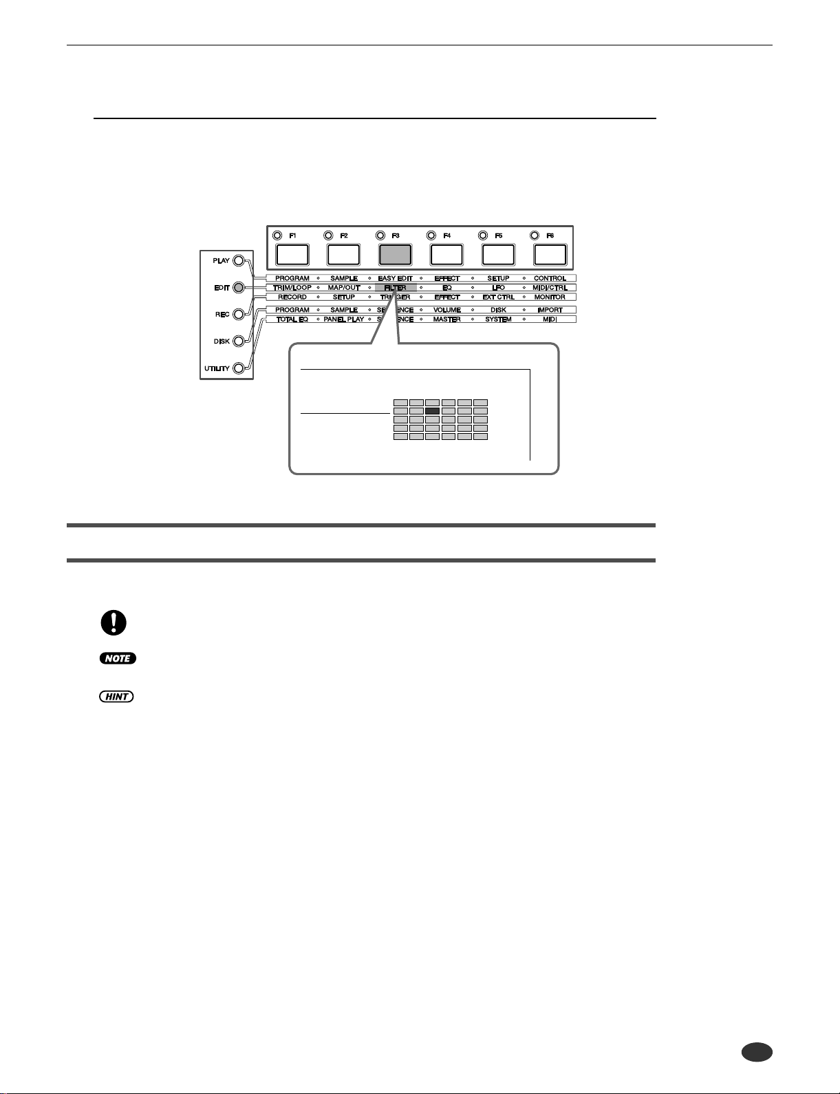
The chapter number and title are printed at the bottom of each manual page. The mode and function
described on each page are listed at the top of the page. Next to the mode and function names at the top
of each page is a 5 x 6 matrix which visually indicates the function described based on the mode and
function button positions as shown below.
Function Buttons
Mode Buttons
EDIT-FILTER
Using the Manual
Other Conventions
The following symbols and conventions are used throughout this manual:
This symbol indicates important information that could, for example, prevent you from
accidentally erasing valuable data.
Additional information that will give you a more complete understanding of the related
function or feature.
Hints on how you might be able to make the most of a feature or function.
(PLAY-PROGRAM-PgmSel), etc.
This type of expression indicates the mode, function, and display page on which a certain function or parameter can be found. The example points to the PLAY mode PROGRAM function group PgmSel display page.
[PLAY], etc. Indicates a panel button — in this case the [PLAY] button.
page ?? Page reference. Directs you to another page for related information.
In general this manual describes operation of both the A5000 and A4000. When a feature or function
described is different or is not available in the A4000, this will be mentioned in the text or in parentheses
following the text.
The illustrations and LCD screens as shown in this owner’s manual are for instructional purposes only, and
may be different from your instrument.
● ● ● ● ● ● ● ● ● ● ● ● ● ● ● ● ● ● ● ● ● ● ● ● ● ● ● ● ● ● ● ● ● ● ● ● ● ● ● ● ● ● ● ● ● ● ● ● ● ● ● ● ● ● ● ● ● ● ● ● ● ● ● ● ● ● ● ● A5000/A4000 7
Contents
Contents
List of Accessories................................................................... 4
Features................................................................................... 5
Using the Manual..................................................................... 6
Manual Organization ............................................................... 6
Finding Information You Need.................................................. 6
Other Conventions................................................................... 7
Panel and Connector Arrangement....................................... 10
A5000/A4000 Options ........................................................... 14
Handling the Floppy Disk Drive(FDD) and Floppy Disk......... 15
Chapter 1 Setting Up
Setup Procedure.................................................................... 18
Power Connection..................................................................19
Audio Output Connections..................................................... 20
Audio Input Connections........................................................ 23
MIDI Connections.................................................................. 25
Powering On and Off............................................................. 27
Sound Check......................................................................... 28
Tutorial
Chapter 2 Sampler Basics & Essential
Procedures
Sampler Basics.............................................................................. 32
Essential Procedures .................................................................... 37
Chapter 3 The A5000/A4000 System & Features
1. System Overview...................................................................... 58
Internal Structure................................................................... 58
Sampling T one Generator...................................................... 59
The Effect Stage....................................................................63
Total EQ................................................................................. 64
Controllers............................................................................. 64
Sequencer............................................................................. 64
I/O Interface...........................................................................65
Data Organization & Management........................................ 65
2. The A5000/A4000 Functions.................................................... 68
A5000/A4000 Mode Organization ......................................... 68
Function T ree.........................................................................73
3. Basic Operation ........................................................................ 77
Common Mode Display Features.......................................... 77
Selecting Modes & Functions................................................ 77
Selecting Display Pages........................................................78
Editing Parameters................................................................ 79
Executing Functions.............................................................. 80
Command Selection.............................................................. 80
Character Entry ..................................................................... 81
MIDI Input.............................................................................. 82
QUICK Entry..........................................................................83
T ree Vie w Display .................................................................. 83
A/D Input................................................................................ 85
MIDI Indicator........................................................................ 85
Shortcut Operation ................................................................ 86
Special Button Functions.......................................................86
Factory Reset........................................................................ 86
Reference
Chapter 4 PLAY Mode
About the PLAY Mode....................................................................88
1. PROGRAM .................................................................................89
Program Select......................................................................89
Program Mix...........................................................................90
Program Portamento..............................................................91
2. SAMPLE..................................................................................... 93
Select Sample........................................................................ 93
Select Sample from Sample Bank.........................................95
3. EASY EDIT................................................................................. 96
Mix ......................................................................................... 96
Output....................................................................................97
Out & Gain.............................................................................97
Filter.......................................................................................98
Pitch.......................................................................................98
Amplitude EG......................................................................... 99
Key......................................................................................... 99
Velocity.................................................................................100
Crossfade.............................................................................100
Control ................................................................................. 101
4. EFFECT.................................................................................... 102
Effect Setup A......................................................................102
Effect Setup B......................................................................104
Effect Edit.............................................................................104
5. SETUP...................................................................................... 107
S/H Speed ...........................................................................107
AD Input...............................................................................107
6. CONTROL ................................................................................110
Program Controller A/B........................................................ 110
Channel Setup.....................................................................112
Program LFO.......................................................................113
Chapter 5 EDIT Mode
About the EDIT Mode................................................................... 118
1. TRIM/LOOP.............................................................................. 120
Waveform.............................................................................120
Sample Information.............................................................. 124
Loop Remix.......................................................................... 125
2. MAP/OUT ................................................................................. 127
Mix & Key Range.................................................................127
Pitch.....................................................................................129
Expand & Velocity Range.....................................................131
Level Scaling........................................................................132
3. FILTER......................................................................................133
Filter & EQ ........................................................................... 133
Filter Scaling........................................................................135
4. EG.............................................................................................137
Amplitude EG....................................................................... 137
Filter EG............................................................................... 138
Pitch EG............................................................................... 140
5. LFO...........................................................................................143
LFO......................................................................................143
8 A5000/A4000 ● ● ● ● ● ● ● ● ● ● ● ● ● ● ● ● ● ● ● ● ● ● ● ● ● ● ● ● ● ● ● ● ● ● ● ● ● ● ● ● ● ● ● ● ● ● ● ● ● ● ● ● ● ● ● ● ● ● ● ● ● ● ● ● ● ● ● ● ●

Contents
6. MIDI/CTRL................................................................................ 145
MIDI Set............................................................................... 145
Sample Controller A & B...................................................... 146
Chapter 6 RECORD Mode
About the RECORD Mode........................................................... 150
1. RECORD .................................................................................. 151
Record................................................................................. 151
2. SETUP...................................................................................... 153
Record Setup....................................................................... 153
Process................................................................................ 157
3. TRIGGER ................................................................................. 158
Trigger.................................................................................. 158
4. EFFECT.................................................................................... 160
Recording Effect Setup........................................................ 160
Recording Effect Edit...........................................................160
5. EXT CTRL (External Control)................................................. 161
CD-DA Control..................................................................... 161
6. MONITOR................................................................................. 163
Monitor & Click..................................................................... 163
Chapter 7 DISK Mode
About the DISK Mode.................................................................. 166
1. PROGRAM............................................................................... 167
PgmLoad............................................................................. 167
2. SAMPLE................................................................................... 169
SmpLoad............................................................................. 169
3. SEQUENCE.............................................................................. 171
SeqLoad.............................................................................. 171
4. VOLUME................................................................................... 172
Volume................................................................................. 172
5. DISK ......................................................................................... 173
Disk Select........................................................................... 173
Disk Setup........................................................................... 173
6. IMPORT.................................................................................... 175
Import .................................................................................. 175
7. DISK COMMANDS................................................................... 177
Selecting a Command......................................................... 177
Command Execution........................................................... 177
SAVE................................................................................... 177
FORMAT.............................................................................. 177
COPY VOLUME................................................................... 181
SYSTEM FILE..................................................................... 182
BACKUP..............................................................................182
CD-DA................................................................................. 184
LOAD OS............................................................................. 185
Chapter 8 UTILITY Mode
About the UTILITY Mode............................................................. 188
1. TOTAL EQ ................................................................................ 189
Total Equalizer..................................................................... 189
2. PANEL PLAY............................................................................ 191
Knob Controller.................................................................... 191
Knob Controller Setup......................................................... 191
Function Key Play Setup...................................................... 192
3. SEQUENCE.............................................................................. 194
Sequence ............................................................................ 194
4. MASTER...................................................................................195
Tuning ..................................................................................195
Output..................................................................................195
5. SYSTEM ...................................................................................197
KeysSet................................................................................197
Customise............................................................................198
6. MIDI .......................................................................................... 200
Channel Message................................................................200
System Exclusive................................................................. 201
Chapter 9 COMMAND
About the COMMANDS................................................................ 204
Selecting a Command .........................................................206
Command Execution............................................................206
COPY................................................................................... 206
DELETE...............................................................................208
SAVE....................................................................................208
ARRANGE...........................................................................211
FREEZE............................................................................... 212
REGISTER ..........................................................................214
BULK DUMP........................................................................216
INITIALIZE...........................................................................217
PROCESS ........................................................................... 218
LOOP DIVIDE......................................................................221
RESAMPLE ......................................................................... 222
STEREO → MONO .............................................................225
MOVE .................................................................................. 226
CREATE OSC......................................................................227
EXPORT..............................................................................228
REVERT .............................................................................. 230
Appendix
Installing Optional Equipment....................................................232
Removing the Top Cover......................................................232
Replacing the Top Cover......................................................233
Installing SIMMs ..................................................................234
Installing the AIEB1 I/O Expansion Board ........................... 237
Installing an Internal SCSI Hard Disk ..................................240
Installing an Internal IDE Hard Disk.....................................244
Installing an ATAPI ZIP Drive ...............................................247
Connecting external SCSI devices ...................................... 251
Specifications............................................................................... 254
Effect Type List.............................................................................256
Effect Parameter List...................................................................258
Control Change Number List......................................................270
Troubleshooting ........................................................................... 271
Error Messages............................................................................273
MIDI Data Format .........................................................................274
MIDI Implementation Chart .........................................................286
Index.............................................................................................. 287
● ● ● ● ● ● ● ● ● ● ● ● ● ● ● ● ● ● ● ● ● ● ● ● ● ● ● ● ● ● ● ● ● ● ● ● ● ● ● ● ● ● ● ● ● ● ● ● ● ● ● ● ● ● ● ● ● ● ● ● ● ● ● ● ● ● ● ● A5000/A4000 9
Panel and Connector Arrangement
q
e r
w y t
u
Panel and Connector Arrangement
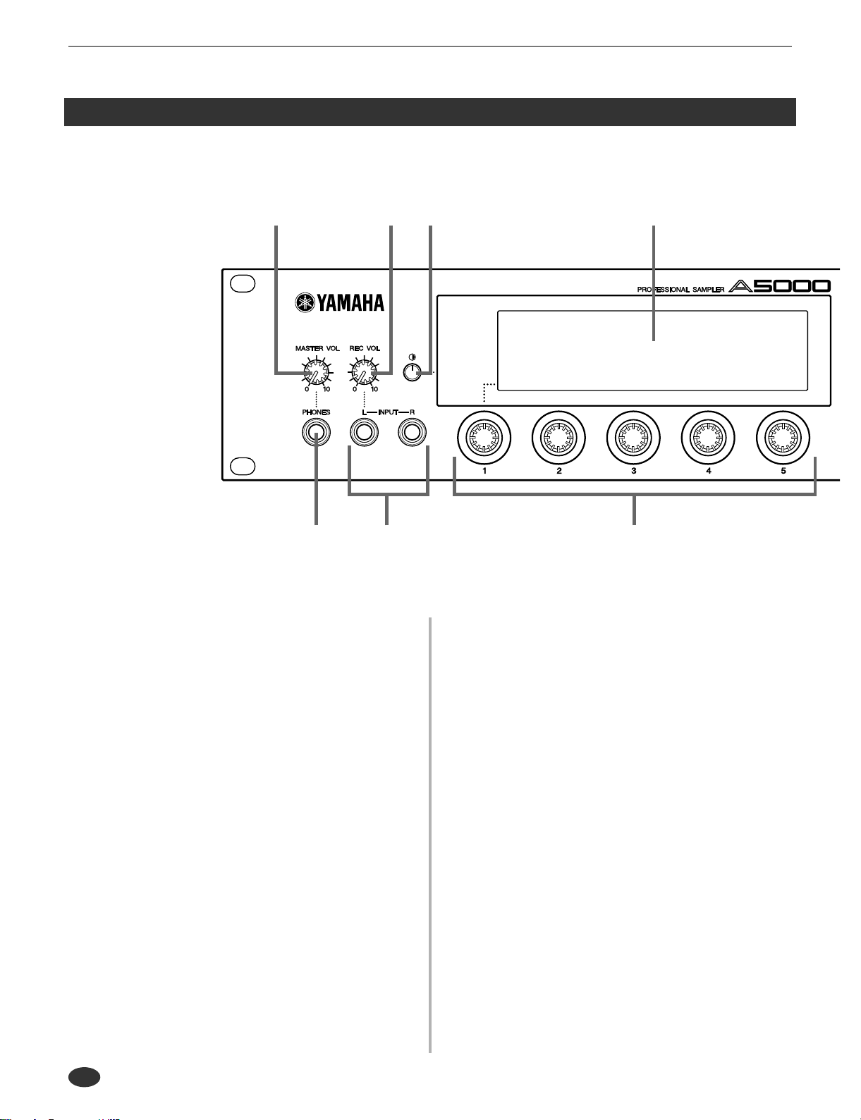
■ Front Panel
q MASTER VOL (Master Volume)
Adjusts the volume of the signal appearing at the STEREO OUT
L/MONO and R jacks as well as the PHONES jack. This control
does not affect output from the ASSIGNABLE OUT L and R
jacks.
This knob does not affect the output level at the ASSIGNABLE
OUT connectors, or at the various connectors provided on the
optional I/O expansion board (AIEB1 board).
w REC VOL (Recording Volume)
Adjusts the input level from the front panel’s INPUT L and
INPUT R jacks. Use the knob to adjust the level when recording
a sample, or when passing an input signal directly through the
A5000/A4000 outputs for realtime output (“A/D In” feature).
This knob does not affect the input level to the DIGITAL IN and
OPTICAL IN connectors on the optional I/O expansion board
(AIEB1 board).
e PHONES jack
Connects to a set of stereo headphones. The PHONES jack
always produces the same signal as the STEREO OUT jacks.
Note that headphone impedance should be between 16 and 150
ohms.
r INPUT L, INPUT R jacks
Use these jacks to input an analog signal for recording, or for
realtime output (“ A/D In” feature). Use the INPUT L jack if you
are supplying a monaural signal.
t Display
The display shows a wide range of information including current
status and available parameters.
y LCD Contrast Control
LCD Contrast Control
Adjusts the contrast of the LCD display panel.
u Knobs
You use the knobs to set the various parameter values, to switch
display pages, and execute operations. In most cases you turn the
knob to set a value, and push the knob to execute an operation —
for example, to start or stop recording. Knobs are numbered 1 to
5.
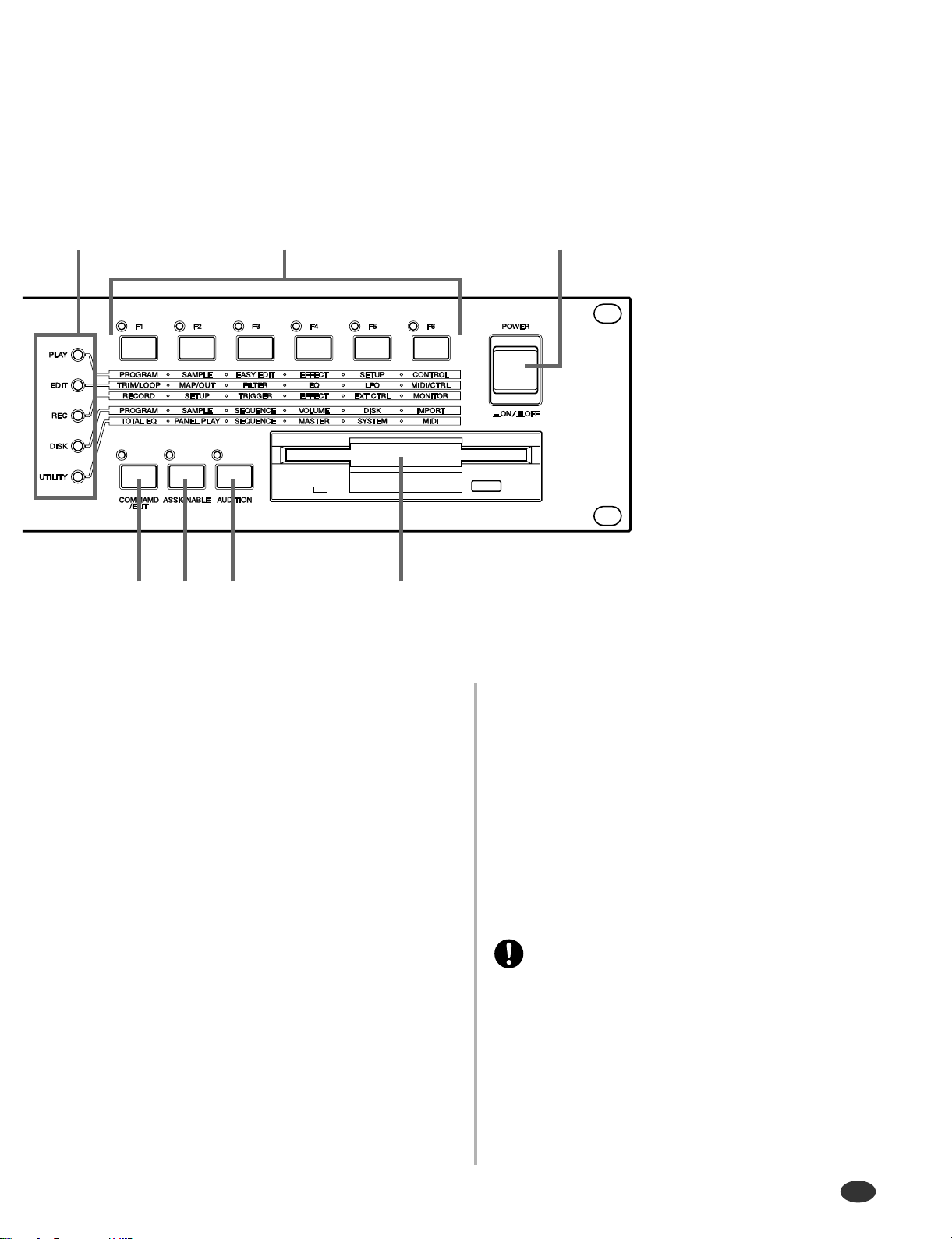
i Mode buttons
The A5000/A4000 provides fiv e operating modes. You select the
mode by pressing the corresponding mode button. The button
lamp comes on to indicate that the mode is selected.
Each mode is further divided into six functions. After selecting
the mode, you can switch among its functions by pressing the
appropriate function keys.
10 A5000/A4000 ● ● ● ● ● ● ● ● ● ● ● ● ● ● ● ● ● ● ● ● ● ● ● ● ● ● ● ● ● ● ● ● ● ● ● ● ● ● ● ● ● ● ● ● ● ● ● ● ● ● ● ● ● ● ● ● ● ● ● ● ● ● ● ● ● ● ● ● ●
i o !4
Panel and Connector Arrangement
!0 !1 !2 !3
(The A5000/A4000 also uses the button lamps to let you know
that it is receiving MIDI data. Each lamp corresponds to a different MIDI data type, and will continue to blink while the A5000/
A4000 is receiving MIDI data of that type. (page 85))
o [F1] — [F6] Function buttons
Use these buttons to switch among the six functions within the
currently selected mode.
!0 [COMMAND/EXIT] button
This button calls the command menu from which you can access
a range of commands not included in the modes. Press a second
time to revert to the mode display. (page 177, 206)
!1 [ASSIGNABLE] button
This button can be used to turn off all notes, reset all controllers,
switch Knobs 2 through 5 for control change operation, switch
the function buttons for tone generator playback, and more.
(page 86)
A5000
!3 Floppy-disk drive
Accepts a 3.5-inch floppy disk. You can use floppy disks to save
and reload your data (programs, samples, sequences, and system
settings).
Note that there is an access lamp at the lower left of the drive.
The lamp lights up while the disk is being accessed. Please do
not eject the floppy-disk while this lamp is on.
To eject a disk, press the EJECT button at the lower right of the
drive. (page 15)
!4 POWER switch
Press once to switch the power on. Press again to turn the power
off. (page 27)
• The A5000/A4000 stores all new data into main memory only, and
will lose all of this data when you switch off the power. You must
therefore be sure to save all important data to disk before turning
the A5000/A4000 off.
!2 [AUDITION] button
Press the button to play out the currently selected sample. You
use this feature to check the sound of the sample while editing.
● ● ● ● ● ● ● ● ● ● ● ● ● ● ● ● ● ● ● ● ● ● ● ● ● ● ● ● ● ● ● ● ● ● ● ● ● ● ● ● ● ● ● ● ● ● ● ● ● ● ● ● ● ● ● ● ● ● ● ● ● ● ● ● ● ● ● ● A5000/A4000 11

Panel and Connector Arrangement
■ Rear Panel
q
q AC inlet
Connects to the AC power cord supplied with the A5000/A4000.
(Please do not use any other power cord with this unit.)
w MIDI IN-A, IN-B, OUT, THRU-A, THRU-B
(MIDI IN, OUT, THRU on the A4000)
These connectors are for connection to external MIDI devices.
The MIDI IN-A and MIDI IN-B connectors (MIDI IN only on
the A4000) are for reception of MIDI messages, while the MIDI
OUT connector is for MIDI transmission. MIDI THRU-A and
THRU-B (MIDI THRU only on the A4000) retransmits the data
received at the MIDI IN connector(s).
e ASSIGNABLE OUT jacks
Analog output jacks. These jacks operate independently of the
STEREO OUT jacks. You can use these jacks to output the
sound of one or more selected samples, or to output the signal
supplied through the front panel’s analog input connectors (page
97, 128). You may also set them so that the y output the same signal as the STEREO OUT jacks (page 125).
t rew
A5000
r STEREO OUT jacks
These are the main analog output jacks.
t SCSI connector
This is a half-pitch 50-pin connector. You use it to connect up a
SCSI hard drive, CD-ROM drive, or other SCSI device.
12 A5000/A4000 ● ● ● ● ● ● ● ● ● ● ● ● ● ● ● ● ● ● ● ● ● ● ● ● ● ● ● ● ● ● ● ● ● ● ● ● ● ● ● ● ● ● ● ● ● ● ● ● ● ● ● ● ● ● ● ● ● ● ● ● ● ● ● ● ● ● ● ● ●
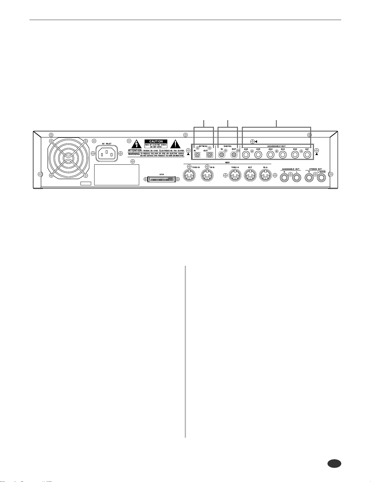
■ Rear Panel (with optional AIEB1 board installed)
Panel and Connector Arrangement
q w e
q OPTICAL IN, OUT connectors
Use these connectors to input or output digital signals over optical-fiber cable. You can use the OPTICAL IN to record a digital
signal of frequency 48kHz, 44.1kHz, or 32kHz. The OPTICAL
OUT connector outputs a digital signal of frequency 44.1kHz.
w DIGITAL IN, OUT connectors
Use these connectors to input or output digital signals over coaxial (RCA-pin) cable. The digital signal format is CD/DAT (S/P
DIF).
You can use the DIGITAL IN connector to record a digital signal
of frequency 48kHz, 44.1kHz, or 32kHz. The DIGITAL OUT
connector outputs a digital signal of frequency 44.1kHz.
e ASSIGNABLE OUT jacks (AS1 to AS6)
Additional analog output jacks. Each pair (1&2, 3&4, 5&6)
operates independently of all other outputs on the A5000/A4000.
You can use these jacks to output the sound of one or more
selected samples, or to output the signal supplied through the
front panel’s analog input connectors (page 97, 128). You may
also set them so that they output the same signal as the STEREO
OUT jacks (page 125).
A5000
● ● ● ● ● ● ● ● ● ● ● ● ● ● ● ● ● ● ● ● ● ● ● ● ● ● ● ● ● ● ● ● ● ● ● ● ● ● ● ● ● ● ● ● ● ● ● ● ● ● ● ● ● ● ● ● ● ● ● ● ● ● ● ● ● ● ● ● A5000/A4000 13
A5000/A4000 Options
A5000/A4000 Options
You can enhance the capability of your A5000/A4000 by installing options. The A5000/A4000 supports
two options: (1) additional memory, and (2) the AIEB1 board (I/O expansion board).
Expansion Memory (SIMMs)
The A5000/A4000 stores all active data in main memory. To play a sample back, you must first load it into
main memory. And whenever you record a sample, you must record it into main memory.
Samples consume a great deal of memory. The A5000/A4000 comes standard with 4 megabytes (4MB) of
memory — but this is only sufficient to store about 48 seconds of high-quality monaural sound (at 44.1kHz
sampling frequency), or approximately 24 seconds of stereo sound.
You can increase this capacity by installing additional memory. The A5000/A4000 accepts expansion memory in the form of SIMMs (single in-line memory modules). Using SIMMs, you can install up to 128MB of
memory onto the A5000/A4000. SIMMs can be purchased from almost any computer-supply dealer.
Adding memory will allow you to record longer samples, and to work with more samples at the same time.
For information about how to install SIMMs, refer to the Appendix. (page 234)
Important Information about Purchase of Expansion SIMMs for the A5000/A4000
The A5000/A4000 does not necessarily support all commercially available SIMMs. Before purchasing SIMMs, please consult your Yamaha dealer or an authorized Yamaha distributor (see
list at end of the Owner’s Manual) for advice. Note that Yamaha cannot assume responsibility
for SIMM malfunctions.
SIMM Type and SIMM Configuration
• You need to use 72-pin SIMMs with access time of 70ns or less. The SIMM module size may be 4MB,
8MB, 16MB, or 32MB. The A5000/A4000 is designed for use with 32-bit (parity non-type) SIMMs, but
can also accept installation of 36-bit (parity-type) SIMMs.
• When purchasing SIMMs, make sure that the SIMM design does not utilize more than 18 memory
chips per module. (SIMMs comprised of more than 18 chips do not operate correctly on the A5000/
A4000.)
• SIMMs must be installed in pairs: you can install either two SIMMs or four SIMMs. Both modules in a
pair must have the same memory capacity.
• The A5000/A4000 ships with 4MB of sampling memory installed, and is capable of accessing up to
128MB. If you add one pair of 32MB SIMMs , f or e xample , y ou increase the av ailab le sampling memory
to a total of (4 + 32 x 2 =) 68MB. If you install four 32MB SIMMs, however, the sampling memory size
becomes 128MB (and the original 4MB are effectively disabled).
• Yamaha recommends that you purchase SIMMs that conform to the JEDEC* standard. Please be
aware, how e v er , that conf ormance to this standard does not constitute a guarantee that the SIMMs will
operate correctly on the A5000/A4000.
* JEDEC (Joint Electron Device Engineering Council) sets standards for terminal configurations within elec-
tronic devices.
The I/O Expansion Board (AIEB1 Board)
In its standard configuration, the A5000/A4000 supports analog I/O only. Although it stores all internal data
in digital form, it does not provide direct digital I/O connectors.
You can add digital I/O capacity by installing an AIEB1 board. The board offers two different digital connector types: optical connectors, and coaxial connectors. As an added benefit, the board also includes three
stereo ASSIGNABLE OUTPUT pairs (six analog jacks), which operate independently of the standard STEREO OUT and ASSIGNABLE OUT jacks.
For information about how to install this board, refer to the Appendix. (page 237)
14 A5000/A4000 ● ● ● ● ● ● ● ● ● ● ● ● ● ● ● ● ● ● ● ● ● ● ● ● ● ● ● ● ● ● ● ● ● ● ● ● ● ● ● ● ● ● ● ● ● ● ● ● ● ● ● ● ● ● ● ● ● ● ● ● ● ● ● ● ● ● ● ● ●
Handling the Floppy Disk Drive(FDD) and Floppy Disk
Handling the Floppy Disk Drive(FDD) and Floppy Disk
Precautions
Be sure to handle floppy disks and treat the disk drive with care. Follow the important precautions below.
Disk Type
The A5000/A4000 disk drive accepts 2HD-type and 2DD-type 3.5" floppy disks.
Inserting/Ejecting Floppy Disks
To insert a floppy disk into the disk drive:
• Hold the disk so that the label of the disk is facing upward and the sliding shutter is facing forw ard,
towards the disk slot. Carefully insert the disk into the slot, slowly pushing it all the w ay in until it
clicks into place and the eject button pops out.
To eject a floppy disk:
• Before ejecting the disk, be sure to confirm that the FDD is stopped (check if the LED below the
floppy disk slot is off).
Press the eject button slowly as far as it will go; the disk will automatically pop out. When the disk
is fully ejected, carefully remove it by hand.
• Never attempt to remove the disk or turn the power off during reading or writing. Doing so can
damage the disk and possibly the disk drive.
• If the eject button is pressed too quickly, or if it is not pressed in as far as it will go, the disk may
not eject properly. The eject button may become stuck in a half-pressed position with the disk
extending from the drive slot by only a few millimeters. If this happens, do not attempt to pull out
the partially ejected disk, since using force in this situation can damage the disk drive mechanism
or the floppy disk. To remove a partially ejected disk, try pressing the eject button once again, or
push the disk back into the slot and then repeat the eject procedure.
• Be sure to remove the floppy disk from the disk drive before turning off the power. A floppy disk
left in the drive for extended periods can easily pick up dust and dirt that can cause data read and
write errors.
● ● ● ● ● ● ● ● ● ● ● ● ● ● ● ● ● ● ● ● ● ● ● ● ● ● ● ● ● ● ● ● ● ● ● ● ● ● ● ● ● ● ● ● ● ● ● ● ● ● ● ● ● ● ● ● ● ● ● ● ● ● ● ● ● ● ● ● A5000/A4000 15
Handling the Floppy Disk Drive(FDD) and Floppy Disk
Cleaning the Disk Drive Read/Write Head
• Clean the read/write head regularly. This instrument employs a precision magnetic read/write head
which, after an extended period of use, will pick up a layer of magnetic particles from the disks
used that will eventually cause read and write errors.
• To maintain the disk drive in optimum working order Yamaha recommends that you use a commercially-available dry-type head cleaning disk to clean the head about once a month. Ask your
Yamaha dealer about the availability of proper head-cleaning disks.
Never insert anything b ut floppy disks into the disk dri v e. Other objects may cause damage to the disk dri v e
or floppy disks.
About the Floppy Disks
To handle floppy disks with care:
• Do not place heavy objects on a disk or bend or apply pressure to the disk in an y way. Alw ays keep
floppy disks in their protective cases when they are not in use.
• Do not expose the disk to direct sunlight, extremely high or low temperatures, or excessive humidity, dust or liquids.
• Do not open the sliding shutter and touch the exposed surface of the floppy disk inside.
• Do not expose the disk to magnetic fields, such as those produced by tele visions, speakers, motors,
etc., since magnetic fields can partially or completely erase data on the disk, rendering it unreadable.
• Never use a floppy disk with a deformed shutter or housing.
• Do not attach anything other than the provided labels to a floppy disk. Also make sure that labels
are attached in the proper location.
To protect your data (Write-protect Tab):
• To prevent accidental erasure of important data, slide the disk’s write-protect tab to the “protect”
position (tab open).
Data backup
• For maximum data security Yamaha recommends that you keep two copies of important data on
separate floppy disks. This gives you a backup if one disk is lost or damaged.
16 A5000/A4000 ● ● ● ● ● ● ● ● ● ● ● ● ● ● ● ● ● ● ● ● ● ● ● ● ● ● ● ● ● ● ● ● ● ● ● ● ● ● ● ● ● ● ● ● ● ● ● ● ● ● ● ● ● ● ● ● ● ● ● ● ● ● ● ● ● ● ● ● ●

Chapter
1
Setting Up
Connecting the A5000/A4000 to external MIDI equipment, amplifiers, etc., and power-
ing up. Please read this chapter before using your A5000/A4000 for the first time.
Setup Procedure...........................................................................18
Power Connection........................................................................19
Audio Output Connections..........................................................20
Audio Input Connections.............................................................23
MIDI Connections .........................................................................25
Powering On and Off....................................................................27
Sound Check.................................................................................28
● ● ● ● ● ● ● ● ● ● ● ● ● ● ● ● ● ● ● ● ● ● ● ● ● ● ● ● ● ● ● ● ● ● ● ● ● ● ● ● ● ● ● ● ● ● ● ● ● ● ● ● ● ● ● A5000/A4000 • Chapter 1 Setting Up 17

Setup Procedure
Setup Procedure
his chapter explains how to set up your equipment and run a simple sound check.
Setup Sequence
This chapter takes you through each of the steps necessary to connect up your system.
Connecting the Power
Explains how to connect up the A5000/A4000’s power cord. (page 19)
Connecting the A5000/A4000 Outputs
Shows how to connect the A5000/A4000’s stereo and assignable outputs to external audio devices.
(page 20)
Connecting the Audio Inputs
Shows how to connect microphones and other input devices to the A5000/A4000. (page 23)
MIDI Connections
Introduces basic MIDI concepts, and shows how to connect up MIDI devices. (page 25)
Power ON/OFF
Explains the proper sequence for turning connected devices on and off. (page 27)
Sound Check
T ak es you through a simple sound check, to confirm that your equipment is connected correctly. (page
28)
• If you have already acquired and intend to install options such as addition SIMM memory, the
optional AIEB1 I/O Expansion Board, internal hard disk or ZIP disk drives, or external SCSI
devices, please install the options before carrying out the setup procedures described in this
chapter.
• SIMM (expansion memory) installation.....page 234
• AIEB1 I/O Expansion Board installation....page 237
• Internal SCSI hard disk installation...........page 240
• Internal IDE hard disk installation.............page 244
• ATAPI ZIP drive installation.......................page 247
• External SCSI device connection..............page 251
18 Chapter 1 Setting Up • A5000/A4000 ● ● ● ● ● ● ● ● ● ● ● ● ● ● ● ● ● ● ● ● ● ● ● ● ● ● ● ● ● ● ● ● ● ● ● ● ● ● ● ● ● ● ● ● ● ● ● ● ● ● ● ● ● ● ● ●
Power Connection
This page shows you how to connect up the power cord that comes with the A5000/A4000.
• Be sure that the A5000/A4000’s power switch is OFF before you attach the cord. (The switch is
OFF when it is all the way out.)
• The A5000/A4000 is designed for use with a grounded line (three-prong outlet).
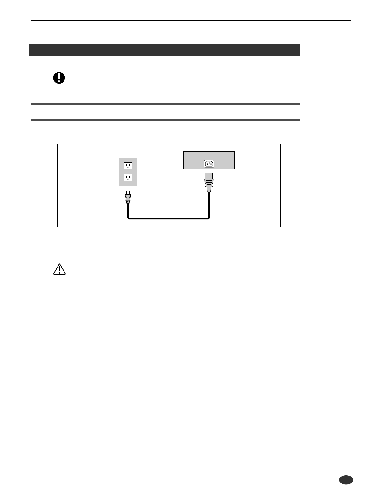
Connecting the Cord
Connect the supplied power cord to the AC inlet on the rear panel. Then plug the other end of the cord into
a 3-prong wall outlet.
Power Connection
Wall Outlet
Power Cord
Rear Panel
AC INLET
WARNING
• Make sure your A5000/A4000 is rated for the AC voltage supplied in the area in which it is to be used (as
listed on the rear panel). Connecting the unit to the wrong AC supply can cause serious damage to the
internal circuitry and may even pose a shock hazard!
• Use only the AC power cord supplied with the A5000/A4000. If the supplied cord is lost or damaged and
needs to be replaced, contact your Yamaha dealer. The use of an inappropriate replacement can pose a fire
and shock hazard!
• The type of AC power cord provided with the A5000/A4000 may be different depending on the country in
which it is purchased (a third prong may be provided for grounding purposes). Improper connection of the
grounding conductor can create the risk of electrical shock. Do NOT modify the plug provided with the
A5000/A4000. If the plug will not fit the outlet, have a proper outlet installed by a qualified electrician. Do
not use a plug adaptor which defeats the grounding conductor.
● ● ● ● ● ● ● ● ● ● ● ● ● ● ● ● ● ● ● ● ● ● ● ● ● ● ● ● ● ● ● ● ● ● ● ● ● ● ● ● ● ● ● ● ● ● ● ● ● ● ● ● ● ● ● A5000/A4000 • Chapter 1 Setting Up 19

Audio Output Connections
Audio Output Connections
This section explains how to connect the A5000/A4000 audio outputs to external devices.
• Be sure that power to the A5000/A4000 and to peripheral devices is OFF before making these
connections. Connecting devices while power is ON may result in damage to amps or speakers.
• Digital I/O connections are available only if the optional AIEB1 board is installed.
Connecting the Analog Outputs
The A5000/A4000 comes standard with the following stereo output jacks.
• STEREO OUT ...............Main analog output.
• ASSIGNABLE OUT.......You can set the jacks to operate independently of the STEREO OUT jacks, so
that they output selected samples or programs only. The feature is useful, for
example, when you want to send the main signal to one audio device while
sending a specific sample to a different device. But it is also possible to set these
jacks so that they output the same signal as the STEREO OUT jacks. (page
195)
If you have installed the optional I/O expansion board (AIEB1 board), your A5000/A4000 will include
three additional ASSIGNABLE OUT pairs (ASSIGNABLE OUT jacks 1 to 6).
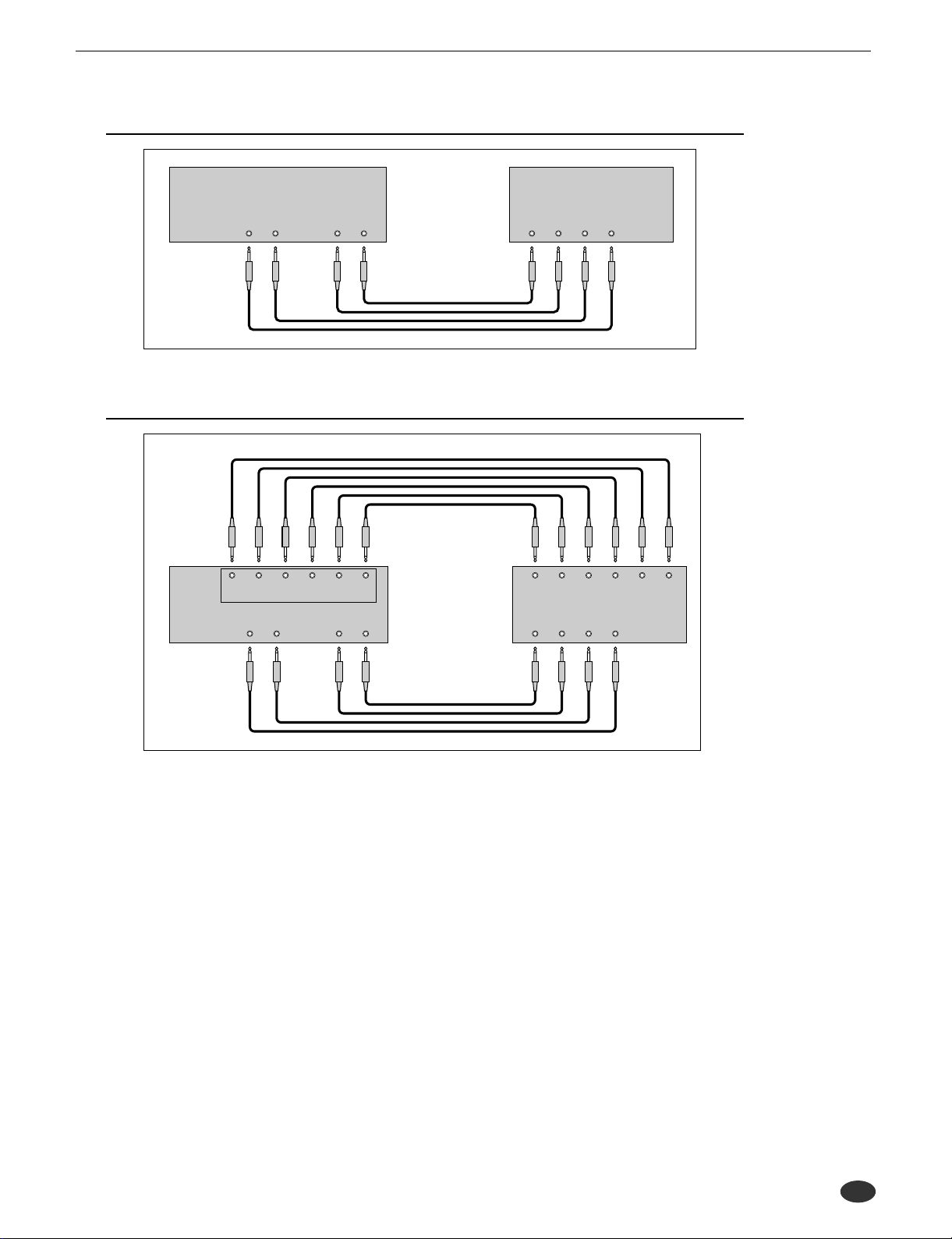
For monaural output:
A5000/A4000 Rear Panel Amp, mixer, etc.
ASSIGNABLE OUT
RL
For stereo output:
A5000/A4000 Rear Panel Amp, mixer, etc.
ASSIGNABLE OUT
RL
STEREO OUT
R L/MONO
STEREO OUT
R L/MONO
INPUT
L
INPUT
R
20 Chapter 1 Setting Up • A5000/A4000 ● ● ● ● ● ● ● ● ● ● ● ● ● ● ● ● ● ● ● ● ● ● ● ● ● ● ● ● ● ● ● ● ● ● ● ● ● ● ● ● ● ● ● ● ● ● ● ● ● ● ● ● ● ● ● ●
For assignable output:
A5000/A4000 Rear Panel Amp, mixer, etc.
Audio Output Connections
ASSIGNABLE OUT
RL
STEREO OUT
R L/MONO
Assignable output using AIEB1 expansion board:
A5000/A4000
Rear Panel
ASSIGNABLE OUT
ASSIGNABLE OUT
RL
123456
STEREO OUT
R L/MONO
Amp, mixer, etc.
INPUT 1
L
LRLRLR
INPUT 3 INPUT 4 INPUT 5
INPUT 1
L
R L
R L
INPUT 2
INPUT 2
R
R
(It is not necessary, of course, to connect up all of the outputs on the expansion board. Connect only
the outputs you need to use.)
● ● ● ● ● ● ● ● ● ● ● ● ● ● ● ● ● ● ● ● ● ● ● ● ● ● ● ● ● ● ● ● ● ● ● ● ● ● ● ● ● ● ● ● ● ● ● ● ● ● ● ● ● ● ● A5000/A4000 • Chapter 1 Setting Up 21
Audio Output Connections
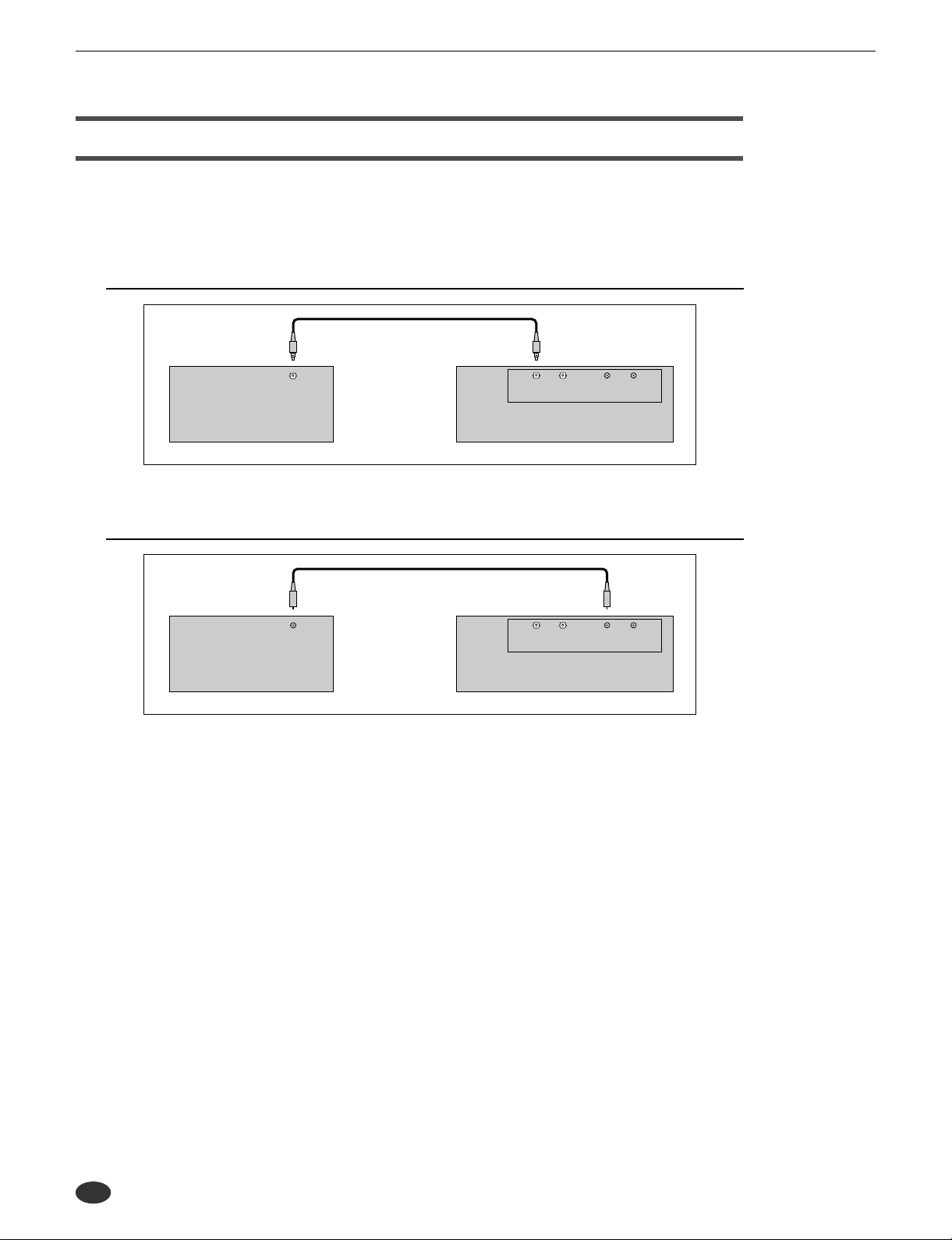
Connecting the Digital Outputs
You can add digital I/O capacity to the A5000/A4000 by installing the optional I/O expansion board
(AIEB1 board). The board enables direct digital output of A5000/A4000 playback and digital through-put.
For purposes of compatibility, the AIEB1 board includes two different output types: OPTICAL OUT (optical fiber) and DIGITAL OUT (coaxial cable). Note that both of these outputs always produce identical signals.
The digital outputs function as assignable outputs. You can set them to output selected samples or programs, or you can set them to produce the same output as the STEREO OUT jacks (by setting the Stereo
Out to Assignable Out parameter to DIG&OPT (UTILITY-MASTER-Out put) : page 195).
• The OPTICAL connectors are protected by plastic covers. You must remove the cover before connecting the cable. Please remember to replace the cover when you disconnect the cable.
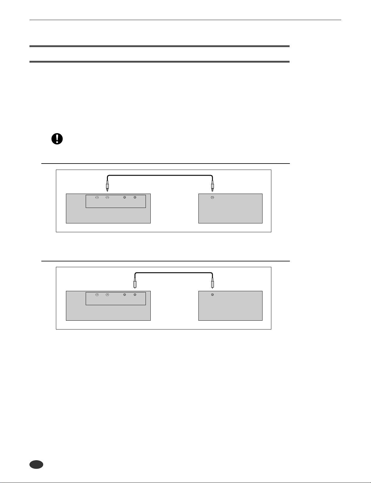
OPTICAL output connection
A5000/A4000 Rear Panel
Coaxial output connection
A5000/A4000 Rear Panel
OUT
INOUTIN
DIGITALOPTICAL
OUT
INOUTIN
DIGITALOPTICAL
OPTICAL INPUT
Digital device
DIGITAL INPUT
Digital device
22 Chapter 1 Setting Up • A5000/A4000 ● ● ● ● ● ● ● ● ● ● ● ● ● ● ● ● ● ● ● ● ● ● ● ● ● ● ● ● ● ● ● ● ● ● ● ● ● ● ● ● ● ● ● ● ● ● ● ● ● ● ● ● ● ● ● ●
Audio Input Connections
This section explains how to connect the A5000/A4000 to a microphone, cassette recorder, or other sound
source.
• Be sure that power to the A5000/A4000 and to peripheral devices is OFF before making these
connections. Connecting devices while power is ON may result in damage to amps or speakers.
• Digital I/O connections are available only if the optional AIEB1 board is installed.
• To select the input to be used for recording, use the Input parameter on the RecData page (page
155).
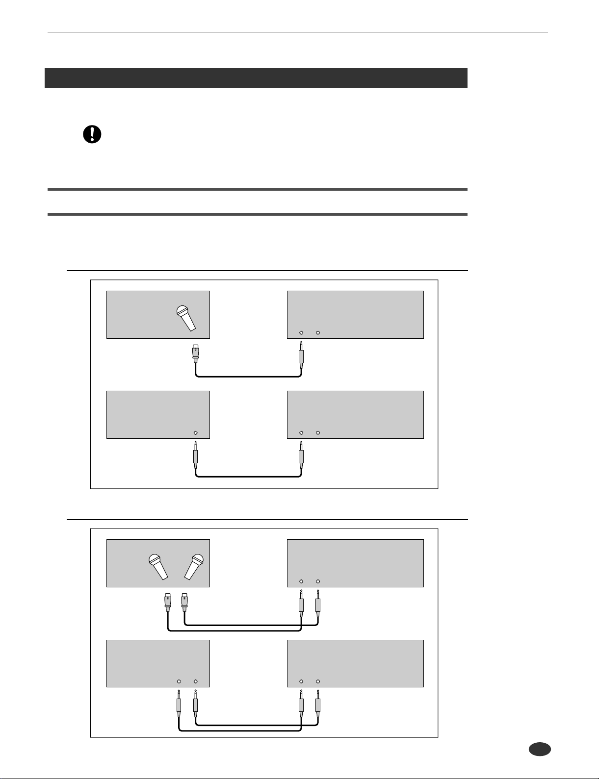
Connecting to Analog Input
The following illustrations show how to connect to an analog input source, such as a microphone, analog
tape recorder, or analog synthesizer.
For monaural input
Audio Input Connections
Microphone, etc.
For stereo input
OUTPUT
A5000/A4000 Front Panel
INPUT
LR
Connect to INPUT L
A5000/A4000 Front PanelTape, recorder, synth, etc.
INPUT
LR
Connect to INPUT L
A5000/A4000 Front PanelMicrophone, etc.
INPUT
LR
A5000/A4000 Front PanelTape, recorder, synth, etc.
OUTPUT
LR
● ● ● ● ● ● ● ● ● ● ● ● ● ● ● ● ● ● ● ● ● ● ● ● ● ● ● ● ● ● ● ● ● ● ● ● ● ● ● ● ● ● ● ● ● ● ● ● ● ● ● ● ● ● ● A5000/A4000 • Chapter 1 Setting Up 23
INPUT
LR
Audio Input Connections
Connecting to Digital Input
Installation of the optional I/O expansion board (AIEB1 board) lets you record digital signals directly from
a digital input source — such as a CD player or DAT recorder.
For purposes of compatibility, the AIEB1 board includes two different input types: OPTICAL (optical
fiber) and DIGITAL (coaxial cable).
OPTICAL input connection
OUT
OPTICAL OUTPUT
A5000/A4000 Rear PanelDigital device
INOUTIN
DIGITALOPTICAL
Coaxial input connection
DIGITAL OUTPUT
OUT
INOUTIN
DIGITALOPTICAL
A5000/A4000 Rear PanelDigital device
24 Chapter 1 Setting Up • A5000/A4000 ● ● ● ● ● ● ● ● ● ● ● ● ● ● ● ● ● ● ● ● ● ● ● ● ● ● ● ● ● ● ● ● ● ● ● ● ● ● ● ● ● ● ● ● ● ● ● ● ● ● ● ● ● ● ● ●
MIDI Connections
This section explains how to connect the A5000/A4000 to MIDI devices.
• Be sure that power to the A5000/A4000 and to peripheral devices is OFF before making MIDI connections. Connecting devices while power is ON may result in MIDI processing errors or unexpected and continuous sound output.
About MIDI
The following overview introduces some basic MIDI concepts. Readers familiar with MIDI may wish to
skip to “MIDI Connection Configurations,” on the next page.
What is MIDI?
MIDI (for “Musical Instrument Digital Interface”) is a standard, internationally-recognized interface
for music-related digital communication among electronic instruments, computers, sequencers, and
related devices.
MIDI connectors and cables
MIDI devices provide MIDI connectors marked IN, OUT, and THRU. The IN connector receives data
from external devices, the OUT connector outputs locally produced data, and the THRU connector
relays data received at the IN connector. MIDI connections are made by running standard MIDI cables
between connectors on different devices. Each MIDI cable connects the OUT or THRU connector of
one device to the IN connector of another device.
MIDI Connections
Channels
A single MIDI cable carries up to 16 channels of performance data. If you have a MIDI setup consisting of three keyboards outputting performance data to a fourth device, for example, each keyboard
would be transmitting data over a different channel. Each channel is identified by its channel number
(1 to 16).
Data types
Each channel can carry a variety of data types. Data types include the following.
Note data: Keys (on keyboard), and key striking force
Control change: Controller movement (modulation wheel, foot controller, etc.)
Program change: Change in voice or program
Aftertouch: Pressure applied to key after initial strike
Pitchbend: Movement of the pitchbend wheel
Bulk data: Voice and device settings and related data
● ● ● ● ● ● ● ● ● ● ● ● ● ● ● ● ● ● ● ● ● ● ● ● ● ● ● ● ● ● ● ● ● ● ● ● ● ● ● ● ● ● ● ● ● ● ● ● ● ● ● ● ● ● ● A5000/A4000 • Chapter 1 Setting Up 25
MIDI Connections
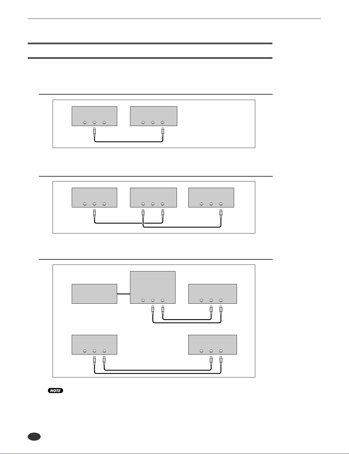
MIDI Connection Configurations
You can use MIDI connections to control the A5000/A4000 from an external keyboard, sequencer, or computer, or to transfer A5000/A4000 data to an external MIDI device.
Connecting to keyboard or MIDI controller
Keyboard (or controller)
MIDI
THRU OUT IN
A5000/A4000 Rear Panel
MIDI
THRU OUT IN
Connecting to keyboard/controller and external tone generator
Keyboard (or controller)
MIDI
THRU OUT IN
A5000/A4000 Rear Panel
MIDI
THRU OUT IN
Tone Generator (synthesizer, etc.)
MIDI
THRU OUT IN
Connecting to computer or sequencer
MIDI Interface
(or tone generator
Computer
with built-in interface)
MIDI
THRU OUT IN
A5000/A4000 Rear Panel
MIDI
THRU OUT IN
Sequencer
THRU OUT IN
MIDI
A5000/A4000 Rear Panel
MIDI
THRU OUT IN
• A wide variety of MIDI connection configurations are available. Design your setup to suit your
device and performance requirements.
• The A5000 has MIDI THRU-A and MIDI THRU-B connectors. The MIDI THRU-A connector
retransmits MIDI data received via the MIDI IN-A connector, and the MIDI THRU-B connector
retransmits MIDI data received via the MIDI IN-B connector.
26 Chapter 1 Setting Up • A5000/A4000 ● ● ● ● ● ● ● ● ● ● ● ● ● ● ● ● ● ● ● ● ● ● ● ● ● ● ● ● ● ● ● ● ● ● ● ● ● ● ● ● ● ● ● ● ● ● ● ● ● ● ● ● ● ● ● ●
Powering On and Off
This section explains the correct procedures for powering up and powering down your equipment.
Power ON
• Speakers or amplifiers should be switched on last to protect against unexpected sound surges
that may damage your equipment.
[Procedure]
1.Switch on power to external MIDI and SCSI devices.
• When powering up MIDI devices, it is generally good practice (although not strictly necessary) to switch
on the transmitting-side device first.
• If you are switching on a SCSI disk or CD-ROM drive, allow the drive a few seconds to get up to speed
before proceeding to Step 2.
2.Switch on the power to the A5000/A4000. (Press the PO WER s witch on the front panel.)
3.Switch on power to speakers and other audio devices.
Powering On and Off
Power OFF
• Like other samplers, the A5000/A4000 stores all new data into main memory only, and will lose all
of this data when you switch off the power. You must therefore save all important data to disk
before turning the A5000/A4000 off.
• Speakers or amplifiers should be switched off first to protect against unexpected sound surges
that may damage your equipment.
[Procedure]
1.Switch off the amplifiers or speakers.
2.Switch off the power to the A5000/A4000. (Press the PO WER s witch on the front panel.)
3.Switch off external MIDI and SCSI devices.
● ● ● ● ● ● ● ● ● ● ● ● ● ● ● ● ● ● ● ● ● ● ● ● ● ● ● ● ● ● ● ● ● ● ● ● ● ● ● ● ● ● ● ● ● ● ● ● ● ● ● ● ● ● ● A5000/A4000 • Chapter 1 Setting Up 27
Sound Check
Sound Check
The next procedure takes you though a simple sound check that you can use to confirm proper connection
of external audio and MIDI devices. The procedure assumes that you are using a MIDI k e yboard to control
A5000/A4000 playback.
[Procedure]
1.Make sure that the A5000/A4000 STEREO OUT jacks are connected to an amplifier or
mixer and that all components are ready for playback. (page 20)
2.Connect the MIDI OUT connector of your MIDI controller — keyboard, sequencer, etc.
— to the MIDI IN-A connector (MIDI IN on the A4000) of the sampler and ensure that all
components are ready for MIDI control. (page 25)
3.Turn on the A5000/A40000 and all connected equipment. (page 27)
4.Set the A5000/A4000 MASTER VOL control to about the center of its range.
5.Set the amplifier, mixer, or other audio reproduction device’s volume to an appropriate
level.
6.Set the external MIDI controller’s MIDI transmit channel to 1.
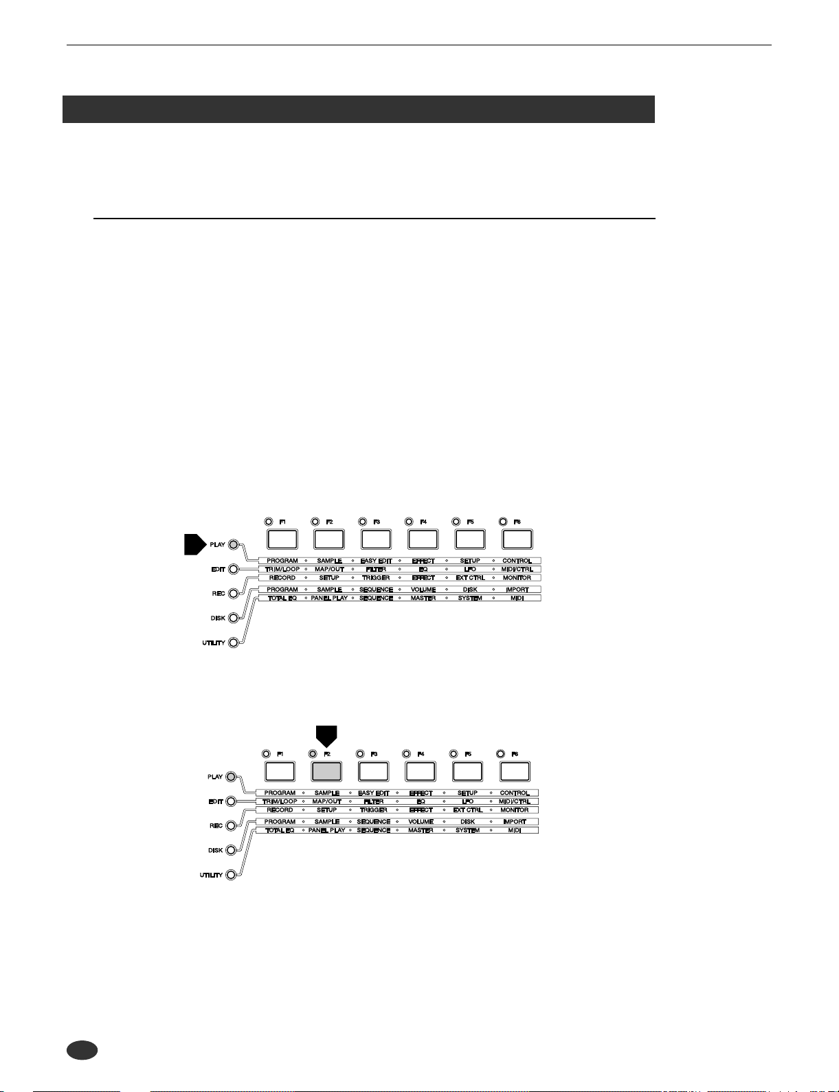
7.Make sure the sampler’s [PLAY] mode button is lit (press the [PLAY] button if it isn’t).
8.Press the [F2] function button.
28 Chapter 1 Setting Up • A5000/A4000 ● ● ● ● ● ● ● ● ● ● ● ● ● ● ● ● ● ● ● ● ● ● ● ● ● ● ● ● ● ● ● ● ● ● ● ● ● ● ● ● ● ● ● ● ● ● ● ● ● ● ● ● ● ● ● ●
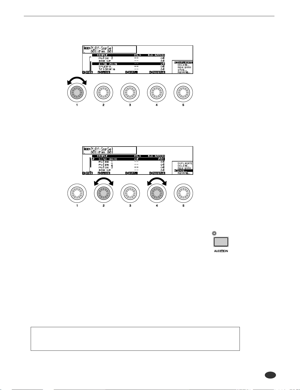
9.Rotate Knob 1 to select the Sample Select (PLAY-SAMPLE-SmpSel) display.
10.Rotate Knob 2 to highlight “sine wave,” and rotate Knob 4 to set the Receive Channel
Assign parameter to “A01” (“01” on the A4000).
• When the A5000/A4000 is turned on a number of basic-waveform samples are automatically created. In
this case we have selected the “sine wave” sample for our sound check.
Sound Check
11.Play the MIDI keyboard or other controller connected to the A5000/A4000.
• If you hear the sine wave sample at this point, all is OK.
• If no sound is produced, try pressing the front-panel [AUDITION] button. If pressing
the [AUDITION] button produces sound it is likely that you have not made the right
MIDI connectors or properly set your MIDI controller. If pressing the [AUDITION]
button produces no sound you should recheck your audio output connections and audio
gear. Turn the power off and go back to the previous section to check you connections
and settings.
• If the sound check is successful, continue with the following steps.
12.Turn down all audio volume controls.
13.Turn the A5000/A4000 MASTER VOL all the way to the left (minimum volume).
14.Turn off the power to the A5000/A4000 and all connected equipment.
• This completes the sound check procedure.
That completes the initial setup and test procedures. In Chapter 2 we’ll provide an easy introduction to sampling and some of the A5000/A4000’s main feature. Follow the “hands-on”
instructions to become familiar with recording and playing samples with your A5000/A4000.
● ● ● ● ● ● ● ● ● ● ● ● ● ● ● ● ● ● ● ● ● ● ● ● ● ● ● ● ● ● ● ● ● ● ● ● ● ● ● ● ● ● ● ● ● ● ● ● ● ● ● ● ● ● ● A5000/A4000 • Chapter 1 Setting Up 29

Sound Check
30 Chapter 1 Setting Up • A5000/A4000 ● ● ● ● ● ● ● ● ● ● ● ● ● ● ● ● ● ● ● ● ● ● ● ● ● ● ● ● ● ● ● ● ● ● ● ● ● ● ● ● ● ● ● ● ● ● ● ● ● ● ● ● ● ● ● ●
 Loading...