

Yaesu FTM-400DDE, FTM-400DR Operating Manual
Before Using
Installation and Connection
Basic Operations
Using the Memory
Scanning
Using the GPS Function
Using the APRS Function
Using the GM Function
Convenient Functions
Functions to be used
when Necessary
Customize Menu Settings
and User Preferences
Appendix
144/430MHz 50W
DUAL BAND TRANSCEIVER
C4FM FDMA/FM
Operating Manual
2
Before Using
Introduction
Features of this radio
144/430 MHz dual band mobile radio equipped with standard C4FM digital
communication modem
Clear audio and data communication is achieved using the digital modem functions
Wide band receive in the 108 MHz to 999 MHz range
(wireless business, public service and air band)
Transmit power 50 watts with cooling fan
Full color 3.5-inch LCD, high luminance TFT touch panel controller
Intuitive, user touch panel operation
500 memory channels in the Band A (band at the top of the display) and 500
channels in the Band B (band at the bottom of the display)
The frequency and settings memories can be saved, using a micro-SD card. The
data in the micro-SD card can easily be copied to other radios
Diverse range of scanning functions (VFO scan, memory scan etc.)
Built-in GPS receiver unit, location and movement information can be displayed and
GPS data can be output to connected devices
Incorporated APRS® functions. Position, movement data and messages can be
communicated to other stations, digipeaters and the Internet.
*Refer to the separate “APRS Operating Manual”
GM (Group Monitor) function where in a group of frequently communicating members
can be registered, and then position information and messages can be exchanged
*Refer to the separate “GM Operating Manual”
Supports Yaesu WIRES-X Internet linking, providing communication with remote
partners using the Internet
*Refer to the separate “WIRES-X Operating Manual”
Bluetooth adaptor unit BU-2 (sold separately) permits hands-free operation
Voice guide unit FVS-2 (sold separately) provides frequency voice announcement,
and recording of received audio
Camera-equipped microphone MH-85A11U (sold separately). Images taken with the
camera can be transmitted to other stations, and also shown on the LCD display.
* The APRS, GM and WIRES-X Operating Manuals are not included with the product.
Please download them from the Yaesu website.
3
Before Using
Introduction
Important precautions for mobile radio operation
The use of protective tape or covering is recommended to protect the wiring and the
power cord inside the vehicle.
When installing the unit inside a vehicle, locate the radio, antenna, co-axial cable,
etc. at least 20 cm away from the following control equipment.
Install the antenna and co-axial cable away from the control unit and wiring harness.
Place all cables so they do not entangle and impede the driver or passengers. Never
place any equipment in a location where it may pose a danger to the passengers,
where it may interfere with driving, or obstruct the driver field of view.
Do not install any apparatus in such a way that it may interfere with the proper
operation of the air bags.
After installing the radio, check that the brake lamp, head lamp, turning indicator
lights, wiper, etc. are working normally with the radio power switched on.
Keep full attention on driving, do not operate the radio controls or look at the radio
display while driving. Stop the vehicle at a safe location, before operating the radio
controls or looking at the display.
Do not drive the car in such a way that external sounds required for safe driving
cannot be heard. Most areas and districts prohibit the use of earphones and
headphones while driving.
When using the radio transmitter, if it appears to have abnormal effects on the control
equipment of the vehicle, stop the engine, turn off the power supply, and disconnect
the power cord. Resolve the problem before continuing to operate the radio
equipment.
When using the radio in an electric or hybrid car, the receiver may experience high
RF interference and noise from the inverters that are built into the electric vehicle.
4
Before Using
Introduction
touch panel
The touch panel of the controller is designed to work with the slightest touch of a finger.
The touch panel may not work when a protective film or sheet is adhered to the LCD.
Use of a pointed fingernail or pen to operate the touch panel, or pressing too hard
may damage or scratch the screen.
Smart phone operations such as flicking, pinch in and pinch out are not possible.
To clean the touch panel, switch off the power supply first before using a dry, soft
cloth to wipe away dust and dirt from the touch panel.
When the touch panel is really dirty, wet a soft cloth and wring it out thoroughly
before using it to wipe the touch panel.
When wiping the touch panel, be careful not to wipe too hard or scratch the surface
with your nails.
When the touch panel is scratched, it may become difficult to see the display.
APRS is a registered trademark of Mr. Bob Bruninga of WB4APR.
SmartBeaconing is supplied by HamHUD Nichetronix.
Microsoft, Windows and Windows Vista are registered trademarks of Microsoft
Corporation in the United States and other countries.
Other company and product names listed in this manual are trademarks and registered
trademarks of their respective companies.
Unauthorized reproduction or copying of a part or all of the copyrights owned by Yaesu
Musen Co., Ltd. in any form whatsoever is strictly prohibited.
5
Before Using
Introduction
How to read this manual
In this manual, controller operations are expressed as follows:
Press ............................................Indicates that the key or switch is to be pressed
quickly.
Press for 1 second or longer .........Indicates that the key or switch is to be pressed
for one second or longer.
Touch .......................................Indicates that the symbol on the touch panel
screen is to be touched quickly.
Touch for 1 second or longer ...Indicates that the symbol on the touch panel
screen is to be touched for one second or longer.
Select ...................................Indicates that the items are to be highlighted on
the touch panel screen.
The following symbols are also used in this manual:
...Explains information to avoid incorrect operation.
...Explains operating hints and helpful advice.
Also note: the actual product may differ from the drawings shown in this manual.
6
Before Using
Introduction ................................................................. 2
Features of this radio ............................................. 2
Important precautions for mobile radio operation .. 3
About the touch panel ............................................ 4
About registered trademarks and copyrights ......... 4
How to read this manual ........................................ 5
............................................................. 9
Safety Precautions (make sure to read these) ........... 9
Accessories .............................................................. 13
Name and Function of Each Component ................. 14
Controller ............................................................. 14
Front ................................................................ 14
Back ................................................................ 15
Left side ........................................................... 15
Main body ............................................................ 16
Front ................................................................ 16
Back ................................................................ 16
Microphone (MH-48A6JA) ................................... 17
Explanation of the screen .................................... 18
..................................
Installing the Radio ................................................... 24
Precautions during installation ............................. 24
Installation location when used in a
mobile unit ......... 24
About the antenna................................................ 25
Install the antenna ........................................... 25
Installing the main body ....................................... 27
Installing the controller ......................................... 28
Connecting the Radio ............................................... 29
Connecting the controller to the main body ......... 29
Connecting the microphone ................................. 29
Connecting the antenna ....................................... 29
Connecting the Power Supply .................................. 30
Connecting the car battery .............................. 30
Connecting the external
power supply equipment ......... 32
Setting Up the micro-SD Card .................................. 33
Micro-SD cards that can be used......................... 33
Things to note when using micro-SD cards ......... 33
Installing the micro-SD card ................................. 34
Removing the micro-SD card .......................... 34
Initializing the micro-SD card ............................... 35
.................................................... 36
Receiving .................................................................. 36
Turning the power on ........................................... 36
Switching the power off ................................... 36
Inputing the call sign ............................................ 37
Switching the operating band............................... 38
Adjusting the volume............................................ 38
Adjusting the squelch level .................................. 39
Tuning the radio ................................................... 40
Changing the frequency steps ........................ 41
Switching the operating mode.............................. 44
Switching the communication mode .................... 45
Switching the modulation mode ........................... 46
Displaying the band scope ................................... 47
Muting the audio .................................................. 48
Communicating......................................................... 49
Transmitting ......................................................... 49
Adjusting the transmit power ........................... 50
Adjusting the sensitivity of the microphone ..... 50
Communicating in the FM mode .......................... 51
Communicating using the repeater ...................... 52
Other Settings........................................................... 54
Changing the beep volume .................................. 54
Locking the knobs and switches .......................... 55
Adjusting the date and time ................................. 56
Adjusting the display brightness .......................... 58
Changing the background color of the
frequency display area ........ 60
Reconfiguring the Settings ....................................... 61
.................................................. 62
Writing to the memory .......................................... 62
Recalling the memory .......................................... 63
Recalling the home channel................................. 63
Changing the frequency of the home channel ... 64
Erasing the memory ............................................. 65
Naming the memory............................................. 66
Changing the method of the
memory tag display ....... 67
Split memory ........................................................ 68
Receiving Weather Broadcast Channels
(USA version only) ....... 70
Assigning the “WX” function to a
programmable key on the microphone ....... 71
Recalling the weather channels ...................... 71
Listening the weather alert .............................. 71
................................................................. 72
Signal Search ........................................................... 72
VFO scan ............................................................. 72
Setting the receive operation when the
scanning stops .... 73
Memory scan ....................................................... 74
Selecting the scanning method ....................... 75
Setting the specified memories ....................... 75
Scan only the specified memory channels ...... 76
Setting the memories to be skipped ................ 77
Scanning the programmable memories (PMS) .... 79
Writing into the programmable memory .......... 79
Scanning the programmable memory ............. 80
Monitoring the Home Channel .................................. 81
Using the dual receive ..................................... 81
Setting the restart condition of dual receive .... 82
........................................ 83
What is GPS? ........................................................... 83
Positioning Using GPS ............................................. 83
Positioning using an external GPS device ...... 84
Checking the satellite capture status .............. 86
Displaying the position information ...................... 87
7
Before Using
Displaying the current position
information of your station ........ 87
Displaying the position information
of the partner station in the digital mode ...... 87
Explanation of the position information
screen ...... 88
Recording the position information
(GPS log function)....... 89
Checking the route using a
personal computer ...... 90
Measuring the altitude.......................................... 90
Other settings....................................................... 92
Using the Smart Navigation Function ....................... 93
Displaying the Compass screen ...................... 93
Using the real-time navigation function ................ 94
Using the backtrack function ................................ 95
Saving the destination ..................................... 95
Displaying the position of the
destination in real time ..... 97
...................................... 98
What is the APRS Function? .................................... 98
.......................................... 99
What is the GM Function? ........................................ 99
Basic Methods to use the GM function ................... 100
.......................................... 102
Communicating with Specified Partner Stations..... 102
Using the tone squelch ...................................... 102
Setting the tone frequency ............................ 102
Using the tone squelch .................................. 103
Transmitting the tone signal .......................... 103
Using digital code squelch ................................. 104
Setting the DCS code .................................... 104
Using DCS .................................................... 105
Using the pager function .................................... 106
Setting the receive station code .................... 106
Activating the pager function ......................... 108
Recalling a specified station .......................... 108
Notification of an incoming call from a
partner station using the bell ......110
Other squelch functions ......................................110
Using the DTMF Function........................................112
Registering the DTMF code ...........................112
Transmitting the registered DTMF code .........113
Sending out the DTMF code manually ...........114
Using the Timer Function.........................................115
Using the stopwatch function ..............................115
Displaying the timer / clock screen .................115
Using the lap timer .........................................116
Using the countdown timer .............................117
Using the APO function .......................................119
Using the TOT function ...................................... 120
Changing the Touch Key Function .......................... 121
Sending and Receiving Messages and Pictures .... 122
Viewing messages and pictures .................... 122
Sorting the messages and pictures ............... 123
Downloading messages and images ................. 124
Sending messages and pictures ........................ 125
Creating and sending a message ................. 125
Sending saved pictures ................................. 129
Replying to a message or picture .................. 130
Forwarding messages and pictures .............. 132
..............
Using the Bluetooth Headset .................................. 134
Mounting the Bluetooth unit “BU-2”.................... 134
Setting the Bluetooth headset operation ............ 136
Identifying the Bluetooth headset ...................... 137
Using the Bluetooth headset .............................. 139
Taking Pictures with the optional Camera
(Snapshot Function) ..... 140
Connecting the speaker microphone
with camera...... 140
Taking pictures ................................................... 141
Viewing a saved picture ..................................... 143
Optional receive Audio Record and Playback ........ 144
Mounting the voice guide unit “FVS-2”............... 144
Using the voice memory .................................... 146
Setting the voice memory operation .............. 146
Recording the receive audio ......................... 147
Replaying the recorded audio ....................... 147
Erasing the recorded audio ........................... 148
Listening to the frequency
voice announcement ........ 149
Setting the announce function operation ....... 149
Listening to the frequency
voice announcement ....... 150
Copying the Radio Data to another Transceiver..... 151
Using the micro-SD card .................................... 151
Copying data to a micro-SD card .................. 151
Copying data from the micro-SD card ........... 152
Using the clone function..................................... 153
Using the Radio with an
External Device Connected .......... 155
Connecting to a personal computer ................... 155
Sending position information
to the computer .......... 156
Updating the firmware of the radio ................ 157
Using the radio as a transceiver
for packet communication ......... 158
Other devices that can be connected ................ 162
......... 163
Set-up Menu Basic Operations............................... 163
Set-up Menu List .................................................... 164
Using the Set-up Menu ........................................... 171
Screen display settings ...................................... 171
Select the screen to be displayed ................. 171
Switching between COMPASS and
POSITION INFORMATION screens .... 172
Setting the display background color ............ 172
Setting the band scope display width ............ 172
Setting the display brightness ....................... 173

8
Before Using
Setting the display contrast ........................... 173
Switching the time display
and the voltage display ...... 173
Transmit and receive settings ............................ 174
Setting the signal format ............................... 174
Setting the AMS transmission mode ............. 174
Setting the squelch type of the
digital mode ...... 175
Setting the squelch code of the
digital mode ...... 176
Setting the pop-up time for the
partner station information ..... 177
Setting the display method for my position ... 178
Setting the Standby Beep ............................. 178
Displaying the version of the DSP program .. 178
Setting the sub-band mute ............................ 179
Setting the sensitivity of the microphone ....... 179
Memory channel settings ................................... 179
Setting the display method for the
memory tag ...... 179
Setting the memory scan method ................. 179
Tone signal settings ........................................... 180
Setting the squelch tone frequency
(CTCSS) ....... 180
Setting the DCS code .................................... 180
Setting the transmission method
of the DTMF code ...... 180
Registering the DTMF code .......................... 180
Recalling only specified stations ................... 180
Setting the user programmed
reverse CTCSS tone ...... 180
Using the bell Notification of an
incoming call from a partner station
using the bell .... 181
Setting the squelch type separately
for transmit and receive .... 181
Setting the weather alert operation
(USA Version Only) .... 182
Scan settings ..................................................... 182
Setting the signal reception method .............. 182
Setting the scanning direction ....................... 182
Setting the receive operation
when the scanning stops ...... 183
Group monitor function settings ......................... 183
Settings on the functions and configuration ....... 183
Setting the date and time .............................. 183
Setting the display format for the
date and time ...... 184
Setting the time zone .................................... 185
Setting the auto repeater shift ....................... 186
Setting the direction of the repeater shift ...... 186
Setting the shift width of the repeater ............ 187
Setting the frequency step ............................ 188
Setting the volume of the beep ..................... 188
Setting the clock shift of the CPU .................. 188
Setting the program key of the microphone .. 189
Expanding the receive range ........................ 190
Setting the unit display .................................. 191
Switching the power off automatically ........... 191
Limiting the continuous transmission time .... 191
Setting the PIN code of the
optional Bluetooth headset ..... 191
Setting the geodetic reference system
of the GPS function .... 192
Positioning using the external GPS device ... 192
Setting the interval for recording the
GPS position information ... 192
Data communication settings ............................. 193
Setting the COM port .................................... 193
Setting the operating band of the
APRS and data communication .... 196
Setting the baud rate of the APRS and
data communication .... 197
Setting the output condition of the
squelch detection and squelch terminal .... 198
APRS function settings ...................................... 199
Micro-SD card settings....................................... 199
Writing settings to the micro-SD card ............ 199
Writing group IDs to the micro-SD card ......... 200
Initializing the micro-SD card ........................ 200
Optional device settings ..................................... 200
Setting the image of the connected
speaker microphone with camera ..... 200
Setting the operation of the
Bluetooth headset ..... 201
Setting the voice memory operation .............. 201
Initialization and saving settings ........................ 201
Reconfiguring the settings ............................. 201
Registering the preset ................................... 201
Recalling the registered preset ..................... 202
Sorting the registered memory channels ...... 203
Copying saved data ...................................... 203
Call sign settings ................................................ 204
Changing the call sign ................................... 204
............................................................... 206
Options List............................................................. 206
Maintenance ........................................................... 207
Care and maintenance....................................... 207
Replacing the fuse ............................................. 207
When you have difficulties ... .................................. 208
There is no power ......................................... 208
There is no sound ......................................... 208
There is no transmission ............................... 208
The keys or knobs will not operate ................ 208
About internal spurious signals .......................... 209
After-market Services ........................................ 209
Specification ........................................................... 210
...................................................................... 212
9
Before Using
Note beforehand that the company shall not be liable for any damages suffered by the
customer or third parties in using this product, or for any failures and faults that occur
during the use or misuse of this product, unless otherwise provided for under the law.
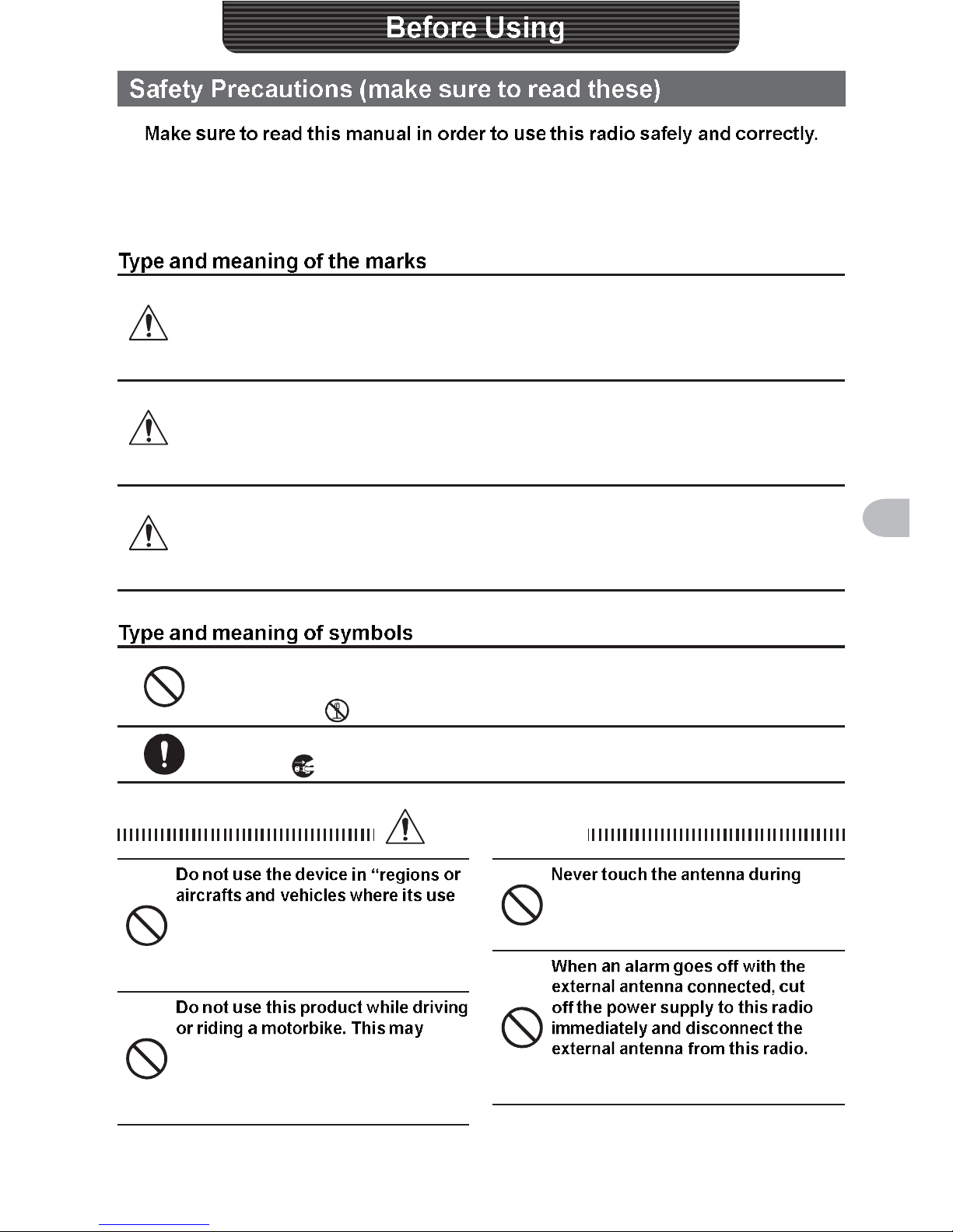
DANGER
This symbol indicates the possibility of death or serious
injury being inflicted on the user and the surrounding
people when these instructions are ignored and the product
is handled wrongly.
WARNING
This symbol indicates the possibility of death or serious
injury being inflicted on the user and the surrounding
people when these instructions are ignored and the product
is handled wrongly.
CAUTION
This symbol indicates the possibility of physical
impediments occurring or impediments being inflicted
on the user and the surrounding people when these
instructions are ignored and the product is handled wrongly.
Prohibited actions that must not be carried out in order to use this radio
safely.
For example, signifies that disassembly is prohibited.
Precautions that must be adhered to in order to use this radio safely. For
example, signifies that the power supply is to be disconnected.
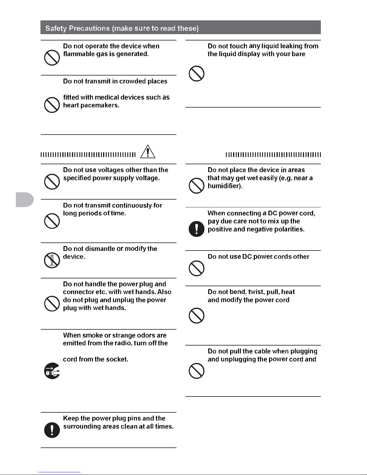
DANGER
is prohibited” such as in hospitals
and aeroplanes.
This may exert an impact on electronic
and medical devices.
result in accidents.
Make sure to stop the car in a safe
location first before use if the device is
going to be used by the driver.
transmission.
This may result in injury, electric shock
and equipment failure.
If not, this may result in fire, electric
shock and equipment failure.
10
Before Using
Doing so may result in fire and
explosion.
in consideration of people who are
Electromagnetic waves from the device
may affect the medical device, resulting
in accidents caused by malfunctions.
hands.
There is a risk of chemical burns
occurring when the liquid comes
into contact with the skin or gets into
the eyes. In this case, seek medical
treatment immediately.
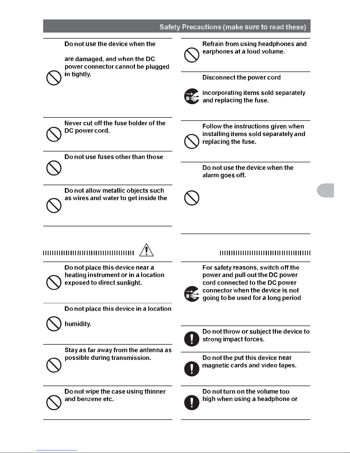
WARNING
Doing so may result in fire and electric
shock.
This may cause the temperature of the
main body to rise and result in burns
and failures due to overheating.
This may result in injury, electric shock
and equipment failure.
This may result in injury, liquid leak,
electric shock and equipment failure.
power and disconnect the power
This may result in fire, liquid leak,
overheating, damage, ignition and
equipment failure. Please contact our
company amateur customer support or
the retail store where you purchased
the device.
This may result in fire, liquid leak,
overheating, breakage, ignition etc.
This may result in fire, electric shock
and equipment failure.
This may result in fire, electric shock
and equipment failure.
than the one enclosed or specified.
This may result in fire, electric shock
and equipment failure.
and connection cables in an
unreasonable manner.
This may cut or damage the cables
and result in fire, electric shock and
equipment failure.
connection cables.
Please hold the plug or connector when
unplugging. If not, this may result in fire,
electric shock and equipment failure.
11
Before Using
power cord and connection cables
Please contact our company amateur
customer support or the retail store
where you purchased the device as this
may result in fire, electric shock and
equipment failure.
This may cause short-circuiting and
result in ignition and fire.
specified.
Doing so may result in fire and
equipment failure.
product.
This may result in fire, electric shock
and equipment failure.
Continuous exposure to loud volumes
may result in hearing impairment.
and connection cables before
This may result in fire, electric shock
and equipment failure.
This may result in fire, electric shock
and equipment failure.
For safety reasons, please pull the
power plug of the DC power equipment
connected to the product out of the AC
socket.
Never touch the antenna as well. This
may result in fire, electric shock and
equipment failure due to thunder.
CAUTION
This may result in deformation and
discoloration.
where there is a lot of dust and
Doing so may result in fire and
equipment failure.
Long-term exposure to electromagnetic
radiation may have a negative effect on
the human body.
Please use a soft and dry piece of cloth
to wipe away the stains on the case.
of time.
If not, this may result in fire and
overheating.
This may result in equipment failure.
The data in the cash card and video
tape etc. may be erased.
earphone.
This may result in hearing impairment.
12
Before Using
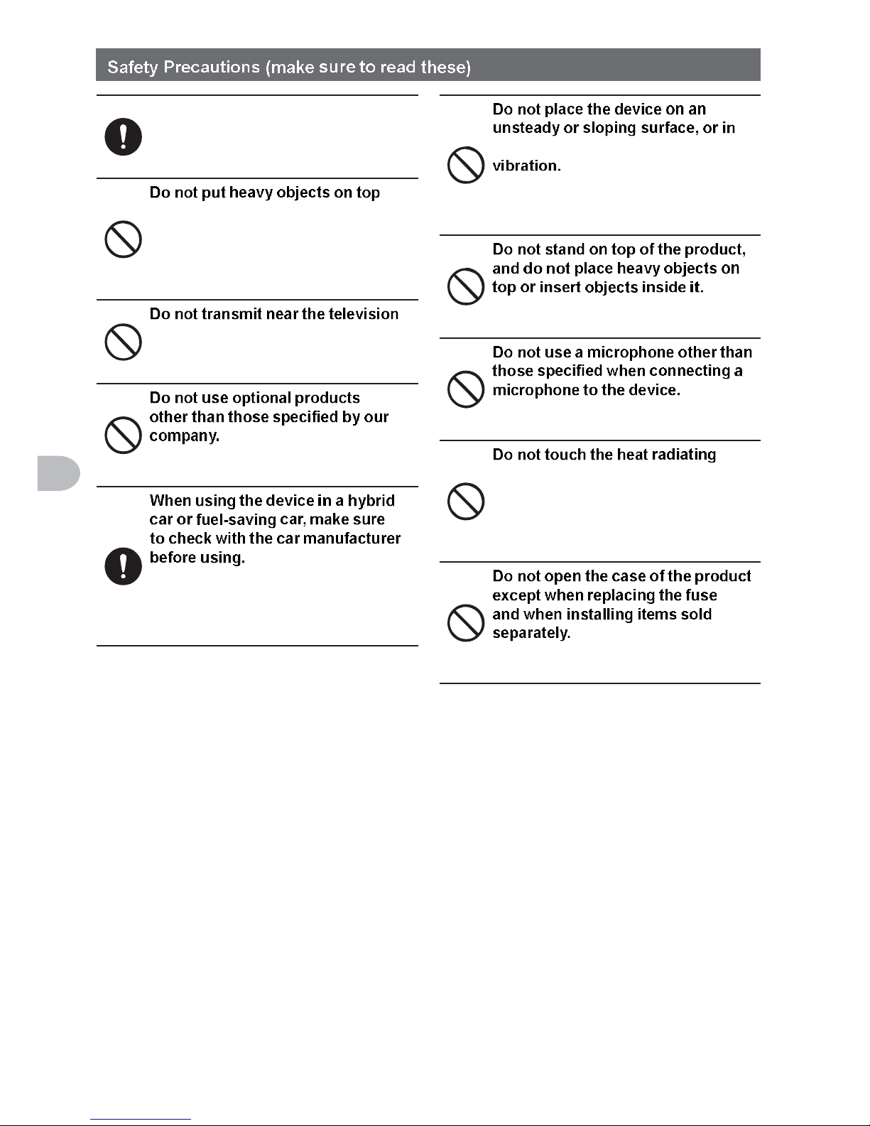
Keep out of the reach of small
children.
If not, this may result in injuries to
children.
of the power cord and connection
cables.
This may damage the power cord and
connection cables, resulting in fire and
electric shock.
and radio.
This may result in electromagnetic
interference.
If not, this may result in equipment
failure.
The device may not be able to receive
transmissions normally due to the
influence of noises from the electrical
devices (inverters etc.) fitted in the car.
a location where there is a lot of
The device may fall over or drop,
resulting in fire, injury and equipment
failure.
If not, this may result in equipment
failure.
If not, this may result in equipment
failure.
parts.
When used for a long period of time,
the temperature of the heat radiating
parts will get higher, resulting in burns
when touched.
This may result in injury, electric shock
and equipment failure.
13
Before Using
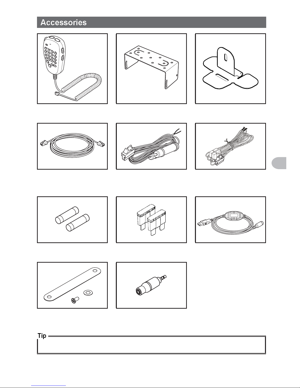
DTMF microphone
MH-48A6JA
Bracket for main body
MMB-36
Bracket for the
controller
Controller cable
(3 m)
DC power cable
(with fuse attached)
(USA, EXP version)
DC power cable
(with fuse attached)
(European version)
Spare fuse (15 A)
(USA, EXP version)
Spare Fuse (15 A)
(European version)
PC connection cable
SCU-20
Operating Manual
Warranty Card
Quick Manual
Microphone cord holder Stereo to Monaural Plug
Various optional parts are also available.
Refer to Page 206 for details.
14
Before Using
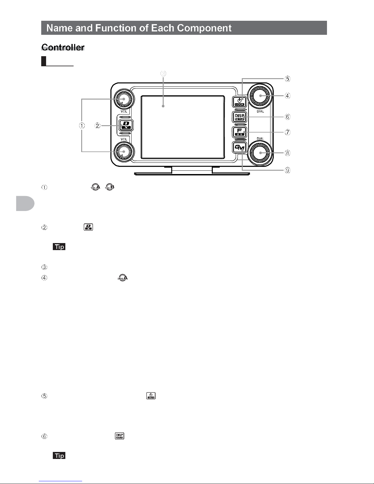
Front
VOL knob (
)
The volume will increase when the knob is turned in a clockwise direction and
decrease when turned in an counter-clockwise direction.
The upper end is for Band A use while the lower end is for Band B use.
D/X key ( )
The communication mode changes each time this key is pressed for a short time.
Refer to Page 45 for the communication mode.
WIRES-X will start when this key is pressed for one second or longer.
Touch panel display
Band A DIAL knob ( )
• The frequency of the upper band in the dual band display can be adjusted.
The frequency will increase when the knob is turned in a clockwise direction and
decrease when turned in an counter-clockwise direction.
Press the knob to enable setting the operating band frequency in 1 MHz units.
Press the knob for one second or longer to enable setting the frequency in 5 MHz
units.
• In memory mode when the knob is pressed for one second or longer, if a tag
(name) is attached to the memory channel, the tag and frequency displays will be
reversed.
• This knob is also used to select the items during the set up and memory
operations, group monitor operations, etc.
Power supply/LOCK switch ( )
Press this button for 2 seconds or longer to switch the power on and off.
The key lock can be engaged or released by pressing the button quickly while the
radio is turned on.
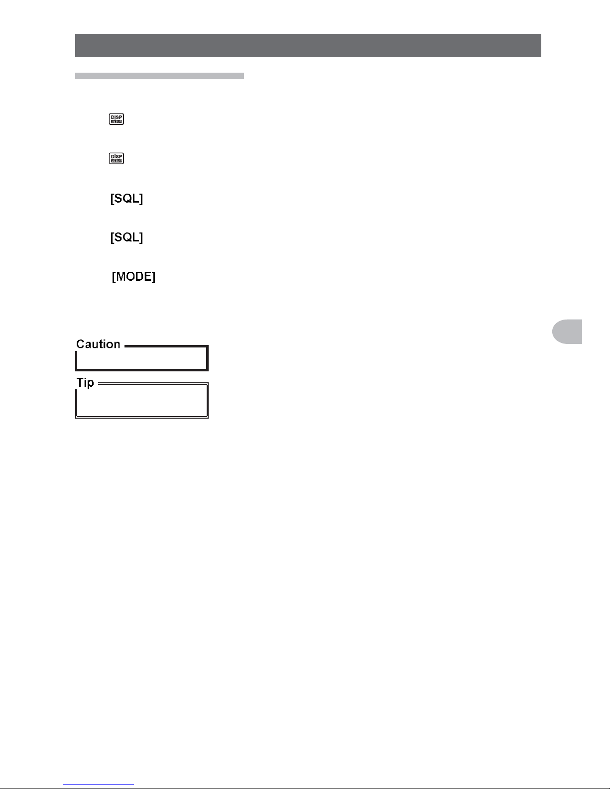
DISP/SETUP key ( )
The display screen will change each time the button is pressed quickly.
Refer to Page 20 for the display.
Press the button for one second or longer to display the set-up menu.
15
Before Using
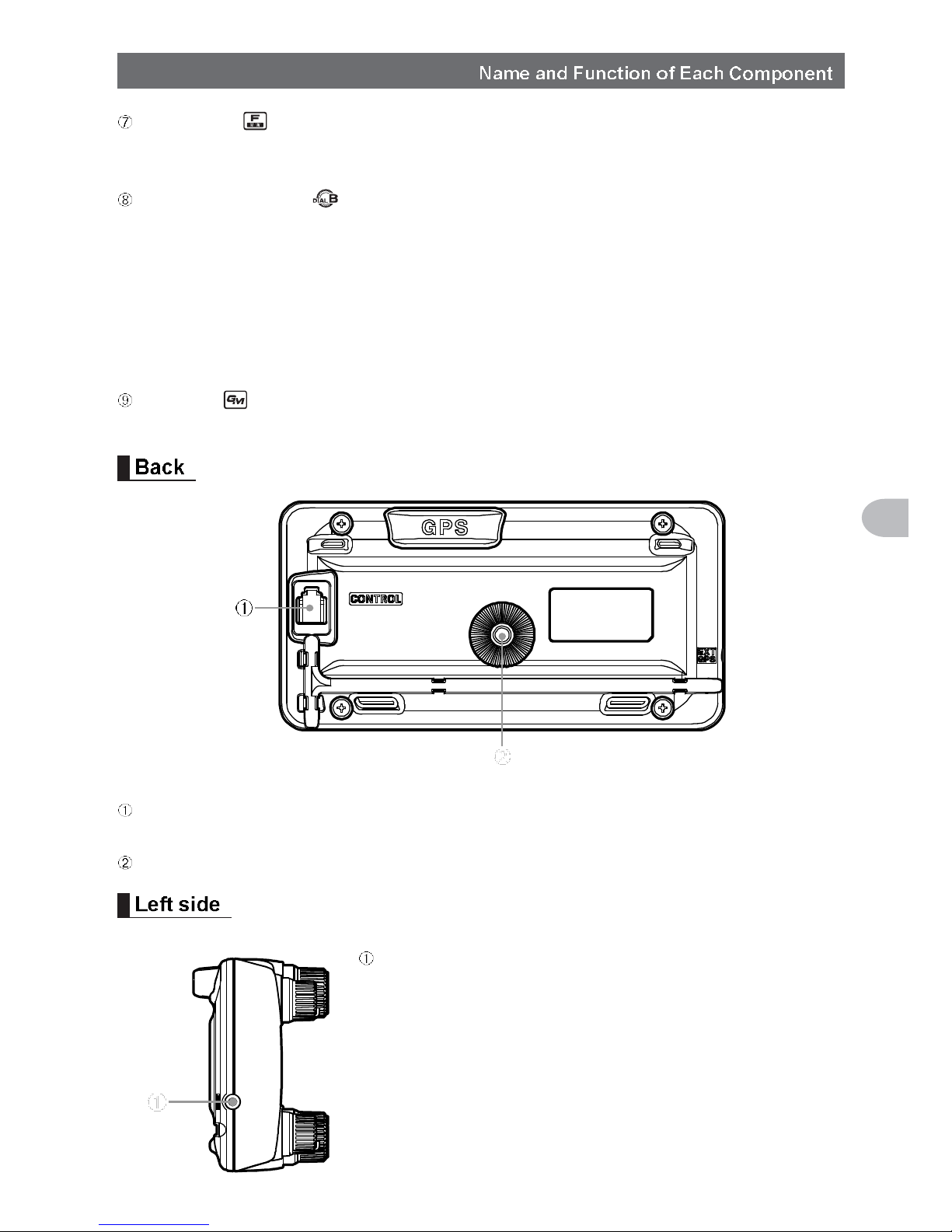
F/MW key ( )
Press the button quickly to display the function menu.
Press the button for 2 seconds or longer to change to the memory writing mode.
Band B DIAL knob ( )
• The frequency of the upper band in the dual band display can be adjusted.
Press the knob to enable setting the operating band frequency in 1 MHz units.
Press the knob for one second or longer to enable setting the frequency in 5 MHz
units.
• In memory mode when the knob is pressed for one second or longer, if a tag
(name) is attached to the memory channel, the tag and frequency displays will be
reversed.
GM key (
)
Press this key to start the group monitor function.
CONTROL jack
Plug in the control cable into this jack to connect with the main body.
Screw hole to attach the mounting bracket
EXT GPS jack
Plug in a cable to connect with external GPS devices.
16
Before Using
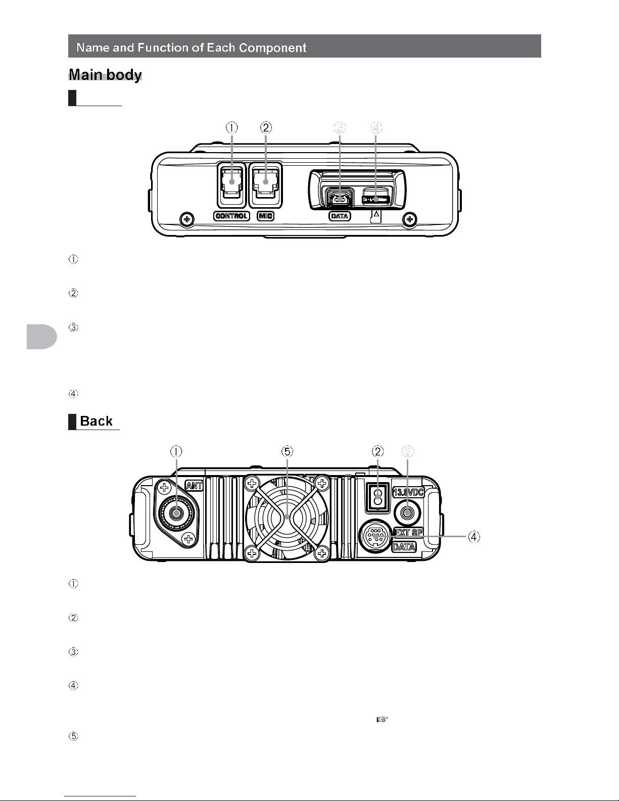
Front
CONTROL jack
Plug in the control cable into this jack to connect with the controller.
MIC jack
Plug in the provided microphone cable.
DATA jack
Connect MH-85A11U, the optional speaker microphone with camera.
* There is no audio output available from the FTM-400DR/DE to the MH-85A11U
speaker.
micro-SD card slot
ANT terminal
Connect the co-axial cable for the antenna.
13.8 VDC
Connect the provided DC power supply cable (with fuse attached).
EXT SP jack
Connect the optional external speaker.
DATA jack
Connect a cable for remote operation or the cable for connecting with the personal
computer interface unit and the external terminal unit ( P.155 Page).
Cooling fan
17
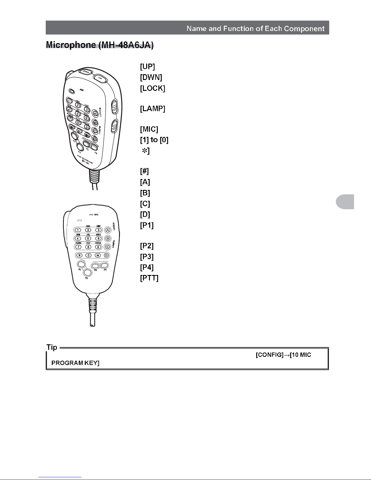
Before Using
Frequency is increased by 1 step.
Frequency is decreased by 1 step.
Locks / unlocks the [UP] and [DWN] keys and
[P1] to [P4] keys.
Turns the lamp on the body of the microphone
on/off.
Speak into here during transmission.
Enters the numbers and letters.
[ Changes the VFO/Memory operating mode of
the operating band.
Activates the GM (Group Monitor) functions.
Switches the operating band to Band A.
Switches the operating band to Band B.
Adjusts the squelch level.
Switches the display.
Turns off the squelch
(T.CALL: European version).
Recalls the receiver home channel.
Changes the communication mode.
Changes the transmit power.
Press this key to begin the transmit mode.
Preferred functions can be assigned to buttons [P1] to [P4]. Select using the
in the set-up menu.
18
Before Using
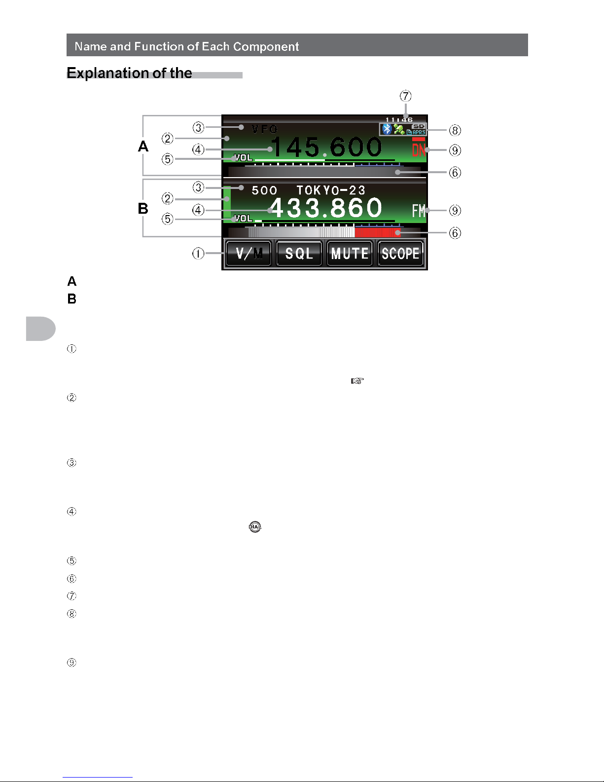
screen
Band A display area
Band B display area
The characters of the name tag and frequency are displayed in white for the
operating band, and gray for the sub-band.
Touch key display area
Functions to be displayed in the function menu screen can be assigned to the touch
keys. Refer to “Changing the touch key functions” ( P.121) for details.
Status display area
A green bar is displayed during receive and when signals are detected.
The bar will not be displayed when the squelch is turned on.
A red bar is displayed when transmitting.
Tag display area
“VFO” is displayed in the VFO mode.
The memory channel number and the tag are displayed in the memory mode.
Frequency display area
In the memory mode, pressing for one second or longer will display the memory
channel tag.
VOL/SQL level display area
S-meter/transmit power level display, and also partner station information display
Clock/Voltage display area
Icon display area
Bluetooth, APRS, micro-SD card and GPS icons are displayed when each function is
in use.
Communication mode display area
The analog and digital modes are indicated using symbols.
A red bar will be displayed above the symbol in the AMS (auto mode). The AMS
automatically matches the communication mode of the received signal.
* Digital communications can operate in Band A only.
19
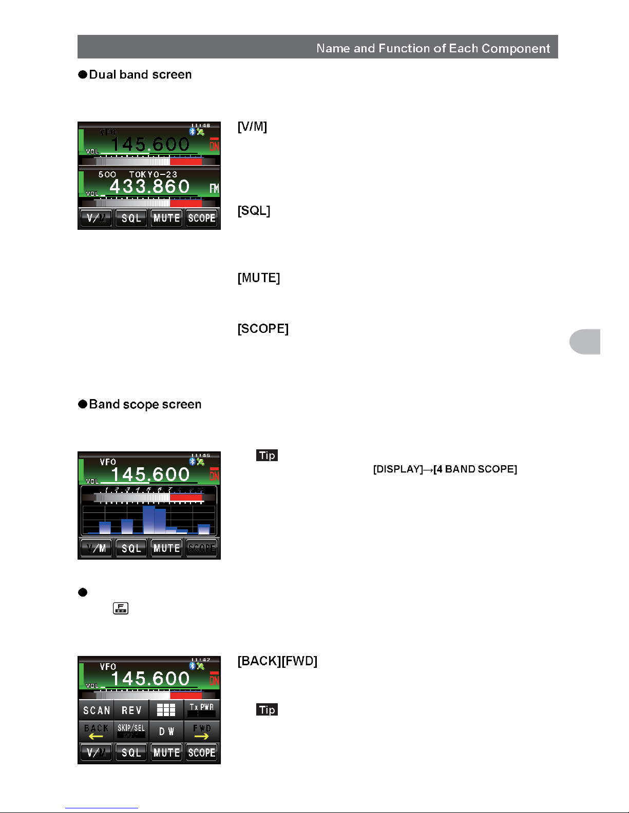
Before Using
Band A and Band B will be displayed at the top and bottom.
The VFO channel and memory channel will be
switched by touching this symbol.
The “V” is displayed in orange in the VFO
mode while the “M” is displayed in orange in
the memory mode.
The squelch level can be set after touching this
symbol. The characters are displayed in orange
for 5 seconds during the time that the squelch
level can be set.
The receive audio can be muted by touching
this. The characters are displayed in orange
when the sound has been muted.
The band scope operation toggles on or
off each time this symbol is touched. The
characters are displayed in orange during the
band scope operation.
The screen appears as shown, when the band scope is turned on.
The width of the band scope can be set to either “WIDE” or
“NARROW” under in the
set-up menu.
Function menu screen
When is pressed, the function menu is displayed on the screen under the operating
band.
The menu changes each time these symbols
are touched.
The functions displayed in the menu can be assigned to the
touch keys at the bottom of the display. Refer to Page 121
for details.
20
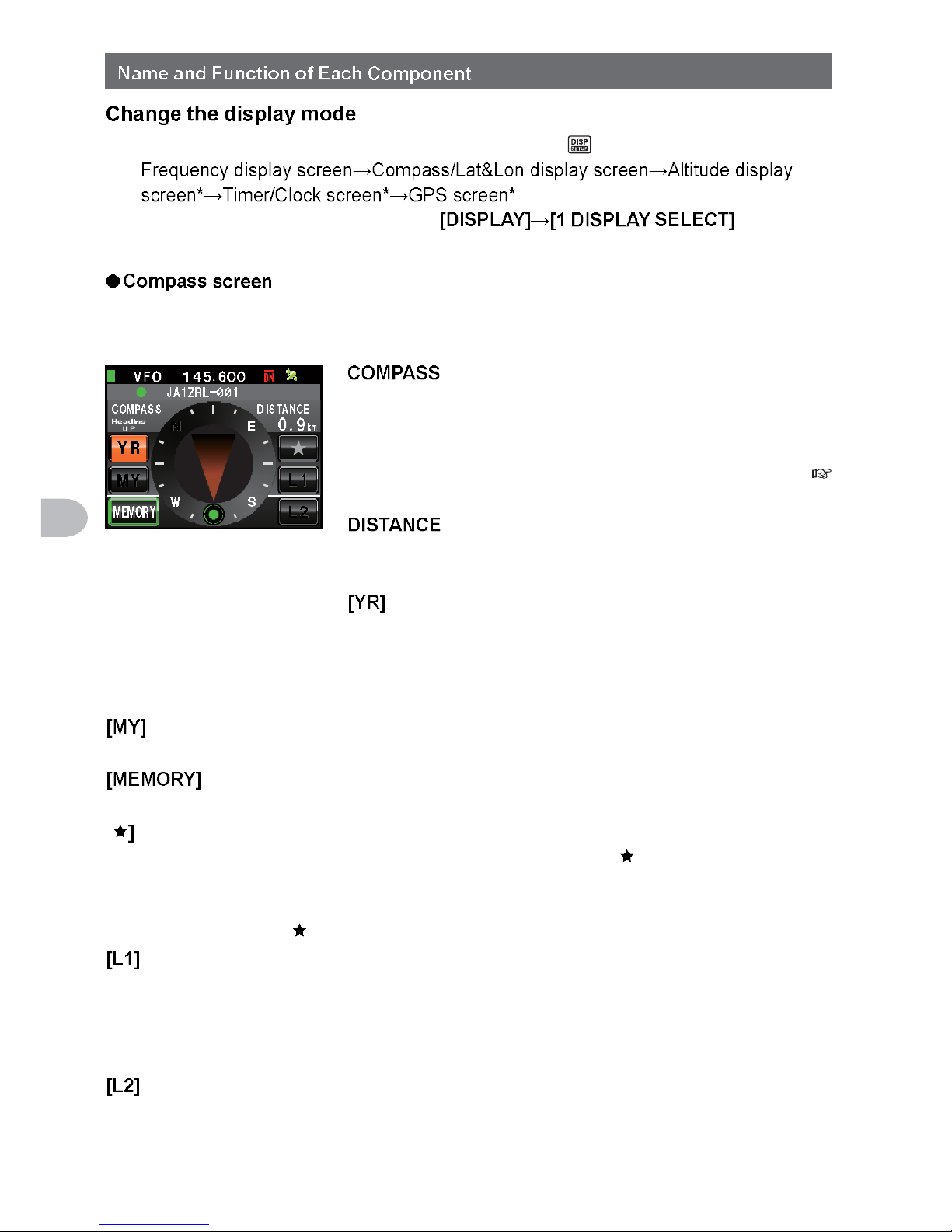
Before Using
The display mode will switch in the sequence each time is pressed.
* This screen will be displayed when is set to
“ON” in the set-up menu.
The direction of travel of your own station and direction coordinate of the received
station are displayed in the compass screen.
Displays the compass settings. There
are two settings, “Heading Up” where the
direction of travel is on top, and “North Up”
where North is always on top.
Refer to “Change the Compass Settings” (
P.94) for details.
When a saved position information is
recalled, the distance from the current
position is displayed.
When this symbol is touched, the position
of the partner station that is received is
displayed in the compass (when the position
information is included in the signal), and
the symbol is shown in orange.
When this symbol is touched, the direction of travel of your own station is
displayed in the compass, and this symbol is displayed in orange.
When this symbol is touched, the position information being displayed is
saved in the memory.
[ When this symbol is touched while the display is green, the position
information saved in the memory under the tag “ ” is displayed.
When this symbol is touched while the display is blinking, the position
information displayed in the compass will be saved in the memory under
the tag “ ”.
When this symbol is touched while the display is green, the position
information saved in the memory under the tag “L1” is displayed.
When this symbol is touched while the display is blinking, the position
information displayed in the compass will be saved in the memory under
the tag “L1”.
When this symbol is touched while the display is green, the position
information saved in the memory under the tag “L2” is displayed.
When this symbol is touched while the display is blinking, the position
information displayed in the compass will be saved in the memory under
the tag “L2”.
21
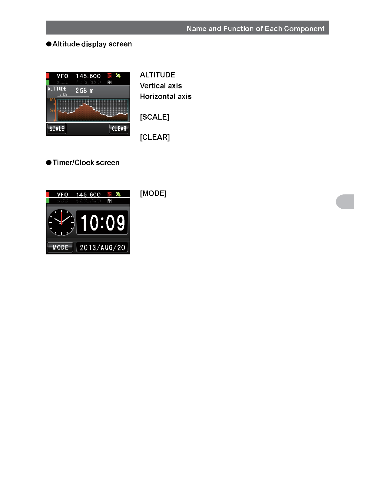
Before Using
The altitude of the current location is shown in the bar graph display.
Displays the current altitude.
Represents the altitude.
Represents the distance.
When this symbol is touched, the scale of
the distance changes.
When this symbol is touched, the graph
display will be cleared (erased).
The current time is shown in analog and digital formats. The date is also shown.
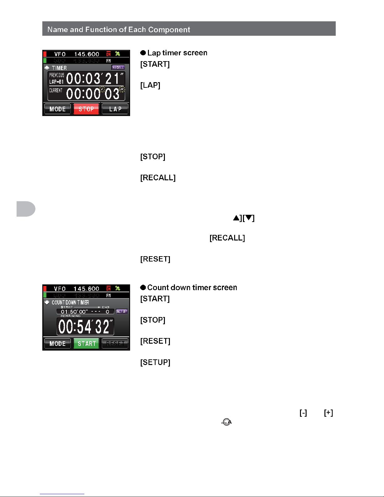
The mode switches between the lap timer
mode and the countdown timer mode each
time this symbol is touched.
22
Before Using
The count starts when this symbol is
touched.
The lap time is then saved in the memory (a
maximum of 99 lap times can be saved) and
displayed in the upper lap display window
when this symbol is touched.
The lap time (of the new interval) being
measured will be displayed in the lower lap
display window.
The count stops when this symbol is
touched.
When this symbol is touched, the lap time
saved in the memory is shown in the upper
lap display window while the split time is
shown below. When there are multiple lap
times, touch [ to move between the
lap times.
Touch again to return to the
measurement screen.
The counter is reset when this symbol is
touched.
The count starts when this symbol is
touched.
The count stops when this symbol is
touched.
The counter is reset when this symbol is
touched.
The count time can be changed (from 1
minute to 99 hours and 59 minutes) when
this symbol is touched. Each time this
symbol is touched, the setting will switch
from “Hours” to “Minutes” to “Confirm”. The
time can be changed by touching and
or turning .
23
Before Using
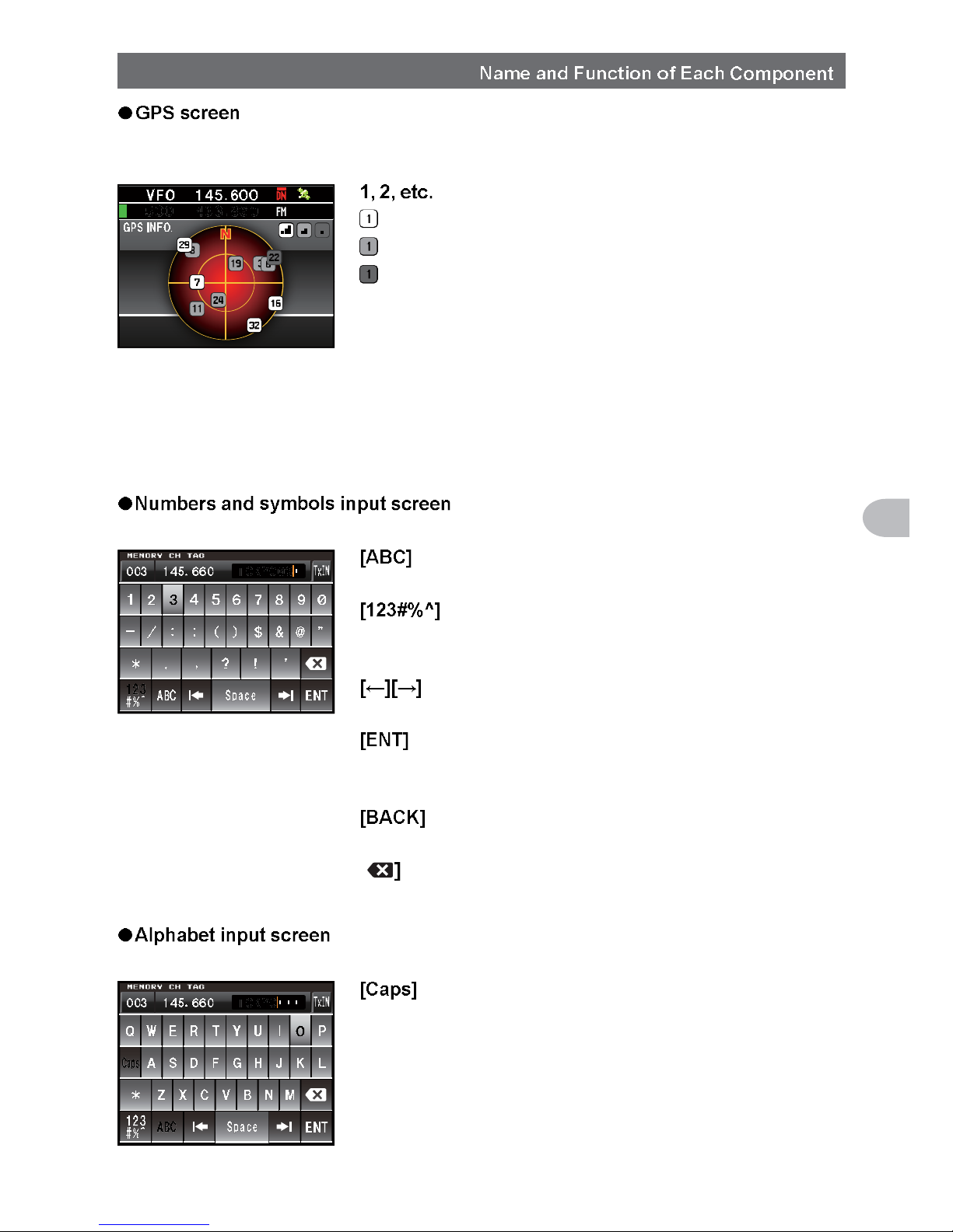
The GPS satellite statuses are shown with numbered icons.
Received satellite number
Signal strength High
Signal strength Medium
Signal strength Low
Input the character
The keyboard screen is displayed when entering a memory channel tag or the call sign
of your own station.
The screen changes to the alphabet input
screen when this symbol is touched.
The screen changes to the input screen for
numbers and symbols each time this symbol
is touched.
The cursor in the input field moves left and
right when these symbols are touched.
The entered characters are confirmed and
the display returns to the previous screen
when this symbol is touched.
The display returns to the previous screen
when this symbol is touched.
[ One character to the left of the cursor is
erased when this symbol is touched.
The input switches between small and
capital letters input each time this symbol is
touched.
24
Installation and Connection
Note the following when installing this radio.
Do not install the radio in a place where there is extreme vibration, where there is a
lot of dust, excessive humidity or high temperature, or where it is exposed to direct
sunlight.
Install the radio in a well ventilated position, so heat release is not obstructed
because the heat sink gets hot when transmitting for a long periods of time.
Do not place any objects on top of the main body.
Do not lift up or hold the controller by holding the knob or control cable.
A regulated, negative ground 13.8 V DC power supply is required for this radio.
Check that the car battery is a negative ground 12 V system when using this radio in
a mobile unit. Never connect this radio to the 24 V battery of a large vehicle.
Never connect this radio to a 120 V AC power source.
Note that there is a risk that hum and noise may be introduced, depending on the
installation condition and the external power source used.
Install the device as far away as possible from the TV and radio to avoid TV and radio
interference (TVI, BCI).
In particular, do not install this radio near indoor antenna elements.
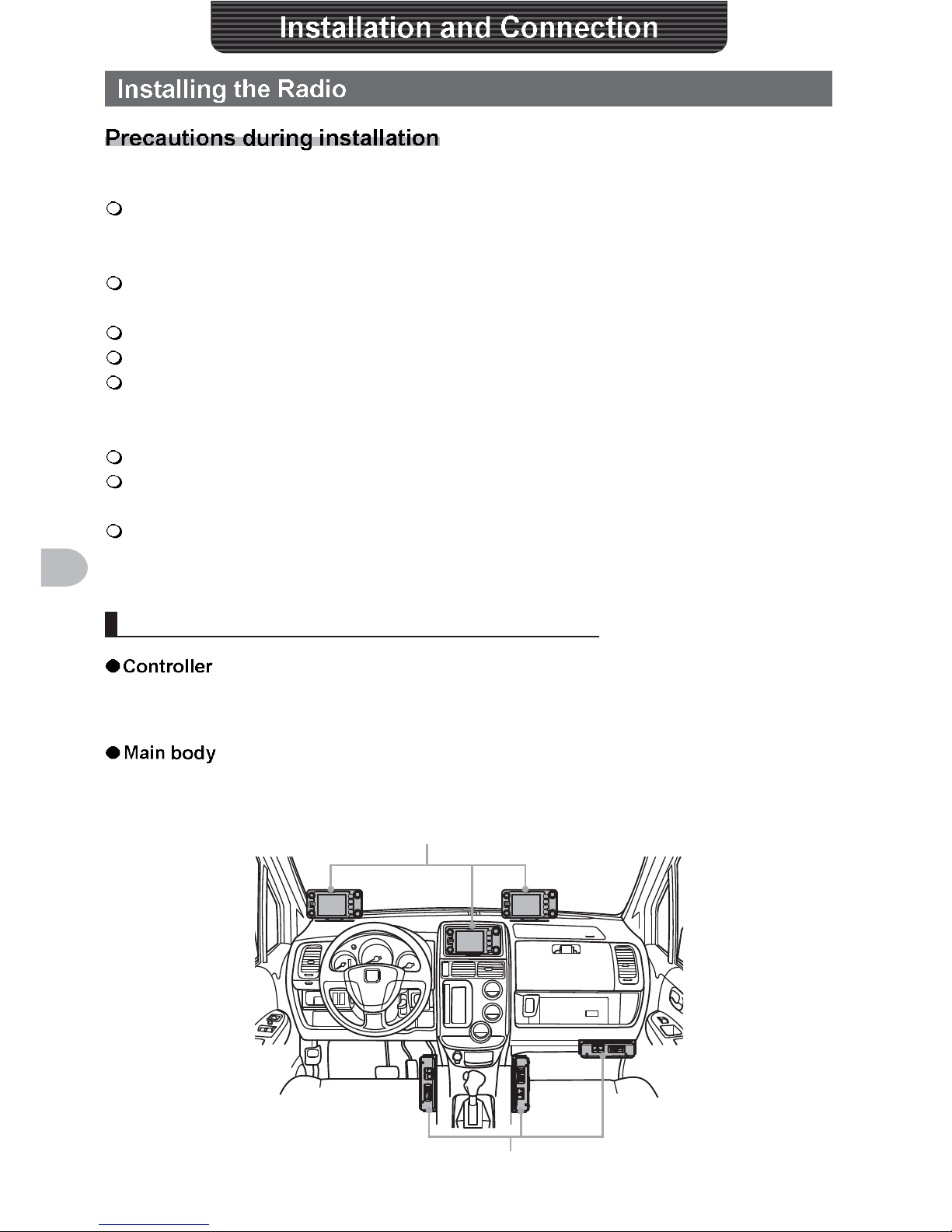
Installation location when used in a mobile unit
It is recommended that the controller be installed on top of the car dash board or in front
of the center console. Refer to Page 28 on how to install the controller.
It is recommended that the main body be installed below the car dash board or to the
side of the center console. Refer to Page 27 on how to install the main body.
Controller
Radio main body
25
Installation and Connection
antenna
A good antenna installation is extremely important for transmission and reception
purposes. Note the following, as the type and characteristics of the antenna largely
determines whether the performance of the radio can be fully realized.
• Use an antenna that suits the installation conditions and application objective.
• Use an antenna that suits the operating frequency band.
•
• Adjust the VSWR (standing wave ratio) until it is 1.5 or less for an antenna with an
• Keep the co-axial cable routing length as short as possible.
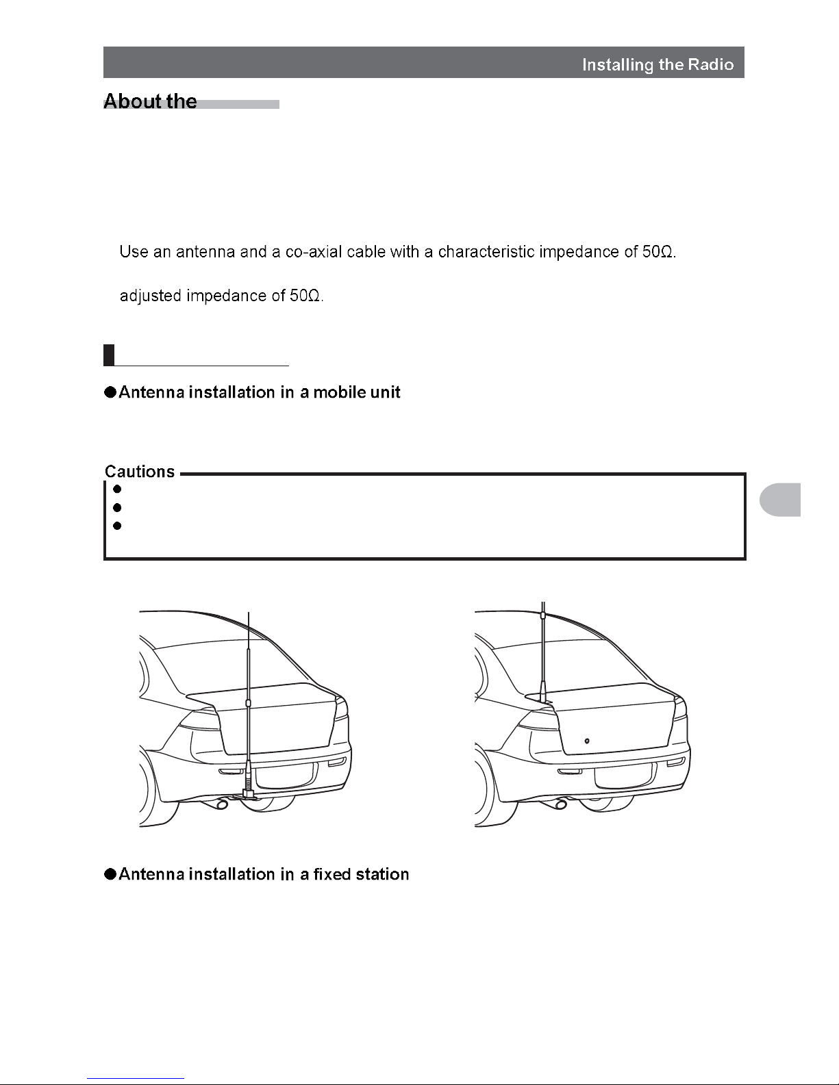
Install the antenna
Mount the antenna base at the rear of the car (rear bumper, trunk, rear gate, etc.) and
then attach the antenna to the base.
Ensure that the antenna base is securely grounded to the car body.
Avoid routing the co-axial cable enclosed with a commercial car antenna cable.
Do not allow rain water or moisture to penetrate the cable or connectors when laying the co-axial
cable inside the car.
Bumper type Trunk type
There are omni-directional, and directed array antennas for use in an outdoor setting.
• Omni-directional antennas such as the GP (Ground Plane) antenna are suitable for
communications between a local station and mobile stations in all direction.
• Directional antennas such as the Yagi antenna are suitable for communications
between a base station and a remote station in a specific direction.
26
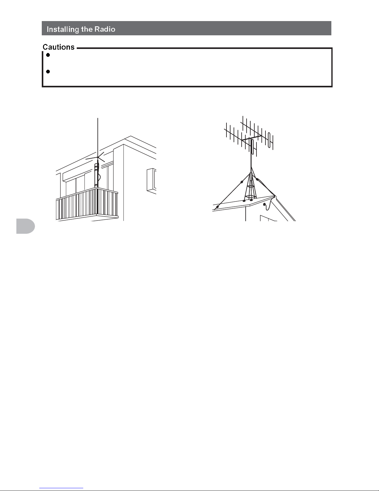
Installation and Connection
Create a loop (slack) in the co-axial cable directly underneath the antenna and fasten it so that the
weight of the cable does not pull on the antenna or connector itself.
Install the antenna taking into consideration the securing supports and how the guying wires are
positioned, so that the antenna does not fall over or get blown away in strong winds.
GP antenna
<Veranda Mounted Example>
Yagi antenna
<Roof Mounted Example>
27
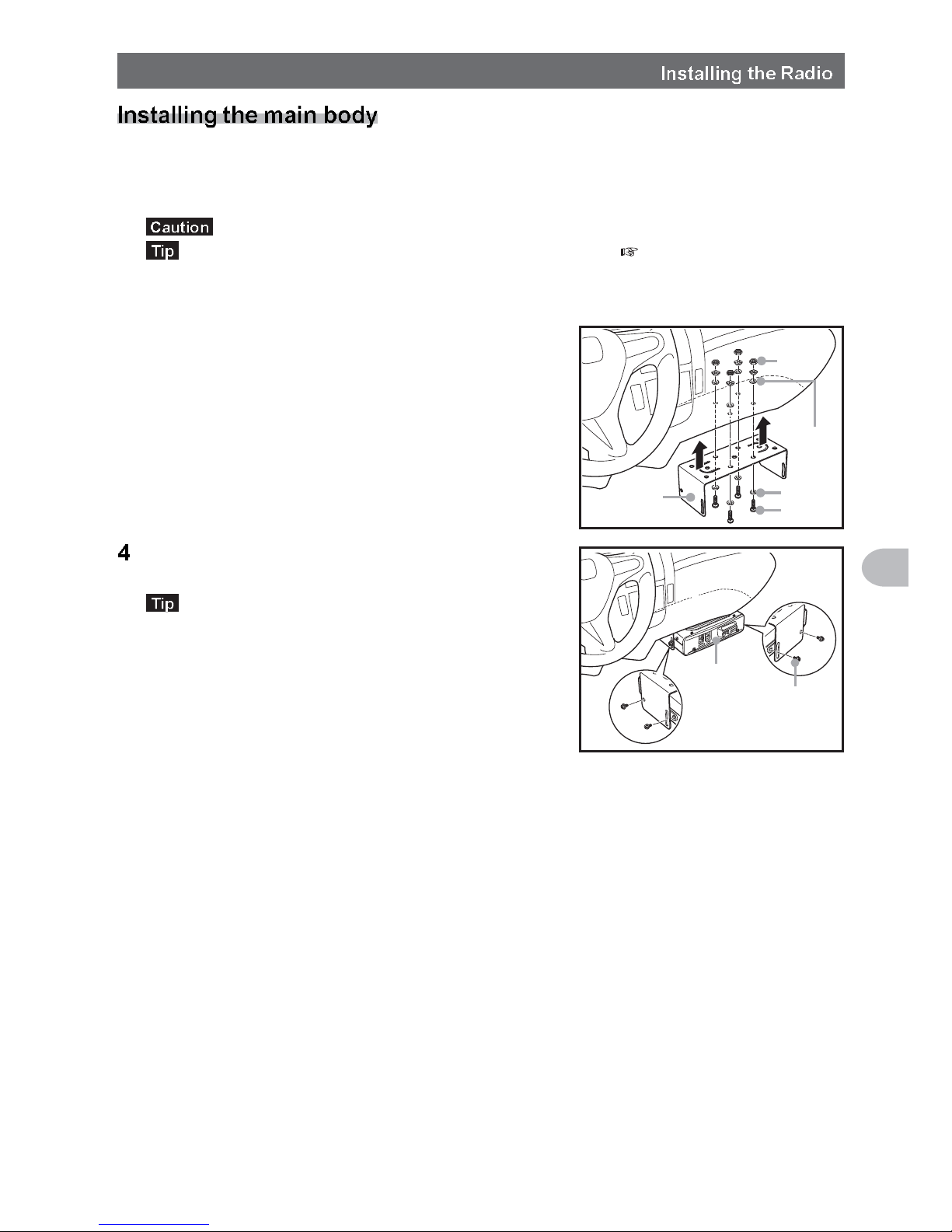
Installation and Connection
Install the main body using the provided MMB-36 bracket.
1 Select the installation location
Select a location where the antenna coax and power cable can be securely attached.
Also refer to “Installation location when used in a mobile unit” ( P.24).
2 Drill four 6 mm diameter holes in the location where the bracket is to be mounted,
matching the positions of the bolting holes of the bracket
3 Attach the bracket using the provided bolts, nuts
and washers
Nut
Washer
Washer
Bolt
Bracket
Fasten the main body to the bracket, using the
provided flange bolts, as shown in the drawing
The mounting angle can be changed depending on
the securing position of the flange bolts.
Flange bolt
Main body
28
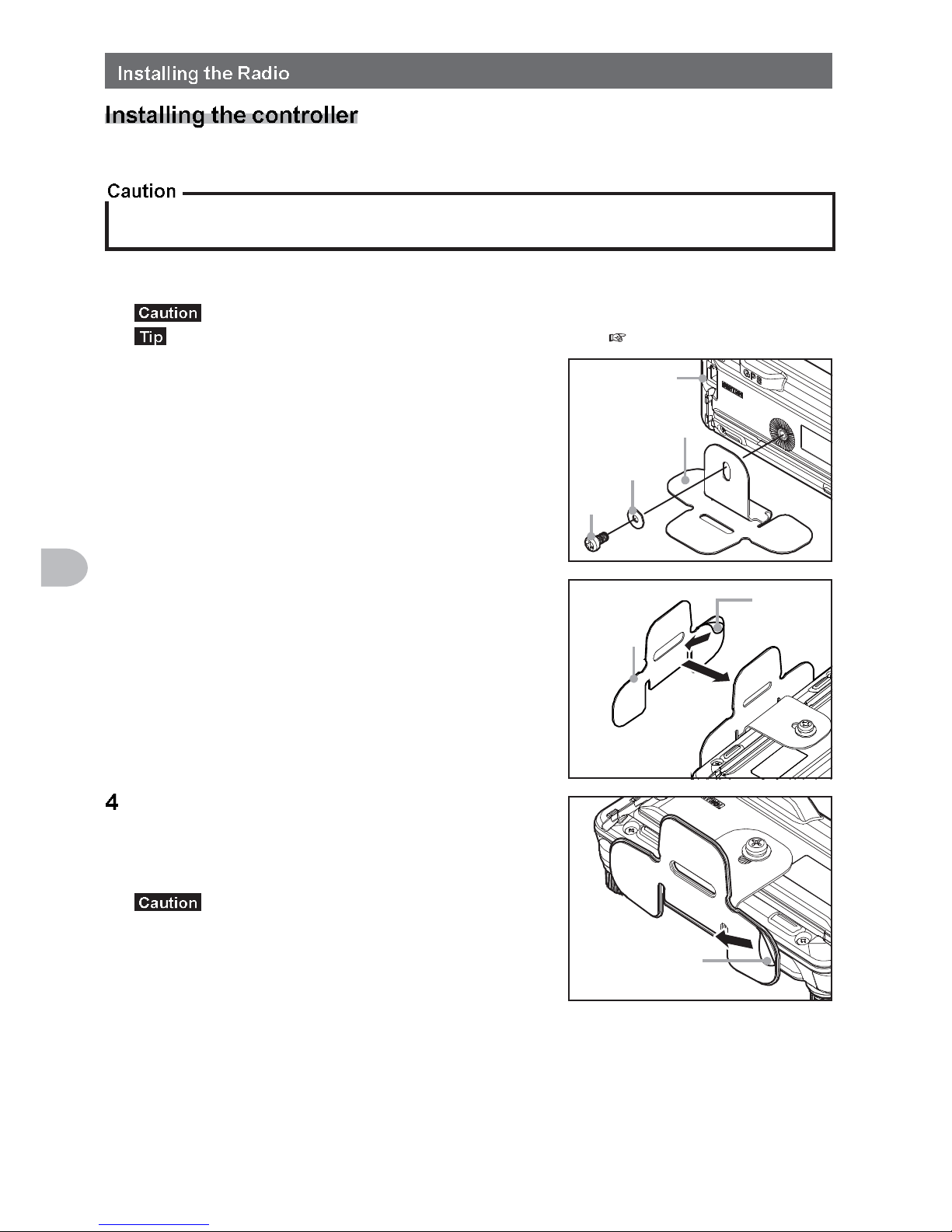
Installation and Connection
Install the controller using the provided bracket.
The bracket can be bent by hand to match the location where the controller is going to be installed.
Take due care not to injure yourself when bending the bracket.
1 Select the installation location
Select a stable, flat location with as few dents and protrusions as possible.
Also refer to “Installation location when used in a mobile unit” ( P.24).
2 Fix the bracket to the controller using the
provided screws and washers, as shown in the
drawing
Controller
Bracket
Washer
Screw
3 Peel off the protective seal from one side of the
provided two-sided adhesive sheet, and paste it
onto the bottom of the bracket
Protection
seal
Two-sided
adhesive
sheet
Peel off the other protection seal from the
underside of the two-sided adhesive sheet pasted
onto the bracket, and then stick the bracket to the
installation location
Remove all dirt and dust from the installation
location before affixing the bracket.
Protection seal
29
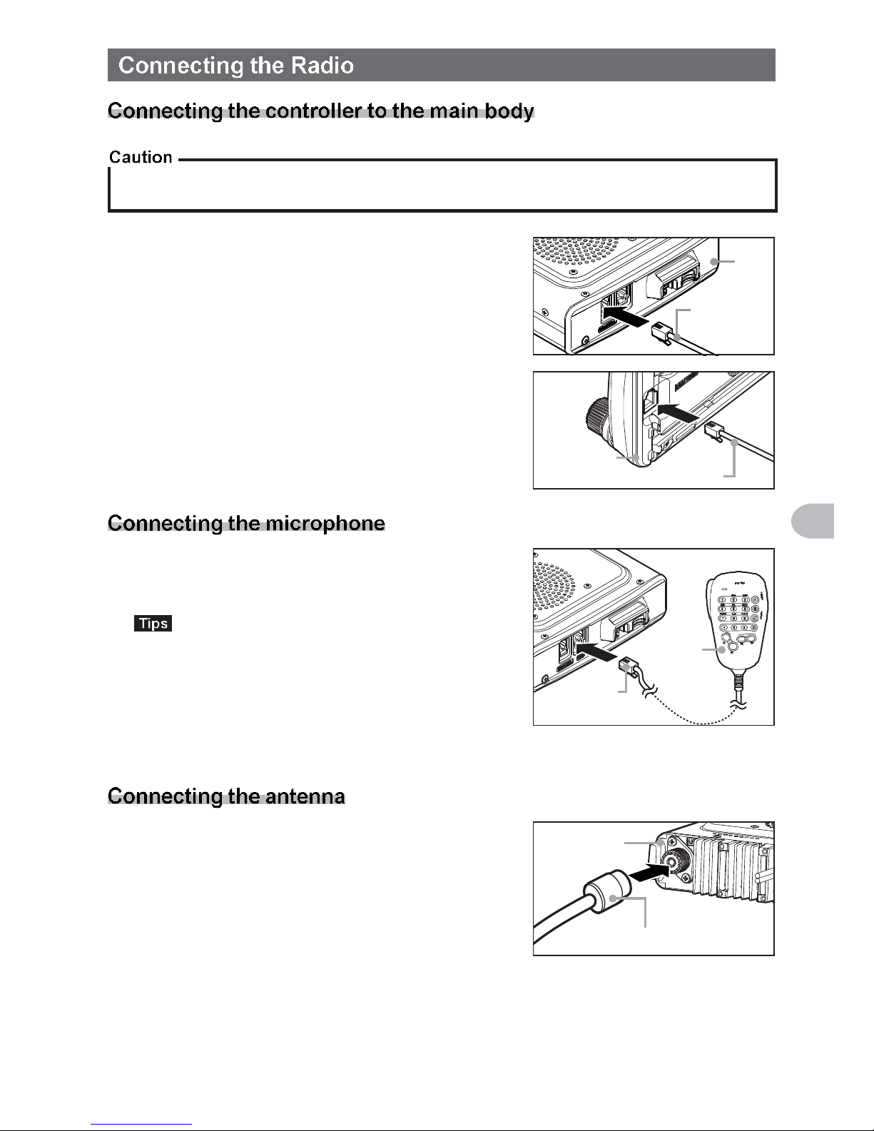
Installation and Connection
Make sure the power supply is switched OFF before connecting the cable between the controller and
the main body.
1 Plug the connector of the controller cable into the
[CONTROL] jack at the front of the main body
until a click sound is heard
Main
body
Controller
cable
2 Plug the other connector of the controller cable
into the [CONTROL] jack at the back of the
controller until a click sound is heard
Controller
Controller cable
1 Plug the microphone connector into the [MIC]
jack at the front of the main body until a click
sound is heard
• To remove the microphone, pull the connector out
while pressing the latch.
• Using the optional microphone extension kit “MEK2”, a microphone with a 8-pin connector can be
used. A microphone extension cable (about 3 m
long) is also included in MEK-2. Use it to install the
microphone in locations which cannot be reached
by the attached microphone cable.
Microphone
Connector
1 Attach the antenna co-axial cable to the [ANT]
terminal at the back of the main body and tighten
the connector
Main body
(rear side)
Co-axial cable connector
30
Installation and Connection
When using this radio as a mobile unit, connect the DC power supply cable to the
negative ground 12 V car battery.
Use the radio in a car with a negative ground 12 V DC system, where the minus (-) pole of the
battery is connected to the car body.
Do not connect the radio to the 24 V battery of a large vehicle.
Do not use the cigarette lighter inside the car as a power source.
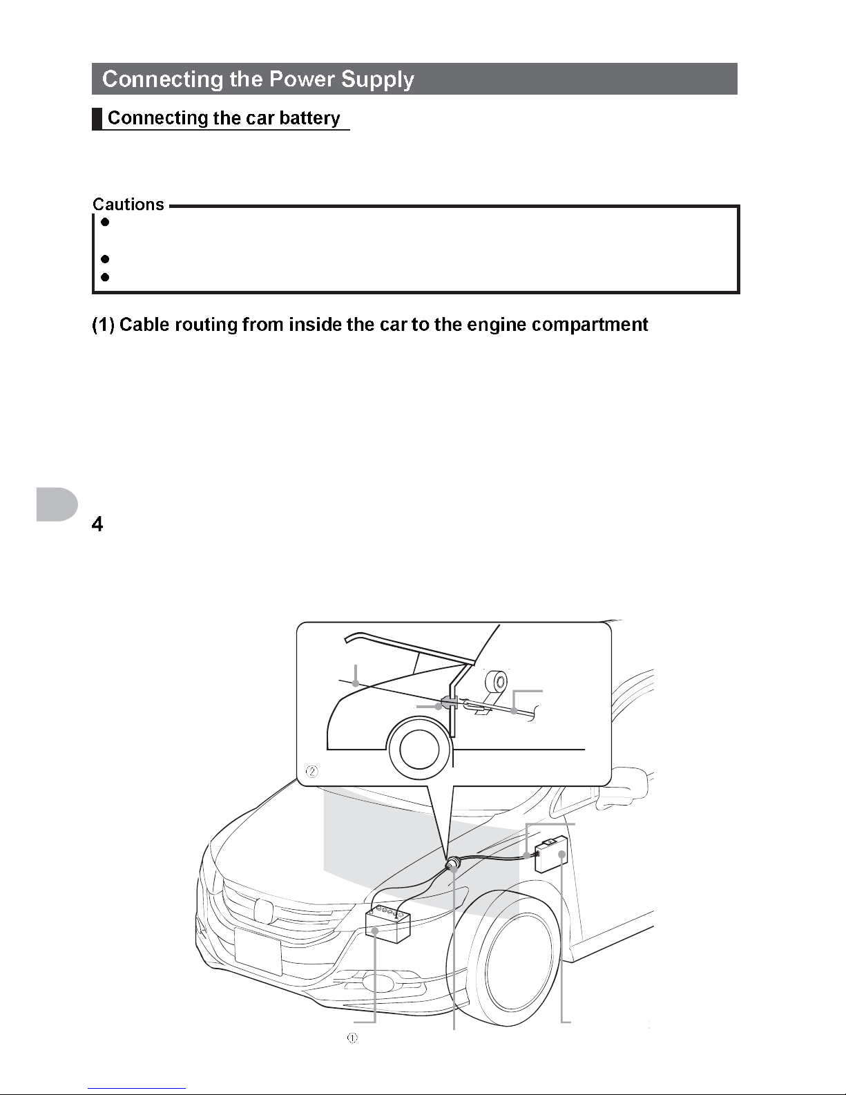
Rout the DC power supply cable to the engine compartment, passing it through a
grommet in the fire wall from the passenger side.
1 Feed a hardened wire from the engine compartment through the grommet into the
interior of the car
2 Hook the end of the “feed” wire with the “bare wire” end of the provided DC power
supply cable
3 Fold and bend the ends of the wires and wind insulation tape around them
Pull the “feed” wire back into the engine compartment
The DC power supply cable will be pulled through the grommet into the engine
compartment.
5 Peel off the tape and remove the DC power supply cable from the “feed” wire
Hardened wire
Grommet
Battery (12V)
Tape
DC power
supply cable
(accessory)
DC power
supply
cable
Pass the cable through the grommet
Radio main
body
 Loading...