

Page 1
FT
O
PERATION
DX
TFT
9000
M
ANUAL
FTDX9000 TFT OPERATION MANUAL
Page 2

PLEASE READ THIS FIRST
When turning on the transceiver for the first time, please set the local time as soon as possible. If this is not
done, the various functions of the World Clock and Great Circle Map will not function correctly.
Note: If you wish to add a city to the City List that was programmed at the factory, you will need to supply your
own USB or PS2 Keyboard. If you utilize one of the pre-loaded cities, a keyboard is not necessary.
You may also set up the local time for other locations, without a keyboard, using the cities that have been preloaded at the factory.
1. Powering Up the Transceiver
On the rear panel, move the Power switch to the
“I” position to apply power from the power supply.
The transceiver will not turn on yet, but power will
now be supplied to the OCXO.
Hold in the front panel POWER switch to turn the
transceiver on.
Note: The opening screen will appear on the TFT
display, and the self-check function of the CPU inside the radio will begin. Then, the µ-Tuning circuitry
will receive the data from the CPU, and it will perform
its own self-check, and will preset itself to the proper
settings for the current operating frequency.
While the µ-Tuning circuitry is obtaining the data, the
drive mechanism will move from one end of its range
to the other end (fast), and this will cause a temporary “motor” noise that can be heard; this, does not
represent any trouble or problem.
When the radio is turned on for the first time, it takes
about 50 seconds (from turning the radio on to completing the self- check) until the radio becomes ready
to use; however, from the next time you turn it on, it
will take around 10 seconds until the transceiver is
ready for full operation.
2. Local Time Setup
On the TFT, there should be a World Map dis-
played; if the World Map does not appear, find the
[
DISP](Display) key below and to the right of the
TFT; press this key as many times as required to
get the World Map to display on the TFT.
Below the TFT, press the [F1](SET) key; the TFT
should now show LOCAL TIME -1; this setting
has been pre-set for Japanese time at the factory.
3. Changing the Location
To set the (highlighted) Time Zone, press the
[F7](
SELECT) key to engage setting of the de-
sired Time Zone. Use the [F1]() ~ [F4]() keys
to choose the Time Zone, then press the
[F7](
SELECT) key once more.
The name of the country associated with the high-
lighted Time Zone may now be selected using the
[F1]()
you have made your selection.
You may now choose one of the cities displayed
in the same way. When you have made your
choice, press the [F7](SELECT) key.
Advice: Depending on the country, there may be only
one city (or no cities) listed. In these instances, to
modify the setting, please first select the city name
on the list, even if you do not see the city you want on
the list; you may modify the city name later.
~ [F1]() keys. Press [F7](SELECT) when
4. Changing the City Name
(Please connect a PS/2 or USB Keyboard (not supplied) to do manual entry of a city name. If you are
not entering a new city name, please skip to step (5)
below).
Use the [F1]() and [F2]() keys to highlight the
city name you wish to change. Now, press the
[F7](
SELECT) key, then enter the name of the de-
sired city.
When you have completed your input, press the
[F7](
SELECT) key once more.
5. Correcting the Date
Use the [F1]() and [F2]() keys to highlight
“DATE,” then press the [F7](SELECT) key.
Use the [F3]() and [F4]() keys to navigate to
each column of the date, then use the [F1](
and [F2]() keys to select the desired numbers
in each column. Repeat for each column, to complete the date.
When entry is complete, press the [F7](SELECT
key.
)
)
FTDX9000 TFT OPERATION MANUAL
Page 3

PLEASE READ THIS FIRST
6. Time Setting
Press the [F1]() and [F2]() keys to highlight
“TIME,” then press the [F7](SELECT) key to enter the time entry mode.
Use the [F3]() and [F4]() keys to navigate to
the desired column in the date, then use the
[F1]()
number in each column. Time is entered in 24hour format.
When entry is complete, press the [F7](SELECT
key.
and [F2]() keys to select the desired
7. Setting up Daylight Saving Time
Once you have selected the city to be utilized, use
the [F1]() and [F2]() keys to highlight DST
(DAYLIGHT SAVING TIME).
Use the [F3]() and [F4]() keys to choose ON
or OFF.
8. Saving and Closing
When you have completed all the above entries
to your satisfaction, press and hold in the
[F7](
SELECT) key for two seconds to save all the
new settings. The chosen city and time zone will
appear on the World Map page.
Note: The [F1](SET) key is only used when setting
the city name and local time. If you make a mistake,
)
press the [F7](SELECT) key momentarily. Pressing
the [F7](SELECT) key for two seconds will return you
to the World Map screen.
FTDX9000 TFT OPERATION MANUAL
Page 4
BEFORE USING THE TFT DISPLAY
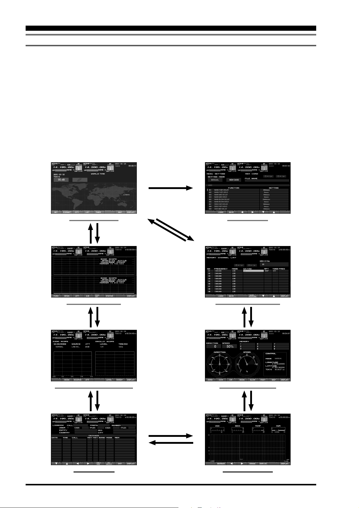
OPERATION OF THE TFT SCREEN
This TFT screen can show any of 8 different display
options, described on the following pages. These are:
World Clock, Spectrum Scope, Audio Scope/Oscilloscope, Log Book, Thermal Indication/SWR display,
Great-Circle Map/Rotator Control, and the Memory
Channel list. Also, the Menu will appear on the TFT, if
engaged. To move to the desired screen, use the
[
DISP](DISPLAY) key, located at the right low end of
the screen.
When the [DISP](DISPLAY) key is pressed momentarily, the screen changes, one by one, to the next
consecutive.
[
Press and hold in the
[
“WORLD CLOCK” Screen
DISP(DISPLAY)] button
If the [DISP](DISPLAY) key is pressed for 2 seconds,
the screen goes back to the previous screen.
If you do not want to change the setting, or if you
wish to suspend the setting procedure, press the
[
not be saved, and the screen will move forward to
the next display.
On each screen, the action of the function key may
vary. At the bottom area of the screen, the function is
indicated; please confirm the function displayed as
you read along.
Press the
MNU] button
DISP](DISPLAY) key. Any changes you started will
“MENU LIST” Screen
Press and hold in the
[
DISP(DISPLAY)] button
“SPECTRUM SCOPE” Screen
Press and hold in the
[
DISP(DISPLAY)] button
“AUDIO SCOPE/OSCILLO SCOPE” Screen
Press and hold in the
[
DISP(DISPLAY)] button
Press the
[
DISP(DISPLAY)] button
[
DISP(DISPLAY)] button
Press the
[
DISP(DISPLAY)] button
Press the
[
DISP(DISPLAY)] button
Press the
“MEMORY CHANNEL LIST” Screen
[
DISP(DISPLAY)] button
[
DISP(DISPLAY)] button
Press the
“ROTAT OR CONTROL” Screen
Press the
Press and hold in the
[
DISP(DISPLAY)] button
Press and hold in the
[
DISP(DISPLAY)] button
Page 2
Press the
[
DISP(DISPLAY)] button
Press and hold in the
[
DISP(DISPLAY)] button
“LOG BOOK” Screen “SWR MONITOR” Screen
FTDX9000 TFT OPERATION MANUAL
Page 5

BEFORE USING THE TFT DISPLAY
MENU MODE OPERATION
If you want to change a configuration setting of this
radio, you are able to display the Menu mode on the
TFT screen, so you can change it efficiently. In order
to enter the “Menu” mode, press the [MNU] key momentarily; the Menu screen will now appear on the
screen. By rotating the Main Tuning knob, you can
move to the desired item you want to change now
you can choose the revised setting by rotating the
CLAR/VFO-B knob. It is also possible to move the
Menu items and values by pressing the function keys
located below the TFT screen. For details, please
refer to “How to Use the Menu Mode.”
When you have completed the changes to the Menu
item(s), press and hold in the [MNU] key for 2 seconds; the setting(s) will now be saved. If you do not
want to save the new setting, press the [MNU] key
momentarily; the radio will revert to its previous condition.
There are 161 items in the Menu mode, and they are
grouped; the group name is displayed at the left top
of the list screen. It will be convenient for you if you
initially select the group, by rotating the Main Tuning
knob, and then select the item you want.
The groups are as follows.
1. AGC:
2. DISPLAY:
3. FH-2:
4. GENERAL:
5. MODE-AM, MODE-CW, MODE-DATA, MODE-
DM, MODE-PKT, MODE-RTTY, MODE-SSB
6. RX AUDIO:
7. RX DSP: RX Filter bandwidth and shaping
8. SCOPE: Setup of the starting frequency for the
Spectrum Scope
9. TUNING: Setup of the Dial steps
10.TX AUDIO: Setup of the Parametric Equalizer
11. TX GNRL:Setup of the
For detailed information regarding the Menu mode,
please see the “How to Use the Menu Mode” section
of this manual, and the operation manual of the radio.
MENU MODE RESET
It is possible to reset (only) the Menu mode settings back to their factory default. Do this if you
want to clear all settings out, and start fresh with
the original values.
1. Turn off the radio.
2. Turn the radio on while pressing and holding
in the [MNU] key.
FTDX9000 TFT OPERATION MANUAL
Page 3
Page 6
BEFORE USING THE TFT DISPLAY
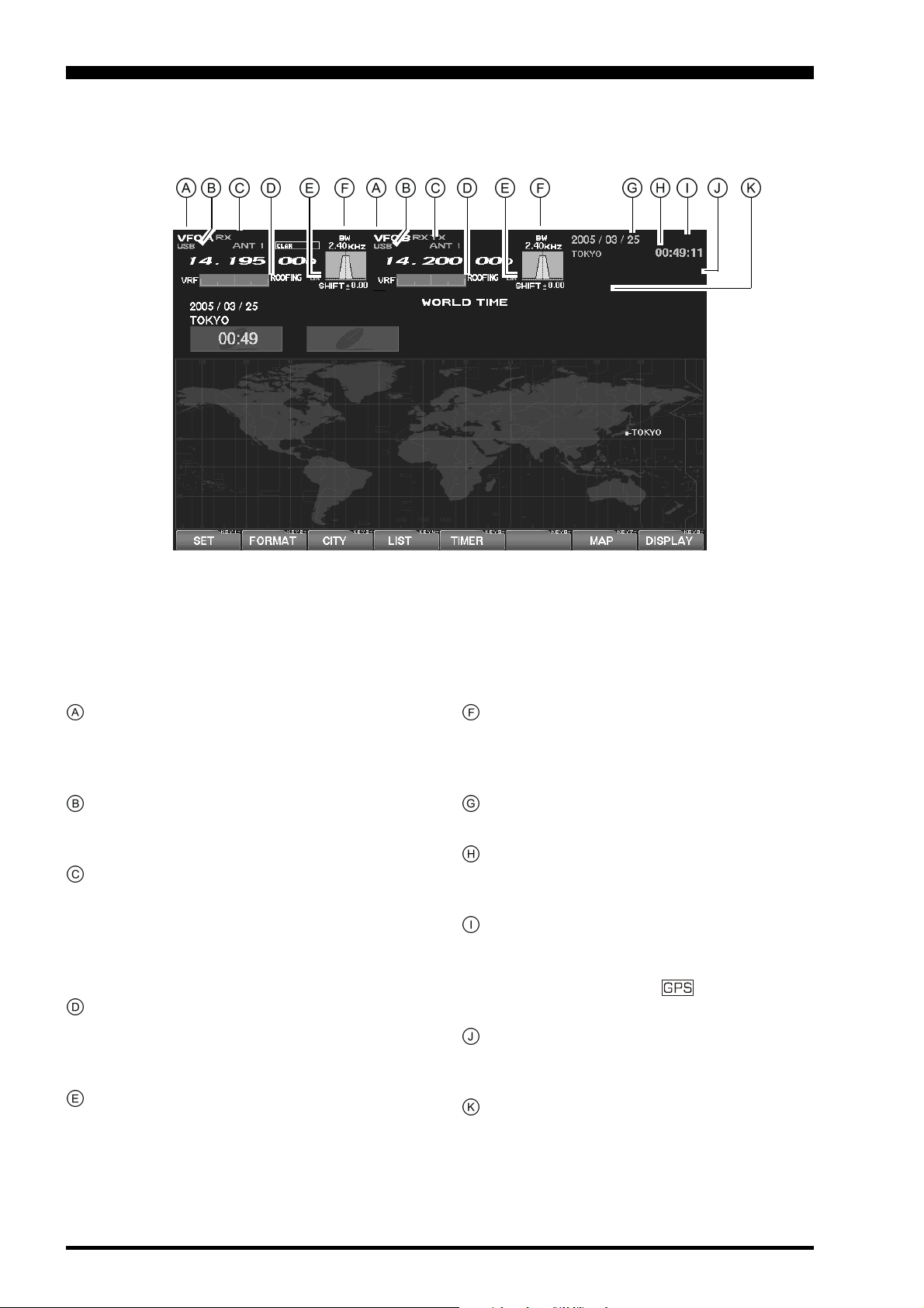
Main (VFO-A) & Sub (VFO-B) Fields
These areas of the TFT contain information about
the status of the Main (VFO-A) and Sub (VFO-B)
VFOs.
MODE Fields
These fields indicate the operating mode in use
on the above VFOs.
TX Frequency/Clarifier/
Antenna Selection Fields
These notations advise which VFO is being used
for transmission, status of the Clarifier, and a notation of which antenna has been selected on that
VFO.
Filter Fields
These fields note the offset status for the Tuning
or VRF filters, as well as the Roofing filter selection, for each VFO.
Filter Shift Fields
These fields graphically depict the positions of the
DSP RX filters for the Main and Sub VFOs, indicating any “IF Shift” or “Width” tuning changes
applied.
Bandwidth Fields
This field indicates the net receiver bandwidth currently set for the Main (VFO-A) and Sub (VFO-B)
VFOs.
Date Field
The current date is displayed here.
Local Time-1 Field
The current time at your location (Local Time-1)
is displayed here.
GPS Field
If you have connected an after-market GPS unit
(one providing NMEA location data) to the rear
panel of the transceiver, “ ” icon will appear
here.
Local Time-2 Field
The Local Time-2 time, as programmed, will appear here.
Timer Field
When the On Timer has been engaged, “TIMER”
will appear here; when the Alarm has been engaged, “ALARM” will appear in this field.
Page 4
FTDX9000 TFT OPERATION MANUAL
Page 7
BEFORE USING THE TFT DISPLAY
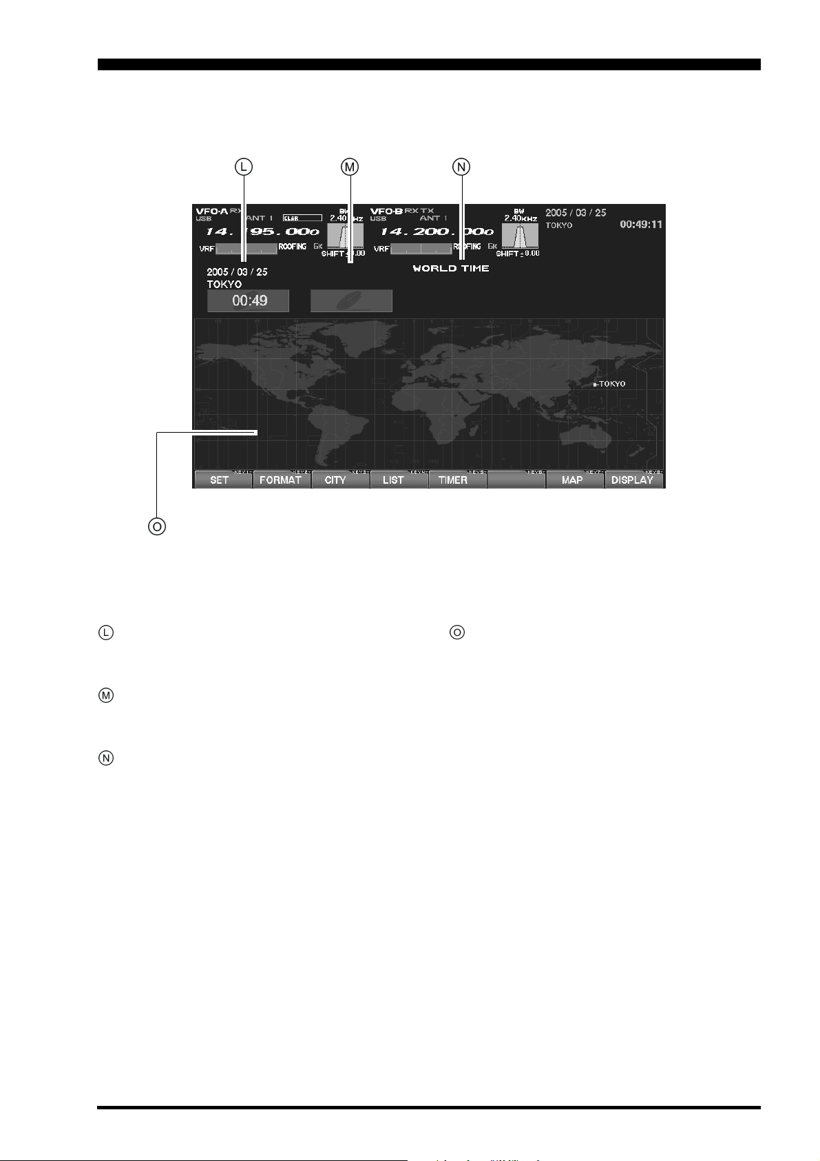
Local Time-1 Field
The current time at your location (Local Time-1)
is displayed here.
Local Time-2 Field
The Local Time-2 time, as programmed, will appear here.
World Time Field
This area shows the current time at the city selected on the World Map display.
TFT Display Pages
Individual pages are provided for a wide variety of
information or command purposes. Included are
the World Map page, Spectrum Scope page, Audio Scope/Oscilloscope page, TX PA Temperature/SWR page, Direction finding/Rotator Control
Page, Log Book Page, Memory Channel page,
and the Menu page.
FTDX9000 TFT OPERATION MANUAL
Page 5
Page 8

TABLE OF CONTENTS
Before Using the TFT Display ......................................................................................................................... 2
How to Use the World Clock function............................................................................................................ 7
About the World Clock .................................................................................................................................. 7
Explanation of the Function Keys on the World Map Screen ....................................................................... 7
SET (LOCAL-TIME1) Setup ......................................................................................................................... 8
FORMAT (TIME FORMAT) Setup ................................................................................................................ 8
City Selection 9
Miscellaneous World Clock Setup Options ................................................................................................. 10
OFF Timer and Alarm Setup ........................................................................................................................ 11
Spectrum Scope 12
About the Spectrum Scope ......................................................................................................................... 12
Explanation of the Function Keys on the Spectrum Scope Screen ............................................................ 12
Using the CTR (Center) Display Mode ....................................................................................................... 14
Using the LBWS (Limited Band Width Sweep) Function ............................................................................ 16
Using the FIX (Fixed) Mode ........................................................................................................................ 17
Audio Scope/Oscilloscope ............................................................................................................................ 18
About the Audio Scope/Oscilloscope .......................................................................................................... 18
Explanation of the Function Keys on the Audio Scope and Oscilloscope Screen ...................................... 18
Using the Audio Scope................................................................................................................................ 19
Audio Scope Specifications ........................................................................................................................ 19
Using the Oscilloscope ............................................................................................................................... 20
Oscilloscope Specifications ........................................................................................................................ 20
Log Book Function ........................................................................................................................................ 22
About the Log Book .................................................................................................................................... 22
Explanation of the Function Keys on the Log Book Screen ........................................................................ 22
Log Book Example ...................................................................................................................................... 23
CONFIG Setting .......................................................................................................................................... 24
CONFIG SETTING Mode Setup ................................................................................................................. 25
Log Book Data Input ................................................................................................................................... 26
Log Book Previous-QSO Check (CHECK) ................................................................................................. 27
Editing Log Book Entries............................................................................................................................. 27
Saving Log Book ......................................................................................................................................... 28
Loading Log Data (LOAD) .......................................................................................................................... 28
Summary Check ......................................................................................................................................... 29
Temperature/SWR Indication ........................................................................................................................ 30
About the Temperature/SWR Indication ..................................................................................................... 30
Explanation of the Function Keys on the Temperature/SWR Indication Screen......................................... 30
Graphic Meter Display ................................................................................................................................ 31
Swept SWR Display .................................................................................................................................... 31
Using the Marker on the SWR Graph ......................................................................................................... 32
Great Circle Map/Rotator Control Function ................................................................................................ 34
About the Great Circle Map/Rotator Control Function Screen.................................................................... 34
Explanation of the Function Keys on the Great Circle Map/Rotator Control Function Screen ................... 34
Manual Mode .............................................................................................................................................. 36
Preset Mode................................................................................................................................................ 37
Memory Mode ............................................................................................................................................. 38
Using the Memory Channel List ................................................................................................................... 39
About the Memory Channel List.................................................................................................................. 39
Explanation of the Function Keys on the Memory Channel List Screen ..................................................... 39
Erasing a Memory Channel/Restoring an Erased Memory Channel .......................................................... 40
Saving Memory Data .................................................................................................................................. 40
Loading Memory Data................................................................................................................................. 41
Using the MENU Mode .................................................................................................................................. 42
About the MENU Mode ............................................................................................................................... 42
Menu Mode Reset ................................................................................................................................. 42
Explanation of the Function Keys on the Menu Mode Screen .................................................................... 43
Memu Mode Configuration Changes .......................................................................................................... 44
Saving Menu Configuration Data ................................................................................................................ 45
Loading Menu Data ..................................................................................................................................... 46
Page 6
FTDX9000 TFT OPERATION MANUAL
Page 9
HOW TO USE THE WORLD CLOCK
ABOUT THE WORLD CLOCK
The World Clock displays the time in various coun-
tries, and the day/night areas are also indicated on
the map, including the Grey Line near the terminator.
The difference between the daylight areas in the
Southern and Northern Hemispheres is displayed
correctly, and is updated in real time. For DX hunt-
ing, this can be a very important and convenient tool
for specific long distance HF QSOs, for example, as
you can target the time the other station might have
access to, say, the 80-meter band, enabling you to
complete a QSO. In addition, an alarm is provided
which beeps with respect to a designated area at a
designated time, and the auto-off timer can also be
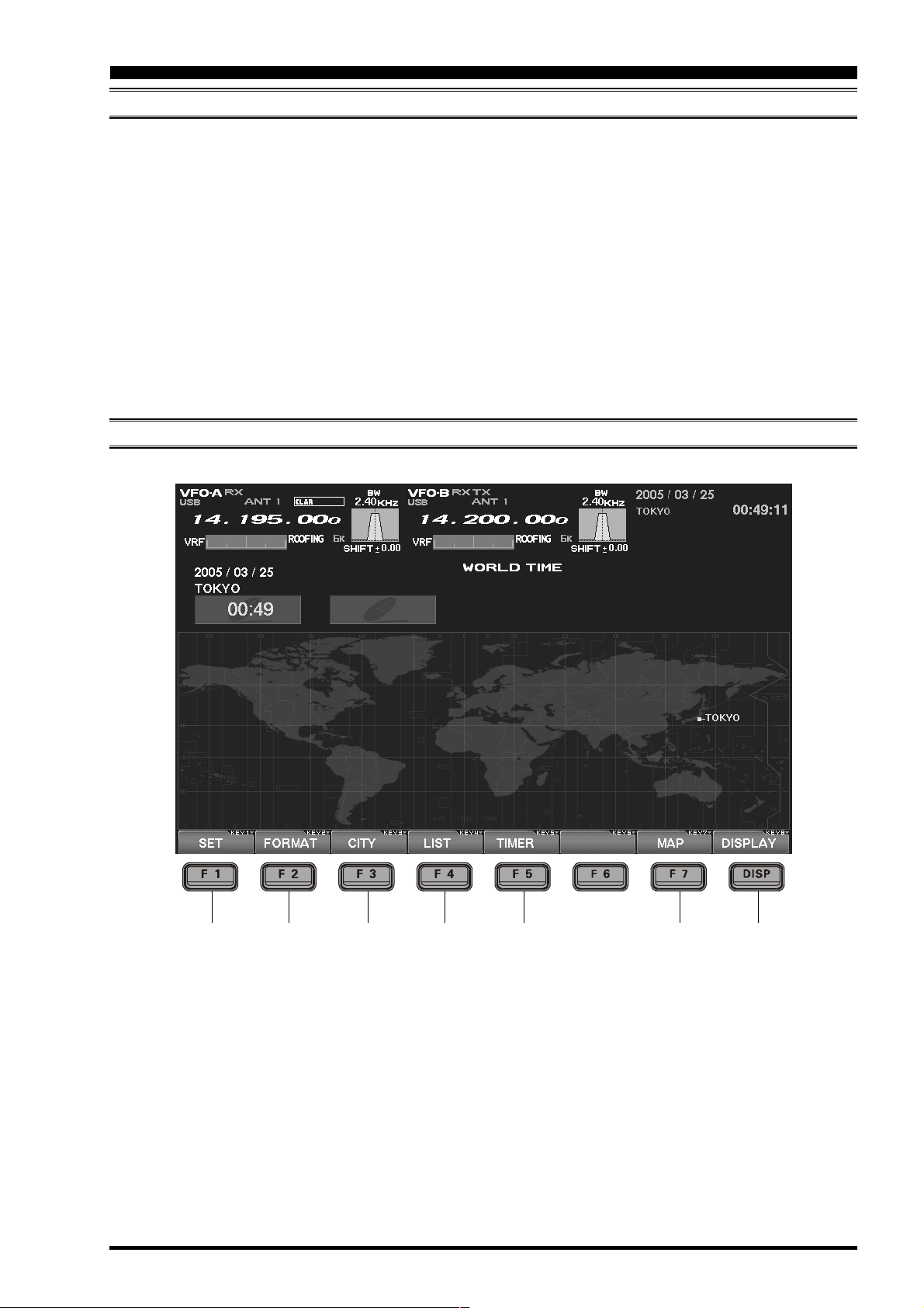
EXPLANATION OF THE FUNCTION KEYS ON THE WORLD MAP SCREEN
matched to any desired area you stipulate.
Note: When you turn on the transceiver for the first
time after your purchasing this radio, please set the
local time (the place where you operate this radio),
and confirm this setting. If this is not done, the various functions of the World clock and Great Circle
map will not function correctly. Regarding the setting
of the Local time, please see the “PLEASE READ
THIS FIRST” information.
If the World Map does not initially appear, press the
[
DISP](DISPLAY) key (momentarily) as many times
as necessary to display the World Map screen.
LIST
)
)
)
[F1](SET
Selects the LOCAL TIME-1 setup screen.
[F2](FORMAT
Selects 12-hour or 24-hour time format.
[F3](CITY
Selects the World Map for City selection.
[F4](
Displays the City setup list.
)
FTDX9000 TFT OPERATION MANUAL
[F5](
TIMER
Selects the TIMER setup screen.
[F7](
MAP
This lets you select between the World Map regular screen and the map that includes Daylight/
Darkness display.
[
DISP](DISPLAY
Press this key to switch the TFT to the “SPECTRUM
SCOPE” screen.
Press and hold in this key to switch the TFT to the
“MEMORY CHANNEL LIST” screen.
)
)
)
Page 7
Page 10
HOW TO USE THE WORLD CLOCK
SET (LOCAL-TIME1) SETUP
Please see the “PLEASE READ THIS FIRST” information.
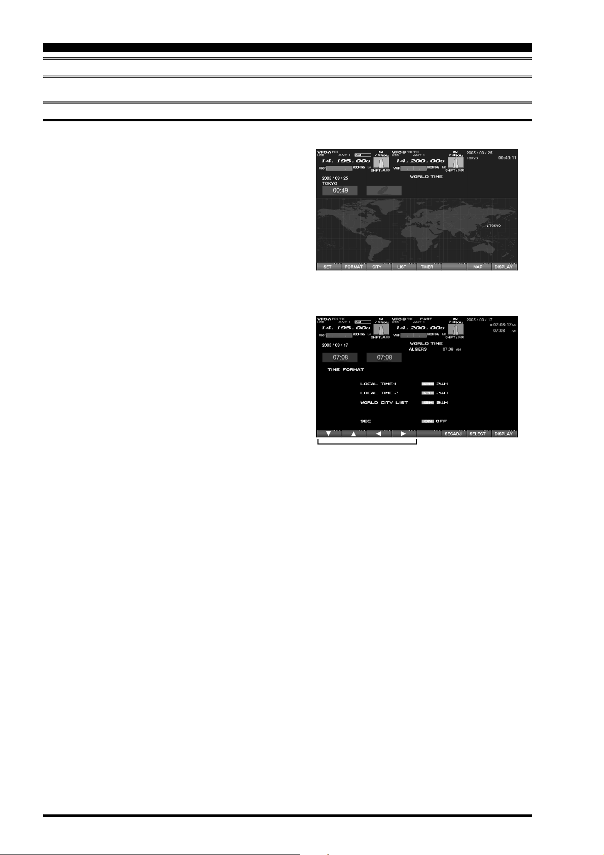
FORMAT (TIME FORMAT) SETUP
This procedure lets you choose between 12-hour and24-hour time display format.
1. While the World Map is displayed, press
[F2](
FORMAT) key to select TIME FORMAT.
2. Press the [F1](), [F2](), [F3](), [F4]() key,
and select 12-hour or 24-hour display for LOCALTIME1, CLOCAL-TIME2, and the WORLD CITY
LIST.
When SEC is set to “ON”, the “seconds” digits will
be shown at the top right corner of the TFT screen,
in the Local Time indication area.
Advice: If you press [F6](SECADJ) key, the “sec-
onds” indication will reset to “00.” Use this to sunc
your clock to a time standard such as WWV.
3. When all settings are complete, press and hold in
[F7](
SELECT) key for 2 seconds to exit.
“TIME FORMAT” Select
“SELECT” Keys
Set to “00” Second
FTDX9000 TFT OPERATION MANUALPage 8
Page 11
HOW TO USE THE WORLD CLOCK
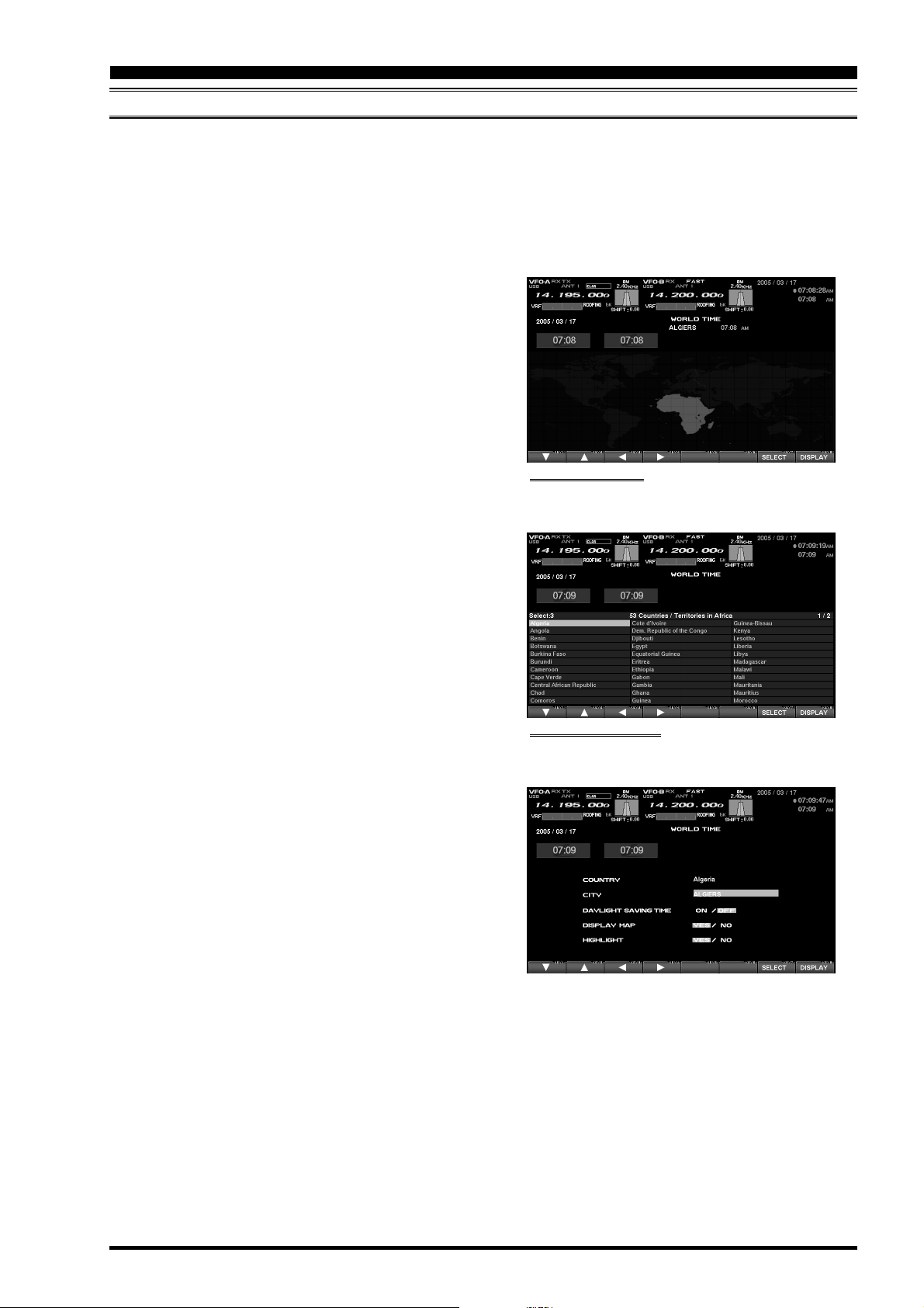
CITY SELECTION
It is possible to select any city name which is displayed on the World Clock screen.
Advice: The order of the display of the cities can be changed later; for now, please just select one of the supplied
city names.
There may only be one city shown in some countries; however, it is possible to add cities, if desired.
If you wish to add a city to the City List that was programmed at the factory, you will need to supply your own USB
or PS/2 Keyboard. If you utilize one of the pre-loaded cities, a keyboard is not necessary.
1. Press the [F3](CITY) key while the World Map is
displayed, and the TFT will show the “Area Selection” screen.
2. Press the [F1](), [F2](), [F3](), [F4]() keys
to select the time zone in which the desired city is
located.
3. Confirm that the desired area is highlighted, and
press the [F7](SELECT) key momentarily. Now
the country list for the selected zone will be displayed.
4. Use the [F1](), [F2](), [F3](), [F4]() keys
to select the desired country in this area.
5. Now press the [F7](SELECT) key momentarily,
and you will see the list of the city names in the
country selected.
6. Press the [F1](), [F2](), [F3](), [F4]() key
to select the desired city. Even if the city displayed
is the only one in the country, select it anyway.
7. Once you have pressed the [F7](SELECT) key
momentarily, the selected country name and the
city name will be indicated, thanks to the procedure mentioned above. If you want to input a city
name which is not in the list, press the
[F7](
SELECT) key after confirming that the city
name is highlighted. Then, enter the city name
you want.
8. Press the [F1](), [F2](), [F3](), [F4]() key
to set DAYLIGHT SAVING TIME (Summer Time),
DISPLAY MAP (display or not display city names
on the World Clock screen), or HIGHLIGHT (select highlighted indication (yellow) or normal
(white) indication).
9. When finished, press and hold in the
[F7](
SELECT) key for 2 seconds to exit.
“AREA SELECTION” SCREEN
“COUNTRY SELECTION” SCREEN
FTDX9000 TFT OPERATION MANUAL Page 9
Page 12
HOW TO USE THE WORLD CLOCK
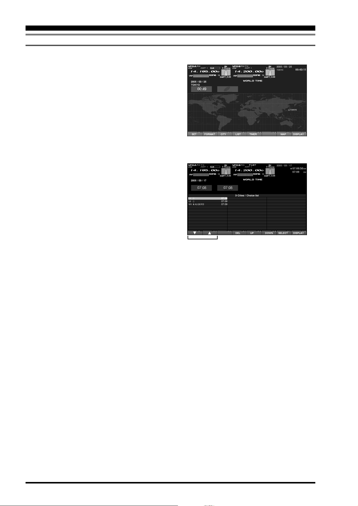
MISCELLANEOUS WORLD CLOCK SETUP OPTIONS
It is possible to change the order of selection of the city times, as well as the display color, etc.
1. On the World Map Screen, press the [F4](LIST
key to select the “City Name List” screen.
2. If you want to change the order of the city times
as indicated at the middle of the TFT screen, press
the [F1]() or [F2]() keys to move the cursor to
the city name you want to change the position of.
When the [F6](DOWN) key is pressed, the position goes downward. If you need to move it further, repeat as necessary.
3. If you want to change other settings of a city, select the city name by pressing the [F1](q) or [F2](p)
keys to highlight the city, then press the
[F7](
SELECT) key momentarily. Now the screen
will change to the city setup screen, where the
following settings can be done: DAYLIGHT SAVING TIME (to select Summer time), DISPLAY MAP
(display or not display city names on the World
Clock screen), and HIGHLIGHT (select yellow or
white highlighting indication for cities).
4. If you want to delete a city from the World Clock
screen, move the cursor to the city name by pressing the [F1]() or [F2]() keys , then press the
[F4](
DEL) key.
5. When finished, press and hold in [F7](SELECT
for 2 seconds to exit.
)
“LIST” Select
)
“SELECT” Keys
“DELETE” Key
Advice: On the DISPLAY MAP setting, if the city name
indication is selected, the city name will be displayed
on the World Map. When “NO” is selected, the city
name will not be displayed, and only the city name
and the current time is indicated at the middle of the
TFT screen.
For the HIGHLIGHT setting (city name: highlighted
or not highlighted), if “Highlight” (YES) is selected,
the city name on the world map will be shown in yellow font color.
If “NOT Highlighted” (NO) is selected, the city name
will be indicated in white.
FTDX9000 TFT OPERATION MANUALPage 10
Page 13
HOW TO USE THE WORLD CLOCK
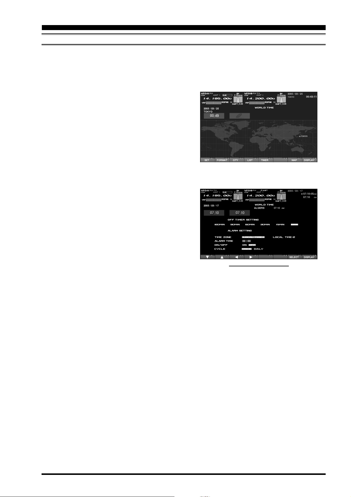
OFF TIMER AND ALARM SETUP
It is easy to set the OFF Timer and Alarm times.
As to the OFF TIMEER, countdown intervals of 120/90/60/30/15 minutes, and OFF, can be selected.
For the alarm setting, it is possible to choose either LOCAL-TIME1 or LOCAL-TIME2, set the alarm time, set the
Alarm ON or OFF, and/or sound the alarm one time only or every day.
1. On the World Map screen, press the [F5](TIMER
key to move to the OFF TIMER and ALARM setup
screen.
2. Press the [F1](), [F2](), [F3](), [F4]() key
to move the cursor to the desired setup item; the
selected item will be highlighted.
OFF TIMER setup:
120/90/60/30/15 minutes, and OFF
ALARM setup:
(When setting up the Alarm, be sure to set the
OFF TIMER setting to OFF!)
TIME ZONE (LOCAL TIME-1/LOCAL TIME-2)
ALARM TIME
ALARM ON/OFF
CYCLE (ONCE/DAILY)
3. Press and hold in [F7](SELECT) key for 2 sec-
onds to close and exit.
Advice: When the OFF timer is engaged (power is
shut off), the condition of the radio is the same as if
the power switch on the front panel has been turned
off. The Main power (circuit breaker) is not turned
off. Therefore, power to the OCXO will be Maintained,
retaining the high frequency stability.
)
“TIMER” Select
OFF TIMER AND ALARM SETUP PAGE
The Alarm will ring for around 60 seconds. If you want
to stop the alarm, press any of the keys located on
the front panel.
FTDX9000 TFT OPERATION MANUAL Page 11
Page 14
SPECTRUM SCOPE
ABOUT THE SPECTRUM SCOPE
This page displays the Spectrum Scope which is convenient for monitoring band activity.
The entire screen will become the spectrum display,
and you can see both strong and weak signals clearly
and easily. Not only the Main (VFO-A) is shown, but
the spectrum of the Sub (VFO-B) side can be also
switched in and displayed simultaneously.
Besides simultaneous display of the Main (VFO-A)
and Sub (VFO-B) spectra, the LBWS function allow
you to realize very high-speed signal detection over
a limited band segment. The CTR mode let you monitor close by your current frequency (your frequency
is located at the center of the screen), and the FIX
mode can also be engaged, whereby the left edge
frequency is fixed. These features have been carefully considered for their utility in actual Amateur Ra-
dio operation.
If the Spectrum Scope is not currently displayed, press
the [DISP](DISPLAY) key momentarily as many times
as needed to bring up the Spectrum Scope display
screen.
Advice: The Spectrum Scope function of the
FTDX9000 is a very intelligent capability, and it includes
a wide array functions; if you lose your way during
operation of this function, press the [DISP](DISPLAY
key momentarily to change the screen, and then return again to the Spectrum Scope screen.
Quick Point: The vertical axis of the Spectrum Scope
is 10 dB per division.
During transmission, the transmitter’s waveform will
be displayed.
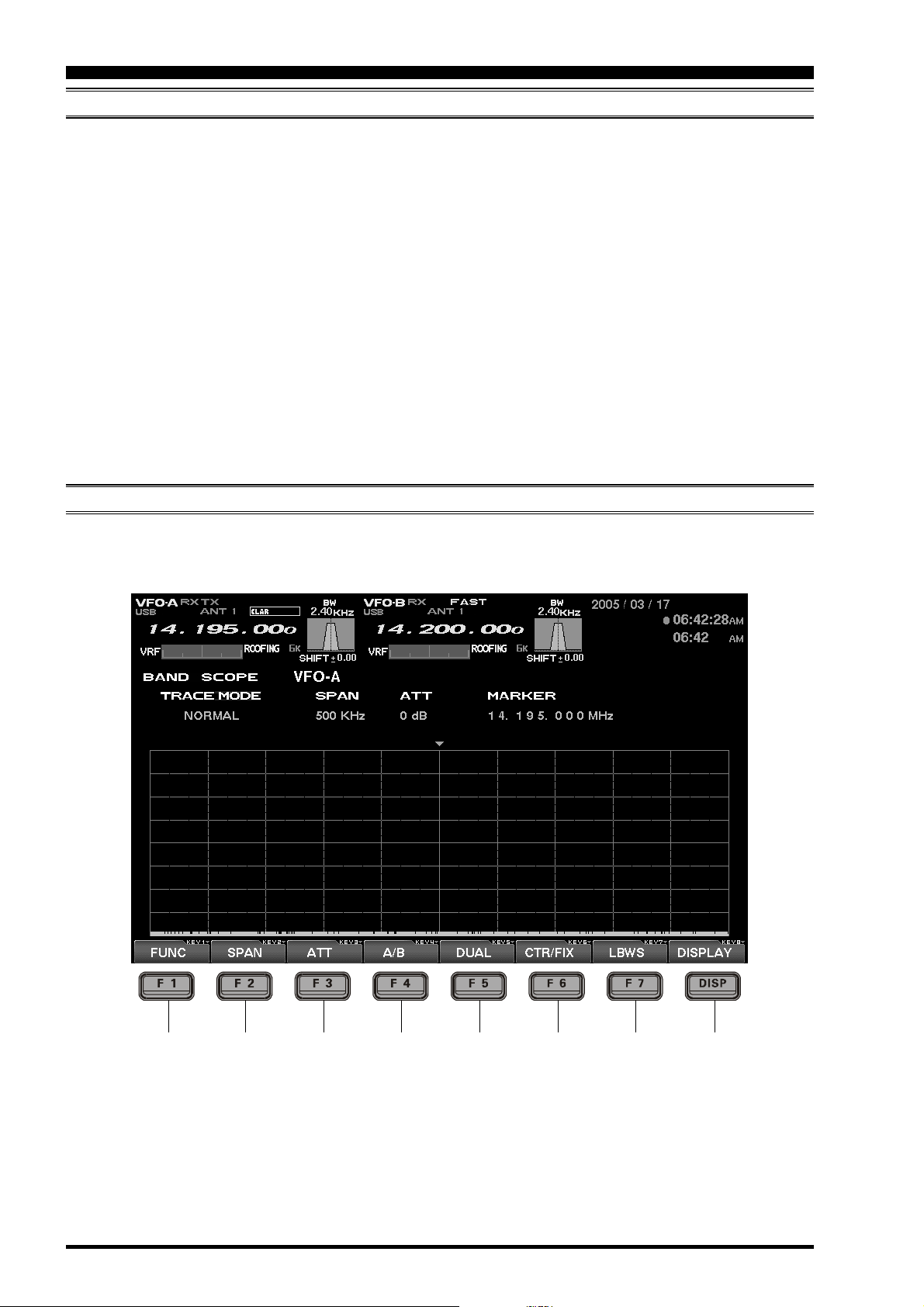
EXPLANATION OF THE FUNCTION KEYS ON THE SPECTRUM SCOPE SCREEN
Below you will find the explanation of the function keys utilized while the Spectrum Scope is displayed. Depending on the individual screen in use, the functions of the function keys located just below the TFT screen varies.
Please confirm the function displayed on the screen during operation.
)
[F1](FUNC
Moves you to the function screen of the Spectrum
Scope used for setup of the MKR (Marker) function, etc.
Advice: On this screen, the functions assigned
to the function keys can be changed. If you want
to go back to the previous screen, press the
[F7](
EXIT) key.
)
Page 12
[F2](
SPAN) “Bandwidth”
By pressing this key momentarily, it is possible to
set the range of frequencies from the left edge to
the right edge. If the setting is toggled to 2500
kHz, and you press this key once more, the span
returns to 25 kHz again. At the top of the screen,
the current span is indicated below the span indication.
FTDX9000 TFT OPERATION MANUAL
Page 15

SPECTRUM SCOPE
EXPLANATION OF THE FUNCTION KEYS ON THE SPECTRUM SCOPE SCREEN
25 kHz
500 kHz
[F3](ATT) “Attenuator”
By pressing this key, the attenuation can be
switched as shown below. The noise level on the
band will vary according to conditions, your antenna, the time of day, etc.; please select the appropriate value for current conditions.
0 dB
10 dB
[F4](
Selects the VFO which is to be shown.
In the case of “Single” display, the Main (VFO-A)
and Sub (VFO-B) VFOs can be toggled alternately.
In the “Dual” mode, both VFOs will be shown.
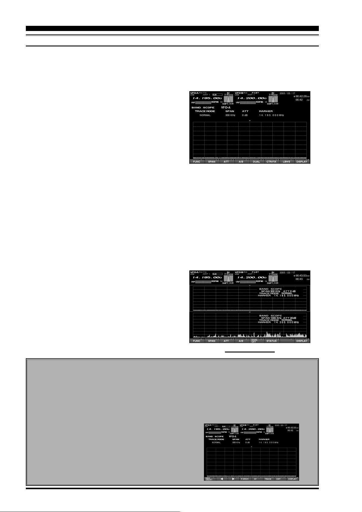
[F5](
This key switches between Single and Dual VFO
Spectrum Scope display. When Dual is selected,
the Main VFO will occupy the upper position, and
the Sub VFO the lower.
When this key is pressed once more, the radio
will revert to “Single” display. If you want to change
the setup of a Spectrum Scope VFO, press the
[F4](
the upper side or lower side. Select the side which
you want to change, then press the [F3](ATT) key
or the [F2](SPAN) key to change those respective settings just for the selected VFO.
In the Dual display mode, when you want to confirm the setup situation, press the [F6](STATUS
key to show the current settings for that screen.
Press the key once again to make the setup
screen disappear.
)
A/B
DUAL
A/B) key. In this case, the frame will move to
50 kHz
1000 kHz
)
100 kHz
20 dB
2500 kHz
0 dB ......
250 kHz
25 kHz ......
[F6](
)
CTR/FIX
By pressing this key, it is possible to switch between the CTR mode and FIX mode.
In the CTR mode, the current operating frequency
is displayed at the center of the screen; in the FIX
mode, the frequency selected via the Menu is fixed
at the left edge of the display.
Advice: In either CTR or the FIX mode, the current operating frequency is indicated on the screen
by the yellow arrow (), for ease of status recognition.
[F7](
LBWS
Press this key to activate the “Limited Band Width
Sweep” (LBWS) function, which permits highspeed sweeping of a band segment.
As the bandwidth is set narrower, the sweep speed
becomes faster, allowing the scope to capture signals with quicker resolution. The bandwidth can
be set to 50 %, 30 % or 10 % of the full span. The
sweep speed becomes faster by the following
amounts:
50 %: about 2 times faster
30 %: about 3 times faster
10 %: about 10 times faster
NORMAL
LBWS-2(30%
Advice: When you enter the LBWS mode, the
function keys below the TFT display change.
It is possible to move the sweep position by pressing the [F5]() and [F6]() key.
If you want to return to normal operation, press
[F6](
LBWS) key as needed.
Please note that LBWS can not be used in the
FIX mode. Please use LBWS only in the CTR
mode.
)
)
LBWS-1(50%
)
)
LBWS-3(10%
)
NORMAL ......
FIX MODE SETUP (LEFT EDGE FREQUENCY
Press the [MNU] key momentarily to enter the Menu
mode. Select the item which you want to change
by rotating the Main Tuning knob (in this case, the
item will be one of the items in the range from
SCOPE “108: MAIN FIX 1.8 MHz” to “129: SUB
FIX 50MHz”). Then change the setting by rotating
the CLAR/VFO-B knob.
When the change is completed, press and hold
in the [MNU] key for 2 seconds to save the change.
FTDX9000 TFT OPERATION MANUAL
[
DISP](DISPLAY
Press this key to switch the TFT to the “AUDIO
SCOPE/OSCILLOSCOPE” screen.
Press and hold in this key to switch the TFT to the
“WORLD CLOCK” screen.
)
)
If you do not want to save the change, press the
[MNU] key momentarily. The radio will go back to
the previous condition/situation.
There are many setup items in the Menu mode,
and they are grouped for easy recognition; the group
name is displayed at the top left corner of the list
screen. It is usually more convenient if you initially
select the group by rotating the Main Dial, and then
select the item you want.
Page 13
Page 16
SPECTRUM SCOPE
USING THE CTR (CENTER
It is possible to switch between the Main (VFO-A) and Sub (VFO-B) VFOs. Also, dual display of both VFOs is
available (Upper: Main (VFO-A) and Lower: Sub (VFO-B)).
Also, the LBWS (Limited Band Width Sweep) mode lets you perform a high-speed, high-resolution sweep of a
limited band segment.
1. Press the [F6](CTR/FIX) key to change to the CTR
mode.
2. By pressing [F6](CTR/FIX) key, the CTR mode
and the FIX mode will be toggled alternately. In
the CTR mode, the center frequency (your current operating frequency) will displayed and the
frequency indication located at the mid of the display will be shown as FREQUENCY. Also, the
yellow “” arrow will appear at the center of the
display, indicating your current operating frequency.
3. Press the [F2](SPAN) key to select the desired
frequency span to monitor.
By pressing the [F2](SPAN) key, the span will
change as follows.
25 kHz
500 kHz
4. Press this key to select the attenuation value according to current propagation conditions, your
operating frequency and antenna, etc.
0 dB
10 dB
5. Press the [F4](A/B) key to select the desired VFO
to monitor.
6. If you want to display both VFO spectra, press
the [F5](DUAL) key to engage the dual display
mode.
The Main (VFO-A) will appear in the upper display field, and the Sub (VFO-B) will appear in the
lower. When dual display is engaged, if the
[F6](
STATUS) key is pressed, the setup status will
be indicated on the screen. When this key is
pressed again, the setup status screen will disappear.
50 kHz
1000 kHz
100 kHz
20 dB
2500 kHz
0 dB ......
250 kHz
25 kHz ......
)
ISPLAY MODE
D
“SPAN” Select
“FIX/CRT” Select
DUAL DISPLAY MODE
USING THE MARKER
Press the [F1](FUNC) key to show the screen
for setup of the Marker. The indication
[F1](
FUNC) will change to [F1](MKR ON/OFF);
now press [F1](MKR ON/OFF) once again, and
the Marker line will be displayed at the center of
the screen.
It is possible to change the position of the marker
by pressing the [F2]() and [F3]() key. If you
want to center on a strong signal, you can move
the marker to the screen position occupied by
that signal. When the [F5](CF) key is pressed
momentarily (one touch), the marker position
will return to the center.
Page 14
In order to remove the marker, press the
[F1](
MKR ON/OFF) key.
When you want to return to the Spectrum Scope
screen, press the [F7](EXIT) key. If the screen
returns to the previous screen (with the Marker
displayed), the marker will remain on the screen.
FTDX9000 TFT OPERATION MANUAL
Page 17

SPECTRUM SCOPE
USING THE CTR (CENTER
Miscellaneous Functions
SEARCHING FOR STRONG SIGNALS
USING THE PEAK SEARCH FEATURE
1. Press the [F1](FUNC) key to show the screen for
setup of the Marker.
2. Press the [F4](P.SRCH) key to move the marker
to the highest peak signal frequency. With each
press the [F4](P.SRCH) key, the Marker will shift
to the strongest signal frequency away from the
current frequency.
CHANGING THE TRACE MODE
1. Press the [F1](FUNC) key to show the screen for
setup of the Marker.
2. Press the [F6](TRACE) key to select the Trace
mode of the Spectrum Scope.
The Trace mode selections are shown below.
NORMAL
NORMAL: The real-time signal strength will
AVERAGE: The averaged signal strength will
PEAK HOLD P: The signal level will be displayed,
AVERAGE
be displayed. Normally, you will
want to use this mode.
be displayed.
with peak strengths held for a
few seconds.
PEAK HOLD P
NORMAL ......
)
ISPLAY MODE
D
“PEAK SERCH” mode
“TRACE” mode
FTDX9000 TFT OPERATION MANUAL
Page 15
Page 18

SPECTRUM SCOPE
USING THE LBWS (LIMITED BAND WIDTH SWEEP
LBWS (Limited Band Width Sweep) is a function that sweeps a limited segment of the Spectrum Scope span
without changing the span (bandwidth). As the sweep segment becomes narrower, the speed becomes faster,
and the accuracy and resolution become enhanced.
The bandwidth can be set to 50 %, 30 %, or 10 % of the full span. The sweep speed will increase as follows:
50 %: about 2 times faster, 30 %: about 3 times faster, 10 %: about 10 times faster
1. By pressing the [F7](CTR/FIX) key repeatedly, the
CTR mode and the FIX mode will be toggled alternately.
2. By pressing the [F2](SPAN) key, you can set the
bandwidth of the span viewed using the Spectrum
Scope.
By pressing the [F2](SPAN) key, the span will
change as follows.
25 kHz
500 kHz
3. Press the [F3](ATT) key to set the desired attenu-
ation value.
By pressing the [F3](ATT) key, the attenuation will
change as follows.
0 dB
10 dB
4. By pressing the [F6](LBWS) key, the LBWS seg-
ment width will change as follows.
NORMAL
LBWS-2(30%
5. Press the [F4](A/B) key to select the Main (VFO-
A) or Sub (VFO-B) VFO.
50 kHz
1000 kHz
20 dB
LBWS-1(50%
)
LBWS-3(10%
100 kHz
2500 kHz
0 dB ......
)
250 kHz
)
25 kHz ......
NORMAL ......
)
UNCTION
F
“FIX/CRT” Select
Advice:Please note that the LBWS feature can not
be used in the FIX mode. Please use LBWS only in
the CTR mode.
While LBWS is engaged, it is not possible to switch
to the dual display mode.
“LBWS WIDTH” Select
Page 16
FTDX9000 TFT OPERATION MANUAL
Page 19

SPECTRUM SCOPE
USING THE FIX (FIXED
This feature is convenient when you want to monitor an entire amateur band.
The starting point, located at the left edge of the screen, can be set via the Menu. Even if the screen span
(bandwidth) is changed, the start frequency will not be changed. By watching the screen, you can move your
operation to frequencies where interesting activity appears on the display. Just as with the CTR mode, it is
possible to toggle the Main (VFO-A) or Sub (VFO-B) VFOs. It is also possible to utilize a dual display, with the
Main (VFO-A) VFO in the upper position, and the Sub (VFO-B) VFO below.
1. By pressing the [F7](CTR/FIX) key, it is possible
to switch between the CTR mode and the FIX
mode. Select the CTR mode at this time.
2. Press the [F2](SPAN) key to set the desired value
for the Span (bandwidth). By pressing the
[F2](
SPAN) key, the span will change as follows.
25 kHz
500 kHz
3. Press the [F3](ATT) key to set the desired attenu-
ation value. By pressing the [F3](ATT) key, the
attenuation will change as follows.
0 dB
10 dB
4. Press the [F4](A/B) key to toggle between the Main
(VFO-A) and Sub (VFO-B) VFOs.
5. Press the [F5](DUAL) key to engage dual spec-
tral display.
The Main VFO will appear in the upper display
field, and the Sub VFO will appear in the lower.
When you rotate the Main Tuning knob for Main
(VFO-A) or CLAR/VFO-B knob for Sub (VFO-B),
the yellow arrow “” will move to follow your receive frequency.
If the receive frequency is outside of the screen,
the position of the operating frequency will be
“shown” in the lower area of the display as “<<” “>>”,
and “RCV Freq is out of range” will also be displayed.
6. Just as in the CTR mode, you can use the Marker.
Please see page 14 for information on using the
marker.
50 kHz
1000 kHz
100 kHz
20 dB
2500 kHz
0 dB ......
250 kHz
25 kHz ......
)
ODE
M
“SPAN” Select“ATT” Select“FIX/CRT” Select
Advice: In either CTR or FIX mode, the current operating frequency will be indicated on the screen by
the yellow arrow “.”
SETTING THE LEFT EDGE FREQUENCY FOR THE FIX MODE
Press the [MNU] key momentarily to enter the Menu
mode. Select the item which you want to change
by rotating the Main dial (in this case, the items will
be in the range from SCOPE “107: MAIN FIX 1.8
MHz
” to “128: SUB FIX 50MHz”). Now you may
change the setting by rotating the Sub dial.
When the change(s) are completed, press and hold
in the [MNU] key for 2 seconds to save the change.
FTDX9000 TFT OPERATION MANUAL
If you do not want to save the change(s), press the
[MNU] key momentarily. The radio will go back to
its previous condition/situation.
There are many setup items in the Menu, and they
are grouped; the group name is displayed at the
top left area of the list screen. It will generally be
more convenient for you if you initially select the
group, by rotating the Main Dial, and then select
the item you want to work on.
Page 17
Page 20

AUDIO SCOPE AND OSCILLOSCOPE
ABOUT THE AUDIO SCOPE AND OSCILLOSCOPE
It is possible to show both the Audio Scope and the Oscilloscope displays simultaneously.
With the Audio scope, the horizontal line represents frequency, and you can use this function check the frequency response within the TX bandwidth. In the Oscilloscope mode, the horizontal line represents time, and
you can check the RX signal waveform within the RX bandwidth, as well as the TX wave form.
E
XPLANATION OF THE FUNCTION KEYS ON THE AUDIO SCOPE AND OSCILLOSCOPE SCREEN
Here are the uses for the function keys when the Audio scope and Oscilloscope are displayed on the screen.
VFO-B
10 dB
)
WF-1
)
WF-2
EXT
20 dB
VFO-A ......
0 dB ......
NORMAL ......
[F2](MODE
The SCAN MODE for the left-side Audio Scope
can be changed. By pressing this key, the mode
changes as shown below.
NORMAL
WF-1 and WF-2 are “Waterfall” displays. The
sweep time (speed) of WF-2 is faster than that of
WF-1.
[F3](
SOURCE
Pressing this key lets you select the source for
the audio to be viewed by the Audio Scope. The
selections are:
VFO-A
When EXT is selected, you can observe the audio wave form of a signal provided by equipment
connected to the AUDIO IN jack on the rear panel
of the transceiver.
[F4](ATT) “Attenuator”
This key lets you adjust the attenuator for the Audio scope. Set the appropriate value based on the
received signal.
0 dB
[F6](
LEVEL
This key lets you adjust the sensitivity of the Oscilloscope display at the right side of the screen.
Adjust the level while viewing the screen, to optimize the setting for the lighting conditions in your
station. Available values are:
0.3 V
[F7](
SWEEP
This key lets you adjust the sweep time for the
Oscilloscope. Adjust this setting while viewing the
screen. Available sweep times are:
10 ms
[
DISP](DISPLAY
Press this key to switch the TFT monitor to the
“LOG BOOK” screen.
Press and hold in this key top switch the TFT to
the “SPECTRUM SCOPE” screen.
0.1 V
30 ms
)
)
1.0 V
100 ms
)
0.3 V ......
300 ms
1 s
10 ms ......
Page 18
FTDX9000 TFT OPERATION MANUAL
Page 21

AUDIO SCOPE AND OSCILLOSCOPE
USING THE AUDIO SCOPE
The Audio Scope is particularly useful when making adjustments to the transmitter, especially when setting up
the Speech Processor as well as the Parametric Microphone Equalizer.
On receive, you can observe the signal characteristics and quality of the incoming signal, as well. In the case of
the Waterfall display, this can be used for precise frequency alignment of incoming signals to correspond with
filters used in your computer’s sound card or modem. The sweep time (speed) of WF-2 is faster than WF-1, and
you can choose the sweep most appropriate for your operating application.
1. By pressing the [F2](MODE) key, the Waterfall
mode can be modified. The available selections
are:
VFO-B
0.1 V
NORMAL
NORMAL is a regular spectrum display.
WF-1 and WF-2 are Waterfall displays, with WF2 utilizing a faster sweep time than the WF-1 selection.
2. Pressing the [F3](SOURCE) key lets you select
the source for the audio to be viewed by the Audio
Scope. The selections are:
VFO-A
Advice: When EXT is selected, you can observe
the audio wave form of a signal provided by equipment connected to the AUDIO IN jack on the rear
panel of the transceiver.
3. Press the [F4](ATT) key to change the setting for
the attenuator. The available settings are:
0.3 V
WF-1
1.0 V
EXT
WF-2
0.3 V ......
NORMAL ......
VFO-A ......
SPECTRUM DISPLAY
Advice: By using this feature, you can conveniently
monitor the status of the CONTOUR filter, the performance of the IF Notch, and the WIDTH/SHIFT status.
AUDIO SCOPE SPECIFICATIONS
Frequency Range: 100 Hz - 4 kHz
Frequency Resolution: 20 Hz (Approx.)
Display Range: 80dB (Approx.)
Signal Processing: FFT
Input Level: 1 Vp-p Input (ADC Max. value)
Attenuator: @0 dB, top edge;
@10 dB, 1 division of shift;
@20 dB, 2 divisions of shift
(Fast Fourier Transformation)
WATERFALL DISPLAY
FTDX9000 TFT OPERATION MANUAL
Page 19
Page 22

AUDIO SCOPE AND OSCILLOSCOPE
USING THE OSCILLOSCOPE
Both TX and RX waveforms can be observed, allowing optimal adjustments pf setup options or filter settings, on
Voice, CW, and Digital modes.
1. Press the [F6](LEVEL) key to set the level as ap-
propriate for the signal strength being monitored.
Available values are:
0.3 V
2. Press the [F7](SWEEP) key to set the desired
sweep time. Available values are:
10 ms
0.1 V
30 ms
1.0 V
100 ms
0.3 V ......
300 ms
1 s
10 ms ......
Advice: When monitor the TX waveform, turn on the
monitor feature by pressing the front panels [MONI
key.
]
OSCILLOSCOPE SPECIFICATIONS
Frequency Range: 0 - 4 kHz
Sweep Speed: 10/30/100/300/1000ms (adjustable)
Time Base Indication: One frame: 10 divisions (20 gradations) “Sweep time / 20”
500 µ/1.5 m/5 m/15 m/50 m/DIV
Signal Processing: AC Level Detection Synchronizer function
Input Level: 1 Vp-p Input (ADC Max. value)
Page 20
FTDX9000 TFT OPERATION MANUAL
Page 23

AUDIO SCOPE AND OSCILLOSCOPE
NOTE
FTDX9000 TFT OPERATION MANUAL
Page 21
Page 24

LOG BOOK FUNCTION
ABOUT THE LOG BOOK
By connecting your keyboard (not supplied) to the transceiver’s rear-panel KEYBOARD jack (PS/2 or USB), you
can create a Log Book within the radio, and display it on the TFT. Date, time, frequency, and mode will be
automatically stored, and you can save log data to the Compact Flash card for archive purposes.
EXPLANATION OF THE FUNCTION KEYS ON THE LOG BOOK SCREEN
[F1](FUNC
You may use the “CHECK” function to check the
log to see if a QSO has been made previously
with the logged station, and you may also create
a summary of QSOs by band and mode by pressing this key. The log may be viewed solely for the
current operator, or for all operators registered into
the Logbook and saved on the CF card.
[F2]()
Press this key to shift to the log line below the
current one.
[F3](
Press this key to shift to the log line above the
current one.
)
)
[F4](
Press this key to enable editing of previouslystored log data.
[F7](
Press this key to engage the screen that allows
you to manage log data to be saved.
[
DISP](DISPLAY
Press this key momentarily to move to the “TEM-
PERATURE/SWR INDICATION” screen.
Press this key for 2 seconds to move to the “AU-
DIO SCOPE/OSCILLOSCOPE” screen.
)
EDIT
SAVE/LOAD
)
)
Page 22
FTDX9000 TFT OPERATION MANUAL
Page 25
LOG BOOK FUNCTION
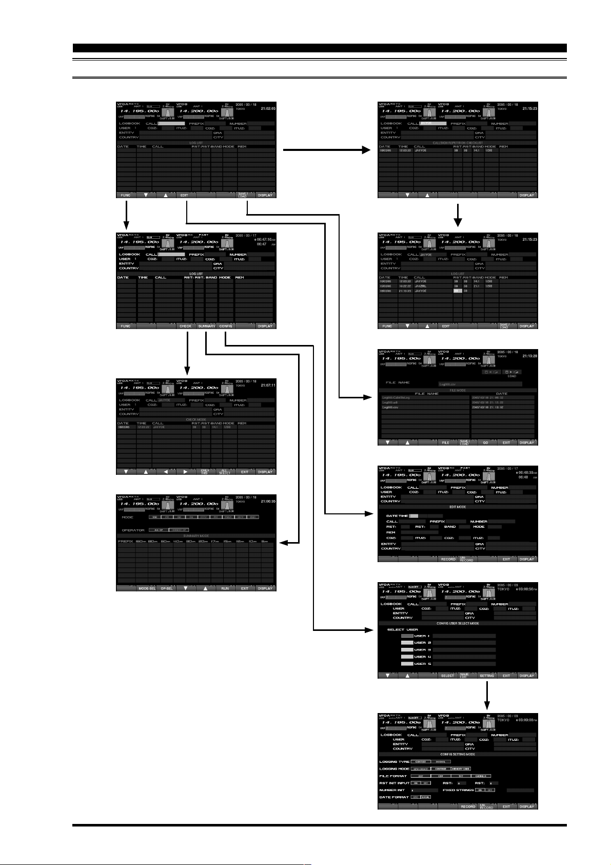
LOG BOOK EXAMPLE
[F1](
[F4](
FUNC
CHECK
Enter key
)
[F4](
EDIT
)[F7](
SAVE/LOAD
)
Enter key
)
[F5](
SUMMARY
[F6](
CONFIG
)
)
[F6](
SETTING
)
FTDX9000 TFT OPERATION MANUAL
Page 23
Page 26
LOG BOOK FUNCTION
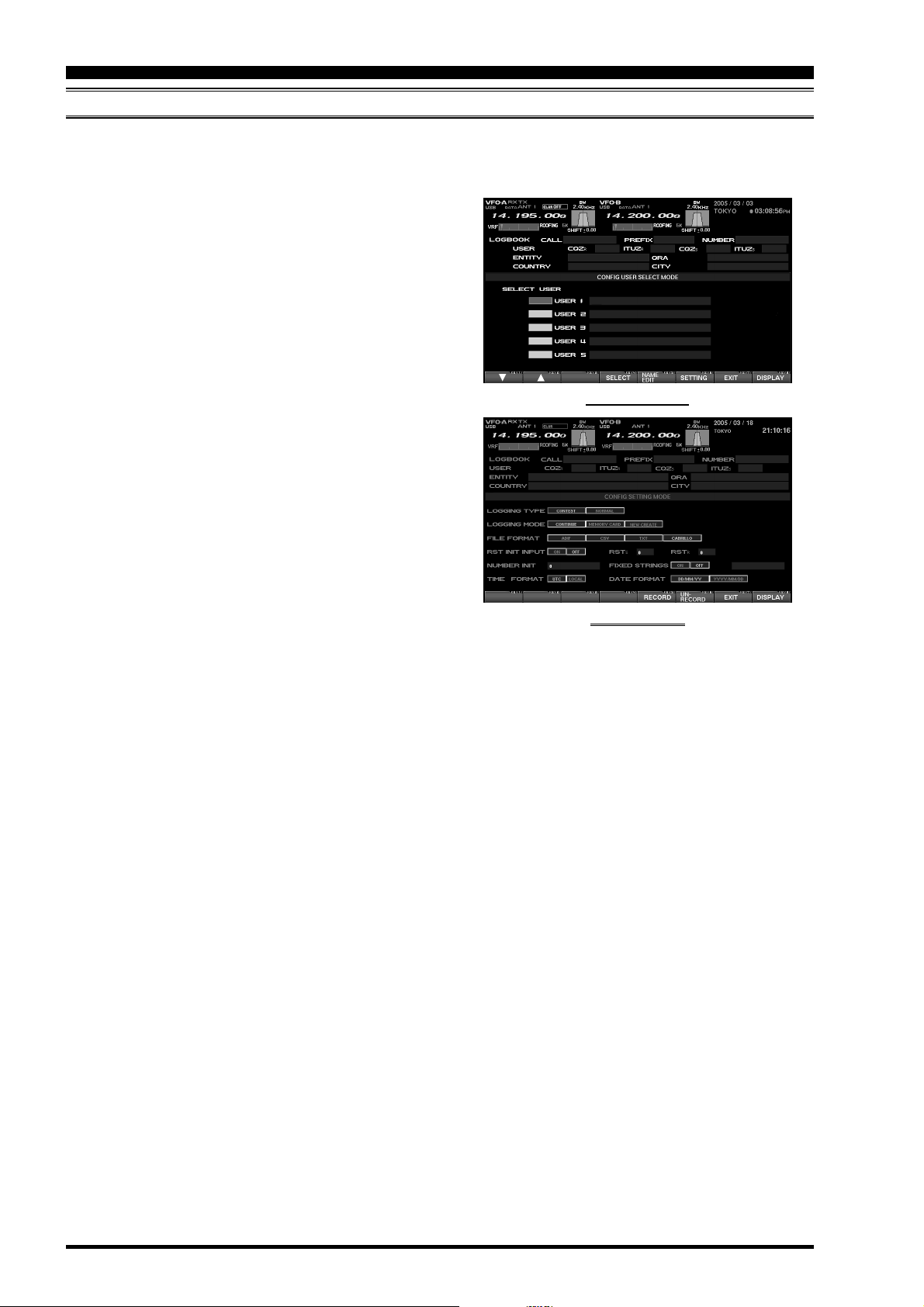
CONFIG SETTING
Up to five users may be registered into the Logbook. For use in a contest or otherwise, the settings for each
operator may be stored for later recall when that operator signs on. The operator’s identification may be entered
into the NAME column; both the name and callsign may be entered..
1. Referring to Figure 2 on page 23, press the
[F6](
CONFIG) key, then the [F1]() / [F2]() keys
to utilize the “SELECT USER” function.
2. When you want to register a new user, or change
the name of an existing user, press the [F5](NAME
EDIT) key and input the call sign and/or other in-
formation.
3. Press the [F5](NAME EDIT) key.
4. Press the [F6](CONFIG) key to engage the
“CONFIG SETTING” mode, then use the keyboard’s arrow keys to navigate to the needed
fields.
Please see the discussion below for details of the
“CONFIG SETTING” mode.
5. Press the [F5](RECORD) key to register.
If you want to un-do the registration, press
[F6](
UN-RECORD) key.
“USER SELCT” MODE
Advice: If no special entry is performed, the log will
register you as “USER1.”
“USER EDIT” MODE
Page 24
FTDX9000 TFT OPERATION MANUAL
Page 27

LOG BOOK FUNCTION
CONFIG SETTING
CONFING SETTING MODE SETUP
LOGGING TYPE (Setup of Log preferences)
CONTEST: This is a concise log format, with Callsign, RST, REM (Remarks) only being entered by the
operator; the Date, Time, Band, and Mode will automatically be entered and saved.
NORMAL: Besides the above information from the Contest log format, you can enter the Country, City,
Name, and other data.
In addition to the call sign, RST and REM, COUNTRY, CITY QRA, etc data can be added.
All of the DATE, TIME, CBAND, CMODE are automatically saved; once again, the Date,
Time, Band, and Mode will automatically be entered and saved.
LOGGING MODE (Logging Operational Mode)
NEW CREATE: Create a new Log Book.
CONTINUE: Add data to current log book.
MEMORY CARD: Download (read) log data from the CF card when turn on the rear panels main power
switch (see page 27 for details).
FILE FORMAT (Set up the file format for the log data)
ADIF: A worldwide standard format for DX contest log data.
CSV: Comma Separated Values format.
TXT: Text format.
CABRILLO: Worldwide standard format used for electronic submissions of Contest logs.
RST INIT INPUT (RST Automatic Input)
ON: Automatic filling in of the RSTR and RSTS (RST Received/Sent) reports is enabled. Manual
correction of individual log lines is, of course, possible.
OFF: On CW mode, “599” will be automatically entered, and on other modes “59” will be automatically
entered. You may correct these reports manually via the keyboard.
NUMBER INIT (Setting the Initial Sequential Number)
The initial Contest Number (or other sequential number to be assigned to each QSO) is entered here.
The automatic entry and transmission of the Contest Number will dramatically reduce fatigue over
many hours of operation.
FIXED STRINGS (Contest Number/Multiplier Memo On/Off Setup)
ON: In a CW contest, this is the area used for enabling input of multiple “memo” columns of data that
will be sent automatically, thus reducing fatigue.
OFF: If there is not need for multiple “memo” input columns, set this to Off.
TIME FORMAT (Conversion of UTC or Local Time for Logbook Time)
When log entry is done in LOCAL (LOCAL TIME-1), the log will automatically convert the time to UTC.
DATE FORMAT (Setup of Date Format to be day/month/year or year/month/day)
The Logbook can be set up for two different formats. When set to DD/MM/YY, March 28, 2005 will be
formatted as 28/03/05. If the format selected is YYYY/MM/DD, the same date will be formatted as 2005/
03/28.
FTDX9000 TFT OPERATION MANUAL Page 25
Page 28

LOG BOOK FUNCTION
LOG BOOK DATA INPUT
Log data may be entered by the user. Depending on the user setup (CONFIG) for “LOGGING TYPE,” there are
two logging modes: In the CONTEST mode, the operator just enters the callsign, signal report, and the REM
("remarks") fields, and the Date/Time/Band/Mode are all entered automatically. In the NORMAL mode, additional information may be entered, such as the Country, City, and Name. Up to 500 stations may store into a file.
Please enter the log data in accordance with the example in the illustration.
Advice: Before you start logging, we recommend that you perform the CONFIG SETTING MODE procedure
within the User setup (CONFIG) protocol.
1. Referring to the Figure 2 on page 23, use your
keyboard to enter the callsign in the CALL field.
Now press [ENTER].
2. The callsign will be checked against the previous
entries to see if it is a duplicate; if so, the
“CALLSIGN REPETITION CHECKLIST” will
open, listing this and any other duplicates. During
the QSO, if you wish to delete the callsign and
other information for this line, just press [ESC].
3. Enter all desired data in accordance with the example in the picture. When finished, push [EN-
TER] on the keyboard.
Note: In order to ensure preservation of log data, be
sure to Save the data frequently. It is always a good
idea to maintain a paper archive copy of log data.
Vertex Standard specifically disclaims responsibility
for any liability arising from the loss of log data.
Advice: When entering the Zone via the ITUZR field,
pressing the [ENTER] key will move you to the CQ
Zone (CQZR); from there, use the [] key to navigate back to the ITUZR field, if desired.
When doing input of the PREFIX, CQZR (or ITUZR),
ENTITY, and QRA data, please set the “LOGGING
TYPE” to “NORMAL” beforehand. This will allow you
to move from column to column by pressing the [EN-
TER] key. In addition, when (for example) entering
the PREFIX and pressing [ENTER], the PREFIX
SELECT LIST will appear, and the ENTITY, CQZR
(or ITUZR), and COUNTRY will automatically be entered.
“ENTRY” MODE
Page 26
FTDX9000 TFT OPERATION MANUAL
Page 29
LOG BOOK FUNCTION
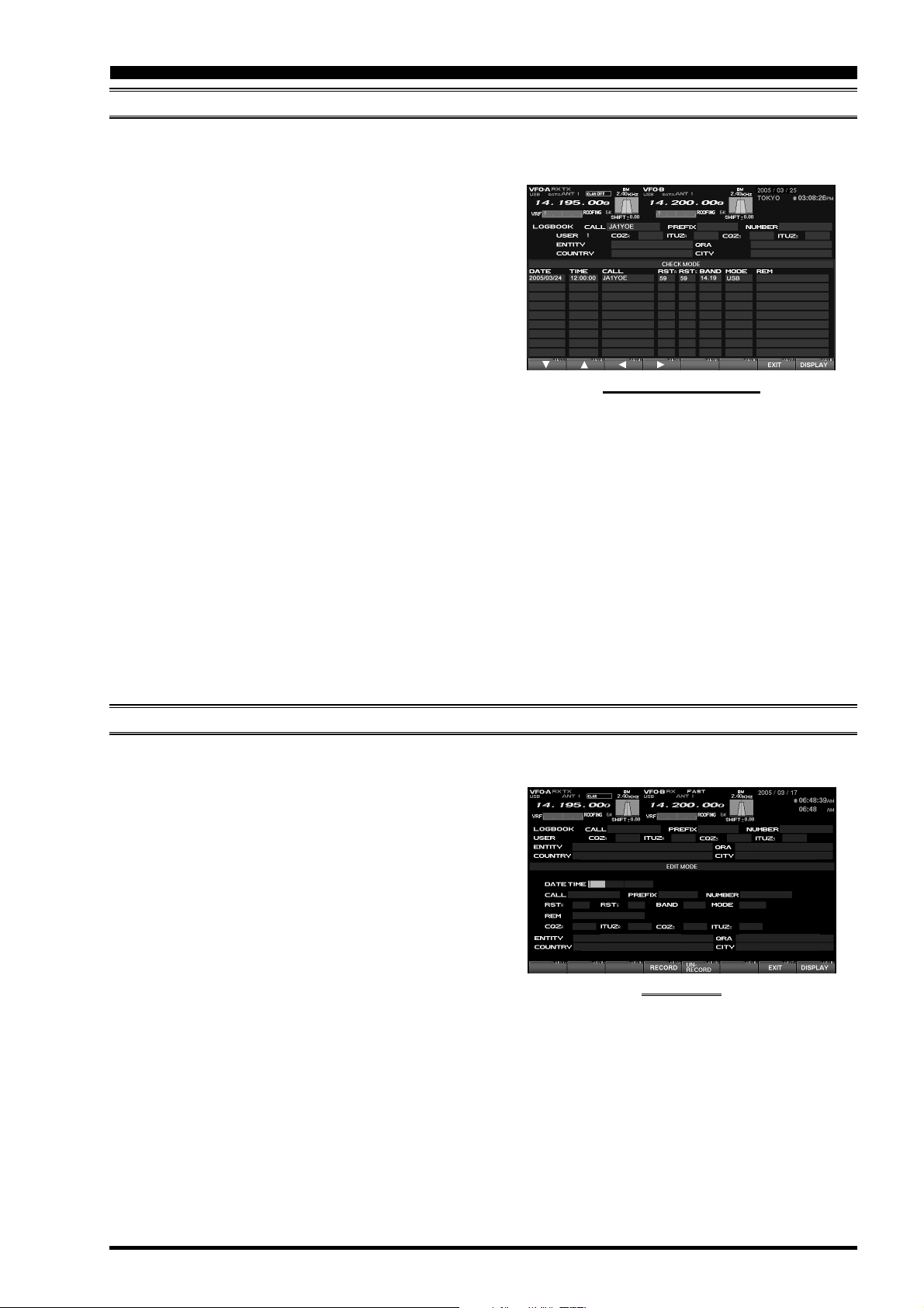
LOG BOOK PREVIOUS-QSO CHECK (CHECK
IIt is possible to check the log in search for previous QSOs with a particular station. When a log entry of interest
is found, you may edit the information on that line, if you like.
1. Referring to the Figure 2 on page 23, enter the
desired callsign into the CALL field.
2. Press the [F4](CHECK) key to show a list of any
previous QSOs with the specified station within
the current log. Any previous QSOs will appear
on a CHECK MODE list.
3. Use the [F1](), [F2](), [F3](), and [F4](
keys to scroll through the data on the CHECK
MODE list.
Quick Point: In the Step 2, before doing a check for a duplicate QSO, a copy is made of the QSO record, and
you may then do editing of that record. Use the [F1](), [F2](), [F3](), and [F4]() keys to select an item
from among CALL, RST, BAND, MODE and REM; when you press [F5](ONLY THIS), you’ll copy only that item.
When you press [F7](EXIT), the TFT image changes to what you see on page ??; press [ENTER] on the
keyboard to do a duplicate check, and press [ENTER] once more to return to the log input page and copy the
data.
If you select a line of data using the [F1]()
[F7](
ENTER) will cause the TFT image to change to what you see on page ??, and you may now press the
[
ENTER] key on the keyboard to do a duplicate check. Press [ENTER] once more to return to the log input page
and copy the data to that page (however, the NUMBER, RST, BAND, and MODE data will not be copied).
)
and [F2]()
“PREVIOUS-QSO CHECK” MODE
keys, pressing [F6](ALL SELECT) followed by
)
EDITING LOG BOOK ENTRIES
Previously-entered log data may be edited alter, if desired.
1. Referring to Figure 1 on page 23, press the
[F1]()/[F2]()
Editing.
2. Now you may ue the arrow keys on your keyboard
to move the highlighted area through the log.
3. Use the keyboard to change data within the currently-highlighted area.
4. Press the [F4](RECORD) key when you are fin-
ished editing the entries you have worked on.
If you do not wish to save your changes, press
the [F5](UN-RECORD) key instead.
Advice: Data may easily be deleted, if you make a
mistake, enter duplicate data accidentally, etc.
To erase data, use steps (1) and (2) to select the
data to be erased. Then press [ESC] on the keyboard;
the data will be deleted. Press [F4] (RECORD) to
return to the screen depicted on page ?? and end
this procedure.
key to select the log data to be
“EDITING” MODE
FTDX9000 TFT OPERATION MANUAL
Page 27
Page 30

LOG BOOK FUNCTION
SAVING LOG DATA
Log data can be saved in the supplied Compact Flash (CF) card.
1. Referring to Figure 1 on page 23, press the
[F7](
SAVE/LOAD) key to move to the Save/Load
page.
2. Press the [F5](SAVE) key to choose the “Save”
protocol.
3. Input the desired FILE NAME, and press the
[F6](GO)
Note: When the ERROR message “PLEASE CHECK
A DISK” is displayed at the right side of the MEM
CARD indication, please confirm that the CF card is
inserted correctly into its slot.
When memory data is saved in the CF card, any file
with the same name as the current file will be revised
(over-written), and the previous data will be deleted.
Please note.
key to save the data in the CF card.
Advice: The user configuration protocol (CONFIG)
allows you to specify the file format that is used for
saving log data. The available formats are:
ADIF (International Log Format) .................... adi
CSV (Cursor-Limited Values) ........................ csv
TXT (Tab-Limited Values) ............................... txt
CABRILLO ......................................... cabrillolog
(International Log Format)
“SAVE /LOAD” MODE
LOADING LOG DATA (LOAD
You may load log data from a CF card into your FTDX9000D (for example, an archive copy, or a log from a
different transceiver). Before starting, be sure the CF card containing the log data has been inserted into the CF
Card Slot.
1. Referring to Figure 1 on page 23, press the
[F7](
LOAD) key to engage the Save/Load mode.
2. Press the [F5](SAVE/LOAD) key to engage the
LOAD protocol.
3. Use the [F1]() and [F2]() keys to select the
file you wish to upload to the transceiver, then
press the [F6](GO) key to load the file.
Advice: When the ERROR message “PLEASE
CHECK A DISK” is displayed at the right side of the
MEM CARD indication, please confirm that the CF
card is inserted correctly into its slot.
When memory data is loaded from the CF card, the
current memories stored in the FTDX9000D will be
over-written, and the previous data is erased. We
recommend that you save and download the current
memory data to the CF card, if you want to use it
again later.
)
“SAVE /LOAD ” MODE
Page 28
FTDX9000 TFT OPERATION MANUAL
Page 31
LOG BOOK FUNCTION
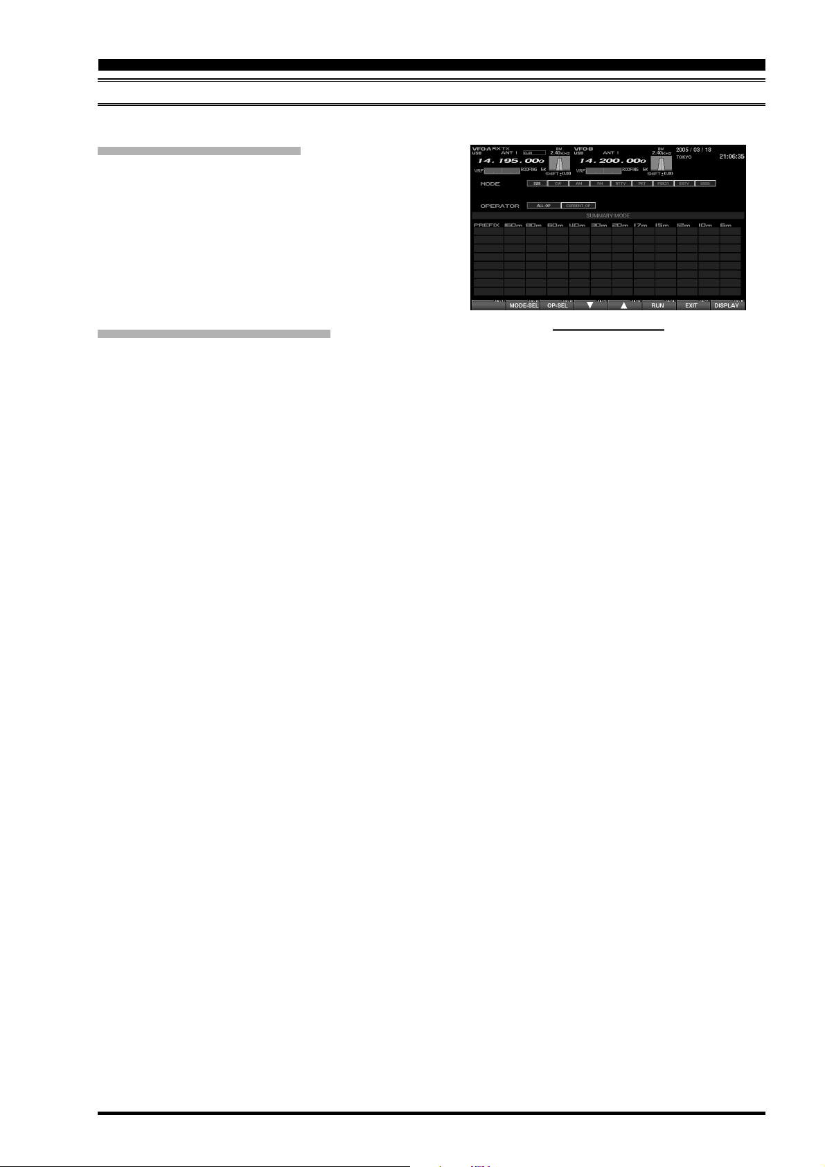
SUMMARY CHECK
You may do a band-by band, mode-by mode, or “all log” summary of your log data.
MODE-BASED SUMMARY CHECK
1. Referring to Figure 2 on page 23, pressing
[F5](
SUMMARY) to brings up the Summary page,
and you may then press [F2](MODE-SEL) and
select the desired mode, using the keyboard’s arrow keys.
2. When you press [F5](RUN), the summary list for
the selected mode will be displayed.
3. Use the [F1]() and [F2]() keys to scroll through
the summary list.
OPERATOR-BASED SUMMARY CHECK
1. Referring to Figure 2 on page 23, press
[F5](
SUMMARY) to bring up the Summary page,
then press [F3](OP-SEL) and then use the
keyboard's arrow keys to select “ALL-OP” or
“CURRENT OP” as desired.
ALL-OP: All log data from all operators reg-
istered on the data stored on the
CF card will be displayed.
CURRENT OP: Only the log data from the cur-
rent operator will be displayed.
2. Press [F5](RUN) to display the summary list for
the selected operator, or all operators..
3. Use the [F1]() and [F2]() keys to scroll through
the summary list.
“SUMMARY CHECK” MODE
Note: The Summary Check function requires that
“NORMAL” be selected as the “Log Type” before you
start, and only logs containing the PREFIX may be
used for this function.
FTDX9000 TFT OPERATION MANUAL
Page 29
Page 32

TEMPERATURE / SWR INDICATION
ABOUT THE TEMPERATURE/SWR INDICATION
It is possible to display the VDD (TX Final Amplifier) voltage, bias voltage, the temperature of the heat sink of the
final devices, and the (swept) SWR characteristics/performance of the antenna connected, all together on the
TFT screen.
E
XPLANATION OF THE FUNCTION KEYS ON THE TEMPERATURE
/SWR I
NDICATION SCREEN
[F2](MARKER
This key turns the marker on the SWR characteristic graph on and off.
The marker lets you identify quickly the frequency
on which a particular SWR reading is being observed.
[F3]()
This key moves the marker cursor to the left.
[F4](
This key moves the marker cursor to the right.
)
)
[F5](
ERASE
Press this key when you want to clear the measured SWR at the marker’s current point.
[F6](
SWR CK
To check the SWR on a particular frequency, rotate the Main dial, and set the frequency to be
measured Now press [F6](SWR CK); the SWR
will be measured and the result will be displayed
on the screen.
[
DISP](DISPLAY
Pressing this key momentarily takes you to the
“GREAT CIRCLE MAP/ROTATOR CONTROL FUNCTION”
screen.
If you press and hold in this key for 2 seconds,
the screen will move to the “LOG BOOK” screen.
)
)
)
Page 30
FTDX9000 TFT OPERATION MANUAL
Page 33

TEMPERATURE / SWR INDICATION
GRAPHIC METER DISPLAYS
VDD
The drain voltage of the final FET is measured
and displayed here. The measurement range is
0-60 V, and the proper voltage is around 50 V. On
TX, if around 50 V is displayed, the transceiver is
operating normally.
BIAS
While operating with the Class-A, and the bias is
changed by rotating the BIAS knob from class A to
class AB, this indication can be used to observe the
current setting. The indication is 0-100 % and “0%”
means class AB, while “100%” means class A.
Even if the Bias is varied, the RF output will not
change (up to the 75 Watts of maximum power
under class A), and you can change the bias safely
even when you are using a linear amplifier.
TEMP
This indicates the temperature (measured) of the
final amplifier FETs’ heat sink.
The measured temperature range of this meter is
0 - 100 °C, and above 80 °C is the “Red Zone”
temperature range to be avoided, so as to ensure
a safe operating temperature range. When the
temperature rises above 80 °C, the fan speed will
increase by a factor of four, providing a significant
increase in air flow. The heat sink temperature
may rise appreciably during Class-A operation,
especially if the ambient temperature is warm, and
we recommend that you monitor the temperature
during Class-A transmission, adjusting the Bias
control downward (more toward Class AB) if excessive heating is observed. A lower bias level
will cause less heat to be dissipated, thus reducing the heat sink temperature.
SWR
This displays the SWR characteristic of the amateur band that you are currently using, with points
along the graph indicating the frequencies that
have been measured.
SWEPT SWR DISPLAY
It is possible to show the SWR characteristics and antenna performance on a graph by measuring the SWR at
various points across an amateur band.
In order to measure the SWR of the antenna system
correctly, please turn off the antenna tuner before
measuring the SWR.
1. Please confirm that the RF output is over 10 Watts.
In order to measure the SWR correctly, 10 Watts
of RF output will be required. The TX RF output
may be adjusted using the RF PWR knob.
2. Please confirm that the test transmission will not
cause QRM to other stations (be sure to ask if the
frequency is clear, and identify in accordance with
regulations). Then press the [F6](SWR CK) key.
3. Perform the above procedure several times across
the band, and the SWR measured at the various
test frequencies will automatically be plotted on
the chart, creating a performance characteristic
graph for the current frequency range.
Advice: For the purposes of plotting the SWR across
the band, the resolution of the graph is every 10 kHz
on the 1.8 ~ 24 .9 MHz bands, and 100 kHz on the
28/50 MHz bands.
If a measurement is done on the same frequency as
where a previous measurement was made, the old
data will cleared and the new measurement data will
replace it.
Always observe proper operating courtesy to others, and check to be sure the frequency is clear
before performing any SWR measurements.
FTDX9000 TFT OPERATION MANUAL
Page 31
Page 34

TEMPERATURE / SWR INDICATION
USING THE MARKER ON THE SWR GRAPH
It is possible to read the measured SWR value by placing the marker onto the desired frequency (measurement
test point) of the SWR graph.
1. Press the [F2](MARKER) key to turn the marker
function on; the marker cursor will be displayed.
2. Use the [F3]() and [F4]() keys to move the
marker line and select the desired frequency for
which you want to read the previously-measured
SWR.
Advice: Please use an antenna with the SWR below
1.5:1. If the SWR is over 1.5:1, the final protection
circuit activates, and the RF output power may be
reduced.
If the SWR is over 3.0 in the amateur band, there is a
possibility that the coaxial cable or the antenna itself
(antenna system) may have some problem. Please
take the necessary corrective action so as to ensure
optimum, safe performance in your station.
The antenna tuner in the radio can match the SWR
between the transceiver and the antenna; however,
keep in mind that this is not affecting the SWR at the
antenna feedpoint itself. In cases of higher-than-desirable SWR, we recommend corrective action be
taken at the antenna itself.
When you want to clear the measured SWR value at
the marker test point, press the [F2](MARKER) key.
Page 32
FTDX9000 TFT OPERATION MANUAL
Page 35

NOTE
FTDX9000 TFT OPERATION MANUAL
Page 33
Page 36

G
REAT
C
IRCLE
M
AP
/ R
OTATOR
C
ONTROL FUNCTION
ABOUT THE GREAT CIRCLE MAP/ROTATOR CONTROL FUNCTION SCREEN
In order to direct the antenna to the desired/opposite station, a Great Circle Map can be displayed on the screen.
This Great Circle map will show your location at the center of the map, and you can easily recognize and confirm
the direction your antenna should be pointed to work a station elsewhere in the world.
In addition, when a Yaesu Rotator (G-800DXA, G-1000DXA, or G-2800DXA) is connected to this transceiver,
the transceiver can control the direction of the rotation, rotation speed, etc. on the TFT screen. In this case, the
rotator has to be connected to the FTDX9000 using a special cable. For details, please contact WDXC.
E
XPLANATION OF THE FUNCTION KEYS ON THE GREAT CIRCLE MAP/ROTATOR CONTROL SCREEN
[F1](ZONE
This key moves you to a screen used for input of
the location of the other station. When the country name and the city name are entered, your location and the opposite station’s will be connected
with a line and displayed on the Great Circle map
(short path only). The location of the other station
can be set when Rotator control is in the manual
mode.
Press the [F4](MODE) key as needed to select
the manual mode. The mode is indicated in the
middle of the TFT display.
)
[F2](
When a Yaesu Rotator (G-800DXA, G-1000DXA,
or G-2800DXA) is connected to the transceiver,
and you press this key, you can rotate the antenna
in the CCW (counter clockwise) direction.
[F3](CW
When a Yaesu Rotator (G-800DXA, G-1000DXA,
or G-2800DXA) is connected to the transceiver,
and you press this key, you can rotate the antenna
in the CW (clockwise) direction.
CCW
)
)
Page 34
FTDX9000 TFT OPERATION MANUAL
Page 37

G
REAT
E
XPLANATION OF THE FUNCTION KEYS ON THE GREAT CIRCLE MAP/ROTATOR CONTROL SCREEN
C
IRCLE
M
AP
/ R
OTATOR
C
ONTROL FUNCTION
[F4](
MODE
By pressing this key, the rotation control mode can
be selected. With every momentary press, the
mode changes as shown below. The mode is indicated in the middle of the TFT display.
MANUAL
MANUAL
PRESET
MEMORY
[F5](
SLOW
When you want to slow down the speed of the
rotation, this key is used. Normally, you will use
the "100 %" value; once 100 % is selected, you
typically will not need to use this key.
)
PRESET
: CW/CCW control is performed
manually.
: Rotation to the “PRESET” direction
is selected.
: Rotation to one of the stored rota-
tion memories is selected.
)
MEMORY MANUAL ......
MODE Indicator
[F6](
FAST
When you want to increase the speed of the rotation, this key is used. Normally, you will use the
“100 %” value; once 100 % is selected, you typically will not need to use this key.
[F7](
MAP
This key switches the TFT between the Great
Circle Map and the regular Rotator Control compass display.
Advice: If the Great Circle display is utilized, you
probably already know the approximate location
of the other station on the map; so even if the
country name and the city name are not entered
into the radio, the Great Circle map provides a
convenient tool for rotating the antenna to the
optimum heading.
If your own location is not indicated at the center
of the Great Circle Map, please set the local time
(which registers the location where the radio is
operated). If this is not done, the various functions of the World clock and Great Circle map will
not function correctly. Regarding the setting of the
Local time, please see the “PLEASE READ THIS
FIRST” document.
[
DISP](DISPLAY
Press this key to move to the “MEMORY CHANNEL
LIST” screen.
Press and hold in this key for two seconds to revert to the “TEMPERATURE/SWR INDICA TION” screen.
)
)
)
“GREAT CIRCLE MAP” DISPLAY
FTDX9000 TFT OPERATION MANUAL
Page 35
Page 38

G
REAT
C
IRCLE
M
AP
/ R
OTATOR
C
ONTROL FUNCTION
MANUAL MODE
It is possible to operate/control the rotator manually. If the other station’s location has been entered, the location
of the other station and yours will be connected with a line on the Great Circle Map, and you can rotate the
antenna manually to the direction of the other station.
MANUAL OPERATION
Use the [F2](CCW) key to rotate the antenna counterclockwise, or the [F3](CW) key to cause clockwise
rotation of your antenna.
“REGULAR COMPASS” DISPLAY
MANUAL OPERATION
1. Press the [F4](MODE) key, as necessary, to se-
lect the “PRESET” or “MANUAL” mode. The mode
is indicated in the middle of the TFT display.
2. Press the [F7](MAP) key to display the Great
Circle Map on the screen. If you know the approximate location of the country of the other station,
rotate your antenna by looking the map and rotating the antenna in the appropriate direction.
3. If you want to display a station on the Great Circle
Map, start by pressing the [F1](ZONE) key; the
World Map’s zones will be displayed.
Select the Zone of the other station by pressing
the [F1](), [F2](), [F3](), and [F4]() keys,
then press the [F7](SELECT) key momentarily.
The list of the countries in the selected Zone will
be shown.
Select the country name of the other station by
pressing the [F1](), [F2](), [F3](), and [F4](
keys, then press the [F7](SELECT) key momentarily.
Now, the list of the city names within the selected
country will appear, and you will need to select
one of the city names by pressing [F1](), [F2](),
[F3]()
[F7](
Note; in some countries, there may be only one
city in the country; select that one city anyway.
4. Automatically the screen will revert to the Great
Circle Map, and the location of the other station
will plotted on the map, connected by a line to
your location via the short path.
5. Use the [F2](CCW) and [F3](CW) keys to rotate
your antenna system to the direction just plotted
on the TFT.
, and [F4]() keys. Now press the
SELECT) key .
)
Page 36
“GREAT CIRCLE MAP” DISPLAY
FTDX9000 TFT OPERATION MANUAL
Page 39

G
REAT
C
IRCLE
M
AP
/ R
OTATOR
C
ONTROL FUNCTION
PRESET MODE
The Preset mode lets you set the desired direction of the rotator in advance, so you can automatically rotate your
Yaesu rotator to the designated direction. Use of a Yaesu Rotator (G-800DXA, G-1000DXA, or G-2800DXA)
requires the connection of the rotator cable to the connector located on the back of the transceiver.
1. Press the [F4](MODE) key, as necessary, to se-
lect the “PRESET” mode.
2. Press the [F7](MAP) key, if necessary, to bring up
the Great Circle map screen.
3. Press the [F2](CCW) or [F3](CW) key to set the
Preset pointer to the direction of the other station's
location.
4. Press the [F5](START) key to engage hands-free
rotation to the beam heading you just set up in the
previous step.
You may stop the manually by pressing the
[F5](
ST ART) key again.
“REGULAR COMPASS” DISPLA Y
“GREAT CIRCLE MAP” DISPLAY
FTDX9000 TFT OPERATION MANUAL
Page 37
Page 40

G
REAT
C
IRCLE
M
AP
/ R
OTATOR
C
ONTROL FUNCTION
MEMORY MODE
It is possible to rotate the antenna automatically to a direction or directions which you store into memory in
advance. Use of a Yaesu Rotator (G-800DXA, G-1000DXA , or G-2800DXA) requires the connection of the
rotator cable to the connector located on the back of the transceiver.
PROGRAMMING BEAM HEADINGS INTO MEMORY
1. Press the [F4](MODE) key, as necessary, to se-
lect the “PRESET” or “MANUAL” mode.
2. Use the techniques learned previously to rotate
the antenna to the desired beam heading.
3. Now press the [F4](MODE) key to select the
MEMORY mode.
4. Select the desired memory channel register by
using the the [F2]() key and [F3]() keys, then
press the [F6](MW) key to memorize the programmed beam heading.
Advice: The maximum number of beam-heading
memories which can be stored is 9.
If you have connected your after-market keyboard to
the transceiver, you can append a name (tag) to the
memory channel (maximum: 6 characters). It often
is convenient to enter the callsign of a station, or perhaps a label such as “Europe” for easy reference.
The method of entering the name tag into a memory
is described below.
“REGULAR COMPASS” DISPLAY
1. Use the [F2]() key and [F3]() keys to select
the rotator memory register onto which you wish
to append a name tag.
2. Press [ENTER] on your keyboard; the cursor on
the screen will blink.
3. Use your keyboard to enter the name tag; a maximum of six characters may be utilized.
MEMORY RECALL
1. Use the [F2]() key and [F3]() keys to select
the desired location from the rotator memory list.
2. When you momentarily press the [F5](MR/
ERASE) key, the rotator will turn to the direction
(beam heading) that has been memorized.
ERASING MEMORY
1. Use the [F2]() key and [F3]() keys to select
the rotator memory you wish to erase.
2. Press the [F5](MR/ERASE) key for 2 seconds to
erase the memory’s data.
Note: Once erased, memory data cannot be restored!
“GREAT CIRCLE MAP” DISPLAY
Page 38
FTDX9000 TFT OPERATION MANUAL
Page 41

USING THE MEMORY CHANNEL LIST
ABOUT THE MEMORY CHANNEL LIST
This is the screen which displays the transceiver's memory channels. On the list, the channel number, ID tag,
frequency, and operating mode are shown. The FTDX9000 has an extensive memory system of 99 channels
that may be arrayed into up to six groups, and you can check the entire memory system's status by viewing this
screen.
EXPLANATION OF THE FUNCTION KEYS ON THE MEMORY CHANNEL LIST SCREEN
[F2](LOAD
Press this key to load memory data previously
saved on the CF card to the transceiver.
[F3](
SAVE
Press this key to save the current memory data to
the CF card.
[F5](MASK/RESTROKE
It is possible to erase the currently-selected
memory channel’s data by pressing this key. If
you want to restore the erased memory data, press
this key again after erasing the memory.
)
)
)
[F6]()
Use this key to move the highlighted field on the
memory list downward.
[F7]()
Use this key to move the highlighted field on the
memory list upward.
[
DISP](DISPLAY
Press this key momentarily to move to the World
Clock page.
Press and hold this key in for two seconds to revert to the Rotator Control page.
)
FTDX9000 TFT OPERATION MANUAL
Page 39
Page 42
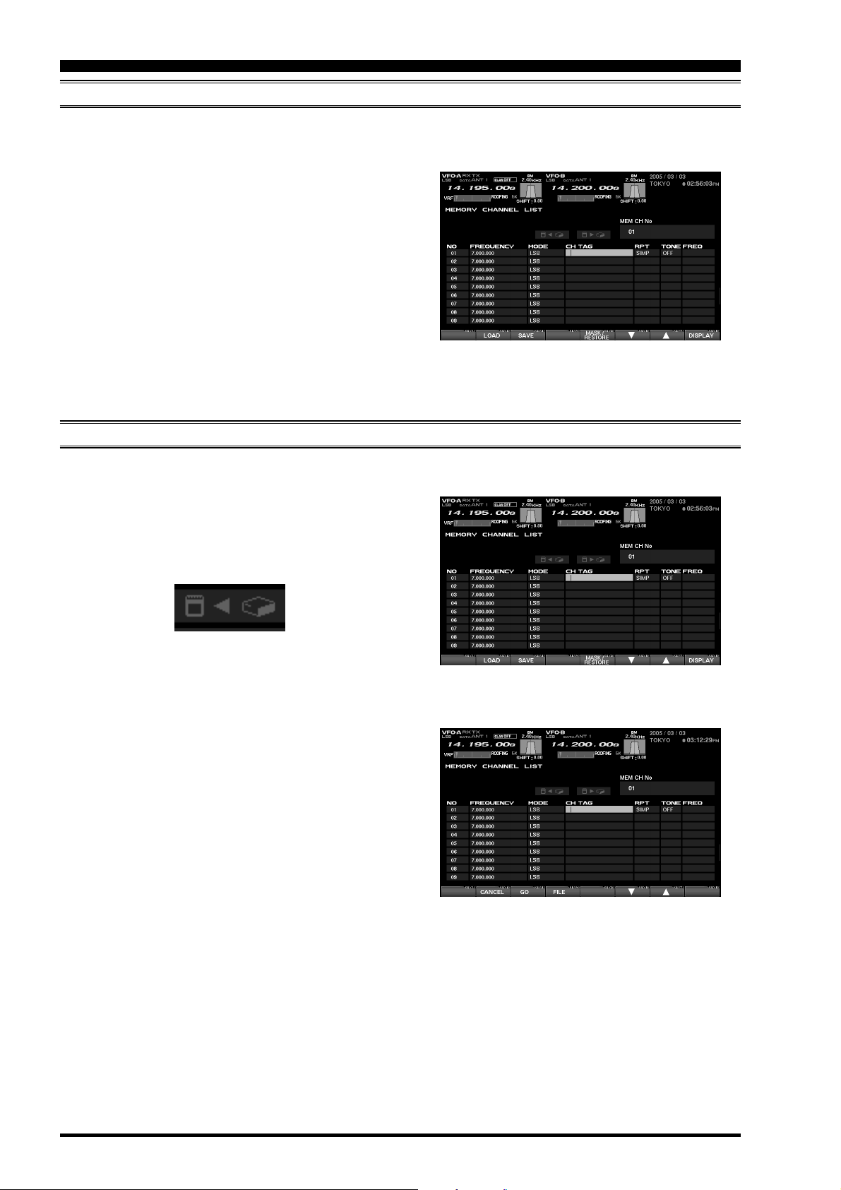
USING THE MEMORY CHANNEL LIST
ERASING A MEMORY CHANNEL/RESTORING AN ERASED MEMORY CHANNEL
You can erase data from any memory channel which is no longer needed. It also is possible to restore (immediately after deletion) erased memory channel data, in case you erase something by accident.
1. Select the memory channel you want to erase by
pressing the [F6]() key or [F7]() key.
2. To mask the current memory's contents, press the
[F5](
MASK/RESTORE) key. If you want to restore
the erased memory channel’s data, press the
[F5](
MASK/RESTORE) key once more.
Advice: Memory channel which has been erased can
be restored by pressing the [F5](MASK/RESTORE
key again, but if any other key has been pressed after you erased the memory channel, the memory cannot be restored.
SAVING MEMORY DATA
)
Press [F5](MASK/RESTORE
)
Memory data from the FTDX9000D’s internal memory may be saved to the supplied Compact Flash (CF) card.
1. Press the [F3](SAVE) key to open the Save win-
dow.
If there are several file names stored, select the
desired file by pressing the [F6]() key and
[F7]()
2. If you want to over-write the file name, go to step 3.
If you do not want to over-write the data on an
existing file name, and want to save the data in
the new file. Press the [F4](FILE) key; now enter
the desired file name from your keyboard (the file
extension will be “.mcl” for Menu data).
3. Press the [F3](GO) key to save the data into the
CF card.
If you want to cancel the saving of the memory
data, press the [F2](CANCEL) key.
Advice: When the ERROR message “PLEASE
CHECK A DISK” appears on the right side of the MEM
CARD notation, please confirm that the CF card is
inserted correctly into its slot.
When memory data is saved in the CF card under a
previously-used file name, the old/previous data will
be revised and the old data erased.
keys.
Press [F3](SAVE
Press [F3](GO
)
)
Page 40
FTDX9000 TFT OPERATION MANUAL
Page 43
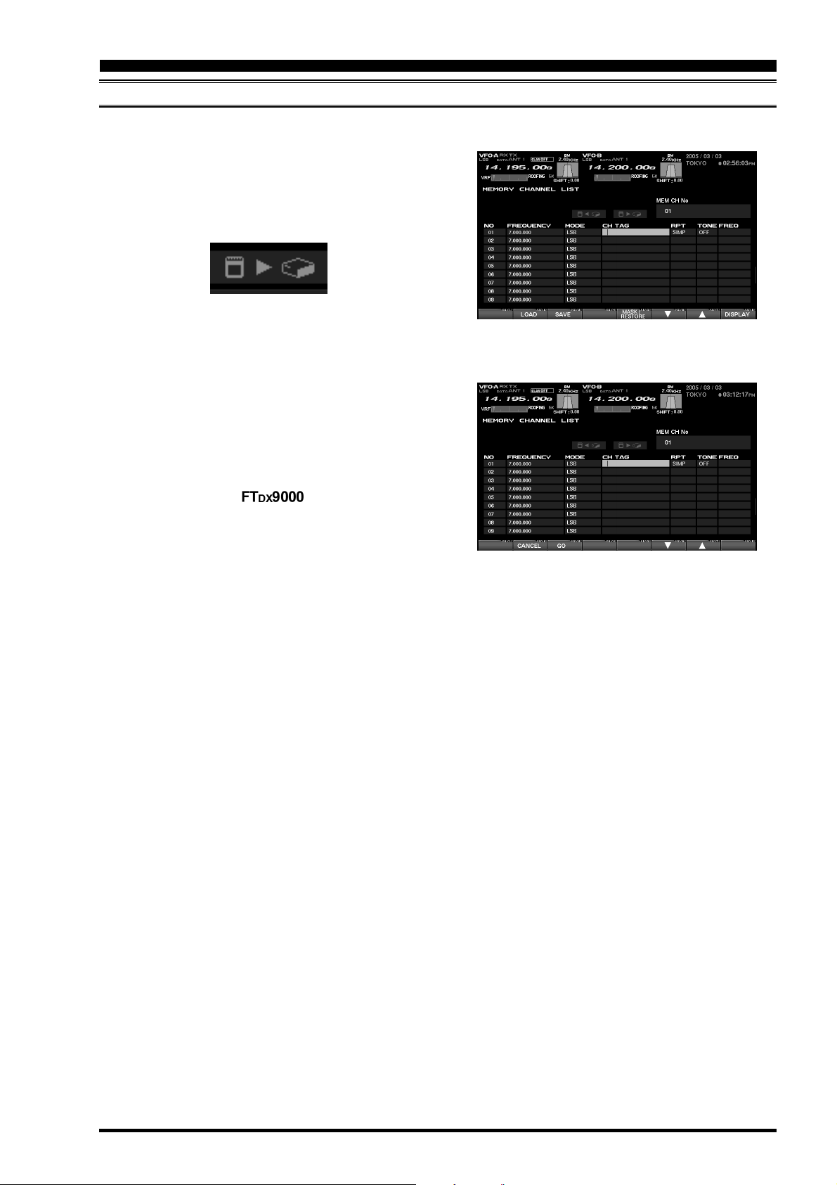
USING THE MEMORY CHANNEL LIST
LOADING MEMORY DATA
Loading Memory Data from the CF Card to the Memory on the FTDX9000.
1. Press the [F2](LOAD) key to open the memory
loading window.
If there are multiple file names stored on the CF
card, select the desired file by pressing the [F6](
key or [F7]() key.
)
2. Press the [F3](GO) key to commence loading of
the memory data to the transceiver. If you wish to
cancel the download, press the [F2](CANCEL
key.
Advice: When the ERROR message “PLEASE
CHECK A DISK” appears on the right side of the MEM
CARD notation, please confirm that the CF card is
inserted correctly into its slot.
When the memory data is loaded from the CF card
to the memory on the , all previous data
will be over-written and the old data will be erased.
Please remember to save the current memory contents to the CF card, if you want to retrieve it later.
)
Press [F2](LOAD
)
Press [F3](GO
)
FTDX9000 TFT OPERATION MANUAL
Page 41
Page 44

USING THE MENU MODE
ABOUT THE MENU MODE
The FTDX9000’s Menu mode includes 161 different settings, used for configuration of various transceiver features and functions that generally are set once, and then seldom changed.
Advice: The 161 items in the menu are grouped into 11 categories, and the groups are displayed at the left top
of the menu list screen. It will be most convenient for you if you initially select the group, by rotating the Main Dial,
and then select the individual menu item you want to work on.
GROUP NAMES IN THE MENU
AGC
This group is used for the setting up the AGC timing parameters. The AGC characteristics can significantly affect the performance of the receiver,
and we recommend that you not change the settings in normal use. If the setting gets changed
by accident, please do the menu mode reset described at the right.
DISPLAY
This is the display-related group, related to the
Dimmer, TFT color, clarifier display, etc.
1. First turn off the radio by pressing the front
panel [POWER] switch.
2. Now, turn on the radio while pressing the
[
MNU] key. The menu mode will be reset,
and the factory default configurations will
come back.
MENU MODE RESET
FH-2
This is the group relating to the FH-2 keypad setup.
GENERAL
This group covers miscellaneous items which are
not included in other groups.
MODE-AM, MODE-CW, MODE-DATA, MODE-DM,
MODE-PKT, MODE-RTTY, MODE-SSB
These are the groups related to items associated
with different operating modes, and which may
be configured separately.
RX AUDIO
This is the group related to the setting of the headphones and internal speakers.
RX DSP
This group pertains to the settings for the RX filter
bandwidth, as well as other receiver filter configurations.
SCOPE
This group is used to set the starting frequency
for the Spectrum scope on the FIX mode (band
by band).
TUNING
This is the Dial step configuration group.
TX AUDIO
This group is used for setup of the parametric
equalizer.
TX GENERAL
This group is used for setting the TX RF output,
configuration of linear amplifier switching, full-duplex operation, etc.
Page 42
FTDX9000 TFT OPERATION MANUAL
Page 45

USING THE MENU MODE
EXPLANATION OF THE FUNCTION KEYS ON THE MENU MODE SCREEN
[F2](LOAD
Press this key to download previously-used Menu
settings from the CF card to the transceiver.
[F3](
SAVE
Press this key to save the current Menu settings
to the CF card.
[F4](
Use this key to select the configuration value of
the menu item. The value may also be changed
by rotating the CLAR/VFO-B knob.
[F5]()
Use this key to select the configuration value of
the menu item. The value may also be changed
by rotating the CLAR/VFO-B knob.
)
)
)
[F6]()
This is the “down” key for scrolling through the
menu mode list. The items also can be selected
by rotating the Main Tunig knob.
[F7]()
This is the “up” key for scrolling through the menu
mode list. The items also can be selected by rotating the Main Tunig knob.
When you have completed making all changes to the
menu setting(s), press the [MNU] key for 2 seconds to lock in the changes. If you do not want to
keep the changes, press the [MNU] key only momentarily; the radio will come back to the previous menu
status that was present before you made the changes.
FTDX9000 TFT OPERATION MANUAL
Page 43
Page 46
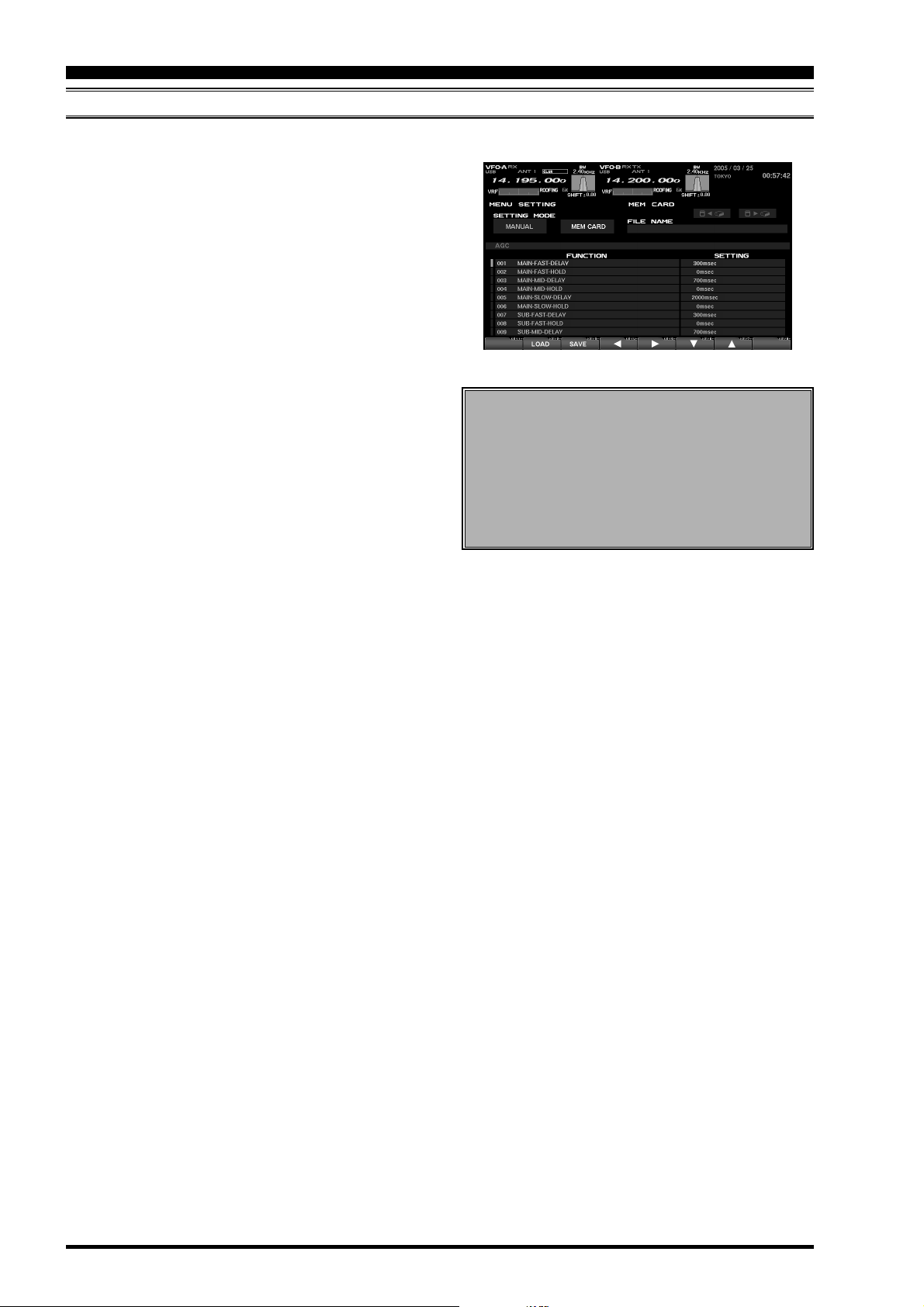
USING THE MENU MODE
MENU MODE CONFIGURATION CHANGES
When you want to change something in a menu mode setting, follow the procedure described below.
1. Press the [MNU] key momentarily.
The TFT will display the Menu page. Included on
this page will be the Menu Group, Menu Item
Name, Menu Item Number, and the current status (setting) for each Menu item.
2. Use the Main Tuning Dial, or the the [F6]()/
[F7]()
work on.
3. Use the CLAR/VFO-B knob, or the [F4]()/[5](
keys, to change the setting of the selected Menu
item.
4. Press the [MNU] key is pressed for 2 seconds to
save (within the transceiver) the new setting; the
menu screen will close, and you will then return to
the screen that was in use before entering the
menu mode.
If you press the [MNU] key momentarily to exit,
the new settings will not be saved, and you will
exit from the menu mode without retaining the new
configuration.
keys, to select the Menu item you wish to
)
MENU MODE RESET
1. First turn off the radio by pressing the front
panel [POWER] switch.
2. Now, turn on the radio while pressing the
[
MNU] key. The menu mode will be reset, and
the factory default configurations will come
back.
Page 44
FTDX9000 TFT OPERATION MANUAL
Page 47

USING THE MENU MODE
SAVING MENU CONFIGURATION DATA
You may save the current Menu configuration data to the CF card, for archive purposes or for quick changes in
extensive transceiver settings for different operating applications.
1. Press the [F3](SAVE) key to open the Save win-
dow. If there are multiple file names already stored,
select the desired file by pressing the [F6]() and
[F7]()
2. If you want to over-write the file name, go to step 3.
If you do not want to over-write the data on an
existing file name, and want to save the data in
the new file. Press the [F4](FILE) key; now enter
the desired file name from your keyboard (the file
extension will be “.mep” for Menu data).
3. Press the [F3](GO) key to save the data into the
CF card.
If you wish to cancel the saving of the data, press
the [F2](CANCEL) key.
keys.
Press [F3](SAVE
)
Advice: When the ERROR message “PLEASE
CHECK A DISK” is displayed at the right side of the
MEM CARD notation, please confirm that the CF card
is inserted correctly into its slot.
When the memory data is saved in the CF card under a previously-used file name, the old/previous data
will be over-written and the old data erased.
Press [F3](GO
)
FTDX9000 TFT OPERATION MANUAL
Page 45
Page 48

USING THE MENU MODE
LOADING MENU DATA
Loading Menu Data from the CF Card
1. Press the [F2](LOAD) key to open the “Load” win-
dow. If there are several file names stored, select
the desired file by pressing the [F6]() and [F7](
keys.
2. Press the [F3](GO) key to download the Menu con-
figuration from the CF card to the radio.
To cancel the download, press the [F2](CANCEL
key.
Advice: When the ERROR message “PLEASE
CHECK A DISK” is displayed at the right side of the
MEM CARD notation, please confirm that the CF card
is inserted correctly into its slot.
When the Menu data is loaded from the CF card to
the Menu on the FTDX9000, the old/previous data will
be over-written, and the old data erased.
)
)
Press [F2](LOAD
)
Press [F3](GO
)
Page 46
FTDX9000 TFT OPERATION MANUAL
Page 49

NOTE
FTDX9000 TFT OPERATION MANUAL
Page 47
Page 50

NOTE
Page 48
FTDX9000 TFT OPERATION MANUAL
Page 51

FTDX9000 TFT OPERATION MANUAL
Page 52

Copyright 2005
VERTEX STANDARD CO., LTD.
All rights reserved
No portion of this manual
may be reproduced without
the permission of
VERTEX STANDARD CO., LTD.
Printed in Japan.
EH010H110
0506i-AY
FTDX9000 TFT OPERATION MANUAL
 Loading...