

Page 1
FT
Operation Manual
DX
9000D
Page 2

Page 3
GENERAL DESCRIPTION
We wish to take this opportunity to thank you for your purchase of the FT DX 9000D Transceiver!
The FT
engineering, design, and manufacturing know how. As pioneers in the development of SSB, we have led the technological
advances in Amateur Radio communications over the last half century. And now, with the introduction of the FT DX 9000D,
we again lead the way with a no-compromise 21st-century design that will make your operating dreams come true. More
importantly, it is a radio that will let your skills and experience find expression, as you harness the excitement of HF
operating like you’ve never done before!
DX 9000D is the culmination of a four-year design project. But it also is the product of our company’s fifty years of
ABOUT THIS MANUAL. . .
The FT DX 9000D is a leading-edge transceiver with a number of new and exciting features, some of which may be
unfamiliar to you. In order to gain the most enjoyment and operating efficiency from your FT DX 9000D, we recommend
that you read this manual in its entirety, and keep it handy for reference as you explore the many capabilities of your new
transceiver.
Before using your FT DX 9000D, be sure to read and follow the instructions in the “Before You Begin” section of this
manual.
CONVENTIONS USED IN THIS MANUAL
Please note the conventions, described below, for operational commands and texts included in this manual.
(# ) ..... This refers to a switch or knob used for controlling a particular function. The name or number inside the
brackets designate the name of the switch/knob, or its reference number within this manual
.............. This is the name of a switch or knob.
[ ] .............. This indicates one of the [F1] ~ [F8] “Soft Keys” below the TFT display.
XX ........... In the texts, you may be advised to press a button momentarily, or press and hold it in for a time interval (such
as two seconds). Please be sure to observe the proper procedure when pressing a button.
OO ........... This indicates the pressing of a button when a “momentary” press is the only selection available.
Note ......................................... This is used for a note as to a particular point of interest.
Advice ..................................... This is used to amplify or expand on instructions, so as to recommend a way to gain
maximum benefit from a feature or function.
Example .................................. This is used to demonstrate an example of how a feature or function should work or be
programmed.
Quick Note / Quick Point This is used for a brief explanation of a particular aspect of operation.
Terminology ........................... An explanation of a term or expression used in this manual.
ABOUT THE TFT DISPLAY
In the FT DX 9000 Series, a large 6.5” (800 x 480 dot) TFT is built into the FT DX 9000D version, and is optional on other
versions. Please see the separate TFT Operation Manual for details regarding TFT operation.
H The TFT is a precision-designed, advanced display unit. You may observe, inside the TFT panel, a black point, or a
luminescent point or points; these are normal, and do not indicate a defective TFT. Please note.
H If you turn on the FT DX 9000 (with the TFT) in a cold environment, or if the transceiver itself is very cold, it may require
several minutes for the TFT to warm up to full brilliance of color and full illumination. This is a normal condition, and
does not indicate a breakdown.
H There may be times when the TFT display illumination appears not to be uniform, but this is a normal condition.
This device is designed for Amateur Radio operation only. Operation on the Amateur Radio bands requires a license, in
accordance with the telecommunications statutes in your country. The discussions in this manual presume that you possess
the fundamental knowledge consistent with your status as a licensed Amateur Radio operator.
Page 1FT DX 9000D OPERATION MANUAL
Page 4

TABLE OF CONTENTS
General Description ........................................... 1
About This Manual. . . ........................................................................ 1
Conventions Used in This Manual ...................................................... 1
About the TFT Display ........................................................................ 1
Before You Begin. . . ........................................... 4
1. Connecting AC Power ..................................................................... 4
2. Setting Your Local Time ................................................................. 4
3. Configuring Your FT DX 9000 Using the Menu ............................ 4
4. Connecting and Selecting the Microphone ..................................... 5
5. Extending the Front Feet ................................................................. 5
6. Adjusting the Main Dial Torque ..................................................... 6
7. Restarting Power after a Voltage Fluctuation .................................. 6
8. Resetting the Microprocessor .......................................................... 7
Resetting Memories (Only) .......................................................... 7
Menu Resetting ............................................................................ 7
Full Reset ...................................................................................... 7
Features .............................................................. 8
Accessories ...................................................... 10
Options.............................................................. 11
Installation and Interconnections.................... 12
Antenna Considerations .................................................................... 12
About Coaxial Cable ......................................................................... 12
Grounding .......................................................................................... 13
Connection of Antenna and Power Cables........................................ 14
Connection of Microphone, Headphones and
FH-2 Remote Control Keypad ............. 15
Key, Keyer, and Computer-Driven Keying Interconnections ........... 16
VL-1000 Linear Amplifier Interconnections .................................... 17
Interfacing to Other Linear Amplifiers.............................................. 18
More Frequency Navigation Techniques .......................................... 57
ANTENNA SELECTION .................................................................. 58
Changing the Speaker Output Configuration ................................... 59
Receiver Operation (Front End Block Diagram) .............................. 60
IPO (Intercept Point Optimization) ................................................... 61
ATT .................................................................................................... 62
RF Gain (SSB/CW/AM Modes) ....................................................... 63
Advanced Interference-
Suppression Features ................... 64
Using the µ-Tune Feature .................................................................. 64
Using the VRF (Variable RF Front-end Filter) ................................. 66
Interference Rejection ...................................... 67
R.FLT (Roofing Filters) ..................................................................... 67
CONT (Contour) Control Operation ................................................. 68
IF SHIFT Operation (SSB/CW/RTTY/PKT/AM Modes) ................. 69
WIDTH (IF DSP Bandwidth) Tuning
(SSB/CW/RTTY/PKT Modes) ........................ 70
Using IF Shift and Width Together ............................................ 70
IF Notch Filter Operation (SSB/CW/RTTY/PKT/AM Modes) ........ 71
Digital Noise Reduction (DNR) Operation ....................................... 72
NARROW (NAR) One-Touch IF Filter Selection ............................ 73
Digital Notch Filter (DNF) Operation ............................................... 74
IF Noise Blanker (NB) Operation ..................................................... 74
Tools for Comfortable and
Effective Reception................... 75
AGC (Automatic Gain Control) ........................................................ 75
SLOPED AGC Operation ........................................................... 76
Mute Feature Main (VFO-A) Band ................................................. 77
Audio Limiter (AFL) Feature ............................................................ 77
Adjacent Channel Monitor (ACM) CW Mode Only ...................... 78
Plug/Connector Pinout Diagrams ................... 19
Front Panel Controls ........................................ 20
Rear Panel ......................................................... 36
Frequency Display ............................................ 39
TFT Feature/Control Details............................. 40
FH-2 Operation ................................................. 41
Basic Operation:
Receiving on Amateur Bands ......... 42
Operation ........................................................................................... 43
Operation on 60-Meter (5 MHz) Band (U.S. version only) .............. 45
CLAR (Clarifier) Operation on Main (VFO-A) ................................ 46
LOCK ................................................................................................ 47
DIM ................................................................................................... 47
B-DISP OFF ...................................................................................... 47
Convenient Features ........................................ 48
Dual Receive ..................................................................................... 48
P.BACK (Audio Playback) from Main (VFO-A) Receiver .............. 52
"MY Bands" Operation ..................................................................... 53
Band Stack Operation ....................................................................... 54
Dial Swap Configuration (AF/RF GAIN controls) ........................... 55
C.S (Custom Switch) ......................................................................... 56
SSB/AM Mode Transmission
(Let's Look at the Transmitter. . .) .......... 80
Phantom Voltage for Condenser Microphones ................................. 81
Using the Automatic Antenna Tuner ............... 82
ATU Operation .................................................................................. 82
About ATU Operation ....................................................................... 83
Lithium Battery Replacement ........................................................... 84
SSB/AM Mode Transmission ........................... 86
Using the Speech Processor - SSB, AM Mode -............................ 86
Adjusting the SSB Transmitted Bandwidth ...................................... 87
Signal Quality Enhancement Using the
Parametric Microphone Equalizer ................................... 88
Low- Distortion CLASS-A Operation ............................................... 90
Voice Memory ................................................................................... 92
Convenient Transmitter Accessories .............. 94
VOX: Automatic TX/RX Switching using Voice Control
SSB/AM/FM Modes ............. 94
Using the MONITOR ........................................................................ 94
Split Operation Using the TX Clarifier (VFO-A Operation) ........... 95
Clarifier Offset Bar Indicator ..................................................... 95
Split-Frequency Operation ................................................................ 96
Quick Split Operation ................................................................ 97
Full Duplex Operation ....................................................................... 98
Page 2 FT DX 9000D OPERATION MANUAL
Page 5

TABLE OF CONTENTS
CW Mode Operation ....................................... 100
Setup for Straight Key (and Straight Key emulation) Operation.... 100
Using the Built-in Electronic Keyer ................................................ 101
Full Break-in (QSK) Operation ....................................................... 101
Setting the Keyer Weight (Dot/Space:Dash ) Ratio ........................ 102
Selecting the Keyer Operating Mode .............................................. 102
CW Convenience Features ............................ 103
CW Spotting (Zero-Beating) ........................................................... 103
Using CW Reverse .......................................................................... 104
CW Delay Time Setting .................................................................. 105
CW Pitch Adjustment...................................................................... 105
Contest Memory Keyer ................................................................... 106
Message Memory ..................................................................... 106
TEXT Memory ......................................................................... 108
FM Mode Operation ........................................ 110
Operation ................................................................... 110
Repeater Operation .................................................... 111
Convenient Memory Functions ..................... 112
QMB (Quick Memory Bank) ........................... 113
QMB Channel Storage .................................................................... 113
QMB Channel Recall ...................................................................... 113
Memory Groups .............................................. 114
Memory Group Assignment ............................................................ 114
Choosing the Desired Memory Group ............................................ 114
Memory Operation .......................................... 115
Memory Storage .............................................................................. 115
Memory Channel Recall .................................................................. 115
Checking a Memory Channel’s Status ..................................... 116
Erasing Memory Channel Data ....................................................... 116
Moving Memory Data to the Main (VFO-A) Band ........................ 117
Memory Tune Operation .......................................................... 117
Operation on Alaska Emergency Frequency:
5167.5 kHz (U.S. Version Only) ............. 118
Operation on the 60-Meter Band (U.S. Version) ............................ 119
VFO and Memory Scanning ........................... 120
VFO Scanning ................................................................................. 120
Memory Scan .................................................................................. 120
PMS ................................................................. 121
Packet Operation ............................................ 122
RTTY (Radio TeleType) Operation ................. 123
Miscellaneous AFSK-based Data Modes ...... 124
Menu Mode ..................................................... 126
Using the Menu ............................................................................... 126
Menu Mode Reset .................................................................... 126
Menu Mode Setting Table ............................................................... 127
Menu Mode Setting ......................................................................... 131
Specifications ................................................. 148
Page 3FT DX 9000D OPERATION MANUAL
Page 6
Before You Begin. . .
1. Connecting AC Power
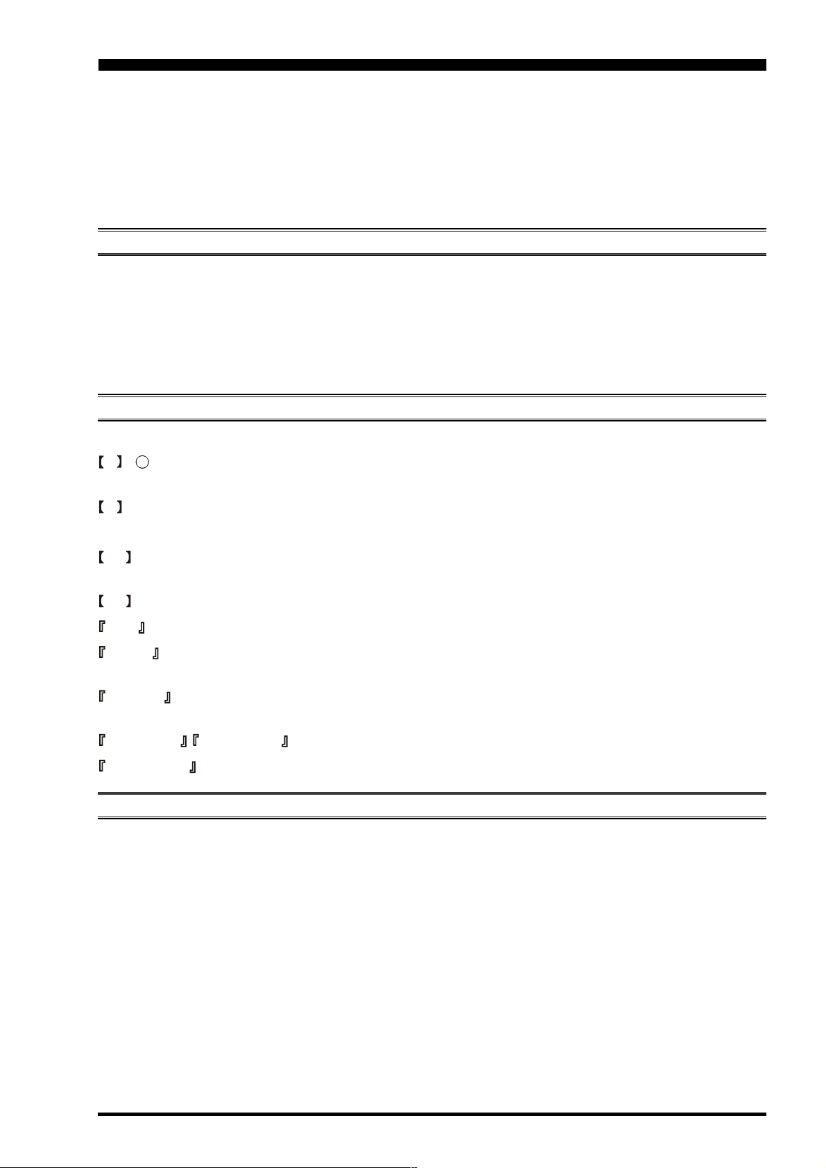
There are two power switches on this transceiver, one each on the rear and front panels. If the rear panel’s Power switch is
not turned on, the front panel Power switch will not function.
Ì Push the rear panel’s Power
switch to the I position
to apply power from the
power supply to the OCXO
(Reference Crystal Oven)
and to enable the front panel
power switch.
Ì Press and hold in the front
panel Power switch for two
seconds to turn the transceiver on.
Note
The opening screen will appear on the TFT display, and
the self-check function of the CPU inside the radio will
begin. Then, the µ-Tuning circuitry will receive the data
from the CPU, and it will perform its own self-check, and
will preset itself to the proper settings for the current operating frequency.
While the µ-Tuning circuitry is obtaining the data, the drive
mechanism will move from one end of its range to the
other end (fast), and this will cause a temporary “motor”
noise that can be heard; this, does not represent any trouble
or problem.
When the radio is turned on for the first time, it takes about
50 seconds (from turning the radio on to completing the
self-check) until the radio becomes ready to use; however, from the next time you turn it on, it will take around
10 seconds until the transceiver is ready for full operation.
2. Setting Your Local Time
When first turning on the FT DX 9000, be sure to set the local time to match your location's time zone. If you do not do this,
several functions will not work correctly, including the World Clock, Great Circle Map, etc.; please see the appropriate
section of the TFT Operating Manual for details on Local Time Setup.
3. Configuring Your FT DX 9000 Using the Menu
The FT DX 9000 is configured, at the factory, with its various functions set up in a manner typical for most operation. Via
the “Menu” system, you may change these settings to match the way you want your transceiver to operate.
Menu programming is enabled by pressing the MNU
(Menu) key momentarily. You may then rotate the Main
Tuning Dial to display the desired Menu item, in the menu
list, on the TFT. Each of the settings can be changed or
customized via the CLAR/VFO-B knob, as you like, in
this mode.
Once you have made a change to the configuration of a
Menu item or items, you must press and hold in the
MNU (Menu) key for two seconds to save the new set-
tings and exit to normal operation.
If you wish to cancel a change to a Menu item or items,
just press the MNU key momentarily. If you do not press
and hold in the MNU key in for two seconds, any changes
you have made will not be saved.
Main Tuning Dial
MNU key
CLAR/VFO-B Knob
Page 4 FT DX 9000D OPERATION MANUAL
Page 7
Before You Begin. . .
4. Connecting and Selecting the Microphone
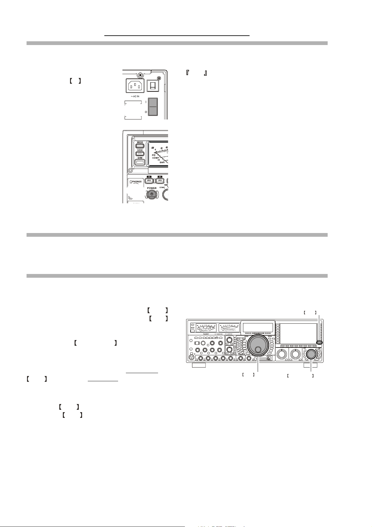
The FT DX 9000D comes equipped with two microphone connectors: the front panel includes a “Cannon” (XLR) three-pin
connector, while the rear panel provides an eight-pin (round) connector.
As shipped from the factory, the front panel XLR connector is engaged for operation, and the rear panel 8-pin microphone
jack is not connected. If you wish to enable the 8-pin connector instead of the XLR connector, use the Menu to accomplish
this. Note that you may leave microphones connected to both jacks, and may select the microphone you want for operation
on a particular operating mode (SSB, AM, FM, etc.), as well!
Ì Press the MNU (Menu) key momentarily to enter
MNU key
the Menu Mode.
Ì Rotate the Main Tuning Dial to select Menu Item
#69, located within the “MODE SSB” group: SSB MIC
SELECT.
Ì Rotate the CLAR/VFO-B knob to change the set-
ting of Menu #069 from “FRONT” to “REAR.”
Ì Press and hold in the MNU (Menu) key for two sec-
onds to save the new setting and exit to normal opera-
“FRONT”
Cannon (XLR)
three-pin connector
Main Tuning Dial
CLAR/VFO-B Knob
tion.
Ì In a similar manner, you may use Menu #040 (AM
MIC SEL) in the MODE-AM Menu Group to select
the microphone jack to be used during AM operation,
and Menu #059 (FM MIC SEL) in the MODE-FM
Menu Group to select the microphone to be used during FM transmission.
“REAR”
8-pin microphone jack
5. Extending the Front Feet
In order to elevate the front panel for easy viewing, the front left and right feet of the bottom case may be extended.
Ì Pull the front legs outward from the bottom panel.
Ì Rotate the legs counter-clockwise to lock them in the
extended position. Be sure the legs have locked securely in place, because the transceiver is quite heavy
and an unlocked leg could result in damage, should
the transceiver move suddenly.
Retracting the Front Feet
Ì Rotate the legs clockwise, and push them inward while
rotating to the right.
Ì The front feel should now be locked in the retracted
position.
EXTEND
RETRACT
Page 5FT DX 9000D OPERATION MANUAL
Page 8
Before You Begin. . .
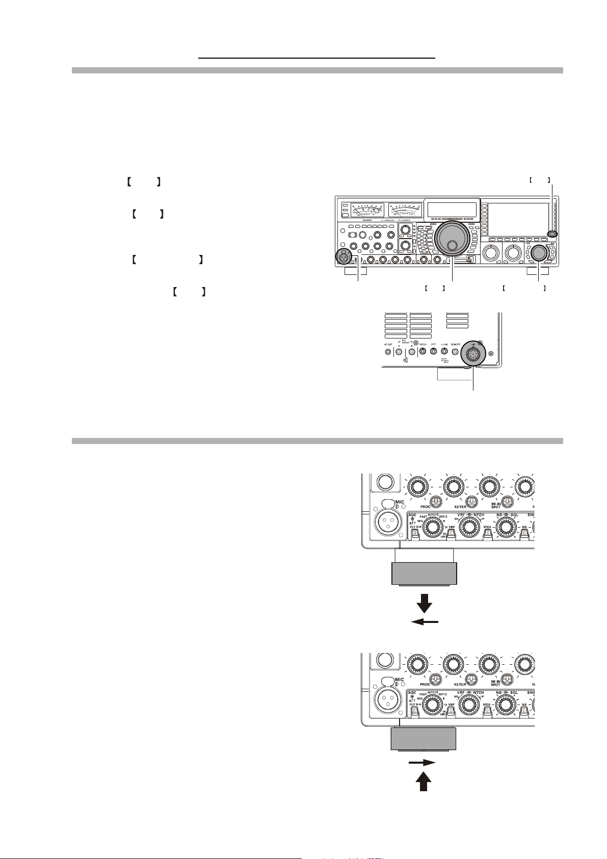
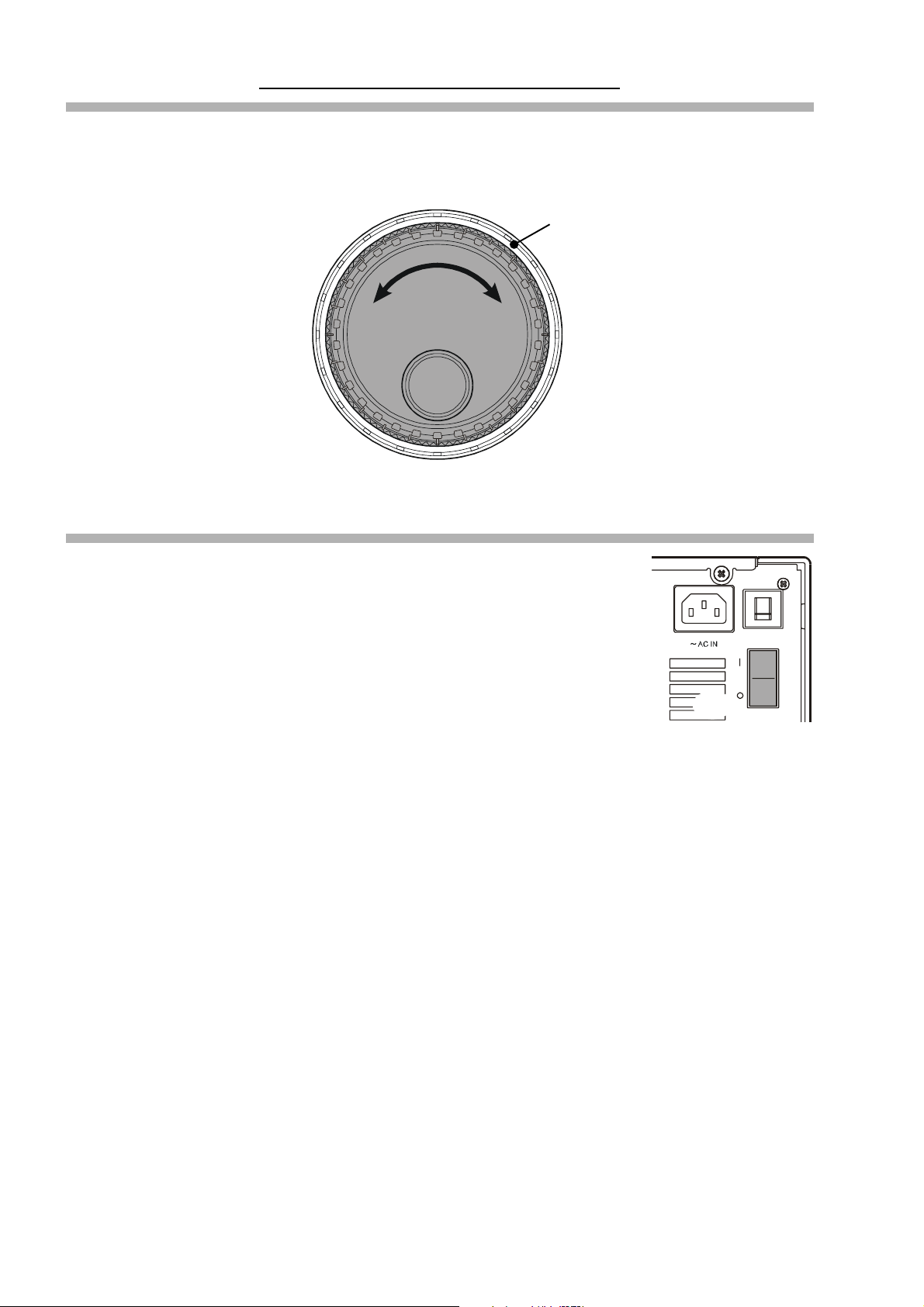
6. Adjusting the Main Dial Torque
The torque (drag) of the Main Tuning Dial may be adjusted according to your preferences. Simply hold down the rear skirt
of the knob, and while holding it in place rotate the Main Dial itself to the right to reduce the drag, or to the left to increase
the drag.
HOLD THE SKIRT
TIGHTEN TOOSEN
7. Restarting Power after a Voltage Fluctuation
If your AC mains power should suffer a significant fluctuation or interruption, we recommend that you go through a complete power-up cycle, in order to ensure that all circuits are
properly initialized. To do this, be sure the front panel Power switch is turned off, then set
the rear-panel Power switch to the “O” position. Now unplug the AC cable from the rear
panel of the transceiver, and wait ten seconds. Plug the AC cable back in, set the rear-panel
Power switch to “O,” and now press and hold in the front-panel Power switch for two seconds to turn the transceiver on. After about 50 seconds, all circuits will be initialized, and
normal operation may resume.
Page 6 FT DX 9000D OPERATION MANUAL
Page 9
Before You Begin. . .
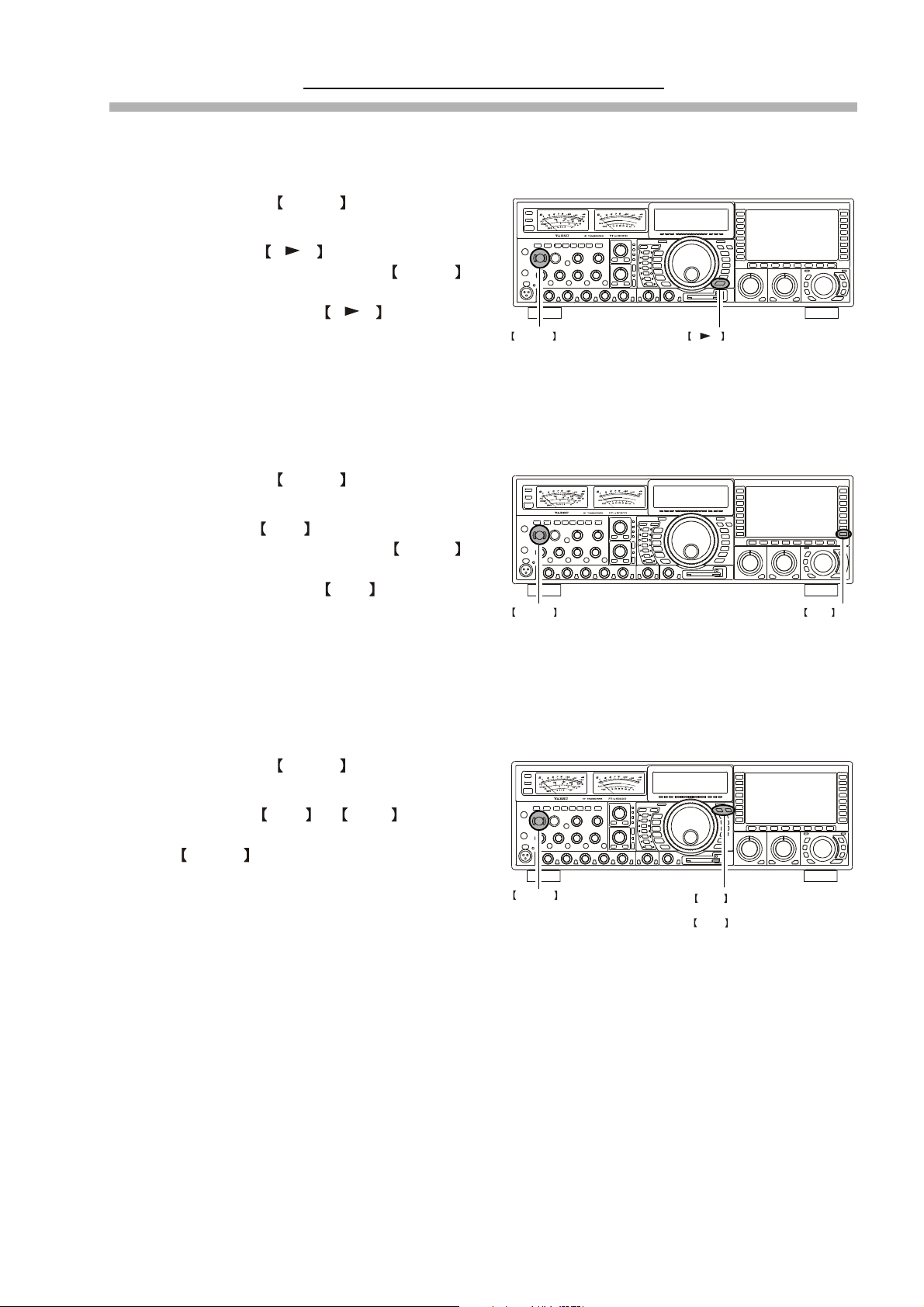
8. Resetting the Microprocessor
Ë Resetting Memories (Only)
Use this procedure to reset (clear out) the Memory channels previously stored, without affecting any configuration changes
you may have made to the Menu settings.
1. Press the front panel’s POWER switch to turn the
transceiver off.
2. Press and hold in the A M switch; while holding
it in, press and hold in the front panel’s POWER
switch to turn the transceiver on. Once the transceiver
comes on, you may release the A M switch.
POWER switch
Ë Menu Resetting
Use this procedure to restore the Menu settings to their factory defaults, without affecting the memories you have programmed.
1. Press the front panel’s POWER switch to turn the
transceiver off.
A M switch
2. Press and hold in the MNU (Menu) key; while holding it in, press and hold in the front panel’s POWER
switch to turn the transceiver on. Once the transceiver
comes on, you may release the MNU (Menu) key.
POWER switch
MNU key
Ë Full Reset
Use this procedure to restore all Menu and Memory settings to their original factory defaults. All Memories will be cleared
out by this procedure.
1. Press the front panel’s POWER switch to turn the
transceiver off.
2. Press and hold in the FAST and LOCK switches;
while holding them in, press and hold in the front
panel’s POWER switch to turn the transceiver on.
Once the transceiver comes on, you may release the
other two switches.
POWER switch
FAST switch
&
LOCK switch
Page 7FT DX 9000D OPERATION MANUAL
Page 10

FEATURES
Superior Visibility and Logical, Fatigue-reducing Panel Layout
The front panel layout is logically crafted, with the large-aperture main frequency display squarely in the middle of the front panel; the
two large S-meters to the left providing instant recognition of signal strength.
Just as in an aircraft cockpit, the panel meters and the TFT are canted slightly toward the center for maximum visibility.
Large, Multi-colored VFD Fluorescent Display
A proprietary, high-brightness VFD (fluorescent) display is incorporated in the FT DX 9000D, providing outstanding visibility (superior even to the TFT) and easy reading of the important frequency information, whether in dim or bright lighting environments.
Function-Indicating LEDs
The many function status indications on the front panel are clearly identified by the operator, thanks to the innovative multi-color LEDs
incorporated in design. A Red LED indicates that a function is engaged on the Main Band, while an Orange LED shows that the function
is engaged on the Sub Band.
Indirect Illumination
For ease of nighttime operation, the controls on the front panel are indirectly illuminated, thanks to carefully-positioned lamps in the
frame underneath the meters and TFT (depending on model).
Aluminum-Die-Cast Oversized Main Tuning Dial
The Main Tuning Dial is a large-diameter (3.2”/81 mm) dial directly coupled to the magnetic rotary encoder which drives the HRDDS
via microprocessor control. Its heavy weight (7 oz./200 g) and quality mounting and construction provide a smooth “flywheel” effect
during operation, ideal for quick cruising up and down a band.
Oversized Knobs for Most Important Functions
The concentric AF/RF Gain, SHIFT/WIDTH, and CLAR/VFO-B knobs are conveniently located right below the TFT, for ease of access
to these important controls.
World’s First 400 MHz HRDDS Local Oscillator
So as to optimize spurious-free dynamic range in a multi-signal environment, Yaesu’s engineers have introduced the world’s first
HRDDS (High Resolution Direct Digital Synthesizer) as the first local oscillator of the FT
frequency, this local oscillator design ensures extraordinarily low noise, resulting in improved weak-signal reception even on a crowded
band during a weekend contest.
DX 9000D. Dividing directly from this high
New-design Large-area OCXO Reference Oscillator
Serving as the master reference oscillator for the transceiver, the 10 MHz OCXO (Oven Controlled Crystal Oscillator) is a large-area (50
x 50 mm/2” x 2”) oven-stabilized oscillator operating at high temperature, for industry-leading frequency stability rated at 0.03 ppm
over the temperature range –10° to +60° C (–14° to +140° F).
Triple-conversion Design with Optimized Gain Distribution
Taking into account the most efficient transceiver design concept consistent with high performance we have adopted a triple-conversion IF
structure, utilizing a first IF at 40 MHz, a second IF at 455 kHz, and the third IF at 30 kHz (for FM, the 3rd IF is at 24 kHz). Gain distribution
through all stages is carefully optimized, for preservation of high system dynamic range.
Ultra-strong Receiver Front End
YAESU’s outstanding RF-stage filtering establishes a clean performance that allows the rest of the receiver to perform at a high level. By
reducing the ingress of energy from very strong sources like Shortwave Broadcast, local AM/FM/TV stations, and other signal sources,
the overall purity of the spectrum delivered to the RF Amplifier first mixer, and subsequent stages is maintained, and the system
Blocking Dynamic Range is also enhanced.
Large, Multi-function Color TFT Display
The 800 x 480 dot, 6.5” TFT display is loaded with information that enhances operation of your FT DX 9000D. Besides general status
information, the TFT includes an Audio Scope (both audio spectrum and “Waterfall” displays) and Oscilloscope page, an RF Spectrum
Scope, a Log Book, Swept-Frequency SWR along with PA Temperature, Bias Level, and Voltage, Memory Channel List, World Clock
with Grey Line display, and a Great Circle Map centered on your location, plus direction indication and control of Yaesu Rotators!
Compact Flash (CF) Card for Data Management
A Compact Flash card is supplied with every FT DX 9000D, for preservation of transceiver configuration settings along with Log Book
archival data.
Professional-Grade Cannon (XLR) Microphone Connector
The FT DX 9 000D incorporates, for the first time ever in an Amateur Radio transceiver, a balanced-input “Cannon” (XLR) microphone connector on
the front panel, for use with studio-grade professional microphones. A round 8-pin microphone jack is also provided on the rear panel.
Two High-precision Analog Meters (Page 29)
The FT DX 9000D incorporates two large (3.4”/86 mm) high-precision analog meters, for the utmost accuracy in measuring transceiver
performance. Visibility is enhanced by the oversized meter scales, making the meters easy to read at all times.
Page 8 FT DX 9000D OPERATION MANUAL
Page 11

FEATURES
Separated Clarifier Display (Page 46, 95)
A clearly-separated display window within the main frequency display area contains receiver and/or transmitter frequency offset ("Clarifier") data, for quick comprehension by the operator.
YAESU Custom-designed 32-Bit Floating Point IF DSP (Page 60)
The new IF DSP system, utilizing a TI TMS320C6711 device, is a high-speed 32-bit floating point circuit designed with a unique
objective: to do away with the “digital” sound of many DSP filtering systems, and emulate the “Analog Sound” so familiar and comfortable to HF DX and Contest operators. The result is a leading-edge receiver that has the “feel” of a traditional analog receiver, but with
the flexibility and superb filtering capability of a modern digital filtering system.
New Mu (µ) Narrow-bandwidth High-Q RF Filters Using Large-Diameter (28 mm) Coils (Page 64)
On the 14 MHz and lower Amateur bands, Yaesu’s breakthrough “µ-Tuning” RF preselector filters provide the greatest level of RF
protection ever incorporated into an Amateur Radio transceiver. Utilizing a 1.1” (28 mm) ferrite core stack, driven through a coil
structure, µ-Tuning provides greatly improved RF selectivity, even compared to our VRF (Variable RF Filter) preselector, resulting in an
ultra-strong front end. Insertion of the µ-Tuning filter improves the 3rd-Order Intercept Point by at least 4 dB, and you can operate on
a very crowded band with the utmost confidence in your receiver.
VRF (Variable RF Filter) Preselector Filter (Page 66)
On the 18 MHz and higher Amateur bands, and on 1.8 - 50 MHz on the Sub (VFO-B) band, Yaesu’s robust VRF (Variable RF Filter)
preselector provides a relay-selected RF selectivity much tighter than that afforded by traditional bandpass filter networks. Sealed relays
select heavy-duty inductors and capacitors, providing a tracking RF filter that protects the RF amplifier and following stages from strong
out-of-band energy.
First IF 3 kHz Roofing Filter (Page 25, 67)
In the 40 MHz 1st IF, three selectable roofing filters are provided, in bandwidths of 3 kHz, 6 kHz, and 15 kHz, to protect the following
stages from strong signals that could degrade dynamic range in the first IF amplifier and subsequent stages. The roofing filters are
automatically assigned according to the operating mode, but the operator may override the automatic selections on the fly.
CONTOUR Filter Enhances “Analog Feeling” of DSP Filters (Page 25, 68)
The DSP-based Contour system is a unique five-band filter that may be used to roll off or peak the IF response. It is chiefly useful for
modifying the response of the ultra-sharp DSP filters, allowing you to roll off (or emphasize) certain frequency components. Oftentimes,
the result is that a difficult-to-understand signal suddenly will pop out of the background noise as solid copy.
SLOPED AGC Circuitry (Page 76)
In traditional AGC systems, all signals rising above a certain RF level are then clamped together at the same audio output, so as to
prevent distortion throughout the IF and AF stages. In the FT
provide an AGC response whereby ever-increasing signal strength results in a slightly-louder audio response, still without accompanying distortion. This lets you use your brain to sort out weak signals from strong ones more effectively.
DX 9000D, however, you can engage the “Sloped” AGC capability to
Receiver AF Limiter Circuit (Page 33, 77)
Occasionally a noise burst or a sudden transmission from a loud station may startle you if you have the AF Gain turned up, and may even
damage your hearing temporarily. The FT
on the available audio output power, much like the AGC circuit does in the RF and IF stages.
DX 9000D provides an AF Limiter (AFL) circuit which, once engaged, clamps an upper limit
“Adjacent Channel Encroachment” S-Meter Monitor (Page 33, 78)
When operating CW in a narrow bandwidth like 300 Hz, you may not be aware of the presence of strong stations that may be making it
difficult for others to hear you. In these situations, the “ACM” (Adjacent Channel Monitor) will take over the Sub Receiver, center it on
the Main Receiver frequency, and display
audio through). This alerts you to the situation, and you can QSY or ask the other station to QSY.
± 1.2 kHz of signal activity on the Sub Receiver’s S-meter (without feeding the interfering
Rugged, High-Output Final Amplifier Design (Page 91)
The final amplifier stage of the FT DX 9000D utilizes push-pull SD2931 MOS FET devices in a conservative, high-stability design. The
large-area die-cast aluminum heat sink is monitored thermostatically, and a quiet cooling fan will engage when the heat sink temperature
rises during long periods of high-power transmission.
Ultra-linear Class-A Operation Capability (Page 90)
The FT DX 9000D’s Class-A capability provides ultra-linear amplifier operation at 75 Watts of power output. Typically, 3rd-order IMD
products are suppressed more than 50 dB, while 5th- and higher-order distortion products are at least 70 dB down during Class-A
operation.
Parametric Microphone Equalizer Circuit (Page 88)
For unmatched flexibility in tailoring your microphone’s audio to match your voice, Yaesu’s engineers have incorporated the industry’s
first Three-Band Parametric Microphone Equalizer, which allows you to enhance or suppress frequency components in three different
audio bands. Equalization may be applied independently to microphones attached to the front and rear panel microphone jacks.
Page 9FT DX 9000D OPERATION MANUAL
Page 12
ACCESSORIES
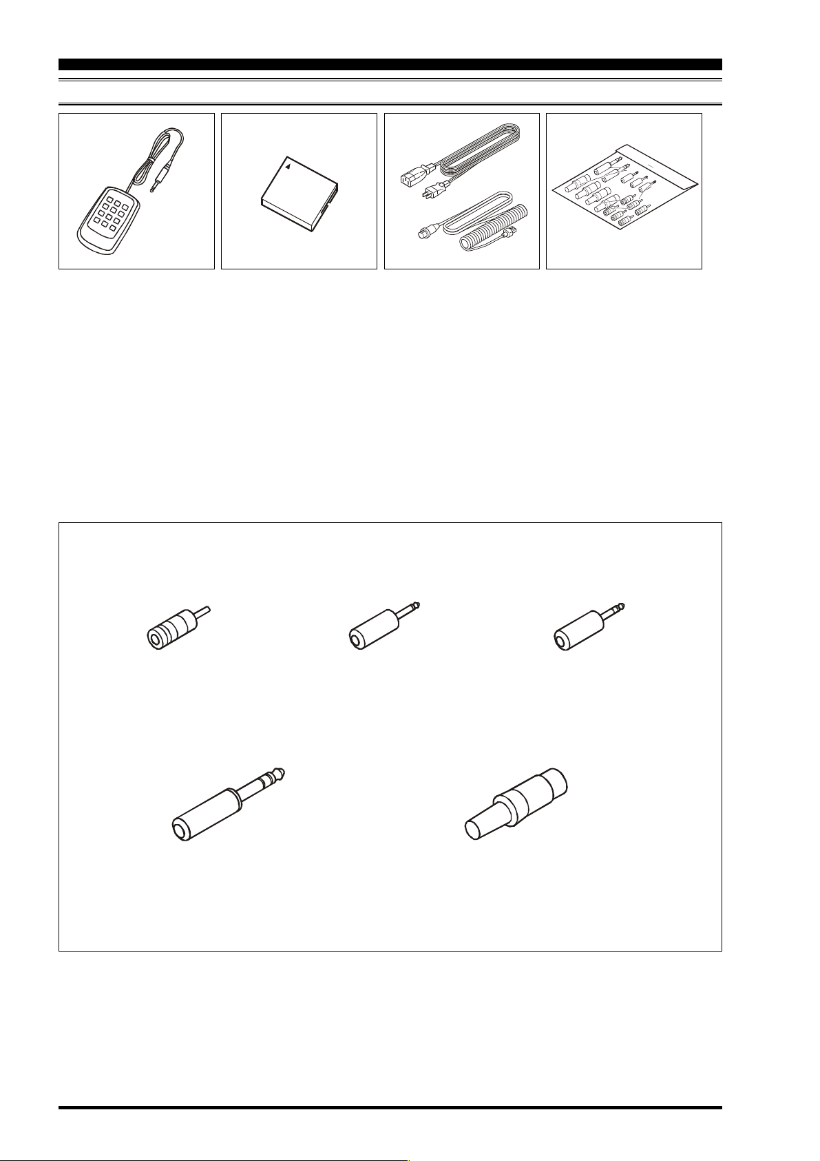
SUPPLIED ACCESSORIES
FH-2
Remote Control Keypad
H Operating Manual
H Warranty Card
RCA Plug (P0091365)
6 pcs
CF Card
(64 MB: Q9000838)
AC Power Cord
Microphone Extend Cable
(8 Pin Modular)
2: AC Power Cord
2: This microphone cable (T9101549) is for use with
Plug Details and Part Numbers
3.5 mm 2-contact Plug
(P0090034)
2 pcs
1
2
USA: T9017882
Europe: T9013285
Australia: T9013283A
UK: T9013285
the optional MD-200A8X, MD-100A8X, or MH-31B8
microphones.
3.5 mm 3-contact Plug
(P0091046)
1 pc
Plugs
1/4-inch 3-contact Plug
(P0090008)
2 pcs
Items are shown for illustrative purposes only, and may vary slightly in appearance.
4-pin DIN Plug (P0091004) 1 pc
5-pin DIN Plug (P0091006) 1 pc
7-pin DIN Plug (P0091419) 1 pc
8-pin DIN Plug (P0090651) 1 pc
Page 10 FT DX 9000D OPERATION MANUAL
Page 13
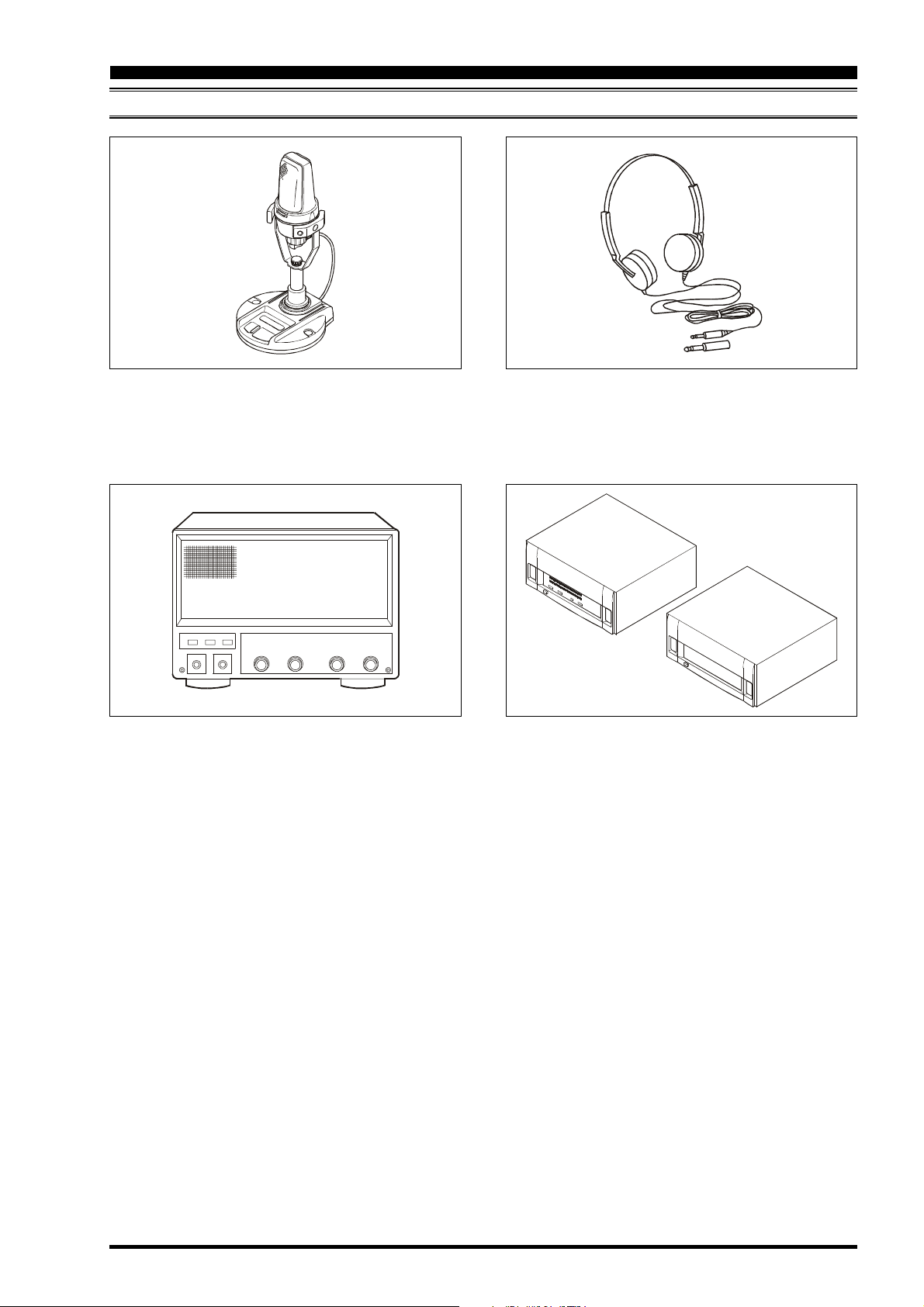
AVAILABLE OPTIONS
MD-200A8X
OPTIONS
Ultra-High-Fidelity Desk-Top Microphone
MD-200A8X
Desk-Top Microphone
MD-100A8X
External Speaker with Dual Speakers and Audio Filter
SP-9000
Lightweight Stereo Headphones
YH-77STA
Linear Amplifier / AC Power Supply
VL-1000 / VP-1000
Page 11FT DX 9000D OPERATION MANUAL
Page 14
INSTALLATION AND INTERCONNECTIONS
ANTENNA CONSIDERATIONS
The FT DX 9000D is designed for use with any antenna system providing a 50 Ohm resistive impedance at the desired
operating frequency. While minor excursions from the 50-Ohm specification are of no consequence, the transceiver’s
Automatic Antenna Tuner may not be able to reduce the impedance mismatch to an acceptable value if the Standing Wave
Ratio (SWR) present at the Antenna jack is greater than 3:1.
Every effort should, therefore, be made to ensure that the impedance of the antenna system utilized with the FT DX 9000D
be as close as possible to the specified 50-Ohm value.
Any antenna to be used with the FT DX 9000D must, ultimately, be fed with 50 Ohm coaxial cable. Therefore, when using
a “balanced” antenna such as a dipole, remember that a balun or other matching/balancing device must be used so as to
ensure proper antenna performance.
The same precautions apply to any additional (receive-only) antennas connected to the RX ANT jack; if your receive-only
antennas do not have an impedance near 50 Ohms at the operating frequency, you may need to install an external antenna
tuner to obtain optimum performance.
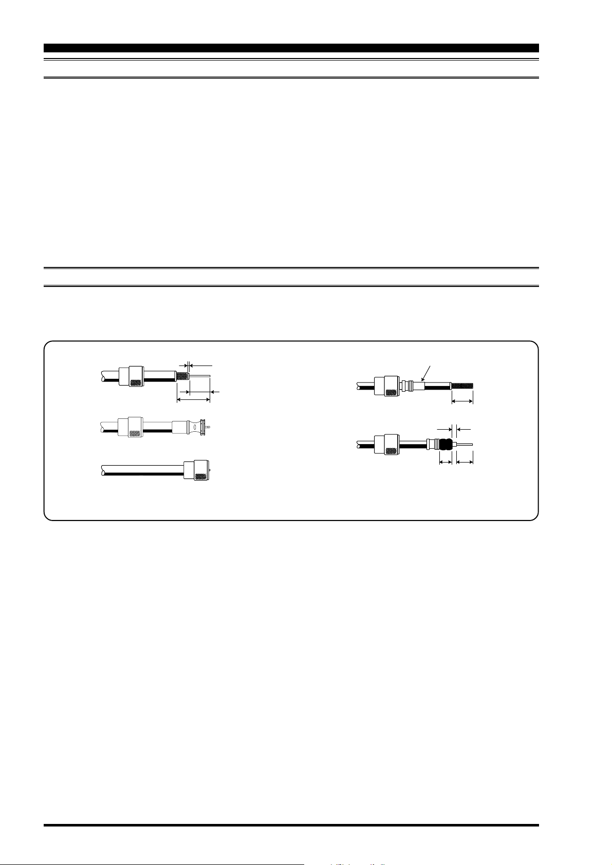
ABOUT COAXIAL CABLE
Use high-quality 50-Ohm coaxial cable for the lead-in to your FT DX 9000D transceiver. All efforts at providing an efficient
antenna system will be wasted if poor quality, lossy coaxial cable is used. This transceiver utilizes standard “M” (“PL-259”)
type connectors, except for the “RX OUT” BNC connectors used for special filters, etc.
1/16"
3/4"
1 1/8"
Adapter
3/4''
1/8''
5/8''3/8''
Typical PL-259 Installation
Page 12 FT DX 9000D OPERATION MANUAL
Page 15
INSTALLATION AND INTERCONNECTIONS
GROUNDING
The FT DX 9000D HF transceiver, like any other HF communications apparatus, requires an effective ground system for
maximum electrical safety and best communications effectiveness. A good ground system can contribute to station efficiency in a number of ways:
Ì It can minimize the possibility of electrical shock to the operator.
Ì It can minimize RF currents flowing on the shield of the coaxial cable and the chassis of the transceiver; such currents
may lead to radiation which can cause interference to home entertainment devices or laboratory test equipment.
Ì It can minimize the possibility of erratic transceiver/accessory operation caused by RF feedback and/or improper cur-
rent flow through logic devices.
An effective earth ground system make take several forms; for a more complete discussion, see an appropriate RF engineering text. The information below is intended only as a guideline.
Typically, the ground connection consists of one or more copper-clad steel rods, driven into the ground. If multiple ground
rods are used, they should be positioned in a “V” configuration, and bonded together at the apex of the “V” which is nearest
the station location. Use a heavy, braided cable (such as the discarded shield from type RG-213 coaxial cable) and strong
cable clamps to secure the braided cable(s) to the ground rods. Be sure to weatherproof the connections to ensure many
years of reliable service. Use the same type of heavy, braided cable for the connections to the station ground bus (described
below).
Inside the station, a common ground bus consisting of a copper pipe of at least 25 mm (1”) diameter should be used. An
alternative station ground bus may consist of a wide copper plate (single-sided circuit board material is ideal) secured to the
bottom of the operating desk. Grounding connections from individual devices such as transceivers, power supplies, and
data communications devices (TNCs, etc.) should be made directly to the ground bus using a heavy, braided cable.
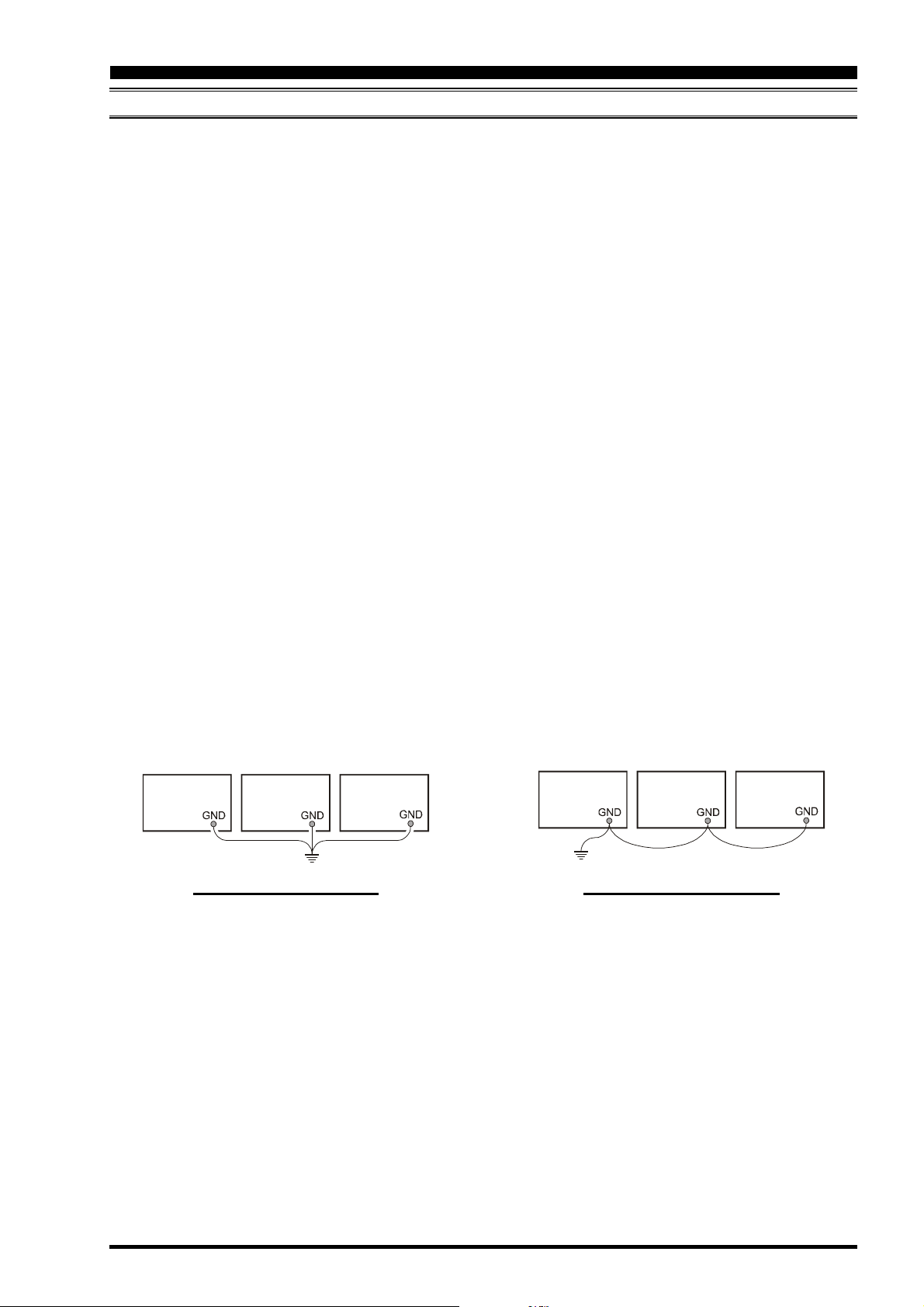
Do not make ground connections from one electrical device to another, and thence to the ground bus. This so-called “DaisyChain” grounding technique may nullify any attempt at effective radio frequency grounding. See the drawing below for
examples of proper grounding techniques.
Inspect the ground system - inside the station as well as outside - on a regular basis so as to ensure maximum performance
and safety.
Besides following the above guidelines carefully, note that household or industrial gas lines must never be used in an
attempt to establish an electrical ground. Cold water pipes may, in some instances, help in the grounding effort, but gas lines
represent a significant explosion hazard, and must never be used.
Transceiver
PROPER GROUND CONNECTION IMPROPER GROUND CONNECTION
Linear
Amplifier
Power
Supply
Transceiver Linear
Amplifier
"Daisy Chain"
Power
Supply
Page 13FT DX 9000D OPERATION MANUAL
Page 16
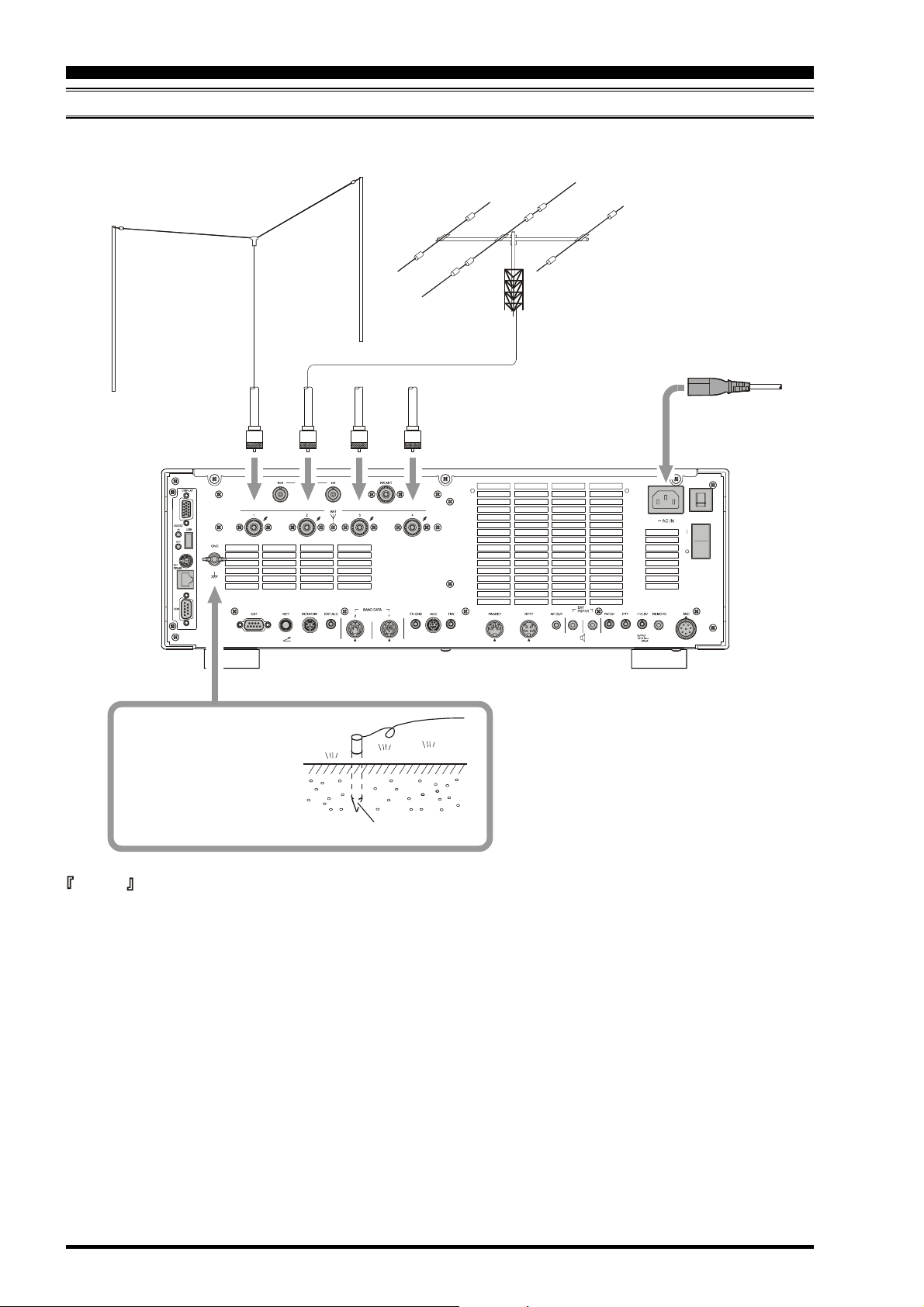
INSTALLATION AND INTERCONNECTIONS
CONNECTION OF ANTENNA AND POWER CABLES
Please follow the outline in the illustration regarding the proper connection of antenna coaxial cables, as well as the AC
power cable.
ANTENNA "1"
ANTENNA "2"
ANTENNA "3"
ANTENNA "4"
AB
Use a short, thick, braided
cable to connect your station equipment to the buried ground rod (or alternative earth ground system).
Ground Rod
Advice
G Do not position this apparatus in a location with direct exposure to sunshine.
G Do not position this apparatus in a location exposed to dust and/or high humidity.
G Ensure adequate ventilation around this apparatus, so as to prevent heat build-up and possible reduction of performance
due to high heat.
G Do not install this apparatus in a mechanically-unstable location, or where objects may fall onto this product from
above.
G To minimize the possibility of interference to home entertainment devices, take all precautionary steps including sepa-
ration of TV/FM antennas from Amateur transmitting antennas to the greatest extent possible, and keep transmitting
coaxial cables separated from cables connected to home entertainment devices.
G Ensure that the AC power cord is not subject to undue stress or bending, which could damage the cable or cause it to be
accidentally unplugged from the rear panel AC input jack.
G Be absolutely certain to install your transmitting antenna(s) such that they cannot possibly come in contact with TV/FM
radio or other antennas, nor with outside power or telephone lines.
Page 14 FT DX 9000D OPERATION MANUAL
Page 17
INSTALLATION AND INTERCONNECTIONS
C
ONNECTION OF MICROPHONE
This transceiver was shipped from the factory in configuration for a microphone input via the Front Panel XLR
connector. To use the Rear Panel microphone with an 8-pin round connector, please change the microphone set up
via the Menu.
1. To do this, first press the MNU key located an the bottom right corner of the TFT display.
2. The Menu list will appear on the TFT display screen.
3. Rotate the Main tuning dial (VFO-A) to select menu item #069 (MODE-SSB 069 SSB MIC SELECT).
4. Now rotate the CLAR/VFO-B knob to change the setting to Rear.
Available selections are FRONT-REAR-DATA-PC.
5. To save the set-up, press and hold in the MNU key for 2 seconds.
If the MNU key is not held for 2 seconds, the set-up will not be saved.
Note : To use the AM or FM mode, please select Menu items 040 for AM and 059 for FM, and follow the same
procedure above.
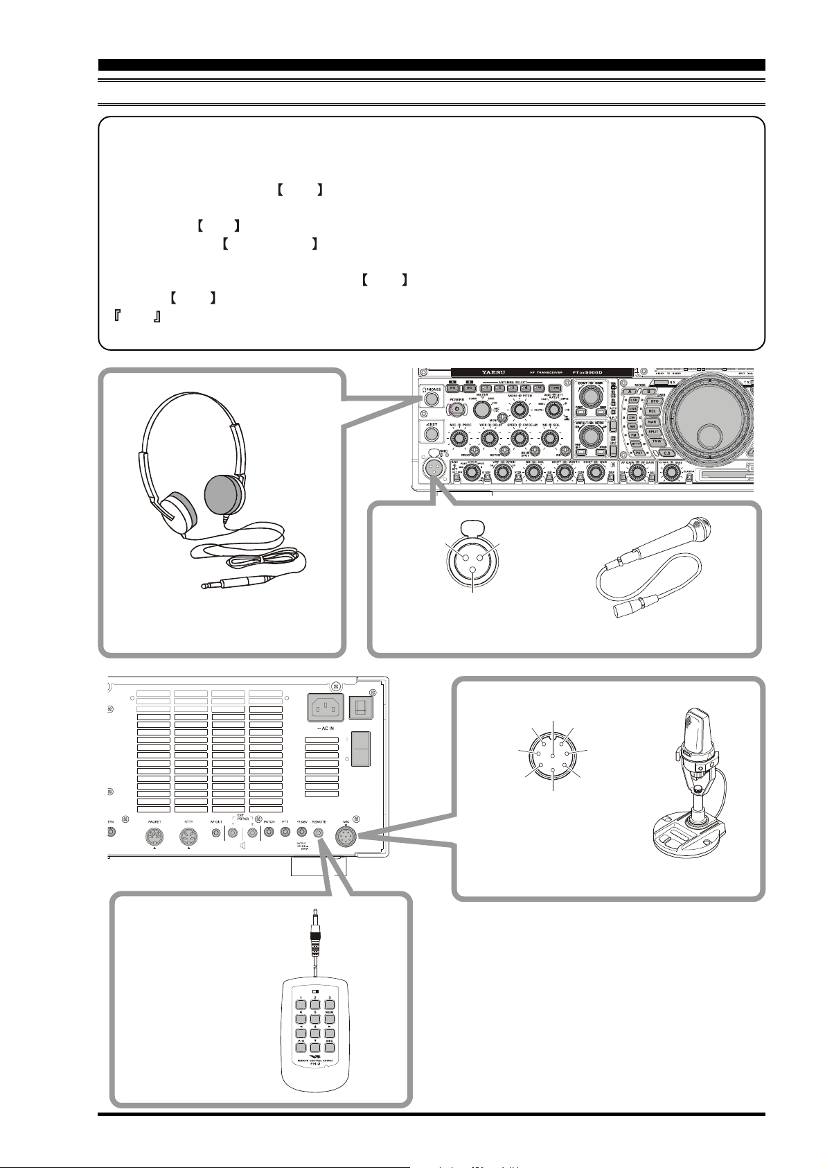
, H
EADPHONES AND
FH-2 R
EMOTE CONTROL KEYP AD
1/4-inch 3-contact jack
Stereo Headphones
②
MIC-Hot
①
MIC-GN D
③
MIC-Cold
XLR connector Type Microphone
MIC⑧
⑦
①
UP
②
+5V
③
DOWN
④
8-pin Connector Type Microphone
MIC GND
⑤
FAST
⑥
PTT
GND
FH-2 Remote Control
Keypad
LOCK
OFFON
Page 15FT DX 9000D OPERATION MANUAL
Page 18
INSTALLATION AND INTERCONNECTIONS
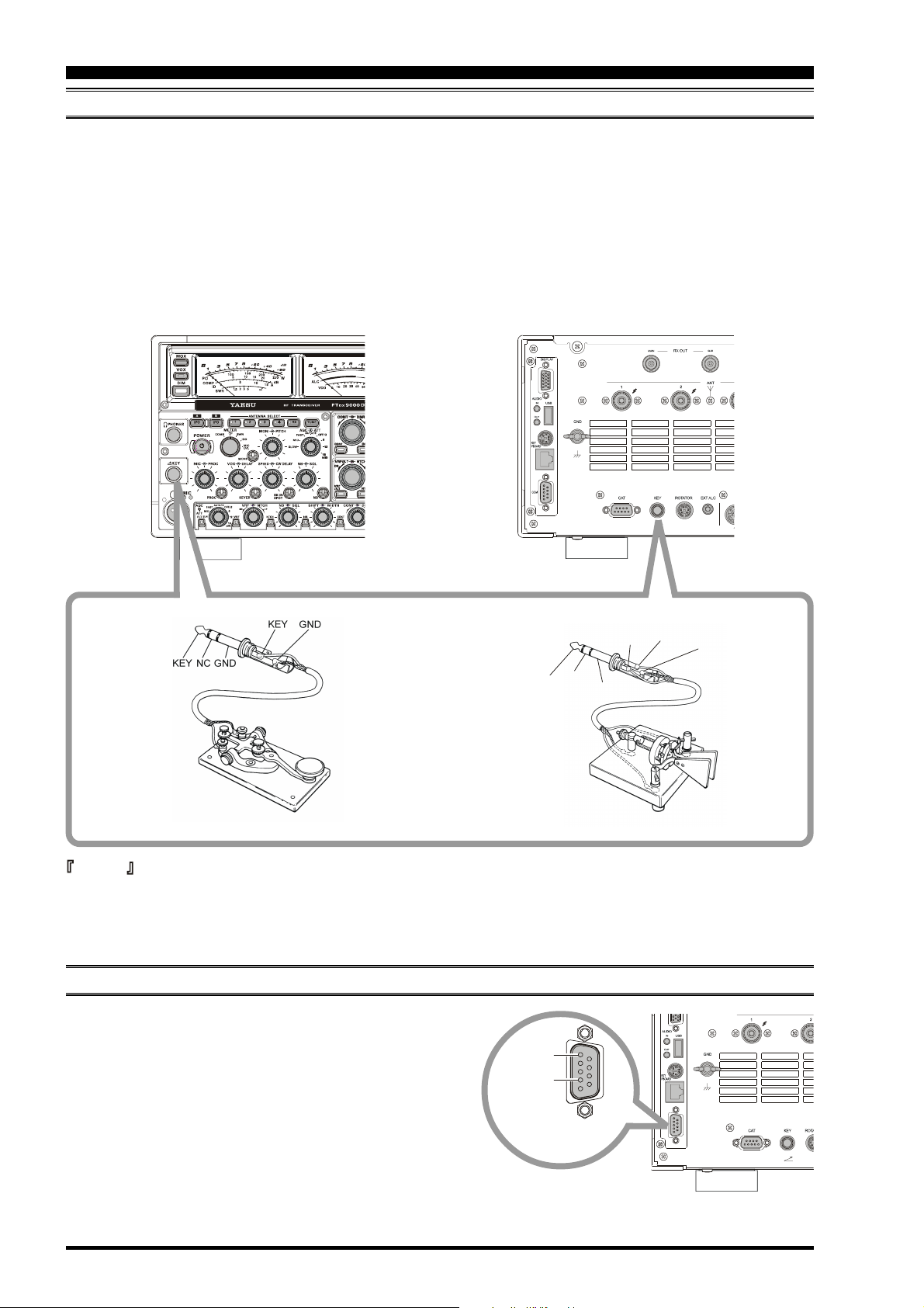
KEY, KEYER, AND COMPUTER-DRIVEN KEYING INTERCONNECTIONS
The FT DX 9000D includes a host of features for the CW operator, the functions of which will be detailed in the “Operation”
section later. Besides the built-in Electronic Keyer, two key jacks are provided, one each on the front and rear panels, for
convenient connection to keying devices.
The Menu system allows you to configure the front and rear panel KEY jacks according to the device you wish to connect.
For example, you may connect your keyer paddle to the front panel KEY jack, and use Menu #041 for paddle input, while
connecting the rear panel’s KEY jack to the keying line from your personal computer (which emulates a “straight key” for
connection purposes), and configure the rear panel jack using Menu #43.
Both KEY jacks on the FT DX 9000D utilize “Positive” keying voltage. Key-up voltage is approximately +5V DC, and keydown current is approximately 1 mA.
DASH
DOT
DASH
DOT
Advice
When connecting a key or other device to the KEY jacks, use only a 3-pin (“stereo”) 1/4” phone plug; a 2-pin plug will
place a short between the ring and (grounded) shaft of the plug, resulting in a constant “key-down” condition in some
circumstances.
COMMON
COMMON
CONNECTING A GPS RECEIVER
If you connect a properly-equipped after-market GPS receiver (not supplied) to the COM port on the back of the
transceiver, the “Rotator” page on the TFT display will automatically include a Great Circle map centered on your
location.
Pin 5
GND
Pin 2
GPS DATA IN
Connect a GPS receiver capable of output of NMEA-0183
data to the COM port. The data line connects to Pin 2, and
the ground shield connects to Pin 5.
This transceiver can support the GGA, GLL, and RMC Data
Sentences from the GPS unit.
Page 16 FT DX 9000D OPERATION MANUAL
Page 19
INSTALLATION AND INTERCONNECTIONS
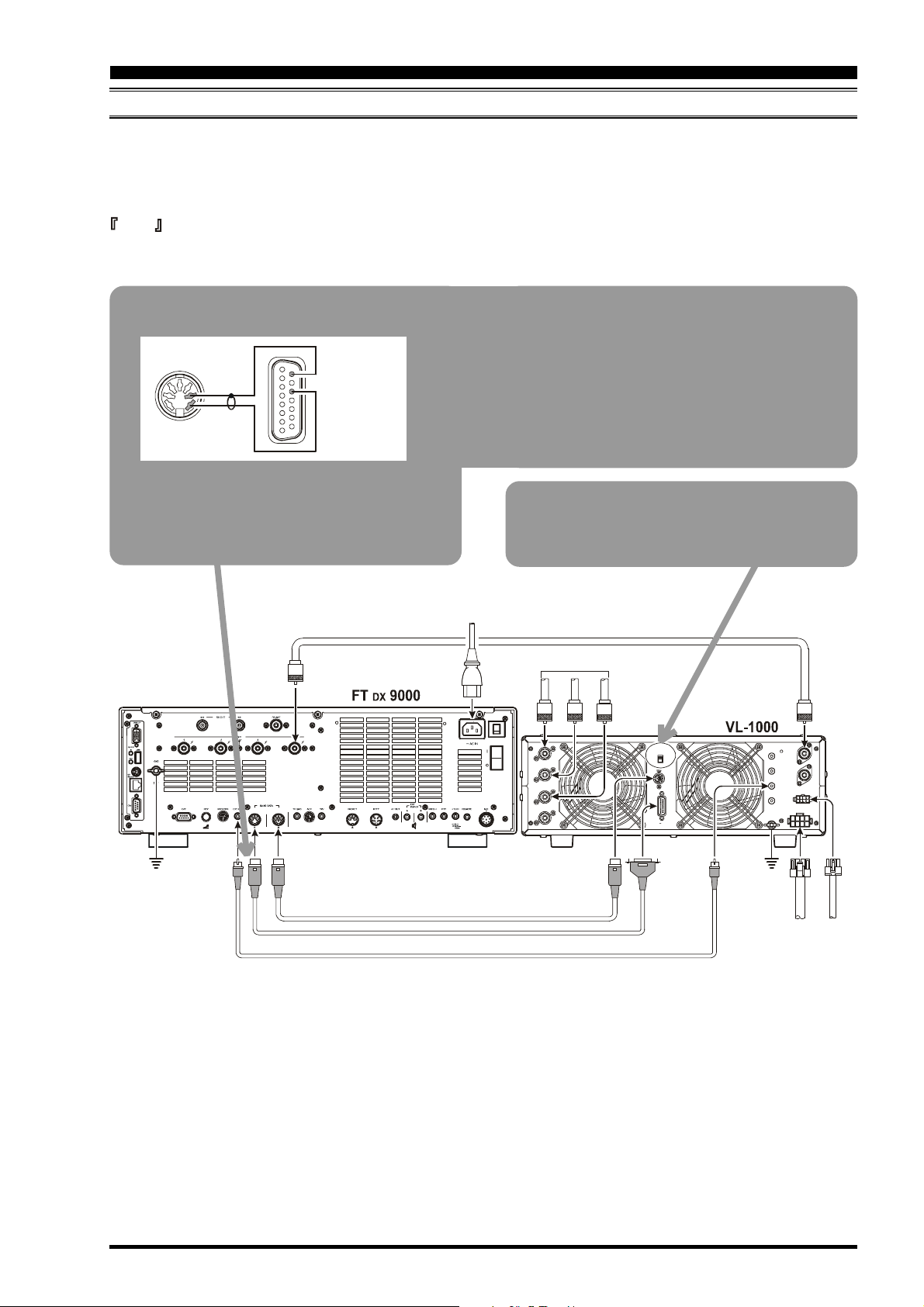
VL-1000 LINEAR AMPLIFIER INTERCONNECTIONS
Be sure that both the FT DX 9000D and VL-1000 are turned off, then follow the installation recommendations contained in
the illustration.
On the rear panel of the VL-1000, please set the “ATT” switch to the “ON” position. The 200-Watt power output from the
FT DX 9000D is far in excess of what is required to drive the VL-1000 to its full rated output.
Note
G Please refer to the VL-1000 Operating Manual for details regarding amplifier operation.
G Please do not attempt to connect or disconnect coaxial cables when your hands are wet.
Control Cable Modification
Pin 9
Pin 3
GND
Pin 7
TRQ
Please cut off the RCA connector on one end of the
CONTROL Cable supplied with the VL-1000, and
install a 7-pin DIN connector in its place, according to the illustration.
21
F SET COMMON
Pin 11
F SET 2
ANT
About the CONTROL Cable
The VL-1000 may be operated with the FT DX 9000D
whether or not the CONTROL Cable is connected;
however, the CONTROL Cable allows you to tune
up the amplifier automatically by just pressing the
[F SET] or [TUNE] key on the VL-1000, so as to
transmit a carrier for tuning purposes.
To link the FT DX 9000D and VL-1000 Power
switches, set the VL-1000 REMOTE switch to the
ON position.
ANTENNA CABLE Supplied w/VL-1000
~AC IN
ANT 1
ANT 2
ANT 3
ANT 4
()
ANTENNA
ANT 1
ANT 2
ANT 3
REMOTE
ON
OFF
BAND DATA 1
BAND DATA 2
INPUT 1
INPUT 1
PTT 1
PTT 2
INPUT 2
ALC 1
CONTROL
ALC 2
DC48V IN
GND
GND
EXT ALC
BAND DATA 2
BAND DATA 1
BAND DATA CABLE
CONTROL CABLE User constructed
ALC CABLE Supplied w/VL-1000
()
Supplied w/VL-1000
()
BAND-DATA 1
()
BAND-DATA 2
ALC 1
GND
DC 48V IN
VP-1000
CONTROL
VP-1000
Page 17FT DX 9000D OPERATION MANUAL
Page 20

INSTALLATION AND INTERCONNECTIONS
INTERFACING TO OTHER LINEAR AMPLIFIERS
ANT 1
GND
ANTENNA CABLE 50
50 MHz
Antenna
ANT 2
EXT ALC
TX GND
(Ω)
~AC IN
HF Antenna
ANT 1
INPUT 1
RF INRF OUT
GND
ACFUSEGND
GND RELAYALC
GND
Note
G The TX/RX switching in the linear amplifier is controlled by switching components in the transceiver. The relay circuit
of the FT DX 9000D used for this switching is capable of switching AC voltage of 100 Volts at up to 300 mA, or DC
voltages or 60 V at 200 mA or 30 V at up to 1 Amp. In order to engage the switching relay, use Menu “TX GNRL 156
EXT AMP TX-GND” within the “TX GNRL” Menu Group; set this Menu selection to “ENABLE” to activate the
amplifier switching relay.
G The specified range for ALC voltage to be used with the FT DX 9000D is 0 to –4 Volts DC.
G Amplifier systems utilizing different voltages will not work correctly with the FT DX 9000D, and their ALC lines must
not be connected if this is the case.
Page 18 FT DX 9000D OPERATION MANUAL
Page 21
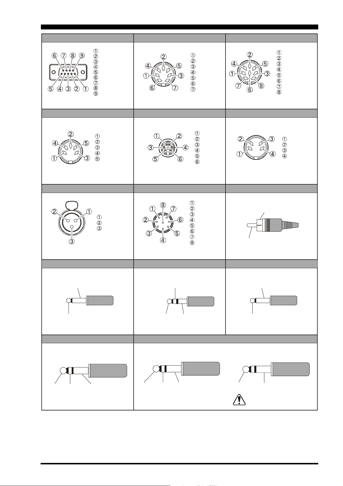
PLUG/CONNECTOR PINOUT DIAGRAMS
CAT
N/A
SERIAL OUT
SERIAL IN
N/A
GND
N/A
N/A
N/A
NC
(as viewed from rear panel)
DATA IN
GND
PTT
DATA OUT
BUSY
(as viewed from rear panel)
MIC XLR
()
MIC-GND
MIC-Hot
MIC-Cold
BAND DATA1
EXT ALC
TX GND
GND
NC
NC
TXINH
FSET
(as viewed from rear panel)
ROTATOR
RT1
RT2
RT3
RT4
GND
NC
(as viewed from rear panel)
MIC
UP
+5V
DOWN
FAST
GND
PTT
MIC GND
MIC
BAND DATA2
+13V
TX GND
GND
BAND DATA A
BAND DATA B
BAND DATA C
BAND DATA D
LINEAR
(as viewed from rear panel)
RTTYPACK ET
RX OUT
PTT
GND
SHIFT
(as viewed from rear panel)
RCA PLUG
GND or
(-)
SIGNAL or
(+)
(as viewed from front panel)
REMOTE
GND
SIGNAL
PHONE
MAIN GND
SUB
(as viewed from rear panel)
AF OUT
SUB VFO-B
()
MAIN GND
()
VFO-A
EXT SPKR
GND
SIGNAL
KEY
For Internal Keyer For Straight Key
DOT DASH COMMON
KEY GND
Do not use
2-conductor type plug
Page 19FT DX 9000D OPERATION MANUAL
Page 22
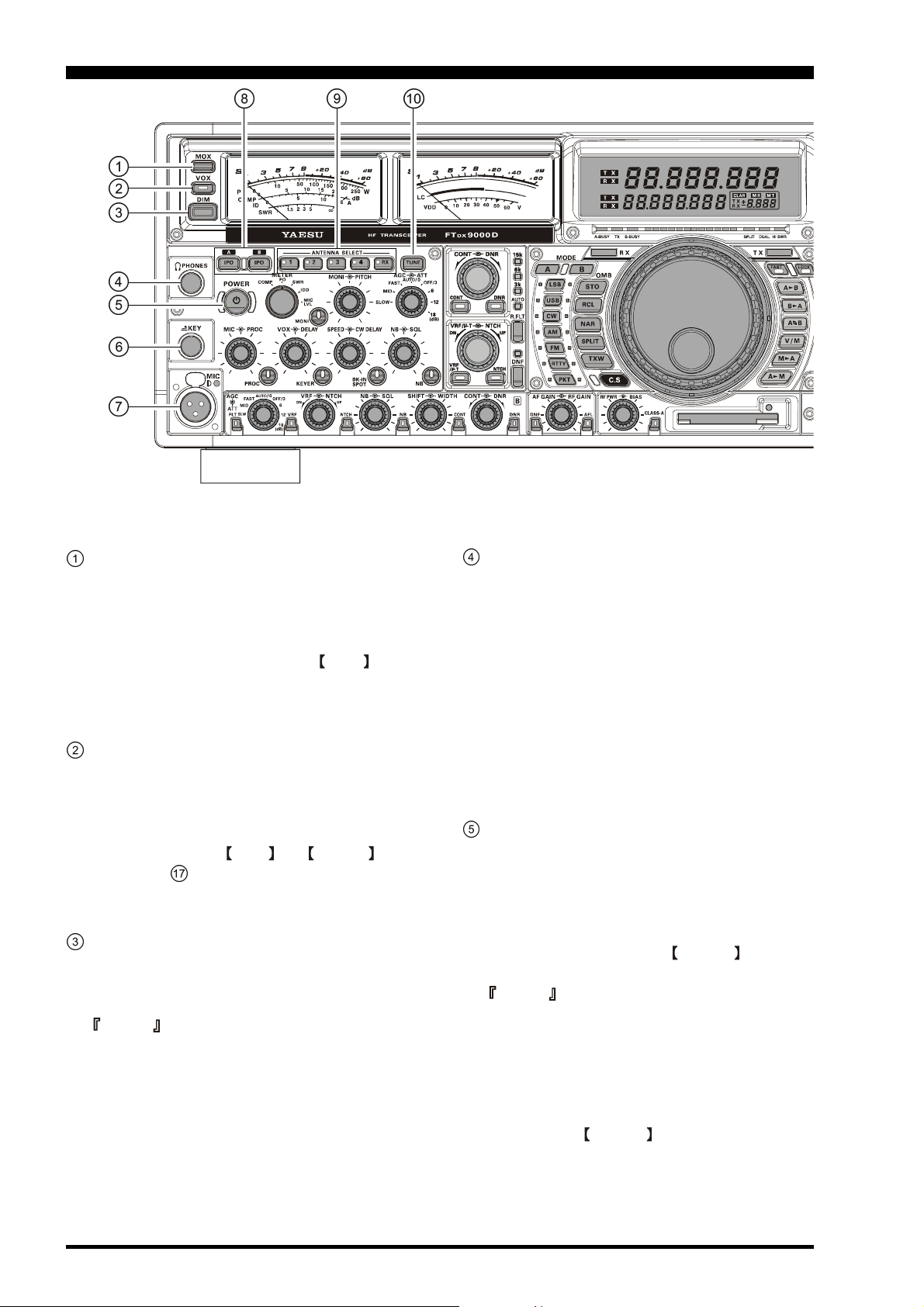
FRONT PANEL CONTROLS
MOX Switch
Pressing this button engages the PTT (Push to Talk)
circuit, to activate the transmitter. It must be in the
undepressed position for reception. This switch replicates the action of the Push to Talk (PTT) switch on
the microphone. When engaging the MOX switch,
or otherwise causing a transmission to be started, be
certain you have either an antenna or 50-Ohm dummy
load connected to the selected Antenna jack.
VOX Switch
VOX Operation: This button enables automatic voiceactuated transmitter switching in the SSB, AM, and
FM modes. While activated, the LED inside this button glows red. The controls affecting VOX operation
are the front panel’s VOX and DELAY knobs
(see section ( ) below. By proper adjustment of these
controls, hands-free voice-actuated operation is possible.
DIM Switch
Press this button to lower the illumination intensity of
the analog meters, the frequency display, and the TFT.
Press it once more to restore full brightness.
Advice
Menu Items “DISPLAY 014 DIMMER-METER” and
“DISPLAY 015 DIMMER-VFD” allow you to configure the dimming levels for the analog meters and
the frequency display/TFT independently, so you can
customize the brightness levels.
PHONES Jack
A 1/4-inch, 3-contact jack accepts either monaural or
stereo headphones with 2- or 3-contact plugs. When a
plug is inserted, the loudspeaker is disabled. With stereo headphones such as the optional YH-77STA, you
can monitor both Main (VFO-A) and Sub (VFO-B)
receiver channels at the same time during Dual Receive operation.
Note: When wearing headphones, we recommend that
you turn the AF Gain levels down to their lowest settings before turning power on, to minimize the impact
on your hearing caused by audio “pops” during switchon.
POWER Switch
Press and hold in this switch for two seconds to turn
the transceiver on, after first setting the rear panel
Power switch to the “I” position. Press and hold in
this switch for two seconds, similarly, to turn the transceiver off. If the rear panel’s Power switch is set to the
“O” position, the front panel POWER switch will
not function.
Advice
This is the actual power On/Off switch for turning on
the transceiver. When the rear panel’s Power switch is
set to the “I” position, power is supplied to the OCXO
to stabilize the reference oscillator, and the remainder
of the transceiver is set in a “stand-by” mode, awaiting the command for the transceiver to switch on via
the front panel POWER switch. For further information on the rear panel Power switch, please see the
discussion on page 36.
Page 20 FT DX 9000D OPERATION MANUAL
Page 23
FRONT PANEL CONTROLS
KEY Jack
This 1/4-inch, 3-contact jack accepts a CW key or
keyer paddles (for the built-in electronic keyer), or
output from an external electronic keyer. Pinout is
shown on page 16. Key up voltage is 5 V, and key
down current is 1 mA. This jack may be configured
for keyer, “Bug,” “straight key,” or computer keying
interface operation via Menu Selection “MODE-CW
041 F-KEYER TYPE (see page 135).” There is another jack with the same name on the rear panel, and
it may be configured independently for Internal Keyer
or pseudo-straight-key operation.
Note
You cannot use a 2-contact plug in this jack (to do so
produces a constant “key down” condition).
Cannon (“XLR”) Microphone Connector
This Cannon-type (XLR) connector accepts input from
the Microphone or other XLR-equipped microphone
system. MIC connector pinout is shown on page 15.
Proper microphone input impedance is 500 ~ 600
Ohms.
If you are using a condenser microphone requiring 48
Volts DC, you may enable this voltage to appear on
the microphone line; see page 81. When the 48-volt
supply line has been enabled, the LED adjacent to the
MIC jack will glow red.
To disconnect the microphone plug, draw out the microphone plug while pressing and holding in the silver push-button.
IPO
(Intercept Point Optimization)
The IPO(A) Lamp-button may be used to set the
optimum receiver front end characteristics of the main
receiver circuit for a very strong-signal environment.
Selecting IPO bypasses the front end RF amplifier and
feeds the received signals directly to the first mixer of
the main band (VFO-A) receiver circuit. While the
IPO feature is activated, this button will remain illuminated.
The IPO(B) Lamp-button, similarly, allows direct
feed of the received signals to the first mixer of the
sub band (VFO-B) receiver circuit. While the IPO
feature is activated on the sub receiver, this button
will be lit.
Advice
The FT DX 9000D’s first mixer is an active type, using
four SST310 Junction FETs. This mixer design provides gain to the receiver chain, so the noise figure of
the receiver is fundamentally lower than with some
other designs. Therefore, it frequently is not necessary to utilize the RF preamplifier, and the receiver
Intercept Point will be substantially increased by engaging IPO, so as to feed the incoming signals directly
to the first (active) mixer. We recommend that IPO be
switched on whenever possible.
Switch
ANTENNA SELECT Switches
These momentary buttons select the antenna jack on
the rear panel, with the selection indicated by the LED
in each button. When an antenna has been selected
for operation on the main band (VFO-A), the LED in
the button glows red. When an antenna has been selected for operation on the sub band (VFO-B), the
LED in the button glows umber.
TUNE Switch
This is the on/off switch for the FT DX 9000D’s Automatic Antenna Tuner.
Pressing this button momentarily places the antenna
tuner in line between the transmitter final amplifier
and the antenna jack (the LED will become illuminated). Reception is not affected.
Pressing and holding in this button for 1/2 second,
while receiving in an amateur band, activates the transmitter for a few seconds while the automatic antenna
tuner rematches the antenna system impedance for
minimum SWR. The resulting setting is automatically
stored in one of the antenna tuner’s 100 memories,
for instant automatic recall later when the receiver is
tuned near the same frequency.
Pressing this button momentarily, while the Tuner is
engaged, will take the Automatic Antenna tuner out of
the transmit line.
Note
When the Automatic Antenna tuner is tuning itself, a
signal is being transmitted. Therefore, be absolutely
certain that an antenna or dummy load is connected to
the selected antenna jack before pressing and holding
in the TUNE button to start antenna tuning.
Page 21FT DX 9000D OPERATION MANUAL
Page 24
FRONT PANEL CONTROLS
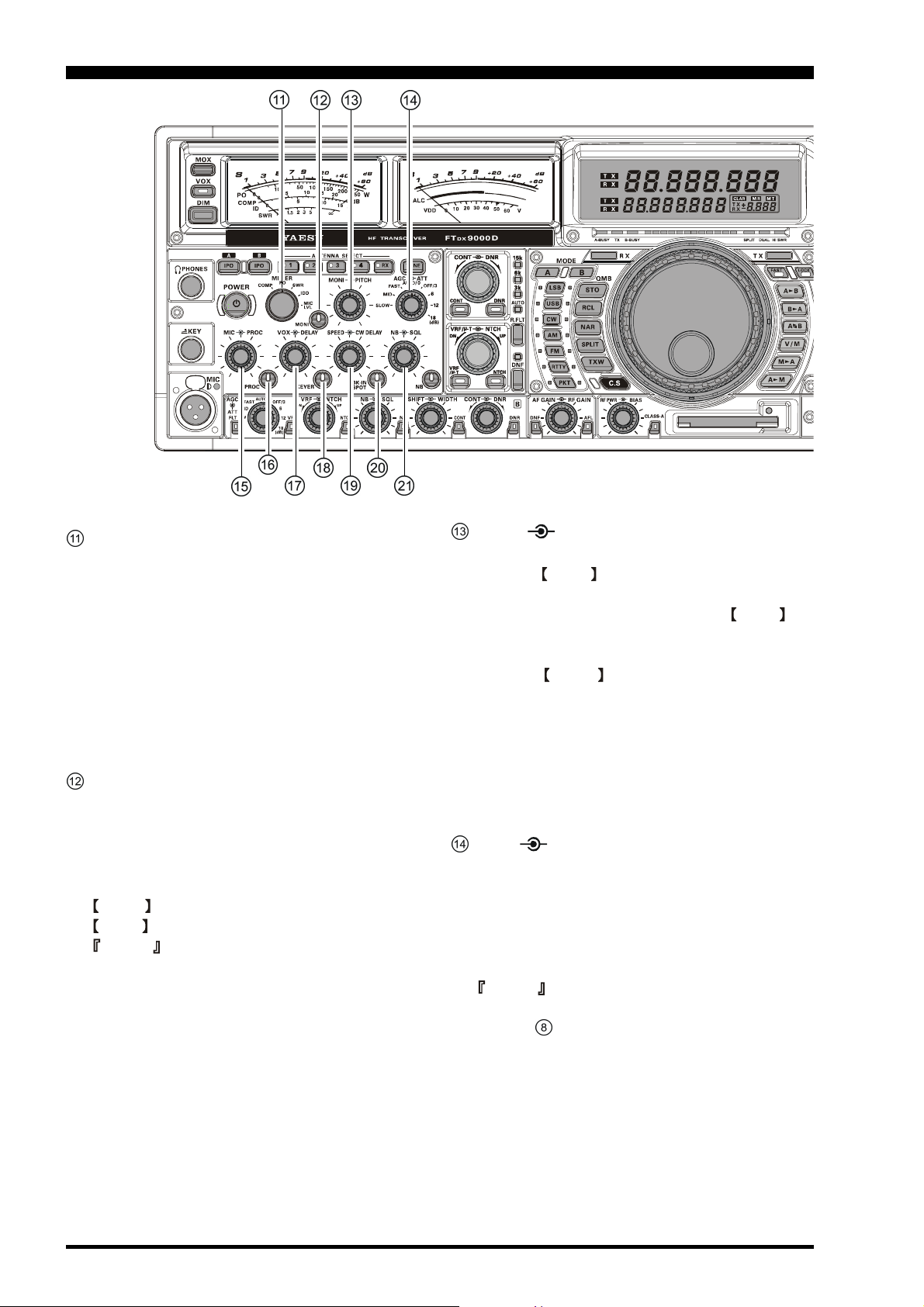
METER Switch
This control switch determines the function of the
Main Meter during transmission.
COMP: Indicates the RF speech compressor
level (SSB modes only).
PO: Indicates the power output level.
SWR: Indicates the Standing Wave Ratio (For-
ward: Reflected).
IDD: Indicates the final amplifier drain cur-
rent.
MIC LVL: Indicates the relative microphone level.
MONI (Monitor) Switch
This button enables the transmit (RF) monitor in all
modes (except CW, in which the monitor function
is always on, to produce the sidetone). While activated, the LED in this button glows red. Adjustment
of the Monitor level is accomplished using the
MONI knob, located just to the right of the
MONI switch.
Advice
When using headphones, the Monitor is highly useful for making adjustments to the Parametric Equalizer or other voice quality adjustments, because the
voice quality heard in the headphones is such a “natural” reproduction of the transmitted audio quality.
MONI PITCH Knobs
MONI Knob
The inner MONI knob adjusts the audio level of the
transmit RF monitor during transmission (relative to the
AF GAIN control), when activated by the MONI button (above).
PITCH Knob
The outer PITCH knob selects your preferred CW
tone pitch (from 300 ~ 1000 Hz, in 50 Hz increments).
The Tx sidetone, receiver IF passband, and display offset from the BFO (carrier) frequency are all affected
simultaneously. The Pitch control setting also affects
the operation of the CW Tuning Indicator, as the center
frequency of the CW Tuning Indicator will follow the
setting of this control.
AGC ATT Knobs
AGC Knobs
This switch selects the AGC characteristics for the Main
(VFO-A) band receiver.
ATT Knobs
This switch selects the degree of attenuation, if any, to
be applied to the Main (VFO-A) receiver input.
Advice
The Attenuator may be used in conjunction with the IPO
switch (# above) to provide two stages of signal reduction when an extremely strong signal is being received.
Page 22 FT DX 9000D OPERATION MANUAL
Page 25
FRONT PANEL CONTROLS
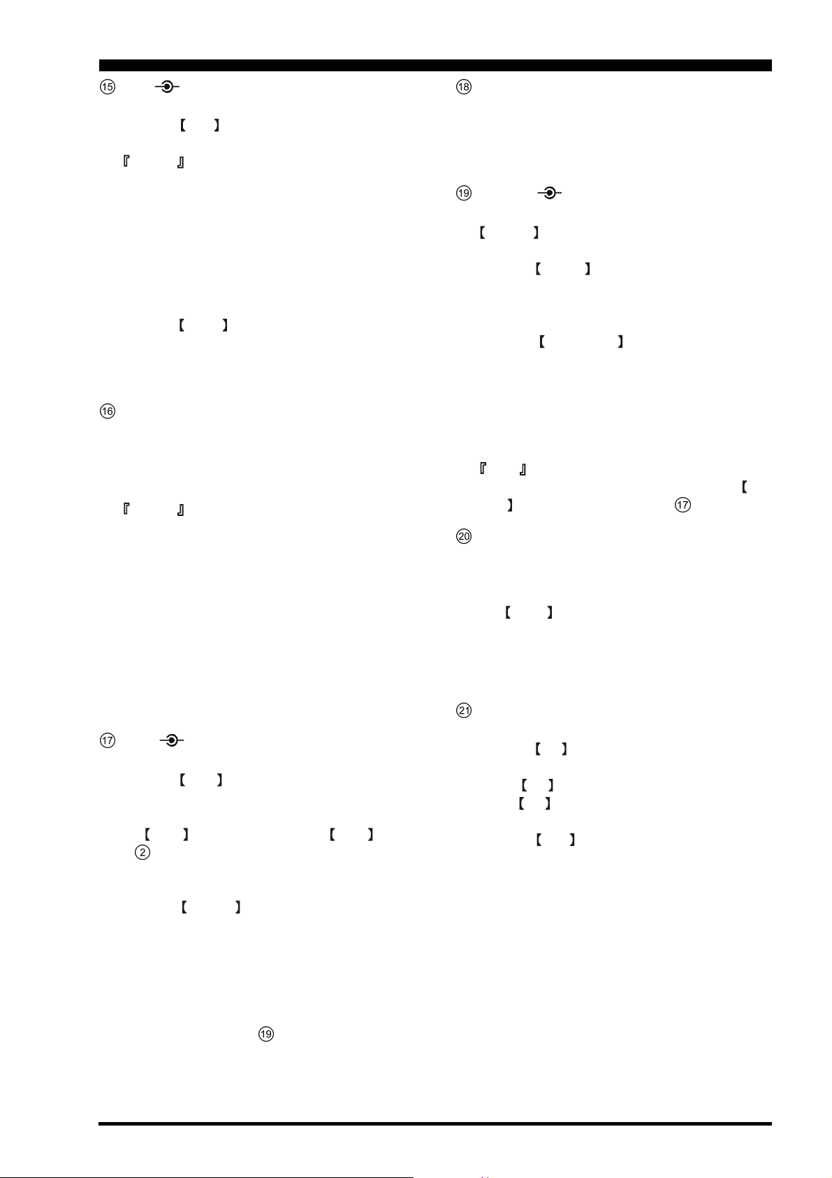
MIC PROC Knobs
MIC Knob
The inner
level for (non-processed) SSB transmission.
Advice
If you adjust the MIC Gain while speaking in a louderthan-normal voice level and watching the ALC level
on the right-side meter, adjust the MIC Gain so that
the ALC reaches over to the right edge of the ALC
scale. Then, when you speak in a more normal voice
level, you’ll be certain not to be over-driving the mic
amplifier stage.
PROC Knob
The outer
level of the transmitter RF speech processor in the
SSB and modes, when activated by the button with
the same name (see next section).
MIC knob adjusts the microphone input
PROC knob sets the compression (input)
PROC (Processor) Switch
This button enables the RF speech processor for SSB
transmission. Processing level is set by the outer control with the same name (see previous section). While
activated, the LED in this button glows red.
Advice
The Speech Processor is a tool for increasing the average power output through a compression technique.
However, if the PROC level control is advanced too
far, the increase in compression becomes counter-productive, as intelligibility will suffer. We recommend
that you monitor the sound of your signal using the
Monitor (with headphones), and watch the Oscilloscope page on the TFT while transmitting (Monitor
must be on), then advance the PROC level only as far
as required to obtain a useful increase in average power
output.
VOX DELAY Knobs
VOX Knob
The inner VOX knob sets the gain of the VOX circuit, to set the level of microphone audio needed to
activate the transmitter during voice operation while
the VOX button is engaged. The VOX switch
(# above) must be switched On to engage the VOX
circuit.
DELAY Knob
The outer DELAY knob sets the hang time of the
VOX circuit, between the moment you stop speaking,
and the automatic switch from transmit back to receive. Adjust this for smooth VOX operation, so the
receiver is only activated when your transmission is
ended and you wish to receive.
For CW operation, you can adjust the keying delay
separately; see control # below.
KEYER Switch
This button toggles the internal CW keyer on and off.
While activated, the LED in this button glows red. The
Keyer sending speed, and the CW Hang Time are adjusted via the controls described in the next section.
SPEED CW DELAY Knobs
The internal Electronic Keyer is activated by the
KEYER switch, described in the previous section.
SPEED Knob
The inner SPEED knob adjusts the keying speed of
the internal CW keyer. Clockwise rotation increases
the sending speed.
CW DELAY Knob
This outer CW DELAY knob sets the hang time of
the CW “VOX” circuit, between the moment you stop
sending, and the automatic switch from transmit back
to receive during “Semi-break-in” operation. Adjust
this just long enough to prevent the receiver from being restored during word spaces at your preferred sending speed. Clockwise rotation increases the hang time.
Note
The SSB VOX hang time is adjusted via the DELAY control described in section above.
BK-IN/SPOT Switches
This button turns the full break-in (QSK) CW capability on and off. While QSK is activated, the LED in
this button glows red.
The SPOT button turns on the CW receiver spotting tone; by matching the SPOT tone to that of the
incoming CW signal (precisely the same pitch), you
will be “zero beating” your transmitted signal on to
the frequency of the other station.
NB/SQL Knobs
NB Knob
The inner NB knob adjusts the noise blanking level
when the (analog) IF noise blanker is activated by pressing the NB button. The Noise Blanker is activated
via the NB switch, described in the next section.
SQL Knob
The outer SQL knob sets the signal level threshold
at which main (VFO-A) receiver audio is muted, in
all modes. It is very useful during local rag-chews, to
eliminate noise between incoming transmissions. This
control is normally kept fully counter-clockwise (off),
except when scanning and during FM operation.
Page 23FT DX 9000D OPERATION MANUAL
Page 26
FRONT PANEL CONTROLS
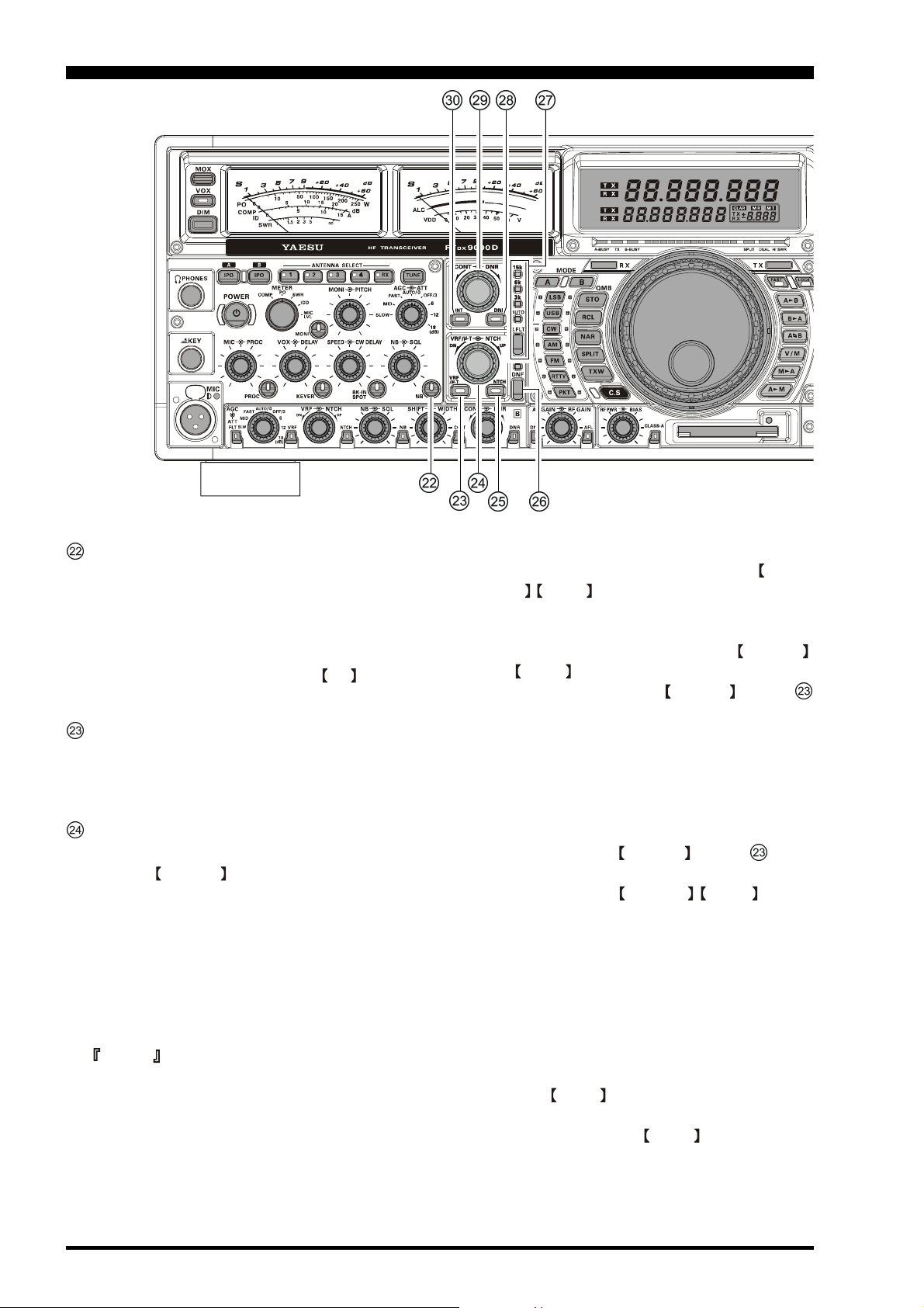
NB Switch
Pressing this button activates the (analog) IF Noise
Blanker, which may help reduce many different types
of man-made impulse noise (but not atmospherics).
When the Noise Blanker is activated, the LED inside
the button will glow red. Adjustment of the Noise
Blanker level is accomplished via the NB knob, described in the previous section.
VRF/µ-T Switch
This button turns the main band (VFO-A) receiver’s
VRF filter or µ-TUNE filter on and off. While activated, the LED inside the button will glow red.
VRF/µ-T/NTCH Knobs
VRF/µ-T Knob
The inner VRF/µ-T knob tunes the passband of the
main band (VFO-A) receiver’s RF filter (18 MHz and
higher Amateur bands) or µ-TUNE filter (Narrowbandwidth High-Q RF Filter) (14 MHz and lower
Amateur bands) for maximum receiver sensitivity (and
out-of-band interference rejection). On the 18 MHz
and higher Amateur bands, this knob provides adjustment of the VRF (Variable RF Filter) preselector circuit.
Advice
H It is possible to use the Menu to de-select the µ-
Tune module, and utilize VRF instead, on bands
where a µ-Tune module is installed. However, the
superior selectivity of the µ-Tune circuit is preferred for most applications.
H The µ-Tune circuitry automatically tracks your op-
erating frequency, and adjustment of its center frequency is normally not required. However, if a
very strong signal within several dizen kHz is
causing you problems, you may use the VRF/µT / NTCH knob to skew the tuning to one side
of the other of your current frequency, to roll off
the strength of the interfering station.
H If you wish to reset the tuning of the VRF/µ-T /
NTCH knob to its original (centered) setting,
just press and hold in the VRF/µ-T switch (#
above) for two seconds. The µ-Tune circuit will
not revert to its normal (automatically tuned) position, centered on your current frequency.
H There is a slight increase in receiver path insertion
loss when the µ-Tune circuit is engaged. On the
frequencies where µ-Tune is used, this is seldom a
problem. If the slight signal loss presents a problem, just turn the VRF/µ-T switch (# above)
Off.
H Rotation of the VRF/µ-T / NTCH knob to
adjust the µ-Tune circuit should be performed only
to optimize the signal or reduce interference. The
µ-Tune circuit tuning is surprisingly sharp. If you
are adjusting VRF, however, the tuning is much
more broad, and we believe that VRF adjustment
will seldom be required.
H The relative position of the µ-Tune or VRF pass-
band can be observed on the TFT display.
NTCH Knob
The outer NTCH knob adjusts the center frequency
of the main band (VFO-A) IF notch filter. The Notch
Filter is engaged via the NTCH switch, described
in the next section.
Page 24 FT DX 9000D OPERATION MANUAL
Page 27
FRONT PANEL CONTROLS
NTCH Switch
This button turns the main band (VFO-A) IF notch
filter on and off. When the IF notch filter is activated,
the LED inside the button will glow red. The Notch
Filter center frequency is adjusted via the NTCH
knob, described in the previous section.
Advice
H The width of the notch may be set to either “Wide”
or “Narrow” via Menu item “RX DSP 082 IFNOTCH-WIDTH” in the RX DSP Menu Group.
Setting this selection to “Narrow” will provide a
very sharp notch, with minimal disturbance to the
incoming signal wave-form.
H The tuning rate of the Notch Filter being rather
slow, it frequently is useful to use the Audio Scope
of the TFT (either the Audio Spectrum Scope or
the Waterfall display) to adjust the center frequency of the IF Notch Filter. In the Waterfall
display mode, the notched area will appear more
white than the background screen, while on the
Audio Spectrum Scope screen the notched area
will appear as a “hole” in the noise.
DNF Switch
This button turns the main band (VFO-A) Digital
Notch Filter on and off. When the Digital Notch Filter is activated, the LED indicator will glow red. This
is an automatic circuit, and there is no adjustment knob
for the DNF.
R.FLT Switch
This button selects the bandwidth for the main band
(VFO-A) receiver's first IF Roofing Filter. Available
selections are 3 kHz, 6 kHz, 15 kHz, or Auto, and the
LED indicator will change according to the bandwidth
selected.
Advice
Because the roofing filter is in the first IF, the protection it provides against interference is quite significant. When set to AUTO, the SSB bandwidth is 6 kHz,
while CW is 3 kHz and FM/RTTY are 15 kHz. On a
crowded SSB band, however, you may wish to select
the 3 kHz filter, for the maximum possible interference rejection.
CONT DNR Knob
CONT Knob
The inner
(VFO-B) CONTOUR filter response. The CONTOUR
filter is engaged via the
the next section.
DNR Knob
The outer DNR knob selects the optimum Main
Band (VFO-A) Digital Noise Reduction response. The
Noise Reduction circuit is engaged via the DNR
switch, described in section above.
CONT knob selects the desired sub band
CONT switch, described in
CONT Button
This button turns the sub band (VFO-B) CONTOUR
filter on and off. When the CONTOUR filter is activated, the LED inside the button will glow umber. Adjustment of the CONTOUR filter’s center frequency
is provided by the CONT knob, described in section above.
Quick Note
There are times, when you’re trying to remove interference with a sharp DSP filter, that the remaining signal has a somewhat unnatural sound. This is caused
by the cutting of some frequency components, leaving other components in excess. The CONTOUR filter allows you (especially) to roll off certain frequency
components inside the remaining passband, but in a
smooth manner that helps restore a natural sound and/
or raise intelligibility.
Advice
H The action of the CONTOUR filter (either null-
ing or peaking of frequency components as you
adjust the center frequency) may be adjusted via
Menu item “RX DSP 079 MAIN-CONTOURWIDTH.” The adjustment range includes settings
of -15 dB (nulling) to +10 dB (peaking).
H The Audio Spectrum Scope (including the Wa-
terfall displays) on the Oscilloscope page of the
TFT can be particularly useful when adjusting the
CONT control (see section above), as you
can observe the position of the null or peak in the
audio passband.
DNR Switch
This button turns the Main band (VFO-A) Digital
Noise Reduction circuit on and off. When the Digital
Noise Reduction is activated, the LED inside the button will glow umber. Adjustment of the Noise Reduction level is provided by the DNR knob, described
in the next section.
Page 25FT DX 9000D OPERATION MANUAL
Page 28
FRONT PANEL CONTROLS
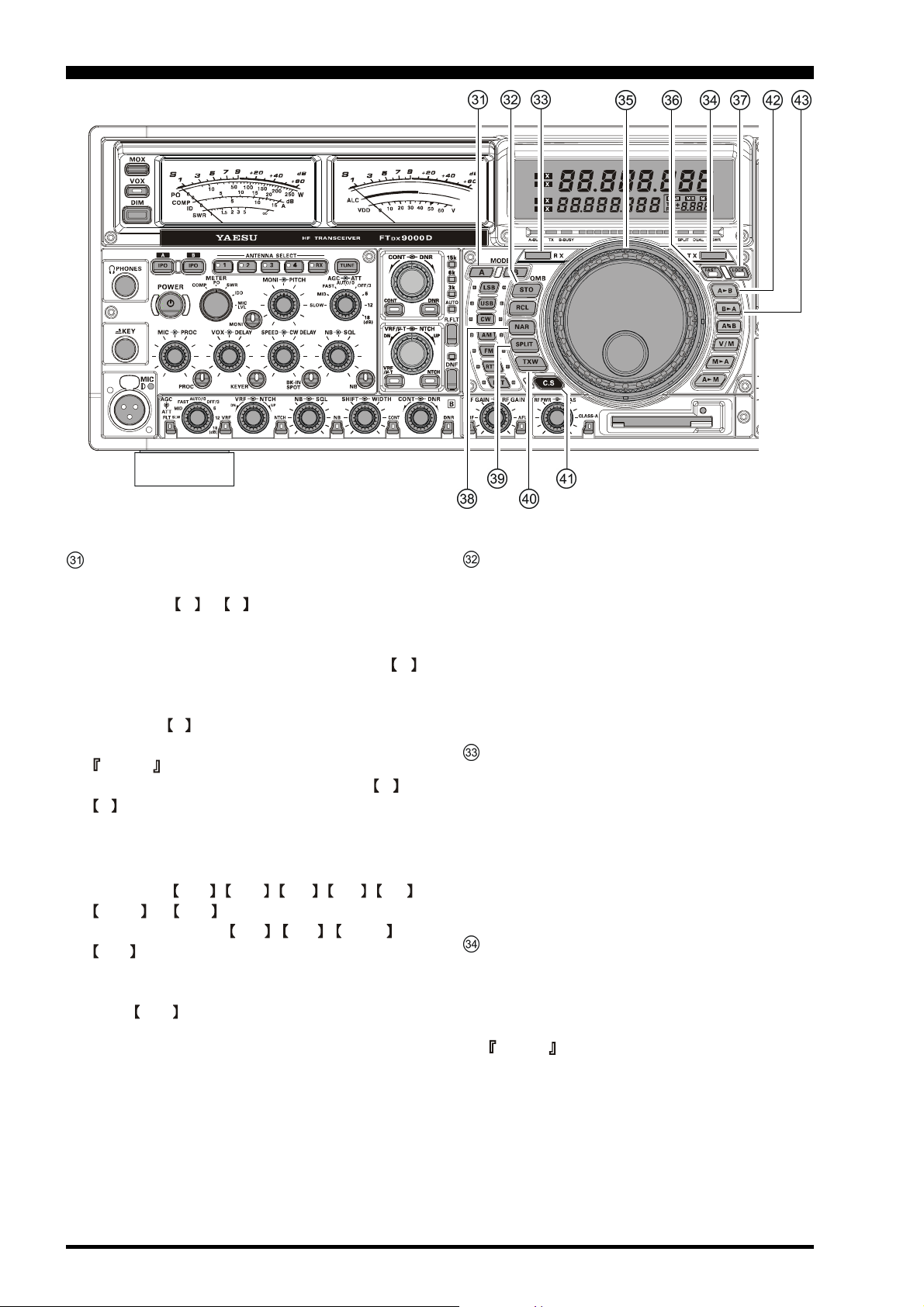
MODE Switches
A, B Button
Pressing the A or B switch will illuminate the
respective indicator imbedded within the switch, allowing adjustment of the operating mode on the Main
(VFO-A) or Sub (VFO-B) band. Pressing the A
switch causes the indicator to glow Red, signifying
Main (VFO-A) band is being adjusted. Similarly,
pressing the B switch will cause its indicator to glow
Orange, signifying Sub (VFO-B) Band adjustment.
Advice
When changing bands, be sure to press the A or
B switch first, then press the appropriate Band selector switch, so as to change operating frequencies
on the proper (Main or Sub) band.
LSB, USB, CW, AM, FM, RTTY, PKT Button
Pressing the LSB , USB , CW , AM , FM ,
RTTY , or PKT button will select the operating
mode. Pressing the CW , AM , RTTY , or
PKT button multiple times will switch between the
alternate operating features that can be used on these
modes (covered later). Also, when you press and hold
in the PKT button for one second, the user-programmed custom function setting mode will be activated.
QMB (Quick Memory Bank) Switch
STO (Store) Button
Pressing this button copies operating information (frequency, mode, bandwidth, and also repeater direction/
shift frequency and CTCSS functions on the FM mode)
into consecutive QMB Memories.
RCL (Recall) Button
Pressing this button recalls one of up to five Quick
Memory Bank memories for operation.
RX Indicator/Switch
This switch, when pressed, engages the Main (VFOA) band receiver; the indicator will glow Green when
the Main receiver is active.
When the Main (VFO-A) receiver is active, pressing
this button momentarily will mute the receiver, and
the indicator will blink. Pressing the button once more
will restore receiver operation, and the indicator will
glow Green steadily.
TX Indicator/Switch
When this button is pushed, the indicator will glow
Red, and the transmitter will be engaged on the same
frequency and mode as was set up for the Main (VFOA) band (subject to any Clarifier offset, of course).
Advice
If this indicator is not illuminated, it means that the
Sub (VFO-B) TX indicator has been selected (it will
be glowing Red). In this case, transmission will be
effected on the frequency and mode programmed for
the Sub (VFO-B) band.
Page 26 FT DX 9000D OPERATION MANUAL
Page 29
FRONT PANEL CONTROLS
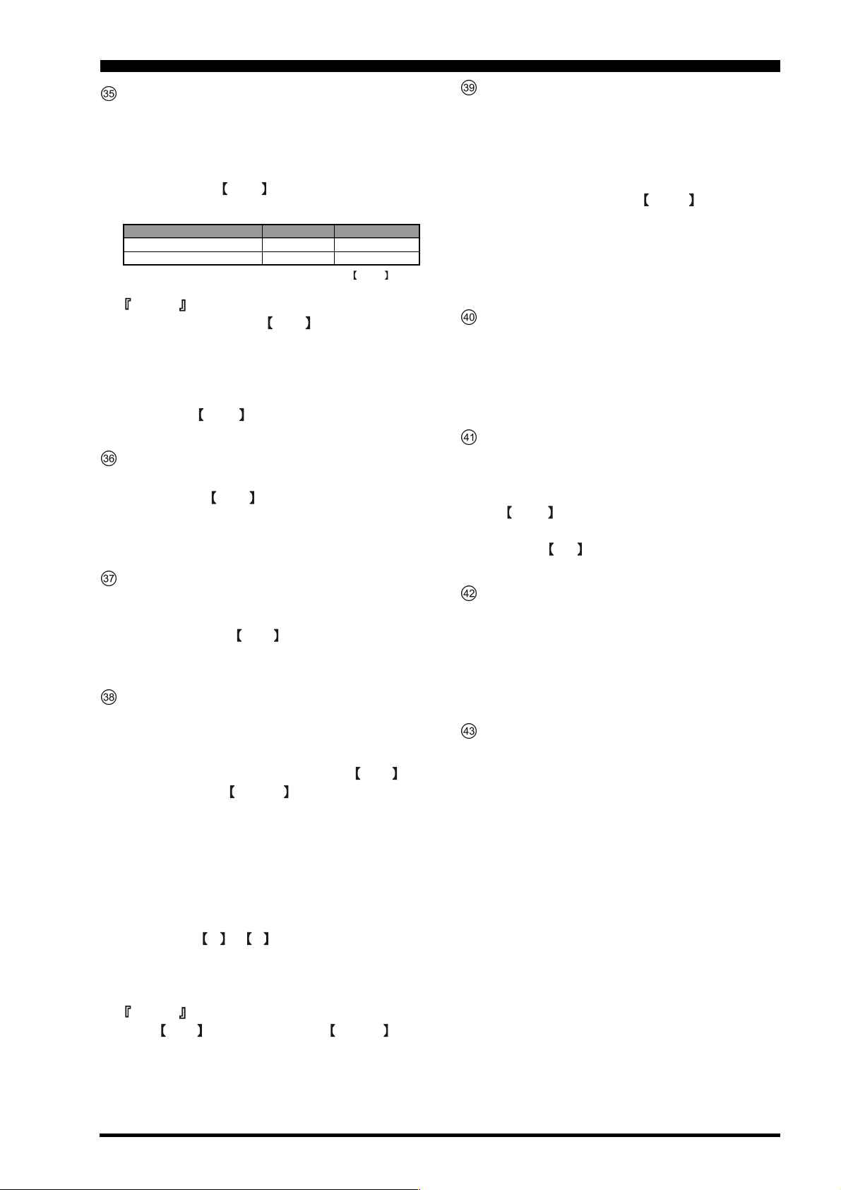
Main Dial Knob
This large knob adjusts the operating frequency of the
Main (VFO-A) Band or a recalled memory. Clockwise
rotation of this knob increases the frequency. Default
tuning increments are 10 Hz (100 Hz in AM and FM
modes); when the FAST switch is pressed, the tuning
steps increase. The available steps are:
Operating Mode 1 Step* 1 Dial Rotation
LSB/USB/CW/RTTY/PKT(LSB) 10 Hz (100 Hz) 10 kHz (100 kHz)
AM/FM/PKT(FM) 100 Hz (1 kHz) 100 kHz (1 MHz)
* Numbers in parentheses indicate steps when the FAS T switch
is On.
Advice
The tuning steps for the Main Dial (described in
this section) are set, at the factory, to 10 Hz per step.
Via Menu item “TUNING 129 MAIN DIAL STEP,”
however, you may change this setting from 10 Hz to 1
Hz instead. When 1 Hz basic steps are selected, the
action of the FAST button will be changed to 1/10
of the values listed above.
FAST Switch
Pressing this button will increase or decrease the tuning rate of the Main Tuning Knob by a factor of
ten, as mentioned in the previous section.
When this function is activated, the LED inside the
button will glow red.
LOCK Switch
This button toggles locking of the main tuning knob,
to prevent accidental frequency changes. When the
button is active, the Main Tuning Knob can still be
turned, but the frequency will not change, and the LED
inside the button will glow green.
NAR (Narrow) Switch
In the SSB/CW mode, this button is used to set the
bandwidth of the DSP IF filters to a user-programmed
bandwidth (default values are SSB: 1.8 kHz, CW/
RTTY/PSK: 300 Hz, AM: 6 kHz). When NAR has
been engaged, the WIDTH knob will be disabled.
In the AM mode, this button is used to toggle the
receiver’s bandwidth between wide (9 kHz) and narrow (6 kHz).
In the FM mode on the 28 MHz and 50 MHz bands,
this button is used to toggle the FM deviation/bandwidth between wide (± 5.0 kHz Dev./25.0 kHz BW)
and narrow (± 2.5 kHz Dev./12.5 kHz BW).
Pressing the A or B button (located above the
MODE selection buttons) will select either the main
band (VFO-A) or sub band (VFO-B) for individual
bandwidth setting.
Advice
When NAR has been engaged, the WIDTH knob
will be disabled, although IF Shift still works normally.
SPLIT Switch
Pressing this button to activates split frequency operation between the main band (VFO-A), used for transmission and sub band (VFO-B), used for reception. The
same name LED located at the right of the main tuning
knob glows orange while this function is active.
If you press and hold in the SPLIT switch for two
seconds, the “Quick Split” feature will be engaged,
whereby the Sub (VFO-B) band VFO will automatically be set to a frequency 5 kHz higher than the Main
(VFO-A) band frequency, and the transceiver will be
placed in the Split mode.
TXW “TX Watch” Switch
Pressing this key lets you monitor the transmit frequency when split frequency operation is engaged.
When receiving on the transmit frequency, the LED
indicator will glow green. Press this key again to return to normal operation.
C.S Switch
Press this button momentarily to recall a favorite Menu
Selection directly.
To program a Menu selection as the short-cut, press
the MNU key to enter the Menu, then select the
item you want to set as the short-cut. Now press and
hold in the C/S key for two seconds; this will lock
in the selected Menu item as the short-cut.
A B Switch
Press this button momentarily to transfer data from the
main band (VFO-A) frequency (or a recalled memory
channel) to the sub band (VFO-B), overwriting any previous contents in the sub band (VFO-B). Use this key to
set both main band (VFO-A) and sub band (VFO-B)
receivers to the same frequency and mode.
BA Switch
Press this button momentarily to transfer data from
the sub band (VFO-B) frequency to the main band
(VFO-A), overwriting any previous contents in the
main band (VFO-A). Use this key to set both main
band (VFO-A) and sub band (VFO-B) receivers to
the same frequency and mode.
Page 27FT DX 9000D OPERATION MANUAL
Page 30
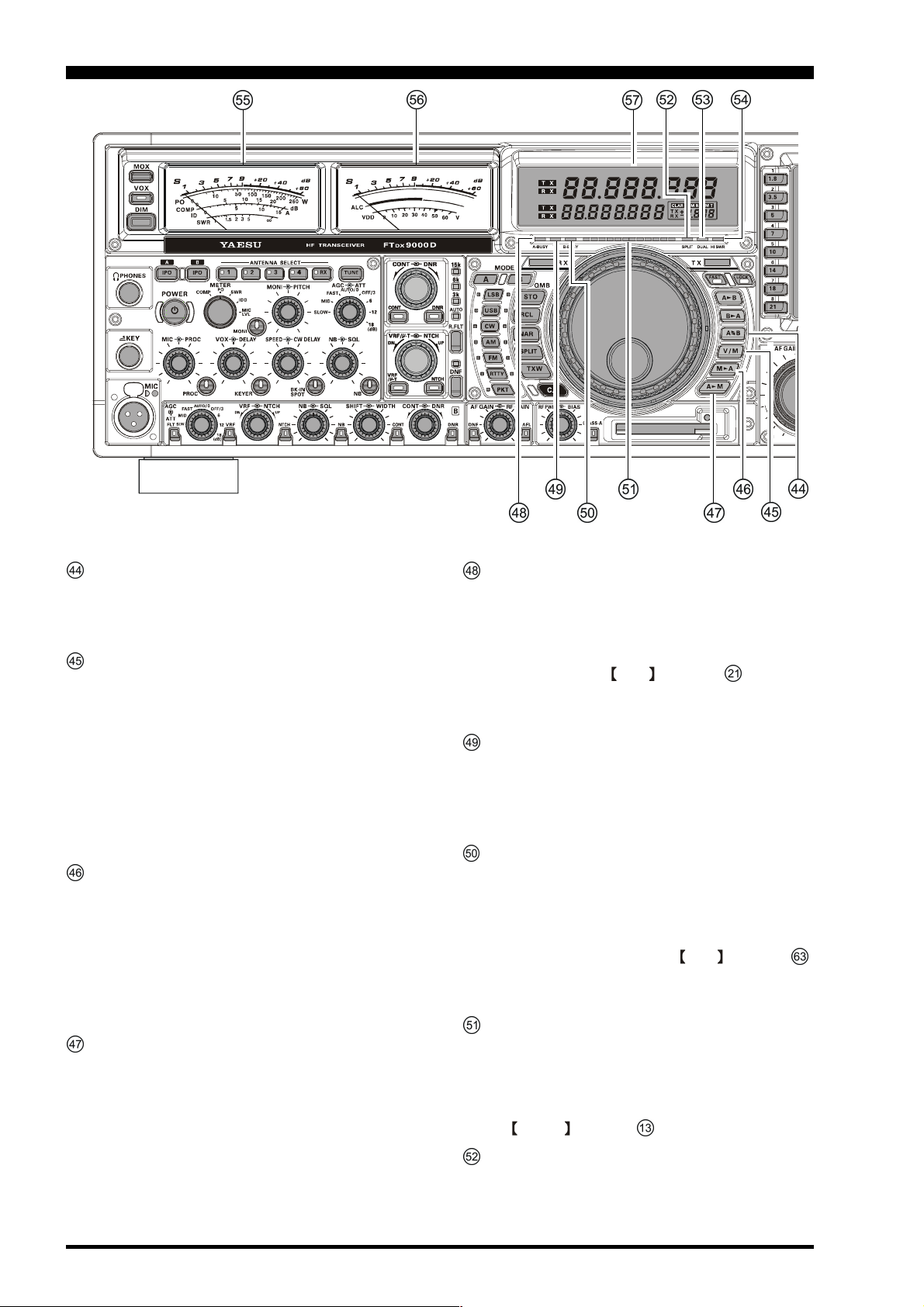
FRONT PANEL CONTROLS
A
B Switch
Pressing this button momentarily exchanges the contents of the main band (VFO-A) (or a recalled memory
channel) and the sub band (VFO-B).
V/M Switch
This button toggles main band (VFO-A) receiver operation between the memory system and the VFO.
Either “VFO,” “MEM,” or “M TUNE” will be displayed to the left of the main frequency display field
to indicate the current selection. If you have tuned off
of a Memory channel frequency (M TUNE), pressing
this button returns the display to the original memory
contents (MEM), and pressing it once more returns
operation to the Main VFO.
MA Switch
Pressing this button momentarily displays the contents
of the currently-selected memory channel for three seconds.
Holding this button in for 2 seconds copies the data
from the currently-selected memory to the Main VFO
(VFO-A), as two beeps sound. Previous data in the
Main VFO will be overwritten.
A M Switch
Pressing and holding in this key for 1/2 second (until
the double beep) copies the current operating data from
the main band (VFO-A) into the currently selected
memory channel, overwriting any previous data stored
there.
Also, pressing and holding in this button after recalling a memory, without first retuning, causes the
memory channel to be “masked,” and repeating the
process restores the masked memory.
A-BUSY Indicator
This LED glows green whenever the Main band (VFOA) receiver squelch is open. If this indicator is not
illuminated, and reception seems to have been “lost”
on the Main receiver for no apparent reason, check
the position of the SQL control (# , described
previously) and rotate it fully counter-clockwise to restore reception.
TX Indicator
This indicator glows Red during transmission.
If you attempt to transmit while operating outside of
an Amateur band, this indicator will blink Red, indicating an “out of band” condition.
B-BUSY Indicator
This LED glows green whenever the Sub band (VFOB) receiver squelch is open. If this indicator is not
illuminated, and reception seems to have been “lost”
on the Sub receiver for no apparent reason, check the
position of the SUB (VFO-B) SQL control (# ,
described later) and rotate it fully counter-clockwise
to restore reception.
Tuning Offset Indicator
This is a tuning scale that, as configured from the factory, provides a visual CW tuning indication of the
incoming signal’s offset from your transceiver's CW
carrier frequency, as programmed by the position of
the PITCH control (# , described previously).
SPLIT Indicator
This indicator glows Red when the “Split” mode is
engaged (with the Main and Sub bands operating on
different frequencies).
Page 28 FT DX 9000D OPERATION MANUAL
Page 31

FRONT PANEL CONTROLS
DUAL Indicator
This indicator glows Green when Dual Receive is engaged.
HI SWR Indicator
This indicator glows Red if the directional coupler
and microprocessor detect an abnormally high SWR
condition (over 3.0:1) that cannot be resolved by the
Automatic Antenna Tuner.
Note
If this indicator lights up, check to be sure that you
have the correct antenna selected on the current operating band. If so, you will need to check the condition
of the antenna, its coaxial cable, and/or the connectors on the cable so as to locate and correct the fault.
S-Meter (Main Receiver)
There are five functions on the main multi-meter. The
bottom five selections in the list below are transmit
functions, determined by the position of the METER
switch (# , described previously):
S: Indicates the received signal strength on
the main band (VFO-A), from S-0 to S9
+60 dB.
PO: Indicates the RF Power Output, from 0 to
250 Watts on transmit.
COMP: Indicates the compression level of the
speech processor, from 0 to 20 dB.
IC: Indicates the final amplifier drain current
(ID), from 0 to 15 A.
SWR: Indicates the antenna system observed
standing wave ratio (SWR), from 1.0 to
5.0.
MIC LVL: Indicates the relative level of modulation
from the microphone amplifier stage (affected by the setting of the MIC knob).
S-Meter (Sub Receiver)
On receive, this meter displays signal strength of incoming signals as received on the Sub (VFO-B) band
receiver.
On transmit, this meter serves as the ALC meter. The
function of this meter, on transmit, can be changed to
indication or PA Voltage (VDD) via Menu item “DISPLAY 019 RIGHT TX METER.”
ALC: Display of relative ALC voltage. On SSB, the
ALC level is chiefly controlled via the MIC
Gain control, # (described previously).
VDD: Final amplifier FET Drain Voltage (nominal
value: 50 V).
Frequency Display (See Page 37)
The upper large display field indicates the current operating frequency on the main band (VFO-A), and its
TX/RX status.
The lower small display field indicates the current operating frequency on the sub band (VFO-B), and its
TX/RX status.
Page 29FT DX 9000D OPERATION MANUAL
Page 32

FRONT PANEL CONTROLS
Advice
Sections (R.FLT) through (AF GAIN RF GAIN) below pertain to operations associated with the Sub
(VFO-B) band. Because their function is basically identical to that explained with respect to the Main (VFO-A)
band, please see the Main (VFO-A) band discussions for detailed explanations of these controls, switches, and
indicators.
R.FLT Switch
(Refer to Main (VFO-A): )
This switch allows selection of the Sub (VFO-B) band
Roofing filter.
AGC ATT Switch
(Reference: Main (VFO-A): )
AGC Switch
This switch selects the AGC characteristics for the Sub
(VFO-B) band receiver.
ATT Switch
This switch selects the degree of attenuation, if any,
to be applied to the Sub (VFO-B) receiver input.
VRF Switch
(Refer to Main (VFO-A): )
When the Sub (VFO-B) band VRF is engaged by this
switch, the VRF switch will glow orange.
Note
The µ-Tuning system is not available for use on the
Sub (VFO-B) band.
VRF NTCH Knobs
VRF Knob
This adjusts the center frequency of the Sub (VFO-B)
band VRF filter, when engaged by the VRF switch
(described in section above).
NTCH Knob
This adjusts the center frequency of the Sub (VFO-B)
band IF Notch filter, when engaged by the NTCH
switch (described in the next section).
NTCH Switch
This switch turns the Sub (VFO-B) manual IF Notch
filter On and Off. Adjustment of the center frequency
of the Notch filter is provided by the NTCH knob,
described in the previous section.
Page 30 FT DX 9000D OPERATION MANUAL
Page 33

FRONT PANEL CONTROLS
NB SQL Knobs
(Refer to Main (VFO-A): )
NB Knob
This adjusts the Sub (VFO-B) band receiver’s IF Noise
Blanker level, when the Noise Blanker is engaged via
the NB switch, described below.
SQL Knob
This knob provides adjustment of the Sub (VFO-B)
band receiver’s noise Squelch system.
NB Switch (except on FM mode)
(Refer to Main (VFO-A): )
This switch engages the Sub (VFO-B) band IF Noise
Blanker. Adjustment of the Noise Blanker level is provided by the NB knob, described in the previous
section.
SHIFT WIDTH Knobs
(except on FM mode)
(Refer to Main (VFO-A): )
SHIFT Knob
This knob adjusts the center frequency of the Sub
(VFO-B) band receiver’s DSP filter, with an adjustment range of ± 1 kHz.
WIDTH Knob
This knob varies the width of the IF DSP filter for the
Sub (VFO-B) band receiver.
CONT Switch
(Refer to Main (VFO-A): )
This is the On/Off switch for the Sub (VFO-B) band
receiver’s CONTOUR filter. When engaged, the
CONT LED will glow Orange. Adjustment of the
Sub (VFO-B) band CONTOUR filter’s frequency is
provided by the CONT knob (described in the next
section).
DNR Switch
(Refer to Main (VFO-A): )
This button turns the sub band (VFO-B) Digital Noise
Reduction circuit on and off. When the Digital Noise
Reduction is activated, the LED inside the button will
glow umber. Adjustment of the Noise Reduction level
is provided by the DNR knob, described in the next
section.
DNF Switch (Refer to Main (VFO-A): )
This switch is the On/Off switch for the Sub (VFO-B)
band receiver’s Digital Notch Filter. When turned On,
the associated LED glows Orange.
AF GAIN RF GAIN
(Refer to Main (VFO-A): )
AF GAIN Knob
This is the Sub (VFO-B) band receiver’s Volume (AF
GAIN) control.
RF GAIN Knob
This is the Sub (VFO-B) band receiver’s RF GAIN
control, which adjusts the gain of the receiver’s RF
and IF amplifier stages. This control is normally left
in the fully clockwise position.
AFL Switch
Pressing this button activates the Audio (AF) Limiter
circuit of the Sub (VFO-B) band receiver. This will
protect the audio amplifier from distortion, and protect your ears from high audio levels, caused by sudden peaks in audio input when the AGC is set to “OFF.”
When the Audio Limiter circuit is activated, the LED
inside the button will glow orange.
CONT DNR
(Refer to Main VFO-A): )
CONT (Contour)
This knob provides adjustment of the Sub (VFO-B)
band receiver’s CONTOUR filter frequency.
Advice
Use the Menu items “RX DSP 080 SUB-CONTOURLEVEL” and “RX DSP 081 SUB-CONTOURWIDTH” to configure the Sub (VFO-B) band
receiver’s CONTOUR filter.
DNR Knob
This knob is used to select one of the 16 available
noise reduction parameters for the Sub (VFO-B) band
receivers’s Digital Noise Reduction system.
Page 31FT DX 9000D OPERATION MANUAL
Page 34

FRONT PANEL CONTROLS
RF PWR BIAS Knobs
RF PWR Knob
This is the main RF Power output control for the
transceiver, active in all operating modes. Clockwise rotation increases the power output. Adjust
this control for the desired power output from the
FT DX 9000D, or for the desired system output
when using a linear amplifier or transverter.
BIAS Knob
During SSB operation, pressing the CLASS-A
button will lower the power output to a maximum
of 75 Watts, and the BIAS control will then provide adjustment of the final amplifier Bias level
between classes AB and A. Full Class-A operation provides an ultra-clean SSB wave-form. Because Class A is a high-bias, low-efficiency mode,
you should monitor the heat sink temperature (using the “SWR” page on the TFT periodically to
ensure that the operating temperature is within the
safe range, and you may adjust the Bias level more
toward the “AB” side if the heat sink gets too
warm. The power output will not change if you
adjust the setting of the BIAS control.
CLASS-A Switch
Pressing this switch engages the Class-A capability for the transmitter. The power output will be
reduced to a maximum of 75 Watts, and the Bias
level may be adjusted using the BIAS control, described in the previous section. When Class-A
operation is engaged, the Red LED inside this
switch will light up. Press this switch once more
to return to Class AB operation at a maximum
power output of 200 Watts; the Red LED will shut
off to confirm Class AB operation.
CF Card Slot
This slot accepts the supplied Compact Flash (CF) Card,
which allows storage, transfer, and recall of transceiver
configuration data and operator preferences, along with
Log Book data, etc. When the CF Card is successfully
inserted, the Red LED by the slot will light up.
To remove the card out from slot, press the small pushbutton at the right hand side of the slot.
Advice
If you get the [PLEASE CHECK A DISK] error message to
the right of the MEM CARD indication on the TFT, check
the position of the CF Card in the slot for proper alignment.
AF GAIN RF GAIN Knobs
AF GAIN Knob
Clockwise rotation of this control increases the Volume
level. Typically, you will operate with this control set past
the 9 o’clock to 10 o’clock position.
RF GAIN Knob
This is the control that adjusts the gain of the Main (VFOA) band receiver’s RF and IF stages. Clockwise rotation
increases the gain level, and this control typically is left in
the fully clockwise position, which provides maximum
receiver gain.
Using the Menu, it is possible to change the RF GAIN
control (for the Main (VFO-A) band) to serve as the Sub
(VFO-B) AF GAIN control. In this case, the Menu Item
“GENERAL 038 AF/RF DIAL SWAP” will move the
Main (VFO-A) RF GAIN control function to the knob
normally utilized for the Sub (VFO-B) receiver’s AF
GAIN control. In this way, both the Main and Sub receiver AF GAIN controls will be on the same shaft, as
will the two receivers’ RF GAIN controls.
Page 32 FT DX 9000D OPERATION MANUAL
Page 35

FRONT PANEL CONTROLS
P.BACK Switch
Press and hold in this button for 2 seconds to activate
the recording feature of the internal Digital Voice Recorder. The Voice Recorder allows you to record the
main band (VFO-A) receiver audio for the most-recent 30 seconds. While you’re recording the receiver
audio, the LED in this button glows red.
Press and hold in this button for 2 seconds once more
to stop the recording, then press this button momentarily again to play back the receiver audio for the
most-recent 30 seconds of reception before you
stopped the recording.
While playing back the receiver audio, the LED inside button will glow umber.
Press and hold in this button for 2 seconds again to
resume recording.
AFL Switch
Pressing this button activates the Audio (AF) Limiter
circuit of the Main (VFO-A) band receiver. This will
protect the audio amplifier from distortion, and protect your ears from high audio levels, caused by sudden peaks in audio input when the AGC is set to “OFF.”
When the Audio Limiter circuit is activated, the LED
inside the button will glow orange.
SHIFT WIDTH Knobs
(except on FM mode)
SHIFT Knob
This knob provides adjustment of the IF DSP passband, using 20 Hz steps for precise adjustment and
easy reduction of interference on either side of your
operating frequency. The total adjustment range is ± 1
kHz.
The normal operating setting for this knob is straight
up, in the 12 o’clock position.
WIDTH Knob
The outer WIDTH knob, when turned to the 12
o’clock position, sets the overall IF bandwidth of the
main band (VFO-A) receiver to its maximum bandwidth. Turning the WIDTH knob either direction,
reduces the overall IF bandwidth of the main band
(VFO-A) receiver.
When the NAR (Narrow) filter selection is engaged,
this control is disabled. The SHIFT control, however, is still fully functional.
Use this control to narrow the IF DSP passband, as
necessary, to reduce interference. The SHIFT control may be used to re-center the passband response
on the incoming signal, and you may find that the
CONTOUR and IF NOTCH filters may also help improve intelligibility and/or reduce interference. See
also the discussions of control # (CONT DNR)
and # (VRF/µ-T/NTCH), described previously.
Advice
When the # NAR switch has been pushed, the
WIDTH control no longer functions. The IF SHIFT
system is still fully operational, however.
ACM (
Adjacent Channel monitor
) Switch
(CW Mode)
When using a narrow bandwidth, such as 300 Hz, on
the Main (VFO-A) band receiver in the CW mode,
pressing the ACM switch will take over the Sub (VFOB) band receiver, and utilize it for monitoring the signal strength of any signals being received inside a 2.4
kHz window centered on your current operating frequency. You will not hear any of the interfering signals, but their signal strength will appear on the Sub
(VFO-B) band S-meter.
RX Indicator/Switch
This is the switch that turns the Sub (VFO-B) receiver
On and Off. When this button is pressed to make the
Sub (VFO-B) receiver active, the Green LED imbedded within the switch will light up. Pressing the switch
again will disable this receiver, and the imbedded
Green LED will turn off.
TX Indicator/Switch
This is the switch that turns the Sub (VFO-B) transmitter
On and Off. When this button is pressed to transfer transmitter control to the Sub (VFO-B) frequency and mode,
the Red LED imbedded within the switch will light up.
Pressing this switch once more will transfer frequency/
mode control back to the Main (VFO-A) side, and the
Red LED imbedded within this switch will turn off.
CLAR (Clarifier) Switch
When this switch is pushed, the CLAR/VFO-B knob
(# , described later) will be enabled for the purpose of
utilizing the CLAR/VFO-B as an “Offset tuning” control
to allow tuning away from the Main (VFO-A) frequency.
BAND/MHz Switch
BAND Switch
Pressing this button momentarily allows you to select
the main (VFO-A) operating band (Amateur bands)
using the CLAR/VFO-B knob.
MHz Switch
Pressing and holding in this button for 2 seconds allows
you to tune the main band (VFO-A) frequency down or
up in 1 MHz increments, using the CLAR/VFO-B knob.
B-DISP OFF Switch
Pressing this button causes the sub band (VFO-B) frequency to be blanked out, for local rag-chews or other
occasions when the additional display information is
not needed. When this function is activated, the LED
inside the button will glow green.
MCH/GRP Switch
MCH Switch
Pressing this button momentarily allows you to select
the memory channel using the CLAR/VFO-B knob.
GRP Switch
Pressing and holding in this button for 2 seconds allows you to select the memory group using the CLAR/
VFO-B knob.
Page 33FT DX 9000D OPERATION MANUAL
Page 36

FRONT PANEL CONTROLS
CLAR/VFO-B Knob
Depending on the status of the A/B switch (# , described later) the CLAR/VFO-B is used for functions associated
with the Main (VFO-A) or Sub (VFO-B) frequency control registers.
Advice
Functions Associated with Main (VFO-A) Control
In the case of Main (VFO-A) control, this knob is used for Clarifier tuning, as well as Up/Down selection of the Amateur band, Memory
Channels, 1 MHz tuning steps, or Memory Groups. For Main (VFO-A) control, be sure that the Orange lamp beside this control is not illuminated. If the Orange lamp is turned on, press the A/B switch (# ) to turn it off.
Clarifier Operation
When the CLAR switch (# above) is pushed, this knob may be used
to program an offset of up to ± 9.99 kHz from the Main (VFO-A) frequency. This offset is only applied, however, to the receive or transmit frequency if the FAST/RX key (# ) and/or BAND/MHz / TX key
(# ), respectively, have been pushed.
To apply the programmed frequency offset to the Receive frequency, press
the FAST/RX key (# ) momentarily. To return to the Main-VFO-A
frequency, without the offset, press the FAST/RX key once more.
To apply the programmed frequency offset to the Transmit frequency,
press the BAND/MHz / TX key (# ) momentarily. To return the
transmitter to the Main-VFO-A frequency, without the offset, press
the BAND/MHz / TX key once more.
To reset the Clarifier frequency to “0” offset, press the B-MODE/
CLEAR switch (# ).
Functions Associated with Sub (VFO-B) Operation
When the A/B switch (# ) is pressed, the Orange lamp to the right of the CLAR/VFO-B knob will light up, and this knob will now be
exercising control functions associated with the Sub (VFO-B) frequency control register. If the Orange lamp is not illuminated, please press the
A/B switch (# ). Rotation of the knob will now control the Sub (VFO-B) frequency.
Sub (VFO-B) FAST Tuning
When the FAST/RX switch (# ) is pressed, the imbedded LED
will light up, and tuning of the Sub (VFO-B) frequency will increase by a factor of 10. Press the FAST/RX button once more to
return to the normal tuning rate.
Sub (VFO-B) BAND/MHz Up/Down Control
If you press the BAND/MHz / TX switch momentarily, the imbedded LED will light up, and this knob may now be used for selection of the desired Amateur band. Pressing the BABD/MHz / TX
switch once again will cancel Up/Down Band selection, and the
LED will turn off.
If you press and hold in the BAND/MHz / TX switch for 2 seconds, the imbedded LED will light up, and this knob may now be
BAND/MHz Up/Down Control
When the BAND/MHz key (# ) is pressed momentarily, the
Red LED imbedded in the switch will light up, and you may then
use this knob for selecting the desired Amateur band. If you have
engaged the “My Bands” feature via Menu #135, this knob will
select from among just the Amateur bands that you have included in
the “My Bands” list.
If you press and hold in the BAND/MHz key (# ) for 2 seconds, the imbedded LED will glow Orange, and this knob may now
be used for rapid tuning in 1 MHz frequency steps.
Memory Channel/Memory Group Control
Pressing the MCH/GRP key (# ) momentarily will enable the
use of this knob for selection of the desired Memory Channel.
Pressing and holding in the MCH/GRP key for two seconds will
enable the use of this knob for selecting the desired Memory Group.
used for Up/Down tuning of the Sub (VFO-B) frequency in 1 MHz
steps. Press the BAND/MHz / TX switch momentarily to cancel
Up/Down tuning; the imbedded LED will turn off.
Sub (VFO-B) Mode Selection
When the B-MODE/CLEAR switch is pressed, the imbedded LED
will light up, and this knob may now be used for selection of the
operating mode for Sub (VFO-B) band operation. Pressing the BMODE/CLEAR key once more will cancel mode selection, and
the imbedded LED will turn off.
Note
Mode selection may also be accomplished by pressing the A/B key
(# ), then pressing the appropriate Mode switch (# ) to the left
of the Main tuning Dial.
Page 34 FT DX 9000D OPERATION MANUAL
Page 37

FRONT PANEL CONTROLS
FAST/RX Switch
FAST Switch
When the
ange lamp to the right of the
lights up, the CLAR/VFO-B knob (# ) will be controlling the Sub (VFO-B) frequency; pressing the
FAST/RX switch will increase the tuning rate by a
factor of 10.
RX Switch
When the CLAR switch (# ) is pressed (and its
imbedded LED is illuminated), pressing the FAST/
RX switch applies the programmed Clarifier offset
to the Main (VFO-A) receive frequency. Press the
FAST/RX switch once more to return the Main receiver to the frequency shown on the main frequency
display field; the Clarifier offset will still be present,
though, in case you want to use it again. To cancel the
Clarifier offset, press the B.MODE/CLEAR switch
(see details in # below).
A/B switch (# ) is pushed, and the Or-
CLAR/VFO-B knob
BAND/MHz / TX Switch
BAND/MHz
When the A/B switch (# ) is pressed, and the Orange lamp to the right of the CLAR/VFO-B knob
lights up, pressing the BAND/MHz switch allows
you to rotate this knob for selection of the Amateur
band to be used for the Sub (VFO-B) band.
TX Switch
When the CLAR switch (# ) is pressed (and its
imbedded LED is illuminated), pressing the BAND/
MHz / TX switch applies the programmed Clarifier
offset to the Main (VFO-A) transmit frequency. Press
the FAST/RX switch once more to return the transmitter to the Main (VFO-A) frequency shown on the
main frequency display field; the Clarifier offset will
still be present, though, in case you want to use it again.
To cancel the Clarifier offset, press the B-MODE/
CLEAR switch (see details in # below).
A/B Switch
The A/B switch controls the determines whether
the actions of the
plied to the Main (VFO-A) band (“CLAR” option),
or the Sub (VFO-B) band (“VFO-B option”).
Pressing this switch once causes the Orange lamp to
the right of the
up; in this case, rotation of the CLAR/VFO-B knob
affects operation on the Sub (VFO-B) band (tuning,
etc.). Pressing the A/B switch once more causes the
Orange lamp to turn off; in this instance, rotation of
the CLAR/VFO-B knob affects operations associated with the Main (VFO-B) band (Clarifier function,
etc.).
CLAR/VFO-B knob will be ap-
CLAR/VFO-B knob (# ) to light
[F1] ~ [F7]/DISP Keys
[F1] ~ [F7] Key
These keys are used for selection of a variety of functions, depending on the TFT operation page selected.
The actual selection available at any given time is
shown on the TFT, just above the function key.
DISP (Display) Key
This key is used for selection of the desired TFT operation page.
BAND Key
These keys allow one-touch selection of the desired
Amateur band (1.8 ~ 50 MHz).
What's more, the [0] ~ [9] keys may be used for direct
entry of a desired operating frequency during VFO
operation.
TFT Display (see page 40)
This 6.5-inch TFT display is used for viewing and
control of a variety of features, and it includes pages
including a World Map, World Clock, Spectrum
Scope, SWR and Transmitter Status, Log Book, Audio Scope and Oscilloscope, Memory Channel listing, and Menu listings, plus much more.
B.MODE/CLEAR Switch
B.MODE Switch
When the A/B switch (# ) is pressed, and the Orange lamp to the right of the CLAR/VFO-B knob
lights up, pressing the B.MODE/CLEAR switch allows you to rotate this knob for selection of the operating mode to be used on the Sub (VFO-B) band.
CLEAR Switch
When the CLAR switch (# ) is pressed (and its
imbedded LED is illuminated), pressing the
B.MODE/CLEAR switch clears out any frequency
offset you have programmed into the Clarifier register (thereby setting the offset to “Zero”).
Page 35FT DX 9000D OPERATION MANUAL
Page 38

REAR PANEL
A
ANT
Connect your main antenna(s) here, using a type-M
(PL-259) plug and coaxial feedline for each. These
antenna ports are always used for transmission, and
also are used for reception unless a separate receive
antenna is also used for the main receiver. The internal antenna tuner affects only the antenna(s) connected
here, and only during transmission. These connectors
utilize TeflonR insulation for extreme durability and
to ensure stable impedance over the entire frequency
range.
RX OUT
These BNC jacks provide output of the receiver signal lines from the Antenna jacks which are connected
to the Main (VFO-A) and sub (VFO-B) front ends.
NTENNA SWITCH
(
)
)
)
ANTENNA SWITCH
VFO-A
(
VFO-B
)
TX/RX RELAY
RX ANTENNA SWITCH
(
)
VFO-A
RX ANTENNA SWIT CH
(
)
VFO-B
Transmitter Secti on
Main (VFO-A) Receiver
Sub (VFO-B) Receiver
ANT “1”
ANT “2”
ANT “3”
ANT “4”
RX OUT
(
MAIN
BPF
RX ANT
RX OUT
(
SUB
RX ANT
This type-M jack is for a separate receive-only antenna. An antenna connected here can be used, by both
the main (VFO-A) and sub (VFO-B) receivers, when
the RX ANT button on the front panel is pressed.
If you want to use some special kind of external
bandpass filter or preamplifier, you may connect it
between the RX OUT and RX ANT jacks, as shown
in the illustration.
Main Power Switch
This is main power On (I)/Off (O) switch of the FT
DX 9000. Always turn this switch on before turning on
the front panel’s POWER button.
If this switch is not turned On, the front panel Power
switch will not function.
Turning this Main Power switch On supplies voltage
to the OCXO (Crystal Oven), ensuring that frequency
stability is always maintained even when the transceiver is turned off via the front panel's Power switch.
AC IN
Connect the supplied 3-wire AC line cord to this
socket. AC voltages of 100-240 V may be accommodated by the FT DX 9000D without any sort of modification (universal voltage input).
CIRCUIT BREAKER Switch
This circuit breaker shuts off in the event of dangerously high current consumption by the transceiver.
Advice
If the Circuit Breaker interrupts power, by all means
try to determine the cause of the over-current condition before re-applying power. To restore the Circuit
Breaker after verifying that all is normal, push this
switch in until you hear a “click.”
MIC
This 8-pin jack accepts input from a microphone utilizing a traditional YAESU HF-transceiver pinout.
REMOTE
By plugging in the supplied FH-2 Remote Control Keypad to this gold-plated jack, direct access to the FT DX
9000D CPU is provided for control functions such as
contest memory keying, plus frequency and function control. This jack may also be also used for remote control
of the VL-1000 Linear Amplifier, if used.
Page 36 FT DX 9000D OPERATION MANUAL
Page 39

REAR PANEL
+13.8V
This gold-plated output jack provides regulated, separately fused 13.8 VDC at up to 200 mA, to power an
external device such as a packet TNC. Make sure your
device does not require more current (if it does, use a
separate power source).
PTT
This gold-plated input jack may be used to provide
manual transmitter activation using a footswitch or
other switching device. Its function is identical to the
MOX button on the front panel. The same line is
available at the PACKET and RTTY jacks for TNC
control. Open-circuit voltage is +13.5 VDC, and
closed-circuit current is 5 mA.
PATCH
This gold-plated RCA input jack accepts transmitter
audio - either AFSK or voice - for transmission. This
line is mixed with the microphone audio input line, so
the microphone should be disconnected if using this
jack and mixing is not desired. The optimum impedance is 500 ~ 600 Ohms, and the nominal input level
should be 1 mV.
EXT SPKR
The EXT SPKR two-contact output jacks are gold
plated, providing audio from the Main (VFO-A) and
Sub (VFO-B) receivers for an external loudspeaker
or speakers, such as the SP-8. Inserting a plug into
one of these jacks disables the corresponding internal
loudspeaker. Impedance is 4 ~ 8 Ohms.
AF OUT
This gold-plated 3-contact jack provides dual-channel low-level receiver output, for recording or external amplification. Peak signal level is 3 Vrms at 10 kOhms. Main band (VFO-A) receiver audio is on the
left channel (tip), and sub band (VFO-B) receiver audio is on the right channel (ring). A stereo amplifier or
recorder is recommended, to record each receiver's
audio separately when dual reception is enabled (audio from either receiver, or both, may be used via this
jack). The front panel AF GAIN knobs do not affect the signals at this jack.
TRV
This gold-plated RCA jack provides a low level RF
output for use with a transverter. Maximum output is
approximately –20 dBm (0.01 mW) at 50 Ohms.
ACC
This is an accessory jack which is used at the factory
for adjustment of the radio. Please do not connect any
cable or accessory to this terminal.
TXGND
This jack’s center pin is closed to ground while the
transceiver's transmitter is engaged. It may be used
for control of a peripheral device, most typically a
linear amplifier. To enable this jack, please set Menu
item “TX GNRL 157 EXT AMP TX-GND” to the
“ENABLE” selection. This RCA connector is goldplated, and the specifications are shown below.
BAND DATA
BAND DATA1
This 7-pin output jack used for control of the VL-1000
Solid-state Linear Amplifier.
BAND DATA2
This 8-pin output jack provides band selection data
which may be used for control of optional accessories
such as the VL-1000 Solid-state Linear Amplifier.
EXT ALC
This gold-plated RCA input jack accepts negative-going external ALC (Automatic Level Control) voltage
from a linear amplifier, to prevent over-excitation by
the transceiver. Acceptable input voltage range is 0 to
-4 VDC.
ROTATOR
This 5-pin MINI-DIN Jack accepts a cable connected
to a YAESU G-800DXA/-1000DXA/-2800DXA Antenna Rotator. You may control the antenna azimuth
rotation (and rotation speed) using the Function buttons on the front panel. (Listed models are current as
of early 2005).
RTTY
This 4-pin input/output jack provides connections for
an RTTY terminal unit. Pinout is shown on page 123.
The receiver audio level at this jack is at a constant
100-mV (@600 Ohms) level. FSK keying at this jack
is accomplished by a closure of the SHIFT line to
ground by the terminal unit.
PACKET
This 5-pin input/output jack provides receiver audio
and squelch signals, and accepts transmit (AFSK) audio and PTT control, from an external Packet TNC.
Pinout is shown on page 122. The receiver audio level
at this jack is approximately 100 mV (@600 Ohms).
Page 37FT DX 9000D OPERATION MANUAL
Page 40

REAR PANEL
KEY
This 1/4-inch gold-plated phone jack accepts a CW
key or keyer paddle. A 2-contact plug cannot be used
in this jack. Key-up voltage is +5 V, and key-down
current is 1 mA. Plug wiring is shown on page 16, and
this jack may be configured for keyer, “Bug,” “straight
key,” or computer keying interface operation via Menu
item “MODE-CW 043 R-KEYER TYPE” (see page
135).
CAT
This 9-pin serial DB-9 jack allows external computer
control of the FT DX 9000D. Connect a serial cable
here and to the RS-232C COM port on your personal
computer (no external interface is required).
GND
Use this terminal to connect the transceiver to a good
earth ground, for safety and optimum performance. Use
a large diameter, short braided cable for making ground
connections, and please refer to page 13 for other notes
about proper grounding.
COM
Connect a GPS receiver capable of supplying NMEA
data (not supplied) to this jack. When you connect the
GPS receiver to this jack, the FT DX 9000D will automatically set your current location automatically into
the “World Map” page of the TFT monitor.
KEY BOARD
Connect your keyboard (not supplied) to one of these
jacks in accordance with your keyboard type (“USB”
or “PS/2”) to use the Smart Memory Card for storage
of logbook data, and for input of your location when
setting up the World Clock.
AUDIO OUT
This terminal is for future expansion of the
transceiver’s capabilities. It is designed for connection to a computer’s sound card input, but at this time
it is not supported.
AUDIO IN
This terminal is for future expansion of the
transceiver’s capabilities. It is designed for connection to a computer’s sound card output, but at this
time it is not supported.
DISPLAY
Connect an external monitor (not supplied) to this jack.
An external monitor makes TFT display information
available on a much larger screen, for ease of viewing.
USB Jack
This jack supports the USB 1.1 protocol, for connection of a USB keyboard.
Note
Other types of USB-related accessories (other than a
keyboard) are not supported by this jack, and must
not be connected here.
Page 38 FT DX 9000D OPERATION MANUAL
Page 41

FREQUENCY DISPLAY
Main (VFO-A) Band TX/RX Indicators
These combination lamp-buttons select and indicate
the transmit/receive status of the Main (VFO-A) band.
When the green “RX” lamp is lit, the receiving frequency is under control of the Main Tuning Knob
and display (either VFO-A or a recalled memory channel). When the red “TX” lamp is lit, the transmitting
frequency is under control of the Main Tuning Knob
and display. Thus, for “normal” (non-split) operation,
both the red and green lamps associated with the
Main Tuning Knob will be illuminated.
Main (VFO-A) Frequency Display
This is the Main (VFO-A) band frequency display.
Advice
When setting the CTCSS frequency for Encoding or
Tone Squelch operation, the tone information will
appear in this area during setup.
Sub (VFO-B) Band TX/RX Indicators
These combination lamp-buttons select and indicate
the transmit/receive status of the Sub (VFO-B) band.
Sub (VFO-B) Band Frequency Display
This is the Sub (VFO-B) band frequency display.
Advice
The Tone Encoder/Decoder frequency is indicated
during the setup process.
Multi-Panel
This field within the frequency display area provides
several indications, depending on the frequency control mode in use:
CLAR (Clarifier)
This window displays the Clarifier frequency offset
from the Main (VFO-A) band frequency. The Clarifier is engaged when the CLAR LED is illuminated.
MR (Memory Recall)
When the MCH/GRP switch is pushed, the currently-selected Memory channel or Memory Group
number will be displayed in this window.
MT (Memory Tune)
If you rotate the Main Tuning Dial (or change the
mode) during memory operation, the transceiver will
change into the “Memory tune” mode to indicate that
the memory contents have been temporarily changed;
“ ” lights up to confirm this change.
Repeater Shift Data
During FM operation, the Repeater Shift will be indicated in this window.
A Negative frequency shift will be indicated by “–”
while a Positive frequency shift will be indicated by
“+” in the window. During Simplex operation (no
shift), “S” will be displayed.
Page 39FT DX 9000D OPERATION MANUAL
Page 42

TFT FEATURE/CONTROL DETAILS
Pressing any of these keys provides one-touch access
to the Amateur bands from 1.8 ~ 28 MHz. When the
ENT key has been pressed first, these keys then
serve as the frequency entry digits (“1” ~ “0”) during
direct frequency entry.
Pressing this key provides one-touch access to the 50
MHz Amateur band. When the ENT key has been
pushed first, to engage direct frequency entry, pressing this key sets the decimal point after the “MHz”
portion of the frequency.
This key turns the 28 MHz low-level (0 dBm) output
from the rear-panel’s TRV jack ON or OFF. When
the Transverter function is turned on, both the TFT
and the main frequency display will show the converted frequency’s last two digits of the “MHz” field,
according to the band programmed via Menu #034
(for example, if your transverted frequency is
144.200.00 MHz, the display will show “44.200.00”
as the operating frequency.
Pressing this key selects the “General Coverage” VFO
register, for reception outside the Amateur bands.
Pressing this key momentarily engages the “direct frequency entry” mode of operation, whereby the keys
described in the (A) and (B) sections above are used
for directly programming the operating frequency.
Once the frequency has been successfully entered,
press the ENT key once more to exit to the newlyselected frequency.
For entering a frequency directly into the Sub (VFOB) register, press this key. Then use the keys described
in sections (A) and (B) above for entering the digits
of the desired frequency; when done, press the V- B
key once more to lock the newly- selected frequency
into the Sub (VFO-B) register.
This key is used for gaining access to the Menu system, for configuring various transceiver characteristics. Menu operation is described in detail, in this
manual, beginning on page 126.
Important note:
pressing this key momentarily activates the Menu, and
the Menu selections will appear on the TFT screen;
once you are finished, you must press and hold in the
MNU key for two seconds to save any configuration changes (momentarily pressing MNU to exit
will not save the changes).
These are the “Function” keys for the various functions associated with each page of the TFT’s operational capability. The exact function of each key will
depend on the page selected.
Page 40 FT DX 9000D OPERATION MANUAL
Page 43

FH-2 OPERATION
The supplied Remote Control Keypad “FH-2” can be used to control the voice memory capability for the SSB/AM/FM
modes, and the contest memory keyer for the CW mode. You can also play back up to 30 seconds of incoming received
audio, as well, for verification of a missed callsign or other purposes. Among the specific capabilities of the FH-2 are:
H Five channels of storage and playback of voice memory (20 seconds each), using your own voice for recording (see
page 92).
H Playback of the last 30 seconds of incoming receiver audio (see page 52).
H On CW, the FH-2 provides storage and recall of CW messages for repetitive CQ and contest number transmissions (see
page 106).
LOCK
OFFON
Voice Memory/CW Message Memory
Selection Keys (5 Channels)
In the case of Voice Memory, up to 20 seconds of
audio may be stored on each channel.
For CW messages and CW Text messages, up to 50
characters (“PARIS” specification) may be stored
into each channel.
Text Memory Programming Keys
These keys are used for navigation when selecting
text characters for the programming of Contest and
Text memories.
Playback Key
This key replicates the action of the P.BACK
(“Playback”) switch on the front panel of the transceiver, and is used for playing back the last 30 seconds of recorded receiver audio.
LOCK Switch
This switch may be used to lock out the FH-2’s keys, to
prevent accidental activation of FH-2 operation.
MEM Key
This key is pressed for the purpose of storing either a
Voice Memory or a Contest Keyer Memory channel’s
contents.
DEC Key
When utilizing the sequential contest number capability of the Contest Keyer, press this key to decrement
(back up) the current Contest Number by one digit (i.e.
to back up from #198 to #197, etc.).
Page 41FT DX 9000D OPERATION MANUAL
Page 44

B
ASIC
Before turning on main power, please verify the following items once more.
G Have you made all ground connections securely? See page 13 for details.
G Do you have your antenna(s) connected to the rear-panel Antenna jack(s)? See page 14 for details.
G Is your microphone (and/or key or paddle) connected? See page 15 and 16 for details.
G If using a linear amplifier, have all interconnections been successfully completed? See page 17 and 18 for details.
G Please rotate both
the transceiver turns on. See page 32 for details.
G Rotate the RF PWR control fully counter-clockwise, to set minimum power at first. See page 32 for details.
G Before attempting voice transmissions, you must be certain that the microphone you intend to use is plugged into an
“Active” microphone jack. On the front panel is a 3-pin “Cannon” (XLR) connector, and on the rear panel you’ll find
a “traditional” 8-pin round connector. At the factory, the XLR connector is selected, but you may easily change this
using the Menu item designated “MODE-SSB 069 SSB MIC SELECT;” please confirm that this Menu item is configured appropriately.
Note
If the wrong microphone jack is selected, voice transmission will not be possible.
G Once AC power is applied, please refer to the “TFT Operation Manual” and perform the setup for the Local Time. If
this setup procedure is not performed, the World Clock and Logbook functions will not operate correctly.
G If your AC mains power should suffer a significant fluctuation or interruption, we recommend that you go through a
complete power-up cycle, in order to ensure that all circuits are properly initialized. To do this, be sure the front panel
Power switch is turned off, then set the rear-panel Power switch to the “O” position. Now unplug the AC cable from the
rear panel of the transceiver, and wait ten seconds. The start-up procedure is described on the next page.
O
PERATION
AF GAIN controls to their fully counter-clockwise positions, to avoid a loud blast of audio when
: R
ECEIVING ON
A
MATEUR
B
ANDS
Page 42 FT DX 9000D OPERATION MANUAL
Page 45

B
ASIC
O
PERATION
POWER swtch
: R
ECEIVING ON
RX switch
Main (VFO-A)
AF GAIN knob
Sub (VFO-B)
AF GAIN knob
Main (VFO-A)
A
MATEUR
BAND key
BAND/MHz switch
B
ANDS
RX swtch
Sub (VFO-B)
CLAR/VFO-B knob
1. Plug the AC cable back in, set the rear-panel
Power switch to “I.”
2. Press and hold in the front-panel Power
switch for two seconds to turn the transceiver on.
3. After about 50 seconds, all circuits will
be initialized. The transceiver will start
up on 7.000.00 MHz LSB, and normal operation may
resume.
Note
To turn power off, press and hold in the front panel
POWER switch for two seconds.
Quick Note
The opening screen on the TFT will be gray, and some
text notes advising status during the boot-up sequence
may appear. When the radio is turned on for the first
time, it takes about 50 seconds (from turning the radio on to completing the self-check) until the radio
becomes ready to use; however, from the next time
you turn it on, it will take around 10 seconds until the
transceiver is ready for full operation.
4. Rotate the AF GAIN
knob (# ) to set a comfortable audio level on incoming signals or noise. Clockwise rotation of the AF
GAIN knob increases the
volume level.
Note
When using headphones, start by rotating the AF
GAIN control counter-clockwise, then bring the volume level up after you put the headphones on. This
will minimize the chance of damage to your hearing
caused by an unexpectedly-high audio level.
5. Press the MAIN RX switch (# ) to engage the
Main (VFO-A) receiver, the imbedded LED will glow
Green.
Advice
If you press the MAIN RX key (# ) when the
imbedded LED is already glowing Green, the LED
will now blink on and off; this indicates that the Main
(VFO-A) receiver is temporarily muted. Just press the
MAIN RX key once more to restore Main (VFOA) receiver operation.
Press the SUB RX switch (# ) to engage Dual
Reception (using Sub the (VFO-B) receiver in addition to the Main (VFO-A) receiver). When you press
the SUB RX key, its imbedded LED will glow green;
pressing this key once more will turn off the Sub (VFOB) receiver, and the impeded LED will glow dark. Use
the Sub Receiver’s AF GAIN knob (# ) to adjust
the Sub (VFO-B) receiver volume level.
6. Press the A switch (# ) to enable
the capability to change the operation
for the Main (VFO-A) band the imbedded LED will glow Red.
7. Surrounding the TFT are the band
selection keys; press the BAND
key corresponding to the Amateur
band on which you wish to begin operation.
Advice
H One-touch selection of each
Amateur band between 1.8 and
50 MHz is provided.
H If you press the BAND/MHz
key (# ) momentarily, the CLAR/VFO-B
knob (# ) may be used as a band selection knob.
If the CLAR/VFO-B
knob is pressed and held
in for two seconds, rotation of the BAND/
MHz key allows frequency navigation in 1
MHz steps.
H When the BAND/MHz key’s imbedded LED
is illuminated, the CLAR/VFO-B knob controls
the functions associated with the BAND/MHz
key.
Page 43FT DX 9000D OPERATION MANUAL
Page 46

B
ASIC
O
PERATION
: R
ECEIVING ON
A
MATEUR
B
ANDS
ANTENNA SELECT switch
SQL knob
PITCH knob CLAR/VFO-B knob
Advice
H Depending on the setting of the A/B switch
(# ), the function of the CLAR/VFO-B knob
(# ) will change. Please see page 34 for more
details.
H The FT DX 9000D utilizes a triple band-stack VFO
selection technique, that permits you to store up
to three favorite frequencies and modes onto each
band’s VFO register. For example, you may store
one frequency each on 14 MHz CW, RTTY, and
USB, then recall these VFOs by successive, momentary presses of the [14] MHz band key. Each
Amateur band key may similarly have up to three
frequency/mode settings applied.
8. Press one of the ANTENNA SELECT (1~4)
switches to select the appropriate antenna for the band
in use; alternatively, if one is connected, you may also
press the RX antenna selection switch. Up to four
TX/RX antennas may be connected, or one RX-only
antenna.
Advice
Once you have made your antenna selection, that antenna is “remembered” by the microprocessor in conjunction with the VFO register (frequency and mode)
in use when you chose that particular antenna.
MODE key
FAST switch
MAIN tuning dial
9. Press the appropriate MODE key
(# ) to select the desired operating mode.
Advice
H By convention in the Amateur
bands, LSB is used on the 7
MHz and lower bands (with the
exception of 60 meters), while
USB is utilized on the 14 MHz
and higher bands.
H When changing modes from SSB to CW, you will
observe a frequency shift on the display. This shift
represents the BFO offset between the “zero beat”
frequency and the audible CW pitch (tone) you
can hear (the pitch is programmed by the
PITCH control), even though the actual tone
that you hear is not changing. If you do not want
this frequency shift to appear when changing
modes from (for example) USB to CW, use the
Menu item “MODE-CW 050 CW FREQ DISPLAY,” described on page 136.
H When operating on the FM mode, rotate the
SQL (Squelch) control (# ) clockwise just
to the point where the background noise is just
silenced. This is the point of maximum sensitivity to weak signals. Excessive advancement of the
SQL control will degrade the ability of the receiver to detect weak signals. Adjustment of the
Sub (VFO-B) band Squelch is accomplished using the Sub SQL control (# ); see page 31.
Page 44 FT DX 9000D OPERATION MANUAL
Page 47

B
ASIC
O
PERATION
: R
ECEIVING ON
A
MATEUR
B
ANDS
10. Rotate the Main Tuning Dial knob to tune around
the band, and begin normal operation.
Quick Note
H Clockwise rotation of the Main tuning Dial in-
creases the operating frequency, one “step” of the
synthesizer at a time; similarly, counter-clockwise
rotation of the Main tuning Dial will decrease
the frequency.
Two steps, one “normal” and one “fast,” are available on each operating mode. Pressing the
FAST key engages the “Fast” tuning selection.
Operating Mode 1 Step 1 Dial Rotation
LSB, USB, CW, RTTY, 10 Hz [100 Hz] 10 kHz [100 kHz]
PKT(LSB)
AM, FM, PKT(FM) 100 Hz [1 kHz] 100 kHz [1 MHz]
[ ]: FAST switch set to “ON”
OPERATION ON 60-METER (5 MHZ) BAND (U.S. VERSION ONLY
The FT DX 9000D includes the capability for transmission and reception on the five spot frequencies assigned to the
Amateur Service in the United States. To operate on the 5 MHz band:
H It is possible to separate the frequency change over
one dial rotation, while operating solely on the
CW mode, using the Menu items “TUNING 129
MAIN DIAL STEP,” and “TUNING 130 MAIN
DIAL CW FINE” See page 144.
H If you want to navigate quickly, so as to effect
rapid frequency change, there are several techniques available:
o Direct keyboard frequency entry of the fre-
quency (see page 57).
o Use the CLAR/VFO-B knob to tune in 1
MHz steps (see page 57).
o Use the microphone’s Up/Down scanning keys,
if your microphone is so equipped.
)
1. Press the V/M key (# ) once to enter the
“Memory” mode (a memory channel number “USX”
will appear on the display in the Multi-Panel on the
TFT display.
2. Memory channels “US1” through “US5” are pre-programmed, at the factory, with the permitted frequencies in the 5 MHz band, and the USB mode is automatically selected on these channels.
3. To exit from 60-meter operation and return to the VFO
mode, just press the V/M key.
Note
The frequencies and operating mode for 5 MHz band operation are both fixed, and may not be changed.
V/M key
Page 45FT DX 9000D OPERATION MANUAL
Page 48

B
ASIC
O
PERATION
: R
ECEIVING ON
A
MATEUR
B
ANDS
CLAR (CLARIFIER) OPERATION ON MAIN (VFO-A
The CLAR button and CLAR/VFO-B knob are used to offset either the receive, transmit, or both frequencies from
their settings on the main band (VFO-A) frequency (the Clarifier does not affect the sub band (VFO-B), however). The four
small numbers on the Multi Display Window show the current Clarifier offset. The Clarifier controls on the FT DX 9000 are
designed to allow you to preset an offset (up to ± 9.999 kHz) without actually retuning, and then to activate it via the
Clarifier’s RX (FAST RX) and TX (BAND/MHz TX) buttons. This feature is ideal for following a drifting station, or for
setting small frequency offsets sometimes utilized in DX “Split” work.
Here is the technique for utilizing the Clarifier:
1. Press the CLAR switch (# ). The LED imbedded
in the switch will glow Red to signify that rotation of
the CLAR/VFO-B knob (# ) will allow setting of
a frequency offset.
2. Press the FAST/RX switch (# ). On the display,
“CLAR” and “RX” will appear, and the programmed
offset will be applied to the receive frequency.
3. Rotation of the CLAR/VFO-B knob will allow you
to modify your initial offset on the fly. Offsets of up to
± 9.99 kHz may be set using the Clarifier.
To cancel the application of the offset to the receiver frequency temporarily, press the FAST/RX switch. The
“CLAR RX” notation will disappear from the display.
)
RX key
CLAR/VFO-B knob
CLAR key
CLEAR key
To cancel Clarifier operation, press the CLAR switch.
Advice
Turning the Clarifier Off simply cancels the application of
the programmed offset from the receive and/or transmit
frequencies. To clear out the programmed Clarifier offset
altogether, and reset it to “zero,” press the CLAR switch
(# ). The programmed offset is displayed in the small
multi-channel window of the frequency display.
Note
If the Clarifier seems not to be operating, check to see if
the Orange lamp to the right of the CLAR/VFO-B knob
(# ) is illuminated. If so, pressing the A/B switch
(# ) will cause the Orange lamp to the right of the
CLAR/VFO-B knob to go out. Now press the CLAR
switch (# ) to begin Clarifier operation.
The LED Bar Display provides a graphical representation of the Clarifier offset.
On CW, the Bar Display field is used for CW Center Tuning, instead of Clarifier Offset, as the transceiver is configured at the factory. If you wish to change this, so that the Clarifier Offset is also displayed on CW, use the following
procedure:
Without changing the receive frequency, you may
alternatively apply the Clarifier offset to the transmit frequency (typically, for “split” DX pile-ups).
See page 95 for details.
TXCLAR
1. Press the MNU key (# ) to enter the Menu
mode.
2. Rotate the Main Tuning Dial to select Menu item
“DISPLAY 016 BAR DISPLAY SELECT.”
3. Rotate the CLAR/VFO-B knob (# ) to select
“CLAR” (replacing the default “CW-TUNE” selection).
4. Press and hold in the MNU key for two seconds to
save the new setting and exit to normal operation.
(TX frequency < RX frequency)
(TX frequency = RX frequency)
(TX frequency > RX frequency)
Page 46 FT DX 9000D OPERATION MANUAL
Page 49

B
ASIC
O
PERATION
: R
ECEIVING ON
A
MATEUR
B
ANDS
LOCK
You may lock the setting of the Main Tuning Dial, to prevent accidental frequency change.
To lock out the Main Tuning Dial (# ), just press the
LOCK switch (# ) that is located to the right of the
Dial. To unlock the Dial setting, and restore normal tuning, just press the LOCK switch once more.
LOCK switch
DIM
The illumination level of the analog meters, main frequency display, and the TFT may be reduced, if you are using the
transceiver in a dark environment where high brightness is not desired.
To reduce the illumination level, press the DIM switch
(# ), located to the left of the leftmost analog meter. To
restore full brightness, press the DIM switch once more.
You may also customize the amount of brightness reduction engaged by the pressing of the DIM switch, and
may use different brightness levels for different front panel
areas. Menu item “DISPLAY 14 DIMMER-METER” adjusts the brightness level of the analog meters, while menu
item “DISPLAY 15 DIMMER-VFD” sets the brightness
levels of the main frequency display and the TFT (these
settings are effective only when the DIM switch is
pressed).
DIM switch
B-DISP OFF
During monoband operation, you may wish to disable (temporarily) the display of the Sub (VFO-B) band frequency.
To do this, press the B.DISP OFF switch (# ), found
at the lower left side of the CLAR/VFO-B knob (# ).
Press the B.DISP OFF switch once more to restore the
Sub (VFO-B) band frequency display.
B-DISP OFF switch
Page 47FT DX 9000D OPERATION MANUAL
Page 50

CONVENIENT FEATURES
DUAL RECEIVE
The FT DX 9000D is capable of simultaneous reception, using the Main (VFO-A) and Sub (VFO-B) receivers, in what is
called the Dual Receive mode. Especially useful for DX work, here is the operating procedure for Dual Receive operation.
1. While receiving on the Main (VFO-A) band, engage
the Sub (VFO-B) receiver by pressing the SUB RX
key (# ). You will now be receiving on the two frequencies shown on the main frequency display.
2. Adjusting the volume:
To adjust the Main (VFO-A) audio level, rotate the
Main AF GAIN control (# ). To adjust the Sub
(VFO-B) audio level, rotate the Sub AF GAIN control (# ). In both cases, clockwise rotation of the
knob will increase the volume level.
3. Press the B switch (# ) to enable the capability to
change the operating mode for the Sub (VFO-B) band.
4. Having pressed the B key in the previous step, you
may also press the BAND keys surrounding the TFT
to select the operating band on which you want to set
up the Sub (VFO-B) receiver.
5. After you have set up the band and mode for the Sub
(VFO-B) band, you should now select the proper antenna, using the ANTENNA SELECT 1 ~ 4 switches
(# ), or, for receive-only capability, the RX (Antenna) switch (# ).
6. Rotate the MAIN tuning dial (# ) to adjust the
Main (VFO-A) frequency, and rotate the CLAR/
VFO-B tuning dial (# ) to adjust the Sub (VFOB) frequency.
7. To cancel Dual Receive operation, and receive just
on the Main (VFO-A) receiver, press the RX switch
(# ); the Orange LED to the right of the CLAR/
VFO-B knob will go out, and monoband operation
on the Main (VFO-A) receiver will resume.
Note
Please remember that, so long as the B Mode switch
(# ) is illuminated, any mode or band changes will still
be applied to the Sub (VFO-B) band, whether or not Dual
Receive is engaged.
Quick Note
By convention in the Amateur bands, LSB is used on the 7
MHz and lower bands (with the exception of 60 meters),
while USB is utilized on the 14 MHz and higher bands.
MAIN(VFO-A)
SQL knob
MAIN(VFO-B)
SQL knob
MODE
B key
MODE key
MAIN(VFO-A)
MAIN tuning dial
SUB(VFO-B)
AF GAIN knob
MAIN(VFO-A)
AF GAIN knob
BAND key
SUB(VFO-B)
RX key
Advice
H When operating in Dual Receive, the manner in which
the audio is fed to the left and right sides of your headphones (Stereo, Monaural, or Mixed) may be configured using Menu item “RX AUDIO 076 HEADPHONE MIX” (see page 139).
H When changing modes from SSB to CW, you will ob-
serve a frequency shift on the display. This shift represents the BFO offset between the “zero beat” frequency and the audible CW pitch (tone) you can hear
(the pitch is programmed by the PITCH control:
# ), even though the actual tone that you hear is not
changing. If you do not want this frequency shift to
appear when changing modes from (for example) USB
to CW, use the Menu item “MODE-CW 050 CW
FREQ DISPLAY,” described on page 136.
H When operating on the FM mode on the Sub (VFO-
B) band, rotate the Sub (VFO-B) SQL (Squelch)
control (# ) clockwise just to the point where the
background noise is just silenced. This is the point of
maximum sensitivity to weak signals. Excessive advancement of the SQL control will degrade the ability of the receiver to detect weak signals. Adjustment
of the Main (VFO-A) band Squelch is accomplished
using the Main SQL control (# ).
Page 48 FT DX 9000D OPERATION MANUAL
Page 51

CONVENIENT FEATURES
DUAL RECEIVE: FULL DUPLEX OPERATION
The FT DX 9000D includes a unique capability among HF
transceivers: the ability to operate in a full duplex environment, where by you can transmit on the Main (VFOA) band while simultaneously tuning around, on a different band, on the Sub (VFO-B) band. This affords the contest operator extra tuning time in search of new contacts
and multipliers while calling CQ on the “run” band. This
yields “SO2R” (Single Operator, Two Radio) operating
capability while using only one transceiver!
To engage Full Duplex crossband operation, set Menu item
“TX GNRL 158 FULL DUP” to “DUP” instead of the
default “SIMP” selection. To return to normal (non-duplex) operation, return Menu to SIMP.
When Full duplex operation is engaged, you may receive
on the Sub (VFO-B) band frequency while transmitting,
during dual receive operation, on a different band on the
Main (VFO-A) band. This allows you to tune for contacts
on 15 meters, for example, while calling CQ on 20 meters
during a slow time in a contest. Press the Sub (VFO-B)
band TX Button/LED (# ) to switch transmit control
to that VFO to call a station, then press the Main (VFO-A)
band TX Button/LED (# ) to return to the “run” band
and continue your “CQ” process.
Note
Full Duplex operation within the same band (e.g. both Main
and Sub VFOs on 20 meters) is not possible.
Important Guidelines for Full Duplex Operation
Remember that, at your station location, the capability
exists for damaging RF voltage to be conducted from your
transmitting antenna into your receiving antenna during
full duplex operation. The exact amplitude will depend on
the operating frequency, proximity and polarization alignment of the antennas, and the transmitting power level (including your linear amplifier, if used).
Accordingly, you should take some time, in assembling
your station, to ensure that proper isolation exists between
your station antenna systems. One way to do this is to connect the “receive” antenna coaxial cable to the “Transmitter” jack of low-power Wattmeter, and connect the “Antenna” jack of the Wattmeter to a 50-Ohm Dummy load.
Now transmit on the “TX” antenna you will be using, and
observe the deflection (if any) on the low-power Wattmeter connected to the “receive” antenna. For safe operation
of the FT DX 9000D, you should observe “10 mW” or less
on the Wattmeter.
This capability within a single transceiver is a unique feature of the FT DX 9000D. It relieves you of the need to run
separate key, PTT, and other control lines to two different
radios from your logging computer.
Page 49FT DX 9000D OPERATION MANUAL
Page 52

CONVENIENT FEATURES
DUAL RECEIVE: FULL DUPLEX OPERATION
Using Headphones for Dual Receive
To take advantage of dual reception, you will want to connect stereo headphones to the PHONES jack. Like the AF GAIN
control, headphone audio mixing can also be configured as desired from Menu Selection “RX AUDIO 076 HEADPHONE
MIX.” Three audio mixing schemes are selectable as follows:
OFF: Audio from the Main band (VFO-A) receiver is heard only in the left ear, and Sub band (VFO-B) receiver audio
solely in the right ear.
MID: Audio from both Main (VFO-A) and Sub (VFO-B) band receivers can be heard in both ears, but Sub band (VFO-
B) audio is attenuated in the left ear and Main band (VFO-A) audio is attenuated in the right ear.
FULL: Audio from both Main (VFO-A) and Sub (VFO-B) band receivers is combined and heard equally in both ears
“Monaural” mode).
Sideband Diversity Reception
Here you receive a single AM signal through the two receivers, each receiving the opposite sideband. Skywave-propagated
signals often show phase distortion in this mode, but it gives you a view of the entire passband, from which you can then
select the best sideband for listening (or for SWL Dx’ing, you may want to listen to both sidebands at the same time, to get
the best copy). On groundwave signals, where the phase of the sidebands is likely to be the same, there is an interesting
sense of depth to the signal.
To tune in a signal using this mode, you should have stereo headphones connected to the front panel PHONES jack or an
external stereo speaker connected to the rear panel EXT SP jacks.
Ì Set the main band (VFO-A) to either LSB or USB
mode, and tune for zero beat on the desired signal.
Ì Press the AB button (# ) to copy this mode and
frequency into the sub band (VFO-B), then press the
mode button to select the opposite sideband for the
main band (VFO-A).
Ì If using headphones, set the headphone mixing scheme
to the “COMBINE-1” mode via the Menu Selection
76: Head Phone Mix , and activate dual reception.
Ì Adjust the AF GAIN knob(s) to balance the vol-
ume of the two receivers.
If interference is present on one of the channels, you may
have to turn its AF GAIN control to suppress that channel
(or press the green “RX” LED/button to disable the receiver with the sideband experiencing interference). Otherwise, try changing the headphone audio mixing scheme
to “FULL” or “OFF” in the Menu Selection “RX AUDIO
076 HEADPHONE MIX” for different effects (or try settings with similar effects on your external amplifier). Although you don’t get the “stereophonic” effect in the monaural mode, the two signals are still mixed, offering the
potential for much better copy than in regular AM or even
single-sideband ECSS modes.
switch
Sub (VFO-B)
switch
switch
Main (VFO-A)
Page 50 FT DX 9000D OPERATION MANUAL
Page 53

CONVENIENT FEATURES
DUAL RECEIVE: FULL DUPLEX OPERATION
Bandwidth Diversity Reception
This mode involves receiving the same signal through two different bandpass filters. The frequency and mode of both the
Main band (VFO-A) and Sub band (VFO-B) are the same. The main band (VFO-A) can be set up for a narrow bandpass,
and the Sub band (VFO-B) for a wide bandpass, using the WIDTH knobs, resulting in a spatial perception of the channel.
Although any mode (except FM) can be used, CW offers the widest array of choices, and perhaps the most startling effects
on crowded channels.
Stereo headphones or an external stereo speaker are recommended for this mode. To set up the transceiver for bandwidth
diversity reception:
Ì Select the desired mode on the Main band (VFO-A).
Ì Tune to the signal of interest.
Ì Press the AM button (# ) to copy this mode
and frequency into the Sub band (VFO-B).
Ì If using headphones, set the headphone mixing scheme
to the “MID” mode via the Menu Selection “RX AUDIO 076 HEADPHONE MIX” and activate dual reception.
Ì Adjust the AF GAIN knob(s) (# and ) to bal-
ance the volume of the two receivers.
Ì Now try manipulating the SHIFT and WIDTH
controls (on both main band (VFO-A) (# ) and sub
band (VFO-B) (# ) receivers) to observe the interesting effects of bandwidth diversity.
switch
Sub (VFO-B)
switch
switch
Main (VFO-A)
Polarity Diversity
Similar in concept to the bandwidth diversity capability just described, another interesting capability of the FTDX9000
is the ability to use two different antennas on the same frequency, using dual reception. For example, you might have
a horizontal Yagi on the main band, and a vertical antenna on the sub band, then lock the two frequencies together and
engage dual reception.
Frequently, the fading observed on the HF bands is not so much a change in ionization level, but rather a shift in the
polarization of the signal as it travels to and from the ionosphere. Having an opposite-polarization antenna available
can fill in the signal during deep fades, and you may then transmit on whichever antenna is providing the strongest
signal at the moment (see the discussion below on Split Frequency operation).
Page 51FT DX 9000D OPERATION MANUAL
Page 54

CONVENIENT FEATURES
)
P.BACK (AUDIO PLAYBACK
Once engaged by the operator, the FT DX 9000D begins the automatic recording of the last 30 seconds of incoming receiver
audio on the Main (VFO-A) band. This capability is especially useful for confirming a callsign that may have been difficult
to copy due to noise or QRM, etc.
Recording
Press and hold in the P.BACK key (# ) for two seconds to initiate recording; an LED imbedded in the switch
will light up to confirm that recording is in progress. The
recorder will store up to 15 seconds of the Main (VFO-A)
band received audio, and will retain the most-recent 30
seconds of audio on a running basis.
Pressing the P.BACK switch once more will halt the recording, and the LED imbedded in the switch will go out.
Note
When the transceiver is turned off, the contents of the recording memory are erased!
Playback
Press the P.BACK key (# ) momentarily, after recording has been halted, to begin playback of the recorded
audio. The last 15 seconds of audio will be heard in the
speaker or headphones. If you do not intervene, the entire
15 seconds will be played back repeatedly by pressing the
P.BACK key momentarily again. The next time you press
the P.BACK key, it will pick up the playback where you
left off.
FROM MAIN
(
VFO-A) RECEIVER
P.BACK knob
Stop
Start
15 Seconds
The P/B key of the supplied FH-2 Keypad can also serve as a remote-control recording/playback switch. Operation
is described below.
Recording
Press and hold in the FH-2’s P/B key for two seconds to initiate recording.
The front panel P.BACK switch’s LED will light up
to confirm that recording is in progress.
Press the FH-2’s P/B key momentarily to halt recording; the front panel’s LED will go out.
You may also press the front panel’s P.BACK key
(momentarily) to halt recording, as well.
When the transceiver is turned off, the contents of the
recording memory are erased.
Playback
Press the FH-2’s P/B key momentarily, after recording has been halted, to begin playback of the recorded
audio. The last 15 seconds of audio will be heard in the
speaker or headphones. If you do not intervene, the
entire 15 seconds will be played back, after which the
playback will stop automatically. To halt playback at
any time, just press the P/B key momentarily again.
The next time you press the P.BACK key, it will pick
up the playback where you left off. You may also press
the front panel’s P.BACK key (momentarily) to play
back the recorded audio, as well.
LOCK
OFFON
Page 52 FT DX 9000D OPERATION MANUAL
Page 55

CONVENIENT FEATURES
“MY BANDS” OPERA TION
When operating on an Amateur Band on the Main (VFO-A) register, it is possible to use the BAND/MHz switch (# )
to engage the use of the CLAR/VFO-B knob (# ) for Amateur band selection. The “My Bands” feature allows you to
select several Amateur bands, and make only those bands available for selection via the CLAR/VFO-B tuning knob.
This feature can be very useful in a contest, where the 10/18/24 MHz band are not used, or if you do not have antennas for
some bands.
“My Bands” Setup
1. Press the MNU key (# ) to engage the Menu
mode; the Menu list will appear on the TFT.
2. Rotate the Main Tuning Dial (# ) to select Menu
item “TUNING 135 MY BAND”.
3. Rotate the CLAR/VFO-B knob (# ) to choose a
band that you wish to skip (omit) from the band-selection loop (when using the CLAR/VFO-B knob
for band selection). The available choices are 1.8/3.5/
7/10/14/18/21/24/28/50/GEN/TRV, and the factorydefault selection is TRV (only).
4. Press the ENT key (# ) to set the omission command to ON.
5. Repeat steps 3 and 4 to select/deselect as many bands
as you like.
MAIN tuning dial knob
ENT key
MNU key
CLAR/VFO-B knob
Note
The “ON” command sets the selected band to be skipped, while
the “OFF” command sets the selected band to be included in
the band-selection list.
6. Press and hold in the MNU key for two seconds to
lock in the new configuration and exit to normal operation.
“My Bands” Operation
1. Press the BAND/MHz switch (# ); the imbedded LED will glow Red.
2. Rotate the CLAR/VFO-B knob (# ) to choose the
Amateur band on which you wish to operate. Only
those Amateur bands that have not been skipped will
appear as you scroll through the bands.
1.8MHz
MHz
3.5
MHz
7
MHz
10
14
18
21
24
28
50
MHz
MHz
MHz
MHz
MHz
MHz
MHz
TRV
GEN
3.5
14
21
28
7
MHz
MHz
MHz
MHz
«
3.5MHz
7MHz
14MHz
BAND/MHz knob
CLAR/VFO-B knob
21MHz
28MHz
Page 53FT DX 9000D OPERATION MANUAL
Page 56

CONVENIENT FEATURES
BAND ST ACK OPERATION
The FT DX 9000D utilizes a triple band-stack VFO selection technique, that permits you to store up to three favorite
frequencies and modes onto each band's VFO register. For example, you may store one frequency each on 14 MHz CW,
RTTY, and USB, then recall these VFOs by successive, momentary presses of the [14] MHz band key. Each Amateur band
key may similarly have up to three frequency/mode settings applied. Both the Main (VFO-A) and Sub (VFO-B) systems
have their own, independent, band stacks.
A typical setup, for the 14 MHz band, might be arranged
like this:
1. Program 14.0250 MHz, CW Mode,
then press the [14] MHz BAND
key (# );
2. Program 14.080 MHz, RTTY Mode,
then press the [14] MHz BAND
key;
3. Program 14.195 MHz, SSB Mode,
then press the [14] MHz BAND
key.
With this configuration, successive momentary presses of
the [14] MHz BAND key will allow you to toggle sequentially through these three VFOs.
Band Stack1
BAND
Key
Frequency (MHz) MODE
1.800000 CW
1.8
3.500000 LSB
3.5
5.000000 USB
5
7.000000 LSB
7
10.100000 CW
10
14.100000 USB
14
18.068000 USB
18
21.000000 USB
21
24.890000 USB
24
28.000000 USB
28
50.000000 USB
50
15.000000 USB
GEN
Band Stack2
Frequency (MHz) MODE
1.800000 CW
3.500000 LSB
5.000000 USB
7.000000 LSB
10.100000 CW
14.100000 USB
18.068000 USB
21.000000 USB
24.890000 USB
28.000000 USB
50.000000 USB
15.000000 USB
Band Stack3
Frequency (MHz) MODE
1.800000 CW
3.500000 LSB
5.000000 USB
7.000000 LSB
10.100000 CW
14.100000 USB
18.068000 USB
21.000000 USB
24.890000 USB
28.000000 USB
50.000000 USB
15.000000 USB
Page 54 FT DX 9000D OPERATION MANUAL
Page 57

CONVENIENT FEATURES
DIAL SWAP CONFIGURATION (AF/RF GAIN CONTROLS
Using the Menu, it is possible to change the RF GAIN control (for the Main (VFO-A) band) to serve as the Sub (VFOB) AF GAIN control. In this case, the Menu Item “GENERAL 038 AF/RF DIAL SWAP” will move the Main (VFO-A)
RF GAIN control function to the knob normally utilized for the Sub (VFO-B) receiver’s AF GAIN control. In this
way, both the Main and Sub receiver AF GAIN controls will be on the same shaft, as will the two receivers’ RF GAIN
controls, and this may be particularly useful during Dual Receive operation.
MAIN (VFO-A)
RF GAIN knob
SUB (VFO-B)
RF GAIN knob
MAIN (VFO-A)
AF GAIN knob
SUB (VFO-B)
)
AF GAIN knob
Dial Swap Setup
1. Press the MNU key (# ) to engage the Menu
mode; the Menu list will appear on the TFT.
2. Rotate the Main Tuning Dial (# ) to select Menu
item “GENERAL 038 AF/RF DIAL SWAP.”
3. Rotate the CLAR/VFO-B knob (# ) so as to se-
lect “SWAP” instead of the factory-default “NORMAL” selection.
4. Press and hold in the MNU key for two seconds to
save the new configuration and exit to normal operation.
Quick Point
If the Dial Swap function has been engaged, the Main
(VFO-A) AF GAIN RF GAIN control (# ) will be
reconfigured so that it now operates as AF GAIN
(MAIN) AF GAIN (SUB); the Sub (VFO-B) band’s
AF GAIN RF GAIN control (# ) will now be con-
figured as RF GAIN (MAIN) RF GAIN (SUB).
MNU key
Main tuning dial knob
CLAR/VFO-B knob
Page 55FT DX 9000D OPERATION MANUAL
Page 58

CONVENIENT FEATURES
C.S (CUSTOM SWITCH
An often-used Menu mode selection may be brought out to the front panel’s C.S key
C.S Setup
1. Press the MNU key (# ) to engage the Menu
mode; the Menu list will appear on the TFT.
2. Rotate the Main tuning dial to select the Menu item
you want to be able to access via the C.S key (# ).
3. Press and hold in the C.S key for two seconds to
lock in your selection.
4. Press and hold in the MNU key for two seconds to
save the new configuration and exit to normal operation.
Menu Selection Recall via [C.S] Switch
Press the C.S switch (# ).
On the TFT, the programmed Menu item will appear. You
may now rotate the CLAR/VFO-B knob (# ) to change
the setting of this menu item. Press the MNU key (# )
for two seconds, when you are done, to save the new configuration and exit to normal operation.
)
C.S key
Main tuning dial
C.S key
MNU key
CLAR/VFO-B knob
Page 56 FT DX 9000D OPERATION MANUAL
Page 59

CONVENIENT FEATURES
MORE FREQUENCY NAVIGATION TECHNIQUES
Keyboard Frequency Entry (# )
You may enter operating frequencies, for
either the Main (VFO-A) or Sub (VFOB) bands, using the front panel band/frequency selection keys.
Example 1:
Enter 14.250.00 MHz into the Main (VFO-A) band:
1. Press the [ENT] key to engage the direct frequency
entry process. Now, beginning with the “10 MHz” digit
of the frequency (the leftmost digit), we will enter the
required digits of the frequency.
2. Press, in order, the digits of the operating frequency,
using the BAND keys (which have the frequencyentry digit or decimal point on the right side of the
slash bar). In this example, enter
[1.8/1]«[7/4]«[50/.]«[3.5/2]«[10/5]
[28/0]«[28/0]«[28/0]«[28/0]
The decimal point after the “MHz” portion of the frequency must be entered, but no decimal point is required after the “kHz” portion.
3. Press the [ENT] key once more. A short “beep” will
confirm that the frequency entry was successful, and
the new operating frequency will appear on the Main
(VFO-A) frequency display fields.
Example 2:
Enter 7.100.000 MHz into the Sub (VFO-B) band:
1. Press the [V/B] key.
2. Press the [ENT] key to engage the direct frequency
entry process. Now, beginning with the “10 MHz” digit
of the frequency (the leftmost digit), we will enter the
required digits of the frequency to be entered into the
Sub (VFO-B) band register.
3. Press, in order, the digits of the operating frequency,
using the BAND keys (which have the frequencyentry digit or decimal point on the right side of the
slash bar). In this example, enter
[18/7]«[50/.]«[1.8/1]«[28/0]
[28/0]«[28/0]«[28/0]«[28/0]
4. Press the [ENT] key once more. A short “beep” will
confirm that the frequency entry was successful, and
the new operating frequency will appear on the Main
(VFO-A) frequency display fields.
Advice
H In the above examples, you will notice that the trail-
ing “zero” digits of the frequency were not entered. It
is not necessary to enter these trailing zeroes; just press
the [ENT] to terminate frequency entry, and they will
be entered automatically.
H If you attempt to enter a frequency outside the operat-
ing range of 30 kHz ~ 60 MHz, the microprocessor
will ignore the attempt, and you will be returned to
your previous operating frequency. If this happens,
please try again, taking care not to repeat the error in
the frequency entry process.
Ë Using the CLAR/VFO-B knob (# ), you may
change the Main (VFO-A) band frequency in 1 MHz
steps. If you first press
and hold in the BAND/
MHz key for two seconds, the 1 MHz steps
will be applied to the
Sub (VFO-B) band instead. The imbedded
LED in the BAND/
MHz key will glow Red in the latter case.
When tuning in 1 MHz steps, clockwise rotation of
the CLAR/VFO-B know will increase the frequency,
while counter-clockwise rotation will decrease the frequency.
Ë Using the UP/DOWN switches of the optional
MD-200A8X Base Station Microphone
The UP/DOWN switches on the
optional MD-200A8X Base Station
Microphone may also be used for
manually scanning upward or
downward in frequency, respectively.
The microphone’s UP/DOWN
switches utilize the tuning steps of
the Main Tuning Dial (# ) ;
moreover, when the microphone’s
[FAST] key is pressed, the tuning rate increases by a factor of ten, in a manner similar to the effect of the
transceiver’s front-panel [FAST] key.
MODE UP DWN FST+UP FST+DWN
LSB, USB,
CW, RTTY,
PKT(LSB)
AM, FM,
PKT(FM)
Advice
In the Am and FM modes, you may independently set the
tuning steps when using the UP/DOWN switches. To set
new tuning steps, use Menu items “TUNING 132 AM CH
STEP” and “TUNING 133 FM CH STEP.”
+10Hz -10Hz +100Hz -100Hz
+5kHz -5kHz +50kHz -50kHz
DOWN switche
UP switche
Page 57FT DX 9000D OPERATION MANUAL
Page 60

A
CONVENIENT FEATURES
ANTENNA SELECTION
Four main antenna jacks, available for both transmission and reception, are provided on the rear panel of the transceiver.
What's more, a receive-only jack is provided, and the incoming signal path may also have a special after-market filter or
preamplifier inserted, if desired, with one-touch access.
Selection of the desired TX/RX antenna is accomplished
by pressing the appropriate 1 ~ 4 Antenna Selection
switch (# ) on the front panel.
To engage the RX-only antenna, press the RX switch
within the Antenna Selection switch group (# ) on the
front panel. The RX-only antenna must be connected to
the corresponding “RX ANT” antenna jack on the rear
panel.
The antenna currently selected for use on the Main (VFOA) band will be designated by a Red LED.
The antenna currently selected for use on the Sub (VFO-B
band will be designated by an Orange LED.
If both the Main and Sub bands are utilizing the same antenna, both the Red and Orange LEDs will light up on the
same antenna location.
ANTENNA SELECT switch
BPF
ANT “1”
ANT “2”
ANT “3”
ANT “4”
RX OUT
(MAIN
RX ANT
RX OUT
(SUB
NTENNA SWITCH
(
)
VFO-A
TX/RX RELAY
RX ANTENNA SWITCH
(
)
VFO-A
)
)
ANTENNA SWITCH
(
)
VFO-B
RX ANTENNA SWITCH
(
)
VFO-B
Transmitter
Section
MAIN (VFO-A
Receiver
SUB (VFO-B
Receiver
)
)
Page 58 FT DX 9000D OPERATION MANUAL
Page 61

CONVENIENT FEATURES
CHANGING THE SPEAKER OUTPUT CONFIGURATION
An internal switch, and the menu, allow you to configure the way audio is fed to the two internal speakers (either “stereo”
or “monaural” modes are available).
Advice
At the factory, the audio signals from both the Main and Sub receivers are combined, and the resulting monaural audio takes
advantage of the combined aperture of the two speakers. For most operation, this configuration results in beautiful audio
reproduction, and is to be preferred. If you wish to leave the speaker setup as is, you may skip the remainder of this section.
SPEAKER SELECT SWITCH
COM
COMBINE
77
ELECTION
SEPARATE
S
ENU
SPEAKER MIX
M
Main (VFO-A) and Sub (VFO-B) audio will be mixed in
the two internal speakers.
Main (VFO-A) audio will be heard from internal speaker
“A.” For listening to audio from the Sub (VFO-B) receiver,
connect an external speaker to rear-panel terminal “B.”
Main (VFO-A) and Sub (VFO-B) audio will be mixed but
heard only from the “A” internal speaker.
Main (VFO-A) audio will be heard from internal speaker
“A,” and Sub (VFO-B) audio will be heard from internal
speaker “B.”
With respect to the switch on the Speaker Unit, the left position is SEP and the right position is COM .
Speaker Selection Switch Configuration
1. Set the front panel’s Main Power switch to the Off
(“O”) position to turn the radio off.
2. Turn the rear panel Power switch off, and unplug the
AC cable from the rear-panel [~AC IN] jack.
3. Remove the eight screws from the left and right faces
of the outer case, then remove the three remaining
screws that are affixing the top case, and remove the
BUFFER AMP
MAIN BAND
()
VFO-A
BUFFER AMP
SUB BAND
()
VFO-B
TWIN
SEP
Menu Selection 16
()
Speaker OUT AFPA
top case from the transceiver.
4. Refer to the illustration, and change the position of
the speaker selection switch (the default setting is
“COM” which combines the audio; “SEP” separates
the Main and Sub receiver audio into the Left and Right
speakers).
5. Replace the three screws on the top case, then replace
the eight screws previously removed from the left and
(Inside the Transceiver)
right sides of the transceiver.
6. Speaker re-configuration is now complete. You may
now plug in the AC cable, and turn the rear panel and
front panel Power switches back on (in that order), to
resume operation.
Speaker Select Switch
AF AMP
MAIN BA ND
()
VFO-A
AF AMP
SUB BAND
()
VFO-B
SEP
Select Switch
Speaker
COM
SEP
EXT SPKR “A” Jack
Internal Speaker “A”
Internal Speaker “B”
EXT SPKR “B” Jack
Quick Point
High-Quality Internal Speaker Details!
Two large-aperture, high quality speakers are incorporated into the FT DX 9000D, for outstanding reproduction of the
incoming audio signals. Sporting a combined aperture of 7” (184 mm), the twin 3-5/8” (92 mm) speakers are designed to
enhance your operating experience with their rich tonal quality and ultra-low distortion characteristics.
Page 59FT DX 9000D OPERATION MANUAL
Page 62

CONVENIENT FEATURES
RECEIVER OPERATION (FRONT END BLOCK DIAGRAM
)
The FT DX 9000D includes a wide range of special features to suppress the many types of interference that may be encountered on the HF bands. However, real world interference conditions are constantly changing, so optimum setting of the
controls is somewhat of an art, requiring familiarity with the types of interference and the subtle effects of some of the
controls. Therefore, the following information is provided as a general guideline for typical situations, and a starting point
for your own experimentation.
The FT DX 9000D’s interference-fighting circuitry begins in its “RF” stages, and continues throughout the entire receiver
section. The FT DX 9000D allows configuration of the features described below independently on the main band (VFO-A)
and sub band (VFO-B), except for the µ-TUNE (Narrow-bandwidth High-Q RF Filter) feature; the sub band (VFO-B)
receiver does not have provision for a µ-TUNE module or modules.
µ-Tune Filters (See page 64)
The µ-Tune filters provide ultra-sharp RF selectivity on the 1.8 ~ 14
MHz Amateur bands on the Main (VFO-A) receiver. Automatic tuning
of the µ-Tune filters is provided via a precision motor drive.
VRF (See page 66)
On the 18 MHz and higher Amateur bands on the Main (VFO-A) receiver, and on all Amateur bands on the Sub (VFO-B) receiver, Yaesu’s
powerful VRF (Variable RF Filter) preselector circuit provides excellent suppression of out-of-band interference, with a passband much narrower than that provided by traditional fixed bandpass filters.
R. FLT (IF Roofing Filters) (See page 67)
Three automatically-selected Roofing filters, in bandwidths of 15 kHz,
6 kHz, and 3 kHz, are provided in the 40 MHz First IF, right after the
first mixer. These filters provide narrow-band selectivity to protect the
following IF and DSP stages, and the filters’ automatically-selected bandwidths may be manually changed by the operator, if desired, for special
operating circumstances.
CONTOUR Filter (See page 68)
The Contour filter is a unique capability of the FT DX 9000D, providing
either nulling or peaking of tunable segments of the receiver passband,
so as to suppress interference or excessive frequency components on an
incoming signal, or to peak those tunable frequency segments. The
amount of nulling/peaking, and the bandwidth over which it is applied,
are adjustable via the Menu.
IF SHIFT (See page 69)
The passband center frequency response of the IF DSP filtering may be
adjusted using this control.
IF WIDTH (See page 70)
The width of the IF DSP filtering may be carried using this control.
IF NOTCH (See page 71)
The IF Notch filter is a high-Q notch filter that can significantly reduce,
if not eliminate, an interfering carrier. The Q (sharpness) of the filter
may be adjusted using the Menu, and the exact tuning of the filter may
be monitored visually using the Audio Scope page on the TFT (especially useful is the “Waterfall” display).
DNR (Digital Noise Reduction) (See page 72)
The DSP’s Digital Noise Reduction (DNR) feature utilizes sixteen different mathematical algorithms to analyze and suppress different noise
profiles encountered on the HF/50 MHz bands. Choose the selection
that provides the best noise suppression, which concurrently will allow
the signal to rise up out of the noise.
DNF (Digital Notch filter) (See page 74)
When multiple interfering carriers are encountered during reception, the
Digital Notch Filter can significantly reduce the level of these signals.
AGC (See page 75)
The AGC system is highly adaptable to changing signal and fading characteristics, making reception possible under the most difficult conditions.
SLOPED AGC (See page 76)
The Sloped AGC system, instead of clamping a fixed upper bound on
audio output across a wide range of input signals, actually allows the
audio output to rise, very gently, with ever-increasing signal strength.
This capability allows you to separate signals, using your brain, according to signal strength in addition to slight frequency differences.
IF Filter Quality Adjustment (See page 140)
The “Q” (quality factor) of the IF DSP filters may be adjusted independently for the Main (VFO-A) and Sub (VFO-B) receiver IF DSP filters,
using the Menu.
Variable IF Filter Shape Factor (See page 140)
You may adjust the shape factor of the Main (VFO-A) and Sub (VFOB) receiver IF DSP filters, using the Menu.
1st IF
1st IF
1st
IF AMP
)
1st
IF AMP
)
2nd Local
2nd Local
2nd IF
455 kHz
2nd IF
450 kHz
2nd
IF AMP
2nd
IF AMP
3rd Local
3rd Local
CF
CF
3rd IF (DSP
30 kHz
DSP
UNIT
3rd IF (DSP
30 kHz
DSP
UNIT
)
)
Main Band (VFO-A
RF
IPO “OFF”
µ-TUNE
VRF
R
O
T
C
E
L
E
S
A
N
N
E
T
N
A
VRF
BPF
RF
BPF
RF AMP
1st Local
IPO “OFF”
RF AMP
1st Local
40.455 MHz
ROOFING
FILTER
3k/6k/15k
Sub Band (VFO-B
40.450 MHz
ROOFING
FILTER
3k/6k/15k
Page 60 FT DX 9000D OPERATION MANUAL
Page 63

CONVENIENT FEATURES
IPO (INTERCEPT POINT OPTIMIZATION
Normally, the front-end FET RF amplifiers provide maximum sensitivity for weak signals. During typical conditions on
lower frequencies (where strong signals and high noise are common), the RF amplifiers can be bypassed by pressing the
IPO button so that the button's illumination is lit. This improves the IMD (intermodulation distortion) rejection characteristics of the receiver, with only a slight reduction of sensitivity. On frequencies below about 10 MHz, you generally will
want to keep the IPO button engaged at all times, as the preamplifiers are usually not needed at these frequencies unless
you are using a Beverage or other lossy receive antenna.
Quick Note
The FT DX 9000D’s first mixer is an active type, using four SST310 Junction FETs. This mixer design provides gain to the
receiver chain, so the noise figure of the receiver is fundamentally lower than with some other designs. Therefore, it
frequently is not necessary to utilize the RF preamplifier, and the receiver Intercept Point will be substantially increased by
engaging IPO, so as to feed the incoming signals directly to the first (active) mixer. We recommend that IPO be switched on
whenever possible.
Main (VFO-A) IPO Setup
Press the Main (VFO-A) side’s -IPO switch key
(# ) to engage the IPO on the Main (VFO-A) band.
A Red LED imbedded in the switch will light up, and the
preamplifier for the Main (VFO-A) receiver will be bypassed. The system gain and sensitivity will be reduced.
To cancel IPO operation and restore full system gain and
sensitivity, press the -IPO switch key once more.
SUB(VFO-B) IPO Setup
Press the Sub (VFO-B) side’s -IPO switch key
(# ) to engage the IPO on the Sub (VFO-B) band.
An Orange LED imbedded in the switch will light up, and
the preamplifier for the Sub (VFO-B) receiver will be bypassed. The system gain and sensitivity will be reduced.
To cancel IPO operation and restore full system gain and
sensitivity, press the -IPO switch key once more.
MAIN(VFO-A)
-IPO switch
SUB(VFO-B)
-IPO switch
)
Page 61FT DX 9000D OPERATION MANUAL
Page 64

CONVENIENT FEATURES
ATT
Even with the IPO function on, extremely strong local signals or high noise can still degrade reception. In such situations,
you can use the AT T knob to insert 3, 6, 12, or 18-dB of RF attenuation in front of the RF amplifier.
Main (VFO-A) Attenuator Setup
Rotate the Main (VFO-A) side’s AT T switch (# ) to
MAIN(VFO-A)
ATT switch
set the desired attenuation level, per the chart below.
To restore full signal strength through the Attenuator circuit area, set the AT T switch to the “0” position.
Sub (VFO-B) Attenuator Setup
Rotate the Sub (VFO-B) side’s AT T switch (# ) to set
the desired attenuation level, per the chart below.
To restore full signal strength through the Attenuator cir-
SUB(VFO-B)
ATT switch
cuit area, set the AT T switch to the “0” position.
0 dB Attenuator is Off
3 dB The incoming signal power is reduced by 3 dB (signal volt-
age reduced by 1/1.4)
6 dB The incoming signal power is reduced by 6 dB (signal volt-
age reduced by 1/2)
12 dB The incoming signal power is reduced by 12 dB (signal volt-
age reduced by 1/4)
18 dB The incoming signal power is reduced by 18 dB (signal volt-
age reduced by 1/8)
MAIN(VFO-A) SUB(VFO-B)
Advice
If background noise causes the S-meter to deflect on clear frequencies, turn the AT T knob clockwise until the S-meter
drops to about “S-1.” This setting optimizes the trade-offs between sensitivity, noise, and interference immunity. Also, once
you have tuned in a station you want to work, you may want to reduce sensitivity further (or add more attenuation) by
turning the AT T knob to a more clockwise setting. This reduces the strength of all signals (and noise) and can make
reception more comfortable, important especially during long QSOs.
When looking for weak signals on a quiet band, you will want maximum sensitivity, so the IPO should be disabled and the
AT T knob should be set to “0.” This situation is typical during quiet times on frequencies above 21 MHz, and when using
a small or negative-gain receiving antenna on other bands.
Page 62 FT DX 9000D OPERATION MANUAL
Page 65

CONVENIENT FEATURES
RF GAIN (SSB/CW/AM MODES
The RF Gain controls provide manual adjustment of the gain levels for the receiver RF and IF stages, to account for noise
and/or signal strength conditions at the moment.
Main (VFO-A) RF Gain Adjustment
The Main (VFO-A) RF GAIN control (# ) should,
initially, be rotated to the fully clockwise position. This is
the point of maximum sensitivity, and counter-clockwise
rotation will gradually reduce the system gain.
As the RF GAIN control is rotated counterclock-
wise to reduce the gain, the S-meter reading will rise.
This indicates that the AGC voltage being applied to
the receiver (to reduce the gain) is increasing.
Rotating the RF GAIN control to the fully counter-
clockwise position will essentially disable the receiver,
as the gain will be greatly reduced. In this case, as well,
the S-meter will appear to be “pegged” against the right
edge of the analog S-meter scale.
The sub (VFO-B) receiver’s RF GAIN control (# )
operates identically to the Main (VFO-A) band RF
GAIN control. The effects of counter-clockwise rotation of the Sub receiver’s RF GAIN control may
be observed visually on the Sub (VFO-B) band S-meter.
)
SUB(VFO-B)
RF GAIN Knob
MAIN(VFO-A)
RF GAIN Knob
Advice
Reception frequently can be optimized by rotating the RF
Gain control slightly counter-clockwise to the point where
the incoming noise level is just about the same as the “stationary” meter needle position as set by the adjustment of
the RF GAIN control. This setting ensures that excessive gain is not being utilized, without so much gain reduction that incoming signals cannot be heard.
Quick Point
The RF Gain control, along with the IPO and Attenuator
features, all affect the system receiver gain in different
ways. As a first step in dealing with high noise or a crowded,
high-level signal environment, the IPO generally should
be the first feature engaged, if the frequency is low enough
to allow the preamplifier to be bypassed. Thereafter, the
RF Gain and Attenuator features may be employed to provide precise, delicate adjustment of the receiver gain so as
to optimize performance fully.
MAIN (VFO-A)
SUB (VFO-B)
Page 63FT DX 9000D OPERATION MANUAL
Page 66

A
DV ANCED INTERFERENCE
The FT DX 9000D includes an unmatched array of RF selectivity-enhancing features. Please study the material below
carefully, so as to understand the various features complete.
-S
UPPRESSION
F
EA TURES
: RF F
RONT
E
ND
USING THE µ-TUNE FEATURE
The µ-Tune system is an advanced preselector for the RF front end of the Main (VFO-A) receiver, providing a much narrower
passband than the VRF circuit. The Q of the µ-Tune filter is so tight as to provide significant suppression of signals little more than
10 kHz away from your current operating frequency, and manual adjustment of the µ-Tune filter’s center frequency allows you to
position the shoulder of the filter in such a way as to enhance interference rejection to one side or another of your current frequency.
Because the insertion loss of the µ-Tune is somewhat higher than that of the VRF, we have also provided the capability to disengage
µ-Tune, and engage VRF, should your antenna and noise environment lead to system noise figure concerns when using µ-Tune.
The FT DX 9000D’s Main (VFO-A) band receiver is equipped with µ-Tune modules covering the 1.8 ~ 14 MHz Amateur
bands. On the 18 ~ 50 MHz bands on the Main (VFO-A) receiver, and on all bands on the Sub (VFO-B) side, the VRF
circuit is provided.
µ-Tune Operation on the Main (VFO-A) Receiver
1. Press the VRF/µ-T switch (# ). The imbedded
Red LED will light up.
The µ-Tune circuit will automatically align itself
onto your operating frequency.
Remember that µ-Tune only operates on the Main
(VFO-A) band on the 14 MHz and lower bands.
2. Now rotate the VRF/µ-T knob (# ) to peak the
response (background noise) or reduce interference.
A pictorial representation of the tuning position
of the µ-Tune filter will appear on the bar graph
on the TFT.
The amount of change in the center frequency of
the µ-Tune filter, when rotating the VRF/µ-T
knob by one click, can be configured using Menu
item “GENERAL 035 µTUNE DIAL STEP.”
If you have performed manual adjustment of the
µ-Tune filter’s center frequency, you may press
and hold in the VRF/µ-T key for two seconds
to re-center the filter response on your current operating frequency.
3. Press the VRF/µ-T switch (momentarily) once more
to disengage the µ-Tune filter; the imbedded Red LED
will switch off. In this mode, only the fixed bandpass
filter for the current band will be engaged.
MAIN(VFO-A)
VRF/µ-T switch
MAIN(VFO-A)
VRF/µ-T knob
MAIN (VFO-A)
Quick Note
The permeability-tuning concept utilized in the µ-Tune circuit dates back many decades, as it was incorporated in
such classic transceivers as the FT-101 and FT-901 series,
in addition to the FT DX 400 and similar models. The µTune circuit in the FT DX 9000D is the highest development of this circuit concept ever employed in an Amateur
transceiver.
µ-Tune filter will appear
on the bar graph
µ-Tune filter will appear
on the bar graph
Advice
The µ-Tune filters are the most advanced, selective RF preselector filters ever incorporated into an Amateur Radio
transceiver. The RF selectivity provided by µ-Tune can be of tremendous value in ensuring quiet, intermod-free reception even in the most crowded bands on a contest weekend. The µ-Tune filters provide RF selectivity on the order of a
few dozen kHz at -6 dB, at the expense of a few dB of system gain on bands where noise figure is seldom an issue. You
will notice that the S-meter deflection, when µ-Tune is engaged, is slightly less than when it is out of the circuit; this is
normal. If your antenna system gain is so low as to make it impossible to hear band noise when µ-Tune is engaged
(highly unlikely), just switch it out or revert to the VRF system, which has slightly less insertion loss.
As you tune around on an amateur band with µ-Tune engaged, the microprocessor automatically commands the stepper
motor driving the toroid core stack to center the filter on your current operating frequency. You may, however, use the
VRF/µ-T knob (# ) to skew the filter response to one side or the other from your operating frequency, to deal with
heavy interference on one side. To re-center the µ-Tune filter on your operating frequency, and eliminate any offset,
press and hold in the VRF/µ-T switch (# ) for two seconds.
A pictorial representation of the tuning position of the µ-Tune filter will appear on the bar graph on the TFT.
While µ-Tune is a superior RF preselection circuit, it may be disabled via the Menu; if this is done, the VRF circuit will
engage when the VRF/µ-T switch is pressed. To disable µ-Tune, go to Menu item “GENERAL 035 µTUNE DIAL
STEP” and set the selection to “OFF.”
Page 64 FT DX 9000D OPERATION MANUAL
Page 67

A
F
DV ANCED INTERFERENCE
-S
UPPRESSION
USING THE µ-TUNE FEATURE
µ-Tune and VRF: Comparisons to Fixed Bandpass Filters
µ-Tune
Inspection of the illustrations to the right will demonstrate
the profound advantage of the µ-Tune circuit. In illustration
[A], the gray area represents the passband of a typical fixed
bandpass filter covering the 1.8 ~ 3 MHz range; this is typical of the kind of bandpass filter found in many high-quality
HF receivers today. Note also the hypothetical distribution
of signals across the 160-meter band.
In illustration
gray passband of the fixed BPF. These narrow segments represents the typical bandwidth of the µ-Tune filter, and one
can see that the passband has been reduced from about 750
kHz 9in the case of the fixed BPF) to a few dozen kHz when
µ-Tune is engaged. The vast majority of the incoming signals
are outside the passband of the high-Q µ-Tune filter, and they
will not impinge on any of the RF/IF amplifiers, the mixers,
or the DSP. Very strong out-of-band signals like this can cause
Intermodulation, blocking, and an elevated noise floor for a
receiver.
[B], note the narrow white segment within the
F
EA TURES
A
1.8MHz 2.5MHz
B
1.8MHz 2.5MHz
: RF F
FRONT-END BAND WIDTH
μ
TUNE BAND WIDTH
RONT
E
ND
VRF
In this example, illustration [a] depicts a typical fixed bandpass
filter covering 14.5 to 22 MHz, and once again the gray shaded
area depicts the fixed bandpass filter’s frequency coverage.
The vertical lines in the illustration, once again, represent
hypothetical signals throughout this frequency range.
Figure [b] shows the same fixed BPF, with the white area
representing the typical passband of the VRF filter operating
in the same frequency range. Although the selectivity of the
VRF is not as tight as that of the µ-Tune filter, the RF selectivity of the VRF preselector is still magnitudes better than
that of the usual fixed bandpass filter, affording significant
protection against the ingress of high signal voltage from
strong out-of-band signals.
Advice
With µ-Tuning, the center frequency of the filter is continuously adjustable throughout its operating range, and the quality L/C components ensure a tight passband due to the high Q of the circuit. The RF
preselection design task involves not only the selection of quality L/
C components, but the crafting of a tuning mechanism and tuning
concept that preserves system Q (thus assuring a tight bandwidth)
while providing a wide operating frequency range and consistent,
automated tuning. The smooth tuning is achieved by varying the inductance over a wide range; this is accomplished by motor-driving a
large 1.1” (28 mm) ferrite core stack through a 2” high (50 mm) coil
structure. Three µ-Tune modules provide coverage of the 1.8, 80/40,
and 30/20 meter bands on the FT DX 9000D, and the Q of this circuit,
being over 300, yields unmatched RF selectivity for outstanding rejection of undesired signals.
a
b
ANTENNA
1
2
3
4
14.5MHz 22MHz
FRONT-END BAND WIDTH
14.5MHz 22MHzVRF BAND WIDTH
BP
VFO-A
VFO-B
ANTENNA SELECTOR
VRF
µ
VRF
-T
50-60 MHz
22-30 MHz
14.5-22 MHz
13.5-14.5 MHz
10-11 MHz
6.5-7.5 MHz
3.5-4 MHz
1.8-2.5 MHz
50-60 MHz
22-30 MHz
14.5-22 MHz
13.5-14.5 MHz
10-11 MHz
6.5-7.5 MHz
3.5-4 MHz
1.8-2.5 MHz
Page 65FT DX 9000D OPERATION MANUAL
Page 68

A
DV ANCED INTERFERENCE
-S
UPPRESSION
F
EA TURES
: RF F
RONT
E
ND
USING THE VRF (VARIABLE RF FRONT-END FILTER
The VRF system is a high-performance RF front-end preselector that has lower Q and lower insertion loss than the µ-Tune
circuit. VRF provides outstanding rejection of out-of-band signals, and if low gain in your antenna system causes insertion
loss to be a critical factor, you may wish to use VRF, instead of µ-Tune, on the bands below 14 MHz.
VRF on the Main (VFO-A) Band Frequency
1. Press the VRF/µ-T switch (# ) momentarily. The
LED inside the switch will become illuminated, and
the VRF system will be engaged, centered on your
current Amateur band.
2. You may rotate the VRF/µ-T knob (# ) to skew
the position of the VRF system relative to your operating frequency. Because the VRF system is relatively
broad, although still much narrower than the fixed
bandpass filter), you may not hear much difference in
the background noise or signal quality when you make
minor adjustments. However, if you have receiving
problems associated by a very strong signal, rotation
of the VRF/µ-T knob may help reduce the strength
of the interfering station, allowing improved reception of the desired signal.
H After moving the passband of the VRF system manually, you
may re-center it on the current Amateur band by pressing and
holding in the VRF/µ-T switch for two seconds.
H To switch VRF off, press the VRF/µ-T switch momentarily
again. The LED imbedded in the switch will go out, and the
VRF circuit will be removed from the incoming received sig-
nal path.
MAIN (VFO-A)
VRF/µ-T switch
MAIN (VFO-A)
VRF/µ-T knob
MAIN (VFO-A)
VRF will appear on the
)
VRF will appear on
the bar graph
bar graph
Using VRF on the Sub (VFO-B) Band Frequency
1. Press the Sub (VFO-B) RX switch (# ) to engage
Dual Receive operation.
2. Press the Sub (VFO-B) band’s VRF switch (# )
to engage the VRF. The LED imbedded in the switch
will light up, confirming that VRF is now in the signal
path for the Sub (VFO-B) receiver.
H The settings of the VRF are set and held in memory indepen-
dently for each Amateur band, so any custom settings will be
maintained despite any band changes you perform.
3. Rotation of the VRF knob (# ) allows adjustment
of the center frequency of the VRF circuit.
H If you have made adjustments to the VRF circuit’s center fre-
quency, press and hold in the VRF/µ-T button for two sec-
onds to re-center the VRF on the center of the Amateur band
on which you currently are operating.
H To switch VRF off, press the VRF/µ-T switch momentarily
again. The LED imbedded in the switch will go out, and the
VRF circuit will be removed from the Sub (VFO-B) receiver’s
incoming signal path.
SUB (VFO-B)
VRF knob
SUB (VFO-B)
VRF switch
SUB (VFO-B)
VRF will appear on
VRF will appear on the
bar graph
the bar graph
SUB (VFO-B)
RX switch
Quick Point
The VRF filter, utilizing high-quality coils and capacitors that provide high Q, yields a passband that is approximately 20%
to 30% the width of a traditional, fixed bandpass filter. As a result, significantly more unwanted signal rejection is provided.
Within each Amateur band, 64 adjustment steps are provided (50 MHz: 8 steps), if you wish to skew the response in a
particular direction so as to enhance interference rejection even more.
Page 66 FT DX 9000D OPERATION MANUAL
Page 69

I
NTERFERENCE
R
EJECTION
(S
IGNALS OFF FREQUENCY BY JUST A FEW KHZ
)
R.FLT (ROOFING FILTERS
Narrow-band Roofing Filters of 15 kHz, 6 kHz, and 3 kHz bandwidths are provided in the first IF, right after the first mixer.
These filters provide protection for the 2nd mixer, DSP, and other circuitry that follow and can dramatically improve
reception on a very crowded band (during a contest, etc.). Typically, the AUTO selection mode is satisfactory for most
operating situations, but in an extremely crowded phone band you may wish to select, for example, the 3 kHz roofing filter
for SSB operation.
Main Band Roofing Filter Operation
Press the Main (VFO-A) band’s R.FLT switch (# )
to toggle the Roofing Filter selection.
AUTO 15 kHz 6 kHz 3 kHz AUTO
H As you repeatedly press this switch, you will observe different
LEDs lighting up in the Roofing Filter area of the front panel,
denoting the Roofing Filter currently in use. Also, the selected
Roofing Filter bandwidth will be indicated on the TFT.
H Typically, this selection will be set to “AUTO.”
H The Roofing Filter selection will be memorized independently
on each VFO in the VFO stack.
Sub (VFO-B) Band Roofing Filter Operation
1. Pressing the Sub (VFO-B) band’s RX switch will
engage Dual Receive operation.
When the imbedded LED grows green, this is your
confirmation that Dual Receive is in operation.
2. Press the Sub (VFO-B) band’s R.FLT switch (# )
to toggle the Roofing Filter selection.
AUTO 15 kHz 6 kHz 3 kHz AUTO
H As you repeatedly press the RX switch (# ), the selected
bandwidth will appear on the TFT.
H Typically, this selection will be set to “AUTO.”
H When “AUTO” is selected, the LED imbedded in the switch
will go out (there always is a roofing filter in the receiver path).
H The Roofing Filter selection will be memorized independently
on each VFO in the VFO stack.
SUB(VFO-B)
R.FLT switch
)
MAIN(VFO-A)
R.FLT switch
Roofing Filter bandwidth will be
indicated on the TFT
SUB(VFO-B)
RX switch
Quick Point
The “AUTO” selection of the Roofing Filter is based
on the operating mode. However, you may override
the automatic selection, if band conditions warrant a
different (usually, a tighter) selection.
The AUTO mode Roofing Filter selections are shown
below:
AM/FM/FM-PKT 15 kHz
LSB/USB/PKT 6 kHz
CW/RTTY 3 kHz
When the Roofing filter mode is set to “AUTO” and
the Noise Blanker is turned On, the Roofing Filter
bandwidth will automatically be set to 15 kHz, as this
setting provides the most effective noise blanking.
However, you still may override the automatic setting, and select a more narrow Roofing Filter. Noise
blanking may be compromised, however, with a tighter
Roofing Filter in the line.
Terminology
A “Roofing Filter,” as its name implies, places a “Roof” over the receiver’s IF system bandwidth. This “Roof” protects the
circuitry downstream from the first mixer from interference, just as a roof on a house protects the contents from rain and
snow.
Roofing Filter
bandwidth will be
indicated on the TFT
Roofing Filter
bandwidth will be
indicated on the TFT
Page 67FT DX 9000D OPERATION MANUAL
Page 70

INTERFERENCE REJECTION (SIGNALS WITHIN 3 KHZ)
CONT (CONTOUR) CONTROL OPERATION
The Contour filtering system provides a gentle perturbation of the IF filter passband, so as to suppress or enhance certain
frequency components modestly, so as to enhance the natural-sounding received signal.
Using Contour on the Main (VFO-A) Receiver
1. Press the Main (VFO-A) CONT switch (# ). The
LED imbedded in the switch will glow Red to confirm that the Contour filter is engaged.
2. Rotate the Main (VFO-A) CONT knob (# ) to
achieve the most natural-sounding audio reproduction
on the incoming signal. To cancel Contour tuning, press
the Main (VFO-A) CONT switch once more.
Using Contour on the Sub (VFO-B) Receiver
1. Pressing the Sub (VFO-B) band’s RX switch will
engage Dual Receive operation.
When the imbedded LED grows green, this is your
confirmation that Dual Receive is in operation.
2. Press the Sub (VFO-B) CONT switch (# ). The
LED imbedded in the switch will glow Orange, confirming that the Contour filter is engaged.
3. Rotate the Sub (VFO-B) CONT knob (# ) to
achieve the most natural-sounding audio reproduction
on the incoming signal. To cancel Contour tuning, press
the Sub (VFO-B) CONT switch once more.
Advice
The TFT’s Audio Scope (on the “Oscilloscope” page)
is particularly useful when adjusting the Contour control. Not only can you see the effect of the notch/peak
of the Contour system, but you also can see the position of the notch/peak with respect to frequency components of interest on the incoming signal. You may
then observe (on the Audio Scope) the effect of the
Contour control while listening to the effect on the
signal, and this will help build your intuition on how
best to use Contour tuning in the future.
The Width of the Contour filter effect, and the degree
of nulling or peaking, may be adjusted using the menu.
G The Contour filter’s level (either nulling or peaking) may be
adjusted using Menu Item “RX DSP 078 MAIN-CONTOUR-
LEVEL” for Main (VFO-A) Band and “RX DSP 080 SUB-
CONTOUR-LEVEL” for Sub (VFO-B) Band. The factory de-
fault setting is –15.
G The bandwidth over which the Contour filter effect is applied
may be adjusted using Menu Item “RX DSP 079 MAIN-CON-
TOUR-WIDTH” for Main (VFO-A) Band and “RX DSP 081
SUB-CONTOUR-WIDTH” for Sub (VFO-B) Band. The fac-
tory default setting is 10.
MAIN(VFO-A)
CONT switch
MAIN(VFO-A)
CONT knob
SUB(VFO-B)
CONT knob
SUB(VFO-B)
CONT switch
With reference to Figure (B), note the initial position (12 o’clock)
of the CONT control when the CONT switch is pushed.
You may observe the “indentation” in the receiver passband where
the Contour filter is placing a low-Q “notch” (per the setting of
Menu #078, referenced above). Counter-clockwise rotation (to
the left) of the Contour knob causes the indentation to move
towered a lower frequency within the passband, while clockwise
rotation (to the right) causes the indentation to move toward a
higher frequency within the passband. By removing interference
or unwanted frequency components on the incoming signal, it is
possible to make the desired signal rise out of the background
noise/interference, enhancing intelligibility.
A
IF
BANDWIDTH
B
IF
BANDWIDTH
SUB(VFO-B)
RX switch
C
IF
BANDWIDTH
Quick Point
The steep slopes of the DSP filtering can, when adjusted aggressively, impart an unnatural sound to an incoming signal.
Oftentimes, though, a narrow bandwidth is not the key to improving copy; the incoming signal itself may have undesirable or
excessive frequency components, especially in the low-frequency range around 400 Hz. By judicious use of the Contour
filter, the “shoulder” of the passband response may be altered, or components removed from within the passband, allowing
the desired signal to rise above the background noise and interference in a manner not obtainable with other filtering systems.
Page 68 FT DX 9000D OPERATION MANUAL
Page 71

INTERFERENCE REJECTION (SIGNALS WITHIN 3 KHZ)
IF SHIFT OPERATION (SSB/CW/RTTY/PKT/AM MODES
)
IF Shift allows you to vary the DSP filter passband higher or lower, without changing the pitch of the incoming signal, so as
to reduce or eliminate interference. Because the carrier tuning frequency is not varied, there is no need to re-tune the
operating frequency when eliminating the interference. The total passband tuning range for the IF Shift system is ± 1 kHz.
Main (VFO-A) Band IF Shift Operation
Rotate the Main (VFO-A) band’s SHIFT (# ) control
IF Shift system may be
observed on the
to the left or right to reduce the interference.
Sub (VFO-B) Band IF Shift Operation
1. Press the Sub (VFO-B) band’s RX switch (# ) to
engage Dual Receive operation.
2. Rotate the Sub (VFO-B) band’s SHIFT (# ) control to the left or right to reduce the interference.
Advice
SUB(VFO-B)
SHIFT knob
MAIN(VFO-A)
SHIFT knob
SUB(VFO-B)
RX switch
The position of the IF Shift system may be observed on
the TFT.
Referring to Figure (A), note the depiction of the
IF DSP filter as the thick line, with the SHIFT
control in the 12 o'clock position. In Figure (B),
an interfering signal has appeared inside the origi-
nal passband. In Figure (C), you can see the effect
of rotating the SHIFT control so as to reduce
the interference level by moving the filter pass-
band so that the interference is outside of the pass-
band.
A
IF BANDWIDTH
MAIN (VFO-A) SUB (VFO-B)
MAIN(VFO-A)
IF Shift system may be
observed on the TFT
IF Shift system may be
observed on the TFT
Desire d Signal Desire d Signal
B
QRM
IF BANDWIDTH IF BANDWIDTH
C
QRM
SUB(VFO-B)
Page 69FT DX 9000D OPERATION MANUAL
Page 72

INTERFERENCE REJECTION (SIGNALS WITHIN 3 KHZ)
WIDTH (IF DSP BANDWIDTH) TUNING (SSB/CW/RTTY/PKT MODES
)
The IF Width tuning system allows you to vary the width of the DSP IF passband, so as to eliminate interference. Moreover,
the bandwidth may actually be expanded from its default setting, should you wish to enhance incoming signal fidelity when
interference on the band is low.
WIDTH system may be
Main (VFO-A) Band IF Width Operation
observed on the
Rotate the Main (VFO-A) WIDTH knob (# ) to adjust the bandwidth. Counter-clockwise rotation reduces the
bandwidth, while clockwise rotation increases the bandwidth.
Sub (VFO-B) Band IF Width Operation
1. Press the Sub (VFO-B) band’s RX switch to engage Dual Receive operation.
2. Rotate the Sub (VFO-B) WIDTH knob (# ) to
SUB(VFO-B)
WIDTH knob
MAIN(VFO-A)
WIDTH knob
SUB(VFO-B)
RX switch
adjust the bandwidth. Counter-clockwise rotation reduces the bandwidth, while clockwise rotation increases the bandwidth.
Referring to Figure B, you can see the default bandwidth with
the WIDTH control set to the 12 o’clock position.
By rotating the WIDTH knob to the left, the bandwidth will
narrow (see Figure (A)), while rotation of the WIDTH knob to
the right, as depicted in Figure (C), will widen the bandwidth.
The default bandwidths, and total bandwidth adjustment range,
will vary according to the operating mode:
SSB Mode
200 Hz ~ 4.0 kHz (bandwidth at 12 o’clock position of WIDTH :
2.4 kHz).
CW/RTTY/PKT Modes
25 Hz ~ 2.4 kHz (bandwidth at 12 o’clock position of WIDTH :
500 Hz).
A
B
C
MAIN (VFO-A)
SUB (VFO-B)
MAIN(VFO-A)
WIDTH (BW) cntrol may be
observed on the TFT
SUB(VFO-B)
WIDTH (BW) cntrol may be
observed on the TFT
IF BANDWIDTH IF BANDWIDTH IF BANDWIDTH
Advice
You may observe the effects of adjustment of the
WIDTH control on the TFT.
Using IF Shift and Width Together
The IF Shift and Variable IF Width features together form a very effective interference-fighting filtering system.
For example, in Figure (A) you can see how interference has appeared both on the high and low sides of the desired signal. By rotating the WIDTH control, as shown in Figure (B), the interference from one side can be eliminated, and by re-positioning the
SHIFT control (Figure (C)), the interference on the opposite side
can be removed, without re-introducing the interference previously
eliminated in Figure (B).
Advice
For best interference reduction, the Width and Shift features are the
primary tools you should use. After narrowing the bandwidth (Width)
and/or adjusting the center of the passband (Shift), the Contour control may also yield additional signal-enhancement benefits on the
net residual bandwidth. What’s more, the IF Notch Filter (see the
next section) may also be utilized, in conjunction with the three
other filter systems, to significant advantage.
A
Desired Signal
QRM
QRM
IF BANDWIDTH IF BANDWIDTH IF BANDWIDTH
QRM
B
QRM
C
QRM
QRM
Page 70 FT DX 9000D OPERATION MANUAL
Page 73

INTERFERENCE REJECTION (SIGNALS WITHIN 3 KHZ)
IF NOTCH FILTER OPERATION (SSB/CW/RTTY/PKT/AM MODES
)
The IF Notch filter is a highly-effective system that allows you to slice out an interfering beat note or other carrier signal
from inside the receiver passband.
Main (VFO-A) Band IF Notch Operation
1. Press the Main (VFO-A) band NOTCH switch (# ).
The LED imbedded in the switch will glow Red to
MAIN(VFO-A)
NTCH knob
MAIN(VFO-A)
NTCH switch
confirm that the IF Notch filter has been engaged.
2. Rotate the Main (VFO-A) band’s NOTCH knob
(# ) to null out the interfering carrier.
To switch the IF Notch filter off, press the Main (VFO-A)
band’s NOTCH switch once more. The LED imbedded
in the switch will turn off, confirming that the IF Notch
filter is no longer operating.
Sub (VFO-B) Band IF Notch Operation
SUB(VFO-B)
NTCH knob
SUB(VFO-B)
NTCH switch
SUB(VFO-B)
RX switch
1. Press the Sub (VFO-B) band’s RX switch (# ) to
engage Dual Receive operation.
2. Press the Sub (VFO-B) band NOTCH switch (# ).
The LED imbedded in the switch will glow Orange to
confirm that the IF Notch filter has been engaged.
3. Rotate the Sub (VFO-B) band’s NOTCH knob
(# ) to null out the interfering carrier.
To switch the IF Notch filter off, press the Sub (VFO-B)
band’s NOTCH switch once more. The LED imbedded
in the switch will turn off, confirming that the IF Notch
filter is no longer operating.
Advice
H The effect of the IF Notch filter may be observed on
the Audio Scope of the TFT (on the “Oscilloscope”
page). The Notch will be observed as a “dip” in the
noise platform observed. What's more, the “Waterfall”
display may be used to observe the effect of the IF
Notch filter, which will appear as a white area in the
colored background area. The tuning rate for the IF
Notch is somewhat slow, allowing precise adjustment,
so the use of the Waterfall display to confirm proper
adjustment is highly recommended.
H The width of the IF Notch null may be adjusted using
Menu Item “RX DSP 082 IF-NOTCH-WIDTH.” Both
“Wide” and “Narrow” selections are available, with
“Narrow” providing the least disruption of the “desired” signal.
H Under the frequency display, you may also use the
Bar Display to show the position of the IF Notch. Use
Menu Item “DISPLAY 016 BAR DISPLAY SELECT”
to engage this function.
MAIN (VFO-A) SUB (VFO-B)
Note
When the NOTCH switch is pressed and held in for two
seconds, the center of the notch action will be reset to the
positions described below (mode-sensitive):
SSB/AM: The Notch will center at 1.5 kHz (center of
the receiver passband).
CW: The Notch will center on the frequency
programmed by the PITCH knob (# ).
The performance of the IF Notch filter is shown in
Figure (A), where the effect of rotation of the
NOTCH knob is depicted. In Figure (B) you can
see the notching effect of the IF Notch filter as you
rotate the NOTCH knob to eliminate the incoming interference.
A
NOTCH
QRM (Heterodyne)
B
Desired Signal
IF BANDWIDTH IF BANDWIDTH
Page 71FT DX 9000D OPERATION MANUAL
Page 74

INTERFERENCE REJECTION (SIGNALS WITHIN 3 KHZ)
DIGITAL NOISE REDUCTION (DNR) OPERATION
The Digital Noise Reduction (DNR) system is designed to reduce the level of random noise found on the HF and 50 MHz
bands, and it is especially effective during SSB operation. By rotating the DNR knob, any of sixteen different noisereduction algorithms can be selected; each of these algorithms was create for dealing with a different noise profile, and you
will want to experiment with the DNR system to find the best setting according to the noise currently being experienced.
MAIN(VFO-A)
Main (VFO-A) Band DNR Operation
1. Press the Main (VFO-A) band’s DNR switch (# ).
The LED imbedded in the switch will glow Red, confirming that the DNR system is engaged.
2. Rotate the Main (VFO-A) band’s DNR knob (# )
to select the setting that most effectively reduces the
noise level.
To disable the DNR system, press the Main (VFO-A) band's
DNR switch once more. The imbedded LED will turn
off, confirming that the DNR system is not active.
Sub (VFO-B) Band DNR Operation
1. Press the Sub (VFO-B) band’s RX switch (# ) to
engage Dual Receive operation.
2. Press the Sub (VFO-B) band’s DNR switch (# ).
The LED imbedded in the switch will glow Orange,
confirming that the DNR system is engaged.
3. Rotate the Sub (VFO-B) band’s DNR knob (# ) to
select the setting that most effectively reduces the noise
level.
MAIN(VFO-A)
DNR knob
SUB(VFO-B)
DNR knob
DNR switch
SUB(VFO-B)
DNR switch
SUB(VFO-B)
RX switch
To disable the DNR system, press the Sub (VFO-B) band's
DNR switch once more. The imbedded LED will turn
off, confirming that the DNR system is not active.
MAIN (VFO-A) SUB (VFO-B)
Page 72 FT DX 9000D OPERATION MANUAL
Page 75

INTERFERENCE REJECTION (SIGNALS WITHIN 3 KHZ)
NARROW (NAR) ONE-TOUCH IF FILTER SELECTION
Pressing the NAR switch provides one-touch, mode-specific selection of a narrow IF DSP filter setting that does not
depend on the setting of the Width control. Pressing the NAR switch once more returns the bandwidth control to the
Width/Shift system. The factory default bandwidths are:
WIDTH (BW) “NAR” may be
SSB Mode
Pressing the NAR switch (# ) selects a bandwidth
of 1.8 kHz.
CW/RTTY/PKT Modes
Pressing the NAR switch (# ) selects a bandwidth
of 300 Hz.
observed on the TFT
AM Mode
Pressing the NAR switch (# ) selects a bandwidth
of 6 kHz.
FM Mode (28/50 MHz Bands)
Pressing the NAR switch (# ) selects a bandwidth
of 9 kHz.
Advice
H The bandwidth applied when the NAR switch is
pressed may be adjusted using the Menu. This allows
you to customize a quick-switch “Narrow” bandwidth
matching your operating needs (in examples below
the default setting is underlined).
SSB
Main (VFO-A)
RX DSP 094 MAIN-SSB-NARROW
200/400/600/850/1100/1350/1500/
1650/1800/1950/2100/2250 Hz
Sub (VFO-B)
RX DSP 106 SUB-SSB-NARROW
200/400/600/850/1100/1350/1500/
1650/1800/1950/2100/2250 Hz
CW
Main (VFO-A)
RX DSP 085 MAIN-CW-NARROW
25/50/100/200/300/400 Hz
Sub (VFO-B)
RX DSP 097 SUB-CW-NARROW
25/50/100/200/300/400 Hz
PSK
Main (VFO-A)
RX DSP 088 MAIN-PSK-NARROW
25/50/100/200/300/400 Hz
Sub (VFO-B)
RX DSP 100 SUB-PSK-NARROW
25/50/100/200/300/400 Hz
RTTY
Main (VFO-A)
RX DSP 91 MAIN-RTTY-NARROW
25/50/100/200/300/400 Hz
Sub (VFO-B)
RX DSP 103 SUB-RTTY-NARROW
25/50/100/200/300/400 Hz
NAR switch
MAIN(VFO-A)
WIDTH (BW) “NAR” may
be observed on the TFT
SUB(VFO-B)
WIDTH (BW) “NAR” may
be observed on the TFT
Advice
H When the NAR button has been pushed so as to
engaged the narrow filter, the Width control will be
disabled, but IF Shift still is operational. For many
applications, you may find that simple adjustment of
the WIDTH control, instead of engaging the Narrow filter, may be satisfactory for interference reduction.
H When you press the NAR button in the FM mode,
both the transmit and receive bandwidths are narrowed.
Note
When the NAR button is pressed, the WIDTH control no longer functions.
Page 73FT DX 9000D OPERATION MANUAL
Page 76

INTERFERENCE REJECTION (SIGNALS WITHIN 3 KHZ)
DIGITAL NOTCH FILTER (DNF) OPERATION
The Digital Notch Filter (DNF) is an effective beat-cancelling filter that can null out a number of interfering beat notes
inside the receiver passband. Because this is an Auto-Notch feature, there is no adjustment knob associated with this filter.
Advice
If a very strong interfering carrier is encountered, we recommend you first use the IF Notch filter, as it is the most effective
notching tool in the receiver section.
Main (VFO-A) Band DNF Operation
Press the Main (VFO-A) band’s
engage the Digital Notch filter. The LED imbedded in the
switch will glow Red, to confirm that the DNF circuit is
engaged.
To cancel DNF operation, press the Main (VFO-A) band's
DNF switch once more. The imbedded LED will go out,
confirming that the Digital Notch Filter is no longer in
operation.
Sub (VFO-B) Band DNF Operation
1. Press the Sub (VFO-B) band’s RX switch (# ) to
engage Dual Receive operation.
2. Press the Sub (VFO-B) band’s DNF switch (# )
to engage the Digital Notch filter. The LED imbedded in the switch will glow Red, to confirm that the
DNF circuit is engaged.
To cancel DNF operation, press the Sub (VFO-B) band's
DNF switch once more. The imbedded LED will go out,
confirming that the Digital Notch Filter is no longer in
operation.
DNF switch (# ) to
MAIN(VFO-A)
DNF switch
SUB(VFO-B)
DNF switch
MAIN (VFO-A) SUB (VFO-B)
SUB(VFO-B)
RX switch
Page 74 FT DX 9000D OPERATION MANUAL
Page 77

INTERFERENCE REJECTION (SIGNALS WITHIN 3 KHZ)
IF NOISE BLANKER (NB) OPERATION
The FT DX 9000D includes an effective IF Noise Blanker, which can significantly reduce noise caused by automotive
ignition systems.
Main (VFO-A) Band NB Operation
1. Press the Main (VFO-A) band’s NB switch (# )
momentarily to reduce a short pulse noise such as from
switching transients, automobile ignitions and power
lines. The LED imbedded in the switch will glow Red
to confirm that the Narrow-NB is operating.
Press and hold the Main (VFO-A) band’s NB switch
for two seconds to reduce a longer duration man-made
pulse noise. The LED imbedded in the switch will glow
Yellow to confirm that the Wide-NB is operating.
2. Advance the Main (VFO-A) band’s NB control
(# ) to the point where the offending ignition noise
is best reduced or eliminated.
To end Noise Blanker operation, press the Main (VFO-A)
band’s NB switch once more. The LED imbedded in
the switch will turn off, confirming that the Noise Blanker
is no longer in operation.
MAIN(VFO-A)
NB knob
SUB(VFO-B)
NB knob
SUB(VFO-B)
NB switch
MAIN(VFO-A)
NB switch
SUB(VFO-B)
RX switch
Sub (VFO-B) Band NB Operation
1. Press the Sub (VFO-B) band’s RX switch (# ) to
engage Dual Receive operation.
2. Press the Sub (VFO-B) band’s NB switch (# )
momentarily to reduce a short pulse noise such as from
switching transients, automobile ignitions and power
lines. The LED imbedded in the switch will glow
Umber to confirm that the Narrow-NB is operating.
Press and hold the Sub (VFO-B) band’s NB switch
(# ) switch for two seconds to reduce a longer duration man-made pulse noise. The LED imbedded in
the switch will glow Yellow to confirm that the WideNB is operating.
3. Advance the Sub (VFO-B) band’s NB control (# )
to the point where the offending ignition noise is best
reduced or eliminated.
To end Noise Blanker operation, press the Sub (VFO-B)
band’s NB switch once more. The LED imbedded in
the switch will turn off, confirming that the Noise Blanker
is no longer in operation.
MAIN (VFO-A)
SUB (VFO-B)
Advice
When the Roofing filter mode is set to “AUTO” and the
Noise Blanker is turned On, the Roofing Filter bandwidth
will automatically be set to 15 kHz.
Page 75FT DX 9000D OPERATION MANUAL
Page 78

T
OOLS FOR
C
OMFORTABLE AND
E
FFECTIVE
R
ECEPTION
AGC (AUTOMATIC GAIN CONTROL
The AGC system is designed to help compensate for fading and other propagation effects, with characteristics that can be
of particular value on each operating mode. The basic objective of AGC is to maintain a constant audio output level once
a certain minimum threshold of signal strength is achieved.
AGC switch
MAIN(VFO-A)
AGC switch
Main (VFO-A) Band AGC Selection
Rotate the Main (VFO-A) band’s AGC switch (# ) to
select the desired receiver-recovery time constant. For most
operation, we recommend the “AUTO” mode.
Sub (VFO-B) Band AGC Selection
1. Press the Sub (VFO-B) band’s RX switch (# ) to
engage Dual Receive operation.
2. Rotate the Sub (VFO-B) band’s AGC switch (# )
to select the desired receiver-recovery time constant.
Rotation of the AGC switch allows selection of the desired receiver-recovery time constant. Normally, the
“AUTO” selection is satisfactory for most situations, but
in the event of operation on a crowded band where you
wish to receive a weak signal, you may wish to change the
setting (to FAST, for example). The AUTO mode selections are:
SUB(VFO-B)
)
SUB(VFO-B)
RX switch
Operation Mode AUTO AGC Selection
LSB SLOW
USB SLOW
CW FAST
AM FAST
FM FAST
RTTY SLOW
PKT(FM) FAST
PKT(LSB) SLOW
Advice
If the AGC switch is set to the “Off” position, the Smeter will no longer deflect. Additionally, you will likely
encounter distortion on stronger signals, as the IF amplifiers and the following stages are probably being overloaded.
Quick Point
Several aspects of AGC performance may be configured
via the Menu. However, because AGC can have such a
profound impact on overall receiver performance, we generally do not recommend any changes to the AGC Menu
selections.
MAIN (VFO-A)
SUB (VFO-B)
Terminology
Automatic Gain Control, or AGC, is a circuit that senses the incoming signal strength, and then limits the gains of the RF
and IF stages so as to keep the output audio volume at a more-or-less constant level. AGC also protects the RF, IF, Audio,
and DSP stages from overload, as it limits the signal strength that is allowed to flow, irrespective of the input signal level.
Page 76 FT DX 9000D OPERATION MANUAL
Page 79

T
OOLS FOR
C
OMFORTABLE AND
E
FFECTIVE
R
ECEPTION
AGC (AUTOMATIC GAIN CONTROL
SLOPED AGC Operation
In traditional AGC systems, the audio output from the
transceiver becomes essentially fixed once the threshold for AGC action is reached (usually several dozen
dB above the no-signal noise floor). The FT DX 9000D,
however, includes an innovative Sloped AGC system,
that allows the audio volume to rise and fall slightly
according to signal strength. Although the rise/fall are
not dramatic, they are sufficient to allow you to use
your ear to discern and separate signals according to
signal strength, not just audio frequency.
Using Sloped AGC
1. To the bottom right side of the TFT, press the
MNU (Menu) key (# ) momentarily to enter
the Menu mode; the Menu will appear on the TFT.
2. Use the Main Tuning Dial (# ) to select Menu
Item “RX AUDIO 075 AGC-SLOPE.”
3. Rotate the CLAR/VFO-B knob (# ) to change
the setting to “SLOPE.”
4. Press and hold in the MNU key for two seconds
to save the new setting and exit to normal operation. You will now be using the Sloped AGC system.
)
t
u
p
t
u
O
o
i
d
u
A
Input Signal
MAIN tuning Dial
CLAR/VFO-B knob
SLOPE
NORMAL
MNU key
Page 77FT DX 9000D OPERATION MANUAL
Page 80

T
OOLS FOR
C
OMFORTABLE AND
E
FFECTIVE
R
ECEPTION
MUTE FEA TURE MAIN (VFO-A) BAND
There may be occasions, during Dual Receive operation, when you want to silence the Main (VFO-A) receiver temporarily
so as to concentrate on what’s being received on the Sub (VFO-B) receiver. The Mute feature makes this simple to accomplish.
Press the Main (VFO-A) band’s RX LED/switch (# ).
The Main (VFO-A) receiver will be silenced, and the green
LED in the RX switch will blink. To restore reception
on the Main (VFO-A) receiver, just press the blinking
RX switch/LED once more.
MAIN(VFO-A)
RX switch
AUDIO LIMITER (AFL) FEATURE
Particularly when the AGC is off, you may desire to limit the level of audio output that is permitted to flow to the speaker
or earphones. For these circumstances, the AFL (Audio Limiter) feature will provide the desired cap on the audio output.
Main (VFO-A) Band AFL Setup
Press the Main (VFO-A) band’s AFL switch (# ) to
turn on the Audio Limiter. The imbedded LED in the button will glow red. To disable the Audio limiter, press the
AFL switch once more; the imbedded LED will turn
off.
Advice
Because the AFL feature will generally reduce the overall
audio level, we recommend that it be left Off unless special operating conditions warrant its use.
Sub (VFO-B) Band AFL Setup
1. Press the Sub (VFO-B) band’s RX switch to engage Dual Receive operation.
2. Press the Sub (VFO-B) band’s AFL switch (# )
to turn on the Audio Limiter. The imbedded LED in
the button will glow red. To disable the Audio limiter,
press the AFL switch once more; the imbedded LED
will turn off.
SUB (VFO-B)
AFL switch
MAIN (VFO-A)
AFL switch
SUB (VFO-B)
MAIN (VFO-A)SUB (VFO-B)
RX switch
Page 78 FT DX 9000D OPERATION MANUAL
Page 81

T
OOLS FOR
C
OMFORTABLE AND
E
FFECTIVE
R
ECEPTION
ADJACENT CHANNEL MONITOR (ACM) CW MODE ONLY
While operating on CW on the Main (VFO-A) band, the ACM feature provides a visual indicator of encroachment by
another station (someone you may not be able to hear because of the tight DSP filter in your FT DX 9000D). The presence
of a nearby strong signal will be displayed on the Sub-receiver’s S-meter. The Sub (VFO-B) receiver is taken over by the
ACM, when engaged, and reception on the Sub (VFO-B) band is not possible while ACM it turned on.
To activate the Adjacent Channel Monitor, press the
ACM switch (# ). The LED imbedded in the switch
will glow Red.
Advice
H If you do not have Dual Receive engaged, turning on
the ACM feature will cause the RX LED associated with the Sub (VFO-B) receiver to become illuminated.
H When ACM is turned on, the frequency of the Sub
(VFO-B) receiver will automatically be set to match
that of the Main (VFO-A) receiver.
H When operating on Dual Receive, engaging the ACM
feature automatically sets the Sub (VFO-B) receiver
to the same frequency as the Main (VFO-A) receiver,
and by inverting the DSP filter the Sub receiver is used
for monitoring (visually) for activity outside your current receiver passband on the Main receiver.
ACM switch
When ACM is turned on during Dual Receive operation, the audio from the Sub (VFO-B) receiver will disappear.
A typical operating circumstance where ACM can help is when you are running stations during a contest in a 250 Hz
bandwidth. If stations suddenly stop calling you, it may be because another strong station has started calling CQ near
your frequency. By engaging ACM, your Sub-receiver S-meter will display the strongest station on the area ± 1.2
kHz from your current operating frequency; if the encroaching station is sufficiently close, you might want to ask
him or her kindly to QSY.
k
300Hz
1.05 Hz
k
1.05 Hz
Page 79FT DX 9000D OPERATION MANUAL
Page 82

SSB/AM MODE TRANSMISSION
1. Selecting the Operating Mode
The operating mode is selected
using the
(#
MODE switches
) to the left of the Main
Tuning Dial knob (# ), and the
VFO (A or B) to which the selection is applied is selected by
pressing the A or B switch
above the MODE keys. Press
the A or B key to select the
desired VFO, then press the
LSB or USB key to select one of the SSB modes.
For AM operation, press the AM key.
Quick Point
By convention, LSB is used in the 7 MHz and lower Amateur
bands for SSB communication, and USB is used on the 14 MHz
and higher bands (the 10 MHz band is used for CW and data modes
only).
2. Rotate the Main Tuning Dial knob to adjust the
operating frequency. Alternatively, if using the optional
MD-200A8X Desktop Microphone, you may use the
Up/Down scanning buttons to sweep up or down the
current band.
Advice
Be sure to verify that the microphone you are using is enabled for
operation via the Menu. There are two microphone jacks (the front
panel’s three-pin XLR (“Cannon”) connector, and the rear panel’s
8-pin round connector), and either jack may be chosen indepen-
dently for SSB, AM, and FM operation. See the Menu list below
for details of the associated Menu Item:
3. Press the microphone’s PTT
(Push To Talk) switch to begin transmission; speak into
the microphone in a normal
voice level.
H The “TX” indicator will light
up in the frequency display
area, confirming that transmission is in progress.
H When transmitting in the AM mode, rotate the RF PWR
control (# ) so as to set a maximum (carrier) power output
of 50 Watts.
H Release the PTT switch at the end of your transmission. The
transceiver will return to the receive mode.
4. To adjust the microphone amplifier gain to match the
microphone and your voice level, close the PTT switch,
speak into the microphone in a normal voice level, and
adjust the MIC (gain) control (# ) as follows:
SSB Mode
Adjust the MIC control so that the ALC voltage
(displayed on the right meter) stays within the ALC
zone of the meter (up to 2/3 or full scale deflection)
on voice peaks.
For AM, the MIC control should not be advanced
to the point where the ALC meter deflects. In many
cases, the same setting as used on SSB will be satisfactory.
VOX switchMOX switch
MODE switch
MIC knob
Please adjust the MIC gain control to set the ALC within this range.
Main Tuning Dial
Advice
ALC meter deflection may be caused by excessive
drive power, but also by reflected power detected in
the antenna system. If the impedance presented to the
transceiver is different from 50 Ohms, ALC meter
action may be observed that is not related to the proper
setting of the MIC gain control. Therefore, we recommend that you make MIC gain adjustments into
a dummy load or antenna system presenting an impedance very close to 50 Ohms.
Rotate the RF PWR control to
set the desired power output.
Clockwise rotation of the RF
PWR control will increase the
power. The adjustment range is
between 5 Watts and 200 Watts, and you should always use the minimum power necessary for maintaining reliable communications.
When performing tests (such as the setup of the MIC
or RF PWR controls), be sure to check the frequency
before transmitting, so as to avoid interference to others who may already be using the frequency.
Four techniques for exercising Transmit/Receive con-
trol are provided on the FT DX 9000D, and you may
choose the technique(s) that best suit your operating
needs:
G Pressing the microphone’s PTT switch will engage the trans-
mitter.
G The rear panel PTT jack may be connected to a foot switch or
other manual switching device in order to engage the transmitter.
PTT jack
G Pressing the front panel MOX switch (# ) will
lock the transmitter on. Press the MOX switch
( a latching type) to return to receive.
G The VOX (Voice Operated Xmit) circuit will en-
gage the transmitter automatically when you speak
into the microphone. For details of VOX operation, see page
94.
Page 80 FT DX 9000D OPERATION MANUAL
Page 83

SSB/AM MODE TRANSMISSION
PHANTOM VOLTAGE FOR CONDENSER MICROPHONES
For powering a studio-quality condenser microphone connected to the front panel’s XLR (“Cannon”) connector, it is
possible to enable a 48-volt DC line connected to that jack. Because the improper enabling of this voltage could cause
damage to other microphone types, the simple process for enabling the voltage has been made somewhat complicated, so as
to prevent the voltage from being enabled by accident.
1. Turn the front and rear panel power switches Off.
2. Unplug the AC cable from the rear panel AC IN
jack.
3. Referring to Figure 1, remove the eight screws from
the sides of the transceiver case.
4. Now remove the six screws shown in Figure 1 from
the bottom case.
5. Referring to Figure 2, locate jack J28 on the AF Unit,
and remove the jumper plug which is connected across
pins 2 and 3 of J28.
6. Connect the just-removed jumper plug so that it now
is connected across pins 1 and 2 of J28 (instead of the
original position across pins 2 and 3).
7. Replace the six screws to affix the bottom case, and
replace the eight screws from the sides of the transceiver (these screws were removed in steps 3 and 4
above).
8. Connect the AC cable to the rear panel’s AC IN jack.
9. Turn the rear panel’s power switch on, then turn the
front panel power switch on.
10. If the above process has been successfully completed,
you will observe that a small red LED just above and
to the right of the XLR connector is now illuminated.
If this LED is not glowing red, please check the status
of the jumper plug once more.
11. If the red LED is glowing properly, the modification
to enable the phantom 48 Volt line is now complete.
Figure 1
Jumper Plug
(I
nside the Transceiver
)
Note
When opening/closing the case, take care with your
screwdriver not to short out internal components, or
touch them in a way that will cause them to short
out against other components.
Avoid touching internal components with your hand,
as static electricity can cause damage to certain components if appropriate anti-static bench techniques
are employed.
Only engage the phantom power when you have no
alternative but to use a condenser microphone requiring such voltage. The wide availability of studio-grade Dynamic microphones (that do not require
the phantom voltage) generally makes the use of the
phantom voltage unnecessary over the life of the
transceiver. Because damage can occur if the phantom voltage is enabled on a microphone not requiring it, we strongly recommend that the jumper plug
at J28 (AF Unit) be left in its original position across
pins 2 and 3.
The phantom voltage capability of the FT DX 9000D
is disabled at the factory, and the lack of this voltage
is not a “defect” or other condition covered by the
Limited Warranty on this product. Accordingly, if
you do not feel capable of enabling the phantom
voltage and ask a service shop to do so on your behalf, a service fee may apply.
48-volt Supply Line
Move
Disable
Enable
Figure 2
Terminology
Phantom Voltage
Phantom Voltage is a term describing the voltage (48 Volts
at 10 mA max.) provided via the front panel’s XLR (“Cannon”) microphone connector, for use with a studio-grade
condenser microphone. Although disabled at the factory,
enabling of the voltage only requires that the position of
an internal jumper plug be moved.
Page 81FT DX 9000D OPERATION MANUAL
Page 84

USING THE AUTOMATIC ANTENNA TUNER
The Automatic Antenna Tuner (hereinafter referred to as the “ATU”) built into each FT DX 9000D is crafted to ensure a 50Ohm load for the final amplifier stage of the transmitter. We recommend that the ATU be used whenever you operate on the
FT DX 9000D.
Advice
The ATU of the FT DX 9000D, being located inside the station, only adjusts the impedance presented to the transceiver
at the station end of your coaxial cable feedline. It does not “tune” the SWR at the antenna feedpoint itself. When
designing and building your antenna system, we recommend that every effort be made to ensure a low SWR at the
antenna feedpoint.
The ATU of the FT
Amateur band, so that each band has at least one setting preset for use on that band. The remaining 89 memories are
reserved for the 89 most-recent tuning points, for quick frequency change without the need to retune the ATU.
The ATU in the FT DX 9000D is designed to match impedances within the range of 16.5 Ohms to 150 Ohms, corre-
sponding to an SWR of 3:1 or less. Accordingly, simple non-resonant whip antennas, along with random-length wires
and the “G5RV” antenna (on most bands) may not be within the impedance matching range of the ATU.
DX 9000D includes 100 memories for tuning data. Eleven of these memories are allocated, one per
ATU OPERATION
1. Rotate the RF PWR control (# ) fully clockwise
(to the right).
2. Use the Main Tuning Dial knob (# ) to set the
radio to desired operating frequency within the Amateur band.
3. Press the TUNE switch (# ) momentarily to place
the ATU in the transmit line (no adjustment/tuning will
occur yet). An LED inside the TUNE switch will
glow red continuously.
Quick Point
The momentary press of the TUNE switch will turn
the tuner on, and the microprocessor will automatically select the tuning point closest to the current operating frequency.
4. Press and hold in the TUNE switch for two seconds to begin automatic tuning. The transmitter will
be engaged, and the red LED imbedded in the TUNE
switch will blink while tuning is in progress. When
the optimum tuning point has been reached, the radio
will return to receive, and the red LED will again glow
steadily (instead of blinking).
5. While tuning around the band using the Main tuning
dial, you will observe that the TUNE LED blinks
momentarily every 10 kHz. This momentary blinking
indicates that a new tuning window has been entered.
If you want to save tuning data associated with this 10
kHz window, repeat step 4 (above) for each such window. On bands like 1.8 MHz where the impedance
may change rapidly, the storage of a number of tuning
points is recommended.
6. To disconnect the ATU from the transmit line, press
the TUNE switch momentarily. The red LED imbedded in the TUNE switch will go out, confirming that the ATU has been turned off. In the “Off”
mode, the transceiver will be directly connected to
the coaxial cable connected to your antenna, and will
operate based on whatever impedance is present at
the station end of the coax.
TUNE switch
RF PWR knob
Advice
The ATU is connected both to the transmitter and the receiver, and its natural RF selectivity has a beneficial effect
in rejecting out-of-band energy during reception. Accordingly, we recommend that the ATU be left “On” at all times.
Quick Point
As shipped from the factory, only one ATU alignment
point is saved on each Amateur band. This was memorized during the final alignment and performance verification stages on the production line.
The momentary flickering of the TUNE switch’s
LED occurs whenever you cross over into a new 10
kHz ATU memory window.
Note
Although transmitter power is decreased to 100 Watts
(maximum) during tuning, by all means please check the
operating frequency before beginning the tuning process,
to be sure you are not interfering with others who may
already be using the frequency.
“HI-SWR”
(LED glows Red)
Main Tuning Dial
Terminology
Antenna Tuner Memories
The microprocessor of the ATU makes a note of the positions of the tuning capacitors and the selected inductors, and stores
the data for each 10 kHz window in which tuning has occurred. This eliminates the need to re-tune every time you return to
a frequency on which you already have completed the tuning process.
Page 82 FT DX 9000D OPERATION MANUAL
Page 85

USING THE AUTOMATIC ANTENNA TUNER
ABOUT ATU OPERATION
Figure 1 depicts a situation where normal tuning via the ATU has been successfully completed, and the tuning data has been
stored in the ATU memory. The antenna system as seen by the transmitter is shown.
In Figure 2, the operator has changed frequency, and the HI SWR LED has become illuminated. The operator presses and
holds in the
If a high SWR conditions exists (above 3:1), corrective action must be taken in the antenna system to bring the impedance
closer to 50 Ohms. Besides the fact that the ATU will refuse to memorize settings on frequencies where the SWR exceeds
3:1, the high SWR may indicate a mechanical failure in the feed system, and such failures can lead to the generation of
spurious signals causing TVI, etc.
TUNE switch for two seconds to begin impedance matching using the ATU.
SWR = 2.0
Feed Point SWR
Feed Point SWR
SWR = 1.5
SWR = 1.0
SWR = 3.0
SWR = 2.0
SWR = 1.0
Freque ncy
©
Memorized ATU Tuning
Memorized SWR
Frequency
©
About ATU Memories
SWR Seen by ATU
SWR after ATU Tuning
Figure 1
①
Figure 2
Retunig
Retuned Setting
②
SWR (Post-tuning) Less than 1.5:1
The tuning settings are committed to the ATU memory.
SWR (Post-tuning) Greater than 1.5:1
Tuning data will not be retained in memory. If you return to the same frequency, the tuning process must be repeated.
SWR (Post-tuning) Greater than 3:1
The HI SWR LED will light up, and tuning settings, if achieved, will not be memorized. Please investigate and
resolve the high SWR condition before attempting further operation using this antenna. The high SWR may indicate
a mechanical failure in the feed system, and such failures can lead to the generation of spurious signals causing TVI,
etc.
Page 83FT DX 9000D OPERATION MANUAL
Page 86

USING THE AUTOMATIC ANTENNA TUNER
LITHIUM BATTERY REPLACEMENT
The memories for the ATU are backed up by a common Lithium backup battery (type CR2032 or equivalent). After two or
more years of heavy use, you may notice that the tuner memories are not being maintained, and that you have to re-tune
when returning to a frequency on which you had previously stored tuning data.
In this case, please replace the ATU Backup Battery using the following procedure:
1. Turn the transceiver’s main power switch Off.
2. Unplug the AC cable from the rear panel’s (~AC IN)
jack.
3. Referring to Figure 1, remove the eight screws ()
from the side of the transceiver, along with the six
screws () affixing the bottom case; remove the bottom case.
4. Now remove the three screws affixing the top case,
and remove the top case (Figure 2).
5. Referring to Figure 3, remove the screws ( ) at the
top left and top right that hold the front panel assembly in place, and loosen the two screws ( ) at the
bottom left and bottom right, so they can hold the front
panel as it is folded forward.
6. Refer to Figure 4, and slide the front panel diagonally
upward and outward, then fold the front panel forward to expose the Control Unit behind it.
7. Locate the Lithium battery on the left side of the Control Unit (Figure 5)
8. Follow the guidelines in Figure 6, and remove the old
battery, replacing it with a new one of the identical type.
9. Restore the front panel to its original position, and
replace the two screws (one from each side, near the
top) and tighten the two lower screws that were loosened in step 5. Replace the top and bottom covers, reinstalling all the screws removed in steps 3 and 4.
Replace the eight screws removed from the sides of
the transceiver.
10. Replace the top and bottom covers, re-installing all
the screws removed in steps 3 and 4.
11. ATU Backup Battery replacement is now complete.
Figure 1
Quick Point
When the ATU Backup Battery is replaced, all tuner memories will be erased, and new sets of tuning data will have to
be stored.
Note
Use care in the handling and storage of the Lithium
battery. It is small, and presents a choking hazard to
small children; therefore keep such batteries out of
the reach of children at all times. Do not dispose of
Lithium batteries in fire, and do not attempt to recharge them under any circumstances.
When opening/closing the case, take care with your
screwdriver not to short out internal components, or
touch them in a way that will cause them to short out
against other components.
The exhaustion of the ATU backup battery of the FT
DX 9000D is a normal “wear and tear” situation, and
the loss of the backup voltage is not a “defect” or other
condition covered by the Limited Warranty on this
product. Accordingly, if you do not feel capable of
replacing the battery, and ask a service shop to do so
on your behalf, a service fee may apply.
Figure 2
Remove
Loosen
Figure 3
Page 84 FT DX 9000D OPERATION MANUAL
Page 87

USING THE AUTOMATIC ANTENNA TUNER
LITHIUM BATTERY REPLACEMENT
Slide the front panel diagonally upward and outward.
ATU Backup Battery
Backup Switch
Figure 4
CONTROL Unit
ON OFF
Figure 5
Removal of the Lithium Backup Battery
After pus hi ng in th e d i rection of the a rrow,
move your finger upward.
+
+
Figure 6
Inserting the Lithium Backup Battery
Use your fingertip to push in the
indicated direction.
+
+
Page 85FT DX 9000D OPERATION MANUAL
Page 88

SSB/AM M
ODE
T
RANSMISSION
(ENHANCING TRANSMIT SIGNAL QUALITY)
USING THE SPEECH PROCESSOR - SSB, AM MODE -
The Speech Processor is designed to increase “talk power” by increasing the average power output via a sophisticated
compression technique. The result is improved intelligibility when conditions are difficult.
1. Adjust the MIC gain control (# ) for SSB use, as
described on page 80.
2. Rotate the METER switch (# ) fully to the left,
so as to select “COM” (Compression).
3. Press the PROC switch (# ) momentarily. The Red
LED imbedded in the switch will light up, confirming
that the Speech Processor is engaged.
4. Press the PTT switch on the microphone, and speak
into the microphone in a normal voice level. Observe
the deflection of the meter needle on the COMP meter
scale.
5. Rotate the PROC control (# ) so that the meter
needle deflects to not more than “10 dB” on the COMP
scale.
To switch the Speech Procesor off, press the PROC
switch once more. The Red LED imbedded in the switch
will go out, confirming that the Speech processor is turned
off.
Advice
Excessive advancement of the COMP control will result in a degradation of the transmitted signal’s signal-tonoise ratio, thereby reducing intelligibility at the other end
of the circuit.
METER switch
MIC knob / PROC knob
PROC switch
METER switch
You may observe the effect of your COMP level ad-
justments by viewing the wave-form on the “Oscilloscope” page on the TFT.
The Transmit Monitor is another helpful way of veri-
fying proper adjustment of the Compression level. By
Pressing the MONI switch (# ) and adjusting the
MONI control (# ) for a comfortable listening
level while you are transmitting, you will be able to
hear the difference in sound quality as you make adjustments.
The RF PWR control (# ) still controls the RF
power output, whether or not the Speech Processor is
engaged.
MIC knob / PROC knob
PROC switch
Page 86 FT DX 9000D OPERATION MANUAL
Page 89

SSB/AM M
ODE
T
RANSMISSION
(ENHANCING TRANSMIT SIGNAL QUALITY)
ADJUSTING THE SSB TRANSMITTED BANDWIDTH
For transmission on SSB, a default bandwidth of 2.4 kHz is provided. This bandwidth provides reasonable fidelity along
with good talk power, and is typical of the bandwidth used for decades during SSB transmission. However, the bandwidth
may be varied by the operator, so as to provide different levels of fidelity or talk power, according to your preferences.
Here’s how to adjust the transmitted bandwidth on SSB:
1. Press the MNU switch (# ) to engage the Menu.
2. Rotate the Main Tuning Dial knob (# ) so as to
select Menu Item “MODE SSB 070 SSB-TX-BPF.”
3. Rotate the CLAR/VFO-B knob (# ) to select the
desired bandwidth. The available selections are
3000WB/50-3000/100-2900/200-2800/
300-2700/400-2600,
and the default is 300-2700 Hz.
4. Press and hold in the MNU switch for two seconds
to save the new setting and exit to normal operation.
Advice
You may verify the effect of your adjustments of the
transmitted bandwidth by observing the Audio Scope
on the “Oscilloscope” page of the TFT.
The Transmit Monitor is another helpful way of veri-
fying the effects on fidelity of changing the bandwidth.
Press the MONI switch (# ), then adjusting the
MONI control (# ) for a comfortable listening
level while you are transmitting, you will be able to
hear the difference in sound quality as you make
changes.
Quick Point
The higher fidelity associated with wide bandwidth
will be particularly enjoyable on the low bands, during local rag-chew QSOs.
The “3000WB” setting is a special hi-fidelity setting,
whereby the transmitted bandwidth is in excess of 3
kHz. This selection, in conjunction with judicious
adjustment of the Parametric Microphone Equalizer
(see next chapter) can provide truly outstanding fidelity and very natural-sounding audio.
When using the wider bandwidth selections (especially
“3000WB”), the apparent power output from the transmitter may seem lower. This is because the available
power from the transmitter is being distributed over a
wider bandwidth, and the power detection circuitry
does not compensate for the effect of the bandwidth
selection (it is calibrated in the default 2.4 kHz bandwidth).
MNU key
MAIN Tuning Dial
CLAR/VFO-B knob
Page 87FT DX 9000D OPERATION MANUAL
Page 90

SSB/AM M
S
IGNAL QUALITY ENHANCEMENT USING THE PARAMETRIC MICROPHONE EQUALIZER
The FT DX 9000D includes a unique Three-Band Parametric Microphone Equalizer, that provides precise, independent
control over the low-, mid-, and treble-ranges in your voice wave-form.
Quick Point
The Parametric Equalizer is a unique technique for adjusting the signal quality. Because the three ranges may be
adjusted so precisely , it is possible to craft a response that provides a more natural and pleasant sound than you have
ever experienced before.
The Parametric Equalizer adjustments are applied independently to the front XLR (“Cannon”) and rear (8-pin) micro-
phone jacks, so you can connect different microphones and customize the audio response that best suits each microphone.
The aspects of configuration that you may adjust on the Parametric Equalizer are:
Center Frequency: The center frequency of each of the three bands may be adjusted.
Gain: The amount of enhancement (or suppression) within each band may be adjusted.
Q: The bandwidth over which the equalization is performed may be adjusted.
ODE
T
RANSMISSION
(ENHANCING TRANSMIT SIGNAL QUALITY)
1. Connect the microphone to the front or rear microphone jack.
2. Set the
value, so as not to cause interference to other users
during adjustment.
Advice
H Because the setup of the Parametric Equalizer for both front
H You will have the best chance of hearing the effects of adjust-
3. Press the MONI switch (# ).
4. Press the MNU switch (# ) momentarily. The
Menu list will appear on the TFT.
5. Rotate the Main Tuning Dial knob (# ) to find
the “EQ” Menu area, containing Menu Items 136
through 153; these pertain to the adjustment of the
Parametric Microphone Equalizer.
6. Rotate the CLAR/VFO-B knob (# ) to perform
adjustments to a particular Menu item.
7. Close the PTT switch, and speak into the microphone
while listening to the effects of the changes you are
making (in step 6). Because the overall effect on the
sound will change with each adjustment you make,
you should make several passes through each adjustment area, to be sure that you are achieving the optimum setting.
8. When you have completed all adjustments, press and
hold in the MNU switch for two seconds to save
the new settings and exit to normal operation. If you
only press the MNU key momentarily to exit, any
changes you performed will not be stored.
RF PWR control (# ) to its minimum
and rear microphone jacks may take some time, we recom-
mend you consider connecting a dummy load to one of the
Antenna jacks, and monitor your signal on a separate receiver,
so as to prevent interference to other users.
ments if you wear headphones while monitoring your trans-
mitted signal.
MONI switch
RF PWR knob
MAIN Tuning Dial
MNU key
CLAR/VFO-B knob
Page 88 FT DX 9000D OPERATION MANUAL
Page 91

SSB/AM M
S
IGNAL QUALITY ENHANCEMENT USING THE PARAMETRIC MICROPHONE EQUALIZER
+10dB
ODE
T
RANSMISSION
(ENHANCING TRANSMIT SIGNAL QUALITY)
QQ
Parametric Gain
(dB)0
Q
QQQ
-10dB
f3f2f1
100 700Hz~700 1500Hz~1500 3200Hz
3-Stage Parametric Equalizer Adjustments: Front Panel Microphone Jack
TX AUDIO 136 F-PRMTRC EQ1-FREQ “100” (Hz) ~ “700” (Hz)
Center Frequency
Parametric Gain
Q (Bandwidth)
TX AUDIO 139 F-PRMTRC EQ2-FREQ “700” (Hz) ~ “1500” (Hz)
TX AUDIO 142 F-PRMTRC EQ3-FREQ “1500” (Hz) ~ “3200” (Hz)
TX AUDIO 137 F-PRMTRC EQ1-LEVEL (Low) “–10” (–10dB) ~ “+10” (+10dB)
TX AUDIO 140 F-PRMTRC EQ2-LEVEL (Mid) “–10” (–10dB) ~ “+10” (+10dB)
TX AUDIO 143 F-PRMTRC EQ3-LEVEL (High) “–10 (–10dB) ~ “+10” (+10dB)
TX AUDIO 138 F-PRMTRC EQ1-BWTH (Low) “1” ~ “10”
TX AUDIO 141 F-PRMTRC EQ2-BWTH (Mid) “1” ~ “10”
TX AUDIO 144 F-PRMTRC EQ3-BWTH (High) “1” ~ “10”
~
3-Stage Parametric Equalizer Adjustments: Rear Panel Microphone Jack
TX AUDIO 145 R-PRMTRC EQ1-FREQ “100” (Hz) ~ “700” (Hz)
Center Frequency
Parametric Gain
Q (Bandwidth)
TX AUDIO 148 R-PRMTRC EQ2-FREQ “700” (Hz) ~ “1500” (Hz)
TX AUDIO 151 R-PRMTRC EQ3-FREQ “1500” (Hz) ~ “3200” (Hz)
TX AUDIO 146 R-PRMTRC EQ1-LEVEL (Low) “–10” (–10dB) ~ “+10” (+10dB)
TX AUDIO 149 R-PRMTRC EQ2-LEVEL (Mid) “–10” (–10dB) ~ “+10” (+10dB)
TX AUDIO 152 R-PRMTRC EQ3-LEVEL (High) “–10” (–10dB) ~ “+10” (+10dB)
TX AUDIO 147 R-PRMTRC EQ1-BWTH (Low) “1” ~ “10”
TX AUDIO 150 R-PRMTRC EQ2-BWTH (Mid) “1” ~ “10”
TX AUDIO 153 R-PRMTRC EQ3-BWTH (High)“1” ~ “10”
Page 89FT DX 9000D OPERATION MANUAL
Page 92

SSB/AM M
ODE
T
RANSMISSION
(L
OW
- D
ISTORTION
CLASS-A O
PERATION
)
LOW- DISTORTION CLASS-A OPERATION
Class-A operation of the FT DX 9000D transmitter is provided, yielding ultra-low distortion products during SSB operation.
Power output during Class-A operation is 75 Watts.
To engage Class-A operation,
press the CLASS-A switch
(# ). The imbedded Red LED
will light up, confirming that
Class-A operation has been selected.
Engaging the “Class-A” mode
actually places the transceiver
in a condition whereby the Bias
level may be adjusted, using the
BIAS control (# ), to set the transceiver for operation
anywhere between Class A and Class AB (which has lower
heat dissipation but higher distortion products). Clockwise
rotation of the BIAS control increases the Bias, and fully
clockwise rotation of the BIAS control will place the
transmitter in fully Class-A operation. Counter-clockwise
rotation of the BIAS control will move the transmitter
toward Class AB operation.
BIAS knob
CLASS-A switch
To exit from the CLASS-A mode, press the CLASS-A
switch once more. The Red LED imbedded in the switch
will go out, confirming that the CLASS-A mode has been
disengaged.
Continuous adjustment of the
Bias Level between Class-A
and Class-AB is possible.
Class-AB and Class-A Operating Principle
Class-AClass-AB
Input
Advice
During Class-A operation, ten Amps of Bias current will be flowing, regardless of the modu-
lation level that leads to actual power output. Therefore, if the ambient temperature in your
operation location is high, the transceiver temperature may rise as well, due to the high bias
level (which must be dissipated as heat). Depending on the temperature, you may wish to
reduce the setting of the BIAS control, so as to reduce the amount of heat being generated.
Because you can monitor the heat sink temperature on the TFT, you can always be aware of a rise in temperature during
Class-A operation. Normally, the temperature is below 80°C; if it rises to near or above this value, however, we
recommend you adjust the BIAS control toward Class AB (more to the left) so as to reduce the heat being dissipated.
An innovative aspect of the “Class-A” mode is that the actual power output is always limited to 75 Watts. So even
though you might adjust the BIAS control in the direction of Class-AB operation, the power output will not rise; this
eliminates the need, for example, to re-tune your linear amplifier, if used.
Page 90 FT DX 9000D OPERATION MANUAL
Page 93

SSB/AM M
ODE
T
RANSMISSION
(LOW- DISTORTION CLASS-A OPERATION)
LOW- DISTORTION CLASS-A OPERATION
Quick Point
Class-A operation provides a significant improvement in transmitter distortion suppression. During Class-A, the 3rd-
order IMD products are typically suppressed 50 dB, while the 5th- and higher-order IMD products (that can cause
“splatter” that interferes with others) will typically be suppressed 70 dB or more.
If you are using a linear amplifier such as the VL-1000, the low distortion produced by the FT DX 9000D’s transmitter
means that these intermodulation distortion products will not exist to be amplified by your linear.
High-Power 200-Watt Final Amplifier Stage
The final amplifier stage of the FT DX 9000D utilizes a pair of ST Micro Electronics Corp. SD2931 MOSFET devices
operating at 50 Volts. The push-pull configuration provides low distortion along with high power output. The 120 mm
thermostatically-controlled cooling fan directs forced air across the heat sink, should the heat sink temperature exceed
the temperature that will trigger the thermostat.
Page 91FT DX 9000D OPERATION MANUAL
Page 94

SSB/AM MODE TRANSMISSION
VOICE MEMORY
You may utilize the Voice Memory capability of the FT DX 9000D by plugging in the supplied FH-2 Remote Control
Keypad into the rear panel’s REMOTE jack.
The Voice Memory system includes five memories capable of storing up to 20 seconds of voice audio each. The maximum
that any memory can hold is 20 seconds. Please see the diagram depicting connection of the FH-2 Remote Control Keypad
on page 15.
Recording Your Own Voice in Memory
1. Select the LSB, USB, AM, or FM mode using the front
panel Mode selector switches.
2. Press the MEM key on the FH-2.
LOCK
OFFON
3. Press any of the keys numbered 1 through 5 to
select that memory storage register. If you do not press
the PTT key (see next step) within five seconds, the
memory storage process will be cancelled.
Checking Your Recording
1. Be sure that the front panel MOX switch (# ) is
Off (not pushed in).
2. Press the 1 ~ 5 key (whichever one you just recorded in), and you will hear the contents of the voice
memory you just recorded.
LOCK
OFFON
Advice
You may rotate the Main (VFO-A) band AF GAIN
control (# ) to adjust the playback level of the recording.
LOCK
OFFON
4. Press the microphone’s PTT switch, and speak into
the microphone in a normal voice level to record the
message (such as “CQ DX, CQ DX, this is W 6 Delta
X-Ray Charlie, W 6 Delta X-Ray Charlie, Over”). Remember that the time limit for recording any message
is 20 seconds.
5. Press the FH-2 MEM key to terminate the message
storage process.
Transmitting the Recorded Message
1. Select the LSB, USB, AM, or FM mode using the front
panel MODE selector switches (# ).
2. Press the front panel’s BK-IN/SPOT switch (# ).
3. Press the FH-2 1 ~ 5 key, depending on which
memory register’s message you wish to transmit. If
you hit the key again during playback, the message
will be terminated.
LOCK
OFFON
Page 92 FT DX 9000D OPERATION MANUAL
Page 95

NOTE
Page 93FT DX 9000D OPERATION MANUAL
Page 96

CONVENIENT TRANSMITTER ACCESSORIES
VOX: A
Instead of using the microphone’s PTT switch or the front panel MOX switch to activate the transmitter, the VOX (Voice
Operated TX/RX Control) system provides hands-free, automatic activation of the transmitter, based on voice input into
the microphone. Setup of the VOX system takes only a few seconds.
1. To start, set the DELAY and VOX controls (# )
fully counter-clockwise (to the left).
2. Press the VOX switch (# ) to engage VOX operation.
3. Speak into the microphone in a normal voice level,
and rotate the VOX knob clockwise (to the right)
until the point where your voice input activates the
transmitter.
H Do not advance the setting of the VOX control too much,
because to do so will make the transmitter respond to minor
background noises in your station.
4. Now stop speaking, and note the amount of time it
takes for the receiver to recover. If the hang time is
too long or too short; rotate the DELAY knob, while
speaking briefly into the microphone and then pausing, so as to set the desired hang time. Clockwise rotation of the DELAY control will increase the hang
time.
5. To exit from VOX operation, press the VOX switch
once more. We recommend doing this if you are going to leave your station, to prevent inadvertent activation of the VOX system by a ringing nearby telephone, speaker audio from a TV, etc.
UTOMATIC
TX/RX S
WITCHING USING VOICE CONTROL
SSB/AM/FM M
VOX switch
DELAY knob / VOX knob
Advice
VOX operation may be engaged on either Voice modes
(SSB/AM/FM) and on AFSK-based Data modes. Use
Menu item “TX GNRL 159 VOX SELECT” (the selections are “MIC” and “DATA”).
ODES
USING THE MONITOR
You may listen to the quality of your transmitted signal using the Monitor feature.
1. Press the MONI switch (# ). The imbedded Red
LED will light up, indicating that the Monitor is turned
on.
2. During transmission, rotate the MONI knob (# )
to adjust the audio level from the Monitor. Clockwise
rotation of this knob will increase the volume level.
3. To switch the Monitor off again, press the MONI
switch once more. The Red LED will go out, confirming that the Monitor is now disengaged.
Advice
If you are using the speaker for monitoring, instead of
headphones, excessive advancement of the MONI
control can cause feedback to occur. Additionally, this
feedback can cause the VOX system to hang up in a
loop, making it impossible to return to receive. Therefore, we recommend the use of headphones, if at all
possible, or the minimum usable setting of the
MONI control, if the speaker must be used.
Because the Monitor feature utilizes a sampling of the
transmitter’s IF signal, it can be very useful for checking the adjustment of the Speech Processor or Parametric Equalizer on SSB, and for checking the general signal quality on AM and FM.
MONI knob / MONI switch
Page 94 FT DX 9000D OPERATION MANUAL
Page 97

CONVENIENT TRANSMITTER ACCESSORIES
SPLIT OPERATION USING THE TX CLARIFIER (VFO-A OPERATION
)
For split TX/RX operation in “casual” pile-ups, where the split is less than 10 kHz, the TX Clarifier (Offset Tuning) feature
may be utilized.
1. Press the CLAR switch (# ). The Red LED imbedded in the switch will light up. The CLAR/VFO-
CLAR switch
TX switch
B knob (# ) will now be enabled for offset tuning of
the transmitter.
Advice
H Please verify that the lamp to the right of the CLAR/VFO-
B knob is not lit up in Orange. If so, this indicates that this
knob is currently engaged for Sub (VFO-B) band tuning. If
the Orange lamp is lit, press the A/B switch (# ), then
press the CLAR switch, to engage Clarifier operation.
CLAR/VFO-B knob
Quick Point
H The Clarifier is frequently used for receiver offset tuning. How-
ever, for DX pile-ups where the DX station is using a split of
less than 10 kHz, the TX Clarifier function is usually the quick-
est way to set the transmitter to the desired offset frequency.
2. Press the BAND/MHz TX switch (# ), located
above and to the right of the CLAR/VFO-B knob.
The “CLAR” and “TX” notation will appear on the
frequency display.
3. Rotate the CLAR/VFO-B switch to set the desired
transmitter offset. A maximum split of ± 9.99 kHz may
be set.
To disengage the transmit Clarifier temporarily, press the
TX switch once more. The “CLAR TX” indication will
disappear from the frequency display area.
To exit from Clarifier operation, press the CLAR switch
once more. The “CLAR” indication will disappear from
the TFT.
Advice
To listen to the pile-up calling the DX station, so as to
find the station currently being worked, you may press
the RX switch (# : above and to the left of the
CLAR/VFO-B knob). Once you have zeroed in on
the station calling the DX (use the SPOT function on
CW for precise alignment of your frequency), you may
then press the RX switch again to cancel the RX
Clarifier, and return to reception on the DX station's
frequency.
Just as with receiver Clarifier operation, the amount
of offset from the original VFO frequency will appear
in the small display window.
As with receiver Clarifier operation, when you turn
the TX Clarifier off the last-used offset is not lost, and
will be available if you turn the TX Clarifier back on.
To clear the Clarifier offset, press the CLAR switch.
Clarifier Offset Bar Indicator
A visual depiction of the relative offset of the Clarifier may be displayed, using the Bar Indicator.
1. Press the MNU key (# ); the Menu list will
appear on the TFT.
2. Rotate the Main Tuning Dial knob (# ) to select Menu item “DISPLAY 016 BAR DISPLAY
SELECT.”
3. Rotate the CLAR/VFO-B (# ) control to select “CLAR” form the available choices; the factory default is “CW-TUNE.”
4. Press and hold in the MNU key for two seconds
to save the new setting and exit to normal operation.
(TX frequency < RX frequency)
(TX frequency = RX frequency)
(TX frequency > RX frequency)
MAIN Tuning Dial
MNU key
CLAR/VFO-B knob
Page 95FT DX 9000D OPERATION MANUAL
Page 98

CONVENIENT TRANSMITTER ACCESSORIES
SPLIT-FREQUENCY OPERATION
A powerful capability of the FT DX 9000D is its flexibility in Split Frequency operation, using the Main (VFO-A) and Sub
(VFO-B) frequency registers. This makes the FT DX 9000D especially useful for high-level DX-pedition use, as the Split
operation capability is very advanced and easy to use.
1. Set the Main (VFO-A) frequency as desired.
2. Set the Sub (VFO-B) frequency.
3. Now press the SPLIT switch (# ). The “Split”
mode will be engaged, and the front panel switch/LEDs
will look like this:
MAIN(VFO-A)
RX switch (# ) “ON” (LED glows Green)
TX switch (# ) “OFF” (LED Off)
SUB(VFO-B)
RX switch (# ) “OFF” (LED Off)
TX switch (# ) “ON”(LED glows Red)
During Split operation, the Main (VFO-A) register will be
used for reception, while the Sub (VFO-B) register will be
used for transmission. If you press the SPLIT switch
once more, Split operation will be cancelled.
You may also press the TX switch located above and to
the left of the Main tuning Dial to return transmit frequency
control to the Main (VFO-A) side, and thereby cancel Split
operation.
Advice
During normal (non-split) VFO-A operation, you may
simply press the Sub (VFO-B) TX switch (located
above and to the right of the CLAR/VFO-B knob:
# ) to engage Split operation. The TX indicator
will glow Red when you press the switch.
During Split operation, pressing the A
B switch
(# ) will reverse the contents of the Main and Sub
VFOs. Press the A
B switch once more to return
to the original frequency alignment.
During Split operation, if you press the RX switch
above and to the right of the CLAR/VFO-B knob,
you will engage Dual Receive operation, and now can
listen to both sides of the DX pile-up, while transmitting on the Sub (VFO-B) frequency. This is very useful for maintaining the timing of your calls, while also
monitoring both sides of the pile-up.
During Split operation, you may also press the TXW
switch (# ; below and to the left of the Main Tuning
Dial) to listen to the TX frequency temporarily.
It is possible to set different operating modes (for ex-
ample, LSB and USB) on the two VFOs used during
Split operation.
During Split operation, it also is possible to set the
Main and Sub VFOs to different Amateur bands, and
it also is possible to engage Crossband Full Duplex
operation for multiplier hunting while calling CQ on
the “TX” band. See page 98 for a discussion of full
duplex operation.
MAIN(VFO-A)
RX switch “ON”
(LED glows Green)
SPLIT switch
MAIN(VFO-A)
TX switch “OFF”
(LED Off)
SUB(VFO-B)
RX switch “OFF”
(LED Off)
SUB(VFO-B)
TX switch “ON”
(LED glows Red)
Page 96 FT DX 9000D OPERATION MANUAL
Page 99

CONVENIENT TRANSMITTER ACCESSORIES
SPLIT-FREQUENCY OPERATION
Quick Split Operation
The Quick Split feature allows you to set a one-touch offset of +5 kHz to be applied to your radio’s transmit frequency
on the Sub VFO, compared to the Main (VFO-A) frequency.
MAIN(VFO-A)
1. Start with regular transceiver operation on the Main
(VFO-A) band.
MAIN(VFO-A)
RX switch (# ) “ON” (LED glows Green)
TX switch (# ) “ON” (LED glows Red)
SUB(VFO-B)
RX switch (# ) “OFF” (LED Off)
TX switch (# ) “OFF” (LED Off)
2. Press and hold in the SPLIT switch (# ) for
two seconds to engage the Quick Split feature, and
apply a frequency 5 kHz above the Main (VFO-A)
frequency to the Sub (VFO-B) frequency register.
Press and hold in the SPLIT switch for two seconds to increment the Main (VFO-A) frequency to
+5 kHz.
The VFO configuration will then be:
MAIN(VFO-A)
RX switch “ON” (LED glows Green)
TX switch “OFF” (LED Off)
SUB(VFO-B)
RX switch “OFF” (LED Off)
TX switch “ON” (LED glows Red)
MAIN(VFO-A)
RX switch “ON”
(LED glows Green)
SPLIT switch
TX switch “OFF”
(LED Off)
SUB(VFO-B)
RX switch “OFF”
(LED Off)
SUB(VFO-B)
TX switch “ON”
(LED glows Red)
Quick Point
The operating mode applied to the Sub (VFO-B)
register will be the same as that in use on the Main
(VFO-A) register.
The offset of the Sub VFO from the Main VFO is
programmed via the Menu, and is set to +5 kHz at
the factory. Other offsets may be selected, however,
using the following procedure:
1. Press the
MNU switch (# ) to enter the Menu
mode.
2. Rotate the Main Tuning Dial knob (# ) to se-
lect Menu item “GENERAL 032 QUICK SPLIT
FREQ.”
3. Rotate the CLAR/VFO-B knob (# ) to select
the desired offset.
The available selections are
–10 kHz ~ 0 kHz ~ +20 kHz
(factory default: +5 kHz).
4. When you have completed all adjustments, press
and hold in the MNU switch for two seconds to
save the new setting and exit to normal operation.
If you only press the MNU key momentarily to
exit, any changes you performed will not be stored.
MNU key
MAIN Tuning Dial
CLAR/VFO-B knob
Page 97FT DX 9000D OPERATION MANUAL
Page 100

CONVENIENT TRANSMITTER ACCESSORIES
FULL DUPLEX OPERATION
The FT DX 9000D includes a unique capability among HF
transceivers: the ability to operate in a full duplex environment, where by you can transmit on the Main band
(VFO-A) while simultaneously tuning around, on a different band, on the Sub band (VFO-B). This affords the contest operator extra tuning time in search of new contacts
and multipliers while calling CQ on the “run” band. This
yields “SO2R” (Single Operator, Two Radio) operating
capability while using only one transceiver!
To engage Full Duplex crossband operation, set Menu item
“TX GNRL 158 FULL DUP” to “DUP” instead of the
default “SIMP” selection. To return to normal (non-duplex) operation, return Menu #158 to SIMP.
When Full duplex operation is engaged, you may receive
on the Sub (VFO-B) band frequency while transmitting,
during dual receive operation, on a different band on the
Main band (VFO-A). This allows you to tune for contacts
on 15 meters, for example, while calling CQ on 20 meters
during a slow time in a contest. Press the Sub (VFO-B)
band “TX” Button/LED to switch transmit control to that
VFO to call a station, then press the Main (VFO-A) band
“TX” Button/LED to return to the “run” band and continue your “CQ” process.
This capability within a single transceiver is a unique feature of the FT DX 9000D. It relieves you of the need to run
separate key, PTT, and other control lines to two different
radios from your logging computer.
Note
Full Duplex operation within the same band (e.g. both Main
and Sub VFOs on 20 meters) is not possible.
Important Guidelines for Full Duplex Operation
Remember that, at your station location, the capability
exists for damaging RF voltage to be conducted from your
transmitting antenna into your receiving antenna during
full duplex operation. The exact amplitude will depend on
the operating frequency, proximity and polarization alignment of the antennas, and the transmitting power level (including your linear amplifier, if used).
Accordingly, you should take some time, in assembling
your station, to ensure that proper isolation exists between
your station antenna systems. One way to do this is to connect the “receive” antenna coaxial cable to the “Transmitter” jack of low-power Wattmeter, and connect the “Antenna” jack of the Wattmeter to a 50-Ohm Dummy load.
Now transmit on the “TX” antenna you will be using, and
observe the deflection (if any) on the low-power Wattmeter connected to the “receive” antenna. For safe operation
of the FT DX 9000D, you should observe “10 mW” or less
on the Wattmeter.
Repeat this test for each band and antenna combination
that exists at your station. The low bands like 160 and 80
meters should be checked with particular care, as the physical sizes of antennas used on these bands can present very
high RF voltages to the front end of a receiver. Remember
to rotate directional antennas, and engage all “Upper” and
“Lower” combinations in Yagi stacks, so as to account for
different possibilities of mutual coupling between antennas.
If excessive power is being induced onto the “Receive”
antenna, you will need to investigate and install suitable
bandpass filters and/or stubs in order to reduce the induced
power to a safe level. Suitable information may be found
in radio handbooks, and an excellent treatise is available
in the book “Managing Intersection Interference - Coaxial
Stubs and Filters” by George Cutsogeorge, W2VJN; information may be found at www.qth.com/inrad/book.htm.
Page 98 FT DX 9000D OPERATION MANUAL
 Loading...