

Page 1

Operation Manual Erratum
There is an error in the FTDX101 series Operation Manuals
regarding item “
*Depending on the manual version.
Incorrect:
DVI-I connector for connecting an external monitor.
Correct:
DVI-D connector for connecting an external monitor.
Please use the DVI-D connector to connect between the
transceiver and the external monitor.
EXT-DISPLAY” on page 13* or 17*.
YAESU MUSEN CO., LTD.
EH068H506
Page 2

Updated Functions
1 The scope “LEVEL” adjustment function has been added to the C.S (custom select) key.
2 When CW keying speed is 45 wpm or more, QSK DELAY TIME (time between keying and actual transmission) is
xed to 15 msec.
3 When transmitting by the [MOX] key, modulation is input from the “MIC” or “REAR” jack according to the “MOD
SOURCE” setting of each mode.
To implement these changes, the C.S (Custom Select) function, and the setting menu have been changed as
shown below:
1 Changing the function of C.S (Custom Select)
By simply pressing the [C.S] key, the MPVD ring operates in the function that has been assigned to the [C.S]
key (see below) (default setting is MEM CH).
RF POWER Adjusts transmission output.
MONI LEVEL Adjusts the Monitor level.
DNR LEVEL DNR level adjustment.
NB LEVEL NB level adjustment.
VOX GAIN VOX gain adjustment.
VOX DELAY VOX delay adjustment.
ANTI VOX ANTI VOX adjustment.
STEP DIAL Frequency change at a predetermined frequency step.
MEM CH Selects the Desired memory channel.
GROUP Selects the memory group.
R.FIL Pass band width selection of Roong lter.
LEVEL Adjust the level of the 3DSS display.
How to assign functions to the MPVD ring
1. Press and hold the [C.S] key.
The function selection screen is displayed.
2. Touch the function you want to assign.
Functions can also be assigned in the setting menu (see below).
[OPERATION SETTING] → [GENERAL] → [CS DIAL]
Function: Sets the Operation of MPVD dial when the [C.S] key is pressed.
Available Values: RF POWER / MONI LVL / DNR LVL / NB LVL / VOX GAIN / VOX DELAY / ANTI VOX
STEP DIAL / MEM CH / GROUP / R.FIL / LEVEL
Default Setting: MEM CH
Description:
RF POWER: Adjusts transmit output.
MONI LVL: Adjusts the Monitor volume.
DNR LVL: DNR level adjustment.
NB LVL: NB level adjustment.
VOX GAIN: VOX gain adjustment.
VOX DELAY: VOX delay adjustment.
ANTI VOX: ANTI VOX adjustment.
STEP DIAL: Set the Frequency Change Steps.
MEM CH: Selects the Memory Channels.
GROUP: Selects the Memory Group.
R.FIL: Selects the Roong lter Pass Band Width.
LEVEL: Adjust the level of the 3DSS display.
Page 3

2 Change Setting Menu [QSK DELAY TIME]
[CW SETTING] → [MODE CW] → [QSK DELAY TIME]
Function: Sets the time delay before transmitting the keying signal.
Available Values: 15 / 20 / 25 / 30 msec
Default Setting: 15 msec
Description: The QSK mode delay time before transmitting the CW signal may be set in 5 msec steps.
Note: When the keying speed of the CW is “45 wpm” or more, delay time will be “15 msec” regardless of
the delay time setting.
3 Change Setting Menu [SSB MOD SOURCE]
[RADIO SETTING] → [MODE SSB] → [SSB MOD SOURCE]
Function: Selects the transmit audio input jack in the SSB mode by pressing the [MOX] key.
Available Values: MIC / REAR
Default Setting: MIC
Description:
MIC: Audio is input from the MIC jack on the front panel.
REAR: Disables the microphone circuit on the front panel and inputs audio/data from the USB jack or RTTY/DATA jack
on the rear panel.
Change Setting Menu [AM MOD SOURCE]
[RADIO SETTING] → [MODE AM] → [AM MOD SOURCE]
Function: Selects the transmit audio input jack in the AM mode by pressing the [MOX] key.
Available Values: MIC / REAR
Default Setting: MIC
Description:
MIC: Audio is input from the MIC jack on the front panel.
REAR: Disables the microphone circuit on the front panel and inputs audio/data from the USB jack or RTTY/DATA jack
on the rear panel.
Change Setting Menu [FM MOD SOURCE]
[RADIO SETTING] → [MODE FM] → [FM MOD SOURCE]
Function: Selects the transmit audio input jack in the FM mode by pressing the [MOX] key.
Available Values: MIC / REAR
Default Setting: MIC
Description:
MIC: Audio is input from the MIC jack on the front panel.
REAR: Disables the microphone circuit on the front panel and inputs audio/data from the USB jack or RTTY/DATA jack
on the rear panel.
Change Setting Menu [DATA MOD SOURCE]
[RADIO SETTING] → [MODE PSK/DATA] → [DATA MOD SOURCE]
Function: Selects the transmit audio input jack in the DATA mode by pressing the [MOX] key.
Available Values: MIC / REAR
Default Setting: REAR
Description:
MIC: Audio/Data is input from the MIC jack on the front panel.
REAR: Disables the microphone circuit on the front panel and inputs audio/data from the USB jack or RTTY/DATA jack
on the rear panel.
YAESU MUSEN CO., LTD.
Page 4

101MP
101D
Operation Manual
Page 5

Page 6

About this Manual
The FTDX101MP/FTDX101D is a leading-edge transceiver with a number of new and exciting features,
some of which may be unfamiliar to you. In order to gain the most enjoyment and operating efciency
from the FTDX101MP/FTDX101D, we recommend that you read this manual in its entirety, and keep it
handy for reference as you explore the many capabilities of this new transceiver.
Before using the FTDX101MP/FTDX101D, be sure to read this manual.
How to read this operation manual
Two methods are used to select an item displayed on the FTDX101 Function Screen: “Operate by
touching the item directly on the display”; and “Turn the [MULTI] knob to select the item and then
press the [MULTI] knob”.
Subsequently, in this manual, the operations that can be performed either by touching the Function
Screen, or by turning and pressing the [MULTI] knob are abbreviated to “Select [DISPLAY SETTING] →
[DISPLAY] → [TFT DIMMER]”; as described in the following:
Example: How to adjust the brightness of the display
1. Press the [FUNC] key to display the function screen.
2. Touch [DISPLAY SETTING] on the function screen, or rotate the [MULTI] knob to select [DISPLAY
SETTING] and then press the [MULTI] knob.
3. Touch [DISPLAY] on the display or rotate the [MULTI] knob to select [DISPLAY] and then press the
[MULTI] knob.
4. Touch the setting section of [TFT DIMMER] on the display, or rotate the [MULTI] knob to select [TFT
DIMMER] and then press the [MULTI] knob.
5. Rotate the [MULTI] knob to adjust the brightness.
The following notations are also used in this manual:
This icon indicates cautions and alerts the user should be aware of.
This icon indicates helpful notes, tips and information.
The illustrations related to the screen display use the FTDX101D display. The displayed contents may dif-
fer in FTDX101MP.
1
Page 7
Table of Contents
General Description ........................................4
Safety Precautions .........................................6
Accessories & Options ...................................8
Supplied Accessories ........................................ 8
Available options ............................................... 8
Installation and Interconnections ....................9
Antenna Considerations .................................... 9
Antenna Connections ........................................ 9
Power Cable Connections ............................... 10
FTDX101MP ................................................ 10
FTDX101D .................................................. 11
Microphone, Headphone, Key, Keyer and
FH-2 Connections ........................................... 13
Linear Amplier Interconnections .................... 14
VL-1000 Linear Amplier Interconnections .. 14
Interfacing to Other Linear Ampliers .......... 15
Rear Panel....................................................16
SSM-75G Microphone Switches...................18
Be sure to study this information to
maximize the receiver performance
of the high-class FTDX101 series
shortwave transceiver. ..................................19
Display Indications........................................20
Meter Display .................................................. 20
Filter Function Display ..................................... 21
Display only DSP lter
bandwidth information ................................. 21
Frequency Display ........................................... 21
Keyboard Frequency Entry .......................... 21
Tuning in 1 MHz or 1 kHz Steps .................. 21
Important Receiver Settings ............................ 22
ANT (Switching the Antenna) .......................... 22
ATT (Attenuator) .............................................. 22
IPO ................................................................. 22
R.FIL (
AGC (
Scope Display Setting ..................................... 24
Other On-Screen Indications ........................... 29
Screen Saver ................................................... 30
Adjust contrast ................................................. 30
Adjusting the brightness (Dimmer) .................. 30
Font setting for frequency display ................... 30
Inputting the Call Sign ..................................... 30
Roong Filter Switching
Automatic Gain Control
CENTER ...................................................... 24
CURSOR ..................................................... 24
FIX ............................................................... 25
SPEED ........................................................ 27
PEAK ........................................................... 27
MARKER ..................................................... 27
COLOR ........................................................ 27
LEVEL ......................................................... 27
) .......................... 23
) .......................... 23
Front Panel Controls & Switches ..................32
Adjusts the VOX GAIN ................................ 33
Adjusts the VOX Delay Time ....................... 33
Adjusts the VOX anti-trip sensitivity ............ 33
QMB Channel Storage ................................ 35
QMB Channel Recall ................................... 35
Conrm the contents of QMB ...................... 35
Changing the number of QMB channels ..... 35
Mark the operation band ............................. 35
Quick Split Operation .................................. 37
Direct input of offset frequency .................... 37
Clarier ............................................................ 39
RX Clarier ................................................. 39
Adjust transmit frequency to the
offset frequency ........................................... 39
TX Clarier .................................................. 39
To offset the frequency with the
TX Clarier Adjust receive frequency .......... 39
VC TUNE ......................................................... 40
Fine tune the tuning point ............................ 40
C.S (Custom Select) ........................................ 40
How to assign functions .............................. 40
MAIN/SUB ....................................................... 40
Switching the operation of the
[RF/SQL] knob ............................................. 42
MAIN Band Operation ..................................... 44
Adjusting the Noise Attenuation ..................44
Reduces longer duration pulse noise .......... 44
Set the MULTI knob to NB level
adjustment knob .......................................... 44
Adjust the GAIN of the CONTOUR Circuit .. 46
Sets the Bandwidth (“Q”) of the
CONTOUR Circuit ....................................... 46
Voice Communications (SSB and AM) .........50
When transmitting in SSB or AM mode ........... 50
Speech Processor ........................................... 51
RF Power output control .................................. 51
Parametric Microphone Equalizer ................... 52
Setup the Parametric Microphone
Equalizer ..................................................... 52
Activate the Parametric Microphone
Equalizer ..................................................... 52
Voice Memory ..................................................54
Recording Your Own Voice in Memory ........ 54
Checking the Recording .............................. 54
Transmitting the Recorded Message .......... 54
Adjustable Receiver Audio Filter .....................55
Using the Automatic Antenna Tuner ................ 56
ATU Operation ............................................. 56
2
Page 8
CW Mode Operation .....................................58
Adjusting the Sidetone Audio level .............. 58
CW Delay Time Setting ............................... 58
CW Decode ..................................................... 59
CW Spotting (Zero-Beating) ............................ 59
Setting of the Electronic Keyer ........................ 60
Adjusting the Keyer Speed .......................... 60
Setting the Keyer Weight (Dot/Dash) Ratio . 60
Reversing the Keyer Polarity ....................... 60
Selecting the Keyer Operating Mode .......... 60
Contest Memory Keyer .................................... 61
Message Memory ........................................ 61
Storing a Message into Memory .................. 61
Message Memory Programming
(Using your Paddle) ..................................... 61
Checking the CW Memory Contents ........... 62
On-The-Air CW Message Playback ............ 62
TEXT Memory ............................................. 63
Text Memory Storage .................................. 63
Text Message Programming ........................ 63
Checking the CW Memory Contents ........... 64
On-The-Air CW Message Playback ............ 64
FM Mode Operation......................................65
Repeater Operation ......................................... 65
Tone Squelch Operation .................................. 65
RTTY (FSK) Operation .................................66
Connecting to a Personal Computer ............... 66
Connecting to the TU (Terminal Unit) .............. 66
RTTY Decode .................................................. 67
RTTY Text Memory .......................................... 68
Text Message Programming on
TFT Screen ................................................. 68
Text Message Programming on
FH-2 Remote Controller .............................. 68
Text Input ..................................................... 68
On-The-Air RTTY Text Message Playback .. 68
DATA (PSK) Operation .................................69
Connecting to a Personal Computer ............... 69
Connecting to the Data Communications
Device ............................................................. 69
PSK Decode .................................................... 70
PSK Text Memory ............................................ 71
Text Message Programming on
TFT Screen ................................................. 71
Text Message Programming on
FH-2 Remote Controller .............................. 71
Text Input ..................................................... 71
On-The-Air PSK Text Message Playback .... 71
Memory Operation ........................................72
Memory Storage .......................................... 72
Erasing Memory Channel Data ................... 72
Check Memory Channel Status ................... 73
Recall a Memory Channel other than .......... 73
the last used VFO frequency ....................... 73
Memory Tune Operation .............................. 73
Moving Memory Data to the VFO register ... 74
Labeling Memories ...................................... 74
Displaying the Memory Tag ......................... 74
Scan Skip Setting ........................................ 74
Memory Groups ............................................... 75
Choosing the Desired Memory Group ............. 75
VFO and Memory Scanning .........................76
VFO/Memory Scan .......................................... 76
Programmable Memory Scan (PMS) .............. 77
Other Functions ............................................78
Band Stack Operation ..................................... 78
TOT (Time Out Timer) .....................................78
[MULTI] knob Step Increment Setting.............. 78
Operation on Alaska Emergency Frequency:
5167.5 kHz (U.S. Version Only) .....................79
Screen capture ................................................ 79
Using the SD Card .......................................... 80
SD Cards that can be used ......................... 80
Installing the SD card .................................. 80
Removing the SD card ................................ 80
Formatting a SD card .................................. 80
Saving Memory data and Setting
Menu data ................................................... 81
Reading Memory and Set Menu data .......... 82
Display the SD Card Information ................. 82
Setting Menu ................................................83
Using the Menu ............................................... 83
Resetting the Microprocessor ..................... 111
Optional Accessories .................................. 11 2
FC-40 External Automatic Antenna Tuner
(for Wire Antenna) ......................................... 11 2
Interconnections to FTDX101 series ......... 11 2
Setup the FTDX101 series ........................ 11 3
Optional FH-2 Control................................. 114
Specications ............................................. 115
General .......................................................... 115
Transmitter .................................................... 115
Receiver ........................................................ 11 6
Index ........................................................... 117
YAESU LIMITED WARRANTY ...................120
3
Page 9

General Description
Hybrid SDR conguration
In addition to the narrow band SDR receiver that boasts awesome basic performance, the FTDX101MP/
FTDX101D has a hybrid SDR conguration utilizing an integrated direct sampling SDR receiver, which
permits visualization of the spectrum of the entire band in real time.
By adopting the hybrid SDR method, and utilizing the features of the direct sampling method, wide-view
displays of the information in the entire band in real time, and improved performance of the entire receiv-
ing circuit with the narrow band SDR technology down conversion method are possible.
Comes equipped with three* types of roong lters
This transceiver is equipped with three types of roong lters for 600 Hz, 3 kHz and 12 kHz bandwidths.
These narrow band lters are especially useful on a very crowded band during contests, because they
can dramatically attenuate powerful out-of-band signals in the rst IF stage, and thus reduce their impact
in the second stage. Further, the excellent dynamic range and IP3 characteristics optimize the processing
of all signals ranging from faint to powerful.
* The 300 Hz roong lter is also standard equipment on the MAIN band side of the FTDX101MP.
Adopts 3DSS/Hybrid Dual SDR Display
In addition to the conventional waterfall display, a 3DSS (3 Dimensions Spectrum Stream) image method
has been newly adopted. The 3DSS image uses the horizontal axis (X axis) for frequency, the vertical
axis (Y axis) for signal intensity, and the Z axis for time. Compared to the conventional waterfall method,
the signal strength is displayed in three dimensions as well as in color, recognition of changes in the band
conditions is instant, convenient and intuitive.
The 3DSS waterfall display has a choice of the mono display that displays only the MAIN frequency band;
or the dual display that illustrates both the MAIN and SUB frequency bands.
The Hybrid Dual SDR Display presents two SDR outputs, narrow band SDR and direct sampling SDR,
combined the same screen. Since the display color of each SDR output can be changed, the band re-
ceived by the narrow band SDR receiver can be viewed while also observing the condition of the entire
band.
High-brightness TFT full-color display with touch-panel functionality
The FTDX101MP/FTDX101D is equipped with a 7-inch full-color TFT display. Operating functions, includ-
ing the receiving band noise and signal interference reduction tools, are graphically displayed. Even while
involved in rigorous operations, such as DXpeditions and contests, the operator may instantly grasp the
status of each function.
Filter Function Display monitors the status of the passband
In the upper part of the display, an S meter and a lter function display present the state of the pass-band.
They are arranged independently for the MAIN Band and SUB Band respectively. In addition to the oper-
ating state of the interference removal functions, the lter function information is displayed. Not only can
you grasp the operating status of WIDTH, SHIFT, NOTCH and CONTOUR at a glance, you can also view
the status of the RF spectrum in the passband.
RF Pre-selector, Continuously Variable RF, & VC-TUNE
The newly developed VC tuning circuit drives a variable capacitor with a high-precision stepping motor
and is comparable with a µ-Tuning mechanism, it achieves remarkable interference reduction character-
istics with signicant downscaling and maximum attenuation of -70 dB. When compared with the conven-
tional preset method, which switches a coil and a capacitor with a relay, the high-precision stepping motor
continuously follows the frequency inside the pass-band, there is no sense of discomfort as there is with
relay switching. Even when there are multiple powerful signals in the band, ne adjustment to the optimal
tuning point is possible.
4
Page 10

Two selectable RF Stages amplify the desired signals from low band to
high band
Push-pull RF amplier AMP1, and AMP2 are low noise negative feedback RF ampliers that may be se-
lected or combined in series as is needed for various low-band, high-band, frequency and noise conditions.
In addition, the IPO (Intercept Point Optimization) function maximizes the dynamic range and enhances
the close multi-signal and inter-modulation characteristics of the receiver. The inuence of strong broad-
casting stations, especially in the low bands, can be minimized.
WIDTH and the continuously variable Bandwidth SHIFT features per-
mit elimination of interfering signals
The WIDTH feature allows the bandwidth to be narrowed by rotating the WIDTH knob. The SHIFT feature,
can eliminate interference in one side of the passband. Often, weak signals disappear due to interfering
signals (including pile-ups). The interfering signals may be extracted, leaving only the desired signal, be-
cause of the unique DSP sharp ltering characteristics.
CONTOUR feature is renowned for effective noise reduction
Rather than using the DSP extremely sharp attenuation characteristics, the CONTOUR circuit provides
gentle shaping of the DSP passband lter, and can thus attenuate or peak bandwidth components in seg-
ments. The interfering signal can be naturally shaped without having part of the signal suddenly disrupted.
The contour function is very effective in making the desired signal rise out of the interference.
DNR (Digital Noise Reduction) by DSP digital processing
The incorporated digital noise reduction circuit may be set to the optimal working algorithm by varying the
15 step parameters according to the noise type.
NOTCH feature can eliminate an unwanted heterodyne, and the DNF
feature can instantly attenuate multiple heterodyne signals
When interfering beat signals are present in the receiver passband, the IF NOTCH feature can signicant-
ly eliminate a narrow portion of the passband and remove the interfering signal. Moreover, when there are
multiple interfering signals, the DSP DNF (Digital Notch Filter) Automatic Tracking System can be effec-
tive, even when an interfering frequency is changing.
ABI (Active Band Indicator)
Band keys are arranged in a row at the top above the main dial so that the operation status of the MAIN
and SUB Bands can be checked at a glance. The band selected on the MAIN side is white, the band se-
lected on the SUB side is blue. The white and blue correspond to the colors of the MAIN and SUB Band
Switches.
When transmitting, the LED on the transmission band turns red. It is possible to instantly distinguish which
band is transmitting and thus prevent erroneous operation.
Additionally, when the band key is pressed and held, the LED lights up in orange, so you can use this to
display a band connected with an antenna, display a band to be operated with a DXpedition, etc., or as a
MEMO.
MPVD (MULTI PURPOSE VFO OUTER DIAL)
A large multi-functional ring, cut from high-grade aluminum is placed on the outside of the Main Dial. It is
frequently used for the SUB VFO dial, VC tune, Clarier or a CS (Custom select) function. The operator
may assign favorite functions to the MPVD that can then be operated with one touch. The ring can be
used to adjust important functions without releasing your hand from the Main Dial. This feature can be a
great convenience in the ever-changing shortwave radio communications.
Reliable High-output Final Amplier Stage
FTDX101MP (200W) power amplier utilizes push-pull VRF150 MOS FET devices, operating at 50V, with
excellent linearity, low distortion and high voltage tolerance. By optimizing the bias circuit for the optimal
operating points, a high-quality and stable output with low distortion is realized.
FTDX101D (100W) power amplier utilizes a pair of RD100HHF1 transistors in a push-pull RF arrange-
ment that delivers 100 watts of low-distortion, high-quality transmitter power.
5
Page 11

Safety Precautions
Note beforehand that the company shall not be liable for any damages suffered by the customer or third
parties in using this product, or for any failures and faults that occur during the use or misuse of this prod-
uct, unless otherwise provided for under the law.
Type and meaning of the marks
DANGER
WARNING
CAUTION
Type and meaning of symbols
Prohibited actions that must not be attempted, in order to use this radio safely.
For example,
Precautions that must be adhered to in order to use this radio safely. For example, signifies that the power
supply is to be disconnected.
Do not use the device in “regions or aircrafts
and vehicles where its use is prohibited” such
as in hospitals and airplanes.
This may exert an impact on electronic and med-
ical devices.
Do not use this product while driving or riding
a motorbike. This may result in accidents.
Make sure to stop the car in a safe location first
before use if the device is going to be used by
the driver.
Do not transmit in crowded places in consid-
eration of people who are fitted with medical
devices such as heart pacemakers.
Electromagnetic waves from the device may af-
fect the medical device, resulting in accidents
caused by malfunctions.
Never touch the antenna during transmission.
This may result in injury, electric shock and equip-
ment failure.
This mark indicates an imminently hazardous situation, which, if not avoided, could result in
death or serious injury.
This mark indicates a potentially hazardous situation, which, if not avoided, could result in
death or serious injury.
This mark indicates a potentially hazardous situation, which, if not avoided, may result in minor
or moderate injury or only property damage.
signifies that disassembly is prohibited.
DANGER
Do not operate the device when flammable
gas is generated.
Doing so may result in fire and explosion.
When an alarm goes off with the external an-
tenna connected, cut off the power supply to
this radio immediately and disconnect the ex-
ternal antenna from this radio.
If not, this may result in fire, electric shock and
equipment failure due to thunder.
Do not touch any liquid leaking from the liquid
display with your bare hands.
There is a risk of chemical burns occurring when
the liquid comes into contact with the skin or gets
into the eyes. In this case, seek medical treat-
ment immediately.
Do not use voltages other than the specified
power supply voltage.
Doing so may result in fire and electric shock.
Do not transmit continuously for long periods
of time.
This may cause the temperature of the main body
to rise and result in burns and failures due to
overheating.
Do not dismantle or modify the device.
This may result in injury, electric shock and equip-
ment failure.
Do not handle the power plug and connector
etc. with wet hands. Also do not plug and un-
plug the power plug with wet hands.
This may result in injury, liquid leak, electric shock
and equipment failure.
Do not use fuses other than those specified.
Doing so may result in fire and equipment failure.
6
WARNING
When smoke or strange odors are emitted
from the radio, turn off the power and discon-
nect the power cord from the socket.
This may result in fire, liquid leak, overheating,
damage, ignition and equipment failure. Please
contact our company customer support or the re-
tail store where you purchased the device.
Keep the power plug pins and the surround-
ing areas clean at all times.
This may result in fire, liquid leak, overheating,
breakage, ignition etc.
Disconnect the power cord and connection
cables before incorporating items sold sepa-
rately and replacing the fuse.
This may result in fire, electric shock and equip-
ment failure.
Never cut off the fuse holder of the DC power
cord.
This may cause short-circuiting and result in igni-
tion and fire.
Page 12

Do not allow metallic objects such as wires
and water to get inside the product.
This may result in fire, electric shock and equip-
ment failure.
Do not place the device in areas that may get
wet easily (e.g. near a humidifier).
This may result in fire, electric shock and equip-
ment failure.
When connecting a DC power cord, pay due
care not to mix up the positive and negative
polarities.
This may result in fire, electric shock and equip-
ment failure.
Do not use DC power cords other than the one
enclosed or specified.
This may result in fire, electric shock and equip-
ment failure.
Do not bend, twist, pull, heat and modify the
power cord and connection cables in an un-
reasonable manner.
This may cut or damage the cables and result in
fire, electric shock and equipment failure.
Do not pull the cable when plugging and un-
plugging the power cord and connection ca-
bles.
Please hold the plug or connector when unplug-
ging. If not, this may result in fire, electric shock
and equipment failure.
Refrain from using headphones and ear-
phones at a loud volume.
Continuous exposure to loud volumes may result
in hearing impairment.
Do not use the device when the power cord
and connection cables are damaged, and
when the DC power connector cannot be
plugged in tightly.
Please contact our company customer support or
the retail store where you purchased the device
as this may result in fire, electric shock and equip-
ment failure.
Follow the instructions given when installing
items sold separately and replacing the fuse.
This may result in fire, electric shock and equip-
ment failure.
Do not use the device when the alarm goes
off.
For safety reasons, please pull the power plug of
the DC power equipment connected to the prod-
uct out of the AC socket.
Never touch the antenna as well. This may result
in fire, electric shock and equipment failure due
to thunder.
CAUTION
Do not place this device near a heating instru-
ment or in a location exposed to direct sun-
light.
This may result in deformation and discoloration.
Do not place this device in a location where
there is a lot of dust and humidity.
Doing so may result in fire and equipment failure.
Stay as far away from the antenna as possible
during transmission.
Long-term exposure to electromagnetic radiation
may have a negative effect on the human body.
Do not wipe the case using thinner and ben-
zene etc.
Please use a soft and dry piece of cloth to wipe
away the stains on the case.
Keep out of the reach of small children.
If not, this may result in injuries to children.
Do not put heavy objects on top of the power
cord and connection cables.
This may damage the power cord and connection
cables, resulting in fire and electric shock.
Do not transmit near the television and radio.
This may result in electromagnetic interference.
Do not use optional products other than those
specified by our company.
If not, this may result in equipment failure.
When using the device in a hybrid car or fu-
el-saving car, make sure to check with the car
manufacturer before using.
The device may not be able to receive transmis-
sions normally due to the influence of noises from
the electrical devices (inverters etc.) fitted in the
car.
Do not turn on the volume too high when us-
ing a headphone or earphone.
This may result in hearing impairment.
For safety reasons, switch off the power and
pull out the DC power cord connected to the
DC power connector when the device is not
going to be used for a long period of time.
If not, this may result in fire and overheating.
Do not throw or subject the device to strong
impact forces.
This may result in equipment failure.
Do not the put this device near magnetic cards
and video tapes.
The data in the cash card and video tape etc. may
be erased.
Do not place the device on an unsteady or
sloping surface, or in a location where there
is a lot of vibration.
The device may fall over or drop, resulting in fire,
injury and equipment failure.
Do not stand on top of the product, and do not
place heavy objects on top or insert objects
inside it.
If not, this may result in equipment failure.
Do not use a microphone other than those
specified when connecting a microphone to
the device.
If not, this may result in equipment failure.
7
Page 13

Accessories & Options
Supplied Accessories
Hand Microphone SSM-75G DC Power Cord
(FTDX101D only)
RCA Plug 3.5 mm 3-contact Plug 6.3 mm 3-contact Plug
• Operation Manual • World Map • Circuit Diagrams • Sticker
• The following items are included only with FTDX101MP:
• External Power Supply with Speaker FPS-101
• AC Power Cord (for FPS-101)
• DC Power Cord (for FPS-101) (USA version: T9101692, Asian and European version: T9207902)
• Speaker Cord (connect FTDX101MP and FPS-101)
• 2 Cable brackets (USA version only)
• 2 Cable clamps (USA version only)
• 2 Screws (3 x 8) (USA version only)
Spare Fuse (25A)
(FTDX101D only)
Available options
• Hand Microphone (equivalent to the supplied microphone) SSM-75G
• Reference Microphone M-1
• Dual Element Microphone M-100
• Ultra-High-Fidelity Desktop Microphone MD-200A8X
• Desktop Microphone MD-100A8X
• Lightweight Stereo Headphone YH-77STA
• External Speaker SP-101
• External Automatic Antenna Tuner FC-40
• Remote Control Keypad FH-2
• Linear Amplier/AC Power Supply VL-1000/VP-1000
• VL-1000Linear Amplier Connection Cable CT-178
Please contact YAESU for the following options.
• VC-Tuning Unit (for SUB Band) VCT-101*
• CW Narrow Filter (C/F: 9.005MHz, B/W: 300Hz, for MAIN Band) XF-128CN*
• CW Narrow Filter (C/F: 8.900MHz, B/W: 300Hz, for SUB Band) XF-129CN
• SSB Narrow Filter (9.005MHz, B/W: 1.2kHz, for MAIN Band) XF-128SN
• SSB Narrow Filter (8.900MHz, B/W: 1.2kHz, for SUB Band) XF-129SN
* Included with FTDX101MP.
8
Page 14

Installation and Interconnections
Antenna Considerations
The FTDX101MP/FTDX101D is designed to connect to a 50 Ohm resistive impedance antenna at the
Amateur operating frequencies. Select an appropriate antenna (dipole antenna, YAGI antenna, cubical
quad antenna, etc.) that is suitable for the chosen operation and bands.
Construct the antenna and coaxial cable, or use a suitable antenna tuner, to maintain the impedance
presented to the FTDX101MP/FTDX101D antenna connector for an SWR of 1.5 or less. Careful prepara-
tion of the antenna and/or tuner will permit maximum performance, and protect the transceiver from dam-
age.
High transmitter RF voltages may be present on the antenna; install it so it will not be easily touched when
in operation.
Antenna Connections
Carefully follow the illustration regarding the proper connection of antennas and coaxial cables.
METER
LINEAR
REM
ACC TUNER
EXT ALC RS-232C
PTT
+13.8V
ANT 1 ANT 2
GND
EXT SPKR KEY
A B
To prevent damage from lightning, atmospheric electrical
discharges, electric shock etc., provide a good earth ground.
Use a short, thick, braided cable to connect the station equipment
to the buried ground rod (or alternative earth ground system).
9
Page 15

Power Cable Connections
FTDX101MP FPS-101
Cable bracket
• FTDX101MP
Refer to the illustration for the proper connection of the FPS-101 Power Supply.
Use the DC power cable supplied with the FTDX101MP to make the power connection to the FPS-101
power supply.
• Connect the FTDX101MP and FPS-101 with the supplied speaker cable so audio can be output from the
FPS-101’s built-in speaker.
• When connected to EXT SPKR terminal “A”, audio of “MAIN band and SUB band” will be output from the
built-in speaker of FPS-101.
• When connected to EXT SPKR terminal “B”, audio of “MAIN band” is output from the built-in speaker of
FPS-101, and audio of “SUB band” is output from the speaker of the FTDX101MP.
DC Power Cable (supplied)
Connected to the
Speaker Cable (supplied)
AC line outlet
Connecting the DC power cable (USA version only)
Connect the DC Power Cable using the supplied Cable brackets (with Cable clamps), referring to the
gures below.
Screw (3x8)
Cable bracket
Screw (3x8)
(with Cable clamp)
(with Cable clamp)
10
Page 16

Cable clamp
near the FTDX101MP or FPS-101.
DC power cord (supplied)
DC Power Cable
Do not slack
Do not slack
Do not excessively place the cord clamp
• FTDX101D
Carefully follow the illustrations regarding the proper connection of the DC power cable.
Use the DC power cable supplied with the FTDX101D to make the power connections to the power sup-
ply.
Check the DC voltage and current
rating (+13.8 V, 23 A) of the power
supply before connecting to the
ANT 1 ANT 2
GND
EXT SPKR KEY
A B
LINEAR
METER
REM
ACC TUNER
EXT ALC RS-232C
PTT
+13.8V
FUSE: 25A
transceiver.
RED
BLACK
11
Page 17
Installation guidelines
• Donotexposethetransceivertodirectsunshine.
• Donotexposethetransceivertodustorhighhumidity.
• Ensureadequate ventilationaround thetransceiver,topreventheatbuild-upandpossiblereductionof
performancedueoverheating.
• Donotinstallthetransceiverinamechanicallyunstablelocation,orwhereobjectsmayfallontoitfrom
above.
• WheninstallingtheFTDX101MPandFPS-101,becarefulnottoforciblybendorpullthepowercable.
• Donotplaceheavyobjectsontopofthepowercable.
• Donotuseapowercableotherthantheonethatisprovided.
• Tominimizethe possibilityof interferencetohomeentertainmentdevices, takeallprecautionarysteps
includingseparationofTV/FMantennasfromAmateurtransmittingantennastothegreatestextentpos-
sible.Keepthetransmittingcoaxialcablesseparatedfromcablesconnectedtohomeentertainmentde-
vices.
• Makesureto turnthetransceiver OFFanddisconnect allcablesbefore movingtheFTDX101MPor
FPS-101.
• TheACPowerCordconnectedtoasocket-outletwithearthingconnection.Asocket-outletwithearthing
connectionshallconnecttoprotectiveearthingconductor.
Caution
Besurethat boththetransceiver Front PanelPOWERswitch andtheFPS-101 MainPowerswitchare
bothturnedOFFanytimeyouplugorunplugthepowercabletotheFTDX101MPandFPS-101.Thiswill
avoidpotentiallydamagingelectricalspikesandelectricalshock.
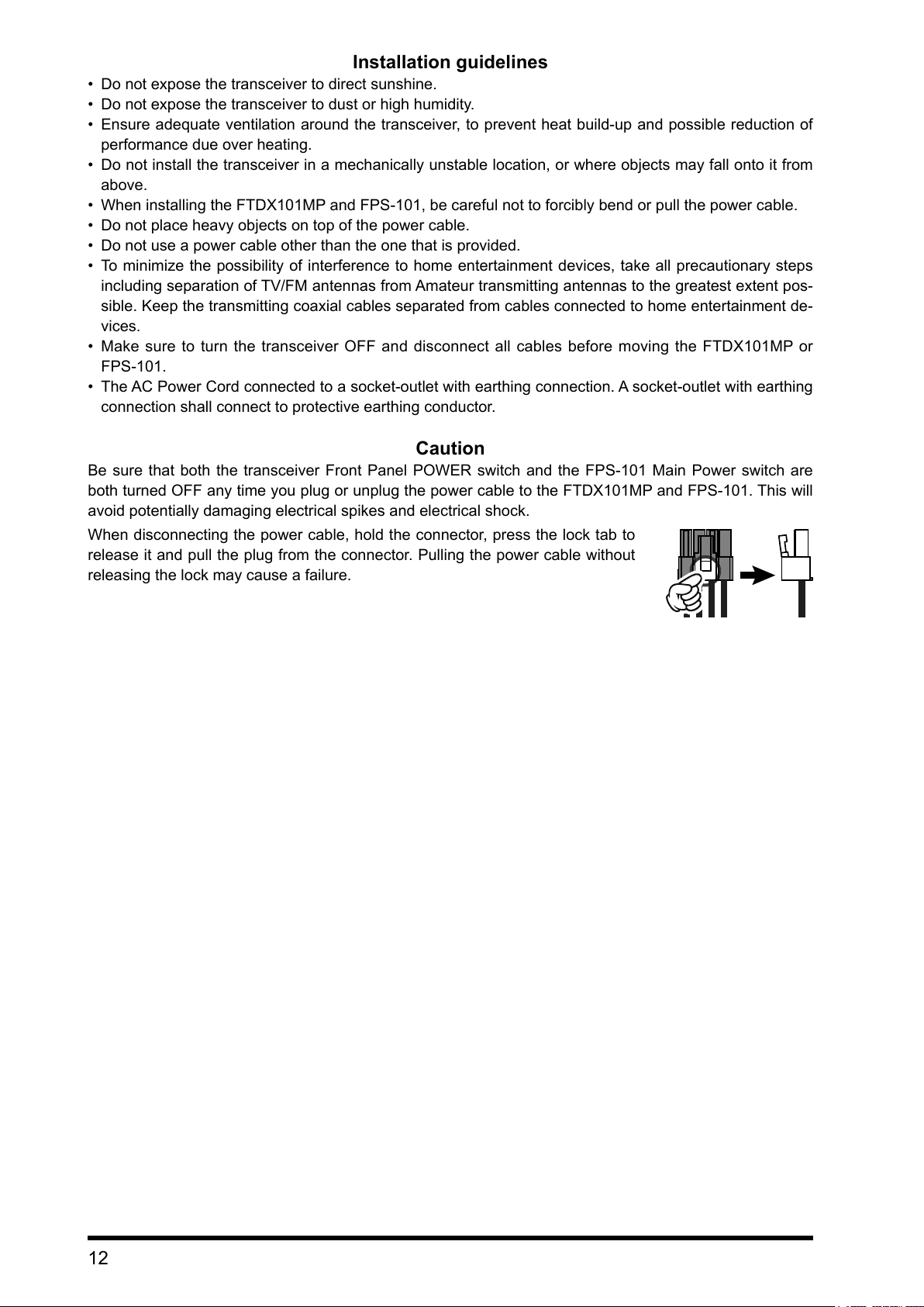
Whendisconnecting thepowercable,holdtheconnector,pressthelocktabto
releaseitandpulltheplugfromtheconnector.Pullingthepowercablewithout
releasingthelockmaycauseafailure.
12
Page 18

Microphone, Headphone, Key, Keyer and FH-2 Connections
φ6.3mm
MIC
SW1
MIC GND
+5V
SW2
PTT
GND
FAST
(as viewed from front panel)
ANT 1 ANT 2
EXT SPKR KEY
A B
Remote Control Keypad
FH-2
REM
METER
EXT ALC RS-232C
PTT
+13.8V
GND
LINEAR
ACC TUNER
Key-up voltage on the front key jack is approximately +3.3 V DC, and key-down current is approximately 1 mA.
Key-up voltage on the rear key jack is approximately +5.0 V DC, and key-down current is approximately 3 mA.
13
Page 19

Linear Amplier Interconnections
“CT-178” Connection Cable (option)
Coaxial Cable (50 ohm)
VL-1000
Be sure that both the FTDX101 series and VL-1000 are turned OFF, and then follow the installation recom-
mendations contained in the bellow illustration.
• VL-1000 Linear Amplier Interconnections
Since the FTDX101MP has a high transmission output of 200 W, be sure to turn ON the ATT switch of the VL-
1000. Using the amplier with the ATT switch “OFF” may damage the VL-1000.
• Refer to the VL-1000 Operating Manual for details regarding amplier operation.
• Do not attempt to connect or disconnect coaxial cables when your hands are wet.
Connect to “INPUT 2” of the VL-1000
HF/50MHz Antenna
ANT 1
ANT 2
ANT 1
ANT 3
INPUT 2
ANT 1 ANT 2
GND
DC IN
GND GND
EXT SPKR KEY
A B
LINEAR
LINEAR ALC 2BAND-DATA 2
EXT ALC RS-232C
METER
REM
PTT
+13.8V
ACC TUNER
The figure above shows the FTDX101MP rear panel connections with the VL-1000.
DC 48V IN
VP-1000
CONTROL
14
Page 20

• Interfacing to Other Linear Ampliers
Antenna Cable (50 ohms)
Coaxial Cable (50 ohm)
• The TX GND OUT pin (pin 2) of the LINEAR jack is a transistor “open collector” circuit. It is capable of
handling positive relay coil voltages up to +60VDC at 200 mA or +30 VDC at 1 A.
• When using multiple linear ampliers for different bands, you must provide external band switching of the
“Linear Tx” relay control line from the “TX GND OUT” line at the LINEAR jack.
Do not exceed the maximum voltage or current ratings for the “TX GND OUT” pin (pin 2) of the LINEAR jack.
This line is not compatible with negative DC voltages, or AC voltages of any magnitude.
HF/50 MHz Antenna
ANT 1
RF OUT RF IN
GND
GND
ANT 1 ANT 2
DC IN
EXT SPKR KEY
A B
LINEAR
LINEAR
D-sub 15 pin
EXT ALC RS-232C
METER
REM
PTT
+13.8V
ACC TUNER
GND
The figure above shows the FTDX101MP rear panel connections to other linear amplifiers.
HF/50 MHz Antenna
ANT 1
ANT 1 ANT 2
EXT SPKR KEY
A B
LINEAR
EXT ALC RS-232C
METER
REM
PTT
+13.8V
ACC TUNER
RF OUTRF IN
GND
EXT ALC
TX GND
GND
DC IN
GND
TX GND
EXT ALC
GND
The figure above shows the FTDX101MP rear panel connections to other linear amplifiers.
15
Page 21

Rear Panel
The figure above shows the rear panel of the FTDX101MP.
SIGNAL
GND
GND
COMMON
GND
DATA IN
GND
DATA OUTSQL
GND
ANT 1 ANT 2
GND
Cooling FAN
ANT 1, 2, 3/RX
Connect the main antenna(s) here, using type-M
(PL-259) connectors and coaxial feed lines. The
internal antenna tuner affects only the antenna(s)
connected here, and only during transmission.
EXT SPKR
This 3.5-mm, 2-contact, jacks provide audio output
for external loudspeakers. The impedances at the
jacks are 4 - 8 Ohms, and the volume varies ac-
cording to the setting of the front panel [AF] knob.
DOT
METER
EXT ALC RS-232C
PTT
+13.8V
EXT SPKR KEY
A B
LINEAR
AF-OUT
REM
ACC TUNER
DASH
When connecting an electronic keyer paddle
This 3.5-mm, 3-contact jack provides dual-channel
low-level receiver output, for recording or external
amplication.
The front panel [AF] knobs do not affect
the signals at this jack (300 mVp-p at 10
k-ohms).
Inserting plugs into the jacks alters the inter-
nal loudspeaker conguration.
Depending on the plugs connected to the jacks, the
conguration of the internal and external speakers
varies.
Internal
Speaker
Connect to
A only
Connect to
B only
Connect to
both A and B
KEY
A B
MAIN and
SUB audio
- MAIN audio SUB audio
SUB audio MAIN audio -
- -
This 1/4-inch 3-contact jack accepts a CW key or
keyer paddle. A two-contact plug cannot be used
in this jack. Key-up voltage is +5.0 V DC, and key-
down current is 3 mA.
KEY
NC
When connecting a single straight key
AUDIO (MAIN)
AUDIO (SUB)
REM
By plugging the FH-2 Remote Control Keypad into
this jack, direct access to the FTDX101 CPU is pro-
vided for control functions of the contest memory
keying, and also frequency and function control.
RTTY/DATA
This 6-pin input/output jack accepts AFSK input
from a Terminal Node Controller (TNC); it also pro-
vides fixed level receiver audio output, and FSK
keying line.
PTTSHIFT
METER
This 3.5-mm jack is to connect an external meter.
The meter display is output as an analog voltage (0
V to about 3 V).
Insert appropriate resistors in series according to
the meter you use.
SIGNAL (MAIN)
SIGNAL (SUB)
16
Page 22

SERIAL OUT
SERIAL IN
RTSCTS
50V
GND
BAND DATA B
GND
NC
Power ON
3.3V
13.8V
TUNER SENSE
RESET OUT
RX D
EXT ALC
This RCA input jack accepts negative-going exter-
nal ALC (Automatic Level Control) voltage from a
linear amplifier to prevent over-excitation by the
transceiver. Acceptable input voltage range is 0 to
-4 VDC.
USB
Connecting to a computer from this jack with a
commercially available USB cable allows remote
control by CAT commands from the computer. The
jack can also be used for input and output of audio
signals and transmitter control. A USB driver is re-
quired for remote control from a computer. Down-
load the driver from the Yaesu website (http://www.
yaesu.com).
RS-232C
This 9-pin serial DB-9
jack permits external
computer control of the
FTDX101. Connect a
serial cable here and
to the RS-232C COM
port on your personal
computer (no external
interface is required).
GND
Use this terminal to connect the transceiver to a
good earth ground, for safety and optimal perfor-
mance. Use a large diameter, short braided cable
to make ground connections.
DC IN
This is the DC power supply connection for the
transceiver.
FTDX101MP
Connect the supplied
external power supply
“FPS-101” using the
supplied DC cable.
FTDX101D
Use the supplied DC cable
to connect directly to a DC
power supply, which must be
capable of supplying at least
23 A @13.8 VDC.
RX OUT (MAIN)
This RCA jack provides output of the RF signal. For
connecting an external receiver and the like.
LINEAR
This 15-pin output jack provides band selection
data, which may be used for control of optional ac-
cessories such as the VL-1000 Solid-state Linear
Amplier.
GND
N/AGND
N/A
N/A
NC
13.8V
ACC
This 13-pin jack may be connected to an external
device.
GND
DATA1
DATA2
CLOCK
CS
IF OUT (MAIN)
This RCA jack outputs the receiver 9.005 MHz IF
signal. This signal does not pass through the roof-
ing lter.
TX-GND
This RCA jack’s center pin is closed to ground while
the transceiver’s transmitter is engaged. The tran-
sistor open collector circuit used for this jack is ca-
pable of switching a DC voltage of 60 V at 200 mA,
or DC 30 V at up to 1Amp.
PTT
This RCA input jack may be used to provide manu-
al transmitter activation using a foot switch or other
switching device. Its function is identical to the
[MOX] key on the front panel. Open-circuit voltage
is 5 VDC, and closed-circuit current is 3 mA.
RX OUT (SUB)
This RCA jack provides output of the RF signal. For
connecting an external receiver and the like.
+13.8V
This RCA output jack provides regulated, sepa-
rately fused 13.8 VDC at up to 200 mA, to power
an external device such as a packet TNC. Make
sure your device does not require more current (if it
does, use a separate power source).
TUNER
This 8-pin output jack is used for connection to the
FC-40 External Automatic Antenna Tuner.
TX INH
TX D
EXT-DISPLAY
DVI-D connector for connecting an external moni-
tor.
When using an external monitor, set the setting
menu item “EXT DISPLAY” (page 105) to “ON”.
Connect a monitor that supports 800 x 480
resolution or 800 x 600 resolution.
GND
+13V OUTTX GND
Reserve
Reserve
CNT RX
CNT TX
Reserve
+13.5V OUT
TX GND
GND
BAND DATA A
BAND DATA C
BAND DATA D
TX INH
GND
TX REQ
NC
NC
EXT ALC
IF OUT (SUB)
This RCA jack outputs the receiver 8.900 MHz IF
signal. This signal does not pass through the roof-
ing lter.
17
Page 23

SSM-75G Microphone Switches
MUTE
P1 P2 P3 P4
PTT Switch
Switches Transmit/Receive.
Press to transmit and release to receive.
DWN / UP Key
The [UP]/[DWN] keys may also be used to manual-
ly scan the frequency upward or downward.
● Pressing the [FAST] key engages the “Fast” tun-
ing selection.
● The amount of frequency change depends on the
operation mode (default setting: see table below).
Operating Mode UP DWN
CW / SSB / RTTY
DATA-L / DATA-U / PSK
AM / FM
DATA-FM
Numbers in parentheses indicate steps when the [FAST]
key is On.
● The frequency change can be changed in the
setting menu.
Operating Mode Memu Item Step
SSB / CW
RTTY / PSK
DATA-L
DATA-U
AM
FM
DATA-FM
SSB/CW DIAL STEP
AM CH STEP
FM CH STEP
+10
[+100Hz]
+5kHz
+50kHz
[
(page 103)
(page 103)
(page 103)
Hz
]
-10Hz
[-100Hz]
-5kHz
[-50kHz]
5/10 (Hz)
2.5/5/9/10/
12.5/25 (kHz)
5/6.25/10/
12.5/20/25
(kHz)
MUTE Key
While pressing the MUTE key, the receiver audio
from the speaker will be muted.
Microphone
Speak into the microphone in a normal tone of
voice with the microphone 5 cm away from the
mouth.
P1 key
Switches the operation to the MAIN band.
It is the same function as the [MAIN] key on the
front panel of the transceiver.
P2 key
Switches the operation to the SUB band.
It is the same function as the [SUB] key on the front
panel of the transceiver.
P3 key
Switches transmission to the MAIN band.
It is the same function as the MAIN band [TX] key
on the front panel of the transceiver.
P4 key
Switches transmission to the SUB band.
It is the same function as the SUB band [TX] key
on the front panel of the transceiver.
18
Page 24

Speaker
Be sure to study this information to maximize
the receiver performance of the high-class
FTDX101 series shortwave transceiver.
Narrow band SDR receiver signal flow and the specific
functions that affect receiver performance.
Narrow Band SDR
RF
AMP
Mixer
Antenna
Selector
VC-Tune
ATT A/D SDR D/ADSP
BPF
Roofing
Filter
Use the VC TUNE
VC-Tune can attenuate interfering signals directly at the receiving
frequency. VC-Tune can be turned ON to attenuate the strong jam-
ming signals that cannot be removed even with the BPF. If there is
no disturbing signal, turn it OFF. Operation is performed with the
outside MPVD ring of the Main Dial.
AMP
BPF (Band Pass Filter)
BPF is selected automatically. When a frequency band is selected
on the front panel, the BPF (Band Pass Filter) for that band is auto-
matically connected to the antenna circuit.
Use the ROOFING FILTER
Roofing filters attenuate strong signals that are outside of the de-
sired passband after converting to the 9MHz IF.
Received signal flow
The roofing filter can attenuate unwanted frequency components.
Touch [R.FIL] on the TFT screen to select the 3kHz lter for SSB,
the 1.2kHz lter or the 600Hz lter for CW. An optional 300Hz* lter
is also available. * Included with FTDX101MP.
Use DSP interference removal functions
DSP interference removal functions include IF SHIFT, IF WIDTH, IF
NOTCH, APF, CONTOUR, and DNR.
Use these functions to adjust for comfortable reception while listen-
ing to the received audio.
To change the sound quality of the received audio, use the CON-
TOUR function to easily improve the sound quality with high and
low frequency cut or emphasis.
19
Page 25

Display Indications
Meter Operations during Transmission
Meter operation during transmit
PO
ALC
AMC gain control display
Meter & Filter images
Frequency area
Function settings
Spectrum Scope
Display setting keys
Display setting keys
Meter Display
S-Meter
(MAIN band)
Final transistor
temperature
Speech compressor level
When the meter display screen is touched, the transmit meter selection screen is shown (the default default
setting is “PO” on the left and “ALC” on the right).
RF power Output Relative ALC voltage Final amplifier drain voltage
S-Meter
(SUB band)
Final amplifier drain current
Standing Wave Ratio
20
(Displays compression level during speech processor operation)
Make adjustments with the [PROC / PITCH] control.
RF power Output
Final transistor
LEFT METER RIGHT METER
PO COMP
temperature
TEMP ID
Relative ALC voltage
ALC
Final amplifier drain current
VDD
SWR
Final amplifier drain voltage
Standing Wave Ratio
Page 26

Filter Function Display
Clear all entered numbers.
SSB Mode
Roofing filter bandwidth
CW Mode RTTY Mode PSK/DATA Mode
Displays the passband status of the DSP lter. The operation of WIDTH, SHIFT, NOTCH, CONTOUR etc.
can be observed.
The current roofing filter
bandwidth is displayed as
a blue line below the lter
function display.
The roong lter is select-
ed by touching [R. FIL].
Touch the lter function display to toggle between “normal display” and “magnied display”. Touch again to re-
turn to the “normal display”.
• Display only DSP lter bandwidth information
To display only the DSP lter bandwidth information, press and
hold the spectrum area of the lter function display to clear the
spectrum view. To display it, press and hold again.
DSP filter bandwidth
Frequency Display
The transmit and receive frequencies of the MAIN Band are shown on the left and the transmit and
receive frequencies of the SUB Band are shown on the right.
In split operation, the transmit frequency is displayed in red.
• Keyboard Frequency Entry
1. Touch the “Hz” area of the frequency display.
2. Enter the frequency using the numeric keys.
Erases the rightmost digit.
The entered frequency is
confirmed.
The display returns to the
previous screen when
back is touched.
● If there is no operation within 10 seconds,
the input will be canceled.
3. Touch [ENT] to conrm.
● A short-cut for frequencies ending in zero -
press the [ENT] key after the last non-zero
digit.
Example:
To enter 7.00.000MHz
[0] →[7]→[ENT] or [7] → [.] → [ENT]
To enter 7.03.000MHz
[7] →[.]→[0]→[3]→[ENT]
• Tuning in 1 MHz or 1 kHz Steps
To temporarily set the dial knob to 1MHz or 1kHz
steps, touch the “MHz” or “kHz” area of the fre-
quency display.
Touch “MHz” or “kHz” area of the frequency dis-
play to confirm. If there is no operation within 3
seconds, the frequency will be xed.
• Touch the Frequency Display of the inactive
band to change the Operating Band with one
touch.
• Touch the Scope Screen, to easily move to
the touched frequency.
21
Page 27

Important Receiver Settings
Important setting items when receiving
The status of various operations that are important during receive, are shown at the bottom of the display.
To change a setting, touch the appropriate location on the display.
ANT (Switching the Antenna)
The currently used antenna terminal number
(“ANT 1” “ANT 2” “ANT 3 / RX”) is displayed.
After touching ANT, touch the desired number.
The antenna can be set separately for each oper-
ation band.
The antenna terminal “ANT 3 / RX” can be set
to “Receive Only” (Set Menu: “ANT 3 SELECT”
page 97).
ATT (Attenuator)
Displays the current ATT (Amount of receive input
signal attenuation).
When the desired signal is extremely strong or
the noise level is high on a low frequency band,
activate the attenuator to reduce the incoming
signal or noise from the antenna.
After touching [ATT], touch the desired attenua-
tion amount.
The attenuator is set independently for each op-
eration band.
OFF Attenuator is Off
6dB
12dB
18dB
The incoming signal power is reduced by
6dB (Signal voltage reduced to 1/2)
The incoming signal power is reduced by
12dB (Signal voltage reduced to 1/4)
The incoming signal power is reduced by
18dB (Signal voltage reduced to 1/8)
IPO
The IPO (Intercept Point Optimization) function
can establish the gain of the RF amplier section
to accommodate the connected antenna and the
received signal conditions. IPO can be selected
from three operating conditions.
AMP1: One stage RF amplifier is connected.
This is a well-balanced operation of re-
ceiver sensitivity and characteristics (Ap-
proximately 10 dB gain).
AMP2: Two RF amplifiers are connected in se-
ries to give top priority to sensitivity (Ap-
proximately 20 dB gain).
IPO: The received signal is input to the IF mix-
er without passing through the RF ampli-
fier. This can greatly improve receiving,
especially in the harsh low band signal
environment.
After touching [IPO], touch the desired operating
condition.
• IPO is set independently for each operation
band.
• Normally, select “AMP1”.
• The IPO can not only attenuate the input sig-
nal but also improve the intermodulation char-
acteristics. It is most effective to operate the
IPO rst, and then use the ATT if the signal is
still too strong. The noise level can be attenu-
ated and S/N greatly improved.
• If the noise level is high or the received signal
is extremely strong, the incoming signal level
can be suppressed with the IPO/ATT settings.
If the S-meter fluctuates S-3 or more in the
noise level, or the received signal is extremely
strong and it causes a high S-meter indication
(+20dB or more), activate the attenuator.
• Since IPO does not only attenuate the incom-
ing signal, but also improves the cross mod-
ulation characteristic, try to activate the IPO
first. If the signal is still strong, also use the
ATT. In this way, you can attenuate the incom-
ing signal and noise effectively.
22
Page 28

R.FIL (
Roong Filter Switching
)
AGC (
Automatic Gain Control
)
Displays the bandwidth of the currently selected
roong lter.
Switches the crystal roofing filters of 300Hz*,
600Hz, 1.2kHz*, 3kHz, and 12 kHz that are in-
stalled in this transceiver.
Normally, filters are automatically switched de-
pending on the operation mode, however the lter
may be changed according to the conditions or
when an optional lter is installed.
Roofing filters are to be set independently for
each operation band.
* 300Hz & 1.2kHz roofing filters are optional.
(300Hz is included on the MAIN side with the
FTDX101MP)
After touching [R. FIL], touch the desired lter.
If the optional 300Hz and 1.2kHz filters are not
installed, “300Hz” and “1.2kHz” will not be dis-
played.
Displays the currently selected AGC setting.
The AGC system is designed to help compen-
sate for fading and other propagation effects. The
AGC characteristics can be individually set for
each operating mode. The basic objective of AGC
is to maintain a constant audio output level once
a certain minimum threshold of signal strength is
achieved.
After touching [AGC], touch the desired time con-
stant.
● AGC can be set for each operation band.
● The “AUTO” selection mode selects the opti-
mum receiver-recovery time for the reception
mode.
Operating Mode AUTO AGC Selection
SSB / AM SLOW
CW / FM / DATA-FM FAST
RTTY / PSK
DATA-L / DATA-U
Normally, AGC is set to “AUTO”, which auto-
matically selects the time constant according to
the received signal type, but when receiving a
weak signal or when there is noise and fading,
the AGC action may be changed according to
the reception condition at that time. Change the
time constant to make received signals most
audible
MID
Several aspects of AGC performance may be
configured via the Menu. However, because
AGC can have such a profound impact on over-
all receiver performance, we generally do not
recommend any changes to the AGC Menu se-
lections until you are thoroughly familiar with the
performance of the FTDX101.
23
Page 29

Scope Display Setting
In addition to the conventional two-dimensional waterfall spectrum display, Yaesu has added the 3-Dimen-
sion Spectrum Stream (3DSS) color display. The constantly changing band conditions and signals are
depicted in real time and color. The frequency span is shown on the horizontal X axis, the vertical Y axis
depicts the signals and their strengths, and the time is represented on the receding Z axis. The FTDX101
operator can intuitively grasp the band and signal conditions at any instant.
When VC Tune operates, the steep attenuation characteristics of VC Tune may cause some signals in the
spectrum scope to be attenuated and disappear, or the screen may not look uniform, but this is not a malfunc-
tion.
CENTER/CURSOR/FIX
Switches the Spectrum Scope operation each time the key is touched.
• When the display area is touched, the receive frequency is moved to that point.
• In CENTER mode, the frequency touched becomes the center.
• In CURSOR and FIX mode, the marker and the receive frequency move to the touched position.
• Press and hold the [FAST] key in the CENTER and CURSOR modes, the Hz digit of the receive frequency
will be “0”.
• Press and hold the [FAST] key in FIX mode, the receive frequency returns to the start frequency of the dis-
play area.
• CENTER
The receive frequency is always shown at the cen-
ter of the screen and spectrum display. The band
spectrum is shown within the range set by “SPAN”.
The CENTER mode is convenient for monitoring
the situation around the operating frequency.
• CURSOR
Monitors the spectrum within the range set with
“SPAN”. When the frequency (marker) exceeds
the upper limit or the lower limit of the range, the
screen is automatically scrolled and the status out-
side the setting range can be observed.
MAIN or SUB
Marker*
Current display mode (CENTER)
Sweep Speed
Scope Screen frequency span (display range).
*: At factory shipment, marker display is ON.
24
MAIN or SUB
The lower limit frequency of the display area.
Marker* (Receive Frequency)
Marker* (Transmit Frequency)
Current display mode (CURSOR)
Sweep Speed
Scope Screen frequency span (display range).
The upper limit frequency of the display area.
*: At factory shipment, marker display is ON.
Page 30

• FIX
To use Fixed Mode, enter the start frequency of the
scope.
MAIN or SUB
Display area start frequency
Marker* (Reception Frequency)
Current display mode (FIX)
Sweep Speed
Scope Screen frequency span (display range).
The upper limit frequency of the display area.
*: At factory shipment, marker display is ON.
3DSS
Switch between the 3DSS display and the waterfall
display.
The display will change each time it is touched:
To adjust the level of the SUB band, press
the [SUB] key to make the operation band a
SUB band.
3DSS type
Waterfall type
Each time the Waterfall Display is touched,
the size of the display changes as follows.
FIX is displayed at the top of the scope screen.
Press and hold [FIX] while FIX is displayed, the fre-
quency input screen will be displayed, and the start
frequency can be entered:
Example:
To enter 7.000.000 MHz
[0] →[7]→[ENT] or [7] → [.] → [ENT]
To enter 7.030.000 MHz
[7] →[.]→[0]→[3]→[ENT]
In FIX mode, If the [FAST] key is held, the
receiver returns to the start frequency.
SPAN
Set the frequency span (display range) of the scope
screen. After touching, select the desired span.
The display level changes when SPAN is
changed, so reset the optimum display level
with [LEVEL] each time.
à à
MONO (Dual/Mono Switching)
Touch to switch the display to “Mono” and show
only the MAIN band.
Touch again to display both MAIN and SUB Bands.
Dual
Mono
25
Page 31

MULTI
Touch this area to set the level and sweep speed.
In addition to the scope display, the oscilloscope
and AF-FFT are also presented.
Touch again to return to the original screen.
Touch this area to set the attenuator.
EXPAND
The display area of the scope screen may be ex-
panded vertically.
Touch to expand the display. Touch again to return
to the original.
HOLD
Temporarily stops the operation of the Scope Dis-
play and the Filter Function Display. Touch the dis-
play to enter HOLD state, touch it again to restore
Scope operation.
During HOLD, “HOLD” ashes.
DISP
Each time the key is pressed, the Scope Screen
Display changes as shown below.
Press the [SUB] key to adjust the SUB band
level.
ence
Only “MAIN” or “SUB” will be displayed
à
refer-
Normal Display
Larger View
Upper side: SUB, Lower side: MAIN
Left side: MAIN, Right side: SUB
Left side: MAIN, Right side: SUB
à
à
26
Page 32

S.MENU
S.MENU key
SCOPE MENU display
Receive Frequency Transmit Frequency
Narrow band SDR setting area
On the SCOPE MENU screen, enter settings related to the Scope Display.
Press the [S.MENU] key to display the SCOPE MENU screen. Touch the desired item to set.
MULTI knob
Operation display
MULTI knob
SPEED
Sets the Scope Display sweep speed. After touch-
ing, select the desired speed.
SLOW1: sweep speed Slow
SLOW2: sweep speed ↑
FAST1: sweep speed Normal
FAST2: sweep speed ↓
FAST3: sweep speed Fast
Overall setting area
PEAK
The color density may be adjusted to the level of
the signal. Touch PEAK and then select the desired
color concentration.
LV1 : Thin
LV2 : ↑
LV3 : Normal
LV4 : ↓
LV5 : Dark
MARKER
Displays markers that indicates the position of the
current receive and the transmit frequencies in the
spectrum.
Normally leave it ON.
COLOR
Touch COLOR and select the desired color from
the Display Color selection panel. The screen panel
will disappear automatically after about 3 seconds.
The color to be displayed for the Direct Sam-
pling SDR, and for the Narrow Band SDR can be
changed on the Color Selection Panel.
1. Press the [S.MENU] key to display the SCOPE
MENU.
2. Touch [COLOR].
3. Touch the desired color from the selections on
the screen.
To change the color of the Narrow Band SDR,
touch and desired color block.
Favorite color combinations can be registered in
the menu by pressing and holding M-1, M-2 or M-3.
Even when the color is not changed, the Narrow
Band SDR information is displayed.
LEVEL
Adjust the level to make it easier to distinguish between
the desired signal and noise. The display level changes
depending on antenna gain, condition, frequency band,
SPAN and so on.
Always adjust the LEVEL for the best image on the
screen.
Touch LEVEL, and then turn the [MULTI] knob to select
the desired level.
• On the 3DSS screen, weak signals may be
more easily observed by adjusting the LEVEL
so that the noise level can be seen only a lit-
tle, so always adjust the LEVEL and use it at
the optimum position.
• Be sure to make adjustments when changing
bands or changing SPAN.
• If the level is changed, the signal strength
also appears to change, but it does not affect
the actual signal input level.
27
Page 33

Function Menu Display
FUNC key
Operation of the MULTI knob
MULTI knob
Press the [FUNC] key to call up the function screen for setting various functions. The setting menu (page 88) is
also called from the function screen. Press again to return to the normal operation screen.
Touch a MENU item, or rotate the [MULTI] control knob to make a selection.
Operation of the Display MULTI Knob
[MULTI] displays the operation of the [MULTI] knob.
Normally, it is recommended to adjust the level of the spectrum scope as the [LEVEL] knob control of [S.MENU].
The last function used is stored in the [MULTI] control, it can easily set by operating the [MULTI] control.
MULTI knob
The following settings and operations can be performed with the [MULTI] control.
SPEED*: Set Scope Sweep Speed.
PEAK*: Adjust the Peak Signal Color Density.
MARKER*: ON/OFF Marker indicates the transmit
and receive frequency position within the
Scope Display image.
COLOR*: Changes the scope display color.
LEVEL*: Adjust the reference level to make it eas-
ier to distinguish the scope display target
signal from the noise.
*These items may be called up by pressing the
[S.MENU] key.
RF POWER: Transmit power setting
MONI LEVEL: Monitor level adjustment
DNR LEVEL: DNR level setting
NB LEVEL: Noise blanker level setting
VOX GAIN: VOX gain setting
VOX DELAY: VOX delay setting
ANTI VOX: Anti-VOX Settings
STEP DIAL: Frequency change at predetermined
frequency step
MEM CH: Memory channel selection
GROUP: Memory group selection
R. FIL: Roong lter bandwidth selection
28
Page 34

Other On-Screen Indications
BUSY: Lights up while receiving a signal.
TX: Lights up during transmission.
+: Lights in plus shift (repeater operation).
-: Lights in negative shift (repeater opera-
tion).
ENC: Lights when the tone encoder is operat-
ing.
TSQ: Lights during tone squelch operation.
CLAR TRX: Lights when the TRX clarier is in opera-
tion.
CLAR TX: Lights up during TX clarier operation.
CLAR RX: Lights up during RX clarier operation.
+ xxx Hz /-xxx Hz:
Displays the offset amount of the clarier.
HI-SWR: A warning display to indicate an antenna
system error.
VFO: Lights in VFO mode.
M-xx: Displays the selected channel number in
memory mode.
MT: Lights up during memory tuning opera-
tion.
QMB: Lights up during operation with quick
memory.
PMS: Lights up during programmable memory
scan operation.
EMG: Emergency call set frequency call lights
up.
LSB / USB / CW-L / CW-U / AM / AM-N / FM / FM-N /
DATA-L / DATA-U / DATA-FM /D-FM-N /
RTTY-L / RTTY-U / PSK:
Displays the selected radio emission
type.
About TFT Displays
FTDX101 series utilizes a TFT liquid-crystal display.
Although TFT liquid-crystal displays are made using very precise technology, they are prone to
develop dead pixels (dark dot) or pixels that are always on (bright dot). Please understand that
such phenomena do not constitute product defects or malfunctions. Rather, this phenomena
occurs due to limitations in the manufacturing technology with respect to TFT liquid-crystal dis-
plays.
• Depending on the viewing angle, unevenness in color or brightness may occur. Please note that
any unevenness observed is inherent to the construction of TFT liquid crystal displays and there-
fore does not constitute a product defect or malfunction.
• If your TFT liquid-crystal display becomes dirty, please use a dry soft cloth or tissue to wipe the
display clean. Use of glass cleaner, household cleaners, organic solvents, alcohol, abrasives,
and/or like substance may damage the TFT liquid-crystal display.
29
Page 35

Screen Saver
LIGHT
A Screensaver, to prevent burning of the TFT
screen will operate after a set time, if no trans-
ceiver function is operated.
1. Press the [FUNC] key.
2. Select [DISPLAY SETTING] → [DISPLAY] →
[SCREEN SAVER].
3. Select the time until the screen saver is em-
ployed (default setting is 60 min).
OFF Screensaver is not employed.
15min Screensaver activates after 15 minutes.
30min Screensaver activates after 30 minutes
60min Screensaver activates after 60 minutes
4. Press the [FUNC] key to save the new setting
and exit the Setting Menu.
5. Press the [FUNC] key to exit to normal operation.
Font setting for
frequency display
The height of the frequency display can be varied.
BOLD (Default)
1. Press the [FUNC] key.
2. Select [DISPLAY SETTING]→[DISPLAY]→
[FREQ STYLE].
3. Select “LIGHT” or “BOLD”.
4. Press the [FUNC] key to save the new setting
and exit the Setting Menu.
5. Press the [FUNC] key to exit to normal operation
.
Adjust contrast
Adjust the contrast of the TFT display.
1. Press the [FUNC] key.
2. Select [DISPLAY SETTING]→[DISPLAY]→
[TFT CONTRAST].
3. Turn the [MULTI] knob to adjust the contrast
(default setting is 10).
4. Press the [FUNC] key to save the new setting
and exit the Setting Menu.
5. Press the [FUNC] key to exit to normal operation.
Adjusting the brightness
(Dimmer)
Adjust the brightness of the TFT display and LED
indicators.
1. Press the [FUNC] key.
2. Select [DISPLAY SETTING]→[DISPLAY].
3. Select the item whose brightness you want to
adjust.
TFT DIMMER Display (default 15)
LED DIMMER LED indicators
4. Turn the [MULTI] knob and adjust the bright-
ness.
5. Press the [FUNC] key to save the new setting
and exit the Setting Menu.
6. Press the [FUNC] key to exit to normal operation.
(default
10)
Inputting the Call Sign
Registered call signs names, and characters can
be displayed on the opening screen when the
power is turned ON.
1. Press the [FUNC] key.
2. Select [DISPLAY SETTING] →[DISPLAY] →
[MY CALL].
3. Touch a character key. The touched character
will be displayed at the top of the screen. En-
ter each character of your call sign.
Up to 12 characters (letters, numbers, and
symbols) can be entered.
Caps
BACK
Space Insert space
ENT
The input switches between lower and
upper-case letters each time this symbol is
touched.
One character to the left of the cursor is
erased when this symbol is touched.
The display returns to the previous screen
when this symbol is touched.
The cursor in the input eld moves left or
/
right when these symbols are touched.
The entered characters are conrmed and
the display returns to the previous screen
when this symbol is touched.
30
4. Touch [ENT] .
5. Press the [FUNC] key to save the new setting
and exit the Setting Menu.
6. Press the [FUNC] key to exit to normal operation.
Page 36

Note
31
Page 37

Front Panel Controls & Switches
COMMON
GND
GND
FAST
MIC
ON/OFF Switch
Press and hold this switch for one second to turn
the transceiver ON or OFF.
USB Jack
Connect a USB A type keyboard or mouse. They
can be used to select items on the screen or to en-
ter characters.
KEY
Connect a telegraph key or electronic keyer paddle
to use for CW mode operation.
When connecting a key or other device to
the KEY jack, use only a 3-contact (“ste-
reo”) 3.5 mm phone plug; a 2-contact plug
will place a short between the ring and the
(grounded) shaft of the plug, resulting in a
constant “key-down” condition.
DOT
DASH
Refer to the “Scope display setting”
(page 24).
PHONES Jack
Connect headphones to this standard ϕ6.3 stereo
jack.
Inserting a headphone plug into this jack will deacti-
vate the internal and external speakers.
When wearing headphones, we recommend
that you turn the AF Gain levels down to
their lowest settings before turning power
ON, to minimize the impact on your hearing
caused by audio “pops” during switch-on.
AUDIO (MAIN)
AUDIO (SUB)
MIC
This 8-pin jack accepts input from a microphone uti-
lizing the traditional YAESU HF transceiver pinout.
SW1
MIC GND
32
KEY
NC
Key-up voltage is approximately +3.3 V
DC, and key-down current is approximately
1 mA.
+5V
SW2
PTT
GND
Page 38

TUNE
This is the ON/OFF switch for the FTDX101 Auto-
matic Antenna Tuner.
Press the [TUNE] key briey to activate the antenna
tuner. Press the [TUNE] key briey again to disable
the antenna tuner.
Press the [TUNE] key for about 1 second to start
“automatic tuning”.
Since the transceiver transmits automati-
cally during automatic tuning, make sure to
connect an antenna or dummy load before
tuning up.
When the antenna or dummy load does not
match the impedance, “HI-SWR” will appear
on the touch panel.
VOX
This key enables automatic voice-actuated trans-
mitter switching. While VOX is activated, the LED
inside this key glows orange.
1. Press the [VOX] key.
VOX feature is activated
2. Without pressing the PTT switch, speak into the
microphone in a normal voice level. When you
start speaking, the transmitter should be activat-
ed automatically.
When you finish speaking, the transceiver
should return to the receive mode (after a short
delay).
To cancel VOX and return to PTT operation,
press the [VOX] key once more.
MOX
Pressing this key engages the PTT (Push to Talk)
circuit to activate the transmitter.
ZIN/SPOT
ZIN
Press the [SELECT] switch momentarily to adjust
the receiving frequency and zero-in automatically
while receiving a CW signal.
SPOT
While pressing and holding [SPOT], the tone is
output from the speaker. This tone corresponds to
the pitch of your transmitted signal. If you adjust the
receiver frequency until the pitch of the received
CW signal matches that of the Spot tone, the trans-
mitted signal will be precisely matched to that of the
other station.
SD memory card slot
You can use the commercially available SD memo-
ry card to save various settings, save the memory
contents, screen capture and update the rmware.
• The SD card is not provided with the prod-
uct.
• Not all SD cards sold commercially are
guaranteed to work with this transceiver.
• Adjusts the VOX GAIN
The VOX Gain may be adjusted to prevent unin-
tended transmitter activation in a noisy environ-
ment. To adjust the VOX Gain:
1. Press the [FUNC] key.
2. Touch [VOX GAIN] .
3. While speaking into the microphone, rotate the
[MULTI] knob to the point where the transmitter
is quickly activated by your voice, without back-
ground noise causing the transmitter to activate.
• Adjusts the VOX Delay Time
The “Hang-Time” of the VOX system (the trans-
mit-receive delay after the cessation of speech)
may also be adjusted.
To set a different delay time:
1. Press the [FUNC] key.
2. Touch [VOX DELAY] .
3. Rotate the [MULTI] knob while saying a brief syl-
lable like “Ah” and listening to the hang time for
the desired delay.
• Adjusts the VOX anti-trip sensitivity
The Anti-Trip setting sets the negative feedback
of receiver audio to the microphone, to prevent re-
ceiver audio from activating the transmitter (via the
microphone).
1. Press the [FUNC] key.
2. Touch [ANTI VOX] .
3. Rotate the [MULTI] knob to prevent receiver au-
dio from activating the transmitter (via the micro-
phone).
33
Page 39

MAIN dial
The MAIN dial sets the operating frequency.
Rotate the MAIN dial knob to tune within the band,
and begin normal operation.
● Pressing the [FAST] key engages the “Fast” tun-
ing selection.
● The amount of frequency change depends on the
operation mode (default setting: see table below).
Operating Mode 1 Step 1 Dial Rotation
LSB / USB / CW
DATA-L / DATA-U
RTTY / PSK
AM / FM
DATA-FM
Numbers in parentheses indicate steps when the [FAST]
key is On.
*This setting may be changed to 5 Hz in Setting
Menu.
SSB/CW mode
“SSB/CW DIAL STEP” (page 103)
RTTY/DATA mode
“RTTY/PSK DIAL STEP” (page 103)
10 Hz
(100 Hz)
100 Hz
(1 kHz)
*
5 kHz
(50 kHz)
50 kHz
(500 kHz)
Adjusting the Main tuning DIAL torque
The torque (drag) of the Main DIAL knob may
be adjusted for operating preferences. Slide
the lever on the bottom side of the transceiv-
er clockwise to reduce the drag, or count-
er-clockwise to increase the drag.
FAST
Pressing this key will change the tuning of the
MAIN Dial knob and [MULTI] knob (When STEP
DIAL function is assigned) to a higher step rate.
In Spectrum Scope FIX mode, a long press
makes the receiver frequency the start fre-
quency with one touch.
When FINE TUNING is activated, the
amount of frequency change of the Main dial
does not become a higher step rate.
LOCK
This key toggles the ON/OFF lock for the MAIN Dial
knob. When “Lock” is ON, the MAIN Dial knob can
still be turned, but the frequency will not change,
.
and “MAIN LOCK” appears in the frequency dis-
play.
FINE TUNING (Tuning of 1 Hz)
In the SSB, CW, RTTY, PSK, DATA-L or DATA-U
mode, the frequency can be adjusted in 1 Hz steps.
● The AM, FM, DATA-FM modes may be adjusted
in 10 Hz steps.
1. Press the [FINE TUNING] key.
2. Rotate the MAIN dial knob.
While FINE TUNING is operating, the MAIN
dial frequency change will not be 10 times
faster, even if the FAST function is activated.
34
Page 40

Lights Blue When selected for
Lights Blue When
QMB (Quick Memory Bank)
The current operation status can be stored in a
dedicated memory channel (QMB: Quick Memory
Bank) with one touch.
• QMB Channel Storage
The current operation state can be memorized in a
dedicated memory channel (QMB: Quick Memory
Bank) with one touch.
The initial number is 5 QMB memories, but
this can be increased to 10 channels.
1. Tune to the desired frequency on the MAIN
band.
2. Press and hold the [QMB] key. The “beep” will
conrm that the MAIN band contents have been
written to the currently available QMB memory.
• Repeated pressing and holding of the
[QMB] key will write the VFO contents to
successive QMB memories.
• Once all five (or ten) QMB memories
have data on them, previous data will be
over-written on a rst-in, rst-out basis.
• QMB Channel Recall
1. Press the [QMB] key.
The current QMB channel data will be shown on
the frequency display area.
The “VFO” or “Memory Channel number” will be
replaced by “QMB”.
2. Repeatedly pressing the [QMB] key will step
through the QMB channels:
3. Press the [V/M] key to return to the VFO mode.
• Conrm the contents of QMB
You can display the contents memorized in QMB
on the screen to check the data.
1. Press the [FUNC] key.
2. Touch “QMB LIST”, the QMB list will be dis-
played.
On the list display screen, select the channel
you want to delete, and then touch “DELETE”
to clear the selected QMB.
• Changing the number of
QMB channels
The QMB channels can be changed from “5 chan-
nels” or “10 channels”.
1. Press the [FUNC] key.
2. Select [
→ [QMB CH].
3. Select “5ch” or “10ch”.
4. Press the [FUNC] key to save the new setting
and exit the Setting Menu.
5. Press the [FUNC] key to exit to normal operation.
OPERATION SETTING
] → [
GENERAL
]
BAND (Operating Band Selection)
Press the BAND key corresponding to the Amateur band that you wish to operate.
The Indicator of the MAIN band lights “White”, and the SUB band lights “Blue”.
During transmit the indicator will light in “Red” to designate which band is transmitting.
Example: Setting the MAIN band to 7 MHz, and setting the SUB band to 21MHz.
operating in SUB band
Lights White When selected
for MAIN band operation
Lights White When
operating in MAIN band
SUB band operation
• Mark the operation band
Press and hold the desired band key, the orange Band Indicator will light.
Press and hold the key again to turn the Indicator OFF.
Lights in orange
• The Band Indicator may be used to designate
a connected antenna, a DXpedition, or con-
test operation band. Use it instead of MEMO.
• More than one band may be marked at the
same time.
35
Page 41

MODE/SSB/CW
Switch the operating mode.
Press and hold the [MODE] key, then touch the de-
sired operating mode.
Press it briey to set the previously selected oper-
ating mode.
Pressing the [SSB]/[CW] key repeatedly will toggle
to the alternate mode.
In the LSB or USB mode, pressing the [SSB] key
toggles between “LSB” and “USB” mode.
In the CW-L or CW-U mode, pressing the [CW] key
toggles between “CW-L” and “CW-U” mode.
[SSB] key
USB → LSB → USB →
[CW] key
CW-U → CW-L → CW-U →
When changing modes from SSB to CW, the
display frequency will shift on the dis- play,
even though the actual tone that is heard
does not change.
This shift represents the BFO offset between
the “zero beat” frequency and the audible
CW pitch (tone). The pitch is programmed
via Menu item “CW FREQ DISPLAY” page
94).
BK-IN
This key turns the CW break-in capability ON or
OFF. While CW break-in is activated, the LED in-
side this key glows orange.
MONI
Use the Monitor feature to listen to the quality of
your transmitted signal. While activated, the LED
inside this key glows orange.
1. Press the [MONI] key.
Monitor feature is activated.
When transmitting, the audio (side tone when in
CW operation) is heard from the speaker.
2. Press and hold the [MONI] key and adjust the
Monitor level with the [MULTI] knob.
Transmit audio monitor is not activate in the
FM, DATA-FM and D-FM-N modes.
● If you are using the speaker for monitoring,
instead of headphones, excessive advancement
of the Monitor level can cause feedback to occur.
Additionally, this feedback can cause the VOX
system to hang up in a loop, making it impossible
to return to receive. Therefore, we recommend
the use of headphones, if at all possible, or the
minimum usable setting of the Monitor level, if the
speaker must be used.
3. To switch the Monitor OFF again, press the
[MONI] key once more.
● Because the Monitor feature samples the trans-
mitter IF signal, it can be very useful for checking
the adjustment of the Speech Processor or Para-
metric Equalizer on SSB, and for checking the
general signal quality on AM.
SYNC
Change the frequency of the MAIN band with the
MAIN dial, the frequency of the SUB band also
changes in the same step. If you press and hold for
a while, the SUB band frequency will be the same
as the MAIN band.
When this key is pressed and held, the frequency
of the SUB band becomes the same frequency as
the MAIN band.
36
Page 42

SPLIT
A powerful capability of the FTDX101 is its exibility
in Split Frequency operation using the MAIN band
and SUB band frequency registers. This makes the
FTDX101 especially useful for high-level DX-pedi-
tions. The Split operation capability is very ad-
vanced and easy to use.
1. Set the MAIN band frequency to the desired
receive frequency.
2. Press the [SUB] key.
3. Set the SUB band frequency to the desired
transmit frequency.
4. Press the [MAIN] key, then press the [SPLIT]
key.
The LED indicators will appear as shown below:
SPLIT key Green Red Green
During Split operation, the MAIN band register will
be used for reception, while the SUB band regis-
ter will be used for transmission. If you press the
[SPLIT] key once more, Split operation will be can-
celled.
u
● During Split operation, pressing the [MAIN
key will reverse the contents of MAIN band and
SUB band. Press the [MAIN
u
t
SUB] key once
t
SUB]
more to return to the original frequency settings.
● The receive and transmit frequencies can be set
to different bands or operation modes.
● When transmitting and receiving in the MAIN
band, if you press this, the transmission frequen-
cy will be the frequency of the SUB band and the
frequency of the SUB band and the SUB band
frequency display will be red.
Press and hold to increase the SUB band transmis-
sion frequency by 5 kHz.
● [SYNC] key
The [SYNC] key can move the frequencies of the
MAIN band and SUB band simultaneously.
Press and hold to adjust the SUB band frequency
to the MAIN band frequency.
• Quick Split Operation
The Quick Split feature allows setting a one-touch
offset of +5 kHz as compared to the MAIN band fre-
quency, to be applied to the transceiver SUB band
(transmit) frequency.
1. Start with regular transceiver operation on the
MAIN band.
2. Press and hold the [SPLIT] key to engage the
Quick Split feature, which applies a frequency 5
kHz above the MAIN band frequency to the SUB
band frequency register.
3. Press and hold in the [SPLIT] key to increment
the SUB band frequency another +5 kHz.
● The offset of SUB band from MAIN band is pro-
grammed via the Menu and is set to +5 kHz at
the factory.
● However, other offsets may be selected using
menu item [QUICK SPLIT FREQ] (page 98).
• Direct input of offset frequency
The offset can be set to a frequency other than 5
kHz with the on-screen keyboard.
1. Set the MAIN band frequency to the desired
receive frequency.
2. Press the [FUNC] key.
3. Select [OPERATION SETTING] → [GENERAL]
→ [QUICK SPLIT INPUT].
4. Select “ON”.
5. Press the [FUNC] key to save the new setting
and exit the Setting Menu.
6. Press the [FUNC] key to exit to normal operation.
7. Press and hold the [SPLIT] key.
8. Enter the offset frequency with the keyboard on
the screen, then touch [kHz].
● The frequency range that can be input is from -20
kHz to +20 kHz.
37
Page 43

MPVD ring
MPVD ring
SelecttheMPVDoperationbytouchingoneofthekeys:MAIN/SUBdial,VCTUNE,CLAR(Clarier),C.S(Custom
Select).
ThefunctionoftheMPVDringcanbechangedsimplybypressingthekeybelow.
CLAR (Clarifier) VC TUNE
CLAR: Actsasaclarierknob.
VCTUNE: AdjuststhetuningpointwhentheVCtunefunctionisactivated.
C.S: 12typesoffunctionscanbeassignedinadvance.
MAIN/SUB: OperatesasadialtosetthefrequencyoftheSUBbandwhentheoperationband
(MULTI PURPOSE VFO OUTER DIAL)
Change the function of the MPVD ring
VC TUNE Operation key
C.S (Costom Select key)
MAIN/SUB
istheMAIN band,andas thefrequencyof theMAINbandwhentheoperation
bandistheSUBband.
38
Page 44

Clarier
When the receive frequency is offset by +20 Hz.
The clarier is used to adjust the receiver frequency
of this transceiver to match the other station trans-
mit frequency and improve the audio; or to shift the
transmit frequency of this station when the transmit
frequency of the contact station is shifted.
When the [CLAR] key is pressed, the MPVD multi-
function ring becomes the Clarier Dial and “CLAR”
is displayed in gray below the lter function display
on the TFT display.
Turning the MPVD ring changes the clarifier offset
frequency.
When the [CLAR RX] or the [CLAR TX] key is
pressed, the display changes from gray to red and
the Clarier operates.
To turn the clarier OFF, press the [CLAR RX] or the
[CLAR TX] key again.
•
RX Clarier
If the transmit frequency of the contact station is
deviated, this receiver frequency can be changed
leaving this transmit frequency unchanged.
1. Press the [CLAR] key on the top left of the
MPVD ring to light the indicator.
2. Press the [CLAR RX] key.
3. Rotate the MPVD ring to change only the receive
frequency.
• The “CLAR RX” will appear in the display,
and the programmed offset will be applied
to the receive frequency.
• Offsets of up to ±9990 Hz may be set us-
ing the Clarier.
• TX Clarier
The transmit frequency can be changed without
moving the receive frequency of the transceiver.
Normally, the clarier is used to move only the re-
ceive frequency and compensate for the deviation
of the transmission frequency of the contact station,
however alternatively, only the transmit frequency
can be moved without changing the transmitter.
When responding to an operator that is called by a
large number of stations such as in a contest, etc.,
the response rate may increase if the transmit fre-
quency is moved slightly.
1. Press the [CLAR] key on the top left of the
MPVD ring to light the indicator.
2. Press the [CLAR TX] key.
3. Rotate the MPVD ring to change only the trans-
mit frequency.
• The “CLAR TX” will appear in the display,
and the programmed offset will be applied
to the transmit frequency.
• Offsets of up to ±9990 Hz may be set us-
ing the Clarier.
4. To cancel Clarifier operation, press the
[CLAR TX] key.
To clear out the programmed clarifier offset alto- gether, and reset it to “zero”, press and hold the [CLAR RX], [CLAR TX] or [CLAR] key.
• To offset the frequency with the
TX Clarier Adjust receive frequency
When the transmit frequency is offset with the TX
Clarier, it can be reset to the same frequency as
the TX frequency offset from the receive frequency.
After offsetting the transmit frequency, press the
[CLAR RX] key.
The “CLAR TX” display changes to “CLAR TRX”
and the receive frequency becomes the same as
the transmit frequency.
4. To cancel Clarifier operation, press the [CLAR
RX] key.
● Since the offset amount is memorized, when the
clarier function is operated again, the same off-
set amount is set.
To clear out the programmed clarifier offset alto-
gether, and reset it to “zero,” press and hold the
[CLAR RX], [CLAR TX] or [CLAR] key.
• Adjust transmit frequency to the
offset frequency
After changing the receiver frequency with RX
Clarier, the transmitter frequency can be set to the
same frequency as the receiver.
1. After offsetting the receiver frequency, press the
[CLAR TX] key.
The transmit frequency becomes the same as
the receive frequency.
● “CLAR RX” of the display changes to “CLAR
TRX”.
2. Press the [CLAR TX] key again, only the recep-
tion frequency returns to the offset state.
● “CLAR TRX” of the display changes to “CLAR
RX”.
39
Page 45

VC TUNE
The VC tuning circuit drives the variable capacitor
in the receiver RF front end with a high precision
stepping motor, and effectively attenuates the
strong intruding signals that are particularly prob-
lematic in the low band. If there are multiple dis-
turbingsignals,turning theMPVDring allowsne
tuning of the VC tuning point.
Press the [VC TUNE] operation key.
1.
●When theVCTuneis active,theLED lightsred
and a bar graph representing the position of the
VC Tuning frequency is displayed in the filter
function display.
●The VCtunecircuit willautomatically alignitself
to the operating frequency.
2. To exit from VC tune operation, press the [VC
TUNE] operation key.
WhenVCTuneoperates,thedisplayonthe
ScopeScreenalsochangessignicantlybe-
cause the RF sensitivity changes greatly.
Adjustthereference levelwith the[MULTI]
knoborturntheMPVDringtomakenead-
justments.
•Fine tune the tuning point
1. Press the [VC TUNE] key (located at the upper
right of the MAIN dial).
2. Rotate the MPVD ring to peak the response
(background noise) or reduce interference.
●Press andholdthe [VCTUNE] operationkeyto
re-centerthelterresponseon thecurrent oper-
ating frequency.
C.S (Custom Select)
By simply pressing the [C.S] key, the MPVD ring
operates in the function that has been assigned to
the [C.S] key (see below) (default setting is MEM
CH).
RF POWER Adjusts transmission output.
MONI LEVEL Adjusts the Monitor level.
DNR LEVEL DNR level adjustment.
NB LEVEL NB level adjustment.
VOX GAIN VOX gain adjustment.
VOX DELAY VOX delay adjustment.
ANTI VOX ANTI VOX adjustment.
STEP DIAL
MEM CH Selects the Desired memory channel.
GROUP Selects the memory group.
R.FIL
LEVEL Adjust the level of the 3DSS display.
•How to assign functions
1. Press and hold the [C.S] key.
The function selection screen is displayed.
Frequency change at a predeter-
mined frequency step.
PassbandwidthselectionofRoong
lter.
WhenVCTuneoperates, thesteepattenu-
ation characteristics of VC Tuner may cause
some signals in the Spectrum Scope to be
attenuated and disappear, or the image may
not appear uniform, however this is not a
malfunction.
The VC-Tuning module in the FTDX101D is
only for the MAIN band. If you also want to
use it on the SUB band of the FTDX101D,
please contact Yaesu.
The VC tune function works only with
amat
eur bands from 1.8 MHz band to
29 MHz (except the 5 MHz band).
2. Touch the function you want to assign.
MAIN/SUB
WhentheMAIN/SUB keyis pressed,theMPVD
ringtunesthe SUBband frequency.When oper-
ationison theMAIN band.Whenoperation ison
SUB band. the ring tunes the frequency of the
MAIN band.
40
Page 46

RX (MAIN band)
Press this key to activate receive on the MAIN band
frequency. The LED inside the key will glow green
when the transceiver is receiving on the MAIN band
frequency.
When pressed, the MAIN band received audio is
muted and the indicator is turned OFF.
• When muted, the bandwidth color chang-
es from red to gray.
• The receiver audio will disappear but the
band information will be displayed.
RX (SUB band)
Press this key to activate receive on the SUB band
frequency. The LED inside the key will glow green
when the transceiver is receiving on the SUB band
frequency.
When pressed, the SUB band received audio is
MUTED and the indicator is turned OFF.
• When muted, the bandwidth color chang-
es from red to gray.
• The receiver audio will disappear but the
band information will be displayed.
TX (MAIN band)
When this key is pushed, the LED inside the key
will glow red; and, when the PTT switch is pressed,
the transceiver will transmit on the MAIN band fre-
quency.
To transmit at the SUB band frequency,
press the SUB band side [TX] key.
MAIN
Pressing this key momentarily, exchanges the
MAIN band and SUB band frequency data. If
pressed and hold, both the MAIN and SUB bands
will be the operating band frequencies.
TX (SUB band)
When this key is pushed, the LED inside the key
will glow red; and, when the PTT switch is pressed,
the transceiver will transmit on the SUB band fre-
quency.
u
t
SUB
To transmit at the MAIN band frequency,
press the MAIN band side [TX] key.
Switching bands to operate
Dial knobs etc.
The MAIN band receiver (left side of the screen)
and the SUB band receiver (right side of the
screen) are completely independent dual receivers,
with separate circuit configurations, different fre-
quencies and operations.
Press the [MAIN] or [SUB] key to switch the receiv-
ers.
When the [MAIN] key appears in white, common
dials and other knobs operate for the MAIN band.
When the [SUB] key is shown in blue, common
controls such as the dial controls operate for the
SUB band.
The large frequency display with the under-
line is the current operating frequency.
41
Page 47

MAIN AF, RF/SQL
Inner Knob (MAIN AF)
The inner [MAIN AF] knob sets the audio level of
the MAIN band receiver.
Outer Knob (RF/SQL)
RF
The RF Gain control provides manual adjustment
of the gain levels for the receiver RF and IF stag-
es, to account for noise and signal strength con-
ditions at the moment.
[RF/SQL] knob is normally left in the fully clock-
wise position.
The RF Gain function can be adjusted individual-
ly for MAIN band and SUB band.
• Before operation, set the operation of
the [RF/SQL] control to “RF” (see be-
low). The default setting is “RF”.
• It does not operate in FM and DATA-FM
mode.
SQL
The squelch system allows the back-ground
noise to be muted when no signal is being re-
ceived.
Normally, the squelch is not used during SSB or
CW operation.
• Switching the operation of the
[RF/SQL] knob
1. Press the [FUNC] key.
2. Select [OPERATION SETTING]→[GENERAL]
→ [RF/SQL VR].
3. Select “RF” or “SQL”.
4. Press the [FUNC] key to save the new setting
and exit the Setting Menu.
5. Press the [FUNC] key to exit to normal operation.
RF/SQL settings cannot be set separately
for the MAIN band and the SUB band.
Before operation, set the operation of the
[RF/SQL] control to “SQL”. The default
setting is “RF”.
Rotate the [RF/SQL] knob to adjust the squelch
until the noise disappears.
If the squelch knob is turned too far to the
right, weak signals cannot be heard
42
Page 48

SUB AF, RF/SQL
Inner Knob (SUB AF)
The inner [SUB AF] knob sets the audio level of the
SUB band receiver.
It is similar to the MAIN Band knob operation.
Outer Knob (RF/SQL)
Adjusts the RF gain and the SQL (squelch).
It is similar to the MAIN Band knob operation.
MIC/SPEED, PROC/PITCH
Inner Knob (MIC/SPEED)
Adjusts the microphone gain (microphone sensitivi-
ty) (0 to 100) in SSB and AM modes.
In CW mode, adjusts the keying speed of the built-
in electronic keyer (4 WPM - 60 WPM).
When the knob is turned, the display will
show the relative microphone gain or the
keying speed for 1/2 second.
When pressed in SSB mode, turns the AMC or
speech processor ON/OFF (page 50, 51).
When pressed in CW mode, the built-in electronic
keyer is turned ON/OFF (page 60).
Outer Knob (PROC/PITCH)
In SSB mode, adjusts the level of AMC or the
Speech Processor (1 to 100).
In CW mode, adjusts the CW tone (300 Hz to 1050
Hz) when receiving the CW signal and the side
tone monitor.
When the outer [PROC/PITCH] knob is
turned, the AMC level, Compression level
or the Spot tone frequency setting will be
shown for 1/2 second in the display.
Refer to “Voice Communications (SSB and
AM)” on page 50 for the setting.
43
Page 49

MAIN Band Operation
NB
The FTDX101 includes an effective IF Noise Blank-
er, which can signicantly reduce noise caused by
automotive ignition systems.
The NB function can be operated individually for
MAIN band and SUB band.
1. Press the [NB] key.
2. Press and hold the [NB] key and adjust the NB
level with the [MULTI] knob.
To disable Noise Blanker operation, press the [NB]
key once more.
The NB function may be less effective on
some other types of interference.
• Adjusting the Noise Attenuation
1. Press the [FUNC] key.
2. Select [OPERATION SETTING]→[GENERAL]
→[NB REJECTION].
3. Rotate the [MULTI] knob to set the noise attenu-
ation (10dB / 30dB / 40dB).
4. Press the [FUNC] key to save the new setting
and exit the Setting Menu.
5. Press the [FUNC] key to exit to normal operation
• Reduces longer duration pulse noise
Reduces long duration noise as well as pulse noise.
1. Press the [FUNC] key.
2. Select [OPERATION SETTING]→[GENERAL]
→ [NB WIDTH] .
3. Rotate the [MULTI] knob to select the value that
will reduce the noise.
4. Press the [FUNC] key to save the new setting
and exit the Setting Menu.
5. Press the [FUNC] key to exit to normal operation.
• Set the MULTI knob to NB level
adjustment knob
1. Press the [FUNC] key.
2. Touch [NB LEVEL].
The [MULTI] knob will operate as the NB level
adjustment knob.
.
44
Page 50

NOTCH knob NOTCH knob
BA
DNR (Digital Noise Reduction)
The Digital Noise Reduction (DNR) system is de-
signed to reduce the level of ambient noise found
on the HF and 50 MHz bands. The (DNR) system
is especially effective during SSB operation. Any
of 15 different noise-reduction algorithms can be
selected; each of these algorithms was created to
deal with a different noise prole. You will want to
experiment with the DNR system to find the best
setting corresponding to the noise currently being
experienced.
The DNR function can be operated individually for
MAIN band and SUB band.
1. Press the [DNR] key.
2. Press and hold the [DNR] key, then rotate the
[MULTI] knob to choose one of 15 algorithms
that best reduces the noise level.
To disable the DNR system, press the [DNR] key
once more.
DNF (Digital NOTCH Filter)
The Digital NOTCH Filter (DNF) is an effective
beat-canceling filter that can null out a number of
interfering beat notes inside the receiver passband.
Because this is an Auto-Notch feature, there is no
adjustment knob associated with this lter.
The DNF function can be operated individually for
MAIN band and SUB band.
Press the [DNF] key, activate the DNF function.
To disable the DNF system, press the [DNF] key
once more.
If a very strong interfering carrier is encoun-
tered, we recommend using the IF NOTCH
lter rst, as it is the most effective notching
tool in the receiver section.
NOTCH (IF NOTCH Filter)
The IF NOTCH filter is a highly effective system
that allows you to slice out an interfering beat note
or other carrier signal from inside the receiver pass-
band.
The NOTCH function can be operated individually
for MAIN band and SUB band.
1. Press the [NOTCH] key.
2. Rotate the [NOTCH] knob to adjust the “null” po-
sition of the Notch lter.
● The display will show the center frequency of
the Notch for 1/2 second whenever the [NOTCH]
knob is turned.
● Press and hold the [NOTCH] knob to return the
center frequency to its initial value and disable
the NOTCH lter function.
● On the lter function display area, you can check
the position of the attenuation.
To cancel the NOTCH lter, press the [NOTCH] key
momentarily.
The bandwidth of the NOTCH filter (either
narrow or wide) may be adjusted using
Menu item “IF NOTCH WIDTH” page 99.
The factory default setting is “WIDE”.
The performance of the IF Notch filter is shown
in Figure “A", where the effect of rotation of the
[NOTCH] knob is depicted. In Figure “B” you can
see the notching effect of the IF Notch lter as you
rotate the [NOTCH] knob to eliminate the incoming
interference.
Notch Desired SignalQRM (Heterodyne)
IF BANDWIDTH IF BANDWIDTH
45
Page 51

CONT/APF knob CONT/APF knobCONT/APF knob
BA C
For the SUB band, the same
functions as to operate.
CONT (Contour)
The Contour filter system provides a gentle per-
turbation of the IF lter passband. The Contour is
set to either suppress, or boost specic frequency
components, and thus enhances the sound and
readability of a received signal.
1. Rotate the [CONT/APF] knob to achieve the
most natural-sounding audio reproduction of the
incoming signal.
● Rotate the [CONT/APF] knob, the center frequen-
cy (50 Hz - 3200 Hz) of the Contour is displayed.
● Press and hold the [NOTCH] knob to return the
center frequency to its initial value and disable
the Contour function.
● In the Filter Function Display, the attenuation in
the passband can be observed.
2. To exit from Contour tuning, press the [CONT/
APF] key momentarily.
• Adjust the GAIN of the
CONTOUR Circuit
1. Press the [FUNC] key.
2. Select [OPERATION SETTING]→[RX DSP]
→[CONTOUR LEVEL].
3. Rotate the [MULTI] knob to set the CONTOUR
circuit gain.
4. Press the [FUNC] key to save the new setting
and exit the Setting Menu.
5. Press the [FUNC] key to exit to normal operation.
• Sets the Bandwidth (“Q”) of the
CONTOUR Circuit
1. Press the [FUNC] key.
2. Select [OPERATION SETTING]→[RX DSP]
→[CONTOUR WIDTH].
3. Rotate the [MULTI] knob to set bandwidth (“Q”)
of the CONTOUR circuit.
4. Press the [FUNC] key to save the new setting
and exit the Setting Menu.
5. Press the [FUNC] key to exit to normal operation.
Refer to Figure “B”, this illustrates an “indentation”
of the Contour lter in the center of the passband.
Counterclockwise rotation (to the left) of the
[CONT/APF] knob causes the notch to move to-
ward a lower frequency within the passband (g. A),
while clockwise rotation (to the right) causes the
notch to move toward a higher frequency within
the passband (g. C). By removing interference or
unwanted frequency components of the incoming
signal, it is possible to make the desired signal
rise out of the background noise/interference, and
enhance intelligibility.
IF BANDWIDTH IF BANDWIDTHIF BANDWIDTH
46
Page 52

SHIFT knob SHIFT knob SHIFT knob
BA
C
APF (Audio Peak Filter)
During CW operation, when interference or noise is
present, the center frequency is automatically set to
the PITCH frequency, making it easier to hear the
desired signal.
The APF function can be operated individually for
MAIN band and SUB band.
1. Rotate the [CONT/APF] knob to the left or right
to reduce any interference.
● Rotate the [CONT/APF] knob to display the cen-
ter frequency (-250Hz - +250Hz) of the audio
peak lter.
● Press and hold the [NOTCH] knob to restore the
APF peak center frequency setting to “0 Hz”, and
disable the APF function.
● The display will show the peak position of the
APF, while tuning the SHIFT knob.
The APF bandwidth can be selected from
NARROW / MEDIUM / WIDE via the Menu
item “APF WIDTH” (page 99).
2. To exit from APF operation, press the [APF] key
again.
SHIFT, WIDTH
Inner Knob (SHIFT)
IF SHIFT permits moving the DSP lter passband
higher or lower, without changing the pitch of the
incoming signal, and thus reduces or eliminates in-
terference. Because the tuned carrier frequency is
not varied, there is no need to re-tune the operating
frequency to eliminate the interference.
The total passband tuning range for the IF SHIFT
system is ±1.2 kHz.
The SHIFT function can be operated individually for
MAIN band and SUB band.
Rotate the [SHIFT] knob to the left or right to re-
duce interfering signals.
● Rotate the [SHIFT] knob to display the shift offset
of the IF lter (-1200Hz to +1200Hz).
● Press and hold the [SHIFT] knob to quickly move
the lter passband to center.
● On the filter function display area, you can ob-
serve the direction of the shift.
● While the SHIFT function is active, the indicator
on the left side of the [SHIFT] knob will light.
Refer to Figure “A” and notice the depiction of the
IF DSP filter as a thick line in the center of the
passband.
In Figure “B”, an interfering signal has appeared
inside the original passband. In Figure “C", you
can see the effect of rotating the [SHIFT] knob.
The interference level is reduced by moving the l-
ter passband so that the interference is outside of
the passband.
Desired Signal Desired Signal Desired Signal
QRM QRM
IF BANDWIDTH IF BANDWIDTH IF BANDWIDTH
47
Page 53

WIDTH knob WIDTH knobWIDTH knob
BA C
IF BANDWIDTH IF BANDWIDTH IF BANDWIDTH
BA
C
Outer Knob (WIDTH)
The IF WIDTH tuning system allows you to vary the
width of the DSP IF passband, to reduce or elimi-
nate interference.
Moreover, the bandwidth may actually be expanded
from its default setting, should you wish to enhance
incoming signal fidelity when interference on the
band is low.
Rotate the [WIDTH] knob counter-clockwise to nar-
row the bandwidth and reduce interference.
● To increase the bandwidth, rotate the knob clock-
wise.
● Rotate the [WIDTH] knob, the IF lter bandwidth
is displayed on the display.
● Press and hold the [SHIFT] knob to return the
bandwidth of the IF filter to its initial value (see
below).
● On the lter function display area, you can check
the status of the bandwidth.
● While the WIDTH function is active, the indicator
on the right side of the [WIDTH] knob will light.
WIDTH and SHIFT can be adjusted alter-
nately, while listening for the best reception
point.
CONTOUR and NOTCH may be used to-
gether to effectively eliminate inter- ference
and increase intelligibility
Referring to Figure “B", you can see the default
bandwidth of the SSB mode.
By rotating the [SHIFT] knob to the left, the
bandwidth will narrow (see Figure “A”), while
rotation of the [SHIFT] knob to the right, will
increase the bandwidth as depicted in Figure “C”.
The default bandwidths, and total bandwidth
adjustment range, will vary according to the
operating mode (see table below).
IF BANDWIDTH IF BANDWIDTHIF BANDWIDTH
Operating Mode IF BANDWIDTH
SSB (LSB/USB)
CW (CW-L/CW-U),
RTTY, PSK
DATA (LSB/USB)
AM, FM-N, D-FM-N 9000 Hz
AM-N 6000 Hz
FM, DATA-FM 16000 Hz
300 Hz - 4000 Hz
(default: 3000 Hz)
50 Hz - 3000 Hz
(default: 500 Hz)
Using IF SHIFT and WIDTH Together
The IF SHIFT and Variable IF WIDTH features together form a very effective interference-ghting l-
tering system.
For example, in Figure “A", you can see how in-
terference has appeared both on the high and low
sides of the desired signal.
Rotate the [WIDTH] knob, the interference from one side
can be eliminated (Figure “B”). Next, rotate the [SHIFT]
knob to re-position the passband (Figure “C”), the inter-
ference on the opposite side can be removed, without
re-introducing the interference previously eliminated in
Figure “B”.
For best interference reduction, the WIDTH and SHIFT features are the primary tools you should use, after nar-
rowing the bandwidth (WIDTH) and/or adjusting the center of the passband (SHIFT). The Contour control may
then yield additional signal-enhancement benets on the net residual bandwidth. Even more, the IF NOTCH Filter
(described later) may also be used, in conjunction with these lter systems, to signicant advantage.
Desired Signal Desired Signal Desired Signal
QRM QRM QRM
QRM QRM
QRM
48
Page 54

NOTCH, CONT/APF
Inner Knob (NOTCH)
Rotate the inner [NOTCH] knob to adjust the cen-
ter frequency of the IF NOTCH filter. Press the
[NOTCH] key to turn the IF NOTCH filter ON or
OFF.
The null position of the IF NOTCH lter can be ob-
served on the display.
Additionally, the display will show the center fre-
quency of the IF NOTCH lter for 0.5 second when-
ever the [NOTCH] knob is turned.
Press and hold to reset NOTCH, CONTOUR, APF.
Outer Knob (CONT/APF)
The DSP CONTOUR operation can alter the prole
of the passband to partially attenuate an in-band
frequency component.
The CONTOUR operation can be switched ON/
OFF with the [CONT] Key.
The inuence of CONTOUR is depicted graphically
on the display.
If there is interference or noise during CW opera-
tion, the APF center frequency is automatically set
to the CW PITCH frequency as a “peak filter”, to
make it easier to hear the desired signal.
APF operation is switched ON / OFF with the [APF]
key.
The location of the APF peak frequency is graphi-
cally illustrated on the display.
When the knob is turned, the center fre-
quency of NOTCH, the center frequency
of CONTOUR, or the Peak Frequency shift
width of the of the APF will be illustrated on
the display for 0.5 seconds.
49
Page 55

Voice Communications (SSB and AM)
When transmitting in SSB or AM mode
The FTDX101 series transmit audio circuit can be set to the optimum operating level by individually ad-
justing the input and output gains of the microphone amplier.
The AMC (Automatic Microphone Gain Control) regulates the microphone audio so that distortion does not oc-
cur, even if excessive audio is input.
1. Adjust Microphone gain
Touch the Meter Display on the right and then
touch “ALC” to select the ACL Meter.
Key TX and adjust the [MIC/SPEED] knob to set
the input level of the Microphone Amplier to the
position where the ALC Meter needle does not
exceed the ALC zone on the audio peaks.
2. Adjust the AMC gain
If the indicator on the left side of the [MIC/
SPEED] control is ON, press the [MIC/SPEED]
knob so that the indicator is OFF.
Touch the left side of the Meter Display, and then
touch “COMP” to select the COMP meter.
Activate the transmit and speak into the micro-
phone while adjusting the AMC level with the
[PROC/PITCH] knob.
● Adjust the AMC to a point where the COMP
Meter deflection does not exceed “10 dB” on
the audio peaks.
Setup is completed.
AMC/Compression level adjustment setting
The AMC function that automatically adjusts the
audio level so that distortion does not occur even
with excessive audio input, works in all modes.
The [PROC/PITCH] knob acts as a level control
knob for the AMC function.
1. Press the [FUNC] key.
2. Select [OPERATION SETTING] → [TX AU-
DIO] → [PROC LEVEL].
3. Select the operation for which the [PROC/
PITCH] control will adjust the level.
COMP: Press the [MIC/SPEED] knob to turn
the speech processor function ON
and then adjust the compression
level with the [PROC/PITCH] knob.
When the speech processor function
is turned OFF, the level of the AMC
function may be adjusted with the
[PROC/PITCH] knob.
AMC: The [PROC/PITCH] knob acts as
the level control knob for the AMC
function, regardless of whether the
speech processor function is ON or
OFF.
4. Press the [FUNC] key to save the new set-
ting and exit the Setting Menu.
5. Press the [FUNC] key to exit to normal
operation.
Touch the [MONI] key listen to the quality of
your transmitted signal (page 36).
The AMC function only works in SSB, AM,
DATA-L and DATA-U modes.
It does not work in other modes.
50
Page 56

Speech Processor
RF Power output control
The FTDX101 Speech Processor is designed to
increase “talk power” by increasing the average
power output of the transmitted SSB signal.
The speech processor function only works in
SSB mode.
It does not work in other modes.
1. Press the [FUNC] key.
2. Select [
OPERATION SETTING
] →
[TX AUDIO] → [PROC LEVEL].
3. Select [COMP].
4. Press the [FUNC] key to save the new set-
ting and exit the Setting Menu.
5. Press the [FUNC] key to exit to normal
operation.
6. Adjust the MIC gain, as described in Para-
metric Microphone Equalizer on Parametric
Microphone Equalizer (page 52).
7. Touch the left meter area on the display to se-
lect the “COMP” meter.
The transmit meter becomes the “COMP”
meter.
8. Press the [MIC/SPEED] knob.
While the Speech Processor function is ac-
tive, the indicator on the left side of the [MIC/
SPEED] knob will light.
9. Press the PTT switch on the microphone, and
speak into the microphone in a normal voice
level.
10. Adjust the [PROC/PITCH] knob to set the
compression level within 10 dB.
● The Transmit Monitor is a helpful aid to ver-
ify proper adjustment of the Compression
level.
To switch the Speech Processor OFF, press the
[MIC/SPEED] knob once more.
The speech processor can distort the transmit
waveform when used to increase the average
TX power, so it is not used in normal communi-
cation.
Turn the [MULTI] knob to adjust the RF power
output.
1. Press the [FUNC] key.
2. Touch [RF POWER].
3. Rotate the [MULTI] knob to adjust the RF
power.
When transmitting in the AM mode, set a max-
imum (carrier) power output of 50 Watts (for
FTDX101MP) or 25 Watts (for FTDX101D).
● Setting of maximum transmission output
The maximum transmit power can be set for each
of the HF Bands, the 50 MHz band and the AM
mode.
Set according to the operation situation, when
you do not need large transmission output.
1. Press the [FUNC] key.
2. Select [OPERATION SETTING] → [TX GEN-
ERAL].
3. Rotate the [MULTI] Knob to select the item
you want to set.
HF MAX POWER (HF band)
(The setting range is 5 to 200 W*
1
)
50M MAX POWER (50 MHz band)
1
(The setting range is 5 to 200 W*
)
70M MAX POWER (70 MHz band)
(The setting range is 5 to 50 W)
AM MAX POWER (AM mode)
(The setting range is 5 to 50 W*
1
*
FTDX101D is 100 W
2
)
*2FTDX101D is 25 W
4. Press the [FUNC] key to save the settings
and return to the function screen.
5. Press the [FUNC] key to return to the normal
operation screen.
Normally set to maximum output.
51
Page 57

Parametric Microphone Equalizer
The FTDX101 includes a unique Three-Band Parametric Microphone Equalizer that provides precise, in-
dependent control over the low, mid and treble ranges in the voice waveform. One group of settings may
be utilized when the AMC or speech processor is Off, and an alternate group of settings when the AMC or
Speech Processor is On (SSB mode only). The speech processor feature is described in the next chapter.
Parametric microphone equalizer function is activated only in SSB, AM and FM modes.
• Setup the
Parametric Microphone Equalizer
1. Set the RF output power to minimum value.
We recommend connecting a dummy load
to one of the Antenna jacks, and monitoring
the signal on a separate receiver, to prevent
interference to other users.
2. Press the [FUNC] key.
3. Touch [MIC EQ] .
Parametric Microphone Equalizer function is
activated.
● To adjust the Parametric Microphone Equal-
izer with the AMC or speech processor
engaged, press the [MIC/SPEED] knob to
activated AMC or speech processor.
4. Press the [MONI] key, if you choose to listen
on the FTDX101 internal monitor.
5. Press the [FUNC] key.
6. Select [
DIO].
7. Rotate the [MULTI] knob to find Menu items
[PRMTRC EQ1 FREQ] through [PRMTRC
EQ3 BWTH]; these parameters apply to the
adjustment of the Parametric Microphone
Equalizer when the AMC or speech processor
is disabled.
Menu items [P PRMTRC EQ1 FREQ]
through [P PRMTRC EQ3 BWTH] apply to
the adjustment of the Parametric Microphone
Equalizer when the AMC or speech processor
is engaged.
8. Press the [MULTI] knob, then rotate the
[MULTI] knob to adjust a particular Menu
item.
9. Press and hold the PTT switch, and speak
into the microphone while listening to the ef-
fect of the adjustments being made. Because
the overall sound will change with each ad-
justment, make several passes through each
adjustment area, to be sure that the optimum
settings are achieved.
● The best way to hear the effects of the ad-
10. When all adjustments are satisfactory, press
the [FUNC] key to save the new settings and
exit the Setting Menu.
11. Press the [FUNC] key to exit to normal
operation.
OPERATION SETTING
justments is to wear headphones (connect-
ed to the monitor receiver) while listening to
the transmitted signal.
]→[TX AU-
• Activate the
Parametric Microphone Equalizer
1. Adjust the MIC gain, as described on page
50.
2. Press the [FUNC] key.
3. Touch [MIC EQ] .
Parametric Microphone Equalizer function is
activated.
● If the Parametric Microphone Equalizer is
used with the AMC or speech processor en-
gaged, press the [MIC/SPEED] knob.
4. Press the PTT switch on the microphone, and
speak into the microphone in a normal voice
level.
To cancel the Parametric Microphone Equalizer
function, repeat steps 2 and 3 above, and choose
“OFF” in step 3.
52
Page 58

Parametric Gain
3-Stage Parametric Equalizer Adjustments (Speech Processor: “OFF”)
PRMTRC EQ1 FREQ (Low) “100” (Hz) - “700” (Hz) / OFF
Center Frequency
PRMTRC EQ3 FREQ (High) “1500” (Hz) - “3200” (Hz) / OFF
PRMTRC EQ1 LEVEL (Low) “-10” (dB) - “+10” (dB)
Parametric Gain
PRMTRC EQ3 LEVEL (High) “-10” (dB) - “+10” (dB)
PRMTRC EQ1 BWTH (Low) “0” - “10”
Q (Bandwidth)
PRMTRC EQ3 BWTH (High) “0” - “10”
OFFPRMTRC EQ2 FREQ (Mid) “700” (Hz) - “1500” (Hz) / OFF
+5PRMTRC EQ2 LEVEL (Mid) “-10” (dB) - “+10” (dB)
10PRMTRC EQ2 BWTH (Mid) “0” - “10”
3-Stage Parametric Equalizer Adjustments (AMC or Speech Processor: “ON”)
P PRMTRC EQ1 FREQ (Low) “100” (Hz) - “700” (Hz) / OFF
Center Frequency
Parametric Gain
Q (Bandwidth)
P PRMTRC EQ3 FREQ (High) “1500” (Hz) - “3200” (Hz) / OFF
P PRMTRC EQ1 LEVEL (Low) “-10” (dB) - “+10” (dB)
P PRMTRC EQ3 LEVEL (High) “-10” (dB) - “+10” (dB)
P PRMTRC EQ1 BWTH (Low) “0” - “10” 2
P PRMTRC EQ2 BWTH (Mid) “0” - “10”
P PRMTRC EQ3 BWTH (High) “0” - “10”
OFFP PRMTRC EQ2 FREQ (Mid) “700” (Hz) - “1500” (Hz) / OFF
Center Frequency: The center frequency of each of the three bands may be adjusted.
Gain: The amount of enhancement (or suppression) within each band may be adjusted.
Q: The bandwidth over which the equalization is applied may be adjusted.
0P PRMTRC EQ2 LEVEL (Mid) “-10” (dB) - “+10” (dB)
1
53
Page 59

Voice Memory
The Voice Memory capability of the FTDX101 may be used to store and replay often repeated messages.
The Voice Memory includes ve memories, each capable of storing up to a maximum of 20 seconds of
voice audio.
The Voice Memory may be operated from the Display Panel, or from the optional FH-2 Remote Control
Keypad, which plugs into the rear panel REM jack.
• Recording Your Own Voice in Memory
1. Select the SSB or AM mode.
When using FH-2, go to step 4.
2. Press the [FUNC] key.
3. Touch [REC/PLAY].
4. Touch [MEM] on the display or press the
[MEM] key on the FH-2.
A blinking “REC” will appear in the display.
If a [1] through [5] key (see next step) is not
pressed within five seconds, the memory
storage process will be cancelled.
5. Touch [1] through [5] on the display or press
any of the FH-2 keys numbered [1] through [5]
to select that memory storage register.
6. Press the microphone PTT switch momen-
tarily. The “REC” icon will glow steadily and
recording will begin.
● Remember that the time limit for recording
any message is 20 seconds.
7. Touch [MEM] on the display or press the FH-2
[MEM] key to complete the message storage
process.
• Checking the Recording
1. Be sure that [BK-IN] function is “OFF” so
transmit will not be activated (the LED imbed-
ded in the [BK-IN] key must be Off).
When using FH-2, go to step 4.
2. Press the [FUNC] key.
3. Touch [REC/PLAY].
4. Touch [1] through [5] on the display or press
the FH-2 [1] through [5] key (whichever regis-
ter was just recorded in). The “MSG” icon will
appear in the display and the audio recorded
in the Voice Memory will be heard.
● To adjust the playback volume level, touch,
[RX LEVEL] and turn the [MULTI] knob.
• Transmitting the Recorded Message
1. Select the SSB, AM or FM mode.
Be sure the [BK-IN] functions is “ON” so
transmit will be activated (the LED imbedded
in the [BK-IN] key must be On).
When using FH-2, go to step 4.
2. Press the [FUNC] key.
3. Touch [REC/PLAY] .
4. Touch [1] through [5] on the display or press
the FH-2 [1] through [5] key (whichever
memory was recorded in). A “MSG” icon will
appear in the display and the message will be
transmitted.
● To adjust the output level during transmit,
touch [TX LEVEL] and turn the [MULTI]
knob.
54
Page 60

Adjustable Receiver Audio Filter
MULTI knobFUNC key
The FTDX101 incorporates an adjustable receiver audio lter, that affords precision control of the low;
lower and upper audio ranges independently.
1. Press the [FUNC] key.
2. Select [RADIO SETTING] .
3. Select the Mode and Menu Item you want to
set (see table below).
4. Adjust the receiver audio response as de-
sired.
5. Press the [FUNC] key to save the new setting
and exit the Setting Menu.
6. Press the [FUNC] key to exit to normal operation.
Mode Menu Item Available Values Default
LCUT FREQ OFF/100Hz - 1000Hz (50Hz step) 100Hz
MODE SSB
MODE AM
MODE FM
MODE DATA
MODE RTTY
LCUT SLOPE 6dB/oct / 18dB/oct 6dB/oct
HCUT FREQ 700Hz - 4000Hz (50Hz step)/OFF 3000Hz
HCUT SLOPE 6dB/oct / 18dB/oct 6dB/oct
LCUT FREQ OFF/100Hz - 1000Hz (50Hz step) OFF
LCUT SLOPE 6dB/oct / 18dB/oct 6dB/oct
HCUT FREQ 700Hz - 4000Hz (50Hz step)/OFF OFF
HCUT SLOPE 6dB/oct / 18dB/oct 6dB/oct
LCUT FREQ OFF/100Hz - 1000Hz (50Hz step) 300Hz
LCUT SLOPE 6dB/oct / 18dB/oct 18dB/oct
HCUT FREQ 700Hz - 4000Hz (50Hz step)/OFF 3000Hz
HCUT SLOPE 6dB/oct / 18dB/oct 18dB/oct
LCUT FREQ OFF/100Hz - 1000Hz (50Hz step) 300Hz
LCUT SLOPE 6dB/oct / 18dB/oct 18dB/oct
HCUT FREQ 700Hz - 4000Hz (50Hz step)/OFF 3000Hz
HCUT SLOPE 6dB/oct / 18dB/oct 18dB/oct
LCUT FREQ OFF/100Hz - 1000Hz (50Hz step) 300Hz
LCUT SLOPE 6dB/oct / 18dB/oct 18dB/oct
HCUT FREQ 700Hz - 4000Hz (50Hz step)/OFF 3000Hz
HCUT SLOPE 6dB/oct / 18dB/oct 18dB/oct
55
Page 61

Using the Automatic Antenna Tuner
The Automatic Antenna Tuner (ATU) is built into each FTDX101 series. The ATU is designed to ensure
thata50-Ohmantennaimpedanceloadispresentedtothenalamplierstageofthetransmitter.
• Because the FTDX101 ATU is located inside transceiver, it can only adjust the impedance presented to the
transceiverendof thecoaxial cablefeedline.It doesnot“tune”theSWR attheantenna feedpoint itself.
Whendesigningandbuildinganantennasystem,werecommendthateveryeortbemadetoalsoensurea
lowSWRattheantennafeedpoint.
• TheATUinthe FTDX101is designedtomatch impedanceswithin therangeof 16.5Ohms to150Ohms,
correspondingtoan SWRof 3:1orless ontheHF amateurbands (6mamateur band:25 Ohmsto100
Ohms,correspondingtoanSWRof2:1orless).Accordingly,simplenon-resonantwhipantennas,alongwith
random-lengthwires andthe“G5RV”antenna(on mostbands)maynotbe withintheimpedancematching
rangeoftheATU.
• Thebuilt-inantennatunercannotbeusedwithanantennaconnectorconnectedtoanexternalantennatun-
er(page102).
• ATU Operation
1. Press the [TUNE] key momentarily to place
the ATU in the transmit line (no adjustment or
tuningwilloccuryet).
WhiletheATUfunctionis activated,theLED
insidethe[TUNE]keyglowsorange.
●The momentarypressofthe [TUNE]key
willturnthetunerON,andthemicroproces-
sorwillautomaticallyselectthetuningpoint
closesttothecurrentoperatingfrequency.
2. Press and hold the [TUNE] key to begin auto-
matic tuning.
●The transmitterwillbeengaged, andthe
LEDinside[TUNE] keywillblink whiletun-
ing is in progress.
●Always listenontheoperating frequency
beforebeginningthe tuningprocess,to be
suretuningwillnotinterferewithotherswho
mayalreadybeusingthefrequency.
●Whenthe optimumtuningpoint hasbeen
achieved,thetransceiver willreturnto re-
ceive,andtheLEDinsidethe[TUNER]key
willagainglowsteadily(insteadofblinking).
3. TodisengagetheATUfromthe transmitline,
press the [TUNE] key momentarily.
The ATU microprocessor memories store the
recordofthe capacitorsand inductorsselected
totuneeach 10kHz windowinwhich tuning
has occurred. This eliminates the need to re-
tuneeverytimeoperationreturnstoafrequency
onwhichthe tuningprocess hasalreadybeen
completed.
56
Page 62

Figure 1 depicts a situation where normal tuning via the ATU has been successfully completed, and the
SWR after ATU TuningFrequency
tuning data has been stored in the ATU memory. The antenna system SWR as seen by the transmitter is
shown.
In Figure 2, the operator has changed frequency, and the “HI-SWR” icon has appeared. The operator
presses and holds in the TUNE button for one second to begin impedance matching using the ATU.
If a high SWR condition exists (above 3:1), corrective action must be taken in the antenna system to bring
the impedance closer to 50 Ohms. The ATU will refuse to memorize settings on frequencies where the
SWR exceeds 3:1. A High SWR may indicate a mechanical failure in the feed system, and can lead to the
generation of spurious signals causing TVI, etc.
Feed Point SWR
Figure 1
Figure 2
About ATU Memories
SWR (After tuning) Less than 2:1
The tuner settings are stored in the ATU memory.
SWR (After tuning) Greater than 2:1
Tuning data will not be retained in memory. If operation is returned to the same frequency, the tun-
ing process must be repeated.
SWR (After tuning) Greater than 3:1
The “HI-SWR” icon will light up, and the tuner settings, if achieved, will not be memorized. Investi-
gate the high SWR condition and resolve the problem before attempting further operation using this
antenna.
57
Page 63

CW Mode Operation
The impressive CW operating capabilities of the
FTDX101 permit operating with an Electronic
Keyer Paddle, a “Straight Key”, or a computer
based keying device.
1. Before starting, connect the key cable(s) to
the front and/or rear panel KEY jack(s).
2. Press the [CW] key to engage CW mode.
3. Rotate the Main Tuning Dial knob to select
the desired operating frequency.
4. Press the [BK-IN] key to engage automatic
activation of the transmitter when you close
the CW key.
The LED inside the [BK-IN] key glows orange.
5. Press the [MONI] key.
The LED inside the [MONI] key glows orange;
and the CW monitor is activated.
6. When using the keyer paddle, press the [MIC/
SPEED] knob.
The indicator on the right side of the the [MIC/
SPEED] knob glows orange; and the built-in
Electronic Keyer is activated.
7. When the key or the keyer paddle is pressed,
the transmitter will automatically be engaged.
● Rotate the [MIC/SPEED] knob to set the
desired sending speed.
● As shipped from the factory, the FTDX101
CW TX/RX is congured for “Semibreak-in”
operation. However, using Menu item
“CW BK-IN TYPE” (page 93), this set-
up may be changed to full break-in (QSK)
operation, wherein the switching is quick
enough to hear incoming signals in the
spaces between the dots and dashes of the
transmission. This may prove very useful
during contest and traffic handling opera-
tions.
● If the [BK-IN] key is set to Off, CW sending
may be practiced with the sidetone only,
without having the signal transmitted over
the air.
● To enable the CW keying operation in LSB/
USB mode and send CW signals without
switching the transceiver to CW mode,
change Menu item “CW AUTO MODE”
(page 93).
Note: “CW AUTO MODE” operation Select
CW mode, Press the BK-IN button,
and then select the SSB mode (LSB
or USB).
● The same operating frequency may
be maintained and displayed when
switching the transceiver between SSB
and CW mode, by setting Menu item
“CW FREQ DISPLAY” (page 94).
● By connecting the FTDX101 to a computer,
CW can be operated using free or commer-
cially available software and setting Menu
item “PC KEYING” (page 94).
• Adjusting the Sidetone Audio level
The CW sidetone audio level may be adjusted by
pressing and holding the [MONI] key, and then
rotating the [MULTI] knob.
• CW Delay Time Setting
During semi-break-in (not QSK) operation, the
hang time of TX, after the transmitting ends may
be adjusted to a comfortable value corresponding
with the sending speed.
1. Press the [FUNC] key.
2. Select [CW SETTING]→[MODE CW]→[CW
BK-IN DELAY].
3. Start sending and rotate the [MULTI] knob to
adjust the hang time for comfortable opera-
tion.
4. Press the [FUNC] key to save the new setting
and exit the Setting Menu.
5. Press the [FUNC] key to exit to normal
operation.
58
Page 64

CW Decode
Zero-In
CW Spotting (Zero-Beating)
Alphanumeric Morse code can be decoded and
displayed as text on the TFT Panel.
Interfering signals, noise, propagation phasing,
and code inaccuracy, may prevent accurate
message copy.
1. Press the [CW] key to set the operating mode
to CW.
2. Turn the [MIC/SPEED] knob to closely match
the speed of the received CW signal.
If the speed is significantly different, it may
not be deciphered correctly.
3. Press the [FUNC] key.
4. Touch [DECODE] .
The CW DECODE screen is displayed, and
the decoded message text will appear on the
screen.
CQ CQ CQ DE JA1YOE JA1YOE JA1YOE K
● If extraneous characters are displayed, due
to noise and clutter when a CW signal is
not being received, touch [DEC LVL] and
then rotate the [MULTI] knob to adjust the
threshold level.
5. To cancel the CW decode function, touch
[DEC OFF].
“Spotting” (zeroing in on another CW station) is
a handy technique to ensure the transceiver and
the other station are operating precisely on the
same frequency.
The Tuning Offset Indicator in the display may
also be moved to adjust the receiver frequency to
center on the incoming station with the CW pitch
corresponding to that of the transmit signal.
The turn OFF the Tuning Offset Indicator using
Menu item “CW INDICATOR” page 94.
59
Page 65

Setting of the Electronic Keyer
ACS
O
A
O
• Adjusting the Keyer Speed
Keyer speed can be adjusted by rotating the [MIC/
SPEED] knob.
Rotate the [MIC/SPEED] knob to set the desired
sending speed (4 wpm - 60 wpm).
• Setting the Keyer Weight
(Dot/Dash) Ratio
This Menu item may be used to adjust the dot/
dash ratio for the built-in Electronic Keyer. The
default weighting is 3:1 (a dash is three times lon-
ger than a dot).
1. Press the [FUNC] key.
2. Select [CW SETTING]→[KEYER]→[CW
WEIGHT].
3. Rotate the [MULTI] knob to set the weight to
the desired value. The available adjustment
range is a Dot/Dash ratio of 2.5 - 4.5 (default
value: 3.0).
4. Press the [FUNC] key to save the new setting
and exit the Setting Menu.
5. Press the [FUNC] key to exit to normal operation.
• Reversing the Keyer Polarity
The Keyer polarity can be reversed easily in the
Menu mode without changing the keyer connec-
tions (the default setting is “NOR”). Example: for
left-handed operators in a contest.
In the Keyer modes described on the chart
at the right, BUG and OFF modes are not
changed.
1. Press the [FUNC] key.
2. Select [CW SETTING]→[KEYER].
3. Select [F KEYER DOT/DASH] or
[R KEYER DOT/DASH].
4. Select “REV”.
5. Press the [FUNC] key to save the new setting
and exit the Setting Menu.
6. Press the [FUNC] key to exit to normal operation
.
• Selecting the Keyer Operating Mode
The configuration of the Electronic Keyer may
be customized independently for the front and
rear KEY jacks of the FT DX101. This permits
utilization of Automatic Character Spacing (ACS),
if desired. This permits the use of an electronic
keyer via the front jack and a straight key or com-
puter-driven keying line via the rear panel jack.
1. Press the [FUNC] key.
2. Select [CW SETTING] → [KEYER].
3. Select [F KEYER TYPE] (for the front KEY
jack) or [R KEYER TYPE] (for the rear-panel
KEY jack).
4. To set the keyer to the desired operating
mode, see the table below.
5. Press the [FUNC] key to save the new setting
and exit the Setting Menu.
6. Press the [FUNC] key to exit to normal operation.
OFF The built-in Electronic Keyer is turned
BUG Dots will be generated automatically
ELEKEY-A A code element (“Dot” or “Dash” side) is
ELEKEY-B Releasing both sides of the paddle
ELEKEY-Y Pressing both sides of the paddle
ACS Same as “ELEKEY” except that the
off ("straight key” mode).
by the keyer, but dashes must be sent
manually.
transmitted upon releasing both sides
of the paddle.
transmits the currently generated “Dash”
side followed by “Dot” side (or reverse
order).
transmits the currently generated “Dash”
side followed by “Dot” side (or reverse
order).
While transmitting the “Dash” side, the
first transmitted “Dot” side will not be
stored.
spacing between characters is precisely
set by the keyer to be the same length
as a dash (three dots in length).
FF
Morse
CS
N
“E” & “T”
Morse
“E” & “T”
Inter-character
Spacing too short
60
Page 66

Contest Memory Keyer
The CW message capability of the FTDX101 may be controlled either from the Transceiver Front Panel,
or with the optional FH-2 Remote Control Keypad, which plugs into the rear panel REM jack.
• Message Memory
Five CW memory channels capable of retaining 50 characters each are available (using the PARIS stan-
dard for characters and word length).
Example: CQ CQ CQ DE W6DXC K (19 characters)
-- • -- •-- -- • -- -- • -- •-- -- • -- -- • -- •-- -- • -- -- •
• • •
C Q C Q C Q D E W 6 D X C K
-- -- -- • • • •-- • •-- • • -- -- • --
-- • --
•
• Storing a Message into Memory
1. Press the [FUNC] key.
2. Select [CW SETTING] →[KEYER] .
3. Select the CW Memory Register (“CW MEM-
ORY 1” to “CW MEMORY 5”) into which the
message is to be stored; for now, the mes-
sage entry technique is being set to “Keyer
Entry” for the selected CW Memory register.
4. Set the selected CW Memory Register to
“MESSAGE”. To use the Keyer Paddle for
message entry on all the memories, set all
ve Menu items to “MESSAGE”.
5. Press the [FUNC] key to save the new setting
and exit the Setting Menu.
6. Press the [FUNC] key to exit to normal operation.
• Message Memory Programming
(Using your Paddle)
1. Set the operating mode to CW.
2. Be sure that Break-in is still turned “OFF” by
the [BK-IN] key.
3. Press the [MIC/SPEED] knob.
The indicator on the right side of the [MIC/
SPEED] knob glows orange; and the built-in
Electronic Keyer is activated.
When using the optional FH-2 Controller, go
to step 6.
4. Press the [FUNC] key.
5. Touch [REC/PLAY] .
6. Touch [MEM] on the display or press the
[MEM] key on the FH-2.
A blinking “REC” will appear in the display.
If a Key [1] through [5] is not pressed within
five seconds (see next step), the memory
storage process will be cancelled.
7. Touch [1] through [5] on the display or press
any of the FH-2 keys numbered [1] through [5]
to select that memory storage register.
● The “REC” will glow steadily.
● If keying is not begun within ten seconds,
the memory storage process will be can-
celled.
8. Send the desired message using the keyer
paddle.
9. Touch [MEM] on the display or press the
[MEM] key on the FH-2 once more to end
message recording.
Care must be exercised in sending to en-
sure the spaces between letters and words
are accurately applied.
If the timing is off, the spacing may not be
correct in the stored message. For ease in
setting up the keyer memories, we recom-
mend setting Menu item “F KEYER TYPE”
(page 94) and/or “R KEYER TYPE”
(page 95) to “ACS” (Automatic Charac-
ter Spacing) while programming the keyer
memories.
61
Page 67

• Checking the CW Memory Contents
1. Be sure that Break-in is still turned “OFF” by
the [BK-IN] key.
2. Press the [MONI] key to enable the CW mon-
itor.
When using FH-2, go to step 5.
3. Press the [FUNC] key.
4. Touch [REC/PLAY] .
5. Touch [1] - [5] on the display or press the
FH-2 [1] - [5] key, whichever memory was just
recorded. The message will be played and
heard in the sidetone monitor, but no RF en-
ergy will be transmitted.
● The “MSG” and “PLAY” icon will appear in
the display.
● To adjust the volume level during playback,
press and hold the [MONI] key then rotate
the [MULTI] knob.
• On-The-Air CW Message Playback
1. Press the [BK-IN] key to enable transmission.
When using FH-2, go to step 4.
2. Press the [FUNC] key.
3. Touch [REC/PLAY] .
4. Touch [1] - [5] on the display or press the
FH-2 [1] - [5] key, to transmit the recorded
CW Memory Register message. The pro-
grammed message will be transmitted on the
air.
● During a transmission, the same key may
be pressed again to immediately end the
transmission.
Transmitting in the Beacon Mode
In “Beacon” mode, any programmed mes-
sage, (either via Paddle, or via “Text” input
method) may be repeatedly transmitted.
The time delay between message repeats
may be set from 1 to 60 seconds, in one
second steps, via Menu item “REPEAT IN-
TERVAL”.
To transmit the message:
1. Touch and hold [1] - [5] on the display
or press and hold the FH-2 [1] - [5] key.
Repetitive transmission of the Beacon
message will begin.
2. Press the same key again to cancel the
Beacon Mode.
62
Page 68

• TEXT Memory
The ve channels of CW message memory (up to 50 characters each) may also be programmed using a
text-entry technique.
This technique is somewhat slower than sending message directly from the keyer paddle, but accuracy of
character spacing is ensured. Be sure to enter the character “}” at the end of the text message.
Example 1: CQ CQ CQ DE W6DXC K} (20 characters)
The sequential Contest Number (“Count up”) feature is another impressive feature of the CW Memory
Keyer.
Example 2: 599 10 200 # K} (15 characters)
• Text Memory Storage
1. Press the [FUNC] key.
2. Select [CW SETTING] →[KEYER] .
3. Select the CW Memory Register ("CW MEM-
ORY 1” to “CW MEMORY 5”) into which a
message is to be stored. For now, the mes-
sage entry technique is being set to (Text en-
try) for the selected CW Memory Register.
4. If Text Message entry is to be used for all ve
memories, set all five CW Memory Register
Menu items to “TEXT”.
5. Press the [FUNC] key to save the new set-
ting and exit the Setting Menu.
6. Press the [FUNC] key to exit to normal operation.
Contest Number Programming
Use this process when starting a new con-
test, or if somehow the numbering gets out
of sync during the contest.
1. Press the [FUNC] key.
2. Select [CW SETTING] → [KEYER] →
[CONTEST NUMBER].
3. Rotate the [MULTI] knob to set the Con-
test Number to the desired value.
4. Press the [FUNC] key to save the new
setting and exit the Setting Menu.
5. Press the [FUNC] key to exit to normal
operation.
• Text Message Programming
1. Set the operating mode to CW.
When using the optional FH-2, go to step 4.
2. Press the [FUNC] key.
3. Touch [REC/PLAY] .
4. Touch [MEM] on the display or press the
[MEM] key on the FH-2.
5. Touch [1] through [5] on the display or press
any of the FH-2 keys numbered [1] through [5]
to select that memory storage register.
The text input screen will appear.
The following texts are programmed to
MEMORY 4 and MEMORY 5 in factory de-
fault.
MEMORY 4: DE FTDX101 K
MEMORY 5: R 5NN K
6. Touch the character keys on the display to
enter the letters, numbers, or symbols of the
desired label. Use the “#” character to desig-
nate the position where the Contest Number
will appear.
7. When the message is complete, add the “}”
character at the end to signify the termination
of the message.
Example: CQ CQ CQ DE W6DXC K
Use the FH-2 [t] and [u] keys to set the cursor
position and use the FH-2 [p] and [q] keys to
choose the letter/number to be programmed into
each slot of the memory.
8. When the text entry is completed, touch
[ENT].
}
}
}
9. When all the characters (including “}”) have
been programmed, touch [BACK] to exit.
63
Page 69

• Checking the CW Memory Contents
1. Set the operating mode to CW.
2. Be sure that Break-in is still turned “OFF” by
the [BK-IN] key.
3. Press the [MONI] key to enable the CW mon-
itor.
When using the optional FH-2, go to step 6.
4. Press the [FUNC] key.
5. Touch [REC/PLAY] .
6. Touch [1] - [5] on the display or press the
FH-2 [1] - [5] key, whichever memory that was
recorded in. The message will be played, and
heard in the sidetone monitor, but no RF en-
ergy will be transmitted.
● The “MSG” and “PLAY” icons will appear in
the display.
● To adjust the playback volume level, press
and hold the [MONI] key then rotate the
[MULTI] knob
• On-The-Air CW Message Playback
1. Press the [BK-IN] key to enable transmission.
When using FH-2, go to step 4.
2. Press the [FUNC] key.
3. Touch [REC/PLAY] .
4. Touch [1] - [5] on the display or press the
FH-2 [1] - [5] key, depending on the CW
Memory Register message to be transmitted.
The programmed message will be trans- mit-
ted on the air.
● During transmission, press the same key
again, to immediately cancel the transmis-
sion.
Transmitting in the Beacon Mode
In “Beacon” mode, any programmed mes-
sage, (either via Paddle, or via “Text” input
method) may be repeatedly transmitted.
The time delay between message repeats
may be set from 1 to 60 seconds, in one
second steps, via Menu item “REPEAT IN-
TERVAL”.
To transmit the message:
1. Touch and hold [1] - [5] on the display
or press and hold the FH-2 [1] - [5] key.
Repetitive transmission of the Beacon
message will begin.
2. Press the same key again to cancel the
Beacon Mode.
Contest Number
If “#” is entered in the CW message, the contest number will automatically increment (count up) each
time the message is sent. See below to set the contest number.
Contest Number Programming
1. Press the [FUNC] key.
2. Select [CW SETTING] → [KEYER] → [CONTEST NUMBER].
3. Rotate the [MULTI] knob to set the Contest Number to the desired value.
4. Press the [FUNC] key to save the new setting and exit the Setting Menu.
5. Press the [FUNC] key to exit to normal operation.
Decrementing the Contest Number
Use this process if the current contest number gets ahead of the actual number. For example: in case
of a duplicate QSO,).
Press the FH-2 [DEC] key momentarily. The current Contest Number will be reduced by one. Press of
the FH-2 [DEC] key as many times as necessary to reach the desired number. If you go too far, use
the “Contest Number Programming” technique described above.
64
Page 70

FM Mode Operation
Repeater Operation
The FTDX101 may be operated on 29 MHz and
50 MHz repeaters.
1. Press and hold the [MODE] key, and then
touch [FM].
2. Set to the desired repeater's output frequency
(downlink from the repeater).
3. Press the [FUNC] key.
4. Touch [RPT] .
5. Rotate the [MULTI] knob to select the desired
repeater shift direction. The selections are:
“SIMP” → “+” → “–” → “SIMP”
● To program the proper repeater shift, use
Menu items “RPT SHIFT(28MHz)” (page
88) and “RPT SHIFT(50MHz)” (page
88), as appropriate.
6. Press the [FUNC] key.
7. Touch [ENC/DEC] .
8. Rotate the [MULTI] knob to select “ENC”.
9. Press the [FUNC] key.
10. Touch [TONE FREQ] .
11. Rotate the [MULTI] knob to select the de-
sired CTCSS Tone to be used. A total of 50
standard CTCSS tones are provided (see the
CTCSS Tone Chart).
Press and hold the microphone PTT switch to be-
gin transmission.
Tone Squelch Operation
The “Tone Squelch” may be activated to keep the
receiver silent until an incoming signal modulated
with a matching CTCSS tone is received. The
receiver squelch will then open in response to re-
ception of the required tone.
1. Press and hold the [MODE] key, and then
touch [FM].
2. Set the transceiver to the desired frequency.
3. Press the [FUNC] key.
4. Touch [ENC/DEC] .
5. Rotate the [MULTI] knob to select “TSQ”.
6. Press the [FUNC] key.
7. Touch [TONE FREQ] .
8. Rotate the [MULTI] knob to select the de-
sired CTCSS Tone to be used. A total of 50
standard CTCSS tones are provided (see the
CTCSS Tone Chart).
CTCSS Tone Frequency (Hz)
67.0 69.3 71.9 74.4 77.0 79.7 82.5 85.4 88.5 91.5 94.8 97.4
100.0 103.5 107.2 110.9 114.8 118.8 123.0 127.3 131.8 136.5 141.3 146.2
151.4 156.7 159.8 162.2 165.5 167.9 171.3 173.8 177.3 179.9 183.5 186.2
189.9 192.8 196.6 199.5 203.5 206.5 210.7 218.1 225.7 229.1 233.6 241.8
250.3 254.1 - - - - - - - - - -
65
Page 71

Commercially available USB (A-B) cable
RTTY (FSK) Operation
The FTDX101 is equipped with a RTTY decode function. The RTTY signal may be easily synchronized by
aligning the marker displayed on the TFT screen.
Mark frequency (2125 Hz), SHIFT width (170 Hz), and baudot code (US) can be changed in the Setting
Menu.
Connecting to a Personal Computer
Connect the transceiver and a PC with a commercially available USB cable (A-B) to operate RTTY using
commercially available software and freeware.
To connect to a PC using a USB cable, a Virtual COM port driver must be installed on the PC.
Visit the Yaesu website http://www.yaesu.com/ to download the Virtual COM port driver and Installation Manu-
al.
ANT 1 ANT 2
GND
EXT SPKR KEY
A B
LINEAR
REM
ACC TUNER
EXT ALC RS-232C
METER
PTT
+13.8V
To USB port
Connecting to the TU (Terminal Unit)
Connect the RTTY communications TU (Terminal Unit) to the rear panel RTTY/DATA terminal. Be sure to
read the instruction manual of the TU device before connecting it.
66
PTT AF INFSK OUT
N.C.
GND
PTT
FSK OUT
AF IN
N.C.
TU
ANT 1 ANT 2
GND
RTTY/DATA Jack
DATA IN (Pin 1)
GND (Pin 2)
DATA PTT (Pin 3)
SHIFT (Pin 4)
DATA OUT (Pin 5)
SQL (Pin 6)
EXT SPKR KEY
A B
LINEAR
SHIFT
METER
REM
PTT
+13.8V
ACC TUNER
DATA OUT
GND
EXT ALC RS-232C
DATA PTT
Page 72

RTTY Decode
Displays text entered into the RTTY sending memory.
Displays the decoded RTTY text.
The received RTTY signal is decoded and the text is presented on the TFT display.
Cross talk, noise, phasing, etc. may prevent accurate decoding and display of the RTTY text.
1. Before operating with RTTY, set the Menu items in the chart to the below.
Setting Menu Available Values (Bold is the default)
RADIO SETTING
→ MODE RTTY
→ RPTT SELECT
RADIO SETTING
→ MODE RTTY
→ POLARITY RX
RADIO SETTING
→ MODE RTTY
→ POLARITY TX
RADIO SETTING
→ MODE RTTY
→ RTTY OUT SELECT
RADIO SETTING
→ MODE RTTY
→ MARK FREQUENCY
RADIO SETTING
→ MODE RTTY
→ SHIFT FREQUENCY
DAKY
RTS/DTR
NOR
REV
NOR
REV
MAIN
SUB
1275Hz
2125Hz
170Hz
200Hz
425Hz
850Hz
Controls the RTTY transmit signal from the RTTY/DATA jack (pin 4) on the
rear panel.
Controls the RTTY transmit signal from the USB virtual COM/RTS or DTR
ports.
The shift direction of the RTTY receive space frequency will be lower than
the mark frequency.
The shift direction of the RTTY receive mark frequency will be lower than the
space frequency.
The shift direction of the RTTY transmit space frequency will be lower than
the mark frequency.
The shift direction of the RTTY transmit mark frequency will be lower than
the space frequency.
RTTY operating band setting.
Normally use at 2125 Hz.
Normally use at 170 Hz.
2. Press and hold the [MODE] key, then touch
“RTTY-L”.
Generally, amateur band stations operate
RTTY in LSB.
Align the peak of the received signal with the
mark frequency and shift frequency marker of
the TFT screen.
3. Press the [FUNC] key.
4. Touch “DECODE”.
The RTTY DECODE screen will appear, and
the decoded text is displayed on the screen.
CQ CQ CQ DE W6DXC W6DXC W6DXC K
YAESU FTDX101D
• When a RTTY signal is not being received,
scrambled characters may be displayed due
to noise and band clutter. The threshold level
can be adjusted so the scrambled text is not
displayed.
• To decode a signal received in the SUB band,
set the setting menu “DECODE RX SELECT”
(page 97) to “SUB”.
Threshold Level Adjustment
1. Touch [DEC LVL] on the lower left side of the RTTY
decode screen.
2. Rotate the [MULTI] knob, and adjust the threshold
level (between 0 and 100) so scrambled text is not
displayed.
Note that text will no longer be displayed for weak
signals if the level is increased too much.
3. The setting is concluded when 4 seconds have
elapsed after making the level adjustment.
67
Page 73

RTTY Text Memory
Five phrases (up to 50 characters each) frequently used in RTTY exchanges can be entered into the Text
Memory, either by operation on the TFT screen, or by using the optional “FH-2” Remote Control Keypad
connected to the rear panel REM jack.
5 channels can be memorized, and the memory content can be transmitted by operation on screen or the FH-2.
• Text Message Programming on
TFT Screen
1. Press and hold the [MODE] key, then touch
“RTTY-L”.
2. Press the [FUNC] key, then touch [REC/PLAY].
The “RTTY MESSAGE MEMORY” screen will
appear.
3. Touch [MEM].
A blinking “REC” will appear in the display.
If no entry is made within 5 seconds, the
registration operation will be cancelled.
4. Touch [1] through [5] to select the desired
RTTY Text Memory Register into which the
text is to be programmed.
The text input screen will appear.
5. Continue with “Text Input” below:
• Text Input
1. Enter the letters, numbers, or symbols with
the touch character keys on the TFT display
or use a USB keyboard connected to the USB
port on the transceiver front panel.
Use the FH-2 [t] and [u] keys to move the
cursor position and use the FH-2’s [p] and
[q] keys to select the letter/number to be en-
tered for each character of the memory.
• Text Message Programming on
FH-2 Remote Controller
1. Press and hold the [MODE] key, then touch
“RTTY-L”.
2. Press the [MEM] key on the FH-2.
A blinking “REC” will appear in the display.
If no entry is made within 5 seconds, the
registration operation will be cancelled.
3. Press any of the FH-2 keys numbered [1]
through [5] to select that memory storage reg-
ister.
The text input screen will appear.
4. Continue with “Text Input”.
• On-The-Air RTTY Text Message
Playback
Operation on TFT screen
1. Press the [FUNC] key.
2. Touch [REC/PLAY].
The “RTTY MESSAGE MEMORY” screen will
appear.
When the message is complete, add the
character (touch [End] ), to complete
“ ”
the entry.
The following texts are programmed to the
MEMORY 4 and MEMORY 5 in factory default.
MEMORY 4: DE FTDX101 K
MEMORY 5: R 5NN K
2. Touch [ENT] or press and hold the [MEM]
key on the FH-2 to exit, after all characters
(including “ ”) have been programmed.
3. Touch [1] through [5] key, depending on which
RTTY Text Memory Register message is to
be transmitted. The programmed message
will be transmitted on the air.
Touch the same number again to immediately
cancel the transmission.
Operation with FH-2 Controller
Press the FH-2 [1] through [5] key, depending on
which RTTY Text Memory Register message is to
be transmitted. The programmed message will be
transmitted on the air.
Press the same number again to immediately
cancel the transmission.
Adjust the RTTY data output level using Menu
item [RADIO SETTING] → [MODE RTTY] →
[RTTY OUT LEVEL] (page 90).
68
Page 74

DATA (PSK) Operation
Commercially available USB (A-B) cable
The FTDX101 PSK Decode Feature supports both BPSK and QPSK with error correction functions. Easi-
ly synchronize PSK by aligning the marker on the TFT display screen.
Connecting to a Personal Computer
Connect the transceiver and a PC with a commercially available USB cable (A-B) to perform PSK data
communications using commercially available software and freeware.
To connect to a PC using a USB cable, a Virtual COM port driver must be installed on the PC.
Visit the Yaesu website http://www.yaesu.com/ to download the Virtual COM port driver and Installation Manu-
al.
ANT 1 ANT 2
GND
EXT SPKR KEY
A B
LINEAR
REM
ACC TUNER
EXT ALC RS-232C
METER
PTT
+13.8V
To USB port
Connecting to the Data Communications Device
A Data Communications Device may be connected to the rear panel RTTY/DATA terminal. Be sure to
read the instruction manual of the Data Communications Device before connecting it.
DATA OUT
GND
DATA PTT
N.C.
DATA I N
N.C.
Inter Face
ANT 1 ANT 2
GND
RTTY/DATA Jack
DATA IN (Pin 1)
GND (Pin 2)
DATA PTT (Pin 3)
FSK IN (Pin 4)
DATA OUT (Pin 5)
SQL OUT (Pin 6)
EXT SPKR KEY
A B
LINEAR
METER
REM
PTT
+13.8V
ACC TUNER
DATA OUT
GND
DATA I N
EXT ALC RS-232C
DATA PTT
69
Page 75

PSK Decode
Displays content written to the PSK text memory.
Displays the PSK signal decoded.
The received PSK signal is decoded and presented in text on the TFT display.
Cross talk, noise, phasing, etc., may cause scrambled characters to be displayed.
1. For PSK operation, set the Menu items as indigitated in the below chart.
Setting Menu Available Values (Bold is the default)
RADIO SETTING
→ MODE PSK/DATA
→ DATA MODE SOURCE
RADIO SETTING
→ MODE PSK/DATA
→ RPTT SELECT
RADIO SETTING
→ MODE PSK/DATA
→ REAR SELECT
RADIO SETTING
→ MODE PSK/DATA
→ DATA OUT SELECT
RADIO SETTING
→ ENCDEC PSK
→ PSK MODE
MIC DATA is input from the MIC jack on the front panel.
REAR DATA is input from the USB jack or RTTY/DATA jack on the rear panel.
DAKY
RTS/DTR
DATA
USB Inputs the transmission data from the USB Jack on the rear panel.
MAIN
SUB
BPSK THIS is the standard mode. Normally use BPSK mode.
QPSK QPSK incorporates error correction function.
Controls the DATA transmit signal from the RTTY/DATA jack (pin 4) on the
rear panel.
Controls the DATA transmit signal from the USB virtual COM/RTS or DTR
ports.
Inputs the transmission data from the RTTY/DATA jack (pin 1) on the rear
panel.
PSK/DATA signal output Band setting.
2. Press and hold the [MODE] key, then touch
“PSK”.
Align the peak of the received signal with the
mark frequency and shift frequency marker of
the TFT screen.
3. Press the [FUNC] key.
4. Touch “DECODE”.
The PSK DECODE screen will appear, and
the decoded text is displayed on the screen.
CQ CQ CQ DE W6DXC W6DXC W6DXC K
YAESU FTDX101D
• Set the data output level for data communi-
cations using Menu item “DATA OUT LEVEL”
(page 89).
• When a signal is input, it can be automatically
sent using Menu item “VOX SELECT” (page
102).
• Set data input VOX gain in VOX operation
for data communications using Menu item
“DATA VOX GAIN” (page 102).
• To decode a signal received in the SUB band,
set the setting menu “DECODE RX SELECT”
(page 97) to “SUB”.
Threshold Level Adjustment
1. Touch [DEC LVL] on the lower left side of the PSK
decode screen.
2. Rotate the [MULTI] knob, and adjust the threshold
level (between 0 and 100) so scrambled characters
are not displayed.
Note that text will no longer be displayed for weak
signals if the level is increased too much.
3. The setting is concluded when 4 seconds have
elapsed after making the level adjustment.
70
Page 76

PSK Text Memory
Five phrases (up to 50 characters each) frequently used in PSK exchanges can be entered into the Text
Memory, either by operation on the TFT screen, or by using the optional “FH-2” Remote Control Keypad
connected to the rear panel REM jack.
5 channels can be recorded. The memory content can be transmitted by operation on screen or the FH-2.
• Text Message Programming on
TFT Screen
1. Press and hold the [MODE] key, then touch
“PSK”.
2. Press the [FUNC] key, then touch [REC/
PLAY].
The “PSK MESSAGE MEMORY” screen will
appear.
3. Touch [MEM].
A blinking “REC” will appear in the display.
If no entry is made within 5 seconds, the
registration operation will be cancelled.
• Text Input
1. Enter the letters, numbers, or symbols with
the touch a character keys on the display or
the USB keyboard connected to the USB port
on the front panel.
Use the FH-2 [t] and [u] keys to set the cur-
sor position, and use the FH-2’s [p] and [q]
keys to choose the letter or number to be pro-
grammed for each character of the memory.
4. Touch [1] through [5] to select the desired
PSK Text Memory Register into which the
text is to be programmed.
The text input screen will appear.
5. Continue with “Text Input” below.
• Text Message Programming on
FH-2 Remote Controller
1. Press and hold the [MODE] key, then touch
“PSK”.
2. Press the [MEM] key on the FH-2.
A blinking “REC” will appear in the display.
If no entry is made within 5 seconds, the
registration operation will be cancelled.
3. Touch [1] through [5] on the display or press
any of the FH-2 keys numbered [1] through [5]
to select that memory storage register.
The text input screen will appear.
4. Continue with “Text Input”.
• On-The-Air PSK Text Message
Playback
Operation on TFT screen
1. Press the [FUNC] key.
2. Touch [REC/PLAY] .
The “PSK MESSAGE MEMORY” screen will
appear.
When the message is complete, add the “ ”
(touch [End] ) character at the end to signify
the completion of the message.
The following texts are programmed to the
MEMORY 4 and MEMORY 5 in factory de-
fault.
MEMORY 4: DE FTDX101 K
MEMORY 5: R 5NN K
2. Touch [ENT] to exit, once all characters (in-
cluding “ ”) have been programmed.
3. Touch [1] through [5] key, depending on which
PSK Text Memory Register message you
wish to transmit. The programmed message
will be transmitted on the air.
Touch the same number again during
transmission, transmission will be canceled.
Operation with FH-2 Controller
Press the FH-2 [1] through [5] key, depending on
which PSK Text Memory Register message you
wish to transmit.
The programmed message will be transmitted on
the air.
Press the same number again during to immedi-
ately cancel the transmission.
Adjust the data output level using Menu item
[RADIO SETTING] → [MODE PSK/DATA] →
[DATA OUT LEVEL] (page 102).
71
Page 77

Memory Operation
u
V
M
• Memory Storage
1. Set the frequency, mode, and status, as de-
sired.
2. Press the [VuM] key.
The memory channel list will be displayed.
3. From the channel list, touch and select the
desired memory channel
Alternately, the memory channel may be se-
lected by rotating the [MULTI] knob.
4. Press and hold the [VuM] key to store the
frequency and other data into the selected
memory channel.
● This method may also be used to overwrite
the contents previously stored to a memory
channel.
5. Press the [V
and the screen returns normal.
The information saved in the memory may
be lost due to incorrect operation, static
electricity or electrical noise. Data may also
be lost due to component failures and re-
pairs. Make sure to write down the informa-
tion registered in the memories on a piece of
paper or by using a SD card (page 81).
u
M] key, the memory is stored
•
Erasing Memory Channel Data
The contents written to the memory channel may
be erased.
u
1. Press the [V
The memory channel list will be displayed.
2. From the channel list, touch and select the
memory channel to be erased.
Alternately, the memory channel may be se-
lected by rotating the [MULTI] knob.
3. Touch [ERASE] to clear the contents of the
selected memory channel.
4. Press the [VuM] key to erase the contents of
the selected memory channel.
If you make a mistake and wish to restore a
memories contents, touch [RESTORE].
Memory channels “M-01” (and “5-01”
through “5-10”: U.S. version) cannot be
erased.
M] key.
72
Page 78

•
Check Memory Channel Status
Before programming a memory channel, the
current contents of that channel may be veried
without the danger of over-writing the channel.
u
1. Press the [V
The memory channel list will be displayed.
2. From the channel list, touch and select the
memory channel and check, or change the
operation mode.
Alternately, the memory channel may be se-
lected by rotating the [MULTI] knob.
● Press the [MULTI] knob to enter memory
mode on the selected channel.
3. To change the operation mode, touch [MODE],
rotate the [MULTI] knob to select the mode
then press the [MULTI] knob.
4. [WRITE] will turn orange, so touch [WRITE].
5. The channel list changes, and the selected
memory channel on the list is framed in or-
ange.
6. Press the [VuM] key to return to the previous
screen.
M] key.
V/M
This key toggles frequency control between VFO
and the memory system.
The contents of the memory channels can be
recalled and used later.
• Recall a Memory Channel other than
the last used VFO frequency
1. Press and hold the [V/M] key.
The memory channel list will be displayed.
2. From the channel list, touch and select the
desired memory channel.
Alternately, the memory channel may be se-
lected by rotating the [MULTI] knob.
3. Press the [MULTI] knob
Memory channels can also be called up in
the following method.
1. Press the [V/M] key.
2. Press the [FUNC] key.
3. Touch [MEM CH].
Rotate the [MULTI] knob to select
the desired memory channel.
● While using the recalled memory, the stored
frequency and operating mode can be
changed temporarily (see “Memory Tune
Operation” below).
4. To exit from memory mode and return to the
VFO mode, press the [V/M] key.
If a memory group is set, the channels
stored in the selected memory group may
be recalled.
• Memory Tune Operation
You may freely tune off from any memory channel
in a “Memory Tune” mode, this is similar to VFO
operation. So long as you do not over-write the
contents of the current memory, Memory Tune
operation will not alter the contents of the memo-
ry channel.
● The “MT ” notation will appear instead of the
“M-nn”.
Press the [V/M] key to return to the originally
memorized frequency of the current memory
channel.
73
Page 79

u
M
V
• Moving Memory Data to the
VFO register
The contents of the currently selected Memory
Channel may be transferred into the VFO register:
1. Press the [MuV] key While operating in ei-
ther VFO mode, or memory channel mode, to
transfer memory channel data to the VFO.
The memory channel list will be displayed.
2. From the channel list, touch the memory
channel to select it and transfer it to the VFO.
Alternately, the memory channel may be se-
lected by rotating the [MULTI] knob.
3. Press the [MuV] key.
The data in the selected memory channel will
now be transferred to VFO.
• Displaying the Memory Tag
The “Frequency display” or “Alpha tag display”
format may be selected.
1. Press the [V
The memory channel list will be displayed.
2. From the channel list, touch and select the
desired memory channel.
Alternately, the memory channel may be se-
lected by rotating the [MULTI] knob.
3. Touch [DISPLAY TYPE] area.
u
M] key.
• Labeling Memories
Alphanumeric labels (“Tags”) may be appended to
memory channels, to aid in recollection of the
nel’s use (such as a club name, a location etc.).
1. Press the [V
u
M] key.
The memory channel list is displayed.
2. From the channel list, touch and select the
desired memory channel.
Alternately, the memory channel may be se-
lected by rotating the [MULTI] knob.
3. Touch [NAME] area on the screen.
The character input screen will be displayed.
4. Touch a character key on the display to enter
the letters, numbers, or symbols of the de-
sired label.
Up to 12 characters may be used in the cre-
ation of a label.
chan-
4. Rotate the [MULTI] knob to select the desired
display type.
FREQ Frequency
NAME Memory Tag
5. [WRITE] will turn orange, then touch [WRITE].
6. The data is saved to the new setting, and the
selected memory channel on the list is framed
in orange.
7. Press the [V
u
M] key to save the new setting
and return to normal operation.
• Scan Skip Setting
The “Frequency display” or “Name display” format
may be selected.
1. Press the [V
The memory channel list will be displayed.
2. From the channel list, touch and select the
Memory Channel to be skipped during scan-
ning.
Alternately, the memory channel may be se-
lected by rotating the [MULTI] knob.
3. Touch [SCAN MEMORY] area.
u
M] key.
5. Touch [ENT] .
6. [WRITE] will turn orange, then touch [WRITE].
7. The entered characters are confirmed, and
the selected memory channel on the list is
framed in orange.
To add a label to another memory, repeat
steps 2 to 7 above.
8. Press the [V
u
M] key to save the new settings
and return to normal operation.
74
4. Rotate the [MULTI] knob to select “SKIP”,
then press the [MULTI] knob.
5. [WRITE] will turn orange, then touch [WRITE].
6. The data is saved to the new setting, and the
selected memory channel on the list is framed
in orange.
7. Press the [VuM] key to save the new setting
and return to normal operation.
To re-institute a channel into the scanning
loop, select “SCAN” in step 4 above.
Page 80

Memory Groups
Memory
Memory channels may be listed into as many
as six convenient groups, for easy identification
and selection. For example: groups for AM BC
stations, Short-wave broadcast stations, Contest
frequencies, Repeater frequencies, PMS limits, or
any other desired grouping may be created.
Each memory group may hold up to 20 memo-
ry channels (except Memory Group 01 which is
limited to 19 memory channels). When memory
channels are grouped, the channel numbers
change to correspond to the chart below:
01 - 99
P1L/1U - P9L/9U
Choosing the Desired Memory Group
If desired, just the memories listed within a partic-
ular Memory Group, may be recalled.
Before performing the operation, set the “MEM
GROUP” menu to “ON” (Refer to “Memory
Groups” setting on the left).
1. Press the [V/M] key, if necessary, to enter the
“Memory” mode.
2. Press the [FUNC] key.
3. Touch [GROUP].
4. Rotate the [MULTI] knob to select the desired
Memory Group, then press the [MULTI] knob.
5. Press the [FUNC] key, then touch [MEM CH].
6. Rotate the [MULTI] knob to select the desired
Memory Channel within the Selected Memory
Group.
Memory
Channel
1 - 19
Group 2 Group 3 Group 6
Memory
Channel
20 - 39
Memory
Channel
40 - 59
Memory
Channel
60 - 79
Group 5Group 4Group 1
Memory
Channel
80 - 99
Memory
Channel
P1L/1U
P9L/9U
1. Press the [FUNC] key.
2. Select
AL]→
[OPERATION SETTING]→[GENER-
[MEM GROUP].
3. Select [ON].
4. Press the [FUNC] key to save the new setting
and exit the Setting Menu.
5. Press the [FUNC] key to exit to normal operation.
● To cancel Memory Group operation, repeat
steps 1 through 5 above, choosing “OFF” in
step 3.
75
Page 81

VFO and Memory Scanning
MAIN band SUB band
Either the VFO or the memory channels of the FTDX101 may be scanned, and the receiver will halt scan-
ning on any frequency with a signal strong enough to open the receiver squelch.
In the SSB/CW and SSB-based Data modes, the decimal points in the frequency display area will blink
and the scanner will slow down (but does not stop).
VFO/Memory Scan
1. Set the frequency or Memory channel at
which scanning is to begin.
2. Rotate the [RF/SQL] knob so that the back-
ground noise is just silenced (page 42,
43).
3. Press the [FUNC] key.
4. Touch [SCAN] to start scanning.
● You can start scanning by pressing and
holding the UP or DWN key on the micro-
phone.
● If the scanner halts on an incoming signal,
the decimal point between the “MHz” and
“kHz” digits of the frequency display will
blink.
● The operation when a signal is received
during scanning varies depending on the
mode type.
To cancel scanning, press the PTT switch, or
press any key on the front panel of the transceiv-
er.
If the microphone PTT button is pressed during
scanning, the scanner will halt at once. However,
pressing the PTT button while scanning will not
cause transmission.
● If you have no interest in scanning, and wish to
prohibit the microphone UP/DWN buttons from
initiating scanning, you may disable scanning
control from the microphone using Menu item
[OPERATION SETTING] → [GENERAL] →
[MIC SCAN] (page 98).
● During Memory Group operation, only the
channels within the current Memory Group will
be scanned.
● The manner in which the scanner resumes af-
ter it has paused on a signal may be selected
by using Menu item [OPERATION SETTING]
→ [GENERAL] → [MIC SCAN RESUME] (page
98).
The default “TIME” (5 sec) setting will cause
the scanner to resume scanning after five
seconds; however the scan setting may be
changed to resume only after the received sig-
nal has dropped out.
Other than
SSB, CW
SSB, CW
● If the scan has paused on a signal, press-
ing the microphone UP or DWN button will
cause scanning to resume instantly.
● If the Main Tuning Dial knob is rotated while
scanning is in progress, the VFO scanning
or memory channel scanning will continue
up or down in accordance with the direction
of the Dial Knob rotation. (In other words, if
the dial is rotated to the left when scanning
toward a higher frequency or memory chan-
nel number, the direction of the scan will
reverse.)
Scanning will pause.
Scanning speed will be
slower, but scanning will
not be paused.
76
Page 82

Programmable Memory Scan (PMS)
MAIN band SUB band
To limit scanning (and manual tuning) to a particular frequency range, the Programmable Memory Scan-
ning (PMS) feature utilizes nine special-purpose memory pairs (“M-P1L/M-P1U through M-P9L/ M-P9U).
The PMS feature is especially useful in helping to observe any operating sub-band limits which apply to
your Amateur license class.
First: store the Lower and Upper tuning/scanning
limit frequencies into the memory pair “M-P1L”
and “M-P1U”, respectively (or any other “L/U” pair
of special PMS memories).
1. Recall the memory channel "M-P1L".
2. Rotate the [RF/SQL] knob so that the back-
ground noise is just silenced (page 42,
43).
3. Turn the Main Dial knob slightly (to activate
memory tuning).
● The Memory Channel “M-PL1” will be re-
placed by “PMS”.
4. Press the [FUNC] key.
5. Touch [SCAN] to start PMS.
● Scanning is only between frequencies
stored in M-P1L and M-P1U.
● Start scanning by pressing and holding the
UP or DWN key on the microphone.
● The operation when a signal is received
during scanning varies depending on the
mode type.
If the microphone PTT button is pressed during
scanning, the scanner will halt at once. However,
pressing the PTT button while scanning will not
cause transmission.
● If you have no interest in scanning, and wish to
prohibit the microphone UP/DWN buttons from
initiating scanning, you may disable scanning
control from the microphone using Menu item
[OPERATION SETTING] → [GENERAL] →
[MIC SCAN] (page 98).
● The manner in which the scanner resumes af-
ter it has paused on a signal may be selected
by using Menu item [OPERATION SETTING]
→ [GENERAL] → [MIC SCAN RESUME] (page
98).
The default “TIME” (5 sec) setting will cause
the scanner to resume scanning after five
seconds; however the scan setting may be
changed to resume only after the received sig-
nal has dropped out.
Other than
● If the scan has paused on a signal, press-
ing the microphone UP or DWN button will
cause scanning to resume instantly.
● If the Main Tuning Dial knob is rotated while
scanning is in progress, the scanning will
continue up or down in frequency according
to the direction of the Dial Knob rotation. (in
other words, if the dial is rotated to the left
when scanning toward a higher frequency,
the direction of the scan will reverse.)
To cancel scanning, press the PTT switch, or
press any key on the front panel of the transceiv-
er.
SSB, CW
SSB, CW
Scanning will pause.
Scanning speed will be
slower, but scanning
will not be paused.
77
Page 83

Other Functions
Band Stack Operation
The FTDX101 employs a triple band-stack VFO
selection technique that permits storing up to
three favorite frequencies and modes onto each
band VFO register.
A typical setup, for the 14 MHz band, might be
arranged like this:
1. Program 14.0250 MHz, CW Mode, then press
the [14] key.
2. Program 14.0800 MHz, RTTY Mode, then
press the [14] key.
3. Program 14.1950 MHz, USB Mode, then
press the [14] key.
With this configuration, successive momentary
presses of the [14] MHz band key will step
sequentially through these three VFOs.
TOT (Time Out Timer)
The “Time-Out Timer” (TOT) shuts the transmitter
OFF after continuously transmitting for the pro-
grammed time.
1. Press the [FUNC] key.
2. Select [OPERATION SETTING]→[GENER-
AL]→[TX TIME OUT TIMER].
3. Rotate the [MULTI] knob to select the TOT
countdown time (1 -30 min or OFF).
4. Press the [FUNC] key to save the new setting
and exit the Setting Menu.
5. Press the [FUNC] key to exit to normal operation.
The beep sounds at about 10 seconds before
returning to receive mode automatically.
[MULTI] knob Step Increment Setting
The [MULTI] knob may be set to turn in preset
frequency steps.
1. Press the [FUNC] key.
2. Touch [STEP DIAL].
3. Rotate the [MULTI] knob.
● Pressing the [FAST] key engages the “Fast”
tuning selection.
● The amount of frequency change depends
on the operating mode (default setting: see
table below).
Operating Mode 1 Step
SSB / CW / RTTY / PSK
DATA-L / DATA-U
AM / FM
DATA-FM
*Numbers in parentheses indicate steps when the [FAST]
key is On.
2.5 kHz
[25 kHz]*
5 kHz
[50 kHz]*
● The frequency steps can be changed in the
Setting Menu.
Operating Mode Memu Item Step (kHz)
SSB / CW
RTTY / PSK
DATA-L / DATA-U
AM
FM
DATA-FM
CH STEP
(page 103)
AM CH STEP
(page 103)
FM CH STEP
(page 103)
1 / 2.5 / 5
2.5 / 5 / 9 / 10 /
12.5 / 25
5 / 6.25 / 10 /
12.5 / 20 / 25
78
Page 84

Operation on Alaska
FTDX101
Menu
Emergency Frequency:
5167.5 kHz
(U.S. Version Only)
Section 97.401(d) of the regulations governing
amateur radio in the United States permit emer-
gency Amateur communications on the spot
frequency of 5167.5 kHz by stations in (or within
92.6 km of) the state of Alaska. This frequency
is only to be used when the immediate safety of
human life and/or property are threatened, and is
never to be used for routine communications.
The FTDX101 is capable of transmitting and re-
ceiving on 5167.5 kHz under such emergency
conditions. Use the Setting Menu to activate the
Alaska Emergency Frequency feature:
1. Press the [FUNC] key.
2. Select [OPERATION SETTING]→[TX GEN-
ERAL]→[EMERGENCY FREQ TX].
3. Select “ON”.
4. Press the [FUNC] key to save the new setting
and exit the Setting Menu.
5. Press the [FUNC] key to exit to normal operation.
Emergency communication on this spot
frequency is now possible.
6. Press the [V/M] key, as necessary, to enter
the Memory mode.
7. Press the [FUNC] key, then touch [MEM CH].
8. Rotate the [MULTI] knob to select the emer-
gency channel (“EMG”), which is found be-
tween channels “5-10” and “M-01”.
Screen capture
The display on the TFT screen may be saved on
the SD card.
When performing screen capture, a commer-
cially available SD card is necessary.
For SD card information, refer to “Using the SD
Card” on page 80.
1. Insert the SD card into the SD card slot.
2. Display the screen that is to be saved.
3. Hold down the [FUNC] key until “SCREEN
SHOT” appears on the screen.
Screen data is saved to the SD card.
Data saved on the SD card can be displayed on
a personal computer or similar viewer.
data form bmp (Bitmap format)
Image size 800×480
yyyymmdd_hhmmss.bmp
The captured date and time will be the le
File Name
Data stor-
age location
name.
y (year), m (month), d (day), h (hour),
m (minute), s (second)
"Capture” folder
Folder structure in SD card
Capture
MemList
79
Page 85

Using the SD Card
The following operations can be completed with
the use of an SD card in the transceiver:
● Saving the Memory Channel information
● Saving the Set-up Mode settings
● Transceiver rmware update
● Save a screen capture of the TFT display
• SD Cards that can be used
YAESU has tested with the 2GB SD card, and
4GB, 8GB, 16GB and 32GB SDHC cards, most
can be used in this radio.
Please format (initialize) the SD card used for the
rst time on this unit with this transceiver.
• The SD or SDHC cards are not provided with
the product.
• Not all SD and SDHC cards sold commercial-
ly are guaranteed to work with this product.
• Do not touch the contacts of the SD card with
your hands.
• SD memory cards formatted on other devices
may not properly save information when used
with this transceiver. Format SD memory
cards again with this transceiver when using
memory cards formatted with another device.
• Do not remove the SD memory card or turn
the transceiver OFF, while saving data to a
SD memory card is in progress.
• When a single SD card is used for a long pe-
riod of time, writing and deletion of data may
become disabled. Use a new SD card when
data can no longer be written or erased.
• Note that Yaesu shall not be liable for any
damages suffered as a result of data loss or
corruption in use of the SD card.
• Installing the SD card
1. Turn OFF the transceiver.
Insert the SD card into the SD card slot, with
the contact face on the bottom, until a click
sound is heard.
• Removing the SD card
1. Turn OFF the transceiver.
2. Push in on the SD card.
A click sound will be heard and the SD card
will be pushed outward.
• Formatting a SD card
When using a new SD card, format it according to
the following procedure.
Formatting a microSD memory card erases all
data saved on it. Before formatting the microSD
memory card, be sure to check the data previ-
ously saved on it.
1. Press the [FUNC] key.
2. Select [EXTENSION SETTING]→[SD
CARD] .
3. Touch “DONE” on the “FORMAT” item.
The format confirmation screen will be
displayed.
4. Touch “START”, the SD card will be initialized.
Touch “BACK” to cancel the initialization.
5. “FORMAT COMPLETED” will be displayed
when initialization is completed.
6. Touch the screen to end formatting.
7. Press the [FUNC] key to exit to normal operation.
Adjusting the Date and Clock
If the time stamp of the saved le is not correct, adjust the date and time by the following operation.
Adjusting the Date
1. Press the [FUNC] key.
2. Select [EXTENSION SETTING]→ [DATE&TIME].
3. Select the item “DAY", “MONTH or “YEAR”.
4. Rotate the [MULTI] knob to select the “day", “month” and “year", then press the [MULTI] knob.
5. Press the [FUNC] key to save the new setting and exit the Setting Menu.
6. Press the [FUNC] key to exit to normal operation.
Adjusting the Clock
1. Press the [FUNC] key.
2. Select [EXTENSION SETTING]→ [DATE&TIME].
3. Select the item “HOUR” or “MINUTE”.
4. Rotate the [MULTI] knob to select the “hour” and “minute", then press the [MULTI] knob.
5. Press the [FUNC] key to save the new setting and exit the Setting Menu.
6. Press the [FUNC] key to exit to normal operation.
80
Page 86

Save setting menu data
When saving with a new file name
• Saving Memory data and Setting Menu data
The Memory Channel data, and the Setting Menu data can be saved to the SD Card:
1. Press the [FUNC] key.
2. Select [EXTENSION SETTING]→[SD
CARD].
3. Touch “DONE” for the data item to be saved.
Saving memory data
4. To save the file with a new name, touch
“NEW”.
To overwrite previously saved data, touch
the file name, and touch “OK” when the
overwrite conrmation screen appears.
Touch “CANCEL” to cancel overwrite save.
7. Touch the screen to end saving data.
8. Press the [FUNC] key twice to return to the
normal operation screen.
When overwriting
Enter the le name (maximum 15 characters)
on the le name input screen.
If the le name is not to be changed, proceed
to step 6 as it is.
5. Touch “ENT” to start saving data, or touch
“BACK” to cancel the name input.
6. “FILE SAVED” is displayed when data saving
is completed.
81
Page 87

• Reading Memory and Set Menu data
Loading setting menu data
When saving with a new file name
The Memory and Setting Menu data saved on the
SD card may be read to the Transceiver.
1. Press the [FUNC] key.
2. Select [EXTENSION SETTING]→[SD
CARD].
3. Touch “DONE” of the data item to be read.
Reading memory data
4. Touch the le name to be loaded.
Touch “BACK” to cancel reading data.
• Display the SD Card Information
The memory free space of the SD card may be
checked:
1. Press the [FUNC] key.
2. Select [EXTENSION SETTING]→[SD
CARD].
3. Touch “DONE” of the “INFORMATIONS” item.
The capacity and free space of the SD card
are displayed.
4. Touch “BACK” to return to the Setting Menu
screen.
5. Press the [FUNC] key twice to return to the
normal operation screen.
When overwriting
5. When the overwrite confirmation screen ap-
pears, touch “OK”.
6. “FILE LOADED” is displayed when the data
reading is completed.
7. Touch the TFT screen to finish loading the
data.
8. Press the [FUNC] key twice to return to the
normal operation screen.
9. Touch the screen to nish loading the data.
10. Once the power is turned OFF, the power is
turned ON automatically afterwards.
With this, the Reading of data is completed.
82
Page 88

Date, SD Card Settings, Firmware
SSB, AM, FM & Data Communication
(such as RTTY)
Comprehensive settings such as: Transmit & Receive,
Setting Menu
The Menu system of the FTDX101 series provides extensive customization capability. The transceiver
functions can be tailored for the most demanding operators. The Setting Menus are grouped into ve spe-
cic utilization categories.
Interference Reduction, Memory, Scan, etc.
CW operating Setting Display Setting
Version Display, Reset Operation.
Using the Menu
1. Press the [FUNC] key.
2. Touch the category item that is to be set (see above).
3. Touch the desired item.
4. Touch the item setting that is to be changed.
5. Touch the desired setting, or turn the [MULTI] knob to change the setting.
6. Press the [FUNC] key to save the new setting and exit the Setting Menu.
7. Press the [FUNC] key to exit to normal operation.
Reset the Setting Menu
Use this procedure to restore the Menu settings to their factory defaults, without affecting the Pro-
grammed Frequency Memories.
1. Press the [FUNC] key.
2. Select [EXTENSION SETTING] → [RESET] .
3. Touch “DONE” of the “MENU CLEAR” item.
The reset conrmation screen will be displayed.
4. Touch “OK” or press the [MULTI] knob to reset.
(Touch “CANCEL” to cancel the reset)
5. Once the power is turned OFF, it will turn ON automatically afterwards.
Setting Menu reset is complete.
83
Page 89

Menu Function Available Settings (Default: Bold)
RADIO SETTING
MODE SSB AGC FAST DELAY 20 - 300 - 4000 (20msec/step)
AGC MID DELAY 20 - 1000 - 4000 (20msec/step)
AGC SLOW DELAY 20 - 3000 - 4000 (20msec/step)
LCUT FREQ OFF/100 - 1000 (50Hz/step)
LCUT SLOPE 6dB/oct / 18dB/oct
HCUT FREQ 700 - 3000 - 4000 (50Hz/step) / OFF
HCUT SLOPE 6dB/oct / 18dB/oct
SSB OUT SELECT MAIN/SUB
SSB OUT LEVEL 0 - 50 - 100
TX BPF SEL 50-3050 / 100-2900 / 200-2800 / 300-2700 / 400-2600
SSB MOD SOURCE MIC / REAR
REAR SELECT DATA / USB
RPORT GAIN 0 - 50 - 100
RPTT SELECT DAKY / RTS / DTR
MODE AM AGC FAST DELAY 20 - 1000 - 4000 (20msec/step)
AGC MID DELAY 20 - 2000 - 4000 (20msec/step)
AGC SLOW DELAY 20 - 4000 (20msec/step)
LCUT FREQ OFF/100 - 1000 (50Hz/step)
LCUT SLOPE 6dB/oct / 18dB/oct
HCUT FREQ 700 - 4000 (50Hz/step)/ OFF
HCUT SLOPE 6dB/oct / 18dB/oct
AM OUT SELECT MAIN / SUB
AM OUT LEVEL 0 - 50 - 100
TX BPF SEL 50-3050 / 100-2900 / 200-2800 / 300-2700 / 400-2600
AM MOD SOURCE MIC / REAR
MIC GAIN MCVR / 0 - 100
REAR SELECT DATA / USB
RPORT GAIN 0 - 50 - 100
RPTT SELECT DAKY / RTS/DTR
MODE FM AGC FAST DELAY 20 - 160 - 4000 (20msec/step)
AGC MID DELAY 20 - 500 - 4000 (20msec/step)
AGC SLOW DELAY 20 - 1500 - 4000 (20msec/step)
LCUT FREQ OFF / 100 - 300 - 1000 (50Hz/step)
LCUT SLOPE 6dB/oct / 18dB/oct
HCUT FREQ 700 - 3000 - 4000 (50Hz/step) / OFF
HCUT SLOPE 6dB/oct / 18dB/oct
FM OUT SELECT MAIN / SUB
FM OUT LEVEL 0 - 50 - 100
FM MOD SOURCE MIC / REAR
MIC GAIN MCVR / 0 - 100
REAR SELECT DATA / USB
RPORT GAIN 0 - 50 - 100
RPTT SELECT DAKY / RTS/DTR
RPT SHIFT(28MHz) 0 - 100 - 1000 (10kHz/step)
RPT SHIFT(50MHz) 0 - 1000 - 4000 (10kHz/step)
MODE PSK/DATA
AGC FAST DELAY 20 - 160 - 4000 (20msec/step)
AGC MID DELAY 20 - 500 - 4000 (20msec/step)
AGC SLOW DELAY 20 - 1500 - 4000 (20msec/step)
PSK TONE 1000 / 1500 / 2000 (Hz)
DATA SHIFT (SSB) 0 - 1500 - 3000 (10Hz/step)
LCUT FREQ OFF / 100 - 300 - 1000 (50Hz/step)
LCUT SLOPE 6dB/oct / 18dB/oct
HCUT FREQ 700 - 3000 - 4000 (50Hz/step)/OFF
HCUT SLOPE 6dB/oct / 18dB/oct
84
Page 90

Menu Function Available Settings (Default: Bold)
DATA OUT SELECT MAIN / SUB
DATA OUT LEVEL 0 - 50 - 100
TX BPF SEL 50-3050 / 100-2900 / 200-2800 / 300-2700 / 400-2600
DATA MOD SOURCE MIC / REAR
REAR SELECT DATA / USB
RPORT GAIN 0 - 50 - 100
RPTT SELECT DAKY / RTS/DTR
MODE RTTY AGC FAST DELAY 20 - 160 - 4000 (20msec/step)
AGC MID DELAY 20 - 500 - 4000 (20msec/step)
AGC SLOW DELAY 20 - 1500 - 4000 (20msec/step)
POLARITY RX NOR / REV
POLARITY TX NOR / REV
LCUT FREQ OFF / 100Hz - 300Hz - 1000Hz (50Hz/step)
LCUT SLOPE 6dB/oct / 18dB/oct
HCUT FREQ
HCUT SLOPE 6dB/oct / 18dB/oct
RTTY OUT SELECT MAIN / SUB
RTTY OUT LEVEL 0 - 50 - 100
RPTT SELECT DAKY / DTR / RTS
MARK FREQUENCY 1275 / 2125 (Hz)
SHIFT FREQUENCY 170 / 200 / 425 / 850 (Hz)
ENCDEC PSK PSK MODE BPSK / QPSK
DECODE AFC RANGE 8 / 15 / 30 (Hz)
QPSK POLARITY RX NOR / REV
QPSK POLARITY TX NOR / REV
PSK TX LEVEL 0 - 70 - 100
ENCDEC RTTY RX USOS OFF / ON
TX USOS OFF / ON
RX NEW LINE CODE CR, LF, CR+LF / CR+LF
TX AUTO CR+LF OFF / ON
TX DIDDLE OFF / BLANK / LTRS
BAUDOT CODE CCITT / US
CW SETTING
MODE CW AGC FAST DELAY 20 - 160 - 4000 (20msec/step)
AGC MID DELAY 20 - 500 - 4000 (20msec/step)
AGC SLOW DELAY 20 - 1500 - 4000 (20msec/step)
LCUT FREQ OFF / 100Hz - 250Hz - 1000Hz (50Hz/step)
LCUT SLOPE 6dB/oct / 18dB/oct
HCUT FREQ
HCUT SLOPE 6dB/oct / 18dB/oct
CW OUT SELECT MAIN / SUB
CW OUT LEVEL 0 - 50 - 100
CW AUTO MODE OFF / 50M / ON
CW BK-IN TYPE SEMI / FULL
CW BK-IN DELAY 30 - 200 - 3000 (msec)
CW WAVE SHAPE 1 / 2 / 4 / 6 (msec)
CW FREQ DISPLAY DIRECT FREQ / PITCH OFFSET
PC KEYING OFF / DAKY / RTS / DTR
QSK DELAY TIME 15 / 20 / 25 / 30 (msec)
CW INDICATOR OFF / ON
KEYER F KEYER TYPE OFF / BUG / ELEKEY-A / ELEKEY-B / ELEKEY-Y / ACS
F KEYER DOT/DASH NOR / REV
R KEYER TYPE OFF / BUG / ELEKEY-A / ELEKEY-B / ELEKEY-Y / ACS
R KEYER DOT/DASH NOR / REV
CW WEIGHT 2.5 - 3.0 - 4.5
700Hz - 3000Hz - 4000Hz (50Hz/step)/ OFF
700Hz - 1200Hz - 4000Hz (50Hz/step)/OFF
85
Page 91

Menu Function Available Settings (Default: Bold)
NUMBER STYLE 1290 / AUNO / AUNT / A2NO / A2NT / 12NO / 12NT
CONTEST NUMBER 1 - 999
CW MEMORY 1 TEXT / MESSAGE
CW MEMORY 2 TEXT / MESSAGE
CW MEMORY 3 TEXT / MESSAGE
CW MEMORY 4 TEXT / MESSAGE
CW MEMORY 5 TEXT / MESSAGE
REPEAT INTERVAL 1 - 5 - 60 (sec)
DECODE CW CW DECODE BW 25 / 50 / 100 / 250 (Hz)
OPERATION SETTING
GENERAL DECODE RX SELECT MAIN / SUB
HEADPHONE MIX SEPARATE / COMBINE-1 / COMBINE-2
ANT3 SELECT TRX / R3-T1 / R3-T2 / RX-ANT
NB WIDTH 1 / 3 / 10 (msec)
NB REJECTION 10 / 30 / 40 (dB)
BEEP LEVEL 0 - 10 - 100
RF/SQL VR RF / SQL
TUNER SELECT INT / EXT1/EXT2/EXT3
232C RATE 4800 / 9600 / 19200 / 38400 (bps)
232C TIME OUT TIMER 10 / 100 / 1000 / 3000 (msec)
CAT RATE 4800 / 9600 / 19200 / 38400 (bps)
CAT TIME OUT TIMER 10 / 100 / 1000 / 3000 (msec)
CAT RTS OFF / ON
QMB CH 5ch / 10ch
MEM GROUP OFF / ON
QUICK SPLIT INPUT OFF / ON
QUICK SPLIT FREQ -20 - 5 - 20 (kHz)
TX TIME OUT TIMER OFF / 1 - 30 (min)
MIC SCAN OFF / ON
MIC SCAN RESUME PAUSE / TIME
REF FREQ FINE ADJ -25 - 0 - 25
RF POWER / MONI LVL / DNR LVL / NB LVL / VOX GAIN /
CS DIAL
KEYBOARD LANGUAGE
RX DSP APF WIDTH NARROW / MEDIUM / WIDE
CONTOUR LEVEL -40 - -15 - 0 - 20
CONTOUR WIDTH 1 - 10 - 11
DNR LEVEL 1 - 15
IF NOTCH WIDTH NARROW / WIDE
TX AUDIO PROC LEVEL COMP / AMC
AMC RELEASE TIME FAST / MID / SLOW
PRMTRC EQ1 FREQ OFF / 100 - 700 (100Hz/step)
PRMTRC EQ1 LEVEL -10 - 0 - 5 - 10
PRMTRC EQ1 BWTH 0 - 10
PRMTRC EQ2 FREQ OFF / 700 - 1500 (100Hz/step)
PRMTRC EQ2 LEVEL -10 - 0 - 5 - 10
PRMTRC EQ2 BWTH 0 - 10
PRMTRC EQ3 FREQ OFF / 1500 - 3200 (100Hz/step)
PRMTRC EQ3 LEVEL -10 - 0 - 5 - 10
PRMTRC EQ3 BWTH 0 - 10
P PRMTRC EQ1 FREQ OFF / 100 - 700 (100Hz/step)
VOX DELAY / ANTI VOX / STEP DIAL / MEM CH /
GROUP / R.FIL / LEVEL
JAPANESE / ENGLISH(US) / ENGLISH(UK) / FRENCH /
FRENCH(CA) / GERMAN / PORTUGUESE /
PORTUGUESE(BR) / SPANISH / SPANISH(LATAM) /
ITALIAN
86
Page 92

Menu Function Available Settings (Default: Bold)
P PRMTRC EQ1 LEVEL -10 - 0 - 10
P PRMTRC EQ1 BWTH 0 - 2 - 10
P PRMTRC EQ2 FREQ OFF / 700 - 1500 (100Hz/step)
P PRMTRC EQ2 LEVEL -10 - 0 - 10
P PRMTRC EQ2 BWTH 0 - 1 - 10
P PRMTRC EQ3 FREQ OFF / 1500 - 3200 (100Hz/step)
P PRMTRC EQ3 LEVEL -10 - 0 - 10
P PRMTRC EQ3 BWTH 0 - 1 - 10
TX GENERAL HF MAX POWER 5 - 200 (W) (FTDX101D is 5 - 100W)
50M MAX POWER 5 - 200 (W) (FTDX101D is 5 - 100W)
70M MAX POWER 5 - 50 (W)
AM MAX POWER 5 - 50 (W) (FTDX101D is 5 - 25W)
VOX SELECT MIC / DATA
DATA VOX GAIN 0 - 50 - 100
EMERGENCY FREQ TX OFF / ON
TUNING SSB/CW DIAL STEP 5 / 10 (Hz)
RTTY/PSK DIAL STEP 5 / 10 (Hz)
CH STEP 1 / 2.5 / 5 (kHz)
AM CH STEP 2.5 / 5 / 9 / 10 / 12.5 / 25 (kHz)
FM CH STEP 5 / 6.25 / 10 / 12.5 / 20 / 25 (kHz)
MAIN STEPS PER REV. 250 / 500 / 1000
MPVD STEPS PER REV. 250 / 500
DISPLAY SETTING
DISPLAY MY CALL Max 12 characters (FTDX101)
MY CALL TIME OFF / 1 / 2 / 3 / 4 / 5 (sec)
SCREEN SAVER OFF / 15 / 30 / 60 (min)
TFT CONTRAST 0 - 10 - 20
TFT DIMMER 0 - 15 - 20
LED DIMMER 0 - 10 - 20
MOUSE POINTER SPEED 0 - 10 - 20
FREQ STYLE LIGHT / BOLD
SCOPE RBW HIGH / MID / LOW
SCOPE CTR FILTER / CAR POINT
2D DISP SENSITIVITY NORMAL / HI
3DSS DISP SENSITIVITY NORMAL / HI
EXT MONITOR EXT DISPLAY OFF / ON
PIXEL 800x480 / 800x600
EXTENSION SETTING
DATE&TIME DAY -
MONTH -
YEAR -
HOUR -
MINUTE -
SD CARD MEM LIST LOAD -
MEM LIST SAVE -
MENU LOAD -
MENU SAVE -
INFORMATIONS -
FIRMWARE UPDATE -
FORMAT -
SOFT VERSION -
CALIBRATION CALIBRATION -
RESET MEMORY CLEAR -
MENU CLEAR -
ALL RESET -
87
Page 93

RADIO SETTING
- MODE SSB -
AGC FAST DELAY
Function: Sets the AGC-FAST DELAY voltage
decay characteristics for SSB mode.
Available Values: 20 - 4000msec
Default Setting: 300msec
Description: Sets the AGC voltage decay char-
acteristics in 20 msec steps after
the input signal level becomes lower
than the AGC detection level and the
HOLD time has expired.
AGC MID DELAY
Function: Sets the AGC-MID DELAY voltage de-
cay characteristics for SSB mode.
Available Values: 20 - 4000msec
Default Setting: 1000msec
Description: Sets the AGC voltage decay char-
acteristics in 20 msec steps after
the input signal level becomes lower
than the AGC detection level and the
HOLD time has expired.
AGC SLOW DELAY
Function: Sets the AGC-SLOW DELAY voltage
decay characteristics for SSB mode.
Available Values: 20 - 4000msec
Default Setting: 3000msec
Description: Sets the AGC voltage decay char-
acteristics in 20 msec steps after
the input signal level becomes lower
than the AGC detection level and the
HOLD time has expired.
LCUT FREQ
Function: Setsthelow-frequency cutoaudiol-
ter in SSB mode.
Available Values: OFF / 100Hz - 1000Hz
Default Setting: 100Hz
Description: The cutoff frequency can be set at
50 Hz increments between 100 Hz
and 1000 Hz.
LCUT SLOPE
Function: Sets the slope of the low-frequency
cutoaudiolterinSSBmode.
Available Values: 6dB/oct / 18dB/oct
Default Setting: 6dB/oct
HCUT FREQ
Function: Sets the high-frequency cutoff audio
lterinSSBmode.
Available Values: 700Hz - 4000Hz / OFF
Default Setting: 3000Hz
Description: The cutoff frequency can be set at
50 Hz increments between 700 Hz
and 4000 Hz.
HCUT SLOPE
Function: Sets the slope of the high-frequency
cutoaudiolterinSSBmode.
Available Values: 6dB/oct / 18dB/oct
Default Setting: 6dB/oct
SSB OUT SELECT
Function: SSB signal output band setting from
RTTY/DATA jack.
Available Values: MAIN / SUB
Default Setting: MAIN
Description: Select the band to output the SSB
signal.
SSB OUT LEVEL
Function: Sets the level of the receive SSB signal
output from the RTTY/DATA jack.
Available Values: 0 - 100
Default Setting: 50
TX BPF SEL
Function: Selects the audio passband of the DSP
modulator on the SSB mode.
Available Values: 50-3050 / 100-2900 / 200-2800/
300-2700 / 400-2600 (Hz)
Default Setting: 300-2700 Hz
SSB MOD SOURCE
Function: Selects the transmit audio input jack in
the SSB mode by pressing the [MOX]
key.
Available Values: MIC / REAR
Default Setting: MIC
Description:
MIC: Audio is input from the MIC jack on the
front panel.
REAR: Disables the microphone circuit on the
front panel and inputs audio/data from the
USB jack or RTTY/DATA jack on the rear
panel.
REAR SELECT
Function: Selects the input jack of the SSB sig-
nal.
Available Values: DATA / USB
Default Setting: DATA
Description: Selects the input jack of the SSB
signal when “SSB MOD SOURCE”
is set to “REAR”.
DATA: Inputs from the RTTY/DATA jack on the
rear panel.
USB: Inputs from the USB jack on the rear pan-
el.
RPORT GAIN
Function: Sets the level of the SSB signal input
when “SSB MOD SOURCE” is set to
“REAR”.
Available Values: 0 - 100
Default Setting: 50
88
Page 94

RPTT SELECT
Function: Sets the PTT control for the SSB trans-
mit signal.
Available Values: DAKY / RTS / DTR
Default Setting: DAKY
Description:
DAKY: Controls the SSB transmit signal from the
RTTY/DATA jack (pin 3) on the rear panel.
DTR: Controls the SSB transmit signal from the
USB virtual COM/DTR ports.
RTS: Controls the SSB transmit signal from the
USB virtual COM/RTS ports.
RADIO SETTING
- MODE AM -
AGC FAST DELAY
Function: Sets the AGC-FAST DELAY voltage
decay characteristics for AM mode.
Available Values: 20 - 4000msec
Default Setting: 1000msec
Description: Sets the AGC voltage decay char-
acteristics in 20 msec steps after
the input signal level becomes lower
than the AGC detection level and the
HOLD time has expired.
AGC MID DELAY
Function: Sets the AGC-MID DELAY voltage de-
cay characteristics for AM mode.
Available Values: 20 - 4000msec
Default Setting: 2000msec
Description: Sets the AGC voltage decay char-
acteristics in 20 msec steps after
the input signal level becomes lower
than the AGC detection level and the
HOLD time has expired.
AGC SLOW DELAY
Function: Sets the AGC-SLOW DELAY voltage
decay characteristics for AM mode.
Available Values: 20 - 4000msec
Default Setting: 4000msec
Description: Sets the AGC voltage decay char-
acteristics in 20 msec steps after
the input signal level becomes lower
than the AGC detection level and the
HOLD time has expired.
LCUT FREQ
Function: Sets the low-frequency cutoff audio l-
ter in AM mode.
Available Values: OFF / 100Hz - 1000Hz
Default Setting: OFF
Description: The cutoff frequency can be set at
50 Hz increments between 100 Hz
and 1000 Hz.
LCUT SLOPE
Function: Sets the slope of the low-frequency
cutoff audio lter in AM mode.
Available Values: 6dB/oct / 18dB/oct
Default Setting: 6dB/oct
HCUT FREQ
Function: Sets the high-frequency cutoff audio
lter in AM mode.
Available Values: 700Hz - 4000Hz / OFF
Default Setting: OFF
Description: The cutoff frequency can be set at
50 Hz increments between 700 Hz
and 4000 Hz.
89
Page 95

HCUT SLOPE
Function: Sets the slope of the high-frequency
cutoaudiolterinAMmode.
AvailableValues: 6dB/oct/18dB/oct
DefaultSetting:6dB/oct
AM OUT SELECT
Function:AMsignaloutput bandsettingfrom
RTTY/DATAjack.
AvailableValues: MAIN/SUB
DefaultSetting:MAIN
Description:Select thebandto outputtheAM
signal.
AM OUT LEVEL
Function: Setsthelevelofthe receiveAMsignal
outputfromtheRTTY/DATAjack.
AvailableValues: 0-100
DefaultSetting:50
TX BPF SEL
Function: SelectstheaudiopassbandoftheDSP
modulatorontheAMmode.
AvailableValues: 50-3050/100-2900/200-2800
300-2700/400-2600(Hz)
DefaultSetting:50-3050Hz
AM MOD SOURCE
Function: Selectsthetransmitaudio inputjackin
theAM modebypressing the[MOX]
key.
AvailableValues: MIC/REAR
DefaultSetting:MIC
Description:
MIC: Audioisinput fromtheMIC jackonthe
frontpanel.
REAR:Disables themicrophonecircuit onthe
frontpanelandinputsaudio/datafromthe
USBjackorRTTY/DATAjackontherear
panel.
REAR SELECT
Function: SelectstheinputjackoftheAMsignal.
AvailableValues: DATA/USB
DefaultSetting:DATA
Description:SelectstheinputjackoftheAMsig-
nalwhen“AMMODSOURCE”isset
to“REAR”.
DATA:Inputsfrom theRTTY/DATA jackonthe
rearpanel.
USB: InputsfromtheUSBjackontherearpan-
el.
RPORT GAIN
Function:Setsthe leveloftheAMsignalinput
when“AMMOD SOURCE”isset to
“REAR”.
AvailableValues: 0-100
DefaultSetting:50
RPTT SELECT
Function: SetsthePTT controlfortheAMtrans-
mitsignal.
AvailableValues: DAKY/RTS/DTR
DefaultSetting:DAKY
Description:
DAKY: ControlstheAMtransmitsignalfromthe
RTTY/DATAjack(pin3)ontherearpanel.
DTR: ControlstheAMtransmitsignalfrom the
USBvirtualCOM/DTRports.
RTS: ControlstheAMtransmit signalfromthe
USBvirtualCOM/RTSports.
MIC GAIN
Function:Setsthe microphonegainfor theAM
mode.
AvailableValues: MCVR/0-100
DefaultSetting:MCVR
Description:
MCVR: Adjustthemicrophonegain(0-100)us-
ingthefrontpanel[MIC/SPEED]knob.
0-100: Fixedtothesetvalue.
90
Page 96

RADIO SETTING
- MODE FM -
AGC FAST DELAY
Function:SetstheAGC-FAST DELAYvoltage
decaycharacteristicsforFMmode.
AvailableValues: 20-4000msec
DefaultSetting:160msec
Description: SetstheAGCvoltagedecay char-
acteristicsin20 msecstepsafter
theinputsignallevelbecomeslower
thantheAGCdetectionlevelandthe
HOLDtimehasexpired.
AGC MID DELAY
Function: SetstheAGC-MIDDELAYvoltagede-
caycharacteristicsforFMmode.
AvailableValues: 20-4000msec
DefaultSetting:500msec
Description: SetstheAGCvoltagedecay char-
acteristicsin20 msecstepsafter
theinputsignallevelbecomeslower
thantheAGCdetectionlevelandthe
HOLDtimehasexpired.
AGC SLOW DELAY
Function:SetstheAGC-SLOWDELAYvoltage
decaycharacteristicsforFMmode.
AvailableValues: 20-4000msec
DefaultSetting:1500msec
Description: SetstheAGCvoltagedecay char-
acteristicsin20 msecstepsafter
theinputsignallevelbecomeslower
thantheAGCdetectionlevelandthe
HOLDtimehasexpired.
LCUT FREQ
Function: Setsthelow-frequency cutoaudiol-
terinFMmode.
AvailableValues: OFF/100Hz-1000Hz
DefaultSetting:300
Description:Thecutofffrequencycan besetat
50Hzincrements between100Hz
and1000Hz.
LCUT SLOPE
Function:Setstheslope ofthelow-frequency
cutoaudiolterinFMmode.
AvailableValues: 6dB/oct/18dB/oct
DefaultSetting:18dB/oct
HCUT FREQ
Function:Sets thehigh-frequencycutoff audio
lterinFMmode.
AvailableValues: 700Hz-4000Hz/OFF
DefaultSetting:3000Hz
Description:Thecutofffrequencycan besetat
50Hzincrements between700Hz
and4000Hz.
HCUT SLOPE
Function: Sets the slope of the high-frequency
cutoaudiolterinFMmode.
AvailableValues: 6dB/oct/18dB/oct
DefaultSetting:18dB/oct
FM OUT SELECT
Function:FMsignal outputbandsetting from
RTTY/DATAjack.
AvailableValues: MAIN/SUB
DefaultSetting:MAIN
Description:Select thebandto outputtheFM
signal.
FM OUT LEVEL
Function: Setsthelevelofthe receiveFMsignal
outputfromtheRTTY/DATAjack.
AvailableValues: 0-100
DefaultSetting:50
FM MOD SOURCE
Function:
AvailableValues: MIC/REAR
DefaultSetting:MIC
Description:
MIC: Audioisinput fromtheMIC jackonthe
REAR:Disables themicrophonecircuit onthe
Selectsthetransmit audioinputjack in
theFMmodebypressingthe[MOX]key.
frontpanel.
frontpanelandinputsaudio/datafromthe
USBjackorRTTY/DATAjackontherear
panel.
MIC GAIN
Function:Setsthe microphonegainfor theFM
mode.
AvailableValues: MCVR/0-100
DefaultSetting:MCVR
Description:
MCVR: Adjustthemicrophonegain(0-100)us-
ingthefrontpanel[MIC/SPEED]knob.
0-100: Fixedtothesetvalue.
REAR SELECT
Function: SelectstheinputjackoftheFMsignal.
AvailableValues: DATA/USB
DefaultSetting:DATA
Description:SelectstheinputjackoftheFMsig-
nalwhen“FMMODSOURCE”isset
to“REAR”.
DATA:Inputsfrom theRTTY/DATA jackonthe
rearpanel.
USB: InputsfromtheUSBjackontherearpan-
el.
RPORT GAIN
Function:Setsthe leveloftheFM signalinput
when“FMMOD SOURCE”isset to
“REAR”.
AvailableValues: 0-100
DefaultSetting:50
91
Page 97

RPTT SELECT
Function: Sets the PTT control for the FM trans-
mit signal.
Available Values: DAKY / RTS / DTR
Default Setting: DAKY
Description:
DAKY: Controls the FM transmit signal from the
RTTY/DATA jack (pin 3) on the rear panel.
DTR: Controls the FM transmit signal from the
USB virtual COM/DTR ports.
RTS: Controls the FM transmit signal from the
USB virtual COM/RTS ports.
RPT SHIFT(28MHz)
Function: Sets the RPT offset frequency on the
28 MHz band.
Available Values: 0 - 1000 kHz
Default Setting: 100 kHz
Description: The RPT offset frequency can be set
at 10 kHz increments between 0 kHz
and 1000 kHz.
RPT SHIFT(50MHz)
Function: Sets the RPT offset frequency on the
50 MHz band.
Available Values: 0 - 4000 kHz
Default Setting: 1000kHz
Description: The RPT offset frequency can be set
at 10 kHz increments between 0 kHz
and 4000 kHz.
RADIO SETTING
- MODE PSK/DATA -
AGC FAST DELAY
Function: Sets the AGC-FAST DELAY voltage
decay characteristics for PSK/DATA
mode.
Available Values: 20 - 4000msec
Default Setting: 160msec
Description: Sets the AGC voltage decay char-
acteristics in 20 msec steps after
the input signal level becomes lower
than the AGC detection level and the
HOLD time has expired.
AGC MID DELAY
Function: Sets the AGC-MID DELAY voltage
decay characteristics for PSK/DATA
mode.
Available Values: 20 - 4000msec
Default Setting: 500msec
Description: Sets the AGC voltage decay char-
acteristics in 20 msec steps after
the input signal level becomes lower
than the AGC detection level and the
HOLD time has expired.
AGC SLOW DELAY
Function: Sets the AGC-SLOW DELAY voltage
decay characteristics for PSK/DATA
mode.
Available Values: 20 - 4000msec
Default Setting: 1500msec
Description: Sets the AGC voltage decay char-
acteristics in 20 msec steps after
the input signal level becomes lower
than the AGC detection level and the
HOLD time has expired.
92
PSK TONE
Function: Set the PSK tone
Available Values: 1000 / 1500 / 2000 Hz
Default Setting: 1000 Hz
DATA SHIFT (SSB)
Function: Sets the carrier point in DATA mode.
Available Values: 0 - 3000 Hz
Default Setting: 1500 Hz
Description: The frequency can be set in steps of
10 Hz.
LCUT FREQ
Function: Sets the low-frequency cutoff audio l-
ter in DATA mode.
Available Values: OFF / 100Hz - 1000Hz
Default Setting: 300
Description: The cutoff frequency can be set at
50 Hz increments between 100 Hz
and 1000 Hz.
Page 98

LCUT SLOPE
Function: Sets the slope of the low-frequency
cutoaudiolterinDATAmode.
AvailableValues: 6dB/oct/18dB/oct
DefaultSetting:18dB/oct
HCUT FREQ
Function:Sets thehigh-frequencycutoff audio
lterinDATAmode.
AvailableValues: 700Hz-4000Hz/OFF
DefaultSetting:3000Hz
Description:Thecutofffrequencycan besetat
50Hzincrements between700Hz
and4000Hz.
HCUT SLOPE
Function:Setsthe slopeofthe high-frequency
cutoaudiolterinDATAmode.
AvailableValues: 6dB/oct/18dB/oct
DefaultSetting:18dB/oct
DATA OUT SELECT
Function:DATA signaloutputband settingfrom
RTTY/DATAjack.
AvailableValues: MAIN/SUB
DefaultSetting:MAIN
Description:Selectthe bandtooutput theDATA
signal.
DATA OUT LEVEL
Function: SetsthelevelofthereceiveDATAsig-
naloutputfromtheRTTY/DATAjack.
AvailableValues: 0-100
DefaultSetting:50
REAR SELECT
Function: Selectstheinput jackoftheDATA sig-
nal.
AvailableValues: DATA/USB
DefaultSetting:DATA
Description:SelectstheinputjackoftheAMsig-
nalwhen“DATAMODSOURCE” is
setto“REAR”.
DATA: Is inputtothe RTTY/DATAjackon the
rearpanel.
USB: Is
inputtheUSBjackontherearpanel.
RPORT GAIN
Function: Setsthelevel oftheDATAsignal input
when“DATA MODSOURCE”is setto
“REAR”.
AvailableValues: 0-100
DefaultSetting:50
RPTT SELECT
Function: SetsthePTT controlforthe DATA
transmitsignal.
AvailableValues: DAKY/RTS/DTR
DefaultSetting:DAKY
Description:
DAKY: Controls theDATA transmitsignalfrom
theRTTY/DATA jack(pin3) ontherear
panel.
DTR: ControlstheDATAtransmitsignal from
theUSBvirtualCOM/DTRports.
RTS: Controls theDATA transmitsignalfrom
theUSBvirtualCOM/RTSports.
TX BPF SEL
Function: SelectstheaudiopassbandoftheDSP
modulatorontheDATAmode.
AvailableValues: 50-3050/100-2900/200-2800
300-2700/400-2600(Hz)
DefaultSetting:300-27000Hz
DATA MOD SOURCE
Function: Selectsthetransmitaudio inputjackin
theDATAmode bypressingthe[MOX]
key.
AvailableValues: MIC/REAR
DefaultSetting:REAR
Description:
MIC: Audioisinput fromtheMIC jackonthe
frontpanel.
REAR:Disables themicrophonecircuit onthe
frontpanelandinputsaudio/datafromthe
USBjackorRTTY/DATAjackontherear
panel.
93
Page 99

RADIO SETTING
- MODE RTTY -
AGC FAST DELAY
Function: Sets the AGC-FAST DELAY voltage
decay characteristics for RTTY mode.
Available Values: 20 - 4000msec
Default Setting: 160msec
Description: Sets the AGC voltage decay char-
acteristics in 20 msec steps after
the input signal level becomes lower
than the AGC detection level and the
HOLD time has expired.
LCUT FREQ
Function: Sets the low-frequency cutoff audio l-
ter in RTTY mode.
Available Values: OFF / 100Hz - 1000Hz
Default Setting: 300Hz
Description: The cutoff frequency can be set at
50 Hz increments between 100 Hz
and 1000 Hz.
LCUT SLOPE
Function: Sets the slope of the low-frequency
cutoff audio lter in RTTY mode.
Available Values: 6dB/oct / 18dB/oct
Default Setting: 18dB/oct
AGC MID DELAY
Function: Sets the AGC-MID DELAY voltage de-
cay characteristics for RTTY mode.
Available Values: 20 - 4000msec
Default Setting: 500msec
Description: Sets the AGC voltage decay char-
acteristics in 20 msec steps after
the input signal level becomes lower
than the AGC detection level and the
HOLD time has expired.
AGC SLOW DELAY
Function: Sets the AGC-SLOW DELAY voltage
decay characteristics for RTTY mode.
Available Values: 20 - 4000msec
Default Setting: 1500msec
Description: Sets the AGC voltage decay char-
acteristics in 20 msec steps after
the input signal level becomes lower
than the AGC detection level and the
HOLD time has expired.
POLARITY RX
Function: Sets the shift direction for receiving in
RTTY mode.
Available Values: NOR / REV
Default Setting: NOR
Description:
NOR: The space frequency will be lower than the
mark frequency.
REV: The mark frequency will be lower than the
space frequency.
POLARITY TX
Function: Sets the shift direction for transmitting
in RTTY mode.
Available Values: NOR / REV
Default Setting: NOR
Description:
NOR: The space frequency will be lower than the
mark frequency.
REV: The mark frequency will be lower than the
space frequency.
HCUT FREQ
Function: Sets the high-frequency cutoff audio
lter in RTTY mode.
Available Values: 700Hz - 4000Hz / OFF
Default Setting: 3000Hz
Description: The cutoff frequency can be set at
50 Hz increments between 700 Hz
and 4000 Hz.
HCUT SLOPE
Function: Sets the slope of the high-frequency
cutoff audio lter in RTTY mode.
Available Values: 6dB/oct / 18dB/oct
Default Setting: 18dB/oct
RTTY OUT SELECT
Function: RTTY signal output band setting from
RTTY/DATA jack.
Available Values: MAIN / SUB
Default Setting: MAIN
Description: Select the band to output the RTTY
signal.
RTTY OUT LEVEL
Function: Sets the level of the receive RTTY sig-
nal output from the RTTY/DATA jack.
Available Values: 0 - 100
Default Setting: 50
RPTT SELECT
Function: Sets the PTT control for the RTTY
transmit signal.
Available Values: DAKY / RTS / DTR
Default Setting: DAKY
Description:
DAKY: Controls the RTTY transmit signal from
the RTTY/DATA jack (pin 3) on the rear
panel.
DTR: Controls the RTTY transmit signal from
the USB virtual COM/DTR ports.
RTS: Controls the RTTY transmit signal from
the USB virtual COM/RTS ports.
94
Page 100

MARK FREQUENCY
Function: Sets the mark frequency for RTTY
mode.
Available Values: 1275 / 2125 (Hz)
Default Setting: 2125Hz
SHIFT FREQUENCY
Function: Sets the shift width for RTTY mode.
Available Values: 170 / 200 / 425 / 850 (Hz)
Default Setting: 170Hz
RADIO SETTING
- ENCDEC PSK -
PSK MODE
Function: Selects the operation mode of the PSK
mode.
Available Values: BPSK / QPSK
Default Setting: BPSK
Description:
BPSK: This is a standard mode. Normally use
this mode.
QPSK: This is a mode with error correction func-
tion.
DECODE AFC RANGE
Function: Selects the operation range (or band-
width) of the AFC feature.
Available Values: 8 / 15 / 30 (Hz)
Default Setting: 15 Hz
Description: Automatically tunes to the PSK sig-
nal within the set range for the dis-
play frequency.
QPSK POLARITY RX
Function: Setting QPSK Decode Phase Shift Di-
rection.
Available Values: NOR / REV
Default Setting: NOR
Description: Sets the phase shift direction during
QPSK reception.
NOR: Normally use this mode.
REV: Inverts the phase of decoding.
QPSK POLARITY TX
Function: Setting QPSK Encode Phase Shift Di-
rection.
Available Values: NOR / REV
Default Setting: NOR
Description: Sets the phase shift direction for
QPSK transmission.
NOR: Normally use this mode.
REV: Inverts the phase of encoding.
PSK TX LEVEL
Function: Data output level setting during PSK
communication
Available Values: 0 - 100
Default Setting: 70
95
 Loading...