

Yaesu FT-902DM Instruction Manual

Installing the X-lock frequency stabilizer in my FT-902DM
A nice improvement to an excellent rig.
By Marinos Markomanolakis, sv9dru / ki4gin
The FT-902DM (901DM) is one of the all time favorites and in my opinion the king of the hybrid's
both in construction quality and real life performance.
One small issue to be addressed, like in any other rig with analog VFO is the temperature related
frequency drift which I have to admit is not consistent in all the units. For example my FT-901DM
purchased used in 1996 (my first rig!) is much more stable drifting only 200 – 300Hz max from a
cold start, quite acceptable, but my newly acquired and much later manufactured 902DM had up to
700Hz downward drift after several hours of operation.
This was somewhat improved after changing the 6V regulator on the Rect C board to a 7806 to 400500Hz , still not quite good enough.
What makes this drift more annoying is that it takes several hours to be completed and from a
practical point of view is almost never complete.....
For example my Drake TR4 would drift more in frequency over the first 30 min but after that
(probably due to the much higher but STABLER temperature of its vfo) it is extremely stable.
For all those reasons, I decided to try installing the Cumbria designs X-lock stabilizer. I had already
used this little kit for my Atlas 210x and Drake TR7 with excellent results.
Question #1: Where to install the x-lock within the 902 ?? The rig is quite big and heavy, but with
all its options installed (memory unit etc), there is not too much space free for additional boards.
Fortunately, the stabilizer board is small and fits nicely at the space above the HV capacitors.
This position has the additional advantage of being very close to the VFO assembly and to a
suitable 12V supply, from the close by counter unit.
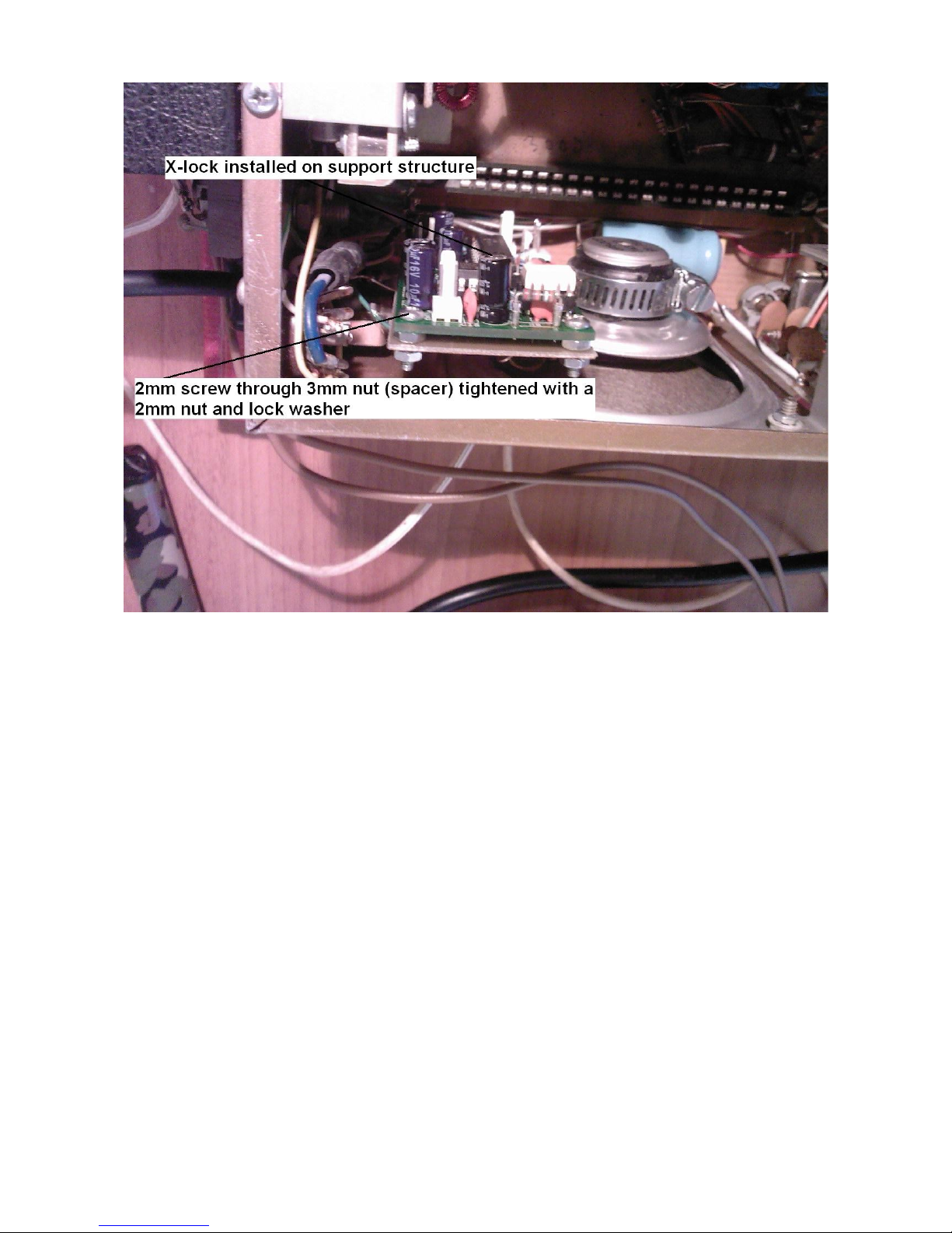
In my case, I chose to use a similar installation method that I had previously used for my Atlas rig
as seen in the following photo. First the x-lock board was installed on a general purpose Bakelite
board with four 2mm screws through its mounting holes and 3mm spacing nuts. A empty milk tin
can was then "sacrificed" to harvest 2 separate metal sheets that would connect the board to the 902
chassis.
The result is very stable and electrically / RF sound since the stabilizer is well grounded.
Question #2: How to interface the x-lock to the rig ?? The minimalist approach is to sample the RF
input from the Counter unit and wire the control voltage to the RIT line. Tried both and FAILED
miserably .... Most likely because the composite frequency presented at the counter input is
inversely related to the VFO frequency !! he he That way the stabilizer instead of stabilizing the
drift, made it worse!
Anyway, the minimalist approach as simple and innocent as it seems is neither and most of all does
not work.
Reluctantly then decided to try the real thing: getting my hands into the heart of the VFO ... And
indeed this proved to be both easier, less risky and much more tidier approach. Most of all it
WORKED beautifully!
First of all, one must remove the VFO assembly from the rig. Carefully done is straight forward. It
would be very useful, before removing the vfo, to align its analog dial according to the digital
frequency display, and be careful not to disturb the analog dial throughout the modification process.
This will be the indicator of the frequency difference imposed by the presence of the x-lock varicap
circuit (1n4004 and 1pF in series and parallel to TC801).
More on that later.
After extracting the VFO, remove its aluminum cover. You can identify the main tuning variable
cap, above it the vfo board and in the back the coil and a second variable cap TC801. This cap is
used to adjust the linearity of the analog scale in the vfo, and that is where the varicap circuit of the
stabilizer should be installed.
 Loading...