

Yaesu FT-227RB Instruction Manual
INSTRUCTION
MANUAL
FT-227RB
YAESU MUSEN CO ,LTD.
TOKYO JAPAN.
TABLE OF CONTENTS
(Page)
INTRODUCTION
1
SPECIFICATIONS
2
CONTROLS AND SWITCHES
3
REAR APRON
5
INSTALLATION
7
OPERATION
9
BLOCK DIAGRAM
11
THEORY OF OPERATION
12
MAINTENANCE AND ALIGNMENT
19
PARTS LIST
26

Ato
FT-227RB SCANNING MEMORIZER
2 METER FM TRANSCEIVER
The FT-227RB is a PLL synthesized FM transceiver, designed to provide high performance for
the discriminating 2 meter operator.
Channel selection is by means of a photo-interrupter scheme, providing selection of as many as
800 PLL channels between 144 and 148 MHz.
This optical coupling system eliminates noisy, unreliable rotary switches used in other makes of
equipment. Digital display of the last four digits
of the operating frequency is provided.
A memory circuit allows storage and recall of two
simplex and four repeater channels, with the press
of a switch. The memorized frequency may be
held when the power switch is turned off, via the
backup circuitry.
For repeater operation, ± 600 kHz split is provided,
and auxiliary splits may be programmed using the
memory system. Tone burst generation is provided,
and a subaudible tone squelch (CTCSS) encoder/
decoder is an available option for your FT-227RB.
Superb operating convenience is provided by the
PLL scanner, allowing up/down scanning control
from the microphone, without rotation of the
main tuning dial..
Your FT-227RB, represents the latest developments in solid-state technology. With proper care,
and if the directions to follow are observed without fail, your FT-227RB. will provide many years
of trouble-free operation. The owner is encouraged
to read this manual in its entirety, so as to become
better acquainted with the exciting new FT-227RB,
the latest development from the hams at YAESU.
1
SPECIFICATIONS
GENERAL
Frequency Converage
144
to 148
MHz
Number of Channels
800 channels
Speaker
Internal 3" dynamic speaker with provision
for connecting an external 8 ohm dynamic
speaker.
Microphone
Dynamic push-to-talk microphone with retractable coiled cord. Impedance is 600
ohms.
Deviation
±5 kHz.
Audio Response
+1,
—3 dB of 6 dB/Octave pre-emphasis
characteristic from 300 to 2500 Hz.
Spurious Emissions
60 dB below carrier minimum
Tone Burst.
Nominally one second at 1800 H
Repeater Split.
±600
kHz or any frequency in 5 kHz
increments
Power Requirement
RECEIVER
13.8 Volts DC, ±10%.
Current Consumption
0.5 Amps Receive.
2.5 Amps Transmit.
Metering
Illuminated front panel meter indicates
relative received signal strength and transmitter power output.
Type
Double conversion super-heterodyne
Intermediate Frequency
10.7 MHz
first IF; 455 kHz second IF
Sensitivity
0'.3 µV for 20 dB quieting.
Selectivity
Dimensions
±6
kHz at 6 dB: ±12 kHz at 60 dB
180 (W) x 60
(H)
x 220 (D) mm
Audio Output
Weight
1.5 Watts at 8 ohms
2.7 kg.
TRANSMITTER
RF Output
10
Watts into 50 ohm load at 13.8 Volts DC
Frequency Stability
±0.002%.
Modulation
F3.
SPECIFICATIONS SUBJECT TO CHANGE WITHOUT NOTICE
2
CD ® io ©
'0
13
CD ©
®
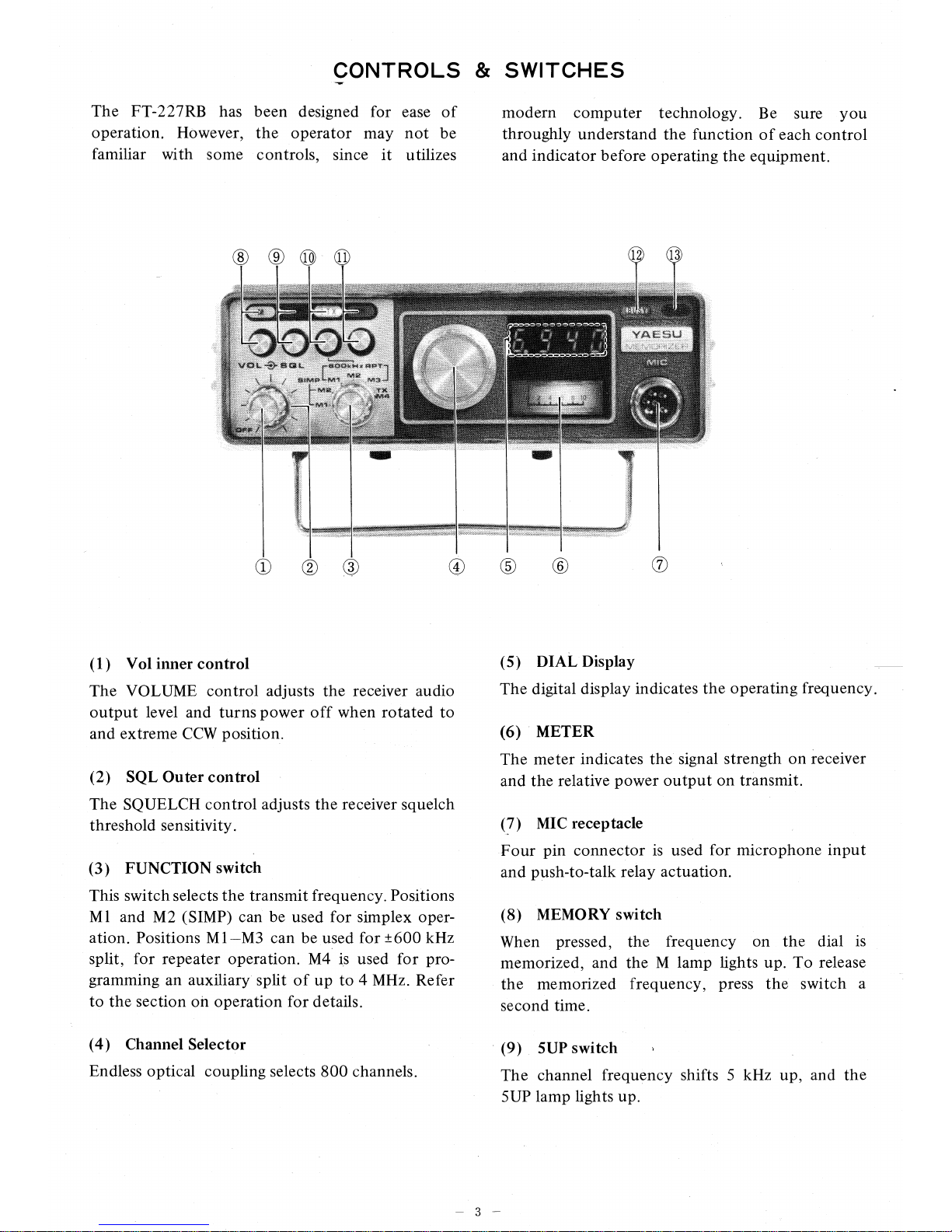
CONTROLS & SWITCHES
-
VW
The FT-227RB has been designed for ease of
modern computer technology. Be sure you
operation. However, the operator may not be
throughly understand the function of each control
familiar with some controls, since it utilizes
and indicator before operating the equipment.
(1)
Vol inner control
The VOLUME control adjusts the receiver audio
output level and turns power off when rotated to
and extreme CCW position.
(2)
SQL Outer control
The SQUELCH control adjusts the receiver squelch
threshold sensitivity.
(3)
FUNCTION switch
This switch selects the transmit frequency. Positions
M l and M2 (SIMP) can be used for simplex operation. Positions Ml—M3 can be used for ±600 kHz
split, for repeater operation. M4 is used for programming an auxiliary split of up to 4 MHz. Refer
to the section on operation for details.
(4)
Channel Selector
Endless optical coupling selects 800 channels.
(5)
DIAL Display
The digital display indicates the operating frequency.
(6) METER
The meter indicates the signal strength on receiver
and the relative power output on transmit.
(7)
MIC receptacle
Four pin connector is used for microphone input
and push-to-talk relay actuation.
(8)
MEMORY switch
When pressed, the frequency on the dial is
memorized, and the M lamp lights up. To release
the memorized frequency, press the switch a
second time.
(9)
5UP switch
The channel frequency shifts 5 kHz up, and the
5UP lamp lights up.
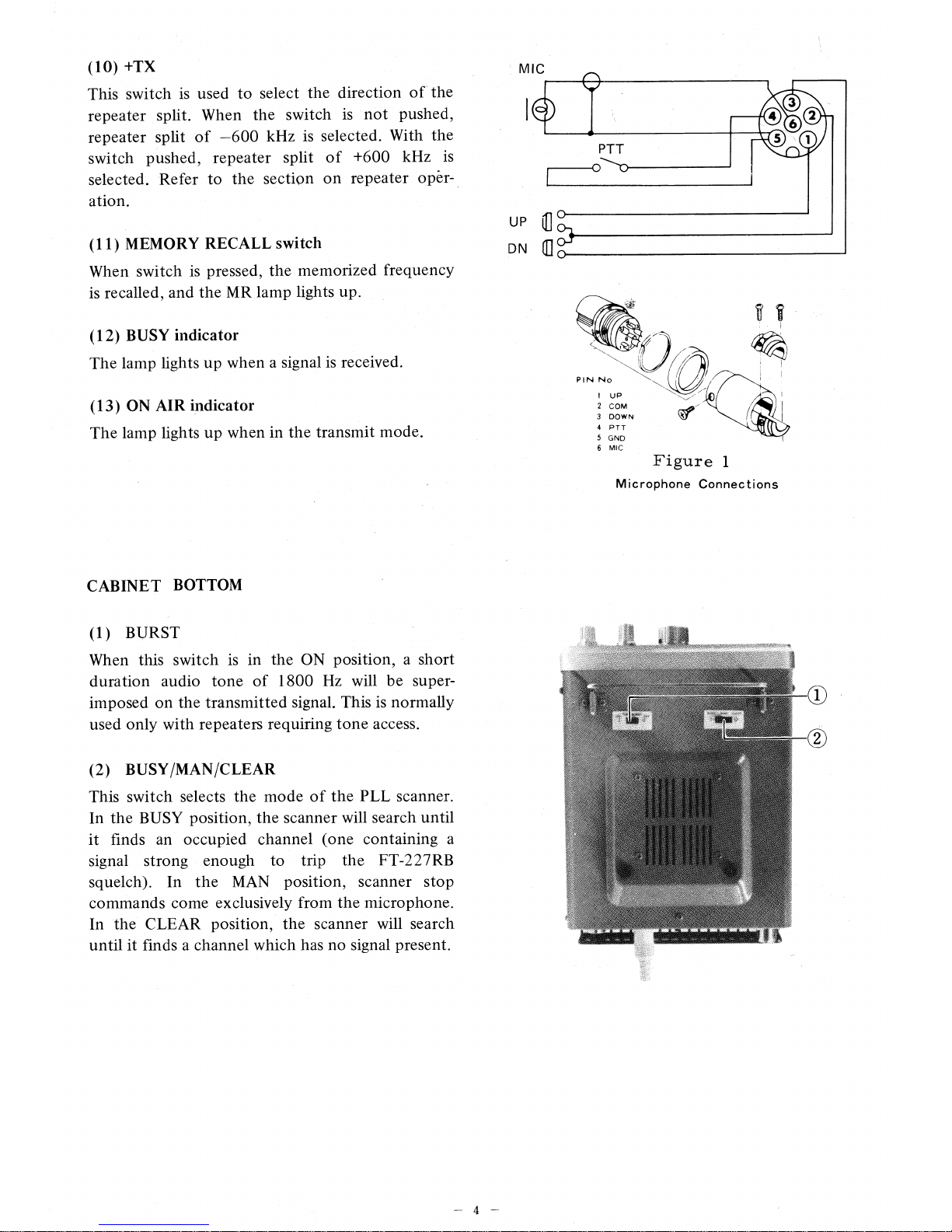
MIC
le
PTT
UP
C
DN
111
0
PIN No
1 UP
2 COM
3 DOWN
4 PTT
5 GND
6 MIC
(10)
+TX
This switch is used to select the direction of the
repeater split. When the switch is not pushed,
repeater split of —600 kHz is selected. With the
switch pushed, repeater split of +600 kHz is
selected. Refer to the section on repeater operation.
(11)
MEMORY RECALL switch
When switch is pressed, the memorized frequency
is recalled, and the MR lamp lights up.
(12)
BUSY indicator
The lamp lights up when a signal is received.
(13)
ON AIR indicator
The lamp lights up when in the transmit mode.
Figure
1
Microphone Connections
CABINET BOTTOM
(1)
BURST
When this switch is in the ON position, a short
duration audio tone of 1800 Hz will be super-
imposed on the transmitted signal. This is normally
used only with repeaters requiring tone access.
(2)
BUSY/MAN/CLEAR
This switch selects the mode of the PLL scanner.
In the BUSY position, the scanner will search until
it finds an occupied channel (one containing a
signal strong enough to trip the FT-227R13
squelch). In the MAN position, scanner stop
commands come exclusively from the microphone.
In the CLEAR position, the scanner will search
until it finds a channel which has no signal present.
NUS
MORIZE
FCC ECE1VER DAlrA
,;wFT;h2274:11
h
plies
u Part
date
Manuf
ctute
VHF FM IRAN
FT-227R8
SERML NO
M0300 7
Vgtallafar..„
O
CD CD CD
O
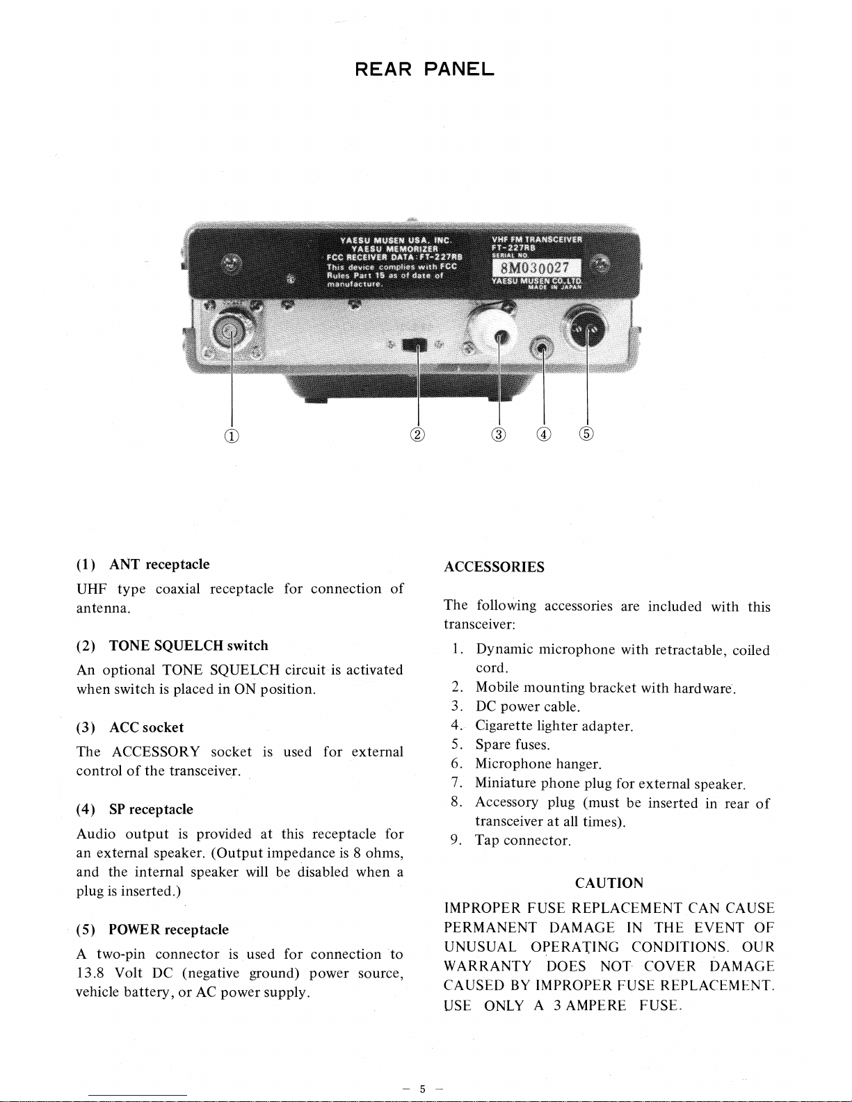
REAR PANEL
(1)
ANT receptacle
UHF type coaxial receptacle for connection of
antenna.
(2)
TONE SQUELCH switch
An optional TONE SQUELCH circuit is activated
when switch is placed in ON position.
(3)
ACC socket
The ACCESSORY socket is used for external
control of the transceiver.
(4)
SP receptacle
Audio output is provided at this receptacle for
an external speaker. (Output impedance is 8 ohms,
and the internal speaker will be disabled when a
plug is inserted.)
(5)
POWER receptacle
A two-pin connector is used for connection to
13.8 Volt DC (negative ground) power source,
vehicle battery, or AC power supply.
ACCESSORIES
The following accessories are included with this
transceiver:
1.
Dynamic microphone with retractable, coiled
cord.
2.
Mobile mounting bracket with hardware.
3.
DC power cable.
4.
Cigarette lighter adapter.
5.
Spare fuses.
6.
Microphone hanger.
7.
Miniature phone plug for external speaker.
8.
Accessory plug (must be inserted in rear of
transceiver at all times).
9.
Tap connector.
CAUTION
IMPROPER FUSE REPLACEMENT CAN CAUSE
PERMANENT DAMAGE IN THE EVENT OF
UNUSUAL OPERATING CONDITIONS. OUR
WARRANTY DOES NOT COVER DAMAGE
CAUSED BY IMPROPER FUSE REPLACEMENT.
USE ONLY A 3 AMPERE FUSE.
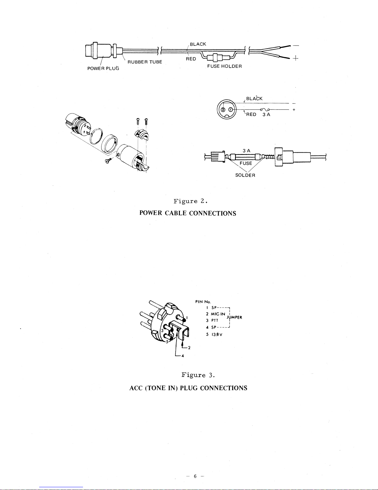
BLACK
1
i
RED
RUBBER TUBE
POWER PLUS
FUSE HOLDER
FUSE
SOLDER
3A
vcca
BLACK
Cr\.0
RED 3 A
Figure 2
.
POWER CABLE CONNECTIONS
PIN No.
I
2 MIC IN I
3 PTT
JUMPER
4 SP5 I3.8V
4
Figure 3.
ACC (TONE IN) PLUG CONNECTIONS
6
INSTALLATION
The FT-227RB transceiver is designed primarily
for mobile service, requiring only an antenna and
13.8 volt DC power source for operation. The
transceiver has been pre-tuned at the factory, and
requires no further adjustment for normal operation into a 50 ohm load.
Under no circumstances should the power cable
ever be connected to AC power. OUR WARRANTY DOES NOT COVER DAMAGE CAUSED
BY APPLICATION OF AC POWER TO THE
POWER JACK ON THE REAR APRON OF THE
TRANSCEIVER.
ANTENNA CONSIDERATIONS
In antenna installations, it is desirable that the
antenna be located as high and in the clear as
possible. In addition, be certain that the SWR on
the feedline is less than 1.5 : 1. A higher SWR may
cause a reduction in power output, because of the
protective circuitry incorporated in design. As well,
high SWR will increase the feedline losses.
In all installations, do not economize on coaxial
cable. For mobile applications, in which the feed-
line length is 20 feet or less, type RG-58A/U cable
is satisfactory, and the foam types are preferred,
because of their lower loss. For base station
systems, type RG8A/U may be used for moderate
lengths; for very long cable installations, we recommend the use of type RG-17A/U, air-dielectric
"heliax" cable, or aluminum-jacketed "foamflex"
coax. Beware of "bargain" coax, as the shield
coverage may be very poor, and this can seriously
degrade system performance.
BASE STATION INSTALLATION
As base station, the FT-227RB requires a power
source of 13.8 volts DC at 2.5 amperes. A base
station stand is included with your transceiver,
for easy viewing.
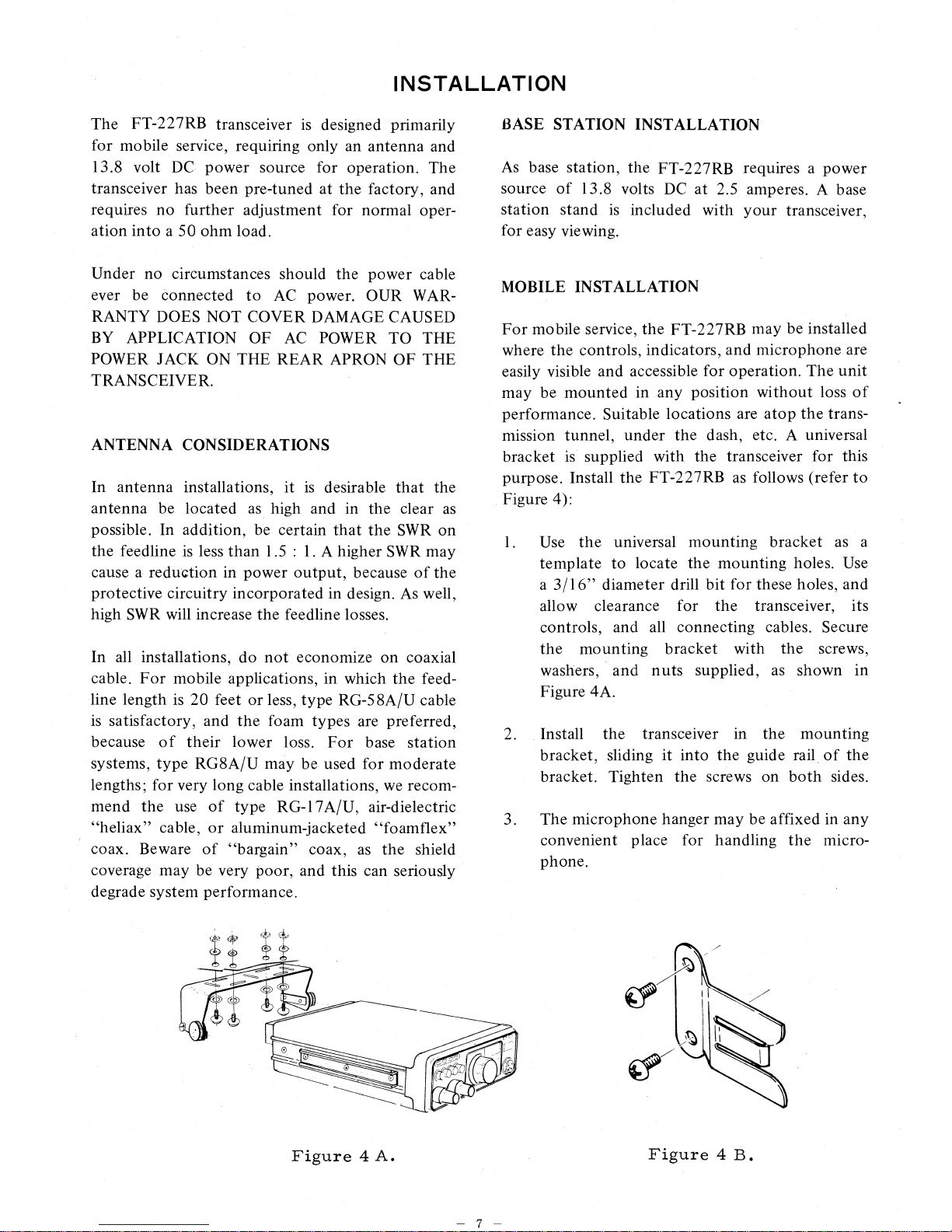
MOBILE INSTALLATION
For mobile service, the FT-227RB may be installed
where the controls, indicators, and microphone are
easily visible and accessible for operation. The unit
may be mounted in any position without loss of
performance. Suitable locations are atop the transmission tunnel, under the dash, etc. A universal
bracket is supplied with the transceiver for this
purpose. Install the FT-227RB as follows (refer to
Figure 4):
Use the universal mounting bracket as a
template to locate the mounting holes. Use
a 3/16" diameter drill bit for these holes, and
allow clearance for the transceiver, its
controls, and all connecting cables. Secure
the mounting bracket with the screws,
washers, and nuts supplied, as shown in
Figure 4A.
2.
Install the transceiver in the mounting
bracket, sliding it into the guide rail of the
bracket. Tighten the screws on both sides.
3.
The microphone hanger may be affixed in any
convenient place for handling the microphone.
Figure 4 A.
Figure 4 B.
 Loading...