

Yaesu FT-223 Operation
:;.ENERAL
THEOR Y OF
OPERA
TION
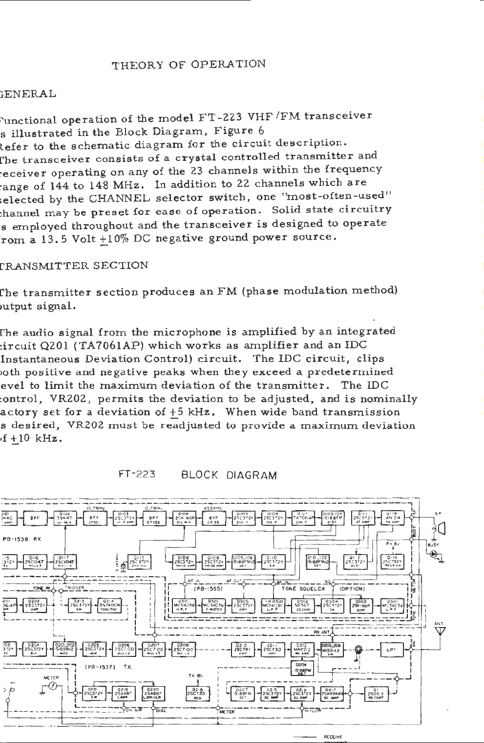
i'unctional
s
ìllustrated
lefer
['be
transceiver
:eceiver
:ange
;elected
:hannel
s
employed
rom a 13.5
CRANSMITTER
Che
transmitter
Jutput
Che
audio
:
ircuit
Instantaneous
lOth
positive
evel
to
:ontrol,
actory
s
desired,
•f + 10
to
the
operating
of
144
by
may
signal.
Q201
li.Init
VR202,
set
kHz.
operation
schematic
to
the
be
throughout
Volt
signal
(TA706IAP)
and
fora
VR202
in
the
Block
consista
on
148
MHz.
CHANNEL
preset
+lO
SECTION
section
from
Deviation
negative
the
maximum
permits
deviation
must
of
the
diagram
any
for
and
o/o
DC
the
produces
Contro!)
be
model
Diagram,
of a crystal
of
the
In
selector
ease
the
negative
microphone
which
peaks
deviation
the
of
readjusted
FT
for
23
addition
of
operation.
transceiver
an
works
circuìt.
when
deviation
+5kHz.
-223
Figure
the
circuit
controlled
channels
to
22
switch,
ground
FM
(phase
is
amplified
as
arnplifier
they
of
the
to
be
When
to
provide a maximum
VHF
IFM
transceiver
6
description.
transmitter
within
channels
one
Solid
is
designed
power
The
exceed a predetermined
transmitter.
adjusted,
wide
the
frequency
which
"most-often-used"
state
to
source.
modulation
by
an
and
an
IDC
circuit,
and
band
transmission
and
are
circuitry
operate
method)
integrated
IDC
clips
The
is
IDC
nominally
deviation
FT-
223
BLOCK
OIAGRAM
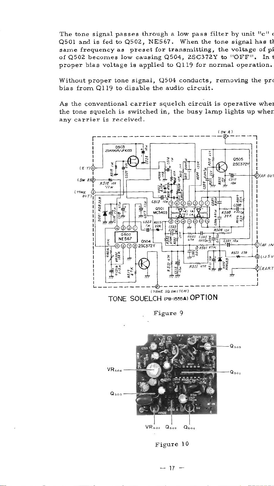
The
Downloaded
by
RadioManuai.EU
0501
same
of
0502
proper
tone
signa!
and
is
frequency
becomes
bias
passes
fed
to
as
voltage
0502,
low
through a low
NE567.
preset
for
causing
is
applied
pass
When
transmitting,
0504,
to
2SC372Y
0119
the
for
filter
tone
the
to 1'0FF".
normal
by
uni
signal
voltage
operation.
t 11c
has
of
In
11
c
t}
pi
t
Without
bias
from
As
the
the
tane
any
carrier
proper
0119
conventional
squelch
r--
l l
l l
l
l l
l l
tone
to
disable
is
is
received.
--------
signal,
carrier
switched
-
Q504
the
squelch
in,
audio
the
conducts,
circuit.
circuit
busy
------------
removing
is
lamp
l SIV A )
~
operative
lights
----ì
the
up
prc
wher
when
l
l
l
(
TOJYE.
TONE SQUELCH
Figure
---------------
SQ
S W l
ICH)
<Pe
-r555A) OPTION
9
.---
-~~
__
l
l
l
J
(
EA.R T
Figure
-
17
10
-
 Loading...