

Page 1
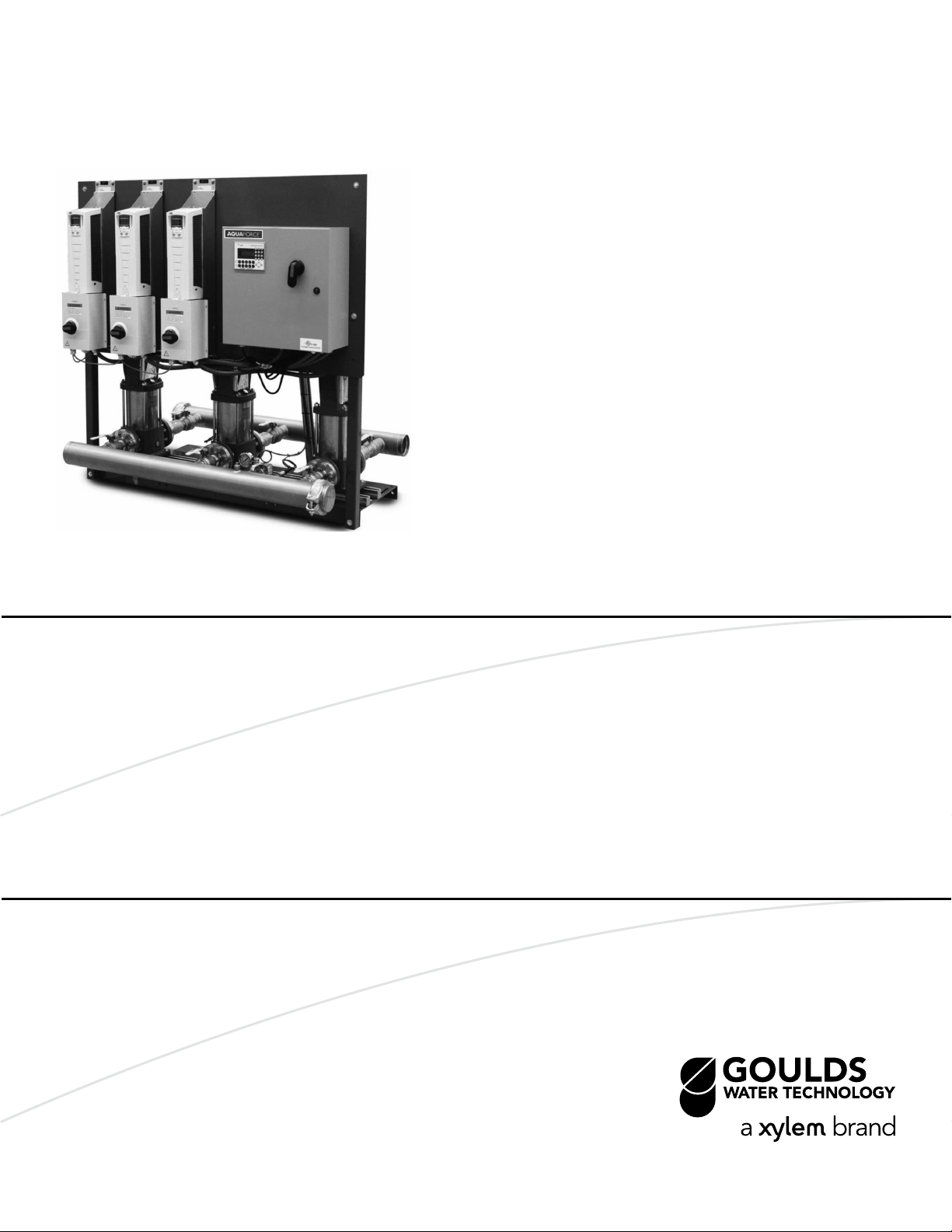
Mechanical
Installation,
Operation, and
Maintenance Manual
AquaForce Variable Speed Package
System
Page 2

Page 3

Table of Contents
Introduction and Safety.........................................................................................................................3
Introduction..........................................................................................................................................3
Safety.....................................................................................................................................................3
Safety terminology and symbols....................................................................................................3
Environmental safety........................................................................................................................4
Recycling guidelines........................................................................................................................5
User safety............................................................................................................................................5
Precautions during work..................................................................................................................5
Wash the skin and eyes....................................................................................................................6
Product warranty.................................................................................................................................6
Transportation and Storage..................................................................................................................8
Inspect the delivery.............................................................................................................................8
Inspect the package.........................................................................................................................8
Inspect the unit..................................................................................................................................8
Transportation guidelines..................................................................................................................8
Lifting methods.................................................................................................................................8
Storage guidelines..............................................................................................................................8
Storage location................................................................................................................................8
Table of Contents
Product Description.............................................................................................................................10
General description..........................................................................................................................10
Operational limits...........................................................................................................................10
Nameplate information....................................................................................................................10
Installation.............................................................................................................................................12
Field connections..............................................................................................................................12
Fastening............................................................................................................................................12
Earth (ground) connections.............................................................................................................12
Pump package location guidelines................................................................................................12
Foundation requirements................................................................................................................13
Level the base on a concrete foundation.......................................................................................13
Grout the baseplate..........................................................................................................................14
Piping checklist..................................................................................................................................14
Commissioning, Startup, Operation, and Shutdown......................................................................15
Preparation for startup.....................................................................................................................15
Prestartup checklist........................................................................................................................15
Final installation checks.................................................................................................................16
Final adjustments............................................................................................................................16
Pump station startup.........................................................................................................................17
Confirm the job site voltage..........................................................................................................17
Connect the storage tank..............................................................................................................17
Check for available suction water.................................................................................................17
Start the package............................................................................................................................18
Check the pump rotation..............................................................................................................18
Set the system operating pressure...............................................................................................18
Enter the setup menu.....................................................................................................................18
Test the package............................................................................................................................18
Maintenance.........................................................................................................................................19
Precautions.........................................................................................................................................19
AquaForce Variable Speed Package System Mechanical Installation, Operation, and Maintenance Manual 1
Page 4

Table of Contents
Monthly maintenance.......................................................................................................................19
Troubleshooting...................................................................................................................................21
Pump station troubleshooting.........................................................................................................21
The pump station does not power up.........................................................................................21
The station powers up, but the pumps do not run....................................................................21
The pumps run but do not build desired pressure....................................................................22
The pump station experiences excessive vibration...................................................................23
The pump station does not shut down and no water is used...................................................23
The pump station cycles or hunts erratically...............................................................................23
Technical Reference............................................................................................................................25
Pump station numbering system....................................................................................................25
Pump station with e-SV pumps.....................................................................................................25
Pump station with NPE pumps.....................................................................................................26
Pump station with SSH pumps......................................................................................................28
2 AquaForce Variable Speed Package System Mechanical Installation, Operation, and Maintenance Manual
Page 5
Introduction and Safety
Introduction
Purpose of this manual
The purpose of this manual is to provide necessary information for:
• Installation
• Operation
• Maintenance
CAUTION:
Read this manual carefully before installing and using the product. Improper use of the
product can cause personal injury and damage to property, and may void the warranty.
NOTICE:
Save this manual for future reference, and keep it readily available at the location of the
unit.
Introduction and Safety
Safety
WARNING:
• The operator must be aware of safety precautions to prevent physical injury.
• Any pressure-containing device can explode, rupture, or discharge its contents if it is
over-pressurized. Take all necessary measures to avoid over-pressurization.
• Operating, installing, or maintaining the unit in any way that is not covered in this manual
could cause death, serious personal injury, or damage to the equipment. This includes
any modification to the equipment or use of parts not provided by Xylem. If there is a
question regarding the intended use of the equipment, please contact a Xylem
representative before proceeding.
• Do not change the service application without the approval of an authorized Xylem
representative.
CAUTION:
You must observe the instructions contained in this manual. Failure to do so could result in
physical injury, damage, or delays.
Safety terminology and symbols
About safety messages
It is extremely important that you read, understand, and follow the safety messages and
regulations carefully before handling the product. They are published to help prevent
these hazards:
• Personal accidents and health problems
• Damage to the product
• Product malfunction
AquaForce Variable Speed Package System Mechanical Installation, Operation, and Maintenance Manual 3
Page 6
Introduction and Safety
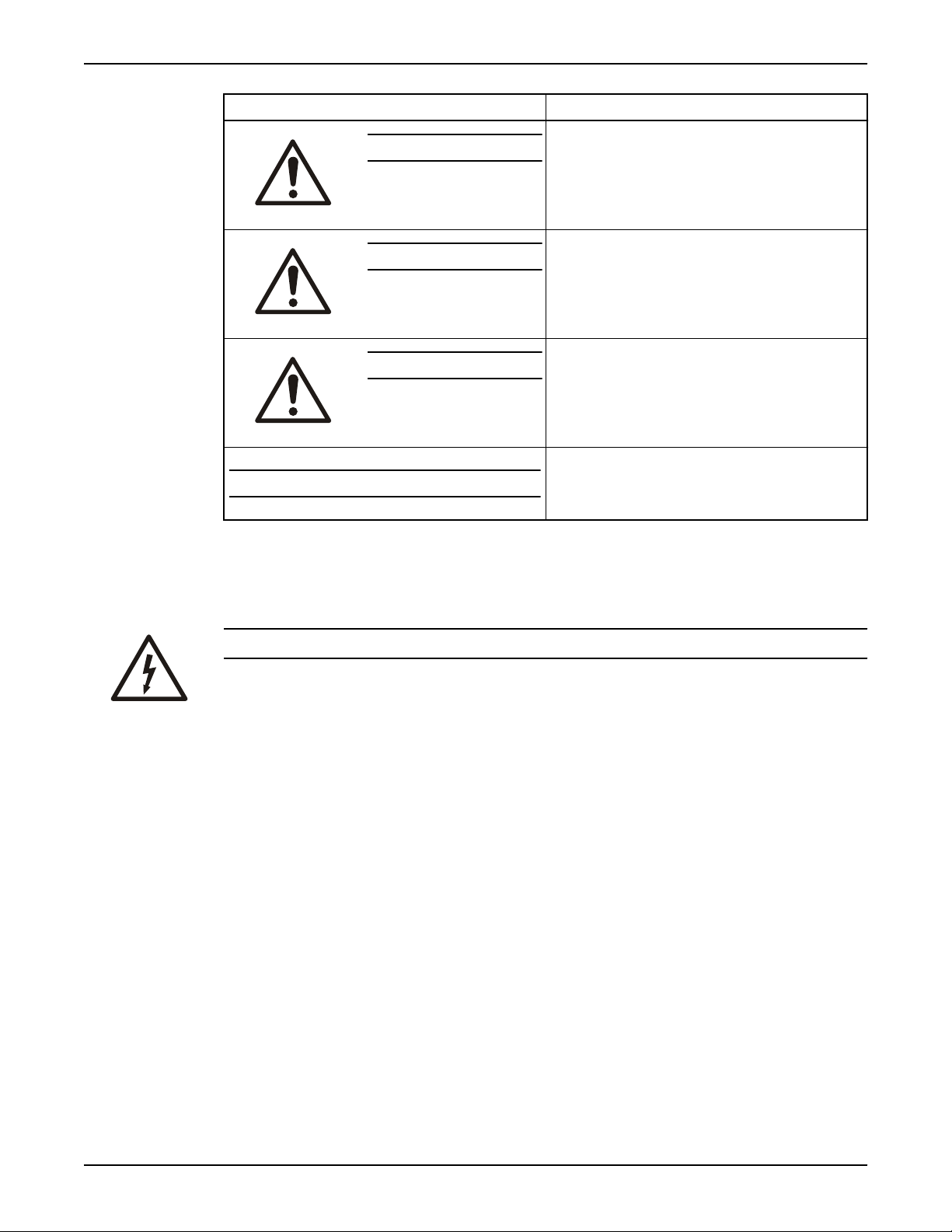
Hazard levels
Hazard level Indication
Hazard categories
DANGER:
WARNING:
CAUTION:
NOTICE:
Hazard categories can either fall under hazard levels or let specific symbols replace the
ordinary hazard level symbols.
Electrical hazards are indicated by the following specific symbol:
A hazardous situation which, if not avoided, will result in
death or serious injury
A hazardous situation which, if not avoided, could result
in death or serious injury
A hazardous situation which, if not avoided, could result
in minor or moderate injury
• A potential situation which, if not avoided, could
result in undesirable conditions
• A practice not related to personal injury
Electrical Hazard:
These are examples of other categories that can occur. They fall under the ordinary hazard
levels and may use complementing symbols:
• Crush hazard
• Cutting hazard
• Arc flash hazard
Environmental safety
The work area
Always keep the station clean.
Waste and emissions regulations
Observe these safety regulations regarding waste and emissions:
• Appropriately dispose of all waste.
• Handle and dispose of the processed liquid in compliance with applicable
environmental regulations.
• Clean up all spills in accordance with safety and environmental procedures.
• Report all environmental emissions to the appropriate authorities.
4 AquaForce Variable Speed Package System Mechanical Installation, Operation, and Maintenance Manual
Page 7

Electrical installation
Recycling guidelines
User safety
General safety rules
Introduction and Safety
WARNING:
Radiation Hazard. Do NOT send the product to Xylem if it has been exposed to any nuclear
radiation.
For electrical installation recycling requirements, consult your local electric utility.
Always follow local laws and regulations regarding recycling.
These safety rules apply:
• Always keep the work area clean.
• Pay attention to the risks presented by gas and vapors in the work area.
• Avoid all electrical dangers. Pay attention to the risks of electric shock or arc flash
hazards.
• Always bear in mind the risk of drowning, electrical accidents, and burn injuries.
Safety equipment
Use safety equipment according to the company regulations. Use this safety equipment
within the work area:
• Hard hat
• Safety goggles, preferably with side shields
• Protective shoes
• Protective gloves
• Gas mask
• Hearing protection
• First-aid kit
• Safety devices
Electrical connections
Electrical connections must be made by certified electricians in compliance with all
international, national, state, and local regulations. For more information about
requirements, see sections dealing specifically with electrical connections.
Precautions during work
NOTICE:
Never operate a unit unless safety devices are installed. Also see specific information
about safety devices in other chapters of this manual.
Observe these safety precautions when you work with the product or are in connection
with the product:
• Never work alone.
• Always wear protective clothing and hand protection.
• Stay clear of suspended loads.
• Always lift the product by its lifting device.
• Beware of the risk of a sudden start if the product is used with an automatic level
control.
• Beware of the starting jerk, which can be powerful.
AquaForce Variable Speed Package System Mechanical Installation, Operation, and Maintenance Manual 5
Page 8
Introduction and Safety
• Rinse the components in water after you disassemble the pump.
• Do not exceed the maximum working pressure of the pump.
• Do not open any vent or drain valve or remove any plugs while the system is
• Never operate a pump without a properly installed coupling guard.
Wash the skin and eyes
pressurized. Make sure that the pump is isolated from the system and that pressure is
relieved before you disassemble the pump, remove plugs, or disconnect piping.
Follow these procedures for chemicals or hazardous fluids that have come into contact
with your eyes or your skin:
Condition Action
Chemicals or hazardous
fluids in eyes
Chemicals or hazardous
fluids on skin
Product warranty
Coverage
Xylem undertakes to remedy defects in products from Xylem under these conditions:
• The faults are due to defects in design, materials, or workmanship.
• The faults are reported to an local sales and service representative within the warranty
period.
• The product is used only under the conditions described in this manual.
• The monitoring equipment incorporated in the product is correctly connected and in
use.
• All service and repair work is done by Xylem authorized personnel.
• Genuine Xylem parts are used.
• Only Ex-approved spare parts and accessories authorized by an EX-approved Xylem
representative are used in Ex-approved products.
1. Hold your eyelids apart forcibly with your fingers.
2. Rinse the eyes with eyewash or running water for at least 15 minutes.
3. Seek medical attention.
1. Remove contaminated clothing.
2. Wash the skin with soap and water for at least 1 minute.
3. Seek medical attention, if necessary.
Limitations
The warranty does not cover defects caused by these situations:
• Deficient maintenance
• Improper installation
• Modifications or changes to the product and installation made without consulting an
Xylem authorized representative
• Incorrectly executed repair work
• Normal wear and tear
Xylem assumes no liability for these situations:
• Bodily injuries
• Material damages
• Economic losses
6 AquaForce Variable Speed Package System Mechanical Installation, Operation, and Maintenance Manual
Page 9

Warranty claim
Introduction and Safety
Xylem products are high-quality products with expected reliable operation and long life.
However, should the need arise for a warranty claim, then contact your local sales and
service representative.
AquaForce Variable Speed Package System Mechanical Installation, Operation, and Maintenance Manual 7
Page 10
Transportation and Storage
Transportation and Storage
Inspect the delivery
Inspect the package
1. Inspect the package for damaged or missing items upon delivery.
2. Note any damaged or missing items on the receipt and freight bill.
3. File a claim with the shipping company if anything is out of order.
If the product has been picked up at a distributor, make a claim directly to the
distributor.
Inspect the unit
1. Remove packing materials from the product.
Dispose of all packing materials in accordance with local regulations.
2. Inspect the product to determine if any parts have been damaged or are missing.
3. If applicable, unfasten the product by removing any screws, bolts, or straps.
For your personal safety, be careful when you handle nails and straps.
4. Contact the local sales representative if there is any issue.
Transportation guidelines
Lifting methods
WARNING:
• Assembled units and their components are heavy. Failure to properly lift and support
this equipment can result in serious physical injury and/or equipment damage. Lift
equipment only at the specifically identified lifting points. Lifting devices such as
eyebolts, slings, and spreaders must be rated, selected, and used for the entire load
being lifted.
• Crush hazard. The unit and the components can be heavy. Use proper lifting methods
and wear steel-toed shoes at all times.
• Tip over hazard. Do not use component eyebolts to lift the pump station. The eyebolts
are only designed to lift the components to which they are attached.
• Do not attach sling ropes to the panel stand.
Storage guidelines
Storage location
The product must be stored in a covered and dry location free from heat, dirt, and
vibrations.
NOTICE:
• Protect the product against humidity, heat sources, and mechanical damage.
• Do not place heavy weights on the packed product.
8 AquaForce Variable Speed Package System Mechanical Installation, Operation, and Maintenance Manual
Page 11

Storage between use
Long-term storage
Transportation and Storage
Observe the following for long-term storage of a pump station.
• Insure system is drained of any water.
• Remove transducers to ensure that they do not freeze.
• System may be top-heavy, brace to keep from tipping.
If the unit is stored for more than 6 months, these requirements apply:
• Store in a covered and dry location.
• Store the unit free from heat, dirt, and vibrations.
• Rotate the pump shaft by hand several times at least every three months.
Treat bearings and machined surfaces so that they are well preserved. Refer to the drive
unit and coupling manufacturers for their long-term storage procedures.
For questions about possible long-term storage treatment services, please contact your
local sales and service representative.
AquaForce Variable Speed Package System Mechanical Installation, Operation, and Maintenance Manual 9
Page 12

Product Description
Product Description
General description
Description
A pump station is a pre-engineered and fabricated line of packaged booster systems that
provides:
• Energy efficiency
• System protection
• Hydraulic capability up to 1600 GPM
• Boost pressures up to 300 PSI
Intended applications
The pump station is intended for these applications:
• High rise buildings
• Industrial plants
• Municipal and rural water districts
• Agriculture / irrigation
• General water pressure boosting
Operational limits
Pressure
This table describes the pressure ratings for a pump station using the pump model shown
Pump system type Max. discharge pressure
NPE pumps 125 PSI
SSH Pumps 230 PSI
e-SV Pumps 300 PSI
Nameplate information
Important information for ordering
Every pump station has a nameplate that provides information about the pump station.
The pump station nameplate is located on the inside of the control enclosure door.
When ordering spare parts, be prepared to identify the nameplate information when
contacting the factory.
• Model
• Size
10 AquaForce Variable Speed Package System Mechanical Installation, Operation, and Maintenance Manual
Page 13

Date Code
Pump Boost
Discharge Pressure
Suction Pressure
Station Flow
Largest Motor HP
SCCR
System FLA
Station Voltage
Serial Number
Model Number
Applied Water Solutions
Dallas, Texas, U.S.A .
Customer Service 1.800.786.7480
Product Description
• Serial number
• Item numbers of the required parts.
Nameplate field Explanation
Model number The manufacturer's number to indicate the particular type of product which has been
acquired.
AquaForce Variable Speed Package System Mechanical Installation, Operation, and Maintenance Manual 11
Serial number A set of characters that uniquely identifies a single unit and can be used for
traceability and warranty purposes.
Station voltage The rated voltage at which the station has been designed for. Should match the
application site supply voltage.
System FLA The full-load-amperage at which the station can operate.
SCCR “Short-Circuit Current rating”. Represents the maximum level of short-circuit current
that a component or assembly can withstand.
Largest motor HP The rated HP for the largest pump in the system.
Station flow The designed duty point, in GPM, LPH, etc.
Suction pressure inlet The line pressure on the input side of the pump station.
Discharge pressure The line pressure on the output side of the pump station
Pump boost The difference between the input side of the pump station and the output side of the
pump station.
Date code Marking of products to indicate their date of manufacture.
Page 14

Installation
Installation
Field connections
Diagrams
Actual equipment manufacturers/models installed are system specific. Refer to specific
manufacturer Installation, Operation, and Maintenance manuals for details unique to each
component. The pump instruction manual is supplied with the system.
Review the wiring diagrams and dimensional drawings before you install and operate the
unit.
Electrical precautions
WARNING:
Electrical shock hazard. The electrical supply must match the control panel nameplate
specification. Incorrect voltage can cause a fire, which damages the electrical components
and voids the warranty. Failure to follow these instructions could result in serious personal
injury or death, or property damage.
NOTICE:
Electrical connections must be made by certified electricians in compliance with all
international, national, state, and local rules.
Fastening
WARNING:
• Only use fasteners of the proper size and material.
• Replace all corroded fasteners.
• Make sure that all fasteners are properly tightened and that there are no missing
fasteners.
Earth (ground) connections
WARNING:
Electrical shock hazard. Conduit grounds are not adequate. You must attach a separate
earth (ground) wire to the earth (ground) lug provided in the enclosure in order to avoid
potential safety hazards. Failure to follow these instructions can result in serious personal
injury, death, or property damage.
A grounding terminal is provided for a dedicated earth (ground) wire connection. You
must follow all provisions of the National Electrical Code and local codes.
Pump package location guidelines
WARNING:
Assembled units and their components are heavy. Failure to properly lift and support this
equipment can result in serious physical injury and/or equipment damage. Lift equipment
only at the specifically identified lifting points. Lifting devices such as eyebolts, slings, and
spreaders must be rated, selected, and used for the entire load being lifted.
12 AquaForce Variable Speed Package System Mechanical Installation, Operation, and Maintenance Manual
Page 15

Guideline Explanation/comment
Make sure that the space around the pump package is
sufficient.
If you require lifting equipment such as a hoist or tackle,
make sure that there is enough space above the pump
package.
Protect the unit from weather and water damage due to
rain, flooding, and freezing temperatures.
Do not install and operate the equipment in closed
systems unless the system is constructed with properlysized safety and control devices.
This facilitates ventilation, inspection, maintenance, and
service.
This makes it easier to properly use the lifting equipment
and safely remove and relocate the components to a safe
location.
This is applicable if nothing else is specified.
Acceptable devices:
• Pressure relief valves
• Compression tanks
• Pressure controls
• Temperature controls
• Flow controls
If the system does not include these devices, consult the
engineer or architect in charge before you operate the
pump.
Installation
Take into consideration the occurrence of abnormal noise
and vibration.
Foundation requirements
WARNING:
Electrical shock hazard. An electrical conduit installed below the surface may require a
corrosion-resistant protective coating in order to prevent conduit corrosion and electrical
shock. Failure to follow these instructions can result in serious personal injury, death, or
property damage.
Requirements
• The foundation must be able to absorb any type of vibration and form a permanent,
rigid support for the unit.
• The foundation must weigh at least 2-1/2 times the weight of the pump unit.
• Provide a flat, substantial concrete foundation in order to prevent strain and distortion
when you tighten the foundation bolts.
• Sleeve-type and J-type foundation bolts are most commonly used. Both designs allow
movement for the final bolt adjustment.
• Tie the concrete pad in with the finished floor.
Level the base on a concrete foundation
1. Place the pump package on its concrete foundation.
2. Place 1.00 in./(25.40 mm) thick steel shims or wedges on both sides of each anchor
bolt in order to support the pump package.
Make sure you also place the shims or wedges midway between the bolts.
This also provides a means of leveling the base.
The best pump location for noise and vibration
absorption is on a concrete floor with subsoil underneath.
AquaForce Variable Speed Package System Mechanical Installation, Operation, and Maintenance Manual 13
Page 16

Installation
Grout the baseplate
Required equipment:
• Cleaners: Do not use an oil-based cleaner because the grout will not bond to it. See
the instructions provided by the grout manufacturer.
• Grout: Non-shrink grout is required.
1. Clean all the areas of the baseplate that will come into contact with the grout.
2. Build a dam around the foundation.
3. Thoroughly wet the foundation that will come into contact with the grout.
4. Pour grout into the baseplate up to top of the base rails.
To hold wedges or shims in place, allow the grout to flow around them.
Follow grout manufacturer's instructions for removing air pockets from grout during
pour.
5. Allow the grout to set.
The grout needs to set for at least 48 hours. Follow any additional instructions from the
grout manufacturer.
6. Tighten the foundation bolts.
Piping checklist
WARNING:
• The heating of water and other fluids causes volumetric expansion. The associated forces
can cause the failure of system components and the release of high-temperature fluids.
In order to prevent this, install properly sized and located pressure-relief valves. Failure
to follow these instructions can result in serious personal injury or death, or property
damage.
• Avoid serious personal injury and property damage. Make sure that the flange bolts are
adequately torqued.
• Never force piping to make a connection with a pump.
Check Explanation/comment Checked
Check that the suction and discharge pipes are
supported independently by use of pipe hangers near
the pump station.
Check that there is a strong, rigid support for the
suction and discharge lines.
Check that the suction or discharge lines are not
forced into position.
Check that fittings for absorbing expansion are
installed in the system when considerable
temperature changes are expected.
This eliminates pipe strain on the pump
station.
As a rule, ordinary wire or band hangers are not
adequate to maintain proper alignment.
Component failure will result if suction or
discharge lines are forced into position.
This helps to avoid strain on the pump.
Check that you have a foot valve of equal or greater
area than the pump suction piping when you use an
open system with a suction lift.
14 AquaForce Variable Speed Package System Mechanical Installation, Operation, and Maintenance Manual
Prevent clogging by using a strainer at the
suction inlet next to the foot valve. Make sure
that the strainer has an area three times that of
the suction pipe with a mesh hole diameter of
no less than 0.25 in. (0.64 cm).
Page 17

Commissioning, Startup, Operation, and Shutdown
Commissioning, Startup, Operation,
and Shutdown
Preparation for startup
DANGER:
Electrical hazard sufficient to kill. Always disconnect and lock out the power before you
service the unit.
WARNING:
Explosion hazard. Do not short battery terminals together or damage the battery.
WARNING:
• Failure to follow these precautions before you start the unit will lead to serious personal
injury and equipment failure.
• Do not operate the pump below the minimum rated flows or with the suction or
discharge valves closed. These conditions can create an explosive hazard due to
vaporization of pumped fluid and can quickly lead to pump failure and physical injury.
• Always disconnect and lock out power to the driver before you perform any installation
or maintenance tasks. Failure to disconnect and lock out driver power will result in
serious physical injury.
• Operating the pump in reverse rotation can result in the contact of metal parts, heat
generation, and breach of containment.
NOTICE:
• Verify the driver settings before you start any pump.
You must follow these precautions before you start the pump:
• Flush and clear the system thoroughly to remove dirt or debris in the pipe system in
• Verify controller settings match site conditions and motor nameplate data before
Prestartup checklist
CAUTION:
Risk of leaks or flooding. Make sure to reinstall the drain plugs properly. Check all joints for
tightness and flange bolts for the proper torque.
Checks Checked
Check that the pump is properly aligned. Refer to these manual numbers for more
information:
order to prevent premature failure at initial startup.
starting station.
• eSV pumps = IM228
• NPE pumps = IM013
• SSH pumps = IM084
AquaForce Variable Speed Package System Mechanical Installation, Operation, and Maintenance Manual 15
Page 18

Commissioning, Startup, Operation, and Shutdown
Checks Checked
Check that the drain plugs are installed before filling system.
Inspect all piping joints for tightness.
Joints can become loose during transit due to vibration and shock.
Check all flanged joints for the proper torque.
Check that the system is full of liquid.
Check that all high points in the piping system are vented in order to remove trapped
air.
Check that all pumps and drivers are properly lubricated.
Check that the piping is clean and has been flushed.
Final installation checks
Installation checklist
CAUTION:
Serious damage to the pump may result if it is started dry. Make sure that the pump is
completely filled with liquid before it is started.
Check Checked
Check that the unit base is properly leveled, grouted, and secured.
Check that all lubrication points are properly lubricated.
Check that the outlet side of the high-temperature relief valve assembly (if option is
purchased) is connected to the drain with tubing or pipe sized 1/2 in. or greater.
Check that the shut-off valves to the transmitters are open.
Check that the pump and motor shafts are properly aligned.
Check that the pump rotation is correct.
Check that the piping is properly supported. This prevents strains on the unit.
Final adjustments
Make the final adjustments on these adjustable devices in order to match the exact system
requirements.
Thermal relief valve
An optional thermal relief valve is installed on the pump discharge in order to prevent
potentially dangerous thermal pressure buildup. The valve automatically opens on a
temperature increase and closes on a temperature decrease. This valve acts as a safety
device; do not remove or plug it. It is factory set to open and discharge when the water
temperature in the discharge header reaches between 125°F to 135°F (51°C to 57°C).
Make sure that the 1/2 in. NPT opening of this valve assembly is piped to a floor drain in
accordance with local codes.
After long periods of operation, the valve seat and disc can become worn or pitted. This
allows leaks through the valve in the closed position. You can replace internal parts, if
desired.
Low suction pressure switch (optional)
Adjust the setting to 10 psi below the rated suction pressure.
16 AquaForce Variable Speed Package System Mechanical Installation, Operation, and Maintenance Manual
Page 19

Pump station startup
Confirm the job site voltage
1. Check these items before you apply power or close the disconnect:
a) Check all of the power wiring connections and secure them as required.
b) Confirm with the owner/installing contractor if there are plans for any required
building automation or remote connections.
c) Inspect and/or install any customer remote terminations.
2. Make note of the design data supplied on the data label. The label is located on the
inside of the control panel door.
3. Use a volt meter to check the voltage on the incoming power terminals at the
disconnect.
4. Compare the voltage to the data on the nameplate.
Connect the storage tank
DANGER:
Explosion hazard. Prevent tank explosion. Do not install the tank when the system shut-off
pressure exceeds the tank pressure rating.
Commissioning, Startup, Operation, and Shutdown
DANGER:
Explosion hazard. Prevent tank explosion. Install a pressure relief valve on the tank inlet
with a set point no greater than tank rating.
1. Precharge the storage tank before you connect it to the system.
The air precharge needs to be 5 to 10 psi less than the system operating pressure.
2. If the storage tank has already been installed and not precharged, then disconnect the
system piping from the tank and equalize it to atmospheric pressure. If an isolation
valve and drain are provided, then use them.
3. Apply air pressure to the tank through the air charging valve and pressurize to field
conditions.
This needs to be equal to the NFSD restart pressure of 5 to 10 psi below the operating
pressure.
4. Reconnect the tank to the system piping. Tank should be installed on the discharge
side of the system.
Check for available suction water
1. Open all supply, discharge, and pump isolation valves. Also open any other package
valves.
2. Close the bypass valve if it is installed in the piping by others.
3. Inspect the capillary tubing from the pump discharge to the suction header:
a) Open the petcocks that feed the tubing.
b) Make sure that the plastic tubing does not touch any metal surface. Protect the
tubing with insulation in order to prevent abrasion where it can possibly touch
metal.
4. Open a faucet in order to create a demand for water on the system pressure piping.
5. Observe the suction pressure and confirm that it is equal to or greater than the suction
pressure listed on the nameplate. System is designed for a specific suction pressure.
Deviation results in degraded system performance. Contact factory if suction pressure
varies from design specifications.
AquaForce Variable Speed Package System Mechanical Installation, Operation, and Maintenance Manual 17
Page 20

Commissioning, Startup, Operation, and Shutdown
Start the package
1. Close the disconnect in order to apply power to the package.
2. Turn the panel switch to the local position.
3. Watch the screen as the boot-up progresses and note the serial number of the unit.
This is the password that you use for the setup menu.
4. If the unit starts, press the Stop button in order to stop the unit.
Check the pump rotation
1. Select the hand mode on the controller.
2. Enable the pump with the blinking green light.
Do not select any of the other pumps (no green light).
3. Press the start button and spin the first pump.
4. Immediately press the Stop button.
5. Observe the spinning shaft for rotation.
6. Repeat steps 1 through 5 for each pump.
7. If all pumps run backwards, reverse the two leads of the incoming power.
8. If only one of the pumps run backwards, reverse the two leads on the pump motors
that are incorrect.
Set the system operating pressure
1. Open a faucet or some other demand for water from the discharge of the package.
This can be anywhere in the building being served by the package.
2. In hand, run one pump.
3. Repeat these steps for each pump in the package. Run only one pump at a time.
Enter the setup menu
1. For each pump, confirm the settings entered for the pump motor data.
2. Review all settings for the compatibility with the installed application.
3. Make sure that these settings are in place:
• Auto alt. prd. - 24 or 168 hours
• Forced destage timer - 10 to 15 minutes
• NFSD restart psi - Enter a value 5 to 10 psi less than the site-adjusted discharge
• NSFD minimum run timer - 5 minutes
• NFSD test PR timer - 20 seconds
4. Adjust any other settings in order to meet the needs of your system.
Test the package
1. Exit the setup menu.
2. Stop the package.
3. Press the Auto key and then Start.
4. Observe the pressures and temperatures for normal operation.
5. Press the Alternation key and observe the operation of each pump.
6. Close the running water faucet.
It is assumed that no demand for water is required. For example, no flow.
7. Observe the No Flow Shutdown sequence. All minimum run timers must elapse for this
sequence to occur.
8. Demand water from the system and observe the restart of the package.
pressure
If you encountered no problems, then you are done.
18 AquaForce Variable Speed Package System Mechanical Installation, Operation, and Maintenance Manual
Page 21

Maintenance
Precautions
DANGER:
Electrical hazard sufficient to kill. Always disconnect and lock out the power before you
service the unit.
WARNING:
• This manual clearly identifies accepted methods for disassembling units. These methods
must be adhered to. Trapped liquid can rapidly expand and result in a violent explosion
and injury. Never apply heat to impellers, propellers, or their retaining devices to aid in
their removal.
• Make sure that each pump and the package are isolated from the system and that
pressure is relieved before you disassemble the pump, remove plugs, open vent or drain
valves, or disconnect the package piping.
• Always disconnect and lock out power to the package and the driver before you perform
any installation or maintenance tasks. Failure to disconnect and lock out driver power will
result in serious physical injury.
• Crush hazard. The unit and the components can be heavy. Use proper lifting methods
and wear steel-toed shoes at all times.
• Rotating shaft. Make sure that the packing adjustment is performed by qualified
personnel only.
Maintenance
CAUTION:
Equipment damage hazard. Silt buildup is a sign of problems with the wet well and/or
intake screen. Failure to follow these instructions indicates a potentially hazardous
situation, which, if not avoided, may result in property damage.
Monthly maintenance
Control panel checks
• Verify that all of the operator interface keys and LEDS operate properly (see controller
manual).
• Review the station operation, fault history, and data log for station operation.
• Verify that all surge devices are visually sound, where applicable.
• Check the surge device for the station which is mounted on the back of the control
panel.
• Black soot on or around the device indicates that it has taken a surge and needs to
be replaced.
AquaForce Variable Speed Package System Mechanical Installation, Operation, and Maintenance Manual 19
Page 22

Maintenance
Motor lubrication checks
• For grease-filled bearings, make sure that grease is not all over the inside of the motor
and in the bottom of the motor. This could be a sign of overfilling. Refer to the
lubrication instructions from the motor manufacturer.
Close-coupled pumps
• For a horizontal pump, verify that the mechanical seal is not leaking between the pump
and the motor.
Sound and visual checks of the whole station
• Listen for any odd sounds that rub or grind, electrical arcing, and check for anything
that is binding or unusual. These conditions can indicate a serious problem.
Note that there is going to be some harmonic vibration with the pumps and motor.
Listen for excessive vibration or noise as this requires immediate service. Do not
operate the pump if there is excessive vibration.
• Confirm that the building cooling and ventilation systems are operating and clear of all
obstructions. The maximum operating range for equipment is 104°F (40°C).
• Verify that water, grease, oil, and hardware are not leaking or loose on the pump
station.
Station skid
• Visually inspect for leaks in the station piping, valves, and other components.
• Visually inspect the piping and skid for any stress cracks in the welds.
• Visually inspect the station for loose or damaged paint or areas of rust.
20 AquaForce Variable Speed Package System Mechanical Installation, Operation, and Maintenance Manual
Page 23

Troubleshooting
Pump station troubleshooting
DANGER:
• Personal injury hazard. Troubleshooting a live control panel exposes personnel to
hazardous voltages. Electrical troubleshooting must be done by a qualified electrician.
Failure to follow these instructions will result in serious personal injury, death, and/or
property damage.
• Electrical hazard sufficient to kill. Always disconnect and lock out the power before you
service the unit.
WARNING:
Electrical connections must be made by certified electricians in compliance with all
international, national, state, and local rules.
Note that some troubleshooting procedures apply to only constant speed systems or only
variable speed systems.
Use these Installation, Operation, and Maintenance manuals for more information:
• e-SV pumps = IM228
• NPE pumps = IM013
• SSH pumps = IM084
Troubleshooting
The pump station does not power up
Cause Remedy
The site voltage does not match the pump station
voltage.
Line-to-line voltage is not balanced. Check incoming voltage and amperage. Line-to-line
The power fuses are blown or breakers are tripped. Check power fuses and breakers. Breakers are shipped in
The pump station is not properly grounded (earthed). Check that proper grounding (earthing) techniques have
There is a fault. Check for fault codes or fault lights on the PLC. Correct
The station powers up, but the pumps do not run
Cause Remedy
Pumps are not enabled. Check the PLC to make sure that the pumps are enabled.
The desired pressure is satisfied. Check to see if the desired pressure is satisfied. If the
There is a fault. Check for fault codes or fault lights on the PLC. Correct
The motor is tripped. Check for a tripped motor thermal protector. Allow motor
Make sure that the site voltage matches the pump station
design voltage.
voltage should be balanced. Line-to-ground voltage
should also be balanced.
the OFF position. Replace blown fuses.
been used for the pump station.
the fault.
Check for faults. Correct any faults.
actual pressure is greater than the set point pressure,
then the pumps are automatically stopped.
the fault.
to cool, and then reset the thermal protector.
AquaForce Variable Speed Package System Mechanical Installation, Operation, and Maintenance Manual 21
Page 24

Troubleshooting
Cause Remedy
The fuses are blown or breakers are tripped. Check circuit breaker and fuses.
Transducer isolation valves are closed. Make sure that the transducer isolation valves are in the
Automatic mode is faulty. Check to see if the pump can be run in Manual mode on
The impeller is bound. Check to see if you can turn the pump by hand. Check for
A pressure transducer is faulty. Replace faulty pressure transducers.
Motor wiring is loose. Make sure that motor wiring is securely connected.
Motor windings have lost insulation strength. Test the motor leads with a megger in order to check the
Variable speed drive is wired incorrectly. Check corresponding variable speed drive. Make sure
Motor is defective. Repair or replace motor.
The pumps run but do not build desired pressure
Cause Remedy
Pumps are running off their design curve. Check the application. Is the system running in an open
Pumps are running at less than full speed. Check to see if the pumps are running at full speed. If
The inlet pressure does not match the project
specifications.
A pipe is broken. Check for broken pipes.
The transducer isolation valves are closed. Check to be sure that the transducer isolation valves are
The NPSH is insufficient. Check the NPSH. Are proper flooded conditions or
The pump station has lost its prime. Check to be sure that the pump station has been primed
The pump rotation is incorrect. Check the pump rotation. Proper rotation is indicated on
A suction or discharge valve is closed or clogged. Check the isolation valves and check valves. Are all
The motor is not operating at the rated RPM. Check the voltage and amperage. Check for possible
The impeller is worn or plugged. Take the pump to an authorized pump repair facility.
The pump bearings are worn. Take the pump to an authorized pump repair facility.
open position.
the PLC.
a bound impeller.
motor windings.
drive is wired correctly.
discharge condition (excessive flow rate)? For example, is
the system filling a large irrigation line for the first time
of the season?
they are running less than full speed, they could be
experiencing electrical issues. Check the panel for power
status.
Check to see if the inlet pressure matches the project
specifications. Variations in inlet pressure can have
detrimental effects on performance.
in the open position.
positive pressure being delivered to the pump station?
Check for air in the supply lines. Check for properly filled
supply tanks (if applicable). Excessive suction lift or
piping losses will limit the life expectancy of the pumps.
properly. Make sure that all pumps and components are
properly filled with water.
the pump volute. (See the pump IOM.)
suction/discharge valves open? Could any valves be
plugged? Could the pumps be plugged?
phase loss to the motor.
22 AquaForce Variable Speed Package System Mechanical Installation, Operation, and Maintenance Manual
Page 25

The pump station experiences excessive vibration
Cause Remedy
The motor, pump, or piping is loose. Make sure that all fasteners and components are
Pump station vibration dampers are missing or
improperly installed.
Pumps are running off their design curve. Check the application. Is the system running in an open
Air or gases are present in the pumped liquid. Check water supply lines and tanks. Check for air or gases
Discharge piping is plugged. Check discharge piping/valves. Could the piping be
Supply piping has excessive suction/lift conditions or
friction loss.
The impeller is bound or worn. Take the pump to an authorized pump repair facility.
Pumps and pipes are not properly aligned. Correct the alignment between pumps and pipes.
Troubleshooting
properly tightened.
Check for properly installed pump station vibration
dampers.
discharge condition (excessive flow rate)? For example, is
the system filling a large irrigation line for the first time
of the season?
in liquid. Bleed the lines.
plugged? Could the pump be plugged? Are the isolation
valves open? Clear any clogs.
Check for excessive suction/lift conditions or friction loss
on supply piping.
The pump station does not shut down and no water is used
Cause Remedy
The pump station is in Hand or Manual mode. Put the system in the AUTO position.
The system pressure is set beyond capability of the
station.
There are leaks or broken pipes. Check for broken pipes or leaks. Does the system
The diaphragm tank is faulty. Check for a properly installed diaphragm tank. Has the
The pressure transducers are faulty. Check the pressure transducers. Does the actual
The VFDs are in Local mode. Put the VFDs in Remote mode.
A check valve is malfunctioning. Check for malfunctioning check valves. Does the system
Check the system set pressure. Is this duty point beyond
the capability of the pump station?
pressure decrease if the pump station is turned off?
tank failed? Has the tank been charged to the proper
operating pressure before installation? (~10 psi below
the desired set point)
mechanical gauge pressure match the pressure
displayed on the VFDs and the PLC?
hold pressure when the pump package is shut down?
Replace faulty valves.
The pump station cycles or hunts erratically
Cause Remedy
The pumps are oversized for the current demand. Check the application. Possibly increase the size of the
bladder tank for low demand situations.
The inlet pressure is fluctuating. Check the application. Possibly increase the size of the
bladder tank for low demand situations.
There are leaks or broken pipes. Check for broken pipes or leaks. Does the system
pressure decrease when the pump station is turned off?
AquaForce Variable Speed Package System Mechanical Installation, Operation, and Maintenance Manual 23
Page 26

Troubleshooting
Cause Remedy
The diaphragm tank is faulty. Check for a properly installed diaphragm tank. Has the
tank failed? Has the tank been charged to the proper
operating pressure before installation? (~10 psi below
the desired set point)
The pressure transducers are faulty. Check the pressure transducers. Does the actual
mechanical gauge pressure match the pressure
displayed on the VFDs and the PLC?
A check valve is malfunctioning. Check for malfunctioning check valves. Replace faulty
valves.
There is an error in the PLC programming. Check the customer programming on the PLC. Correct
any errors.
24 AquaForce Variable Speed Package System Mechanical Installation, Operation, and Maintenance Manual
Page 27

Technical Reference
Pump station numbering system
The pump station label located on the inside of the control enclosure door identifies the
product code number for the various versions of the pump systems. This number is also
the catalog number for the pump station. The pump station numbering systems describe
the meaning of each digit.
Not all combinations are possible.
Pump station with e-SV pumps
Example product code
V 2 VF C 2 A 2 1 A 1 BCD
Numbering system definitions
First character: Variable or constant speed
V = variable speed C = constant speed
Second character: Number of pumps
2, 3, or 4
Technical Reference
Third character: Pump type and size
VA = 1SV VG = 33SV
VB = 3SV VH = 46SV
VC = 5SV VJ = 66SV
VD = 10SV VK = 92SV
VE = 15SV VM = 125SV
VF = 22SV
Fourth character: Header size
C = 3 in. E = 6 in.
D = 4 in. F = 8 in.
Fifth character: Supply voltage
2 = 208 V / 1 PH / 60 Hz 6 = 460 V / 3 PH / 60 Hz
3 = 230 V / 1 PH / 60 Hz 7 = 575 V / 3 PH / 60 Hz
4 = 208 V / 3 PH / 60 Hz 8 = 380 V / 3 PH / 60 Hz
5 = 230 V / 3 PH / 60 Hz 9 = 380 V / 3 PH / 50 Hz
Sixth character: HP rating
A = 1/2 E = 2 J = 10 N = 30 T = 75
B = 3/4 F = 3 K = 15 P = 40 U = 100
C = 1 G = 5 L = 20 R = 50 V = 125
D = 1-1/2 H = 7-1/2 M = 25 S = 50 W = 150
AquaForce Variable Speed Package System Mechanical Installation, Operation, and Maintenance Manual 25
Page 28

Technical Reference
Seventh character: Stages / impeller size
1 = 1, 2 = 2, 3 = 3, and so forth
Eighth character: reduced number of stages
0 = 0 reduced, 1 = 1 reduced, 2 = 2 reduced, and so forth
Ninth character: Branch
A = 1.5 in. Chk D = 3 in. Chk
B = 2 in. Chk E = 4 in. Chk
C = 2.5 in. Chk F = 6 in. Chk
Tenth character
For factory use
Eleventh character: Options
B = Suction pressure switch
G = Suction pressure sensor
J = LOP
C = High temperature relief valve
D = System flex connectors
F = Lightning arrestor
Special options for B, G, J Constant Variable
Lift/flooded LOP (option J)
Boost (greater than 10 PSI) Switch (option B) Switch (option B)
Pump station with NPE pumps
Example product code
C 2 N2 C 2 A B G 2 BCD
Numbering system definitions
First character: Variable or constant speed
V = variable speed C = constant speed
Second character: Number of pumps
2, 3, or 4
Third character: Pump type and size
N1 = 1ST N3 = 3ST
N2 = 2ST
Fourth character: Header size
C = 3 in. E = 6 in. G = 10 in.
D = 4 in. F = 8 in. H = 12 in.
26 AquaForce Variable Speed Package System Mechanical Installation, Operation, and Maintenance Manual
Page 29

Fifth character: Supply voltage
2 = 208 V / 1 PH / 60 Hz 6 = 460 V / 3 PH / 60 Hz
3 = 230 V / 1 PH / 60 Hz 7 = 575 V / 3 PH / 60 Hz
4 = 208 V / 3 PH / 60 Hz 8 = 380 V / 3 PH / 60 Hz
5 = 230 V / 3 PH / 60 Hz 9 = 380 V / 3 PH / 50 Hz
Sixth character: HP rating
A = 1/2 E = 2
B = 3/4 F = 3
C = 1 G = 5
D = 1-1/2 H = 7-1/2
Seventh character: Trim
1ST 2ST 3ST
A 6-1/8 5-1/4 4-3/4
B 5-3/4 5-1/16 4-5/8
C 5-3/16 4-7/8 4-3/8
D 4-3/4 4-5/8 4-1/16
E 4-7/16 4-1/4 3-5/8
F 4-1/16 3-7/8 —
G — 5-15/16 5-3/8
H — 5-1/2 5
K — 6-1/8 5-3/8
Technical Reference
Eighth character: Branch size / discharge valve type
A = 1.5 in. Chk D = 3 in. Chk G = 1.5 in. Chk
B = 2 in. Chk E = 4 in. ChK
C = 2.5 in. Chk F = 6 in. Chk
Ninth character
For factory use
Tenth character: Options
B = Suction pressure switch
G = Suction pressure sensor
J = LOP
C = High temperature relief valve
D = System flex connectors
F = Lightning arrestor
Special options for B, G, J Constant Variable
Lift/flooded LOP (option J)
Boost (greater than 10 PSI) Switch (option B) Switch (option B)
AquaForce Variable Speed Package System Mechanical Installation, Operation, and Maintenance Manual 27
Page 30

Technical Reference
Pump station with SSH pumps
Example product code
V 2 HE F 4 P A L 2 BCD
Numbering system definitions
First character: Variable or constant speed
V = variable speed C = constant speed
Second character: Number of pumps
2, 3, or 4
Third character: Pump type and size
H9 = 9SH HA = 10SH HB = 11SH H4 = 4SH
H7 = 7SH H5 = 5SH H8 = 8SH H6 = 6SH
HC = 24SH HD = 25SH HE = 22SH HF = 27SH
HG = 23SH HH = 28SH — —
Fourth character: Header size
C = 3 in. E = 6 in. G = 10 in.
D = 4 in. F = 8 in. H = 12 in.
Fifth character: Supply voltage
2 = 208 V / 1 PH / 60 Hz 6 = 460 V / 3 PH / 60 Hz
3 = 230 V / 1 PH / 60 Hz 7 = 575 V / 3 PH / 60 Hz
4 = 208 V / 3 PH / 60 Hz 8 = 380 V / 3 PH / 60 Hz
5 = 230 V / 3 PH / 60 Hz 9 = 380 V / 3 PH / 50 Hz
Sixth character: HP rating
A = 1/2 E = 2 J = 10 N = 30 T = 75
B = 3/4 F = 3 K = 15 P = 40 U = 100
C = 1 G = 5 L = 20 R = 50 V = 125
D = 1-1/2 H = 7-1/2 M = 25 S = 50 W = 150
Seventh character: Trim
9SH 10SH 11SH 4SH 7SH 5SH 8SH 6SH 22SH 23SH 24SH 25SH 27SH 28SH
A 6-5/8 8-27/6410-3/326-3/4 8-1/4 6-7/8 8-1/4 7-5/16 9-1/16 9-1/16 9-7/8 9-7/8 10-3/8 10-5/8
B 6-7/16 8-1/16 9-17/326-3/8 7-13/16 6-7/16 7-3/4 7-1/8 8-3/4 8-11/169-1/2 9-1/2 9-15/1610-1/4
C 5-11/16 7-11/169-1/8 6-1/16 7 5-13/167-1/2 6-15/168-1/2 8-6/16 9-3/16 9-1/8 9-9/16 9-13/16
D 5-3/8 7-3/8 8-3/4 5-5/8 6-3/4 5-1/2 7-3/16 6-11/168-1/4 8-1/16 8-7/8 8-13/16 9-1/4 9-7/16
E — 7-1/8 — 5-5/16 6-7/16 5-1/8 6-7/8 6-3/8 7-7/8 7-11/168-9/16 8-3/16 8-3/4 9-1/16
28 AquaForce Variable Speed Package System Mechanical Installation, Operation, and Maintenance Manual
Page 31

Technical Reference
Seventh character: Trim
F — — — 4-11/166-1/8 4-13/166-3/16 6-1/16 7-1/2 7-1/2 8-1/4 7-15/16 — —
G — — — 4-3/8 — 4-7/16 — 5-5/8 7-1/8 7-1/8 — 7-11/16 — —
H — — — 4-3/16 — 4-1/4 — — 6-11/166-7/8 — — — —
J — — — 3-7/8 — — — — 6-1/2 6-1/2 — — — —
K — — — — — — — — — 6 — — — —
L — — — — — — — — — 5-1/2 — — — —
Eighth character: Branch size / discharge valve type
A = 1.5 in. Chk D = 3 in. Chk G = 1.5 in. Chk
B = 2 in. Chk E = 4 in. Chk
C = 2.5 in. Chk F = 6 in. Chk
Ninth character
For factory use
Tenth character: Options
B = Suction pressure switch
G = Suction pressure sensor
J = LOP
C = High temperature relief valve
D = System flex connectors
F = Lightning arrestor
Special options for B, G, J Constant Variable
Lift/flooded LOP (option J)
Boost (greater than 10 PSI) Switch (option B) Switch (option B)
AquaForce Variable Speed Package System Mechanical Installation, Operation, and Maintenance Manual 29
Page 32

Page 33

Page 34

Xylem |’zīləm|
1) The tissue in plants that brings water upward from the roots
2) A leading global water technology company
We're 12,500 people unified in a common purpose: creating
innovative solutions to meet our world's water needs. Developing new
technologies that will improve the way water is used, conserved, and
re-used in the future is central to our work. We move, treat, analyze,
and return water to the environment, and we help people use water
efficiently, in their homes, buildings, factories and farms. In more than
150 countries, we have strong, long-standing relationships with
customers who know us for our powerful combination of leading
product brands and applications expertise, backed by a legacy of
innovation.
For more information on how Xylem can help you, go to xyleminc.com
Xylem Inc.
10661 Newkirk Street
Dallas, TX 75220
USA
Tel. (469) 221-1200
Fax (214) 357-5861
www.xyleminc.com/brands/
gouldswatertechnology
10-001-250_2_en.US_2012-11_IOM_AquaForce
Visit our Web site for the latest version of this
document and more information
The original instruction is in English. All nonEnglish instructions are translations of the original
instruction.
©
2012 Xylem Inc.
Goulds is a registered trademark of Goulds
Pumps, Inc. and is used under license.
 Loading...