

Page 1
TM
SW Series
Addendum to the Installation
and Operators Manual
for SW4024, SW4048, SW5548 Models Only
©2000 Xantrex Technology Inc.
ã
2000 Xantrex #976-0013-01-01 Rev. A 11/00
Page 2

©2000 Xantrex Technology Inc.
Page 3
ADDENDUM
The items listed in this addendum have changed to reflect product compliance with UL1741 First
Edition requirements. The changes only affect 120 VAC/60 Hz units using the SELL mode function
of the inverter/charger. The software revision has changed from 4.01 to 4.10.
Model Numbers Affected:
SW4024, SW4048 and SW5548 (120 VAC/60 Hz models only)
General Information:
The inverter software has been redesigned to meet UL1741 First Edition requirements which
incorporates IEEE929 recommended practices. These requirements have altered voltage and
frequency operating windows and have added a 5 minute grid connect timer delay before selling
power. In addition to user utility interactive changes, the inverter has been approved to meet the
rigorous non-islanding and harmonics analyses initiated by UL1741.
The SELL voltage window is now nonadjustable and locked at 106132 VAC range, indicated by
the inverters LINE TIE LED ON. Any voltage limits programmed in SET INPUT LOWER/UPPER
LIMIT VAC menu item (located under MENU HEADING 11) for input AC1, are displayed, but ignored
when the SELL mode is selected.
The SELL frequency window is nonadjustable and locked at 59.360.5 Hz anytime the inverter
is in SELL mode. This is indicated by the LINE TIE LED ON. For any voltage or frequency condition
outside these specified operating windows, the inverter will disconnect and attempt to reconnect to
the grid when proper voltage and frequency conditions are detected (after a 5 minute wait period
elapses). The inverter will reset the 5 minute timer each time an out-of-bounds condition is detected,
during periods when the AC1 light is blinking or ON.
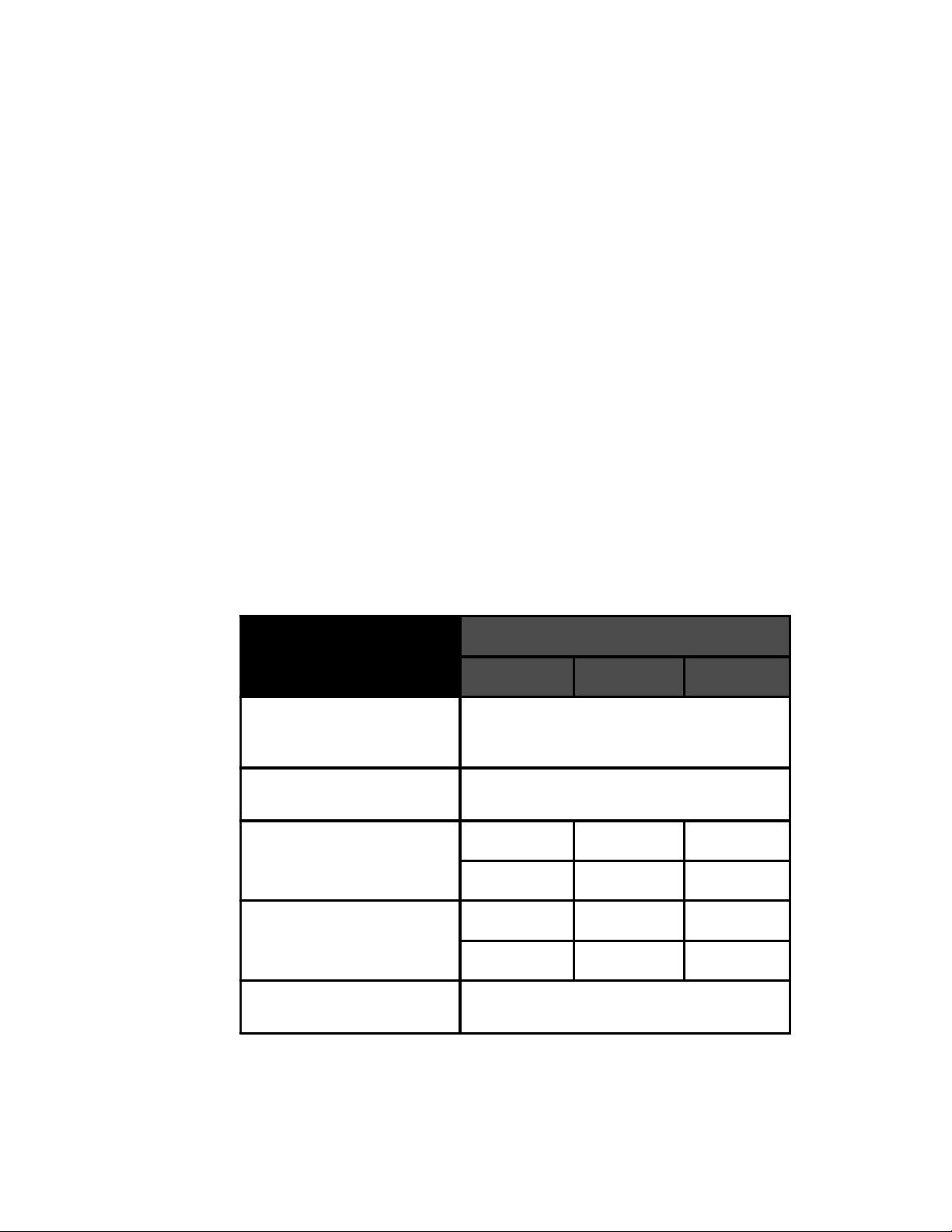
AC Voltage Window
Frequency Window
SET MAX SE LL AM P S
SET MAX CHARGE AMPS
TRACE ENGINEER IN G 3
Menu
SOFTWARE REV 4.10
SW4024 SW4048 SW5548
Fixed 106–132 VAC when SELL mode is
engaged (AC 1 i nput only). Adjustable for all
other modes.
59.3–60.5 Hz in SELL mode (AC1 input only),
54–66 Hz for all other modes.
1–35 1–35 1–50
Default 33 A Default 33 A Default 46 A
1–35 1–35 1–40
Default 30 A Default 30 A Default 35 A
REV 4 .10
976-0013-D-001
©2000 Xantrex Technology Inc.
1
Page 4

ADDENDUM
Changes in Manual:
Page-1, 5, 34, 39 and 119All references to software version 4.01 should now read 4.10.
Page 1 and 17The SW4024, SW4048 and SW5548 inverter models are UL listed to
UL1741-First Edition which incorporates IEEE929 recommended practices.
Labeling
Page 7 and 12The product rating labels have changed as shown below to reflect the UL listing:
270-0033-01-01
POWER INVERTER/CHARGER
STANDARD UL1741-1999
1st EDITION
NON-ISLANDING
55CL
UTILITY INTERACTIVE INVERTER
WITH INTEGRAL TRANSFOR MER
ISOLAT ION
POWER INVERTER/CHARGER
LISTED FOR CANADA
CAN/CSA-C22.2 No. 107.1-95
39FL
SW4024MODEL: SW4024____
------ INVERTER SYSTEM -----MAX CONTINUOUS AC OUTPUT POWER: 4000 VA
NOMINAL BATTERY BANK VOLTAGE: 24 VDC
NOMINAL DC OPERATING VOLTAGE: 25.2 VDC
RANGE OF OPER AT ING DC VOLTAGE: 2 2 -32 VDC
MAX OPERATING DC CURRENT: 200 AMPS DC
MAX SHORT CIRCUIT DC CURRENT: 800 AMPS DC
NOMINAL AC OUTPUT VOLTAGE: 120 VAC
NOMINAL AC OUTP UT FREQUENCY: 60 HZ
MAX CONTINUOUS AC OUTPUT CURRENT: 33.3 AMPS AC
MAX AC OUTPUT OVERCURRENT PROTECTION: 35 AMPS AC
MAX OUTPUT FAUL T AC CURRENT: 78 AMPS AC RMS
------ BATTERY CHARGER SYSTEM -- ---NOMINAL AC INPUT VOLTAGE: 120 VAC
OPERATING FREQUENCY RANGE: 54-66 HZ
MAX CONTINUOUS BATTERY CHARGER AC CURRENT: 30 AMPS AC
MAX CONTINUOUS BA TTERY CHARGER DC CURR EN T: 110 AMPS DC
MAX CONTINUOUS BA TTERY CHARGER INPUT VA: 3600 VA
TYPICAL BATTERY CHARGER POWER FACTOR: 0.9 TO 1.0
MAX AC TRANSFER SWITCH INPUT CURRENT: 60 AMPS AC
---- UTILITY INTERACTIVE SYSTEM ---OPERATING AC INPUT VOLTAGE RANGE: 106-132 VAC
OPERATING FREQUENCY RANGE (AC1): 59.3-60.5 HZ
MAX UTILITY AC BACKFEED CURRENT: 0 AMPS AC
MAX CONTINUOUS AC OUTPUT POWER: 4000 VA
OPERATING POWER FACTOR: 0.9 TO 1.0
XANTREX TECHNOLOGY - USA PATENT No. 5,373,433
5916 195TH ST. N.E. ARLINGTON, WA. 98223 USA
www.traceengineering.com
DATE MFD 1
QUARTER
23
1
1
YEAR
4 0100 0302 0504
1
270-0033-01-01
270-0032 -01-01
POWER INVERTER/ C H AR GE R
STANDARD UL1741-1999
1st EDITION
NON-ISLANDING
55CL
UTILITY INT ER ACT IVE INVERTER
WITH INTEGRAL TRANSFORMER
ISOLATION
POWER INVERTER/CHARGER
LISTED FOR CANADA
CAN/CSA-C22.2 No. 107.1-95
39FL
SW4048MODEL: SW4048____
------ INVERTER SYSTEM -----MAX CONTINUOUS AC OUTPUT POWER: 4000 VA
NOMINAL BAT T ERY BANK VOLTAGE: 48 VD C
NOMINAL DC OPERATING VOLTAGE: 50.4 VDC
RANGE OF OPER AT ING DC VOLTAGE: 44-66 VDC
MAX OPERATING DC CURRENT: 100 AMPS DC
MAX SHORT CIRCUIT DC CURRENT: 400 AMPS DC
NOMINAL AC OUTPUT VOLTAGE: 120 VAC
NOMINAL AC OUTP UT FREQUENCY: 60 HZ
MAX CONTINUOUS AC OUTPUT CURRENT: 33.3 AMPS AC
MAX AC OUTPUT OVERCURRENT PROTECTION: 35 AMPS AC
MAX OUTPUT FAULT AC CURRENT: 78 AMPS AC RMS
------ BATTERY CHARGER SYSTEM -----NOMINAL AC INPUT VOLTAGE: 120 VAC
OPERATING FREQUENCY RANGE: 54-66 HZ
MAX CONTINUOUS BATTERY CHARGER AC CURRENT: 30 AMPS AC
MAX CONTINUOUS BATTERY CHARGER DC CURRENT: 60 AMPS DC
MAX CONTINUOUS BATTERY CHARGER INPU T VA: 3600 VA
TYPICAL BATTERY CHARGER POWER FACTOR: 0.9 TO 1.0
MAX AC TRANSFER SWITCH IN PUT CURRENT: 60 AMPS AC
---- UTILITY INTERACT IVE SYSTEM ---OPERATING AC INPUT VOLTAGE RANGE: 106-132 VAC
OPERATING FREQUENCY RANGE (AC1): 59.3-60.5 HZ
MAX UTILITY AC BACK F EED CURRENT: 0 AMPS AC
MAX CONTINUOUS AC OUTPUT POWER: 4000 VA
OPERATING POWER FACTOR: 0.9 TO 1.0
XANTREX TECHNOLOGY - USA PATENT No. 5,373,433
5916 195TH ST. N.E. ARLINGTON, WA. 98223 USA
www.traceengineering.com
DATE MFD 1
QUARTER
23
1
1
YEAR
4 0100 0302 0504
1
270-0032-01-01
270-0031-01-01
POWER INVERTER/CHARGER
STANDARD UL1741-1999
1st EDITION
NON-ISLANDING
55CL
UTILITY INTERACTIVE INVERTER
WITH INTEGRAL TRANSFORMER
ISOLATION
POWER INVERTER/CHARGER
LISTED FOR CANADA
CAN/CSA-C22.2 No. 107.1-95
39FL
SW5548MODEL: SW5548____
------ INVERTER SYSTEM -- ---MAX CONTINUOUS AC OUTPUT POWER: 5500 VA
NOMINAL BATTERY BANK VOLT AGE: 48 VDC
NOMINAL DC OPERATING VOLTAGE: 50.4 VDC
RANGE OF OP ERATING DC VOL T AGE: 44-66 VDC
MAX OPERATING DC CURRENT: 140 AMPS DC
MAX SHORT CIRCUIT DC CURRENT: 400 AMPS DC
NOMINAL AC OUTPUT VOLTAGE: 120 VAC
NOMINAL AC OUTPUT FREQUENCY: 60 HZ
MAX CONTINUOUS AC OUTPUT CURRENT: 45.8 AMPS AC
MAX AC OUTPU T O V ERCURRENT PROT ECTION: 50 AMPS AC
MAX OUTPUT FAULT AC CURRENT: 78 AMPS AC RMS
------ BATTERY CHARGER SYSTEM -----NOMINAL AC INPUT VOLTAGE: 120 VAC
OPERATING FREQUE NCY RANGE: 54-66 HZ
MAX CONTINUOUS BATTERY CHARGER AC CURRENT: 35 AMPS AC
MAX CONTINUOUS BATTERY CHAR GER DC CURRENT: 70 AM P S DC
MAX CONTINUOUS BATTERY CHARGER INPUT VA: 4200 VA
TYPICAL BATTERY CHARGER POWER FACTOR: 0.9 TO 1.0
MAX AC TRANSFER SWITCH INPUT CURREN T: 60 AMPS AC
---- UTILITY INTERACTIVE SYSTEM ---OPERATING AC INPUT VOLTAGE RANGE: 106-132 VAC
OPERATING FREQUE NCY RANGE (AC1): 59.3-60.5 HZ
MAX UTILIT Y AC BACKFEED CURRENT: 0 AMPS AC
MAX CONTINUOUS AC OUTPUT POWER: 5500 VA
OPERATING POWER FACTOR: 0.9 TO 1.0
XANTREX TECHNOLOGY - USA PATENT No. 5,373,433
5916 195TH ST. N.E. ARLINGTON, WA. 98223 USA
www.traceengineering.com
DATE MFD 1
QUARTER
23
1
1
YEAR
4 0100 0302 0504
1
270-0031-01-01
Mounting
The second paragraph under MOUNTING should read as follows:
Use 1/4" minimum bolts for mounting. The mounting must capable of supporting four times the
weight of the inverter...
Add the following to the second paragraph:
When mounting to a vertical surface, such as a wall, ensure the inverter (or backing
material) is securely mounted to the wall studs for proper support.
Vertical wall mounting with proper access panels in place is the only UL approved
mounting method for fire prevention.
2
©2000 Xantrex Technology Inc.
Page 5

ADDENDUM
Menu Maps
The USER and SETUP menu have been updated to reflect the new software revision as follows:
Page 34USER MENU. The software revision shown under menu heading TRACE
ENGINEERING 3, menu item REVISION 4.01 is changed to REVISION 4.10.
An information file has been added to menu heading 11 and reads: IN SELL MODE AC1
INPUT VAC LIMITS FIXED AT 88% AND 110% OF NOMINAL.
Menu System
Page 39TRACE ENGINEERING (3) menu heading. The software revision has been updated
from 4.01 to 4.10.
Page 48The SET MAX CHARGE AMPS AC menu item, the range has been changed from
01 to 35 amps to 01 to 40 amps for the SW5548 model.
Page 54BATTERY SELLING (17) menu heading. The SET MAX SELL AMPS AC range has
been changed from 01 to 35 amps to 01 to 50 amps for SW5548 model.
Operation
Page 61 The following paragraph should be added to the UTILITY INTER-ACTIVE MODE
bulleted item: To meet agency approvals, SELL mode will sell power only between the locked
106132 volts AC range and 59.360.5 Hz range windows (120 VAC/60 Hz models only).
Page 83When in SELL mode, the SET INPUT LOWER LIMIT VAC is locked at 106 VAC and
sells power only when the AC output of the inverter is between 88 to 110% of nominal AC line
voltage.
Display Deletions
The following menu display items have been deleted for various reasons unrelated to UL
requirements.
Under the ERROR CAUSES 5 menu heading, menu item INVERTER BREAKER TRIPPED
has been deleted.
Under the GENERATOR MODE 2 menu heading, menu item GEN MAX RUN TIME ERROR
has been deleted.
Under the GENERATOR MODE 2 menu heading, all references to the GEN MAX RUN TIMER
have been deleted (i.e., IF GEN RUNS FOR MORE THAN MAX RUN TIME THEN ERROR).
Under GEN AUTO START SETUP 12 menu heading, all references to the GEN MAX RUN
TIMER have been deleted (i.e., SET MAXIMUM RUN TIME H:M 08:00 and SET MAX RUN TIME
TO 0 TO DEFEAT).
Utility Interactive Mode Islanding Protection Compliance
Trace SW inverters are capable of utility interactive operation, which includes utility protection
features to prevent injury and damage from occurring when power is sold to the utility grid. These
protective systems utilize high-speed microprocessor hardware and software to detect the abnormal
conditions and disconnect the inverter from the utility grid.
The UL1741 standard requires specific responses by the inverter to abnormal voltage and
frequency conditions. The following summarizes the voltage and frequency levels and the response
time period required, plus other features required by the UL1741 standard.
©2000 Xantrex Technology Inc.
3
Page 6

ADDENDUM
Over/Under Voltage Fluctuations
VOLTAGE MAXIMUM TRIP T IM E*
Voltage < 60 V (< 50%) 6 cycles
Voltages between 60–106 V (50–88%) 120 cycles
Voltages between 106–132 V (88–110%) Normal operation
Voltages between 132–165 V (110–137%) 120 cycles
Voltage >165 V (137%) 2 cycles
FREQUENCY MAXIMUM TRIP T IM E*
Frequency < 59.3 Hz 6 cycles
Frequency > 60.5 Hz 6 cycles
976-0013-D-002
*Trip time refers to the time between the abnormal conditions being applied and the inverter
ceasing to energize the utility line.
Over/Under Frequency Disturbances
Small renewable energy systems are allowed to sell within a fixed frequency range of -0.7 Hz/
+0.5 Hz of the nominal frequency in which they will operate. When the utility frequency is outside the
range of the nominal frequency window, the inverter must cease to energize the utility line within 6
cycles.
Reconnect Delay After a Utility Disturbance
An unacceptable utility event causes the renewable energy system to disconnect from the utility
line. It will remain disabled until acceptable voltage and frequency have been maintained for a
minimum of five minutes. After the 5 minute timer is complete, the inverter is allowed to
automatically reconnect the renewable energy system to the utility.
Islanding Protection
The non-islanding inverter protection features required by UL1741 ensures that the inverter
ceases to energize the utility line when the inverter is subjected to island conditions. As a result,
active control techniques have been incorporated into the SW inverter for detecting potential
dispersed-generation islands.
A utility wishing to ensure against renewable-energy supported dispersed-generation islanding
may require the use of a non-islanding inverter. Trace has designed the new software protection
system to comply with the requirements of the non-islanding inverter section of UL1741.
Over-current Protection
The Trace SW Series inverters also include over-current protection for the inverter system.
This protective system is used if the inverter attempts to power too large of a load or if the inverter
loses synchronization with the utility grid. This protective system is implemented with redundant
systems in analog hardware, microprocessor software and with a mechanical device (circuit
breaker). This insures the inverter is protected from damage and can not create an unsafe fault
condition to the utility or residence.
4
©2000 Xantrex Technology Inc.
Page 7

©2000 Xantrex Technology Inc.
Page 8

5916 - 195th Street N.E., Arlington, WA 98223 Phone: (360) 435-8826 Fax: (360) 435-2229
visit our website at: www.traceengineering.com
 Loading...