

Page 1

Internal Ethernet and
RS-232 Interface for
XFR Series
Programmable DC
Power Supplies
ENET-XFR
ENET-XFR3
Operating Manual
Page 2

Page 3

XFR 1.2kW and 2.8kW
Ethernet/RS-232 Interface
Option
Operating Manual
Page 4

About Xantrex
Xantrex Technology Inc. is a world-leading supplier of advanced power electronics and controls with
products from 50 watt mobile units to one MW util ity-s cale system s for wind, sol ar , ba tteri es, fuel cel ls,
microturbin es, and backup powe r appl icat ions in bot h grid- connec ted and sta nd-alone systems . Xantrex
products inc lude inverters, battery chargers, programmable power supplies, and variable speed drives
that convert, su pply, control, clea n, and distribute elec trical power.
Trademarks
XFR 1.2kW and 2.8kW Ethernet/RS-232 Interface Option is a trade mark of Xantrex International.
Xantrex is a registe r ed trademark of Xantrex International.
Other trademar ks, registered trademarks, and product names are the property of their respective owners
and are us ed herein for identification purposes only.
Notice of Copyright
XFR 1.2kW and 2.8kW Ethernet/RS-232 Interface Option Operating Manual © April 2004 Xantrex
Intern ational. All rights reserved.
Disclaimer
UNLESS SPECIFICALLY AGREED TO IN WRITING, XANTREX TECHNOLOGY INC.
(“XANTREX”)
(a) MAKES NO WARRANTY AS TO THE ACCURACY, SUFFICIENCY OR SUITABILITY OF
ANY TECHNICAL OR OTHER INFORMATION PROVIDED IN ITS MANUALS OR OTHER
DOCUMENTATION.
(b) ASSUMES NO RESPONSIBILITY OR LIABILITY FOR LOSS OR DAMAGE, WHETHER
DIRECT, INDIRECT, CONSEQUENTIAL OR INCIDENTAL, WHICH MIGHT ARISE OUT OF
THE USE OF SUCH INFORMATION. THE USE OF ANY SUCH INFORMATION WILL BE
ENTIRELY AT THE USER’S RISK.
Date and Revision
April 2004 Revi si on B
Part Number
TM-XR9B-01XN
Contact Information
Telephone: 1 800 670 0707 (toll free North America)
1 360 925 5097 (direct)
Fax: 1 800 994 7828 (toll free North America)
1 360 925 5143 (direct)
Email: customerservice@xantrex.com
Web: www.xantrex.com
Telephone: 1 800 670 0707 (toll free North America)
1 360 925 5097 (direct)
Page 5

About This Manual
Purpose
This Operating Manual is for the XFR 1.2kW and 2.8kW Ethernet/RS-
232 Interface Option; a microproces sor-controlled option card for all
models of XFR Seri es DC output power supplies. This manual provides
you with specifications, user options, and configuration instructions for
the interface, along with a command set whic h allows you to control
your power supply from a computer console. Error messages and
calibration proc edures are also included.
Scope
This Operating Manual covers the inter face only. Refer to your power
supply manual for install ation, configuratio n, an d operating procedures
for your power supply.
Audience
This manual is de signed for t he user who is fami liar with bas ic el ectrica l
theory especiall y as it applie s to the operation of power supplies. This
implies a recognition of C onstant Voltage and Constant Current
operation modes and the control of input and output power, as well as
the observance of safe techniques while effecting supply or pin
connections and any changes in switch settings. The user should also
have experience with networ k-based communications software and
protocols.
iii
Page 6

About This Manual
Organization
This Manual is organized into 4 chapters and 2 appendixes.
Chapter 1, “Features” Desc ribe s the in terface an d lists its featu r e s .
Chapter 2, “In stallation and Configuration” Explains basic setup
procedures for Ethernet mode and RS-232 mode. Describes inspection,
cleaning, shipping, and storage procedure s.
Chapter 3, “Operation” Lists the complete command set, status
registers, and error codes.
Chapter 4, “Calibration” Provides detail ed procedures f or volta ge and
current mode calibration as well as ove r voltage protection (OVP)
calibration. Includes calibration for programming and readback accuracy.
Appendix A, “Spec ifications ” Details the interface specifications.
Appendix B, “Advanc ed Ethernet Administration” Details how to
change network pa ssword, view port sta tistics and interpre t LED
information.
“Warranty and Product Information” Explains Warranty and return
information.
iv TM-XR9B-01XN
Page 7
Conventions Used
The following conventions are used in this guide.
Note: These notes des cribe an i mportant a ction item o r an i tem that you
must pay attention to.
About This Manual
WARNING
W arnings ident ify condition s that could result in pe rsonal injury
or loss of life.
CAUTION
Cautions identify conditions or practices that could result in
damage to the unit or other equipment.
Important:
know , but not as serious as a caution or warning.
These notes describe thin gs which are important for you to
Related Information
You can find more information about Xantrex Technology Inc. as well as
its products and servic es at www.xantrex.com
TM-XR9B-01XN v
Page 8

vi
Page 9
Important Safety Instructions
WARNING: High Energy and High Voltage
Exercise caution when using a nd calibrating a power supply.
High energy le vels can be stor ed at the output volta ge te rminals
on a power supply in normal operation. In addition, potential ly
lethal voltages exist in the power circuit and on the output and
sense connectors of a power supply with a rated output greater
than 40 V. Filter capacitors sto re potentially dangerous energy
for some time aft er po w er is rem ov ed .
CAUTION
Operate the power supply in an environment free of flammable
gases or fumes. To ensure that the power supply’ s safe ty
features are not compromised, use the power supply as specified
in this manual and do not substitute parts or make any
unauthorized modifications. Conta ct the service technician for
service and repair help. Repairs must be made by experienced
service technicians only.
vii
Page 10

viii
Page 11

Contents
Important Safety Instructions
1
Features
Description - - - - - - - - - - - - - - - - - - - - - - - - - - - - - - - - - - - - - - - - - - - - - - - - - -1–1
Features and Functions - - - - - - - - - - - - - - - - - - - - - - - - - - - - - - - - - - - - - - - - - -1–2
Interface Features - - - - - - - - - - - - - - - - - - - - - - - - - - - - - - - - - - - - - - - - - - -1–2
Ethernet Features - - - - - - - - - - - - - - - - - - - - - - - - - - - - - - - - - - - - - - - - - - -1–3
Programmable Functions - - - - - - - - - - - - - - - - - - - - - - - - - - - - - - - - - - - - - -1–3
Readback Functions - - - - - - - - - - - - - - - - - - - - - - - - - - - - - - - - - - - - - - - - -1–3
2
Installation and Configuration
Introduction - - - - - - - - - - - - - - - - - - - - - - - - - - - - - - - - - - - - - - - - - - - - - - - - -2–1
Initial Inspection - - - - - - - - - - - - - - - - - - - - - - - - - - - - - - - - - - - - - - - - - - - - - -2–3
Front Panel - - - - - - - - - - - - - - - - - - - - - - - - - - - - - - - - - - - - - - - - - - - - - - -2–4
Ethernet/ RS -2 32 Int erf ace Subplate and PCB - - - - - - - - - - - - - - - - - - - - - - - -2–5
Changing Internal Jumpers - - - - - - - - - - - - - - - - - - - - - - - - - - - - - - - - - - - - - - -2–8
Procedure for 1.2kW XFR - - - - - - - - - - - - - - - - - - - - - - - - - - - - - - - - - - - - -2–8
Procedure for 2.8kW XFR - - - - - - - - - - - - - - - - - - - - - - - - - - - - - - - - - - - - -2–9
Basic Setup Procedure - Ethernet - - - - - - - - - - - - - - - - - - - - - - - - - - - - - - - - - -2–10
Basic Setup Procedure - RS-232- - - - - - - - - - - - - - - - - - - - - - - - - - - - - - - - - - -2–11
Configuring for Etherne t or RS-232 - - - - - - - - - - - - - - - - - - - - - - - - - - - - - - - - 2–12
Ethernet Communicatio ns - - - - - - - - - - - - - - - - - - - - - - - - - - - - - - - - - - - - - - -2–13
Ethernet Connection - - - - - - - - - - - - - - - - - - - - - - - - - - - - - - - - - - - - - - - - 2–13
Connecting to a Network - - - - - - - - - - - - - - - - - - - - - - - - - - - - - - - - - - 2–13
Connecting Directly to your Computer - - - - - - - - - - - - - - - - - - - - - - - - - 2–13
Locating the Power Supply on Your Network - - - - - - - - - - - - - - - - - - - - - - - 2–14
Configuring Etherne t Bridge - - - - - - - - - - - - - - - - - - - - - - - - - - - - - - - - - -2–15
Installing and Using Real Port® - - - - - - - - - - - - - - - - - - - - - - - - - - - - - - - - -2–16
Background - - - - - - - - - - - - - - - - - - - - - - - - - - - - - - - - - - - - - - - - - - - 2–16
Installation - - - - - - - - - - - - - - - - - - - - - - - - - - - - - - - - - - - - - - - - - - - - 2–16
Using RealPort® - - - - - - - - - - - - - - - - - - - - - - - - - - - - - - - - - - - - - - - - 2–16
RS-232 Communications - - - - - - - - - - - - - - - - - - - - - - - - - - - - - - - - - - - - - - - 2–17
RS-232 Connection - - - - - - - - - - - - - - - - - - - - - - - - - - - - - - - - - - - - - - - - - 2–17
- - - - - - - - - - - - - - - - - - - - - - - - - - - - - - - - - vii
TM-XR9B-01XN ix
Page 12

Contents
Baud Rate Selection - - - - - - - - - - - - - - - - - - - - - - - - - - - - - - - - - - - - - - - - 2–18
Flow Control Selection - - - - - - - - - - - - - - - - - - - - - - - - - - - - - - - - - - - - - - 2–19
Remote/Local Operation- - - - - - - - - - - - - - - - - - - - - - - - - - - - - - - - - - - - - - - - 2–20
Remote/Local Mode Startup - - - - - - - - - - - - - - - - - - - - - - - - - - - - - - - - - - 2–20
Remote Mode Operation - - - - - - - - - - - - - - - - - - - - - - - - - - - - - - - - - - - - - 2–21
Local Mode Operation - - - - - - - - - - - - - - - - - - - - - - - - - - - - - - - - - - - - - - 2–22
Remote Enable (REN) Command - - - - - - - - - - - - - - - - - - - - - - - - - - - - - - - 2–22
Local Lockout (LLO) Command - - - - - - - - - - - - - - - - - - - - - - - - - - - - - - - 2–23
Power Supply Settings - - - - - - - - - - - - - - - - - - - - - - - - - - - - - - - - - - - - - - - - - 2–23
Additional User Options and Settings - - - - - - - - - - - - - - - - - - - - - - - - - - - - - - - 2–24
OVP Selection - - - - - - - - - - - - - - - - - - - - - - - - - - - - - - - - - - - - - - - - - - - - 2–24
TTL Shutdown Polarity - - - - - - - - - - - - - - - - - - - - - - - - - - - - - - - - - - - - - - 2–25
User Signals - - - - - - - - - - - - - - - - - - - - - - - - - - - - - - - - - - - - - - - - - - - - - - - - 2–26
User Lines Connector - - - - - - - - - - - - - - - - - - - - - - - - - - - - - - - - - - - - - - - 2–26
User Lines Cable Connection - - - - - - - - - - - - - - - - - - - - - - - - - - - - - - - - - - 2–28
3
Operation
Introduction - - - - - - - - - - - - - - - - - - - - - - - - - - - - - - - - - - - - - - - - - - - - - - - - - 3–1
RS-232 Operation - - - - - - - - - - - - - - - - - - - - - - - - - - - - - - - - - - - - - - - - - - - - - 3–2
Ethernet Operation- - - - - - - - - - - - - - - - - - - - - - - - - - - - - - - - - - - - - - - - - - - - - 3–2
Command Syntax - - - - - - - - - - - - - - - - - - - - - - - - - - - - - - - - - - - - - - - - - - - - - 3–2
Manual Conventions - - - - - - - - - - - - - - - - - - - - - - - - - - - - - - - - - - - - - - - - - 3–2
Command Format and Parameters - - - - - - - - - - - - - - - - - - - - - - - - - - - - - - - - 3–3
Floating Point Number <float> - - - - - - - - - - - - - - - - - - - - - - - - - - - - - - - 3–4
Command Strings - - - - - - - - - - - - - - - - - - - - - - - - - - - - - - - - - - - - - - - - - - - 3–5
Command Terminators - - - - - - - - - - - - - - - - - - - - - - - - - - - - - - - - - - - - - - - 3–5
Order - - - - - - - - - - - - - - - - - - - - - - - - - - - - - - - - - - - - - - - - - - - - - - - - - - - 3–5
Command Summary - - - - - - - - - - - - - - - - - - - - - - - - - - - - - - - - - - - - - - - - - - - 3–6
Command Reference - - - - - - - - - - - - - - - - - - - - - - - - - - - - - - - - - - - - - - - - - - - 3–9
Accumulated Status, Status, and Fault Registers- - - - - - - - - - - - - - - - - - - - - - - - 3–17
Error Codes - - - - - - - - - - - - - - - - - - - - - - - - - - - - - - - - - - - - - - - - - - - - - - - - 3–19
Troubleshooting - - - - - - - - - - - - - - - - - - - - - - - - - - - - - - - - - - - - - - - - - - - - - 3–20
Diagnostic LEDs - - - - - - - - - - - - - - - - - - - - - - - - - - - - - - - - - - - - - - - - - - 3–20
Computer Operating Properly (COP) LEDs - - - - - - - - - - - - - - - - - - - - - 3–20
Ethernet Mode Troubleshooting Tips - - - - - - - - - - - - - - - - - - - - - - - - - - - - - 3–21
RS-232 Mode Troubleshooting Tips - - - - - - - - - - - - - - - - - - - - - - - - - - - - - 3–23
RS-232 and/or Ethernet Mode Troubleshooting Tips - - - - - - - - - - - - - - - - - - 3–23
x TM-XR9B-01XN
Page 13

4
Calibration
Introduction - - - - - - - - - - - - - - - - - - - - - - - - - - - - - - - - - - - - - - - - - - - - - - - - -4–1
Voltage Mode Calibration - - - - - - - - - - - - - - - - - - - - - - - - - - - - - - - - - - - - - - - -4–3
Voltage Calibration Setup - - - - - - - - - - - - - - - - - - - - - - - - - - - - - - - - - - - - -4–3
Voltage Program Calibration Procedure - - - - - - - - - - - - - - - - - - - - - - - - - - - -4–3
Voltage Readback Calibration Procedure - - - - - - - - - - - - - - - - - - - - - - - - - - -4–4
Current Mode Calibration - - - - - - - - - - - - - - - - - - - - - - - - - - - - - - - - - - - - - - - -4–5
Current Calibration Setup - - - - - - - - - - - - - - - - - - - - - - - - - - - - - - - - - - - - -4–5
Current Program Calibration Procedure - - - - - - - - - - - - - - - - - - - - - - - - - - - -4–5
Current Readback Calibration Procedure - - - - - - - - - - - - - - - - - - - - - - - - - - -4–6
Over Voltage Protection (OVP) Calibration - - - - - - - - - - - - - - - - - - - - - - - - - - - -4–7
A
Specifications
Specifications for XFR 1.2kW with Ethernet/RS-232 Interface Installe d- - - - - - - - A – 2
Specifications for XFR 2.8kW with Ethernet/RS-232 Interface Installe d- - - - - - - - A – 4
B
Advanced Ethernet Administration
Changing the Root Password - - - - - - - - - - - - - - - - - - - - - - - - - - - - - - - - - - - - - B–2
Resetting the Configuration to Defaults - - - - - - - - - - - - - - - - - - - - - - - - - - - - - - B–3
Introduction - - - - - - - - - - - - - - - - - - - - - - - - - - - - - - - - - - - - - - - - - - - - - - B–3
Resetting the Configuration from a Browser - - - - - - - - - - - - - - - - - - - - - - - - B–3
Copying the Configurati on to and from a Server- - - - - - - - - - - - - - - - - - - - - - - - B–4
Viewing Port Statistics and Settings - - - - - - - - - - - - - - - - - - - - - - - - - - - - - - - - B–4
Viewing Network Statistics - - - - - - - - - - - - - - - - - - - - - - - - - - - - - - - - - - - - - - B–4
Interpreting LED Information - - - - - - - - - - - - - - - - - - - - - - - - - - - - - - - - - - - - B–5
Contents
Warranty and Product Information
TM-XR9B-01XN xi
- - - - - - - - - - - - - - - - - - - - - - - - - -WA–1
Page 14

xii
Page 15

Figures
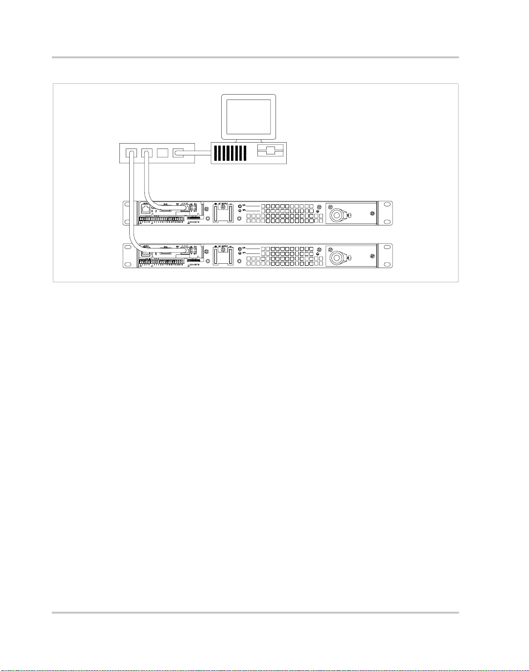
Figure 1-1 Sample configuration using Ethernet/RS-232 Interface
(1200 Watt DC Power Supplies Shown) - - - - - - - - - - - - - - - - - - - - 1–2
Figure 2-1 Power Supply Front Panel with Ethernet/RS-232 I nterface Installed
(1200 Watt Power Supply Shown) - - - - - - - - - - - - - - - - - - - - - - - - 2–4
Figure 2-2 Ethernet/ RS -2 32 Int erf ace Subplate - - - - - - - - - - - - - - - - - - - - - - - 2–5
Figure 2-3 Ethernet/ RS -2 32 Int erf ace PCB - - - - - - - - - - - - - - - - - - - - - - - - - - 2–6
Figure 2-4 Removing the PCB- - - - - - - - - - - - - - - - - - - - - - - - - - - - - - - - - - - 2–8
Figure 2-5 RS-232 Connector Pinouts- - - - - - - - - - - - - - - - - - - - - - - - - - - - - 2–17
Figure 2-6 User Lines Signal Connector Circuit Block Diagram - - - - - - - - - - - 2–27
Figure 2-7 User Lines Cable with Ferrite Block - - - - - - - - - - - - - - - - - - - - - - 2–28
Figure 4-1 Voltage Calibration Setup - - - - - - - - - - - - - - - - - - - - - - - - - - - - - - 4–3
Figure 4-2 Current Calibration Setup - - - - - - - - - - - - - - - - - - - - - - - - - - - - - - 4–5
Figure B-1 Ethernet Bridge LEDs- - - - - - - - - - - - - - - - - - - - - - - - - - - - - - - - - B–5
TM-XR9B-01XN xiii
Page 16

xiv
Page 17

Tables
Table 2-1 Remote Programming LEDs - - - - - - - - - - - - - - - - - - - - - - - - - - - - 2–4
Table 2-2 Ethernet/RS -23 2 Int erf ace Jumper Selections - - - - - - - - - - - - - - - - - 2–7
Table 2-3 Ethernet Setup P rocedure - - - - - - - - - - - - - - - - - - - - - - - - - - - - - 2–10
Table 2-4 RS-232 Setup Procedur e - - - - - - - - - - - - - - - - - - - - - - - - - - - - - - 2–11
Table 2-5 Jumper positions for Ethernet or RS-232 - - - - - - - - - - - - - - - - - - - 2–12
Table 2-6 Jumper J2 Settings f or Baud Rate - - - - - - - - - - - - - - - - - - - - - - - - 2–18
Table 2-7 Jumper J2 Flow Control Section - - - - - - - - - - - - - - - - - - - - - - - - - 2–19
Table 2-8 Jumper J2 Flow Control Prot ocol Selection - - - - - - - - - - - - - - - - - 2–19
Table 2-9 Jumper J2 Remote/Loc al Start-up Settings. - - - - - - - - - - - - - - - - - 2–20
Table 2-10 Remote Mode Power On Conditions- - - - - - - - - - - - - - - - - - - - - - 2–21
Table 2-11 Power Supply Settings - - - - - - - - - - - - - - - - - - - - - - - - - - - - - - - 2–23
Table 2-12 OVP Control Mode Select ion- - - - - - - - - - - - - - - - - - - - - - - - - - - 2–24
Table 2-13 Jumper Set tings for TTL Shutdown Circuit Logic - - - - - - - - - - - - - 2–25
Table 2-14 User Signals Connector- - - - - - - - - - - - - - - - - - - - - - - - - - - - - - - 2–26
Table 3-1 Command Parameters- - - - - - - - - - - - - - - - - - - - - - - - - - - - - - - - - 3–4
Table 3-2 Floating Point Numbers - - - - - - - - - - - - - - - - - - - - - - - - - - - - - - - 3–4
Table 3-3 Programming Commands - - - - - - - - - - - - - - - - - - - - - - - - - - - - - - 3–6
Table 3-4 Query Commands - - - - - - - - - - - - - - - - - - - - - - - - - - - - - - - - - - - 3–7
Table 3-5 Calibration Commands - - - - - - - - - - - - - - - - - - - - - - - - - - - - - - - - 3–8
Table 3-6 Status Commands - - - - - - - - - - - - - - - - - - - - - - - - - - - - - - - - - - - 3–8
Table 3-7 Command Reference - - - - - - - - - - - - - - - - - - - - - - - - - - - - - - - - - 3–9
Table 3-8 Accumulated St atus, Status and Fault Registers - - - - - - - - - - - - - - 3–18
Table 3-9 Error Codes- - - - - - - - - - - - - - - - - - - - - - - - - - - - - - - - - - - - - - - 3–19
Table 3-10 Ethernet Mode Tips - - - - - - - - - - - - - - - - - - - - - - - - - - - - - - - - - 3–21
Table 3-11 RS-232 Mode Tips- - - - - - - - - - - - - - - - - - - - - - - - - - - - - - - - - - 3–23
Table 3-12 RS-232 and/or Ethernet Mode Tips- - - - - - - - - - - - - - - - - - - - - - - 3–23
Table A-1 XFR 1.2kW 7.5 V to 40 V- - - - - - - - - - - - - - - - - - - - - - - - - - - - - - A–2
Table A-2 XFR 1.2kW 60 V to 600 V - - - - - - - - - - - - - - - - - - - - - - - - - - - - - A–3
Table A-3 XFR 2.8kW 7.5 V to 40 V- - - - - - - - - - - - - - - - - - - - - - - - - - - - - - A–4
Table A-4 XFR 2.8kW 60 V to 600 V - - - - - - - - - - - - - - - - - - - - - - - - - - - - - A–5
Table B-1 Ethernet Bridge LEDs Interpretation - - - - - - - - - - - - - - - - - - - - - - - B–5
TM-XR9B-01XN xv
Page 18

xvi
Page 19

1
Description
Features
The Ethernet/RS-232 Interface is a microprocessor-controlled
option card for all models of the XFR series of DC output power
supply. Installed internally, the interface card allows you to
remotely control your power supply through your existing
network, or via a direct connection to your computer. It features
an auto-sensing 10/100Base-T network interface that provides fast
programming and readback utilizing an extensive command set.
You are able to select between Ethernet (factory default) or RS-
232 control by adjusting internal jumpers on the interface card.
Page 20
Features
CONTROLLER
HUB
Figure 1-1
Sample configuration using Ethernet/RS-232 Interface
(1200 Watt DC Power Supplies Shown)
Features and Functions
Interface Features
• Programmable soft limits for voltage and current
• Programmable over voltage protection with reset
• Easy-to-use, self-documenting command set
• Standardized commands for complete communic ation wit h any of th e
supplies in the system
• User-programmable isolated fault, polarity, isolation, and auxiliary,
user-defined outp ut signals.
• LED status signals: error, address, remote/local operation, and over
voltage protection.
• Foldback in CV or CC mode with reset
• Software calibration
1–2 TM-XR9B-01XN
Page 21

Ethernet Features
• Auto-sensing 10/100Base-T network interface
• Robust onboard TCP/IP stack supports:
•TCP/UDP
• UDP Multicast
• Universal IP Address Assignment via:
• DHCP
•RARP
•ARP-Ping
• Easy configuration via web browser (HTTP)
• RealPort® COM/TTY port redirection software
• Status LEDs for Link, Activity, and Diagnostics
• Reset switch to reboot Ethernet Bridge
Programmable Functions
• Output voltage and current
• Soft limits for voltage and current
• Over voltage protection
• Output enable/disable
• Maskable fault interrupt
• Hold and trigger
• Output relay signals
Features and Functions
Readback Functions
• Actual voltage and current
• Voltage and current settings
• Soft voltage and current limits
• Over voltage protection se tting
• Present and accumulated power supply status
• Programming error codes
• Fault codes
• Power supply model and software version identification
TM-XR9B-01XN 1–3
Page 22

1–4
Page 23

Installation and
2
Introduction
Configuration
The Ethernet/RS-232 Interface is usually installed at the factor y. Your
local distributor or service center can also install the interface,
especially for use in a previously-purchased supply already on site. You
must then configure the Inter f ace-enhanced supply for your system
using the “Basic Setup Procedur e - Ethernet” on page 2–10, or the
“Basic Setup Procedure - RS-232” on page 2–11.
To use this product, you must have the following equipment:
• a Xantrex XFR DC output power supply
• computer-based communications software package
Page 24

Installation and Configuration
Also, depending on your specific configuration, you will need additional
items.
For Ethernet (via network):
• CAT 5 network cable to connect XFR to your network
• computer connected to the network
For Ethernet (direct to computer):
• CAT 5 crossover cable to connect XFR directly to your computer
• computer with network interface card (NIC)
For RS-232:
• null modem serial cable (cross over)
• computer with an RS-232 interface (serial/COM port)
2–2 TM-XR9B-01XN
Page 25
Initial Inspection
On first receiving your unit, perform a quick physical check.
• Ensure each package contains a power supply with its Ethernet/RS-
232 Interface board installed, and manuals for the power supply and
the Ethernet/RS-232 Interface. Any additional parts shipped with the
power supply will be identifie d in the supply's documentation.
• Inspect the unit for any signs of physical damage such as scratches,
cracks, or broken switches, connectors, or displays.
• Check the printed circuit boa rd and components if you suspect
internal damage.
If the unit is damaged, save all packing materials and notify the carrier
immediately. For additional information, plea se see the section titles,
“Returning Power Supplies to the Manufacturer” in the manual shipped
with your complete unit.
Initial Inspection
CAUTION
If you remove the unit's cover, use proper static control
techniques to avoid damage to static-sensitive components on
the printed circuit board.
CAUTION
Use proper static control techniques to avoid damage to staticsensitive components on the printed circuit board.
TM-XR9B-01XN 2–3
Page 26
Installation and Configuration
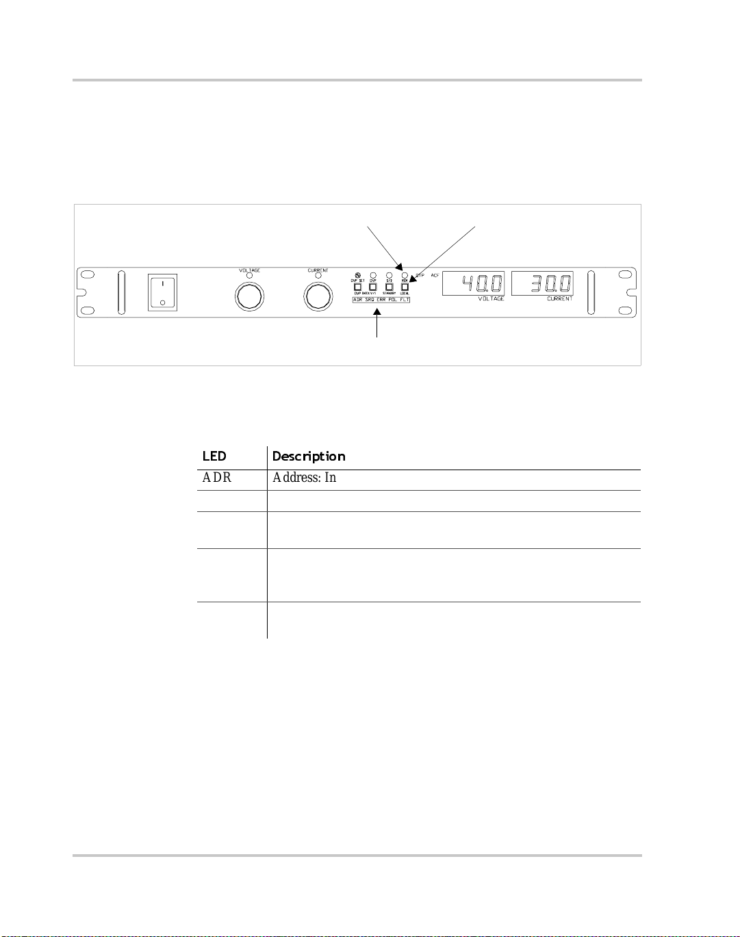
Front Panel
Figure 2-1 shows the front panel of an XFR 1200 Watt supply with
Ethernet/ RS -2 32 Int erf ace installed. There is a further desc ription of the
Remote Programming LEDs in Table 2-1.
Remote Programming LEDs. See table.
Local Switch (LOCAL)Remote LED (REM)
Figure 2-1
Power Supply Front Panel with Ethernet/RS-232 Interface Installed
(1200 Watt Power Supply Shown)
Table 2-1
LED Description
ADR Address : Indicates that the m aster controller is addressing t he unit.
SRQ Service Request: (GPIB only)
ERR Error: Indicate s when a programming error has occurred. You can
FLT Fault: Indicates that a fault has occurred. The fault bit must be
POL Polarity: Indicates that the polarit y use r line has been activated.
Remote Programming LEDs
clear the ERR LED with an error query command.
unmasked. Refer to the status register in Table 3-8 on page 3–18.
Momentarily lights if PON SRQ is set to on.
See “User Lines Connector” on page 2–26.
2–4 TM-XR9B-01XN
Page 27
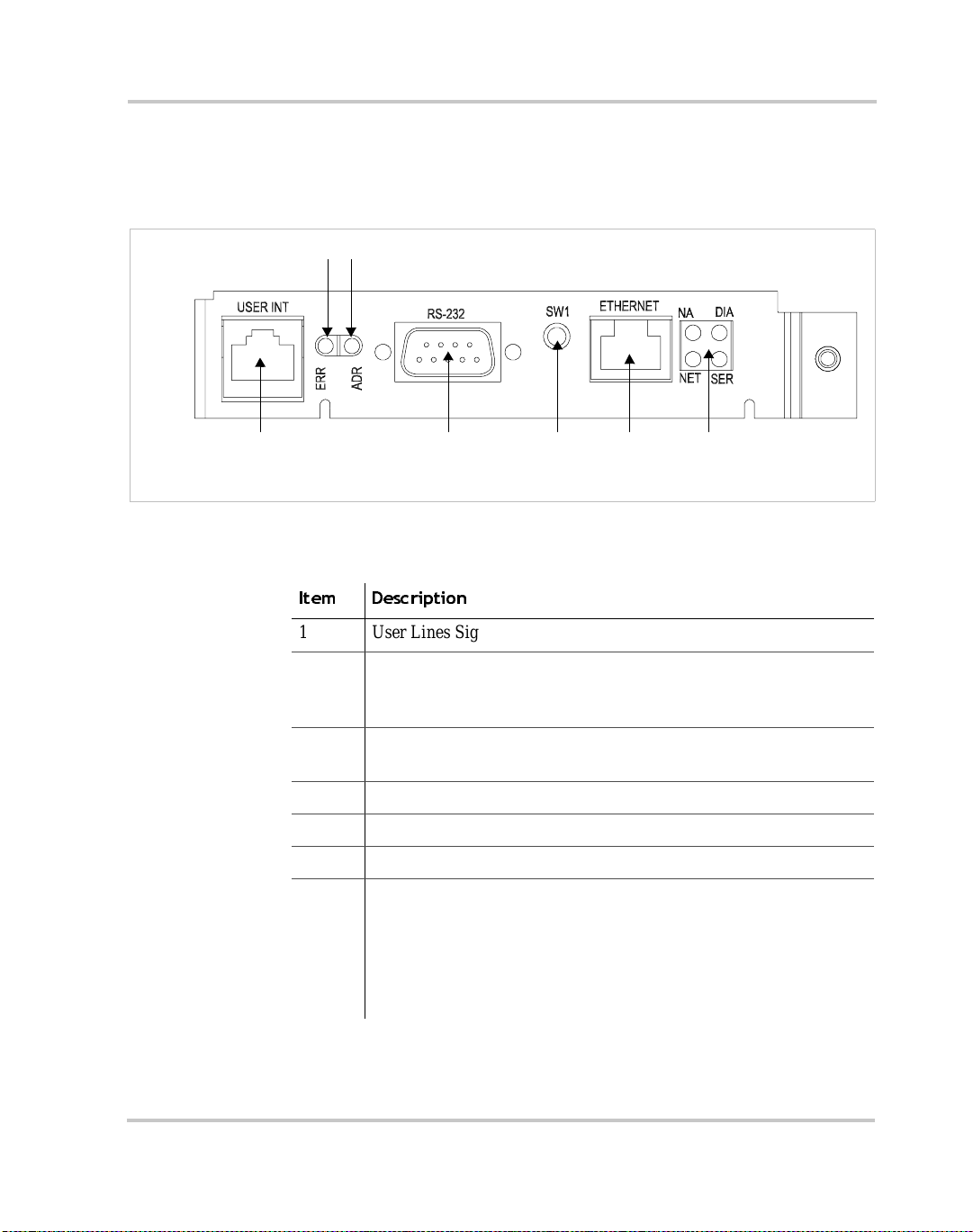
Ethernet/RS-232 Interface Subplate and PCB
The Ethernet/RS-232 Interface Subplate is visible from the rear panel of
the unit. Rear panel components are identified in Figure 2-2.
3
2
Initial Inspection
1
Note: On some models, the subplate is rotated 180 degrees.
Figure 2-2
Ethernet/RS-232 Interface Subplate
4
(XFR 1.2kW shown - located on power supply rear cover)
Item Description
1 User Lines Signal Connector
2 Error LED (ERR)
Indicates that a programming error has occurred.
Clear with error query command.
3 Address LED (ADR)
Indicates that the unit is being addres sed by the master controller.
4 RS-232 Connector
5 Ethernet Br idge Reset Switch
6 RJ45 Ethernet Connector
7 Ethernet Bridge LEDs
NA: Reserved
DIA: Diagnostics
NET: Network link status
SER: Serial port activity
See page B–5.
5
6
7
TM-XR9B-01XN 2–5
Page 28
Installation and Configuration
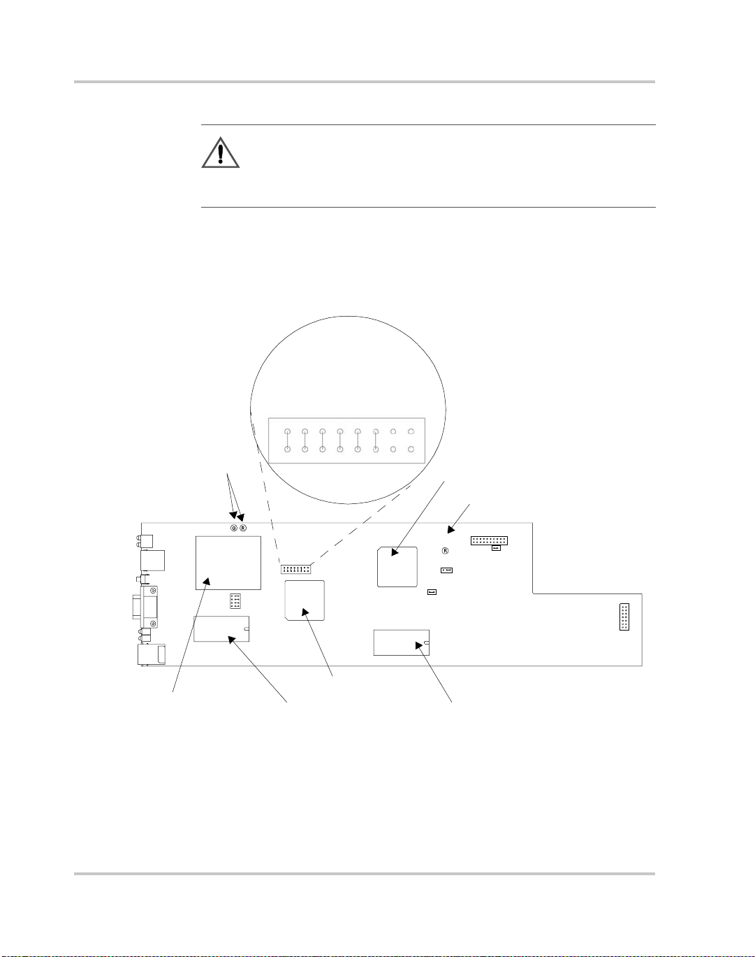
Figure 2-3 shows the inte rnal components on the Ethernet/RS-232
Interface PCB. Table 2-5 shows which jumpers need to be modified to
change modes or settings.
CAUTION
Use proper static control techniques to avoid damage to staticsensitive components on the printed circuit board
PONREM
XON
B3
B2
FLW
B1
NA
NA
Subplate
Ethernet Bridge
Figure 2-3
COP LEDs
CR167
CR166
J3
J4
J5
J6
123
J2
J2
Master EPROM
Ethernet/RS-232 Interface PCB
J103
Master Controller
Slave Controller
COP LED
J64
J65
1
3
J93
1
CR89
2
Slave EPROM
1
J1
2–6 TM-XR9B-01XN
Page 29
Initial Inspection
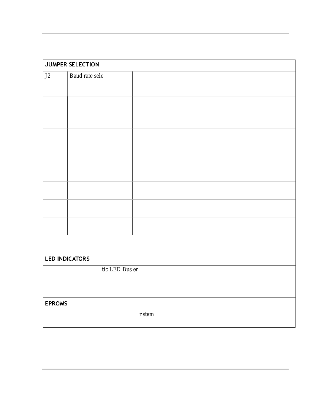
Table 2-2
JUMPER SELECTION
J2 Baud rate selection
J2 RS-232 flow control
J2 Unused (11-12) [closed] [default] Provides extra jumper.
J2 Power-On remote/local page 2–20 PONREM (15-16) [open] [default] PON in remote.
J3, J4,
J5, J 6
J65 Local OVP control
J93 User TTL shutdown (S/D)
J103 Remote OVP control
Ethernet/RS-232 Interface Jumper Selections
page 2–18 B1 (5-6) [closed] [default]
(default 9600)
page 2–19 FLW (7-8) [c losed] [default] Flow control disabled.
selection hardware (RTS /
CTS) or software (X ON/
XOFF)
Ethernet or RS232 mode page 2–12 (2-3) [default] Ethernet.
page 2–24 [closed] [default]
selection
page 2–25 (1-2) User TTL S /D line active low.
selection
page 2–24 [closed] [default]
selection
B2 (3-4) [closed] [default]
B3 (1-2) [closed] [default]
FLW (7-8) [open] Flow control enabled.
XON (9-10) [closed] [default] Hardware flow control.
XON (9-10) [open] Software flow control.
(13-14) [open] Not used.
PONREM (15-16) [closed] PON in local.
(1-2) RS232.
[open] Front Panel OVP Control.
(2-3) [default] User TTL S/D line active high.
[open]
Note: All other jumpers are not user-selectable.
LED INDICATORS
CR89 Red Diagnostic LED Bus error or Soft restart on Master circuitry
CR166 Red Diagnosti c LED Sof t restart on Master circuitry
CR167 Green Diagnostic LED Bus error on Master circuitry
Refer to “Tr oubleshooting” on page 3–20 for more information on these LEDs.
EPROMS
Slave EPROM See revision number stamped on EPROM
Master EPROM See revision numb er stamped on EPROM
TM-XR9B-01XN 2–7
Page 30
Installation and Configuration
Changing Internal Jumpers
Some of the settings on the Ethernet/RS-232 Interface card are user
selectable by way of jumpers on the print ed circuit board. The procedure
for changing the jumpers varies depending on if you have a 1.2kW XF R,
or a 2.8kW XFR.
CAUTION
If you remove the unit's cover, use proper static control
techniques to avoid damage to static-sensitive components on
the printed circuit board.
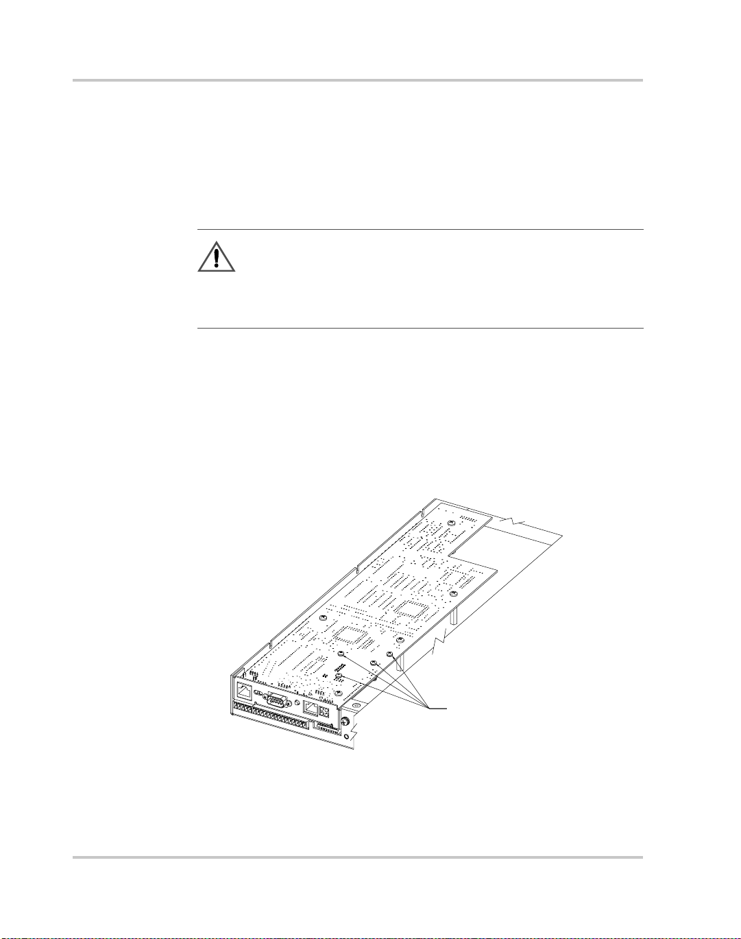
Procedure for 1.2kW XFR
Ensure that the input power connection has been disconnected and the
unit is powe red off before you attempt to remove the top cover. Remove
all the screws holding down the top cover and then remove the cover. The
printed circuit boa rd that you need access to is upside down (component
side down), so you must remove all the screws that a re holding it in place .
Refer to Figure 2-4 to see which screws should not be removed.
During service , do no t
DURING SERVICE, PLEASE DO NOT
REMOVE THESE SCREWS
remove these screws
Figure 2-4
2–8 TM-XR9B-01XN
Removing the PCB
Page 31

Once that is complete, turn the board over and, if necessary, remove the
short ribbon cab le co nn ect ed t o J6 4 on the int erf ace card to ge t acces s to
the under side of the PCB. You can now scan t he board and r efer to Figure
2-3 to locate the various compone nts and jumpers on the PCB. Once you
have made the necessary changes, rec onnect the ribbon cable, screw the
PCB back in place, and screw the top c over on.
Procedure for 2.8kW XFR
Ensure that the input power connection has been disconnected and
the unit is powered off before you attempt to remove the top cover.
Remove all the screws holding down the top cover and then remove
the cover. The printed circuit board that you need access to is right
side up (component side up), so refer to Figure 2-3 to locate the
various components and jumpers on the PCB. Once you have
located the jumpers and made the necessary changes, return the top
cover to its proper position, and screw it back in place.
Changing Internal Jumpers
TM-XR9B-01XN 2–9
Page 32

Installation and Configuration
Basic Setup Procedure - Ethernet
This procedure can be used as a quick reference for those familiar with
the configuration requirements for the Ethernet/R S-232 Interface as
installed in the DC power supply. For those who want more information,
each step refers to more detai led procedures located in subsequent
sections. Execute each step of the procedure in the sequence given.
Table 2-3
Step # Descrip ti on Action Reference
1 Mode
2 Ethernet
3 User Signal
4 Power ON Power on the unit and wait 45
5 L oc at e y o ur
6 Configure the
7 Test Begin Communicating with your
Ethernet Setup Procedure
Configure for Ethernet
Configuration
Connection
Connector
power supply on
your network
Ethernet Bridge
communications.
Connect the CAT 5 network c able to
the Ethernet connector on the
supply.
Configure and use the us er line
connector signals, if required.
seconds for the Ethernet Bridge to
complete its start-up routine. Before
proceeding, chec k to ens ure that the
green NETwork LED on the back
panel is ON.
Load the Setup Software that ships
with this interface card.
Access the device’s web server/
configuration page.
instrument.
See “Configuring for Ethe rnet or RS-
232” on page 2–12.
See “Ethernet Connection” on
page 2–13.
See “User Lines Connector” on
page 2–26.
See “Troubleshooting” on page 3–20
if the NETwork LED does not stay
illuminated after startup has
completed.
See “Locating the Power Supply on
Your Network” on page 2–14.
See “Configuring Ethernet Bridge”
on page 2–15.
If you do not have a TCP/IP based
software application suitable for this
application, and are familiar with RS232 type communica tions, see
“Installing and Using RealPort®” on
page 2–16.
2–10 TM-XR9B-01XN
Page 33

Basic Setup Procedure - RS-232
This procedure can be used as a quick reference for those familiar with
the configuration requirements for the Ethernet/R S-232 Interface as
installed in the DC power supply. For those who want more information,
each step refers to more detai led procedures located in subsequent
sections. Execute each step of the procedure in the sequence given.
Basic Setup Procedure - RS-232
Table 2-4
Step Description Action Reference
1 Mode
2Baud Rate
3 Flow Control
4 Remote/Local
5 RS-232
6 User Signal
7 Power ON Power on the unit. See “Additional User Options and
8 Power Supply
9 Test Test the link by communicati ng with
RS-232 Setup Procedure
Configure for RS-232
Configuration
Selection
Selection
Operation
Connection
Connector
Settings
communications.
Select transmi ssion speed.
(Default 9600)
Select flow control ON or OFF.
(Default is OFF) If flow control is
set ON, choose software-based
XON/XOFF or hardware-based
RTS/CTS communication control.
The factory default is PON REM. See “Remote/Local Operation” on
Connect the RS-232 cable assembly
to the RS232 connector on the
supply.
Configure and use the user line
connector signals, if req u ired.
Configure the controller’s operating
parameters to ma tch the power
supply settings.
the power supply.
See “Configuring for Ethernet or RS-
232” on page 2–12.
See “Baud Rate Se lection” on
page 2–18.
See “Flow Control Selection” on
page 2–19.
page 2–20.
See “Power Supply Settings” on
page 2–23
See “User Lines Connector” on
page 2–26.
Settings” on page 2–24 and “User
Signals” on page 2–26 for
information about Loc al/Remote
OVP, TTL Shutdown, and auxiliary
connecto r user signals .
See “Power Supply Settings” on
page 2–23.
Example: VSET2;ISET1
This co m mand s tr i ng sets po w er
supply voltage to 2V and its current
limit to 1A.
See “Operation”.
TM-XR9B-01XN 2–11
Page 34

Installation and Configuration
Configuring for Ethernet or RS-232
This interface card can be configured for Ethernet communication, or for
RS-232 communication, but not both simultane ously. From the factory,
the instrument wil l be configured for Ethernet communication. Therefore
you should only need to follow these instr uctions if you are switching
over to RS-232, or back to Ethernet. To switch between the two
configuration s, you must change internal jumpers on the interfac e card.
See “Changing Internal Jumpers” on page 2–8. Also refer to Ta ble 2-2
and Figure 2-3 on page 2–6 to locate the corre sponding jumpers.
Table 2-5
Jumper RS-232 Ethernet
J3 1-2 2-3
J4 1-2 2-3
J5 1-2 2-3
J6 1-2 2-3
When you have finished changing the jumper positions, ensure that the
baud rate, flow control, and power-on state are configured properly for
your new setup. These settings are also changed by adding or removing
jumpers, so it is best to perform this adjustment, if necessary, while the
interface card is accessible. Refer to “Baud Rate Selectio n” on page 2–18,
“Flow Control Selection” on page 2–19 and “Remote/Local Mode
Startup” on page 2–20 for m ore detailed information on how to
reconfigure these settings.
Jumper positions for Ethernet or RS-232
Note: If you are switching the interface card back to Ethernet it is
recommended to se t the baud rate to 9600, turn flow control off, and
have the unit power-on in remote m ode (these are the default settings).
2–12 TM-XR9B-01XN
Page 35

Ethernet Communications
Ethernet Connection
There are two options for controlling your XFR power supply via
Ethernet - "Connecting to a Networ k" or "Connecting Directly to your
Computer." The first option is to connect the power supply to a network,
and control the unit from your computer which is also connected to the
network. The second option is to connect the XFR directly to your
computer's network inte rface card (NIC). This bypasses the need for an
existing network.
Connecting to a Network
All that is requir ed to connect your XFR to a network is a straig ht through
CAT 5 network cable and an available network port.
Connecting Directly to your Computer
To connect your XFR directly to your computer you will need a crossover CAT 5 network cable. You will also need to check your network
settings on your computer to ensure that you are using a static IP address.
Check with your IT department for assistance.
Ethernet Communications
TM-XR9B-01XN 2–13
Page 36

Installation and Configuration
Locating the Power Supply on Your Network
1. Record the MAC address for your power supply. This will be visible
at the back of the XFR, on the interface card subplate. For example,
MAC Address
00429D 22EF45
MAC Address:
______________________________
2. Insert the Xantrex XFR Ethernet Software Utilities CD into your CD
drive.
3. If the CD does not start automatically, double-click the My Computer
icon, double-click the CD icon and then double-click
autorun_main.htm.
4. When the menu appe ars, click Xantrex Device Discov ery to instal l
and run the application. This app lication will find and list all XFR’s
with an Ethe rnet/RS-232 Interfa ce card on your ne twork.
5. You can now scan the list and locate your new XFR by its MAC
address.
6. If your network uses a DHCP server and DHCP was enabled on the
XFR, your new inst ru ment will al ready have an IP addr ess. If not, y ou
will have to configure an IP address manually. Refer to steps 2 and 3
in “Configuring Ethernet Bridge” on page 2–15 for more information.
7. Write down the IP address so tha t you can access the instrument via
its web server, and for when you start communi cating with the power
supply.
2–14 TM-XR9B-01XN
Page 37

Configuring Ethernet Bridge
The Ethernet/RS-232 Interface card has an Ethernet Bridge that converts
the ethernet pa ckets to serial data signals for processing by the embedded
microcontroller. The Ethernet Bridge must be properly configured for
serial communicati ons with the microcontroller. For example, settings on
the Bridge, such as Baud Rate and Flow C ontrol, must match the jumper
settings on the interfa ce board.
There are two ways to gain access to the configuration menu for the
Ethernet Bridge. One is to run the Setup program tha t is available on the
Software CD. This program will find your instrument and allow you to
configure it by clickin g on th e instr ument ’ s I P ad dress. You will the n n eed
to enter the correct username and password to be able to configure the
device.
Default Username: root
Default Password: dbps
The other method is to ope n up a web browser like Internet Explorer, and
type in the IP addr ess for the instrument. Again, you will be asked for the
username and password. Once you have accessed the configuration page,
follow these steps for prope r setup.
1. Click Configuration > Serial Port, and ensure that the foll owing
settings have been selec ted:
• Baud Rate: 9600
• Data Bits: 8
• Parity: None
• Stop Bits: 1
• Flow Control: None
Click Apply onc e you have finished a djusting the above settings.
Ethernet Communications
2. Now click Configuration > Network. If your network uses a DHCP
server (ask your IT department) you should se lect Obtain IP addre ss
automatically usi ng DHCP and then click Apply . I f your net work
doesn’t use a DHCP s erver, select Use the following IP address: and
enter an appropriate IP addre ss, Subnet Mask and Default Gateway. .
3. Ask for assistance from your IT depar tment to obta in an appropriate
IP address, Subnet Mask, Default Ga teway, Name Server, a nd
Domain. Once you ha ve made the appr opriate changes, clic k Apply. If
this changed the setting, the device will reboot, so you will have to
renew your connection to its configuration webpage for any further
configuration changes.
TM-XR9B-01XN 2–15
Page 38

Installation and Configuration
Installing and Using RealPort®
Background
RealPort® software allows you to keep using your existing applications
that rely on COM ports and RS-232 links for communication purposes,
instead of ha ving t o de velop TCP/IP based ne twork applic ations. Inst alle d
on a network-enabled PC, RealPort® cre a tes a virtual COM port. As
such, your applica tion still thi nks it is working with a real s erial port, such
as COM1. When the application sends data to this ser ial port, RealPort®
ships the data across the network to the Ethernet Bridge in your power
supply. By doing this, the network is transparent to your existing
application.
Installation
RealPort® can be installed on any PC running Windows NT 4.0,
Windows 2000, or Windows XP.
1. Insert the Xantrex XFR Ethernet Software Utilities CD into your CD
drive
2. If the CD does not start automatically, double-click the My Computer
icon, double-click the CD icon and then double-click
autorun_main.htm.
3. When the menu appe ars, click Digi RealPort ®.
1
4. Follow the on-screen instructions for proper installation.
Note: RealPort® drivers for UNIX syst ems are available . Contac t your
Xantrex representative to obtain these drivers if necessary.
Using RealPort®
Once you have installed the RealPort® driver for your power supply,
using it is as simple as running your existing application (such as
HyperTerminal, or a custom RS-232 application) and setting the COM
port to be the one created by the RealPort® drive r for your instrument.
1.RealPort® is a registered trademark of Digi International.
2–16 TM-XR9B-01XN
Page 39

RS-232 Communications
RS-232 Connection
WARNING
Do not operate the power supply and the computer at
significantly different frame potentials. The interface
connection syste m may not be c apabl e of hand ling the resul ting
excessive ground currents.
Use an approved RS-232 connector and null modem cabl e when
connecting the Ethernet/RS-232 Interface to your computer . The RS-232
connector uses the 9 pin mating connector on the rear panel. Figure 2-5
shows the pinouts for the RS-232 connect or.
Refer to Figure 2-2 on pa ge 2–5 for the position of the RS-232 connector
on the rear panel subplate.
RS-232 Communications
1 NC
2 RXD
3 TXD
4 NC
5 GND
6 NC
7 RTS
8 CTS
9 NC
Figure 2-5 RS-232 Connector Pinouts
TM-XR9B-01XN 2–17
Page 40
Installation and Configuration
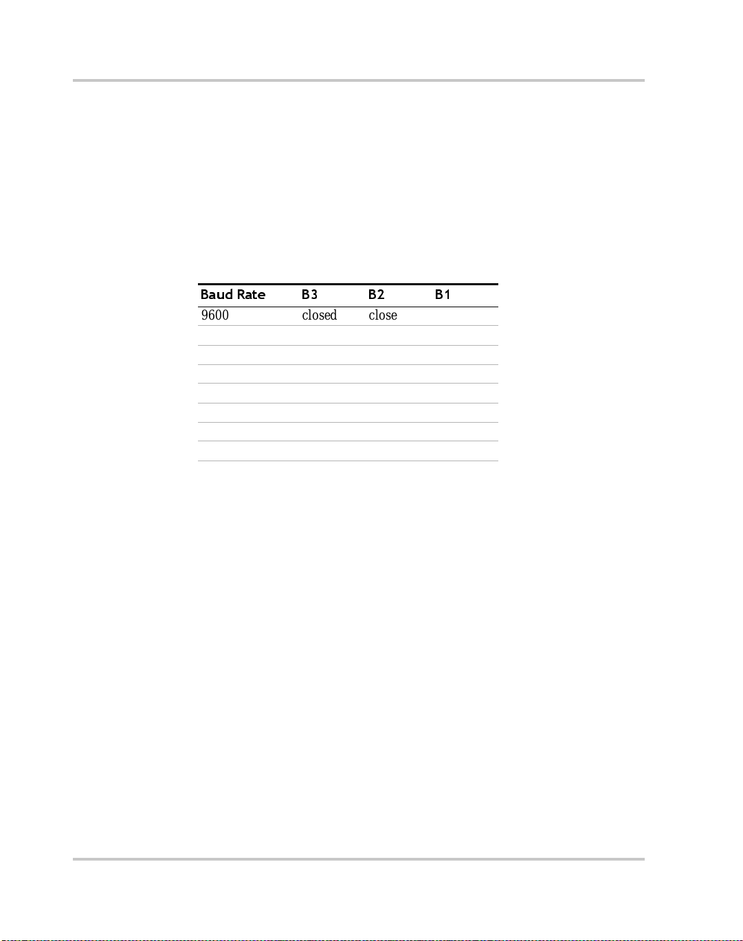
Baud Rate Selection
Serial transmission sends and receives data in bit streams at f ixed bit
rates. Both the computer and the inter face must have the same bit rate
setting for proper communic ation. The default baud rate is 9600. We
recommend that you do not change this setting. If the setting must be
changed, use Table 2-6 to select the correct jumper positions. You will
need to remove the cover to change any jumpers. See “Changing Internal
Jumpers” on page 2–8.
Table 2-6
Baud Rate B3 B2 B1
9600 closed closed closed
4800 open closed closed
2400 closed open closed
1200 open open closed
600 closed closed open
300 open closed open
150 closed open open
75 open open open
Jumper J2 Settings for Baud Rate
2–18 TM-XR9B-01XN
Page 41

Flow Control Selection
Flow control signals regu late data flow for proper communication. To
enable or disable the flow control, change the J2 FLW jumper according
to Table 2-7. With flow control enabled, you can use either software or
hardware pr otoco l s to co n trol fl ow rates. You wi ll ne ed to rem o ve the
cover to change any jumpers. See “Changing In ternal Jumpers” on
page 2–8.
RS-232 Communications
Table 2-7
J2 FLW Jumper Setting C on dit io n
closed (default) Disable Flow Control
open Enable Flow Control
Jumper J2 Flow Control Section
Once flow control is enabled, two flow contr ol methods are available.
You can select software based XON/XOFF flow protocol or hardware
based RTS/CTS by changing an interna l j umper. Table 2-8 shows the flow
control conditions with r egards to the J2 XON jumper.
Table 2-8
J2 XON Jumper Setting Condition
closed (default) Hardware Flow Control
open Software Flow Control
Jumper J2 Flow Control Protocol Selection
(RTS/CTS protoco l)
(XON/XOFF protocol)
TM-XR9B-01XN 2–19
Page 42

Installation and Configuration
Remote/Local Operation
Remote/Local Mode Startup
The power supply can be set to start-up in remote or local mode. To
change this se tting, the PON REM jumper must be adjusted according to
T able 2-9. You will need to remove the cover to change any jumpers. See
“Changing Inte rnal Jumpers” on page 2–8 for information on how t o
change internal jumper se ttings.
See Table 2-9 for the switch settings.
Table 2-9
J2 PON REM Jum per Sett in g Power ON result s
open (default) Unit in remote mode
closed Unit in local mode
With the PON REM jumper open, the power suppl y will start up in
remote mode. The green REM LED on the front panel will be lit,
signaling that the power supply i s under the contr ol of th e digital i nte rface
card. The output of the power sup ply is activ e on start up. To promote load
safety, power ON defaults are zero for the output voltage and current
limit, and 110% of maximum output voltage for the OVP trip point. See
T abl e 2-10. Refer to “Operation” for more infor mation about the inte rface
commands listed in the table.
If the PON REM jumper is closed, the power supply will power up in
local mode. Power supply control is at the front panel. During an
operating sessio n, you can toggle between local mode and remote mode
by using the front panel LOCAL button or sending commands as
described in Table 2-10.
Jumper J2 Remote/Local Start-up Settings.
Note: The default setti ng for thi s jumper is ope n. If you require it to be close d
(PON in local mode) you can obtain a spare jumper by removin g the one that
connects pins 11 and 12 on J2 as these pins are unused.
2–20 TM-XR9B-01XN
Page 43

Remote/Local Operation
Table 2-10
Condition Default Settings 7.5-140 Model Example
Voltage 0 V VSET 0
Current 0 A ISET 0
Soft Voltage Limit VMAX (see models ) VMAX 7.5
Soft Current Limit IMAX (see models) IMAX 140
OVP Trip Voltage Model VMAX + 10% OVSE T 8.25
Delay 0.5 s DLY 0.5S
Remote Enable ON REN ON
Foldback Protection OFF FOLD OFF
Output ON OUT ON
Hold OFF HOLD OFF
Unmask NONE UNMASK NONE
AUXA OFF AUXA OFF
AUXB OFF AUXB OFF
Remote Mode Operation
While in re mote mode, use the interface commands to control the output
of the power su pply from a computer. See “Operation” for a complete list
of device-dependent commands available with this interface.
From remote mode, change to local mode operation by pressing the front
panel LOCAL button or by sending either the GTL command or the
REN OFF command. You can disable the LOCAL button by using the
LLO command. For an example of how to use Local Loc kout, see “Local
Lockout (LLO) Com mand” on page 2–23.
T o retur n to re mote mode, en sure that t he REN command is s et to ON and
then send any valid device-dependent command. Since the remote mode
output setting s may be di ff erent from t he local m ode sett ings, t he output i s
programmed to prote ct the l oad by turni ng of f when you tog gle from loc al
to remote mode during a session. Check your remote settings and the n
send OUT ON to restore the output.
Remote Mode Power On Conditions
TM-XR9B-01XN 2–21
Page 44

Installation and Configuration
Local Mode Operation
In local mode ope ration, you set t he voltage and current output level s a nd
the OVP trip level with controls loc ated on the front panel. Refer to the
operating manual for a description of the functions available at the front
panel.
While in local mode operation, you can change power supply control to
remote mode by ensuring tha t REN is ON, then sending any software
command and OUT ON to restore the output. Return to loc al mode by
pressing the front panel LOCAL button, u nless Loc al Lockout is in ef fe ct.
If LLO is in effect, use the GTL command to send the power supply into
local mode, or use the REN OFF command to turn off LLO and retur n the
power supply to local mode.
Example:
Press the LOCAL button Set unit to local mode
Id? Put the unit into remote mode
Press the LOCAL button
Remote Enable (REN) Command
(Use any command to do this.)
Retu r n to local mod e .
You can use the R emote Enable command to toggle between local mode
and remote mode. The default setting at startup is REN ON. With the
remote enable command set at REN ON, you can return the power supply
to remote mode whenever you send any command from the computer.
Any time that you change from local to remote mode dur ing a se ssion, th e
output is programmed to turn off, since the remote mode settings may be
different f rom the local mode settings. Send the OUT ON command to
restore the output.
You can turn off Remote Enable and move power supply control to the
front panel by sending the REN OFF command. If the Local Lockout
condition is in eff ect, sending the REN OFF command will turn off the
LLO condition be fore sending the unit into local mode.
T o check whether the power supply is remote enabled, use the REN?
query command.
Example:
REN ON Enable the power supply to be sent into
remote mode
VSET 10;ISET 2 Put the unit into remote operation mode
(Use any command to do this.)
2–22 TM-XR9B-01XN
Page 45

Local Lockout (LLO) Command
Use the Local Lockout command to disable the LOCAL button on the
power supply fr ont panel. With LLO in effect, you cannot return to local
control by press ing the front panel LOCAL switch. You can still return to
local mode by sending the Go to Local (G TL) command. However , to turn
off LLO a nd return the power supply to local mode, send the REN OFF
command. Only the REN OFF command will remove the LLO condition.
Example:
LLO Set Local Lockout
GTL Return the power supply to local mode.
REN OFF Turn off Local Lockout and return the
Power Supply Settings
For serial c ommunication, the computer and the Ethernet/RS-232
Interface must share the same communicati on setti ngs. Mak e sure that th e
settings of the computer and of the power supply agree with those shown
in Table 2-11.
Power Supply Settings
Local Lockout is still in effect
power supply to local mode
Table 2-11
Parameter Setting
Transmissi on Asynchronous
Mode Full Duplex
Speeds 75, 150, 300, 600, 1200, 2400, 4800, 9600 (default)
Parity None
Connector DB9-pin Male
Start Bit 1
Stop Bit 1
Data Bits 8
Protocols XON/XOFF
TM-XR9B-01XN 2–23
Power Supply Settings
RTS/CTS
NONE (default)
Page 46

Installation and Configuration
Additional User Options and Settings
You can customize rem ote operation settings for OVP (over voltage
protection) contr ol and TTL shutdown by changing jumper positions on
the Ethernet/RS-232 Interface card. Refer to the operating manual for
information on how to use over voltage pro tection and TTL shutdown.
OVP Selection
Over voltage protection (OVP) on the Ethe rnet/RS-232 Interface is set at
the factory for remote soft ware operation. When operating the power
supply in remote mode, you control the OVP trip level using the OVSET
software command. If you return the power supply to local operation by
using the REN software command or the front panel LOCAL switch,
control of the OVP trip level changes from software control to the front
panel OVP potentiometer . The default OVP trip level is set as 110% of the
power supply's rated outpu t voltage. See Table 2-10 on page 2–21 for a
complete list of remote power ON default settings.
You can isolate the location of OVP control by changing the posit ions of
the Local OVP Control jumper J65 and the Remote OVP Control jumper
J103, both on the Ethernet/RS-232 Interface PCB. The default jumper
settings allow contr ol of OVP to depend on the operating state of the
power supply. By physically ch anging th e jumper sett ings, you can i solate
the location of OVP contr ol to soft ware contr ol on ly or fr ont panel con trol
only. Table 2-12, “OVP Control Mode Selection” on page 2–24 shows a
table of jumper settings and OVP programmin g selection. Refer to Figure
2-3 on page 2–6 for the location of the jumpers on the Ethernet/RS-232
Interface PCB. You will need to remove the cover to change any jumpers.
See “Changing Internal Jumpers” on page 2–8.
Table 2-12
PCB Jumper
J65 Position
Closed (default) Closed (default) Software or Front Panel OVP control
Closed Open Software OVP control only
Open Closed Front Panel OVP control only
Open Open Front Panel OVP contr ol only
2–24 TM-XR9B-01XN
OVP Control Mode Selection
PCB Jump er
J103 Position OV P Programm in g Selecti on
(dependent on the power supply operat ing
state)
Page 47

TTL Shutdown Polarity
You can use the Shutdown function to disable or enable the supply's
output. Disabling the supply using TTL shutdown allows you to make
adjustments to the load or to the power supply without shutting down the
power supply. With the Ethernet/RS-232 Interface installed, TTL
shutdown is ac tivated by a TTL signal to Pin 1 of the user lines connector
on the interface subpla te. The shutdown user line uses a 0-5Vdc TTL
input with a high signal range of 2.2-5. 0Vdc. The current range of the
shutdown line is 1-10mA. See Figure 2-6, “Us er Lines Signal Connector
Circuit Block Diagram” on page 2–27 for a schematic of the user lines
connector contain ing the shutdown user line.
You can select the logic level of the TTL input by changing the J93
connector on the Ethernet/RS-232 Int erface PCB. Table 2-13 shows the
TTL signal levels for the J93 jumper set tings. See Figure 2-3 for the
location of the J93 jumper on the printe d circ uit board. You will need to
remove the cover to change any jumpers. See “Changing Internal
Jumpers” on page 2–8.
Additional User Options and Settings
Table 2-13
PCB Jumper J93 Position TTL Signal Level Supply Output Condition
Pin 2 to Pin 3 (default) HIGH
Pin 1 to Pin 2 HIGH
Jumper Settings for TTL Shutdown Circuit Logic
OFF
LOW
LOW
ON
ON
OFF
TM-XR9B-01XN 2–25
Page 48

Installation and Configuration
User Signals
User Lines Connector
Auxiliary User Lines c onnector, located on the Ethernet/RS-232 Inte rface
rear panel, provides sever al signals to increase your operating control of
the supply. These signals are dependent on the operator's design and uses.
The operation of the user lines connector signal requires that you provide
external Vcc and ground. Use a standard 8-position telephone jack and
data cable to connect to the user lines connector. To locate the connector,
refer to the Ethernet/RS-232 Interface subpla te drawing in Figure 2-2 on
page 2–5. See Table 2-14 for pin descriptions. The user lines connector
outputs can sink a current of 5mA each. Figure 2-6 on page 2–27 shows
the portion of the option board sche matic which contains the user line
connector. Use the schematic as a reference when making input or output
connections.
Table 2-14
Pin Function
1 External TTL shutdown input signal (See “TTL Shutdown
2 Polarity signal, open collector (assert ed by VSET -x)
3 Isolation signal, open collector (asserted by OUT OFF)
4 Fault signal, open collector (asserted wh en bit set in fault register)
5 External Vcc, 15V maximum (supplied by connecting and
6 External ground and shutdown return (supplied by connecting and
7 Open collector user signal (asse rted by AUXA ON)
8 Open collector user signal (asse rted by AUXB ON)
User Signals Connector
Polarity” on page 2–25)
operating an external source)
operating an external source)
User Line
Note: On some models, the
connector is rotated 180°.
2–26 TM-XR9B-01XN
Page 49

User Signals
Figure 2-6
TM-XR9B-01XN 2–27
User Lines Signal Connector Circuit Block Diagram
Page 50

Installation and Configuration
User Lines Cable Connection
Use a standard 8-position telephone jack and data cable to connect to the
user line connector. Add a ferrite block to reduce radiated emission. The
one inch squa re ferrite block with built-in housing clip is packaged and
shipped with the power supply interface card.
To install the ferrite block:
1. Position the block no more than 5 cm (2 in.) from the power supply
end of the user line connector cabl e.
2. Open the ferrite block housi ng.
3. Loop the cable through the ferr ite block. See Figure 2-7, “User Line s
Cable with Ferrite Block” on page 2–28.
4. Close the housing clip.
The ferrite bloc k ens ures tha t the pow er su pply sys tem meets radiat ed
emission requiremen t 89/336/EEC for CE mark approval. See the power
supply's oper ating manual for noise specifications.
Figure 2-7
User Lines Cable
Ferrite Block
To User Cus to m In te r fa ceTo Connector
on XF R
User Lines Cable with Ferrite Block
2–28 TM-XR9B-01XN
Page 51

3
Introduction
Operation
This section covers Ethe rnet /RS-232 Interf ace programming, including
an extensive set of device-dependent commands, er ror codes, and status
and fault register inf ormation.
Page 52

Operation
RS-232 Operation
When the Ethernet/RS-232 Interface ca rd is confi gured for RS-232 you
can send and receive data between your power supply and computer ,
relying on bit serial co mmunication. You can use the computer controller
to issue com mands to the power supply for programming, queries,
calibration, or status. The power supply responds to the complet e
command set of device dependent softwa re commands shown in
“Command Reference” on page 3–9.
Ethernet Operation
When the card is config ured for Ethernet, you can send and receive data
between you power supply and computer via your network. The same
command set is used for RS-232 and Ethernet. The only difference is
medium and protoc ol used.
Command Syntax
Manual Conventions
The manual uses these conventions when displaying command
information. These ch aract ers are not par t of the command but are us ed to
denote parameters used with the command.
< > (angle brackets) Angle brackets enclose a parameter. Do not include
/ (slash) Separates two alternative parameters. When a slash
the angle brackets in the com mand line you se nd to
the computer.
separates two para meters, you can use either
parame ter to achieve the s ame result.
Example:
Entering
<1/ON>
1 or ON will achieve the same result.
3–2 TM-XR9B-01XN
Page 53

Command Format and Parameters
The device-dependent language for the Ethernet/R S- 2 32 In terface
consists of commands and parameter s. A command is a one word code
which either gives instr uctions to the interface or asks for information
from the interface. A command may be followed by one or more
parameters, a short code that changes the state of the power supply or the
state of the bit register. Table 3-1, “Command Parameters” on page 3–4
lists the parameters that affect the command set.
Format:
COMMAND or
COMMAND <parameter> or
COMMAND <parameter>,<pa rame ter>
• You can enter commands in upper or lower case lettering.
Example: MASK FOLD = mask fold
• Do not further abbreviate command names or parameters.
Example: MASK FOLD ≠ MK FOLD
MASK FOLD ≠ MASK FD
• Use a space between the command and the first paramet er. Any
number of consecutive spaces is treated as one space. Numeric data
may contain leading spaces. Embedded spaces between digits or
between a digit and a decimal point are not accepted.
Example: MASK FOLD = MASK FOLD
VOUT 3.4 = VOUT 3.4
VOUT 3.4 ≠ VOUT 3. 4
• Use commas between parameters in those commands with more than
one parameter, and between mnemonic parameters as in the MASK
and UNMASK commands. Only one comma is a ll owed and it may be
preceded or followed by any number of spaces.
Example: MASK CV, OV, FOLD
Command Syntax
TM-XR9B-01XN 3–3
Page 54

Operation
Table 3-1
Parameter Description Form
<current>, <Ihi>, <Ilo> The current in amps or milliam ps. If no unit is given,
<time> The time in seconds or mill is econd s. If no unit is gi ven,
<voltage>, <Vlo>,
<Vhi>
<mnemon i cs> A combination of CV, CC, CV, OV, OT, SD, FOLD,
<state> The state of a binary condition. <1/ON, 0/OFF >
Command Parameters
the default unit is amps.
the default unit is seconds.
The voltage in volts or mil livolts. If no unit is given,
the default unit is volts.
ERR, PON, REM, ACF, OPF, and SNSP. See MASK
and UNMASK commands in the command reference
for use of the ALL and NONE parameters.
<float>
<float>A
<float>mA
<float>
<float>s
<float>ms
<float>
<float>V
<float>mV
See registers on
page 3–17.
Floating Point Number <float>
Variables sent with command parameters are floating point numbers.
T able 3-2 defines the structure of floating point numbers for use with the
software commands.
Table 3-2
Floating Point Numbers
Floating Number Definition Example
The floating point number has four significant figures.
It can be of either sign, positive or negative.
A floating point number can have one decimal point. 0.123
Scientifi c Notation
Use E or e after the number for a base ten exponent.
An integer of either sign must follow an exponent.
3–4 TM-XR9B-01XN
1.234
-1.234
+1.234
1.2
123.4
123.0E-1
1.2E-1
10.00E+1
Page 55

Command Strings
If you send more than one command line, separate the commands with a
semicolon. The semicolon may be preceded or followed by spaces.
Example:
ISET 2.0A; VSET 5V
ISET 2.0A; VSET 5V
Command Terminators
T erminators indicate the end of a command string and tell the power
supply to execute the command. The termination character is CR
(Carriage Return).
Format:
COMMAND <parameter>; COMMAND <parameter>,
<parameter><CR>
Order
You may send commands in any order, keeping in mind that only those
commands received after a HOLD and before a TRG (trigger) will be
released by the TRG command. In addition, only these commands
received after a supply disable (OVP or foldback protection) and before a
RST (reset) or OUT ON command will be released by the RST command
or the OUT command. Commands are executed in the order they are
received.
Command Syntax
TM-XR9B-01XN 3–5
Page 56

Operation
Command Summary
Use these commands to control the operation of the supply. They are
listed here in order of funct ion such as PROGRAMMING, QUERY,
CALIBRATION, and STA TUS commands. See “Command Reference”
on page 3–9 for more detailed information about each command and its
use.
Table 3-3
Command Description
AUXA Selects the state of the AUXA output signal on the Pin 7 of the
AUXB Selects the state of the AUXB output signal on the Pin 8 of the
CLR Initializes the power supply to its Power ON (PON) state.
DLY Sets a programmable ti me delay which is executed by the supply
GTL Sends the supply to local mode.
FOLD Sets foldba ck mode for the supply.
HOLD Enables or disabl es voltage/current setting hold mode for the
IMAX Sets an upper soft limit on th e programmed output current for the
ISET Sets the output current of the supply in amps (default) or in
LLO Local Lockout. Disables the front panel LOCAL button.
OUT Enables or disables voltage/c urrent output for the supply.
OVSET Sets the over voltage protection trip point for the supply in volts
REN Sets remote mode or local mode.
RST Resets the supply to the present voltage and current settings if the
TRG Implements programmed voltage and current settings which had
VMAX Sets an upper soft limit on the supply’s programmed output
VSET Set s the output voltage of t he power supply in volts (de f ault) or in
Programming Commands
user lines connector.
user lines connector.
before reporting fault conditions after a new output voltage or
current is sp ec if ied.
supply.
supply.
milliamps.
(default) or in millivolts.
output is disabled by OVP or foldback protection.
been in hold mode.
voltage.
millivolts.
3–6 TM-XR9B-01XN
Page 57

Command Summary
Table 3-4
Command Description
AUXA? Asks for the state of the set value for the AUXA command
AUXB? Asks for the state of the set value for the AUXB command
CMODE? Asks for the power supply’s c alibration mode status.
DLY? Asks for the programmable time delay se tting before the supply
ERR? Asks for the most recent remote programming error which
FOLD? Asks for the supply’s present foldback setting.
HOLD? Asks for the present hold mode setting.
ID? A s ks for the power supply’s model name and master EPROM
IMAX? Asks for the supply’s soft current limit setting.
IOUT? Measures the supply’s actual current output.
ISET? Asks for the supply’s present output current limi t se tting.
OUT? Asks for the present enabled/disable d status of the supply’s
OVSET? Asks for the supply’s present over voltage protection limit.
REN? Asks for the state of remote enable.
ROM? Asks for the ve rsion number of the master and slave EPROMs on
VMAX? Asks for the supply’s soft voltage limit setting.
VOUT? Measures the supply’s actual voltage output.
VSET? Asks for the supply’s present output vol tage setting.
Query Commands
reports fault conditions.
occurred in the supply since the last time the error query
command (ERR?) was us ed.
version.
output.
the interfac e PCB.
TM-XR9B-01XN 3–7
Page 58

Operation
Table 3-5
Command Description
CMODE Places the supply into calibration mode.
IDATA Calculates the slope and intercept for current programming.
IHI Sets the current output to the high calibration point.
ILO Sets the current output to the low calibration point.
IRDAT Calculates the slope and intercept for current readback.
IRHI Sets the current output to the high readba ck point.
IRLO Sets the current output to the low re adback point.
OVCAL Calibrates the over vol tage protection (OVP).
VDATA Calcula tes the slope and intercept for voltage programming.
VHI Sets the voltag e output to the high calibration point.
VLO Sets the voltage outpu t to the low calibration point.
VRDAT Calculates the slope and intercept for voltage readback.
VRHI Sets the voltage output to the high readback point.
VRLO Sets the volt age output to the low readback point.
Table 3-6
Command Description
ASTS? Asks for the supply’s accumulated status register.
FAULT? Asks for the supply’s fault register for the status preset opera ting
MASK Prevents the supply's previously unmasked operating conditions
STS? Asks for the supply’s present status regi s ter.
UNMASK Enables you to select those supply's operating conditions t hat you
UNMASK? Asks for the supply's fault conditions which are currently ena bled
Calibration Commands
Status Commands
conditions.
from setting bits in the fault register.
are most interested in monitoring for fault occurrence.
(unmasked).
3–8 TM-XR9B-01XN
Page 59

Command Reference
Command Reference
Table 3-7
Command Description
ASTS? Asks for the supply’s accumulated status register. The accumulated status registe r
AUXA <1/ON>,
<0/OFF>
AUXA? Asks for the present set value of the AUXA output s ignal.
AUXB <1/ON>,
<0/OFF>
AUXB? Asks for the present set value of the AUXB output signal.
CLR Initializes the power supply to its power ON condi tion. If issued while in local
Command Reference
stores an y bit th at was ent er ed in the st at u s regi s t er sin c e th e accumul ated statu s
query command (ASTS?) was last used, reg ardless of whether the condition still
exists. The accumulated status register has the same bits, weights, and condi tions
as the status register. A bit in the accumulated status register will be set at 1 if the
corresponding bit in the status register has been 1 (TRUE) at any time since the
register was last read . See “Accumulated Status, Status, and Fault Registe r s” on
page 3–17. The ASTS? query clears the st atus register.
Response: ASTS <statu s mask> whe re stat us mask is the decima l equiva le nt of the
total bit weight s for th e operating conditions as listed in the status register.
Controls the AUXA output signal level at rear panel connector Pin 7. Acti ve low.
Initial value: AUXA 0
Response: AUXA 0 (OFF) or AUXA 1 (ON)
Controls the AUXB output signal le vel at rear panel connector Pin 8. Active low.
Initial value: AUXB 0
Response: AUXB 0 (OFF) or AUXB 1 (ON)
mode, CLR will force power supp ly settings to register default va lues as in but
these defa ult sett ing s will not com e in to ef f ect unti l t he po wer supp ly i s swi tch ed to
remote mode operation. The CLR commands will clear faults from the fault
register. CLR will not reset CMODE.
CMODE <1/ON>,
<0/OFF>
CMODE? Asks for the power supply’s calibration mode status .
TM-XR9B-01XN 3–9
CMODE ON places the power supply into calibration mode for proc essing
calibration commands.
Initial value: CMODE OFF or CMODE 0
Res p on s e : CMOD E 0 ( d is able d )
CMODE 1 (enabled)
Page 60

Operation
Table 3-7
Command Description
DLY <seconds> Sets a programmable time delay employed by the supply before reporting fault
DLY? Asks for the setting of the programmable time delay be fore the supply reports fault
ERR? Asks for the most recent remote programming error. When the power supply
FAULT? Asks for the state of the f ault register. A bit is set in the f ault register when a fault
Command Reference
conditions. The power s upply uses the time delay aft er re ceiving a new output
voltage or current s etting via VSET or ISET, or after receiving RST, TRG, or OUT
ON commands. During the time delay, the power supply disables CV, CC, and
FOLD conditions from generating faults, preventing possible nuisance foldback if
the supply momentarily switches modes while changing an output setting.
Range: 0 to 32 seconds, with 32ms resolution
Initial va lue: 0.5 second
conditions.
Response: DLY <seconds>
detects a programmi ng error, it lights the ERR LED and sets the ERR bit in the
accumulated status and fa ult registers. I f the error bit has been masked using the
MASK command, then the ERR bit in the registers will not set. Once an err or is
detected, the remaining portion of the command line is discarded. An error que ry
clears the ERR bit in the accumulated status register. See “Error Codes” on page 3–
19.
Response: ERR <error number> Example: ERR 0 (if no error)
arises for that condition. Lists the conditions which activate a fault bit . You can use
the MASK command to disable bits from being set in the fault register.
When a bit is set in the fault register it also asserts a signal on the Pin 4 user signal
line. You can tie the Pin 4 fault line signal to the power supply's own External
Shutdown user line, Pin 1, so that the shutdown s ignal goes low (active) in the case
of a user-defined fa u l t.
The FAULT? query clears bits in the supply's fault register and fault line.
Response: FAULT <fault mask> where fault mask is the decimal equivalent of the
total bit weight s for th e operating conditions as listed in the fault register. See
“Accumulated Status, Stat us, and Fault Registers” on page 3–17.
FOLD
<2/CC>, <1 /CV>,
<0/OFF>
3–10 TM-XR9B-01XN
Sets foldback mode for the su pply. Foldback protection disables the power supply
output when the output enters the fold condition. Reset with the RST command.
Example: Specify FOLD 1 or FOLD CV (Constant Vol tage) when you want the
supply to operate in Cons tant Current mode and have foldback protecti on disable
the output if the supply swit ches to Constant Voltage mode.
Initial value: FOLD 0/OFF
Page 61

Command Reference
Table 3-7
Command Description
FOLD? Asks for the supply’ s pres ent foldback setting.
GTL Go to local. Returns the power supply to local cont rol. See LLO (Local Lockout).
HOLD <1/ON>,
<0/OFF>
HOLD? Asks for the present hold mode setting.
ID? Asks for the power supply model and the mast er E PR OM vers ion.
IDATA
<Ilo>,<Ihi>
Command Reference
Response: FOLD <mode> whe r e mode is :
0 (OFF) or
1 (CV or Constant Voltage mode) or
2 (CC or Constant Current mode)
See also “Remote/Local Operation” on page 2–20.
Enables or disables voltage/current setting hold mode for the supply. When
HOLD ON is specified, hol d mode is enabled so that all voltage and current
settings which would normally be implemente d by the supply are held until a TRG
(trigger) command is recei ved. This feature all ows you to sy nchronize the
operation of several su pplies.
Initial value : HOLD OFF or HOLD 0
Response: HOLD 0 (OFF or disabled) or HOLD 1 (ON or enabled)
Response: ID <model name>< vers ion>
Calculates and records the slope and offset for programmed current using ILO and
IHI data. Set CMODE ON before using th is command. See also the cali bration
procedures in Chapter 4.
<Ilo> and <Ihi> are in <curre n t > format.
IHI In response to this command, the power supply sends a programmed current value
to the output terminal. This value is at the high end of the power supply’s current
range an d i s read by an ex ternal device connected as part of the calibration
procedure. Refer to this value as IHI and re cord it to use a s input with the IDATA
command. Set CMODE ON before usin g this command. See also the cal ibration
procedures in Chapter 4.
ILO In response to this command, the power supply sen ds a programmed current value
to the output terminal. This value is at the low end of the power supply’s current
range an d i s read by an ex ternal device connected as part of the calibration
procedure. Refer to this value as ILO and record it to use as input with the IDATA
command. Set CMODE ON before usin g this command. See also the cal ibration
procedures in Chapter 4 .
TM-XR9B-01XN 3–11
Page 62

Operation
Table 3-7
Command Description
IMAX <current> Sets an upper soft l imit o n the supply’s programmed output c urrent. If the so ft limi t
IMAX? Asks for the supply’s soft current limit setting.
IOUT? Measures the supply’s actual current output using the built-in current readback
IRDAT
<Ilo>,<Ihi>
IRHI The powe r suppl y output s a current va lu e to an external d evice connecte d as p art of
Command Reference
is exceeded, or if the soft limit val ue is lower than the present output current
setting, the supply will ignore the command, turn on the ERR LED, and set the
ERR bit in the bit registers.
Rang e: 0 to mo del ma x imum output cur re n t ( IMAX )
Initial value: model IMAX
Response: IMAX <current>
circuitry.
Response : IOU T <c urre n t>
Calculates and records the slope and offset for rea dback voltage using IRLO and
IRHI data. Set CMODE ON before using this comma nd. See also the calibration
procedures in Chapter 4.
<Ilo> and <Ihi> are in <curre n t > format.
the calibration proced u re and records a current readback value internally. These
values are at the high end of the programmed current range. Refe r to the output
value as IRHI and record it to use as input with the IRDAT command. Set
CMODE ON before using this command. See also the calibration procedures in
Chapter 4.
IRLO The power supply outputs a curre nt valu e t o an ext ernal d evice co nnecte d as part of
the calibration proced u re and records a current readback value internally. These
values are at the low end of the programmed current range. Refer to the output
value as IRLO and reco r d it to use as input with the IRDAT co mm and. Set
CMODE ON before using this command. See also the calibration procedures in
Chapter 4.
ISET <current> Sets the power supply’s output current in amps (default) or in milliamps. This
programmed current is the actual output in CC mode or the cu rrent limit in CV
mode.
Rang e: 0 to mo del ma x imum output cur re n t ( IMAX )
Initial value: 0 amps
ISET? Asks for the supply’s pres ent output current setting. Does not apply to curre nt
settings which ar e being held. See HOLD command.
Response: ISET <current>
3–12 TM-XR9B-01XN
Page 63

Command Reference
Table 3-7
Command Description
LLO D is ables the front panel LOCAL switch. When LLO is in effect you can only
MASK
<mnemonics>
OUT <1/ON>, <0/
OFF>
OUT? Asks for the present enabled/disa bled status of the supply’s out put voltage/current.
Command Reference
return to local mode using the GTL command. You can remov e the local lockout
with the REN command. See also “Remote/Local Operation” on page 2–20.
Disables the supply's previously unmasked operating conditions from setting bits
in the fault and status regis ters. See “Accumulated S tatus, Status, and Fault
Registers” on pag e 3–17. Mnemonics are separated from each other by commas
and may be sent in any order.
Mnemonics: CV, CC, OV, OT, SD, FOLD, ERR, PON, REM, A CF, OPF, SNSP
Note: UNMASK NONE = MASK ALL (Initial value)
MASK NONE = UNMASK ALL
Enables or dis able s the supp ly’s voltage/current out put. T he s upply wil l c ontinu e t o
accept new com mands while the output is disabled but these will not be
implemented until OUTON or OUT 1 is received. OUT ON is the default settin g.
When you start the supply in remote mode, the output is enabled.
OUT OFF (or OUT 0) also sets the isolation signal on the rear pane l user lines
connector , line3. Y ou can us e the to tri p extern al relays to isola te the power su pply
from th e load.
Initial value: OUT ON (or OUT 1) for output enabled
Response: OUT 1 output enabled or
OUT 0 output disabled
OVCAL Causes the master control ler to perform automatic calibra tion of the supply’s over
voltage prote ction circuitry. Set CMODE ON before using this comm and. Ensure
jumper J65 on the E thernet/RS-232 Interface PCB is connected for rem o te
operation.
OVSET
<voltage>
OVSET? Asks for the supply’s present over voltage protect ion limit.
TM-XR9B-01XN 3–13
Sets the supply’s over voltage protecti on trip point in volts (default) or in
millivolts. If the trip point is exceeded, or if the trip point value is lower than the
present output voltage setting, the supply will ignore the command, turn on the
ERR LED, and set the ERR bit in the accumulated status register. Reset with the
RST command.
Range: 0 to 110% of model maximum output voltage (VMAX)
Initial value: 110% of model VMAX
Response: OVSET <voltage>
Page 64

Operation
Table 3-7
Command Description
REN <1/ON>, <0/
OFF>
REN? Asks for the state of the remote ena b le. See REN command.
ROM? Asks for the version number of the master and slave EPROMs located on the
RST Resets the supply to present volt age and c urrent s etti ngs if the outp ut is di sabl ed by
STS? Asks for the supply’s present status regi ster. Status conditions are stored in the
Command Reference
Remote Enable. When set to REN 0, the power supply is in local mode. If a
command is sent from the computer, the power supply does not respond but
remains in local mode. When set to REN 1, the power supply will enter remote
mode if a command is sent from th e computer. See also “Remote/Local Operation”
on page 2–20.
Response: R EN <st ate>
interf ace PCB.
Response: RO M M: <ve rs ion> S:<v ersi on >
over voltage or foldback protection. Output values may be changed via VSET,
ISET, and OVSET while the unit is disabled, but those values will not take effect
until RST is applied.
status register. Each bit represents a separate condition. When the condition is true,
the corresponding bit is 1 (true). Bits remain set in the status register as long as the
condition is tr ue. S ee “Accumulated Status, Status , and Fault Registers” on page 3–
17.
Response: STS <status ma sk > whe re stat us mask is the decim al equi val ent of the
total bit weight s for th e operating conditions as listed in the status register.
TRG Implements programmed voltage and current settings which had been in hold
mode. The supply operates with previous values until the TRG (trigger) command
is sent.
UNMASK
<mnemonics>
3–14 TM-XR9B-01XN
Enables you to selec t the supply operating c onditions that you are most interested
in monitoring for fault occurrence . Mnemonics describing the conditions are
separated from each other by commas, and may be sent in any ord er.
Specifying one or more mnemonics which describe the conditions (or the decimal
equivalent of their total bit weight) enables the selected conditions to se t bits in the
supply’s fault and status registers during operation. A bit is set in the fault register
when the corresponding bit in the status register changes fr o m 0 to 1 and the
corresponding bit in the mask register is1. See “Accumulated St atus, Status, and
Fault Registe r s ” on page 3–17.
Mnemonics:CV, CC, OV, OT, SD, FOLD, ERR, PON, REM, ACF, OPF, SNSP,
ALL, NONE
Initial value :UNMASK NONE
Page 65

Command Reference
Table 3-7
Command Description
UNMASK? Asks for the supply's fault conditions which are currently enabled (unmasked).
VDATA
<Vlo>,<Vhi>
VHI In response to this comm and, the power supply sends a programmed voltage value
VLO In resp onse to this command, the power supply sends a programmed voltage value
Command Reference
Response: UNMASK <fault mask> where fault mask is the deci mal equivalent of
the total bit weights for the operating conditions as listed in the status and fault
registers See “Accumulated Status, Status, and Fault Registers” on page 3–17.
Calculates and records the slope and offset for program med voltage using VLO
and VHI data. Set CMODE ON before using this command. See also the
calibration procedures in Chapter 4.
<Vlo> and <Vhi> are in <voltage> format.
to the output termi nal. This value is at the high end of the power supply’s voltage
range an d i s read by an ex ternal device connected as part of the calibration
procedu re. Refe r to thi s valu e as V HI and r eco rd i t to us e as in p ut wit h the VDATA
command. Set CMODE ON before usin g this command. See also the cal ibration
procedures in Chapter 4.
to the output terminal. This value is at the low end of the power supply’s voltage
range an d i s read by an ex ternal voltmete r co nnected as part of the calibration
procedure. Refer to thi s value as VLO and record it to use as input with the
VDATA command. Set CMODE ON before using this command. See also the
calibration procedures in Chapter 4.
VMAX <voltage> Sets an upper soft l imit on t he supply ’ s pro grammed o utput vol tage . If the s oft li mit
is exceeded, or if the soft limit value is lower than the present output voltage
setting, the supply will ignore the command, turn on the ERR LED, and set the
ERR bit in th e accumulated status register.
Range: 0 to model maximum output voltage (VMAX)
Initial value: model VMAX
VMAX? Asks for the supply’s soft voltage limit setting.
Response: VMAX <voltage>
VOUT? Measures the supply’s actual voltage output using the built-in voltage readback
circuitry.
Response: VOUT <voltage>
VRDAT
<Vlo>,<Vhi>
TM-XR9B-01XN 3–15
Calculates and reco rds the slope and offset for rea dback voltage using VRLO and
VRHI data. Set CMODE ON before using this command. See also the ca libration
procedures in Chapter 4 .
<Vlo> and <Vhi> are in <voltage> format.
Page 66

Operation
Table 3-7
Command Description
VRHI The power supply outputs a voltage value to an external voltmeter connected as
VRLO The power supply outputs a voltage value to an ext ernal voltmeter connected as
VSET <voltage>
or
VSET <-voltage>
Command Reference
part of the calibration procedure an d records a voltag e readback value internally.
These values are at the hi gh end of the programmed voltage range. Refer to the
output value a s VRHI and record it to use as input with the VRDAT command. Set
CMODE ON before using this command. See also the calibration procedures in
Chapter 4.
part of the calibration procedure an d records a voltag e readback value internally.
These values are at the low end of the programmed voltage range. Refer to the
output value as VRL O and reco rd it to us e as input with t he VRDAT command. Set
CMODE ON before using this command. See also the calibration procedures in
Chapter 4.
Sets the power supply’s output voltage in volts (default) or in millivolts. Thi s
programmed voltage is the actual output in CV (constant voltage) mode or the
voltage li mit in CC (constant current) mode.
If you enter a negative voltage value , the power sup ply will ass ert a signal on Pin 4
of the user signal line. You can use the use r signal to trip external relays to switch
the output polarity.
Rang e: 0 to mo del ma x imum output vol ta ge (VMAX)
Initial va lue: 0 volts
VSET? Asks for the power supply’s present output voltage sett ing. Does not apply to
voltage settings which are being held. See HOLD command.
Response: VSET <voltage>
3–16 TM-XR9B-01XN
Page 67

Accumulated Status, Status, and Fault Registers
Accumulated Status, Status, and Fault Registers
The Ethernet/RS-232 Interface card uses three separate registers which
are always active. They are the accumulated status, status, and fault
registers. You can use the status commands shown in Table 3-6, “Status
Commands” on page 3–8 to activate the registers. The bit register has
twelve conditions, each assigned a bit weight. When querying a registe r,
the controller returns a response which is the sum of the weights of all
relevant conditions.
Example:
ASTS? Query the Accumulated Status register.
ASTS 771 Controller response.
771 = 512 + 256 + 2 + 1 = PON + REM + CC + CV
The accumulated sta tus register shows that PON, REM, CC and CV have
all been active since the last accumu l ated statu s regist er q uery.
T able 3-8 shows the m nemoni cs and bi t we ights whi ch correspond to each
register condition. You can select conditions you want to monitor in the
fault and status regis ter by using the MASK and UNMASK commands.
TM-XR9B-01XN 3–17
Page 68

Operation
Table 3-8
Condition Mnemonic
Accumulated Status, Status and Fault Registers
Bit
Position
Bit
Weight
Constant voltage operation CV 0 1
Constant current operation CC 1 2
Not used – 2 4
Overvoltage prote ction tripped OV 3 8
Over temperature prot ection tripped OT 4 16
Supply external shutdown active Pin 1 of the
SD 5 32
user lines connector
Foldback mode operation FOLD 6 64
Remote programming error E RR 7 128
Power ON
PON 8 256
(accumulated status, status regist ers only)
Remote mode
REM 9 512
(accumulated status, status regist ers only)
AC fail condition ACF 10 1024
Output fail condition OPF 11 2048
Sense protec tion tripped SNSP 12 4096
Notes:
1. All mnemonics can be mas ked or unmasked.
2. The error (ERR) bit is reset in the accumulated stat us, status, and serial poll registers
with an error que ry (ERR ?) .
3. The accumulated stat us regi st er is cl ea red wit h an ac cumul ated s tat us qu ery (ASTS ?) .
4. A fault is cleared wi th a fault query (FAULT?).
3–18 TM-XR9B-01XN
Page 69

Error Codes
Error Codes
If the ERR flag in the accumulated status or fault registers has been
activated, an ERR? query will return an error number which corresponds
to an event described in the following table. The ERR? query will also
clear the ERR bit in the reg ister.
Table 3-9
Error # Error Identification Explanation
0No Errors
4 Unrecognized Character Received a character such as @,*,$.
5 Number Out of Range Specified a va lue for the command which
6 Attempt to Ex ce ed S o ft
7 Improp er Soft Limit Attempted to program a soft limit less
8 Data Requested without a
9 OVP Set Below Outpu t Sent an OVSET command with a trip
10 Sl av e P ro cessor Not
12 Illegal Calibration Attempted calibration when the supply
Error Codes
Improper Number Rece iv ed a numeric character but the
characters wer e not a pro per num ber.
Example: VSET,±10.3
Unrecognized S tring Received an invalid command.
Syntax Error Rece iv ed an incorrectly placed word,
number, separator, or terminator.
Example: OFF SRQ, VOUT 6, MASK,
ERR
was outside of the allowed range.
Attempted to program a volt age or
Limits
Query Being Sent
Responding
current greater than the soft limit.
Example: VMAX 500; VSET 550 L F
than the output value.
The controller requested data from the
power supply without first sending a
query command.
value lower than the output voltage.
The interface PCB slave processor did
not respond.
was not in calibrat ion m ode. See
CMODE command.
TM-XR9B-01XN 3–19
Page 70

Operation
Troubleshooting
WARNING
Exercise caution when using and servic ing power supplies.
High energy le vels can be stored at the output volta ge te rminals
on all power supplies in normal operation. In addition,
potentially letha l voltages exist in the power circuit and the
output connector of power supplies which are rated at 40V and
over. Filter c apacitors store potentially dangerous energy for
some time after power is removed.
Diagnostic LEDs
This section desc ribes the di agnostic LEDs found on th e Ethernet/RS-232
Interface.
Computer Operating Properly (COP) LEDs
The Et hernet/R S-232 I nterfa ce prov ides thre e dia gnostic LEDs, loc ate d at
CR167, CR166, and CR89 on its PCB. Refer to Figure 2-3, “Ethernet/RS-
232 Interface PCB” on page 2–6, for their locations. At present, these
LEDs turn on to signal COP events for the interface' s microprocessors.
Issue a RST (reset) command to turn off the diagnostic LEDs.
The green COP LED at circuit designation CR167 indicates that the
Ethernet/ RS -2 32 Int erf ace microprocessor successfully recovered from a
timeout error due to a communications bus error. The event is transparent
to the RS-232 communic ations line which continues to function normally.
The red COP LED at CR166 indicates that a transpare nt restart caused by
noise in the master p ro cess o r circu i try has occu rr ed .
The red COP LED at CR89 indicates that a transparent restart caused by
noise in the slave pro ces so r ci rcui t ry has o ccurred.
3–20 TM-XR9B-01XN
Page 71

Ethernet Mode Troubleshooting Tips
Troubleshooting
Table 3-10
Sympto m Possible Causes Corrective Act io ns
Cannot establish
communication or
cannot find XFR on
network using the
setup program from
the CD
Ethernet Mode Tips
Instrument is not prop erly
connected to the network
Check the four Ethernet LEDs at the back of the
XFR. If the green Network LED is NOT
permanently illuminated, check the connection.
Ensure that the Ethernet cable is securely
connected to the RJ45 Ethernet connector and
not to the User Line (User Int) connector.
Ensure that the network drop is live - check with
your IT department for assistance with this.
If you are connecting the in strument to a
network hub, ensure that you are us ing a
straight-through CAT5 network cable.
If you are connecting the in strument directly to
your computer, ensure that you are using a crossover CAT5 network ca ble. You also need to
ensure that the netwo r k settings on your
computer have been changed so that your
computer uses a static I P address .
If the problem persists, press the Ethernet Reset
button (SW1) on the back panel and wait 45
seconds to see if the Green N etwork LED
illuminates permanently.
Trying to connect to the
wrong IP address
Not waiting long enough
after turn ing the power on,
or resetting the Ethernet
Bridge
TM-XR9B-01XN 3–21
Use the Support software that came with your
power supply to find the inst rument on your
network. If it is properly connected to the
network, the Device Discovery program will
locate the unit and display its IP address.
Wait 30-45 seconds at power on to al low the
Ethernet Bridge to complete its start-up routine.
Page 72

Operation
Table 3-10
Sympto m Possible Causes Corrective Act io ns
Able to connec t to
the device server
(Ethernet Bridge),
but unable to
control or rec eive a
response from the
power supply
Ethernet Mode Tips
The Ethernet/RS-232
Interface card is configured
for RS-232 communicati ons
The em be d de d Eth e rn e t
Bridge is inc or r ectly
configured
Reconfigure the interface card for Ethernet
communication s. See page 2–12 for details.
Ensure that the baud rate for the Etherne t Brid ge
is set for 9600 by connecting to its HTTP server
and che ck ing i ts Ser ial P ort setti ngs. This can be
done by entering the device's IP address into a
web browser and usi ng the c orrect u sername an d
password to access the device server. See
“Configuring Etherne t Bridg e” on page 2–15 for
more information.
Ensure that the baud rate setting on the interface
card is set to 9600 - see the “Baud Rate
Selection” on pag e 2–18 for details.
3–22 TM-XR9B-01XN
Page 73

RS-232 Mode Troubleshooting Tips
Troubleshooting
Table 3-11
Sympto m Possible Causes Corrective Act io ns
Cannot establish
communication
RS-232 Mode Tips
Using straight through
RS-232 cable instead of
Null Modem ca ble
Loos e ca bl e s
Baud rate mismatch
Trying to communicate via
the wrong COM port
The interface card is
configured for Ethernet
communications
Use a Nul l M od em ca b le
Ensure that the cables are securely connected to
the computer and the power supply.
Select a baud rate that matches the instruments
settings. See “Bau d R a t e Se l e c t i o n” on page 2–
18 for de tails on changing this setting.
Most computers have two COM ports, COM1
and CO M 2 , so en su r e you have selected th e
correc t CO M p ort.
Reconfigure the interface card for RS-23 2
communication s. See “Configuring for Ethernet
or RS-232” on page 2–12 for details.
RS-232 and/or Ethernet Mode Troubleshooting Tips
Table 3-12
Sympto m Possible Causes Corrective Act io ns
Instrument not
responding to new
user settings
The outp ut is
displaying zero
volts and zero amps,
but the set points are
non-zero
TM-XR9B-01XN 3–23
RS-232 and/or Ethernet Mode Tips
The unit is in local mode Put the unit into remote mode by sending the
The outp ut is of f
The output has tripped due
to an OVP, or foldback
protection event
command REN ON.
Send the command OUT ON
Correct the condition that has caused the fault,
and send the command RST
Page 74

3–24
Page 75

4
Introduction
Calibration
WARNING
Exercise caution when using and servic ing power supplies.
High energy le vels can be stored at the output volta ge te rminals
on all power supplies in normal operation. In addition,
potentially letha l voltages exist in the power circuit and the
output connector of power supplies which are rated at 40V and
over. Filter c apacitors store potentially dangerous energy for
some time after power is removed.
You can calibrate the interface in either Ethernet or RS-232 mode by
adjusting the signal le vels on the interface card so that they corres pond
to the expected signal leve ls on the power supply's main assembly. Y ou
may need to recalibrate the interface if you replace parts either on the
interface board or on the main power supply board, or if the unit falls
out of specificati on due to component aging drifts.
Page 76

Calibration
You can calibrate the Ethernet/RS-232 Inte rface for:
• Voltage program
• Voltage readback
• Current program
• Current readback
• Overvoltage protection
The following equipment will be required to accurately calibrate your
unit:
• Digital Voltmeter, 5 1/2 digit, 0.1% accuracy or better, with test leads
• Current sensing shunt resistor, rated for 150% of maximum output
current, 0.25% accura cy or better
• Connection wires rated for the unit's maximum output current and
voltage
• A network ready, or RS-232 equipped computer to send the
calibration commands to the unit
Calibrate the unit accor ding to the following procedures, referring to
“Command Reference” for more information about the calibration
commands used.
The calibration procedures in this section ar e designed to be p erf ormed at
an ambient temperature of 25°C ± 5°C.
4–2 TM-XR9B-01XN
Page 77

Voltage Mode Calibration
Voltage Calibration Setup
1. Disconnect the load from the power supply whic h is to be cal ibrated.
2. Connect a voltmeter across the power supply’s output terminals.
Voltage Mode Calibration
Power Supply
Positive Output
+
VOLTMETER
Figure 4-1
Voltage Calibration Setup
Voltage Program Calibration Procedure
1. Set the power supply for calibration as in Figure 4-1.
2. Activate calibr ation mode by sending command CMODE ON or
CMODE 1 to the power supply.
3. Send command VLO; ILO to the power supply. Measure and record
the output shown on the external voltm eter.
4. Send command VHI; I HI to the supply. Measure and record the
output voltage as shown on the externa l voltmeter.
5. Send the command VDATA <vlo>,<vhi> where <vlo> and <vhi> are
the values read fro m the volt me t er w hen the VL O and VH I
commands were sent. Whe n the powe r supp ly is calibrate d, the low to
high voltage program calibration values are stored as constants.
Power Supply
Negative Output
V
-
6. Program the supply at various levels using the VSET com mand to
confirm that the calibration was successful and that linearity is
observed. See the voltage program accuracy specification in
Appendix A.
7. Turn off calibration mode by sending the command CMODE OFF or
CMODE 0 to the power supply.
TM-XR9B-01XN 4–3
Page 78

Calibration
Voltage Readback Calibration Procedure
1. Set the power supply for calibration as in Figure 4-1.
2. Activate calibr ation mode by sending command CMODE ON or
CMODE 1 to the power supply.
3. Send command VRLO; IRLO to the power supply. Wait for the
supply to s ettle. Measure and record the output shown on the external
voltmeter. Send VRLO ag ain .
4. Send VRHI; IRHI to the supply. Wait for the supply to settle.
Measure and record the output voltage shown on the e xternal
voltmeter. Send VRHI agai n.
5. Send the command VRDAT <vlo>,<vhi> where <vlo> and <vhi> are
the values read from the voltmeter after the VRLO and VRHI
commands were sent. The processor cal culates the offset val ue
required to calibra te the power supply. When the power supply is
calibrated, the low to high voltage readback calibr ation values
(offsets) are stored as cons tan t s.
6. Use commands VSET and VOUT? commands to confirm that the
calibration was successful a nd that linearity is observed. Refer to the
voltage read back acc u racy spe cifi cat io n in Appendix A.
7. Turn off calibration mode by sending the command CMODE OFF or
CMODE 0 to the power supply.
4–4 TM-XR9B-01XN
Page 79

Current Mode Calibration
Current Calibration Setup
1. Disconnect the load from the power supply to be calibrated.
2. Connect a shunt across the supply's output terminals.
3. Connect a voltmeter across the shunt.
Current Mode Calibration
Power Supply
Positive Output
Curr en t Se nsi ng
+
VOLTMETER
Figure 4-2
Current Calibration Setup
Current Program Calibration Procedure
1. Connect the shunt and voltme ter to the power supply as shown in
Figure 4-2.
2. Activate calibr ation mode by sending command CMODE ON or
CMODE 1 to the power supply.
3. Send command ILO; VLO to the power supply. Measure and record
the output shown on the external voltm eter.
4. Send command IHI; VHI to the supp ly Measur e and r ecord the outpu t
voltage shown on the external voltm eter.
5. Calculate ILO and IHI from the voltages read from the external
voltmeter and the shunt resistance. I=V/R.
6. Send the command IDATA <ilo>,<ihi> to the power supply. <ilo>
and <ihi> are the current valu es obtained from sending the ILO and
IHI commands to the power supply. When the power supply is
calibrated, the low to high current program calibration values are
stored as constants.
Resistor
V
Power Supply
Negative Output
-
TM-XR9B-01XN 4–5
Page 80

Calibration
7. Program the supply at various levels using the ISET command to
confirm that the calibration was successful and that linearity is
observed. Refer to the current program accuracy specification in
Appendix A.
8. Turn off calibration mode by sending the command CMODE OFF or
CMODE 0 to the power supply.
Current Readback Calibration Procedure
1. Connect the current shunt and voltmet er to the power supply as
shown in Figure 4-2.
2. Activate calibr ation mode by sending command CMODE ON or
CMODE 1 to the power supply.
3. Send command IRLO; VRLO to the power supply. Wait for the
supply to se ttle. Measure and recor d the output voltage shown on the
external volt m et er. Send IRLO again .
4. Send command IRHI; VR HI to the supply. Wait for the supply to
settle. Measure and record the output voltage shown on the external
voltmeter. Send IRHI again.
5. Calculate IRLO and IRHI from the voltages ta ken from the external
voltmeter and the shunt resistance. I=V/R.
6. Send the command IRDAT <ilo>,<ihi> to the power supply. <ilo>
and <ihi> are the c urrent values obta ined from sending the IRLO and
IRHI commands to the power supply. When the power supply is
calibrated, the low to high current readback calibr ation values are
stored as constants.
7. Program the supply at various levels using the ISET command to
confirm that the calibration was successful and that linearity is
observed. Refer to the current readback accuracy specification in
Appendix A.
8. Turn off calibration mode by sending the command CMODE OFF or
CMODE 0 to the power supply.
4–6 TM-XR9B-01XN
Page 81

Over Voltage Protection (OVP) Calibration
Over Voltage Protection (OVP) Calibration
We recommend that you perf orm OVP calibration every six months.
Connecting a digital voltm eter as in “Voltage Calibration Setup” is
optional.
1. Disconnect all loads from the power supply.
2. Ensure that jumper J65 on the interface PCB is CLOSED to enable
remote OVP calibration (Jumpe r J65 is closed at the factory). See
Figure 2-3, “Ethernet/RS-232 Interface PCB” on page 2–6 for the
location on the PCB of jumper J65.
3. Activate calibr ation mode by sending command CMODE ON or
CMODE 1 to the power supply.
4. Send the command OVCAL to the power supply. The ADDR LED
will light during OVP calibration. Calibration is complete when the
ADDR LED turns off. This may take a f ew minutes.
5. Use the OVSET, OVSET?, and VSET commands to trip the OVP
level, confirm ing that the calibra tion was successful. When you trip
the OVP level, the red OVP LED will light and the voltage will drop
to zero. Send the command RST to clear the OVP condition. Refer to
the OVP program accuracy specification in Appendix A.
6. Turn off calibration mode by sending the command CMODE OFF or
CMODE 0 to the power supply.
TM-XR9B-01XN 4–7
Page 82

4–8
Page 83

A
Specifications
The specifications in this section are warranted at 25°C ±5°C unless
otherwise specifi ed. All specifications are subject to change without
notice.
Page 84

Specifications
Specifications for XFR 1.2kW with Ethernet/RS-232
Interface Installed
Table A-1
Models 7 .5-140 12-100 20-60 35-35 40-30
Program Resolut ion
Voltage
Current
OVP
Program Accuracy
Voltage
Current
OVP
Readback Resolution
Voltage
Current
Readback Accuracy
Voltage
Current
a. Apply accuracy specifications according to the following voltage program accuracy exam ple:
Set a model 20-60 power supply to 10 volts.
The expected result will be within the range of 10 volts ± 75mV ±0.12% of the set voltage of
10 volts.
XFR 1.2kW 7.5 V to 40 V
1.2mV
18.3mA
1.2mV
a
10mV
±0.12%
500mA
±0.1%
80mV
1.2mV
18.3mA
a
30mV
±0.12%
500mA
±0.1%
3.1mV
7.1mA
3.1mV
75mV
±0.12%
250mA
±0.1%
200mV
3.1mV
7.1mA
75mV
±0.12%
250mA
±0.1%
5.1mV
4.7mA
5.1mV
75mV
±0.12%
165mA
±0.15%
330mV
5.1mV
4.7mA
75mV
±0.2%
165mA
±0.15%
5.4mV
5.4mA
5.4mV
75mV
±0.3%
200mA
±0.1%
350mV
5.4mV
5.4mA
75mV
±0.3%
200mA
±0.1%
6.2mV
3.6mA
6.2mV
75mV
±0.3%
140mA
±0.15%
400mV
6.2mV
3.6mA
75mV
±0.3%
140mA
±0.15%
A–2 TM-XR9B-01XN
Page 85

Specifications for XFR 1.2kW with Ethernet/RS-232 Interface Installed
Table A-2
XFR 1.2kW 60 V to 600 V
Models 6 0-20 100-12 150-8 300-4 600-2
Program Resolut ion
Voltage
Current
OVP
Program Accuracy
Voltage
Current
OVP
a
9.3mV
2.6mA
9.3mV
150mV
±0.25%
120mA
±0.1%
600mV
15.5mV
1.5mA
15.5mV
150mV
±0.35%
80mA
±0.1%
1.0V
23.2mV
1.0mA
23.2mV
225mV
±0.35%
80mA
±0.1%
1.5V
46.4mV
0.5mA
46.4mV
225mV
±0.35%
80mA
±0.1%
3.0V
92.7mV
0.3mA
92.7mV
300mV
±0.35%
75mA
±0.1%
6V
Readback Resolution
Voltage
Current
Readback Accuracy
Voltage
Current
a. Apply accuracy specifications according to the following voltage program accuracy exam ple:
Set a model 20-60 power supply to 10 volts.
The expected result will be within the range of 10 volts ± 75mV ±0.12% of the set voltage of
10 volts.
9.3mV
2.6mA
a
150mV
±0.25%
120mA
±0.1%
15.5mV
1.5mA
150mV
±0.35%
80mA
±0.1%
23.2mV
1.0mA
225mV
±0.35%
80mA
±0.1%
46.4mV
0.5mA
225mV
±0.35%
80mA
±0.1%
92.7mV
0.3mA
300mV
±0.35%
75mA
±0.1%
TM-XR9B-01XN A–3
Page 86

Specifications
Specifications for XFR 2.8kW with Ethernet/RS-232
Interface Installed
Table A-3
Models 7 .5-300 12-220 20- 130 33-85 40-70
Program Resolut ion
Voltage
Current
OVP
Program Accuracy
Voltage
Current
OVP
Readback Resolution
Voltage
Current
Readback Accuracy
Voltage
Current
a. Apply accuracy specifications according to the following voltage program accuracy example:
Set a model 20-130 power supply to 10 volts.
The expected result will be within the range of 10 volts ± 75mV ±0.12% of the set voltage of
10 volts.
XFR 2.8kW 7.5 V to 40 V
1.2mV
11.3mA
1.2mV
a
10mV
±0.12%
300mA
±0.15%
75mV
1.2mV
11.3mA
a
10mV
±0.12%
300mA
±0.15%
3.1mV
4.3mA
3.1mV
75mV
±0.12%
165mA
±0.15%
200mV
3.14mV
4.3mA
75mV
±0.12%
165mA
±0.15%
5.1mV
2.6mA
5.1mV
75mV
±0.12%
120mA
±0.15%
330mV
5.1mV
2.6mA
75mV
±0.2%
120mA
±0.15%
5.1mV
13.0mA
5.1mV
75mV
±0.3%
425mA
±0.1%
330mV
5.1mV
13.0mA
75mV
±0.3%
425mA
±0.1%
6.2mV
2.2mA
6.2mV
75mV
±0.3%
110mA
±0.15%
400mV
6.2mV
2.2mA
75mV
±0.3%
110mA
±0.15%
A–4 TM-XR9B-01XN
Page 87

Specifications for XFR 2.8kW with Ethernet/RS-232 Interface Installed
Table A-4
XFR 2.8kW 60 V to 600 V
Models 6 0-46 100-28 150-18 300-9 600-4
Program Resolut ion
Voltage
Current
OVP
Program Accuracy
Voltage
Current
OVP
a
9.3mV
1.4mA
9.3mV
150mV
±0.3%
80mA
±0.1%
600mV
15.5mV
0.9mA
15.5mV
150mV
±0.35%
80mA
±0.1%
1.0V
23.2mV
0.6mA
23.2mV
225mV
±0.35%
80mA
±0.1%
1.5V
46.4mV
0.3mA
46.4mV
225mV
±0.35%
75mA
±0.1%
3.0V
92.7mV
0.2mA
92.7mV
300mV
±0.35%
75mA
±0.1%
6V
Readback Resolution
Voltage
Current
Readback Accuracy
Voltage
Current
a. Apply accuracy specifications according to the following voltage program accuracy example:
Set a model 20-130 power supply to 10 volts.
The expected result will be within the range of 10 volts ± 75mV ±0.12% of the set voltage of
10 volts
9.3mV
1.4mA
a
150mV
±0.3%
80mA
±0.1%
15.5mV
0.9mA
150mV
±0.35%
80mA
±0.1%
23.2mV
0.6mA
225mV
±0.35%
80mA
±0.1%
46.4mV
0.3mA
225mV
±0.35%
75mA
±0.1%
92.7mV
0.2mA
300mV
±0.35%
75mA
±0.1%
TM-XR9B-01XN A–5
Page 88

A–6
Page 89

Advanced Ethernet
B
Administration
Appendix B details how to change your network passwor d, view port
statistics and interpret LED information.
Page 90

Advanced Ethernet Administration
Changing the Root Password
For security reason you will want to change the root password
immediately.
Important:
the password you will not be able to gain access to the configuration
menu. The unit would have to be shipped back to the manufacture r to
have the Ethe rnet Bridg e reset i f you need t o make fur ther changes to the
Ethernet setting s.
This procedure assumes that you are the root use r and that you know the
current root password.
1. Open a web browser and enter the device server’s IP address in the
URL window.
2. When the device server prompts you to log in, enter the following:
• root as the user name
• the root password (default is dbps)
3. Click Administration Password from the main menu.
4. Fill in the New Password and Confirm Password fiel ds and then click
Apply. Record your password here:
_________________________
Record you new password in a secure location. I f you lose
B–2 TM-XR9B-01XN
Page 91

Resetting the Configuration to Defaults
Resetting the Configuration to Defaults
Introduction
This procedure will rese t the configuration to defaults by using a web
browser. This procedure also allows you to back up the configuration
which provides a means for restor ing it afte r you have worked through
configurat io n issues . See “Copying the Configuration to and from a
Server” on page B–4 for more information.
Resetting the Configuration from a Browser
1. Open a web browser and enter the device server’s IP address in the
URL window.
2. When the device server prompts you to log in, enter the following:
• root as the user name
• the root password (default is dbps)
3. Click Restore Factory Ddefault Setti ngs from the main menu.
TM-XR9B-01XN B–3
Page 92

Advanced Ethernet Administration
Copying the Configuration to and from a Server
This procedure shows you how to copy the configur ation to a server and
to download a configuration from a server.
1. Open a web browser and enter the device server’s IP address in the
URL window.
2. When the device server prompts you to log in, enter the following:
• User name (default: roo t )
• Password (default: dbps)
3. Click Backup/Restore from the main menu.
4. Follow the instructi ons to complete the procedure.
Viewing Port Statistics and Settings
Use this procedure to view port statistics and configuration settings.
1. Open a web browser and enter the device server’s IP address in the
URL window.
2. When the device server prompts you to log in, enter the following:
• User name (default: roo t )
• Password (default: dbps)
3. Click System Information from the main menu.
4. Use the on-screen links to get the desired information.
Viewing Network Statistics
Use this procedure to view network statistics.
1. Open a web browser and enter the device server’s IP address in the
URL window.
2. When the device server prompts you to log in, enter the following:
• User name (default: roo t )
• Password (default: dbps)
3. Click System Information from the main menu.
4. Use the on-screen links to get the desired information.
B–4 TM-XR9B-01XN
Page 93

Interpreting LED Information
Ethernet Bridge LEDs provide information on port activity, diagnostics,
and Ethernet activit y.
Interpreting LED Information
SER
DIA
Figure B-1
Table B-1
LED Color Function Interpretation
SER Green Indicates serial
NET Green Network link
DIA Red Diagnostics • Blinking 1-1-1 means starting the ope rating system.
NA Yellow Reserved N/A
Ethernet Bridge LEDs Interpretation
port activity
status
Ethernet Bridge LEDs
• Off means that the serial channel i s idle.
• Blinking indicates an active connection.
• Off means tha t no link has been detected.
• On means that a link has been detected.
• Blinking 1-5- 1 means configuration has been returned to
factory defaults .
• Steady blink i n g means the device is seeking an IP address
from a DHCP server.
NET
NA
TM-XR9B-01XN B–5
Page 94

B–6
Page 95

Warranty and Product
Information
Warranty
What does this warranty cover? This Limited Wa rranty is provided by Xantrex Technology, Inc.
("Xantrex") and covers defects in workman sh ip and materials in your XFR 1.2kW and 2.8kW Ethernet/
RS-232 Interface Option. This warranty lasts for a Warranty Period of 5 years from the date of purchase
at point of sale to you, the original end user customer.
What will Xantrex do? Xantrex will, at its option, repair or replace the defecti ve product free of
charge, provided t hat you n oti fy Xantre x of the pro duct def ect wit hin the Warranty Period, and pr ovid ed
that Xantrex through inspection establishes the existence of such a defect and that it is covere d by this
Limited Warranty.
Xantrex will, at its option, use new and/or reconditioned parts in performing warranty repair and
building replacement products. Xant rex reserves the right to use parts or products of original or
improved design in the repair or replacement. If Xantrex repairs or replaces a product, its warranty
continues for the rema ining portion of the original Warranty Period or 90 days from the date of the
return shipment to the cus tomer , whichever is greater. All replaced products and all parts removed from
repaired produc ts become the property of Xantrex .
Xantrex cover s both pa rts and l abor necess ary to re pair t he pr oduct, and r eturn s hipment t o the custom er
via a Xantrex-selec ted non-expedited surface freight within the contiguous Unite d S tates and Canada.
Alaska and Hawaii are excluded. Contact Xantrex Customer Service for deta ils on freight policy for
return shipments outside of the contiguous United States and Canada.
How do you get ser vic e? I f your produc t requ ires tr oubleshoot ing or warranty servi ce, con tact you r
merchant. If you are unable to contact your merchant, or the merchant is unable to provide service,
contact Xantrex directly at:
Phone: 1-800-670-0707 (toll free)
1-604-422-2777 (di r ect)
Fax: 1-604-420-2145
Email: CustomerService@xantrex.com
Direct returns may be performed according to the Xantrex Return Material Authorization Policy
described in your produ ct manual. For some products, Xantrex maintains a network of regional
Authorized Service Centers. Call Xantrex or c heck our website to see if your product can be repa ired at
one of these facilities.
In any warranty claim, dated proof of purchase must accompany the product and the product must not
have been disassem bled or modified without prior written authorization by Xantrex.
TM-XR9B-01XN WA–1
Page 96

Warranty and Product Information
Proof of purchase may be in any one of the following forms:
• The dated purc hase receipt fro m th e origina l purcha se of th e product at point of sale to th e end user,
or
• The dated dealer invoice or purchase receipt showing original equipment manufacturer (OEM)
status, or
• The dated invoice or purchase receipt showing the product exchanged under wa rranty
What does thi s warranty not cov er? Thi s Limited Warranty does not cover normal wear and tear
of the product o r cost s rela ted to the removal, insta ll ation , or troubl esho oti ng of t he customer 's electri cal
systems. This warrant y does not apply to and Xantrex will not be responsible for any defect in or
damage to:
a) the product if it has been misused, neglected, improperly installed, physically damaged or altered,
either internally or externally, or damaged from improper use or use in an unsuitable environment;
b) the product if it has been subjected to fire, water, generalized corrosion, biological infestations, or
input voltage that creates operating conditions beyond the maximum or m inimum limits listed in
the Xantrex product specifications including high input voltage from generators and lightning
strikes;
c) the product if repairs have been done to it other than by Xantrex or its authorized service centers
(hereafter "ASCs");
d) the product if it is used as a component part of a product expressly warranted by another manufac-
turer;
e) the product if its original identification (trade-mark, serial number) markings have been defaced,
altered, or removed.
Disclaimer
Product
THIS LIMITED W ARRANTY IS THE SOLE AND EXCLUSIVE WARRANTY PROVIDED BY XANTREX IN
CONNECTION WITH YOUR XANTREX PRODUCT AND IS, WHERE PERMITTED BY LAW, IN LIEU OF ALL OTHE R
WARRANTIES, CONDITIONS, GUARANTEES, REPRESENTATIONS, OBLIGATIONS AND LIABILITIES, EXPRESS OR
IMPLIED, STATUTORY OR OTHERW ISE IN CONNECTION WITH THE PRODUCT, HOWEVER ARISING (WHETHER
BY CONTRACT, TORT, NEGLIGENCE, PRINCIPLES OF MANUFACTURER'S LIABILITY, OPERATION OF LAW,
CONDUCT, STATEMENT OR OTHERWISE), INCLUDING WITHOUT RESTRICTION ANY IMPLIED WARRANTY OR
CONDITION OF QUALITY, MERCHANTABILITY OR FITNESS FOR A PARTICULAR PURPOSE. ANY IMPLIED
WARRANTY OF MERCHANTABILITY OR FITNESS FOR A PARTICULAR PURPOSE TO THE EXTENT REQUIRED
UNDER APPLICABLE LAW TO APPLY TO THE PRODUCT SHALL BE LIMITED IN DURATION TO THE PERIOD
STIPULATED UNDER THIS LIMITED WARRANTY.
IN NO EVENT WILL XANTREX BE LIABLE FOR ANY SPECIAL, DIRECT, INDIRECT, INCIDENTAL OR
CONSEQUENTIAL DAMAGES, LOSSES, COSTS OR EXPENSES HOWEVER ARISING WHETHER IN CONTRACT OR
TORT INCLUDING WITHOUT RESTRICTION ANY ECONOMIC LOSSES OF ANY KIND, ANY LOSS OR DAMAGE TO
PROPERTY, ANY PERSONAL INJURY, ANY DAMAGE OR INJURY ARISING FROM OR AS A RESULT OF MISUSE OR
ABUSE, OR THE INCORRECT INSTALLATION, INTEGRATION OR OPERATION OF THE PRODUCT.
WA–2 TM-XR9B-01XN
Page 97

Exclusions
If this product is a consumer product, federal law does not allow an exclusion of implied warranties. To
the extent you are entitled to implied warranties under federal law, to the extent permitted by applicable
law they are limit ed to the duration of this Limited Warranty. Some states and provinces do not al low
limitations or exclusions on implied warranties or on the duration of an implied warranty or on the
limitation or exc lusion of incidental or consequential damages, so the above lim itation(s) or
exclusion (s) may not apply to yo u. T his Lim ited Warranty gives you specific le gal rig hts. You may have
other rights which may vary from state to state or province to province.
Warning: Limitations On Use
Please refer to your product manual for limitations on uses of the product.
SPECIFICAL LY, PLEASE N OTE TH AT THE XFR 1.2kW and 2.8kW Ethernet/RS-232 Interface Option SHOULD NOT BE
USED IN CONNECTION WITH LIFE SUPPORT SYSTEMS OR OTHER MEDICAL EQUIPMENT OR DEVICES.
WITHOUT LIMITING THE GENERALITY OF THE FOREGOING, XANTREX MAKES NO REPRESENTATIONS OR
WARRANTIES REGARDING THE USE OF THE XANTREX XFR 1.2kW and 2.8kW Ethernet/RS-232 Interface Option IN
CONNECTION WITH LIFE SUPPORT SYSTEMS OR OTHER MEDICAL EQUIPMENT OR DEVICES.
Please note that the XFR 1.2kW and 2.8kW E thernet/RS-232 Interface Option is not intended for use as
an uninterruptible power supply and Xantrex makes no warranty or representation in connection with
any use of the product for such purposes.
Return Material Authorization Policy
Before returning a product directly to Xantrex you must obtain a Return Material Authorization (RMA)
number and the correct factory "Ship To" address. Products mus t also be shipped prepaid. Product
shipments will be refused and returned at your expen se if they are unauthorized, returned without an
RMA number clearly marked on the outside of the shipping box, if they are shipped collect, or if they
are shipped to the wrong location.
When you conta ct Xantrex to obtain service, please have your instruction manual ready for reference
and be prepared to suppl y:
• The serial numb er of your product
• Information about the insta llation and use of the unit
• Informat ion about the failure and/or reason for the return
• A copy of your dated proof of purchase
Record these details in “Information About Your System” on page WA–4.
TM-XR9B-01XN WA–3
Page 98

Warranty and Product Information
Return Procedure
1. Package the u nit safely, preferably using the original box and packing materials. Please ensure that
your product is shippe d fully i nsure d in t he origi nal packag ing or equiva len t. This warranty wi ll not
apply where the product is damaged due to improper packaging.
2. Include the following:
• The RMA number supplied by Xantrex Technology, Inc. clearly marked on the outside of the
box.
• A return address where the unit can be ship ped. Post office boxes are not acceptable.
• A contact telephone number where you c an be reached during work hours.
• A brief description of the problem.
3. Ship the unit prepaid to the address provided by your Xantrex custome r service representative.
If you are return ing a product from outside of the USA or Canada In addition to the above,
you MUST include return freight funds and are fully responsible for all documents, duties, tariffs, and
deposits.
If you are return ing a product to a Xantrex Authorized Serv ic e Center (ASC) A Xantrex
return material authorization (RMA) number is not required. However, you mu st contact the ASC pr ior
to returnin g the product or presenting the unit to verify any ret urn procedures that may apply to that
particular facil ity.
Out of Warranty Service
If the warranty pe riod for y our XFR 1. 2kW and 2. 8kW Ethe rnet/ RS-232 I nte rface Opti on ha s exp ired, if
the unit was damaged by mis use or incorrect installation, if other conditions of the warranty have not
been met, or if no dated proof of purchase is available, your inverter may be serviced or replaced for a
flat fee.
To return your XFR 1.2kW and 2.8kW Ethernet/RS-232 Interface Option for out of warranty service,
contact Xantre x Customer Service for a Return Material Authorization (RMA) number and follow the
other steps outl ined in “Return Procedure” on page WA–4.
Payment option s such as credit card or money order will be explained by the Customer Service
Representative. In cases where the minimum flat fee does not apply, as with incomplete units or units
with excessi ve damage, an additiona l fee will be charged. If applicable, you will be contacted by
Customer Service once your unit has been received.
Information About Your System
As soon as you open your XFR 1.2kW and 2.8kW Ethernet/RS-232 Interface Option pa ck a g e, r ecord
the following information and be sure to keep your proof of purcha se.
p Serial Number
p Purchased From
p Purchase Date
WA–4 TM-XR9B-01XN
_________________________________
_________________________________
_________________________________
Page 99

Page 100

Xantrex Technology Inc.
1 800 670 0707 Tel toll free NA
1 360 925 5097 Tel direct
1 800 994 7828 Fax toll free NA
1 360 925 5143 Fax direct
customerservice@xantrex.com
www.xantrex.com
TM-XR9B-01XN
Printed in Canada
 Loading...