


6156
Save this manual
for future reference.
Gardez ce manuel pour
référence ultérieure.
Conserve este manual
para referencia futura.
wolfcraft
630-773-4777
www.wolfcraft.com
OWNER'S
MANUAL
MANUEL
D'UTILISATION
MANUAL DEL
PROPIETARIO
MODEL NO. 6155 / 6156
MODÈLE No 6155 / 6156
MODELO NO. 6155 / 6156
WARNING
4
5
60
0
3
15
0
15
0
3
5
4
0
6
®
N
O
L
UL
F
P
F
O
H
US
P
T
E
S
RE
S
T
LE
T
OU
NG
RNI
A
W
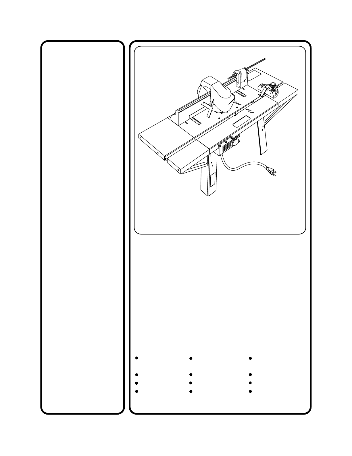
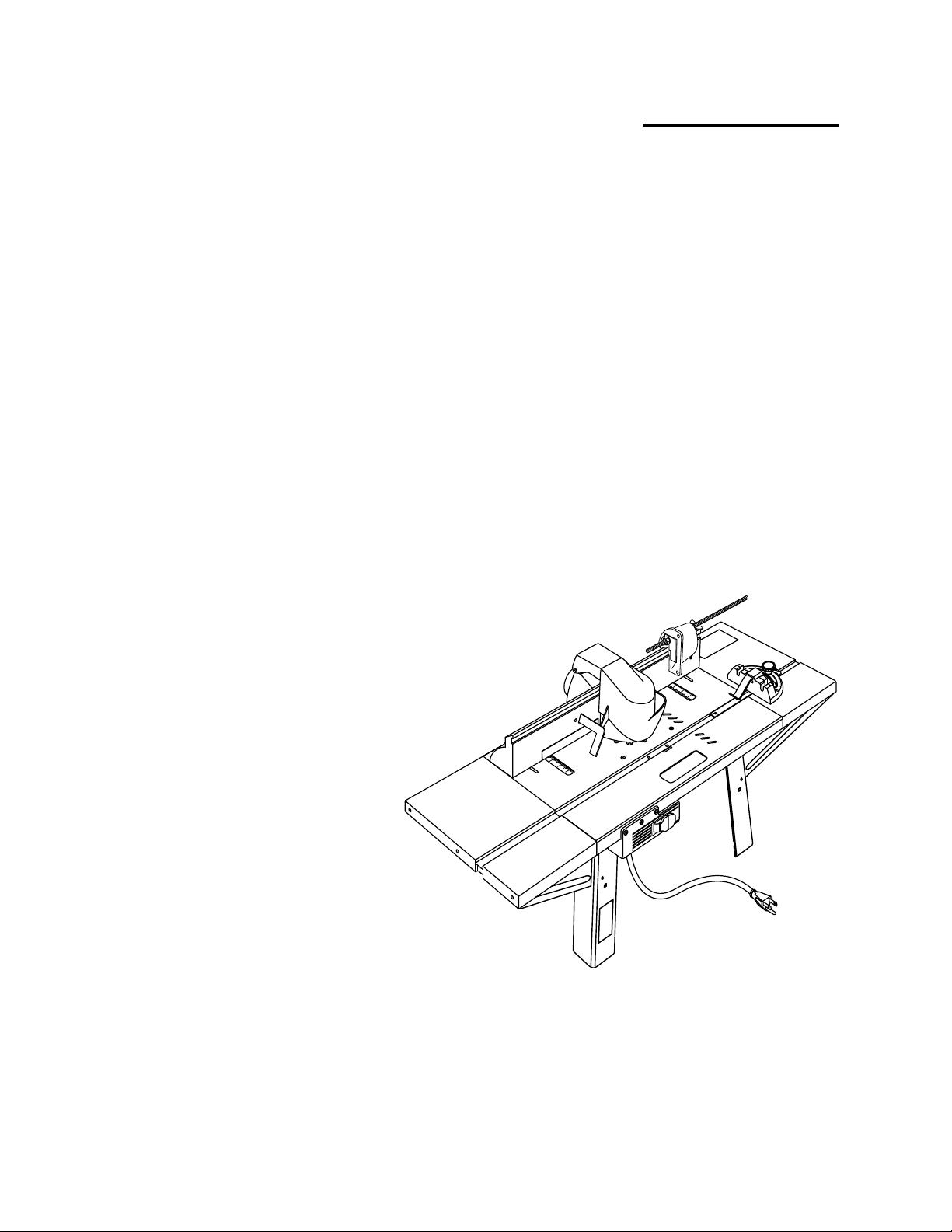
6155 / 6156
Power tools and some accessories NOT included.
Les outils motorisés et certains accessoires NE sont PAS inclus.
NO se incluyen las herramientas eléctricas y ciertos accesorios.
Pages 47-89
Français/Español
CAUTION:
Before using this product,
read this manual entirely
and follow all safety rules
and operating instructions.
MISE EN GARDE:
Avant d'utiliser ce produit,
lire ce manuel entièrement
et respecter toutes les
consignes de sécurité et le
mode d'emploi.
PRECAUCIÓN:
Antes de utilizar este producto,
lea este manual en su totalidad
y siga todas las reglas de
seguridad e instrucciones de
operación.
wolfcraft
ROUTER TABLE
TABLE À TOUPIE
MESA PARA FRESADORA
Safety
instructions
Assembly
Operation
Repair parts
Consignes de
sécurité
Assemblage
Utilisation
Pièces de
rechange
®
Instrucciones
de seguridad
Armado
Operación
Piezas para
reparación

TABLE OF CONTENTS
WARRANTY..................................................................
SAFETY INSTRUCTIONS ............................................
UNPACKING AND CHECKING CONTENTS ...............
INTRODUCTION ..........................................................
FEATURES AND SPECIFICATIONS............................
PACKAGE CONTENTS & HARDWARE LEGEND.......
ASSEMBLY .................................................................
MOUNTING THE ROUTER........................................
WARRANTY
LIMITED LIFETIME WARRANTY
WARRANTY
This wolfcraft® Router Table is warranted
against defects in material and workmanship
for the life of the product. The obligation of the
manufacturer under this warranty is limited to
replacement or repair, at its option, of the
product or of any defective portions thereof.
This warranty extends to the first purchaser
only and does not apply to conditions resulting
from abuse, misuse, alteration, negligence,
improper maintenance, or normal wear and
tear. Unauthorized repairs or tampering with
the product will void this warranty in its
entirety.
If you find a defect in material or
workmanship, contact the wolfcraft®
Customer Service Department by e-mail at
customer.service@woa.wolfcraft.com, by
telephone at 630.773.4777, by fax at
630.773.4805, or through the mail at 333 Swift
Road, Addison, Illinois 60101. You will be
given instructions on how to resolve the
problem or, if the problem cannot be resolved,
on how to return the product to the
manufacturer for repair or replacement.
LIMITATION ON LIABILITY
Manufacturer shall not be liable for loss or
damage of any kind including incidental or
consequential damages, resulting either
directly or indirectly from the use of this
product.
12
21
2
3
4
4
5
6
SECURING THE ROUTER TABLE..........................
SWITCH BOX...........................................................
ASSEMBLING FENCE TO THE ROUTER TABLE....
OPERATION.............................................................
REPAIR PARTS........................................................
FRANÇAIS/ESPAÑOL.............................................
PRODUCT REGISTRATION CARD.........................
26
27
30
32
43
47
91
Some states do not allow the exclusion or
limitation of incidental or consequential
damages so the above limitation or exclusion
may not apply to you. User assumes all risk or
liability in connection with installation or use of
this product.
This warranty gives you specific legal rights and
you may also have other rights which vary from
state to state.
THE EXPRESS WARRANTY HEREIN IS IN
LIEU OF ANY AND ALL OTHER
WARRANTIES, EXPRESSED OR IMPLIED.
NO IMPLIED WARRANTY OF
MERCHANTABILITY IS MADE AND THERE
ARE NO WARRANTIES WHICH EXTEND
BEYOND THE DESCRIPTION ON THE FACE
HEREOF.
WARRANTY CARD
Please complete the information on the
attached warranty card and mail it to
wolfcraft® within 30 days of purchase,
or complete the card on-line at
www.wolfcraft.com. Failure to submit this card
will not adversely affect your warranty rights if
you can otherwise show in a reasonable way
that you were the original purchaser of the
product. Nevertheless, sending this card is a
convenient way to establish in our files the date
of your purchase and help us better meet your
needs in the future.
2
SAFETY INSTRUCTIONS
Safety items throughout this manual are labeled with WARNING and CAUTION.
WARNING
Means that failure to follow this safety statement may result in extensive
product damage, serious personal injury, or death.
CAUTION
WARNING
READ ALL SAFETY INSTRUCTIONS
BEFORE USING
Read the owner's manual carefully. Learn its
applications and limitations as well as the
specific potential hazards.
GROUND ALL TOOLS (UNLESS DOUBLE
INSULATED)
If tool is equipped with an approved 3-conductor
cord and a 3-prong grounding type plug to fit
the proper grounding type receptacle. The
green conductor in the cord is the grounding
wire. NEVER connect the green wire to a live
terminal.
KEEP AWAY FROM HAZARDOUS
MATERIALS
Normal sparking of the motor could ignite
fumes, flammable liquids, or combustibles.
Means that failure to follow this safety statement may result in minor or
moderate personal injury, or property or equipment damage.
NEVER STAND ON TOOL
Serious injury could occur if the tool is tipped
or if the cutting tool is accidentally contacted.
DO NOT store materials above or near the tool
making it necessary to stand on the tool to
reach them.
PROTECT AND USE SUITABLE CORDS
NEVER carry tool by cord or yank it to
disconnect from receptacle. Protect cord from
heat, oil, and sharp edges. For temporary
outdoor operation, use extension cords
intended for outdoor use.
AVOID A DANGEROUS ENVIRONMENT
DO NOT use power tools in damp or wet
locations or expose them to rain. Keep work
area well lit and provide an adequate
surrounding work space.
PROTECT YOURSELF AGAINST PERSONAL
INJURY
DO NOT operate any tool while under the
influence of drugs, alcohol, or any medication.
DRESS FOR SAFETY
Do not wear loose clothing, gloves, neckties, or
jewelry, as these items can get caught and
draw you into moving parts. ALWAYS wear
non-slip footwear. Tie back long hair. Roll long
sleeves above the elbow.
WEAR SAFETY GOGGLES
Wear safety goggles (must comply with ANSI
Z87.1) at ALL times. Also, use face or dust
mask if cutting operation is dusty, and use ear
protectors (plugs or muffs) during extended
periods of operation.
AVOID ACCIDENTAL STARTING
Make sure all switches are in "OFF" position
before plugging in.
CHECK DAMAGED PARTS
Before further use of the tool, a guard or other
part that is damaged should be carefully
checked to ensure that it will operate properly
and perform its intended function. Check for
alignment of moving parts, binding of moving
parts, breakage of parts, mounting, and any
other conditions that may affect its operation.
A guard or other part that is damaged should
be properly repaired or replaced.
CHECK DIRECTION OF FEED
Feed work into a blade or cutter against the
direction of rotation of the blade or cutter only.
NEVER LEAVE TOOL RUNNING
UNATTENDED
Turn power off. Do not leave tool until it
comes to a complete stop.
3
WARNING
CONTINUED
SECURE ROUTER TABLE
DO NOT attempt to use your router table unless
it is fastened firmly to your workbench or rests
stably on the floor.
KEEP HANDS AWAY FROM CUTTING AREA
CAUTION
STORE PROPERLY
Do not store router table outdoors or in a
damp location.
KEEP WORK AREA CLEAN
ALWAYS keep your work area clean,
uncluttered, and well lit. DO NOT work on or
place router table legs on floor surfaces that
are slippery from sawdust, oil, water, or wax.
DO NOT FORCE THE TOOL
Do not force tool or attachment to do a job for
which it was not designed. It will do the job
better and more safely at the rate for which it
was designed.
USE CLAMPS TO HOLD WORK WHEN
PRACTICAL
Using clamps to hold work is safer than using
your hand. It also frees both hands to
operate the tool.
DO NOT OVERREACH
Keep proper footing and balance at all times.
DISCONNECT TOOLS BEFORE SERVICING
When changing bits, make sure router is
unplugged.
KEEP GUARDS IN PLACE
Be sure guards are in working order, properly
adjusted, and aligned.
MAINTAIN TOOLS WITH CARE
Keep tools sharp and clean for best and
safest performance. Follow instructions for
lubricating and changing accessories.
USE RECOMMENDED ACCESSORIES
Consult this manual for recommended
accessories. Follow the instructions that
accompany the accessories. The use of
improper accessories may cause hazards.
REMOVE ADJUSTING KEYS AND
WRENCHES
Form the habit of checking to see that keys
and adjusting wrenches are removed from
the tool before turning it on.
ENSURE SAFETY OF OTHERS
Keep visitors and children a safe distance
away from the work area, especially when
operating a power tool. Visitors should wear
the same safety equipment as the operator.
SAVE THESE INSTRUCTIONS
UNPACKING AND CHECKING CONTENTS
IMPORTANT: Separate all parts from
packaging materials and check each item
against the package contents listed in this
manual, found on page 6.
Your wolfcraft® Router Table is shipped
complete in one carton. Make sure all items
are accounted for before discarding any of the
packaging materials.
INTRODUCTION
The wolfcraft® Router Table is designed to
provide an economical means to extend the
capabilities of your router.
We are certain you will find the wolfcraft®
Router Table a valuable addition to your shop.
NOTE: This manual covers assembly
instructions, setup, operation, and parts lists
for both the Model 6155 Router Table and the
Model 6156 Router Table.
4
FEATURES AND SPECIFICATIONS
6155 & 6156 Table work space.......................................................................................
6155 Table weight...............................................................................................................................
6156 Table weight...............................................................................................................................
6155 Working heights.....................................................................................................................
570 square inches
50 lbs.
30 lbs.
32" to 38"
6156 Working height.................................................................................................................................
6155 Dimensions...........................................................................................
6156 Dimensions................................................................................................
14-1/4"W x 40-1/2"L x 32-38"H
14-1/4"W x 40-1/2"L x 14"H
6155 and 6156 Router Table features include:
• Unitized fence that allows mounting of boards up to 8"
• Front-mounted, keyed power switch with two 120-volt receptacles and circuit breaker protection
• Bottom-accessible outlets accept router and shop vacuum plugs to turn both on at the same time
• Die-cast aluminum top that provides a smooth, clean routing surface
• Reinforced steel extensions for 570 square inches of work surface
• Vertical push shoe that allows vertical cutting of boards up to 4-1/2" wide
• Tabletop measuring guides include scales and large miter guide for
quick and accurate straight or 0 to 60° angle cuts
• Universal router adapting plate, fits most routers
• Fence-mounted feather boards
G
IN
N
R
A
W
4
5
6
0
0
3
5
1
0
15
0
3
5
4
0
6
14"
• Combination dust collector/safety shield
Additional 6155 Router Table features include:
• Exclusive dovetail and box joint jig
• Height-adjustable legs that provide floor mounting from 32" to 38"
• Steel storage tray
5
N
O
L
UL
F
P
F
O
H
US
P
T
E
S
RE
S
T
E
L
T
U
O
NG
RNI
A
W
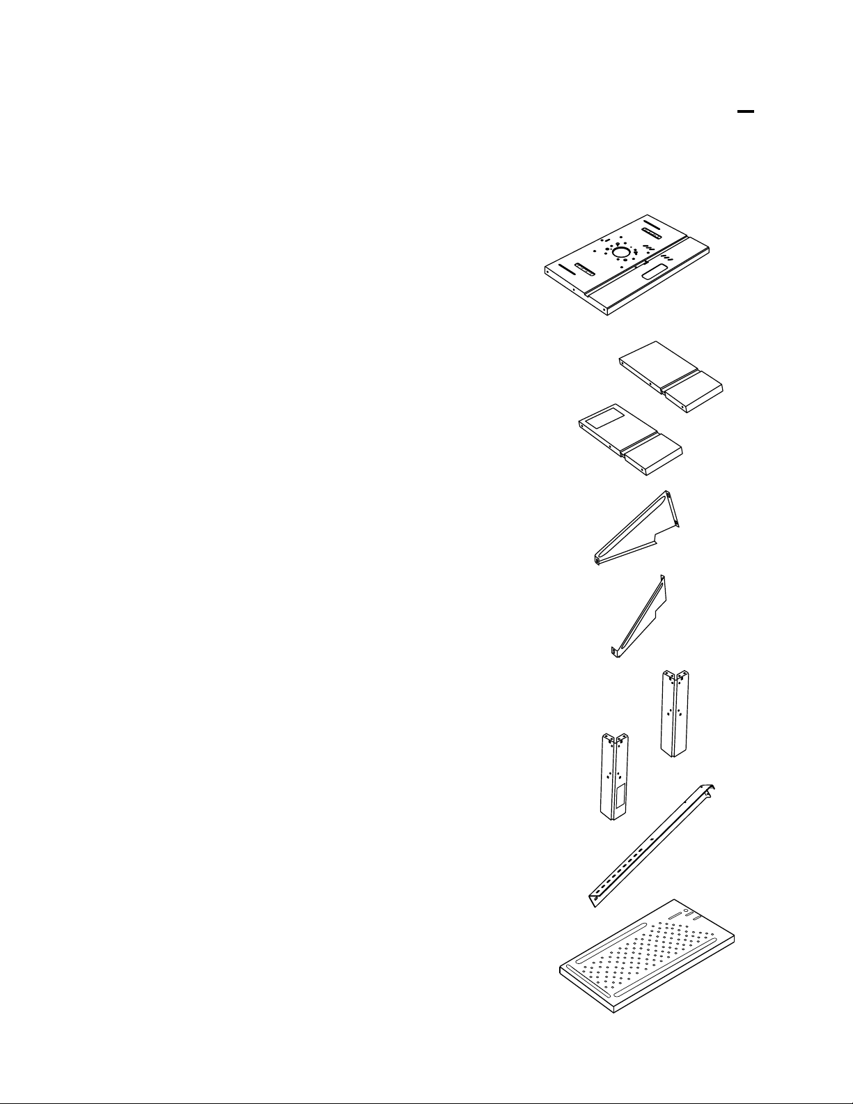
PACKAGE CONTENTS & HARDWARE LEGEND
NOTE: Unless otherwise marked, all parts are common to Models 6155 and 6156.
DESCRIPTION QTY.ITEM
B-1
B-2
C
Tabletop 1A
Extension
6155: 2
6156: 1
Extension, right
1
(Model 6156 only)
Leg support, left 2
Leg support, right 2D
A
B-1
B-2
C
D
RNING
A
W
Leg, shortE-1
Leg, short front left
(Model 6156 only)
Leg, long
(Model 6155 only)
Tool tray
(Model 6155 only)
6155: 4
6156: 3
1E-2
4F
1G
6
E-1
E-2
F
G
G
IN
N
AR
W
PACKAGE CONTENTS & HARDWARE LEGEND (Continued)
NOTE: Unless otherwise marked, all parts are common to Models 6155 and 6156.
ITEM
H
DESCRIPTION
Miter guide head,
aluminum
(Model 6155 only)
Miter guide head, plastic
(Model 6156 only)
Miter bar 1K
Miter pointer 1L
Miter guide knob 1M
QTY.
1
1J
H
J
K
L
M
45
6
0
30
5
1
0
15
0
3
5
4
60
45
6
0
0
3
15
0
5
1
0
3
45
0
6
N
P
Q
R
S
T
Miter guide clamp
(Model 6155 only)
Switch box 1
Retainer 2
Push shoe 1
Clamp rod 1
Clamp plate 1
1
N
P
N
O
L
L
U
F
P
F
O
H
S
U
P
T
E
S
E
R
TS
E
UTL
O
Q
R
S
T
7
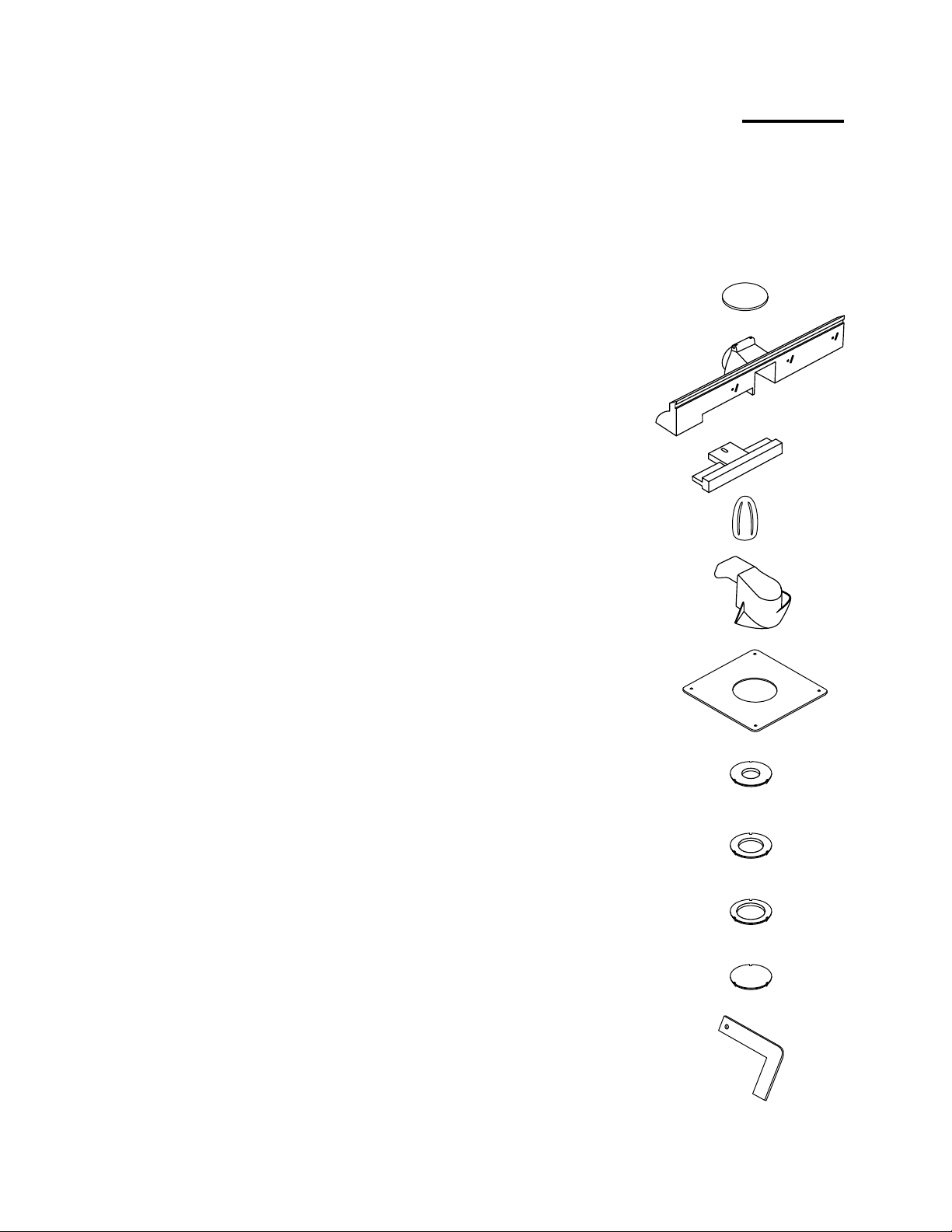
PACKAGE CONTENTS & HARDWARE LEGEND (Continued)
NOTE: Unless otherwise marked, all parts are common to Models 6155 and 6156.
ITEM
U
X
DESCRIPTION
QTY.
Rubber shoe
(Model 6155 only)
Fence 1V
Jointing fence
(attached to fence)
Jointing fence knob 1
Safety shield 1Y
Square adaptor
base plate
4
U
V
1W
W
X
Y
1Z
Z
AA
AB
AC
AD
Tabletop insert,
small hole
Tabletop insert,
medium hole
Tabletop insert,
large hole
Tabletop insert,
solid
Feather flap 3AE
1
1
1
1
AA
AB
AC
AD
AE
8

PACKAGE CONTENTS & HARDWARE LEGEND (Continued)
NOTE: Hardware parts shown (screws, nuts, washers) are actual size.
Unless otherwise marked, all parts are common to Models 6155 and 6156.
ITEM
AF
DESCRIPTION
Pan head screw, zinc
(M5x12)
(Model 6155 only)
Carriage bolt, black
(M6x30)
Washer, black (M6) 2AH
Phillips head screw, selftapping, zinc (M5x12)
Pan head screw,
black (10-32x1/2)
QTY.
1
1AG
21AJ
3AK
AF
AG
AH
AJ
AK
AM
AP
AQ
Hex nut, black
3AL
(10-32)
Square nut, zinc
(M6)
Pan head screw,
18AN
black (M5x16)
Toothed washer,
34
black (M5)
Hex nut, black (M5) 18
AL
2
AM
AN
AP
AQ
9

PACKAGE CONTENTS & HARDWARE LEGEND (Continued)
NOTE: Hardware parts (screws, nuts, washers) shown are actual size.
Unless otherwise marked, all parts are common to Models 6155 and 6156.
ITEM
AR
AS
AT
AU
AV
DESCRIPTION
Carriage bolt, black (M6x16)
QTY.
24
(Model 6155 only)
Toothed washer, black (M6)
24
(Model 6155 only)
Hex nut, black (M6)
24
(Model 6155 only)
Hex nut, black (M8) 1
Washer, black (M8) 2
AR
AS
AT
AU
AV
AW
Wing nut, black (M8)
AX Hex head bolt, zinc
(M6x30)
Cap nut, zinc (M6)
AZ Pivot pin 1
10
1
1
2AY
AW
AX
AY
AZ
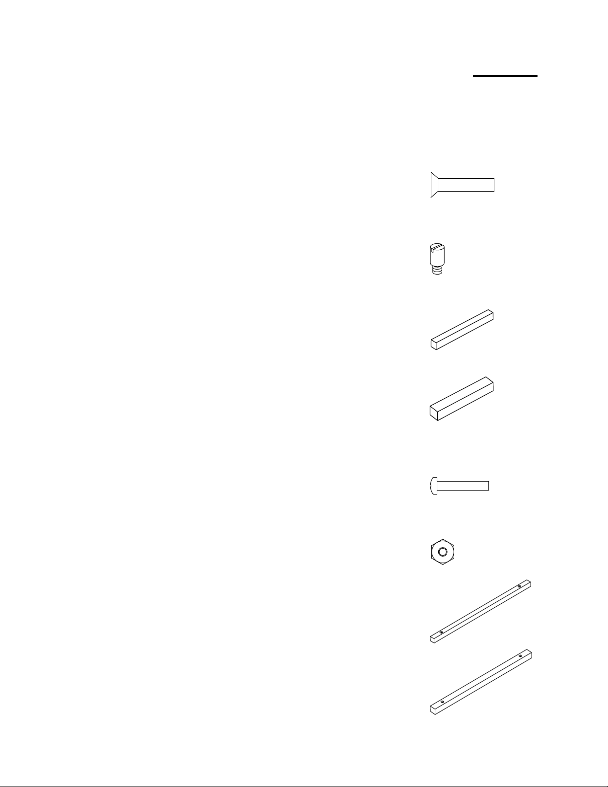
PACKAGE CONTENTS & HARDWARE LEGEND (Continued)
NOTE: Hardware parts (screws, nuts, washers) shown are actual size.
Unless otherwise marked, all parts are common to Models 6155 and 6156.
ITEM
BA
BB
BC
DESCRIPTION
QTY.
Flat head countersink screw,
black (10-32x7/8)
Starter pin, black 1
Spacer bar, 1/4"
(Model 6155 only)
Spacer bar, 3/8"
(Model 6155 only)
4
BA
BB
1
1BD
BC
BD
BE
BF
BG
BH
Pan head screw, zinc (5-40x3/4)
(Model 6155 only)
Hex nut, zinc (5-40)
(Model 6155 only)
Dovetail/box joint bar, 1/4"
(Model 6155 only)
Dovetail/box joint bar, 3/8"
(Model 6155 only)
11
2
2
1
1
BE
BF
BG
BH
ASSEMBLY
NOTE: While most instructions are
common to both units, some instructions
apply to either Model 6155 (floorstanding) OR Model 6156 (benchtop).
Tools Required
#2 and #3 Phillips Screwdrivers
Hammer
Adjustable Wrench
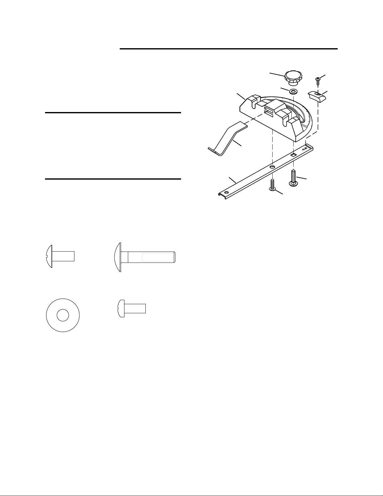
Assemble Metal Miter Guide
(5° Increments, Model 6155 Only)
AF, zinc (1) AG, black (1)
M
H
N
K
AH
45
60
30
5
1
0
15
30
5
4
0
6
AG
AF
Figure 1
3. Attach miter pointer (L) to miter bar
(K) with Phillips head screw (AJ).
AJ
L
AH, black (1) AJ, zinc (1)
1. Assemble miter guide by threading
pan head screw (AF) into miter guide
head (H) through miter bar (K) and by
threading carriage bolt (AG) through
miter bar (K). See Figure 1.
2. Place washer (AH) and knob (M) on
end of carriage bolt (AG). Tighten
knob.
4. Slide clamp (N) into one of two slots
on front of miter gauge.
12
Assemble Plastic Miter Guide
(1° Increments, Model 6156 Only)
AG, zinc (1)
AH, black (1) AJ, zinc (1)
1. Assemble miter guide by threading
carriage bolt (AG) through miter bar
(K). See Figure 2.
2. Place washer (AH) and knob (M) on
end of carriage bolt (AG). Tighten
knob.
3. Attach miter pointer (L) to rear of
miter bar with Phillips head screw
(AJ).
Attach Switch Box to Tabletop
AK, black (3)
M
0
6
AH
45
30
15
0
15
0
3
45
60
J
K
AG
Figure 2
AJ
L
Use a #2 Phillips screwdriver to attach
switch box (P) to front of router table
(A) with 3 pan head screws (AK) and
3 hex nuts (AL). See Figure 3.
P
AL
AK
AL, black (3)
13
Figure 3
Attach Square Nuts and
Retainers
Attach Extensions
AM, zinc (2)
AJ, zinc (4)
1. Place one square nut (AM) in each of
the two slots on the underside of the
aluminum tabletop (A). See Figure 4.
A
Q
AJ
AN, black (6)
AP, black (6)
AQ, black (6)
1. Position extensions (B-1) and (B-2) on
ends of the router tabletop (A) with flat
sides down (upside down). Note
position of miter guide slots in all three
parts. Ensure alignment as shown in
Figure 5.
2. Attach each extension to the ends of
the table using 3 pan head screws
(AN), 3 toothed washers (AP), and 3
hex nuts (AQ).
AM
Figure 4
2. Place one yellow retainer (Q) in each
slot and fasten each with two pan
head screws (AJ). Note orientation
of retainer.
B-2
AP
AQ
MITER GUIDE SLOT
AN
B-1
A
Figure 5
14
Attach Supports to Tabletop
AN, black (4)
AP, black (4)
AQ, black (4)
Attach Height-Adjustable Legs
(Model 6155 Only)
AJ, zinc (16)
AP, black (24)
AN, black (8)
Use 2 pan head screws (AN), 2
toothed washers (AP), and 2 hex nuts
(AQ) to attach a pair of supports (C
and D) to each extension (F). See
Figure 6.
D
C
D
AQ
AP
AN
Figure 6
AQ, black (8)
AR, black (24)
AS, black (24)
C
AT, black (24)
AQ
AP
AJ
AN
F
15
AP
Figure 7
Attach Height-Adjustable Legs
AS
AT
E-1
AR
F
(Model 6155 Only) (continued)
1. Mount four long legs (F) to table using
four pan head screws (AJ) and four
toothed washers (AP) per leg. Use a
#3 Phillips screwdriver to keep from
stripping the screw heads. See
Figure 7.
2. Use 2 pan head screws (AN), 2
toothed washers (AP), and 2 hex nuts
(AQ) to attach a support (C or D) to
each long leg (F).
3. Decide what height you want your
Router Center table to be from the
floor.
4. With the "foot" of short legs (E-1)
pointing upward, align 2 holes in short
leg with 2 holes in long leg at
appropriate height. See Figure 8.
5. Thread 4 carriage bolts (AR) through
the holes in both leg members.
Assemble 1 toothed washer (AS) and
1 hex nut (AT) to each bolt.
Tighten nuts.
6. Attach the three remaining legs in the
same manner. In order to obtain the
same height above the floor, use the
same hole positions as the first leg
you attached.
7. Attach 4 molded "shoes" (U) to feet.
See Figure 9.
8. The table can be leveled by adjusting
short legs (E-1) within the slotted
mounting holes on the long legs (F).
NOTE: Short legs (E-1) mount to the
inside of long legs (F).
Figure 8
U
Figure 9
16
Attach Short Legs
(Model 6156 Only)
AJ, zinc (16)
AP, black (24)
2. Use 2 pan head screws (AN), 2
toothed washers (AP), and 2 hex nuts
(AQ) to attach a support (C or D) to
each leg (E).
Alignment of Tabletop and
Extensions
AN, black (8)
AQ, black (8)
1. Mount four legs (E-1 and E-2) to table
using four pan head screws (AJ) and
four toothed washers (AP) per leg.
Use a #3 Phillips screwdriver to keep
from stripping the screw heads.
NOTE: Leg (E-2) is mounted on the
front left position of the table top with the
safety sticker toward the front of the
table. See Figure 10.
E-1
AQ
E-1
AP
AJ
E-2
Turn tabletop/extension assembly over
and check alignment of extensions and
tabletop by sliding miter guide assembly
through slot. Loosen screws and adjust
alignment of tabletop and extensions if
necessary. Retighten screws.
NOTE: Extension (B-2) to be mounted
on the right side of the table top. See
Figure 11.
B-1
SAFETY
STICKER
G
IN
N
R
A
W
0
N
O
L
L
U
F
P
F
O
H
S
U
P
T
E
S
E
R
S
T
E
L
T
U
O
B-2
4
5
6
0
3
5
1
0
5
1
0
3
5
4
0
6
B-2
AN
E-1
AP
W
A
R
N
I
N
G
Figure 10
B-1
17
SAFETY
STICKER
G
IN
N
AR
W
Figure 11
Attach Tool Tray
(Router Table Model 6155 Only)
AR, black (8)
AS, black (8)
Attach Optional, Second Shelf
(Router Table Model 6155
Only)
1. Size of optional, second shelf (not
provided) will depend on position of
the height-adjustable legs (J). Once
adjusted to operating height,
measure and cut plywood or
medium density fiberboard to fit your
stand.
AT, black (8)
1. Align holes in legs to holes in corners
of tool tray (G). See Figure 12.
2. Use 8 carriage bolts (AR), 8 toothed
washers (AS), and 8 hex nuts (AT) to
attach the tray to the legs. Tighten
securely.
AT
AS
G
2. With the router table in an upright
orientation, place corners of shelf
board on each one of the "brackets"
that protrudes from the heightadjustable legs. See Figure 13,
stand inverted for clarity.
3. Use screws (not provided) to secure
the shelf.
Location of optional shelf
on corners of heightadjustable legs
AR
Figure 13
Figure 12
(Height-adjustable legs
removed for clarity)
18
Assemble Push Shoe
AU (1)
black
AV (2)
black
AW (1)
black
1. On one end of the threaded clamp
rod (S), thread the clamp plate (T)
about 1/2".
Assemble Jointing Fence to
Router Table Fence
AX (1)
zinc
AH (1)
black
1. Using the slots on the fence as
guides, slide the jointing fence (W)
into the router table fence (V).
(Jointing fence may be taped into
place at the factory.)
2. On same end of rod, add washer (AV)
and nut (AU).
3. Slide the clamp rod (S) through push
shoe (R) so the end with the clamp
plate, washer, and nut is on the large
end of the push shoe. See Figure 14.
4. Add washer (AV) and wing nut (AW)
to end of threaded rod.
Vibrations from normal
WARNING
routing may loosen the
washer and bolt that hold the rod to the
plate. Occasionally check these
components to make sure they are tight.
AU
AV
T
AW
AV
S
2. Slide hex head bolt (AX) into bottom
of jointing fence (W) and through hole
in fence (V). Add washer (AH) and
jointing fence knob (X). See Figure
15.
3. Slide the jointing fence into the router
table fence as far as you can.
Remove factory tape if necesssary.
X
AH
W
AX
V
R
Figure 15
Figure 14
19
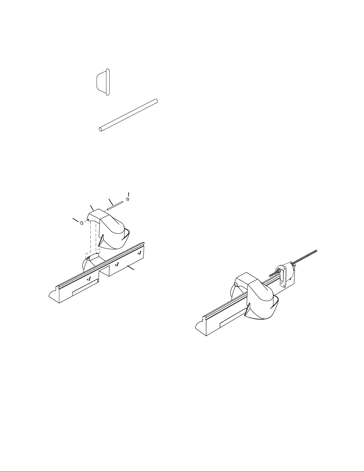
Attach Security Guard Fence
AY, zinc (2)
Assemble Push Shoe to Fence
1. Place push shoe assembly onto
fence so the slot in the push shoe
aligns with rail on fence. See Figure
17.
AZ, black (1)
1. Position the two holes on the security
guard (Y) so that they align with the
two holes on the fence (V). See
Figure 16.
AY
AZ
Y
AY
V
2. With safety shield in the up position,
test moveability of push shoe by
sliding it along fence. It should slide
with ease.
NOTE: It is recommended that you
occasionally lightly lubricate the push
shoe and fence sliding surfaces with
furniture wax.
NOTE: For best performance,
periodically remove any wood chips that
accumulate inside the push shoe slot
and rail.
Figure 16
2. Position one cap nut (AY) on one end
of pivot pin (AZ). Using a hammer,
lightly tap pivot pin until it seats in cap
nut.
3. Slide pivot pin (AZ) through holes in
fence and security guard. Add
second cap nut (AY) and secure on
end of pin.
3. Test moveability by moving security
guard up and down.
Figure 17
20
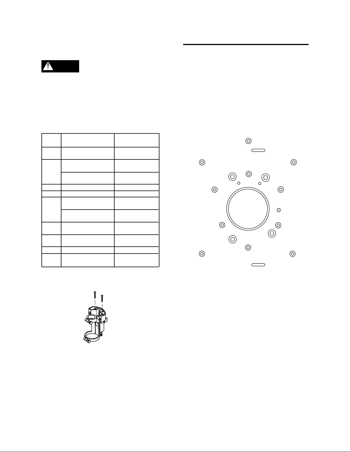
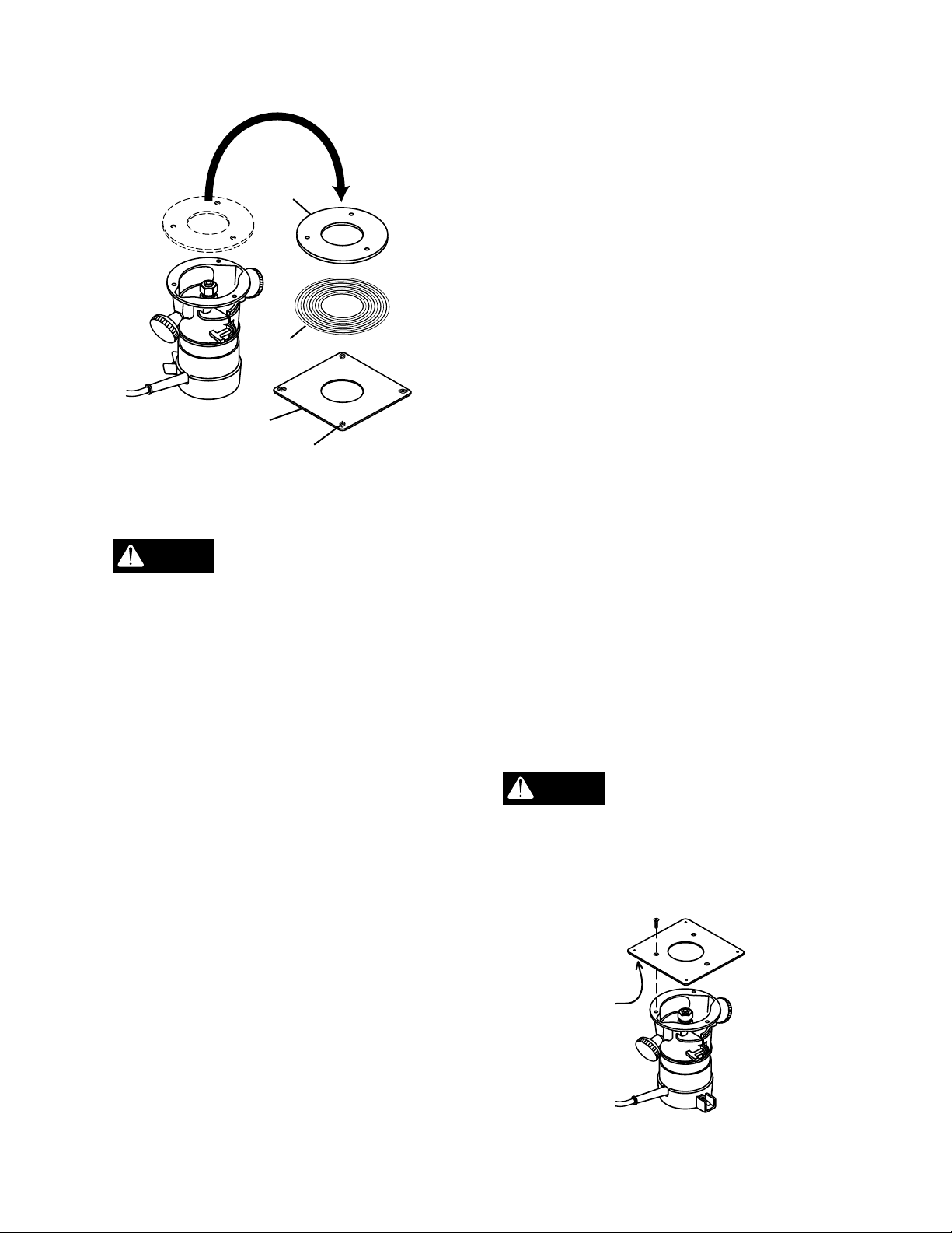
MOUNTING THE ROUTER
Always remove router bits
WARNING
and unplug router before
mounting to router table.
The table will accept routers with bases
up to 7" in diameter. There are two
methods for attaching routers to router
table.
Hole
Pattern
A
B
C
D
E
F*
G
H
J
Dremel™ is a registered trademark of S-B Power Tool
Company.
*Mounts with Dremel™ #330 Router Attachment Kit (not
included, see below).
Router Brand/
Hole Use
Square Adaptor Plate
Mounting Holes
Ryobi
Craftsman
Ryobi
Porter Cable
Skil
Craftsman
Dremel™ Rotary
Hobby Tools
Threaded Hole for
Pilot Pin
Pilot Pin Storage Hole
Dovetail/Box Joint
Fixture Mounting Slots
Specific Model
Numbers
Most routers
mount with plate
#R160K, #R160V,
#R165, #R180
#27500, #27510,
#27511
#R174, #RE175
#690, #6931
#1823, #1835,
#1845-02,
#17504, #17505,
#17506
All
n/a
n/a
n/a
At least three holes should be aligned
for proper support of the router. If fewer
than three holes line up, follow
instructions on how to mount your router
with the square adaptor base plate (Z)
on the next page.
H
J
A
B/C
E
D
B
F
F
D
E
A
B
J
A
E
G
D
B/C
A
Figure 18
If your router is not one of those listed
in the chart, place the router base plate
on top of the router table and rotate the
base plate until the holes are aligned.
When the two hole patterns line up,
your mounting pattern has been
identified. See Figure 18.
21
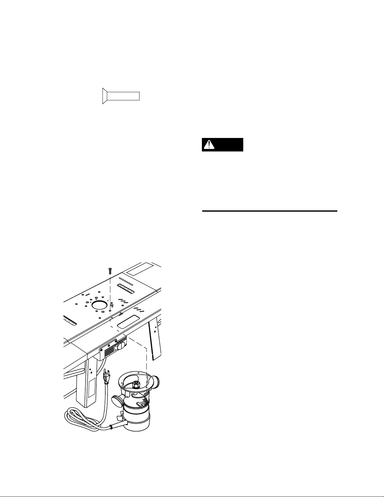
Mount Router Directly to the
P
U
L
L
O
N
P
U
S
H
O
F
F
R
E
S
E
T
O
U
T
L
E
T
S
Table
BA, black (4)
1. Remove router base plate from
router by removing screws.
2. Loosen knobs and slide fence so that
it clears mounting holes.
3. While holding router upside down,
position it underneath the table so
that the center of the router is within
the center ring of the table top.
NOTE: For ease of use, position the
router so the ON-OFF switch is
accessible from the front of the table.
5. Insert router base plate screws
previously removed through holes in
table top and into router mounting
holes. Tighten securely. See Figure
19.
Make sure the screws
WARNING
from your router base
plate match the countersinks in the table
and are long enough to mount the router
to the table. If necessary repace with
screws that are 1/8 to 1/4 inch longer.
4. Rotate router until mounting holes in
router base line up with the holes in
the table top.
G
N
I
N
R
WA
NG
I
RN
A
W
Figure 19
Mounting Routers with Square
Adaptor Plate
Some router models will not mount
directly to this router table. For these
routers, a square adapator base plate is
provided. It will need to be modified to
fit your particular router. Once modified,
and attached to your router, it will mount
directly to the router table.
1. Cut out template on page 23. Also
cut out inner circle of template.
2. Position template on the side of
square adaptor base plate with
welded nuts.
3. Accurately line up the edges of the
template with the edges of the adaptor
base plate. Make sure inner circle
also precisely matches hole in plate.
22
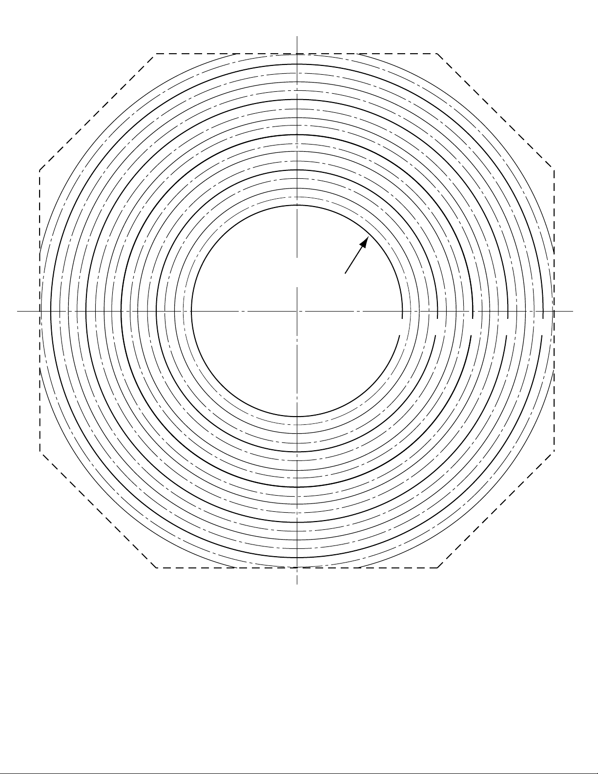
LINE UP WITH HOLE
IN ADAPTER PLATE
ALIGNER AVEC LE TROU DE
LA PLAQUE INTERMEDIAIRE
ALINEE CON EL AGUJERO
EN LA PLACA ADAPTADORA
3" 4" 5" 6" 7"
SQUARE ADAPTER PLATE TEMPLATE
GABARIT DE LA PLAQUE INTERMEDIAIRE
PLANTILLA PARA LA PLACA ADAPTADORA
23
Figure 20
Figura 20

This page intentionally left blank.
Cette page part intentionnellement le vide.
Esta página intensionalmente blanco de
izquierda.
24
ROUTER
BASE PLATE
TEMPLATE
SQUARE
ADAPTOR
BASE
PLATE (Z)
Make sure edges of
CAUTION
template align with edges
WELDNUT
Figure 21
of square adaptor base plate, and inner
circle accurately lines up with hole in
plate. Routing accuracy will suffer if
alignments are not true.
8. Using a pen or pencil, mark the
positions of the mounting holes in the
base plate on the paper template.
9. Take the base plate off the square
adaptor base plate and put it aside.
10. Using a drill bit that matches the
diameter of the holes in the router
base plate, bore into the square
adaptor base plate in the locations
previously marked. (To reduce drill
breakout, use a back-up board.)
11. Remove the paper template from the
square adaptor base plate.
12. Flip the square adaptor base plate
over. With the welded nuts now
facing downward, position the adaptor
plate on the router. (The welded nuts
and the router must be on the same
side of the adapter plate.) See Figure
22.
4. Use tape to attach template to the
square adaptor base plate (Z).
5. Lay the square adaptor base plate on
a flat surface with template and
weldnuts facing up.
6. Unscrew the fasteners that hold the
router base plate to the router and set
them aside.
7. Turn the router base plate over and
position it face down on the template,
which is still taped to the square
adaptor base plate. The position of
the base plate must line up with one
of the circles on the template. See
Figure 21.
13. With the square adaptor base plate
holes and router holes aligned, insert
appropriate screws and tighten.
Make sure the screws
WARNING
from your router base plate
are long enough to mount the square
adaptor base plate securely. If
necessary, replace with screws that are
1/8" to 1/4" longer.
WELDNUT
Figure 22
25
Mount Router (with Square
Adaptor Base Plate) to Table
SECURING THE
ROUTER TABLE
BA, black (4)
Only assemble the router
CAUTION
to the table after you
have attached it to the square adaptor
base plate. Do not attempt to attach
the square adapter plate and then the
router to the table.
1. With router attached, place the
square adaptor base plate
underneath the router table inside the
area provided and against the metal
bosses.
AL
(Model 6156 Only)
DO NOT use the router
WARNING
table unless it is firmly
mounted to a stable work surface.
Failure to securely mount the router
table could lead to serious personal
injury and/or property damage.
Secure router table to the work surface
using wood screws or sheet metal
screws and washers (not provided)
through the holes provided. There are 8
mounting holes. See Figure 24.
Figure 23
2. If your router has a on/off switch,
make sure it faces toward the front of
the table for easy access, if needed.
3. Align the holes in the welded nuts on
the adaptor base plate to the holes in
the bosses.
4. Insert 4 flathead sink screws (BA)
through the holes and tighten them
securely. See Figure 23.
Figure 24
26
SWITCH BOX
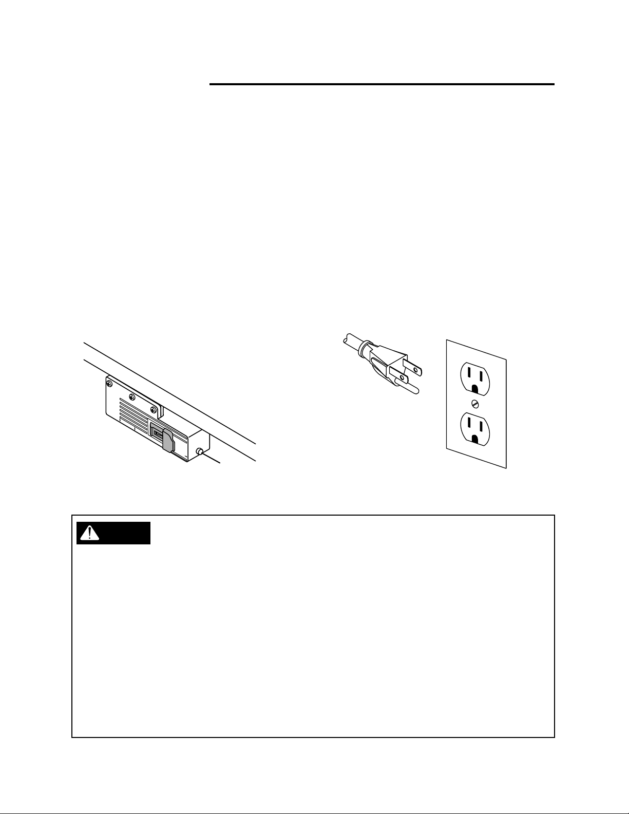
Introduction
A conveniently located Switch Box
allows the operator to:
• turn the router ON and OFF from the
front of the table
• simultaneously operate other devices
such as a light or a vacuum
It also features a resettable, internal
circuit breaker that protects your
equipment against overloads. See
Figure 25.
O
U
T
L
ET
S
P
U
L
L
O
N
P
U
S
H
O
F
R
F
E
S
E
T
Electrical Hookup
Proper grounding diverts potentially
dangerous electricity away from the
operator. The switch box is intended for
use with a three-prong, grounded outlet.
(See Figure 26, below.) The switch
box's electrical cord features an
equipment-grounding connector and a
grounding plug. Insert the plug into an
accommodating outlet that conforms to
the National Electric Code (NEC) and all
local electrical codes.
reset button
Figure 25
WARNING
DO NOT MODIFY THE PLUG
If it does not fit correctly, a qualified electrician
must install a compatible outlet.
AVOID THE RISK OF ELECTRICAL SHOCK
NEVER connect the equipment grounding
connector (green wire) to a "hot" electrical
terminal. When repairing or replacing the
electric plug or cord, DO NOT connect the
grounding connector to a "hot" electrical
terminal.
Consult a qualified electrician if you do not
understand the grounding procedures, or if you
are not sure whether the switch box is correctly
grounded.
Figure 26
REPLACE DAMAGED CORDS
Damaged and/or worn cords must be repaired
or replaced immediately.
Extension cords must be three-wire, 14 gauge
or larger, with three-prong "male" plugs, and
three hole "female" receptacles fabricated to
accept the tool's plug.
The electrical outlets on the bottom of the
switch box accept three-prong grounded plugs
and the two-prong plugs of double insulated
tools.
27
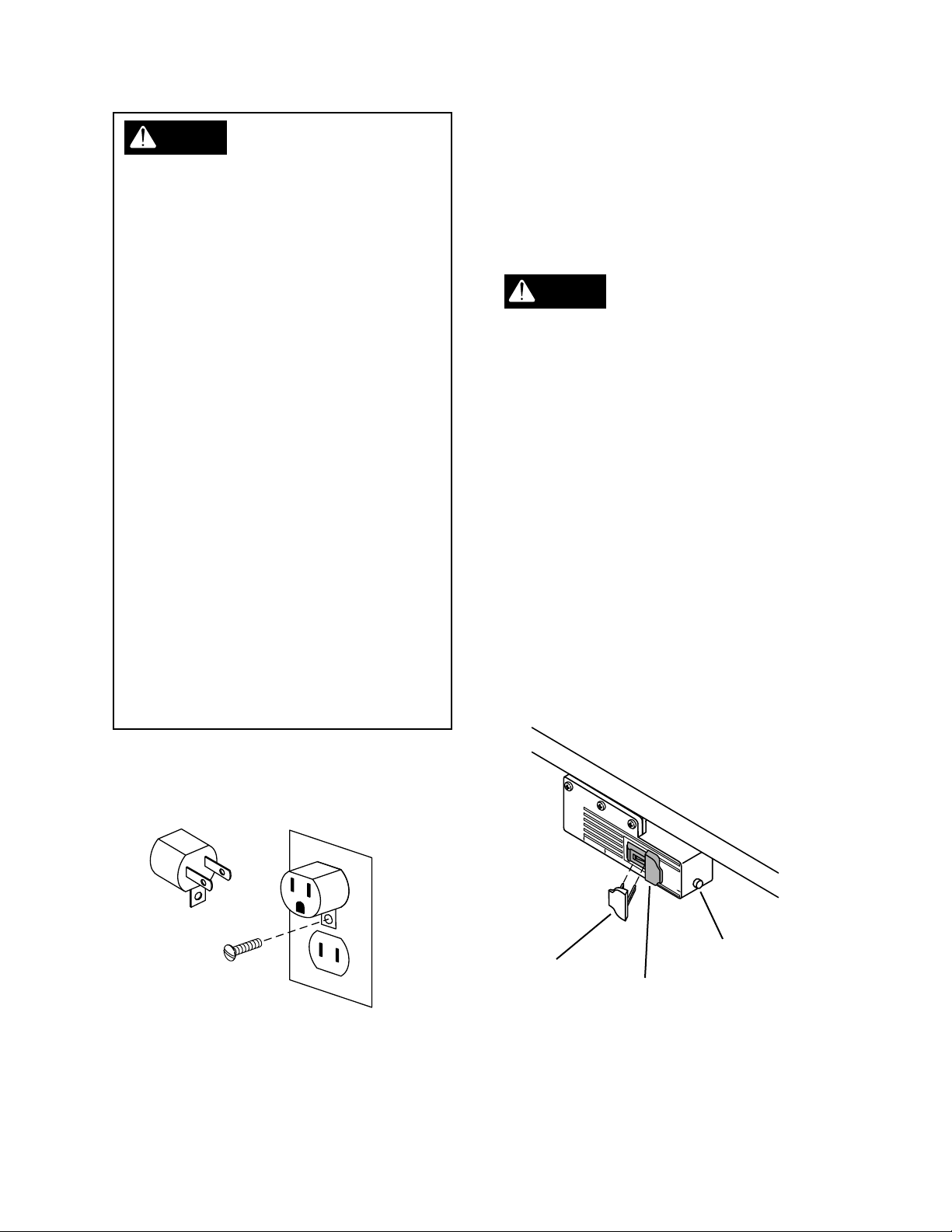
WARNING
Switch Box Familiarization
The electrical outlets on the bottom of the
switch box accept three-prong grounded
plugs and the two-prong plugs of double
insulated tools. If a correctly grounded
outlet is unavailable, use a temporary
adaptor to connect the switch box's threeprong plug to a two-hole receptacle. Make
use of the temporary adaptor only until a
qualified electrician installs a correctly
grounded, three-prong outlet. The green
rigid lug or grounding wire MUST connect to
the ground on the outlet. See Figure 27.
RISK OF ELECTRIC SHOCK
DO NOT touch prongs when inserting or
removing plug from outlet. Improper
grounding can produce potentially
hazardous electrical discharges that can
cause serious injury or death - especially in
wet conditions such as a basement, outside,
or near plumbing.
DO NOT attach a 3-way plug or any other
adaptor to outlets on bottom of switch box.
Only use the switch box when it is properly
assembled to the router table AND when the
router is properly attached to the router
table.
The purpose of this section is to
familiarize the user with the operation of
the switch box BEFORE the router is
plugged in.
DO NOT plug the
WARNING
router in at this time. An
ON switch will start the router and an
unprepared user could possibly be
seriously injured.
The Switch Box also features a safety
key that prevents tools plugged into the
switch box from being turned ON
inadvertently. Removal of the safety
key disables the switch box by locking
the switch in the OFF position. Strike
the switch paddle with your hand to turn
the router OFF in an emergency
situation. Please note paddle switch
positions and reset button at this time.
See Figure 28.
Figure 27
28
OU
T
L
E
T
S
safety key
P
U
L
L
O
N
P
U
S
H
O
F
R
F
E
SET
reset button
paddle switch
Figure 28
 Loading...