


Save this manual for future reference.
Conservez ce guide pour toute référence future.
Guarde este manual para consultarlo en el futuro.
wolfcraft®
OWNER’S
MANUAL
GUIDE DE
L’UTILISATEUR
MANUAL DEL
USUARIO
MODEL NO. 6151 MODELE N° 6151 Modelo 6151
Page 19-40
Français et espagnol
Frances y Español
CAUTION:
Read, understand and follow ALL instructions before using this Router Table.
ATTENTION:
Il est recommandé de lire, de comprendre et de suivre TOUTES les instructions avant d’utiliser cette table de défonceuse.
PRECAUCIÓN:
Antes de usar esta Mesa de Ranuradora lea, comprenda y siga TODAS las instrucciones.
60 |
54 |
30 |
5 1
0 3
45 60
PULL |
ON |
|
|
FF |
|
PU |
SH O |
|
T |
|
|
RESE |
|
|
OUTLE |
TS |
|
(6151)COVER
Power tools and some accessories NOT included.
Les outils motorisés et certains accessoires NE sont PAS inclus. NO se incluyen las herramientas eléctricas y ciertos accesorios.
wolfcraft®
ROUTER TABLE
TABLE DE DEFONCEUSE
MESA DE RANURADORA
OWNER’S MANUAL
GUIDE DE L’UTILISATEUR
MANUAL DEL USUARIO
DO NOT attempt to assemble or operate your Router Table until you have read the safety instructions in this section. Safety items throughout this manual are labeled with WARNING or CAUTION.
Warning means that failure to follow this safety statement may result in extensive
Unpacking and Checking
Contents
Separate all parts from the packing materials and check them against the “Parts List” in this manual. Make sure all parts are accounted for before discarding any of the packing material.
Introduction
Versatile, durable, sensibly priced – wolfcraft® offers the finest quality router tables.
Router table features include:
●a unitized fence that allows mounting of boards up to 8"
●a front-mounted, safety keyed power switch with two 120-volt receptacles
●Laminate top that provides a smooth, clean routing surface
●reinforced steel brackets to assure flatness
●a security guard/dust collector
●a connection for a wet/dry vac for efficient dust collection
●fence-mounted feather boards
The Model 6151 Router Table also has height adjustable legs that provide floor mounting from 32" to 38", a steel storage tray, and a number of other handy, innovative features.
We are sure you will find your wolfcraft router table a valuable addition to your workshop.
NOTE: This manual covers assembly instructions, setup, operation, and parts lists for
Model 6151 Router Table.
Assembling Your Router
Table
Tools Required
#2 and #3 Phillips Screwdriver
Hammer
Adjustable Wrench
Attach Height Adjustable Legs
(See Figure 1.)
1.Place router table top (A) upside-down on a flat surface. Take care not to scratch the table top surface.
2.Attach legs (Q) securely to table top with
16 screws (FF). Use a #3 Phillips screwdriver to keep from stripping the screw heads.
3.Decide what height you want your Router Table to be from the floor.
4.With the “foot” of short leg(P) pointing upward, align 2 holes in short leg with 2 holes in long leg at appropriate height.
NOTE: Short leg (P) mounts inside of long leg (Q).
5.Thread 2 carriage bolts (AA) through the holes in both leg members. Assemble 1 washer (EE) and 1 nut (DD) to each screw. Tighten nuts.
6.Attach the three remaining legs in the same manner. In order to obtain the same height above the floor, use the same hole position as the first leg you attached.
7.Insert and attach 4 molded “shoes”(Z) to feet.
8.Level the table by adjusting the short legs
(P)within the slotted mounting holes on the long legs (Q).
Attach Tool Tray
(See Figure 1.)
1.Align holes in legs to holes in corners of tool tray.
2.Use 8 carriage bolts (AA), 8 washers (EE), and 8 nuts (DD) to attach the tray.
Attach Optional Second Shelf
(See Figure 1.)
1.Place shelf corners on each one of the “brackets” that protrude from the height adjustable legs (shelf board not provided).
2.Use screws (not provided) to attach the shelf.
NOTE: After you have completed the basic assembly, including legs, and shelf, place the router table right-side up on work surface or floor.
3

Figure 1
Assembly for Model 6151 Router Table
|
|
P |
|
|
Optional |
DD |
|
Second Shelf |
Z |
(not provided) |
|
EE |
|
|
DD |
|
|
EE |
|
|
AA 
O Q
AA
AA |
FF |
|
FF
FF
DD
HH
EE
BB |
AA |
(6151)EV-BOTTOM LONG LEG
4

Figure 2
V
LL
N
J II
L
C
L |
CC |
K |
|
T 
Attach Switch Box
(See Figure 2.)
Attach switch box (X) to switch box bracket using 3 screws (GG).
Attach Fence Guides (H)
(See Figure 2.)
Fence guide retains threaded flat stamping
(T) that handles (J) screw into.
LL
F
N |
|
|
II |
|
|
E |
|
|
60 |
45 |
30 |
|
|
15 |
|
|
0 |
|
|
15 |
|
|
30 |
|
|
45 |
B |
|
60 |
|
|
|
|
BB |
U |
S |
|
A
D
X
Y
GG
1.Place a fence guide (H) into each of the two designated slots in the underside of the router table. Make sure to place threaded flat stamping (T) in first.
2.Be sure the extruded side of the fence guide faces toward the table top.
3.Secure each fence guide with 2 screws
(FF).
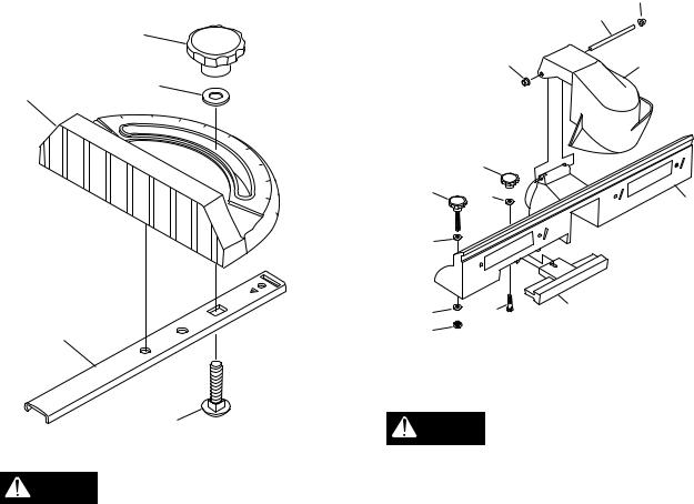
Assemble Plastic Miter Guide
(See Figure 3.)
1.Assemble miter gauge by threading carriage bolt (BB) through miter bar (S).
2.Place washer (II) and knob (N) on end of carriage bolt. Tighten knob.
Figure 3
N
II
E
45  60
60
S
2.Slide pivot pin (V) through holes in fence and security guard. Secure by tapping on two cap nuts (LL).
3.Test moveability by moving security guard up and down.
Figure 4
LL
|
K |
LL |
F |
|
N
J |
II |
B |
|
||
|
|
|
L |
|
|
L |
CC |
C |
|
||
K |
|
WOLF113-34 |
BB
GUIDE1
Vibrations from normal routing WARNING may loosen the washer and bolt
that hold the rod to the plate. Occasionally check these components to make sure they are tight.
Assemble Jointing Fence to Router Table Fence
1.Using the slots on the fence as guides, slide the jointing fence (C) part way into the router table fence (B).
2.Using the adjusting knob (N), washer (II), and bolt (CC), assemble the jointing fence to the router table fence.
3.Slide the jointing fence into the router table fence as far as you can. Tighten the adjusting knob.
Attach Security Guard to Fence
1.Position the two holes on the security guard so that they align with the two holes on the fence. See Figure 4.
Mounting the Router
Always remove router bits and CAUTION unplug router before mounting
to router table.
The table will accept routers with bases up to 7" in diameter. There are two methods for attaching routers to router table:
Mounting Routers With Three Hole Base Plate Hole Configuration Pattern “E.” (See
Figures 5 and 7 with chart.)
1.Remove router base plate from router by removing three screws.
2.Loosen knobs and slide fences so that notches in fences line up to clear mounting holes.
3.While holding router upside down, position it to the underside within the center ring of the table top.
4.Rotate router until the three mounting holes in router base line up with the three larger holes in the table top.
6
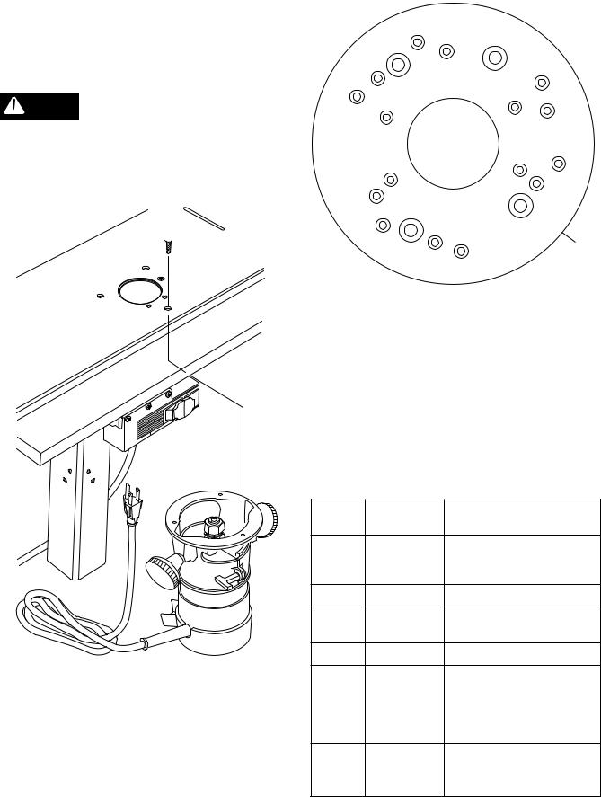
NOTE: For ease of use, position the router so the ON-OFF switch is accessible from the front of the table.
5.Insert three router base plate screws previously removed (T) through holes in table top and into router mounting holes.
Tighten securely.
CAUTION
Make sure the screws from
 router base plate are long enough to mount router securely. Replace if necessary.
Figure 5
 F
F
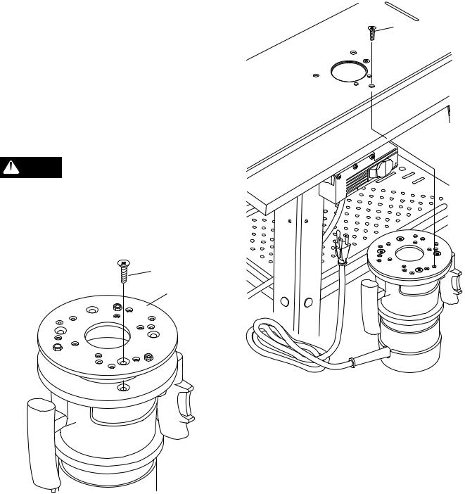
Mounting Routers with 7" Round Adaptor Base Plate
Figure 6
|
E |
A |
|
|
D |
|
|
|
F |
|
H |
|
AB |
|
|
H |
C |
C |
F |
|
|
||
|
|
C |
E |
|
C |
|
|
|
|
|
|
|
D |
|
D |
|
|
|
|
|
A |
|
|
|
F |
AB |
|
|
E |
H |
I |
|
|
||
|
|
|
|
|
|
|
WOLF113-3 |
1.Remove the router base plate.
2.Identify the mounting scheme using the chart and the drawing of the adaptor base plate (I) in Figure 6.
|
TL |
ET |
S |
OU |
|
|
|
|
|
|
ON PULL OFF PUSH 
RESET
NOTE: If your router is not one of those listed in the chart, place the adaptor base plate on top of the router base plate and rotate until the holes in the two plates are aligned. When hole patterns line up, the mounting scheme has been identified.
Hole |
Router |
Model |
Pattern |
Brand |
Numbers |
A |
Ryobi |
#R160K, #R160V, |
|
|
#R165, #R180 |
|
Craftsman |
#27500, #27510, #27511 |
B |
Ryobi |
#R175, #RE175 |
C |
Black and |
#7600, #7604 |
|
Decker |
|
D |
Porter Cable |
#690, #6931 |
WOLF113-8 |
Skil |
#1823, #1835, #1845-02 |
Mount |
||
Directly |
|
|
to Table |
Craftsman |
#17504, #17505, #17506 |
or Use |
|
|
Pattern E |
|
|
F |
Black and |
#7612 |
|
Decker |
|
|
Dewalt |
#DW 610 |
7
NOTE: If your router does not fit adaptor |
(The adaptor base plate comes from the |
base plate or if you wish to mount router |
factory with mounting nuts pressed into it.) |
directly to the table for greater cutting depth, |
See Figure 7. |
remove the router base plate, use it as a |
|
template and drill directly through table top. Figure 8 |
|
Then, countersink the holes and fasten router |
|
to the table top, as described in Attaching |
|
Routers With Three Hole Pattern “E.” |
F |
3. Place the adaptor base plate on the router base as previously determined. See Figure 7.
4. Use the screws removed from the router base plate to attach the adaptor base plate to the router base. Tighten screws securely.
CAUTION
Make sure the screws from
 your router base plate match the countersink in the adaptor base plate and are long enough to mount adaptor base plate securely. Replace if necessary.
Figure 7
HH
I
W

PU |
LL |
ON |
|
OFF |
|||
SH |
|||
PU |
T |
||
SE |
|||
RE |
|
|
TL |
ET |
S |
OU |
|
||
|
|
|
WOLF113-10
5.Mount the router with adaptor base plate using the #10-32 x 1/2" long flat head machine screws (HH) through holes in table top and router base and then into the mounting nuts (W). Tighten securely.
WOLF113-28
Mounting a Dremel® * Rotary Hobby Tool (Not Included)
Extend the capabilities of your Dremel Tool by mounting it to the router table as follows:
(Dremel Tool and Dremel #330 Router Attachment Kit not included):
NOTE: To mount your Dremel Tool, the Dremel #330 Router Attachment Kit must be purchased separately.
*Dremel is a registered trademark of the S-B Power Tool Company.
8
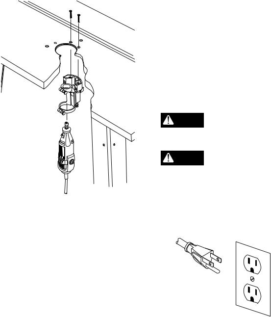
Figure 9
DREMEL ®
NO |
OFF |
WOLF113-24
1.Attach the Dremel® Rotary Hobby Tool to the Tool Holder Assembly from the Dremel #330 Router Attachment Kit as stated in the Router Attachment Kit Owner’s
Manual. See Figure 9.
2.Secure the hobby tool assembly to the router table using the Bracket Mounting Screws from the #330 Router Attachment Kit.
3.The solid insert that comes with this router table can be drilled out off center to give you better small workpiece support.
Switch Box
Introduction
A conveniently located Switch Box allows the operator to:
•turn the router ON and OFF from the front of the table
•simultaneously operate other devices
such as a light or a vacuum
It also features a resettable, internal circuit breaker (NN, Figure 12) that protects your equipment against overloads.
Electrical Hookup
Proper grounding diverts potentially dangerous electricity away from the operator. The switch box is intended for use with a threeprong, grounded outlet. (See Figure 10.) The switch box’s electrical cord features an equip- ment-grounding connector and a grounding plug. Insert the plug into an accommodating outlet that conforms to all local electrical codes and the National Electric Code (NEC).
DO NOT modify the plug. If it WARNING does not fit correctly, a qualified
electrician must install a compatible outlet.
Avoid the risk of electrical
WARNING shock. NEVER connect the equipment grounding connector (green wire) to a “hot” electrical terminal. When repairing or replacing the electric plug or cord, DO NOT connect the grounding connector to a
“hot” electrical terminal.
Figure 10
WOLF108-13
Consult a qualified electrician if you do not understand the grounding procedures, or if you are not sure whether the switch box is correctly grounded.
Damaged and/or worn cords must be repaired or replaced immediately.
Extension cords must be three-wire, 14 gauge or larger, with three-prong “male” plugs, and three hole “female” receptacles fabricated to accept the tool’s plug.
9
The electrical outlets on the bottom of the switch box accept three-prong grounded plugs and the two-prong plugs of double insulated tools.
If a correctly grounded outlet is unavailable, use a temporary adapter to connect the switch box’s three-prong plug to a two-hole receptacle. Make use of the temporary adapter only until a qualified electrician installs a correctly grounded, three-prong outlet. The green rigid lug or grounding wire
MUST connect to the ground on the outlet.
(See Figure 11.)
Figure 11
DO NOT plug the router in at WARNING this time. An ON switch will
start and an unprepared user could possibly be seriously injured.
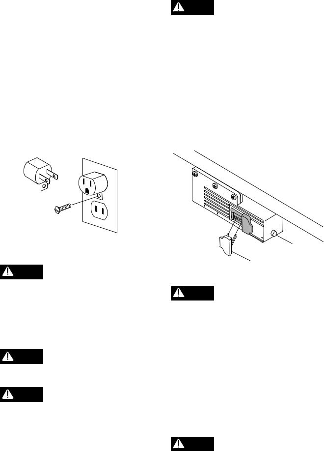
The Switch Box also features a Safety Key (Y) that prevents the router’s ON/OFF switch from being turned ON inadvertently. Removal of the safety key disables the switch box by locking the switch in the OFF position. Strike the switch paddle with your hand to turn the router OFF in an emergency situation. Please note paddle switch positions and reset button
(NN) at this time.
Figure 12
WOLF113-14
RISK OF ELECTRIC SHOCK. WARNING DO NOT touch prongs when
inser ting or removing plug from outlet. Improper grounding can produce potentially hazardous electrical discharges that can, in turn, cause serious injury or death – especially in wet conditions, such as a basement, outside, or near plumbing.
DO NOT attach a 3-way plug or
WARNING any other adapter to outlets on bottom of switch box.
Only use the switch box when it WARNING is properly assembled to the
router table AND when the router is properly attached to the router table.
Switch Box Familiarization (Figure 12)
The purpose of this section is to familiarize the user with the operation of the switch box BEFORE the router is plugged in.
 OUTLETS
PULL |
ON |
|
|
|
|
PUSH OFF |
|
|
RESET |
|
|
|
|
NN |
Y |
|
WOLF113-11 |
Operation of Switch Box and Router
Make sure router switch is OFF
WARNING and switch box is OFF BEFORE proceeding.
1.Insert the safety key.
2.Place router power switch to ON.
NOTE: If your router requires the use of the switch trigger and “LOCK-ON” button, refer to your Router Owner’s Manual for operating instructions.
3.Insert finger under paddle and pull switch to ON position.
4.To turn router OFF push paddle down.
Router bit must come to a com- WARNING plete stop before leaving router
table unattended.
10
5.Lock switch to OFF position by removing key from switch box.
For Routers With “LOCK-ON” Feature
The “LOCK-ON” feature that will not permit the router to be turned ON by the switch box, but it can be turned OFF by the switch box. Operate as follows:
1.Place the switch box to ON as previously described. The router should NOT start even though the trigger lock is in the
“LOCK-ON” position. Refer to your Router
Owner’s Manual.
2.To star t router, depress trigger and engage “LOCK-ON” button. Router should start right up.
NOTE: The router will not start if the router switch is already in the “LOCK-ON” position.
In this case, unlock the trigger, depress the trigger to start the router, then re-engage the “LOCK-ON” button.
3.To turn router OFF push switch paddle down.
Circuit Breaker (See Figure 12.)
If an overload occurs, the circuit breaker inside the Switch Box trips and interrupts power to the router and any accessories. If this happens:
1.Unplug the power cord.
2.Remove the workpiece from the router bit and table.
3.Find the cause of the overload and correct.
4.Push the reset button (NN) to reset it. See Figure 12.
5.Follow instructions under Operation of Switch Box and Router to reset router.
When router table is not in use
WARNING always:
1.Place the switch box in OFF position and remove the safety key.
2.Place router power switch to OFF position.
3.Unplug switch box from wall outlet.
4.Remove router bit.
5.Make sure router collet assembly is below router table.
6.Remove and place safety key in a secure location. Remember where you place the safety key.
If a fuse blows, or a circuit WARNING breaker trips, or the router
stalls, or if the power fails for any other reason, place the switch box in the OFF position, remove the safety key, and unplug the switch box from the wall outlet.
Table Flatness Adjustment
Your router table comes equipped with two “L” brackets mounted under it to help ensure the flatness of the working surface. If the router table should ever become warped, the flatness can be adjusted by shimming under the
“L” bracket. Loosen “L” bracket mounting screws and place shims or washers as necessary. Tighten “L” bracket screws securely. Check table top flatness with a straightedge or the edge of a carpenter’s square. See Figure 13.
Figure 13
WOLF113-27
Operation
Connecting a Vacuum
A hole is provided in the fence which will accept standard 2-1/4" vacuum hose connections. If the vacuum is plugged into the switch box, it will turn ON and OFF simultaneously with the router.
11

Assemble Fence to the Router Table
(See Figure 14.)
Figure 14
-
.
-
12
G421
 Loading...