


WTW5790ST2
Whirlpool WTW5790ST2, WTW5790SQ2, WTW5790SQ0, WTW5590ST2, WTW5590SQ2 Installation Guide
...
WASHERINSTAILATIONINSTRUCTIONS
INSTRUCTIONSD'INSTAILATIONDELALAVEUSE
Tableof Contents/Tabledes matibres
WASHER SAFETY .................................................................................. 1
INSTALLATION REQUIREMENTS ........................................................ 2
Tools and Parts ................................................................................... 2
Location Requirements ....................................................................... 3
Drain System ....................................................................................... 3
Electrical Requirements ...................................................................... 4
INSTALLATION INSTRUCTIONS .......................................................... 4
Before You Star_ .................................................................................. 4
Remove Shipping Materials ................................................................ 4
Connect Drain Hose ............................................................................ 6
Connect the Inlet Hoses ...................................................................... 6
Secure the Drain Hose ........................................................................ 7
Level the Washer ................................................................................. 7
Complete Installation ........................................................................... 8
Para obtener acceso al manual de uso y cuidado en espa_ol, o para obtener informaci6n adicional acerca de su producto, visite:
www.whirlpool.com.
Tenga listo su nOmero de modelo completo. Podra encontrar el nOmero de modelo y de serie en la etiqueta ubicada debajo de la tapa
de la lavadora.
SECURITF: DE LA LAVEUSE ...................................................................... 9
EXIGENCES D'INSTALLATION ................................................................. 9
Outillage et pieces .................................................................................... 9
Exigences d'emplacement .................................................................... 10
Systeme de vidange .............................................................................. 10
Specifications _lectriques ...................................................................... 11
INSTRUCTIONS D'INSTALLATION ......................................................... 12
Avant de commencer ............................................................................. 12
Retrait du materiel d'exp_dition ............................................................. 12
Raccordement du tuyau de vidange ..................................................... 13
Raccordement des tuyaux d'arriv_e d'eau ........................................... 13
Immobilisation du tuyau de vidange ...................................................... 14
R_glage de I'aplomb de la laveuse ........................................................ 15
Achever I'installation .............................................................................. 16
WASHERSAFETY
Your safety and the safety of others are very important.
We have provided many important safety messages in this manual and on your appliance. Always read and obey all safety
messages.
This is the safety alert symbol.
This symbol alerts you to potential hazards that can kill or hurt you and others.
All safety messages will follow the safety alert symbol and either the word "DANGER" or "WARNING."
These words mean:
You can be killed or seriously injured if you don't immediately
follow instructions.
You can be killed or seriously injured if you don't follow
instructions.
All safety messages will tell you what the potential hazard is, tell you how to reduce the chance of injury, and tell you what can
happen if the instructions are not followed.
W10150593A
INSTALLATIONREQUIREMENTS
Gather the required tools and parts before starting installation.
The parts supplied are in the washer basket.
Tools needed for connecting the drain hose and water
inlet hoses:
• Pliersthat open to 1%6" • Flashlight (optional)
(3.95 cm)
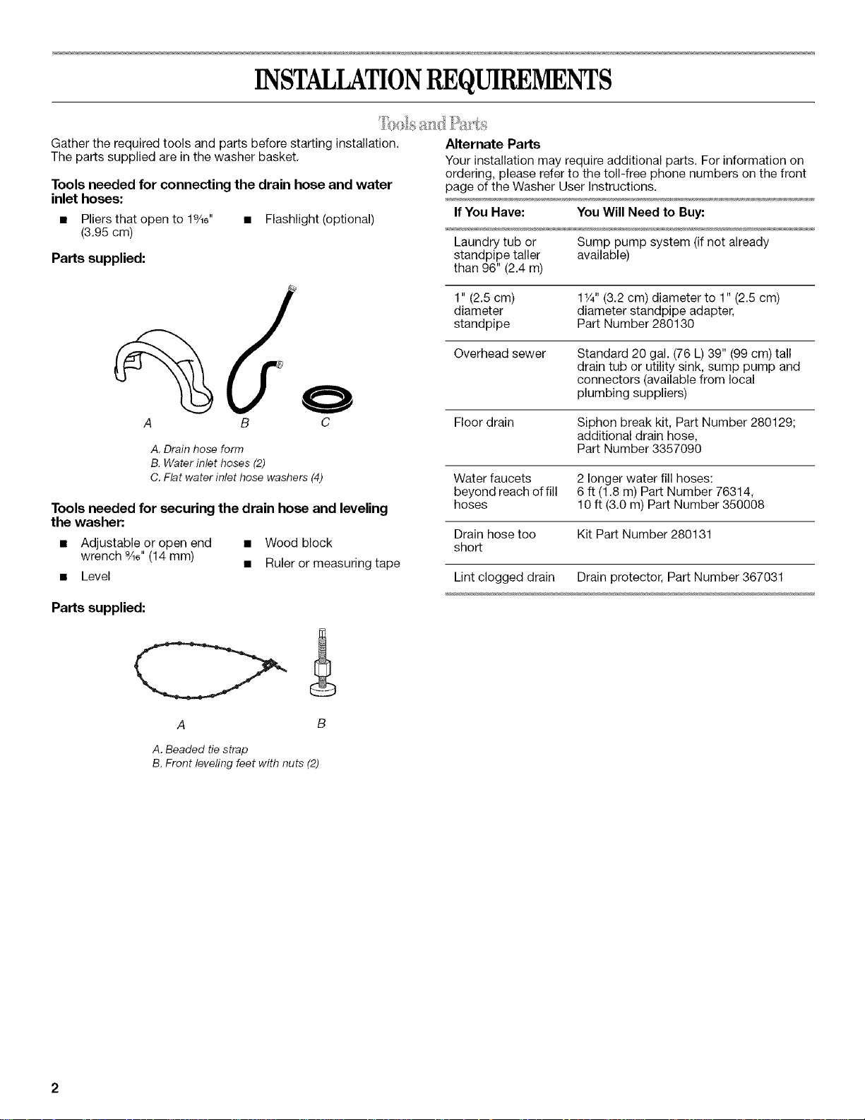
Parts supplied:
A B C
A. Drain hose form
B. Water inlet hoses (2)
C. Flat water inlet hose washers (4)
Tools needed for securing the drain hose and leveling
the washer:.
• Adjustable or open end • Wood block
wrench %6" (14 mm) • Ruler or measuring tape
• Level
Alternate Parts
Your installation may require additional parts. For information on
ordering, please refer to the toll-free phone numbers on the front
page of the Washer User Instructions.
If You Have: You Will Need to Buy:
Laundry tub or Sump pump system (if not already
standpipe taller available)
than 96" (2.4 m)
1" (2.5 cm) 11/4"(3.2 cm) diameter to 1" (2.5 cm)
diameter diameter standpipe adapter,
standpipe Part Number 280130
Overhead sewer Standard 20 gal. (76 L) 39" (99 cm) tall
drain tub or utility sink, sump pump and
connectors (available from local
plumbing suppliers)
Floor drain Siphon break kit, Part Number 280129;
additional drain hose,
Part Number 3357090
Water faucets 2 longer water fill hoses:
beyond reach of fill 6 ft (1.8 m) Part Number 76314,
hoses 10 ft (3.0 m) Part Number 350008
Drain hose too Kit Part Number 280131
short
Lint clogged drain Drain protector, Part Number 367031
Parts supplied:
A B
A. Beaded tie strap
B. Front leveling feet with nuts (2)
Selecting the proper location for your washer improves
performance and minimizes noise and possible washer "walk."
Your washer can be installed in a basement, laundry room, closet,
or recessed area. See "Drain System."
IMPORTANT: Do not install or store the washer where it will be
exposed to the weather.
Proper installation is your responsibility.
You will need:
• A water heater set to deliver 120°F (49°C) water to the washer.
• A grounded electrical outlet located within 4 ft (1.2 m) of
where the power cord is attached to the back of the washer.
See "Electrical Requirements."
• Hot and cold water faucets located within 3 ft (90 cm) of the
hot and cold water fill valves, and water pressure of 5-100 psi
(34.5-690 kPa), Washers with triple dispensers require
20-100 psi (138-690 kPa) for best performance.
• A level floor with a maximum slope of 1" (2.5 cm) under entire
washer. Installing the washer on carpeting is not
recommended.
• A sturdy floor to support the washer weight (washer, water
and load) of 315 Ibs (143 kgs).
Do not store or operate your washer in temperatures at or below
32°F (O°C). Some water can remain in the washer and can cause
damage in low temperatures. See "Washer Care" in the Washer
User Instructions for information on winterizing.
Recessed area or closet installation
The washer can be installed using the standpipe drain system
(floor or wall), the laundry tub drain system, or the floor drain
system. Select the drain hose installation method you need. See
"Tools and Parts."
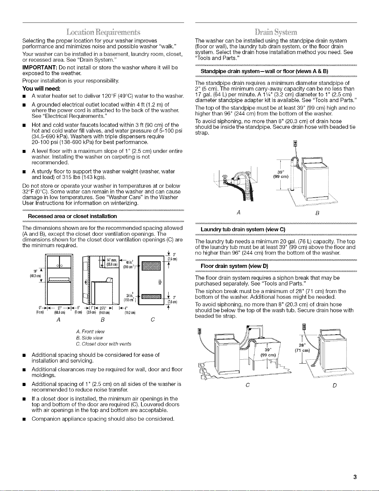
Standpipe drain system--wall or floor (views A & B)
The standpipe drain requires a minimum diameter standpipe of
2" (5 cm). The minimum carry-away capacity can be no less than
17 gal. (64 L) per minute, A 1V4"(3.2 cm) diameter to 1" (2,5 cm)
diameter standpipe adapter kit is available, See "Tools and Parts,"
The top of the standpipe must be at least 39" (99 cm) high and no
higher than 96" (244 cm) from the bottom of the washer.
Toavoid siphoning, no more than 8" (20.3 cm) of drain hose
should be inside the standpipe, Secure drain hose with beaded tie
strap.
A
The dimensions shown are for the recommended spacing allowed
(A and B), except the closet door ventilation openings. The
dimensions shown for the closet door ventilation openings (C) are
the minimum required.
__ 0_'
(7.6crn)
__ 3_
17.6crn}
19,5E
(48.3crn)
JL
0"_ 27"---_N0" -_11"1_-25½" _'1
(0cm) (60,6crn)(0crn)(2.Scrn)(04.8crn)
A
A. Front view
B. Side view
C. Closet door with vents
B C
(310crn2}1" _
24in._.__
(100crn2)1
I-<-4"
(10.2cm)
m
• Additional spacing should be considered for ease of
installation and servicing.
• Additional clearances may be required for wall, door and floor
moldings.
• Additional spacing of 1" (2.5 cm) on all sides of the washer is
recommended to reduce noise transfer.
If a closet door is installed, the minimum air openings in the
top and bottom of the door are required (C). Louvered doors
with air openings in the top and bottom are acceptable.
Companion appliance spacing should also be considered.
Laundry tub drain system (view C)
The laundry tub needs a minimum 20 gal. (76 L) capacity. The top
of the laundry tub must be at least 39" (99 cm) above the floor and
no higher than 96" (244 cm) from the bottom of the washer.
Floor drain system (view D)
The floor drain system requires a siphon break that may be
purchased separately. See "Tools and Parts."
The siphon break must be a minimum of 28" (71 cm) from the
bottom of the washer. Additional hoses might be needed.
Toavoid siphoning, no more than 8" (20.3 cm) of drain hose
should be below the top of the wash tub. Secure drain hose with
beaded tie strap.
Electrical Shock Hazard
Plug into a grounded 3 prong outlet.
Do not remove ground prong.
Do not use an adapter.
Do not use an extension cord.
Failure to follow these instructions can result in death,
fire, or electrical shock.
• A 120 volt, 60 Hz., AC only, 15- or 20-amp, fused electrical
supply is required. A time-delay fuse or circuit breaker is
recommended. It is recommended that a separate circuit
serving only this appliance be provided.
• This washer is equipped with a power supply cord having a
3 prong grounding plug.
• To minimize possible shock hazard, the cord must be plugged
into a mating, 3 prong, grounding-type outlet, grounded in
accordance with local codes and ordinances. If a mating
outlet is not available, it is the personal responsibility and
obligation of the customer to have the properly grounded
outlet installed by a qualified electrician.
• If codes permit and a separate ground wire is used, it is
recommended that a qualified electrician determine that the
ground path is adequate.
• Do not ground to a gas pipe.
• Check with a qualified electrician if you are not sure the
washer is properly grounded.
• Do not have a fuse in the neutral or ground circuit.
GROUNDING INSTRUCTIONS
For a grounded, cord-connected washer:
This washer must be grounded. In the event of a malfunction
or breakdown, grounding will reduce the risk of electrical
shock by providing a path of least resistance for electric
current. This washer is equipped with a cord having an
equipment-grounding conductor and a grounding plug. The
plug must be plugged into an appropriate outlet that is
properly installed and grounded in accordance with all local
codes and ordinances.
WARNING: Improper connection of the equipment-
grounding conductor can result in a risk of electric shock.
Check with a qualified electrician or serviceman if you are in
doubt as to whether the appliance is properly grounded.
Do not modify the plug provided with the appliance - if it will
not fit the outlet, have a proper outlet installed by a qualified
electrician.
For a permanently connected washer:
This washer must be connected to a grounded metal,
permanent wiring system, or an equipment grounding
conductor must be run with the circuit conductors and
connected to the equipment-grounding terminal or lead on
the appliance.
INSTALLATIONINSTRUCTIONS
Excessive Weight Hazard
Use two or more people to move and install washer.
Failure to do so can result in back or other injury.
NOTE: To avoid floor damage, set the washer onto cardboard
before moving across floor.
Removing the shipping material is necessary for proper operation.
If the shipping material is not removed, the washer will make
excessive noise.
1. Move the washer to within approximately 3 ft (90 cm) of its
final location.
2. The washer must be in the upright position and not tilted
before removing the shipping material.
3. Locate the yellow shipping materials on the rear of the
machine, near the bottom. Follow the steps for your particular
model, either the one with the straight power cord and cord
restraint or the looped power cord version.
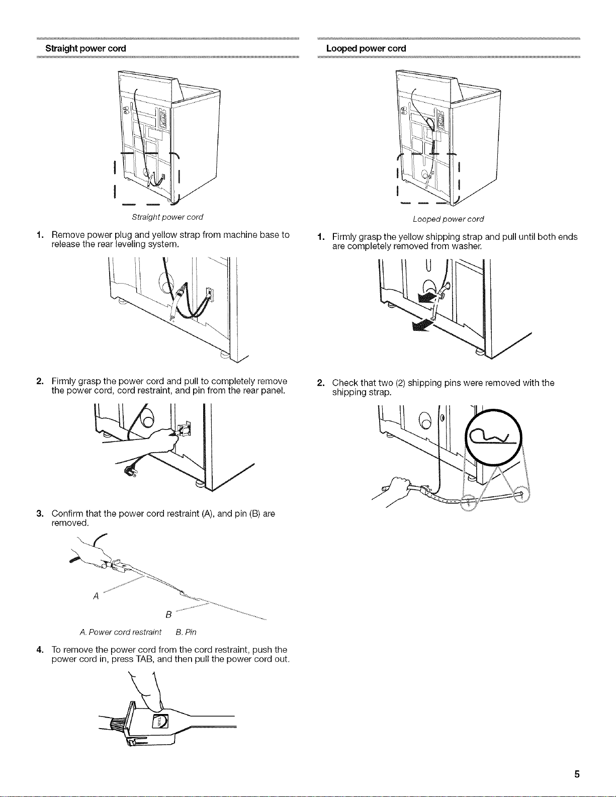
Straight power cord Looped power cord
I
I
Straight power cord
Remove power plug and yellow strap from machine base to
release the rear leveling system.
J
2=
Firmly grasp the power cord and pull to completely remove
the power cord, cord restraint, and pin from the rear panel.
Looped power cord
Firmly grasp the yellow shipping strap and pull until both ends
are completely removed from washer.
2. Check that two (2) shipping pins were removed with the
shipping strap.
3. Confirm that the power cord restraint (A), and pin (B) are
removed.
A
B
A. Power cord restraint B. Pin
4=
To remove the power cord from the cord restraint, push the
power cord in, press TAB, and then pull the power cord out.
 Loading...