


WOS72EC7HV00
Whirlpool WOS72EC7HV00, WOS72EC7HS01, WOS72EC7HS00, WOS72EC0HV01, WOS72EC0HV00 Installation Guide
...
INSTALLATION INSTRUCTIONS 27" (68.6 CM)
AND 30" (76.2 CM) ELECTRIC SINGLE
AND DOUBLE BUILT-IN OVEN
INSTRUCTIONS D’INSTALLATION FOUR
ÉLECTRIQUE ENCASTRÉ 27" (68,6 CM)
ET 30" (76,2 CM) - SIMPLE ET DOUBLE
INSTRUCCIONES DE INSTALACIÓN DEL
HORNO EMPOTRADO ELÉCTRICO SIMPLE
Y DOBLE DE 27" (68,6 CM) Y 30" (76,2 CM)
Table of Contents/Table des matières/Índice
BUILT-IN OVEN SAFETY ......................... 2
INSTALLATION REQUIREMENTS .......... 2
Tools and Parts ...................................... 2
Location Requirements ......................... 3
Electrical Requirements ........................ 6
INSTALLATION INSTRUCTIONS ............ 7
Prepare Built-In Oven ............................ 7
Remove Oven Door(s) ........................... 7
Replace Oven Door(s) ........................... 8
Positioning Oven Feet for Multiple
Cabinet Cutout Heights ........................ 8
Make Electrical Connection ................ 13
Install Oven .......................................... 14
Install Warming Drawer Deflector Kit .. 16
Complete Installation .......................... 16
SÉCURITÉ DU FOUR ENCASTRÉ ....... 17
EXIGENCES D’INSTALLATION ............17
Outillage et pièces ............................... 17
Exigences d’emplacement .................. 18
Spécifications électriques ................... 21
INSTRUCTIONS D’INSTALLATION ...... 22
Préparation du four encastré .............. 22
Dépose de la/des porte(s) du four ...... 22
Réinstallation la porte(s) du four ......... 23
Positionnement des pieds du four
pour des ouvertures d’encastrement
de hauteur différente ........................... 24
Raccordement électrique ....................28
Installation du four ............................... 30
Installation de l’ensemble de
déflecteur du tiroir-réchaud ................31
Achever l’installation ........................... 32
SEGURIDAD DEL
HORNO INTEGRADO ............................ 33
REQUISITOS DE INSTALACIÓN .......... 33
Herramientas y piezas ......................... 33
Requisitos de ubicación ...................... 34
Requisitos eléctricos ........................... 37
INSTRUCCIONES DE INSTALACIÓN .. 38
Prepare el horno integrado ................. 38
Retire la puerta del horno .................... 38
Vuelva a colocar la puerta del horno ..39
Ubicación de las patas del
horno para múltiples alturas
de corte del armario ............................ 39
Haga la conexión del
suministro eléctrico ............................. 44
Instale el horno .................................... 45
Instale el kit de deflector
para cajón de calentamiento .............. 47
Finalización de la instalación .............. 47
IMPORTANT:
Save for local electrical inspector’s use.
IMPORTANT :
À conserver pour consultation par l’inspecteur local des installations électriques.
IMPORTANTE:
Guarde para tener a disposición del inspector de electricidad local.
W11040298A
BUILT-IN OVEN SAFETY
INSTALLATION REQUIREMENTS
Gather the required tools and parts before starting
installation. Read and follow the instructions provided
with any tools listed here.
Tools Needed
■ Phillips screwdriver
■ Measuring tape
■ Hand or electric drill (for wall cabinet installations)
■ 1" (2.5 cm) drill bit (for wall cabinet installations)
■ Level
■ Flat-blade screwdriver
Parts Needed
■ UL Listed or CSA Approved conduit connector
■ UL Listed wire connectors
■ Warming Drawer Deflector Kit (for ovens installed
above a warming drawer)
Order Part Number W10510613 for white 27" (68.6 cm) kit
Order Part Number W10531009 for black 27" (68.6 cm) kit
Order Part Number W10536338 for stainless steel 27"
(68.6 cm) kit
Order Part Number W10888988 for black stainless steel
27" (68.6 cm) kit
Order Part Number W10510614 for white 30" (76.2 cm) kit
Order Part Number W10531010 for black 30" (76.2 cm) kit
Order Part Number W10536339 for stainless steel 30"
(76.2 cm) kit
Order Part Number W10727416 for black stainless steel 30"
(76.2 cm) kit
To order, see the “Assistance or Service” section
of the Use and Care Guide.
Tools and Parts
Parts Supplied
■ #8-14 x 3/4" (19 mm) screws: single ovens (2),
double ovens (4)
■ #8-18 x 3/8" (9.5 mm) screws: bottom vent (2)
■ #8-18 x 1/4" 6.4 mm) screws: bottom vent trim (4)
■ #8-18 x 3/8" (09.5 mm) screws: double oven feet (4)
■ Bottom vent
■ Bottom vent trim
■ Rear feet - double oven (2)
■ Front feet - double oven (2)
Check local codes. Check existing electrical supply. See the
“Electrical Requirements” section.
It is recommended that all electrical connections
be made by a licensed, qualified electrical installer.
2
Location Requirements
G
IMPORTANT: Observe all governing codes and ordinances.
■ Cabinet opening dimensions that are shown must be used.
Given dimensions provide minimum clearance with oven.
■ Recessed installation area must provide complete
enclosure around the recessed portion of the oven.
■ Grounded electrical supply is required. See the
“Electrical Requirements” section.
■ Electrical supply junction box should be located 3" (7.6 cm)
maximum below the support surface when the oven is
installed in a wall cabinet. A 1" (2.5 cm) minimum diameter
hole should have been drilled in the right rear or left rear
corner of the support surface to pass the appliance cable
through to the junction box.
NOTE: For undercounter installation, it is recommended
that the junction box be located in the adjacent right or
left cabinet. If you are installing the junction box on rear
wall behind oven, it is recommended that the junction box
be recessed and located in the upper center of the cabinet.
■ Oven support surface must be solid, level, and flush
with bottom of cabinet cutout.
■ Floor must be able to support a single oven weight of 129 lbs
(59 kg) for 27" (68.6 cm) models or 154 lbs (70 kg) for 30"
(76.2 cm) models.
■ Floor must be able to support a double oven weight of
251 lbs (114 kg) for 27" (68.6 cm) models or 288 lbs (131 kg)
for 30" (76.2 cm) models.
IMPORTANT: To avoid damage to your cabinets, check
with your builder or cabinet supplier to make sure that the
materials used will not discolor, delaminate, or sustain other
damage. This oven has been designed in accordance with
the requirements of UL and CSA International and complies
with the maximum allowable wood cabinet temperatures
of 194°F (90°C).
Undercounter Installation (with Cooktop Installed Above):
Refer to the Cutout Dimensions for Ovens Installed Under
Cooktop (separate sheet). See product website for list of
cooktop models approved for use above select wall-oven
models.
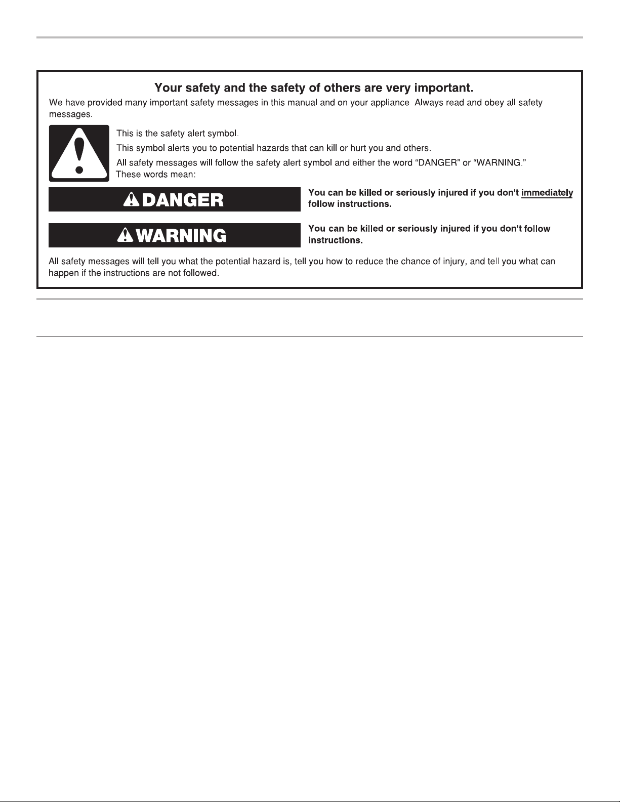
Product Dimensions - Single Ovens
B
F
A
E
27" (68.6 cm) models
3
A. 28
/4" (72.8 cm) max.
overall height
7
B. 25
/16" (64.6 cm) max.
recessed width
3
C. 26
/4" (67.9 cm)
recessed height
1
D. 23
/4" (59.1 cm) max.
recessed depth
E. 27" (68.6 cm) overall width
F. 12" (30.5 cm) from back
of control panel to start
of strain relief
G. 48" (121.9 cm) flexible
conduit length
30" (76.2 cm) models
3
A. 28
/4" (72.8 cm) max.
overall height
1
B. 28
/2" (72.4 cm) max.
recessed width
3
C. 26
/4" (67.9 cm)
recessed height
1
D. 23
/4" (59.1 cm) max.
recessed depth
E. 30" (76.2 cm) overall width
F. 12" (30.5 cm) from back
of control panel to start
of strain relief
G. 48" (121.9 cm) flexible
conduit length
C
D
3
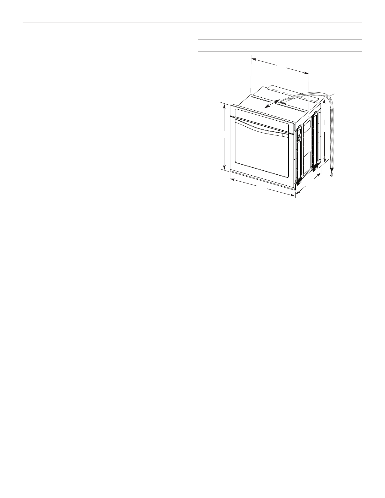
Cabinet Dimensions - Single Ovens
B
C
Single Oven Undercounter (Without Cooktop Installed Above)
A
E
Single Ovens Installed in Cabinet
A
B
D
F
G
27" (68.6 cm) models
A. 27" (68.6 cm) min.
cabinet width
1
B. 1
/2" (3.8 cm) min. top
of cutout to underside
of countertop
1
C. 5
/4" (13.3 cm) bottom
of cutout to floor
1
D. 25
/2" (64.8 cm)
cutout width
E. 28" (71.2 cm) min.
cutout height
D
30" (76.2 cm) models
A. 30" (76.2 cm) min.
cabinet width
1
B. 1
/2" (3.8 cm) min. top
of cutout to underside
of countertop
1
C. 5
/4" (13.3 cm) bottom
of cutout to floor
1
D. 28
/2" (72.4 cm)
cutout width
E. 28" (71.2 cm) min.
cutout height
E
C
27" (68.6 cm) models
A. 27" (68.6 cm) min.
cabinet width
B. 1" (2.5 cm) top of
cutout to bottom of
upper cabinet door
C. 32" (81.3 cm) bottom
of cutout to floor
1
D. 25
/2" (64.8 cm)
cutout width
1
E. 1
/2" (3.8 cm) min.
bottom of cutout to
top of cabinet door
F. 28" (71.2 cm)*
recommended
cutout height
G. 24" (60.7 cm) cutout
depth
30" (76.2 cm) models
A. 30" (76.2 cm) min.
cabinet width
B. 1" (2.5 cm) top of
cutout to bottom of
upper cabinet door
C. 32" (81.3 cm) bottom of
cutout to floor
1
D. 28
/2" (72.4 cm)
cutout width
1
E. 1
/2" (3.8 cm) min.
bottom of cutout to
top of cabinet door
F. 28" (71.2 cm)*
recommended
cutout height
G. 24" (60.7 cm) cutout
depth
* NOTE: The cutout height can be between 2615/16" and 297/16"
(68.4 cm and 74.8 cm) for single ovens.
4
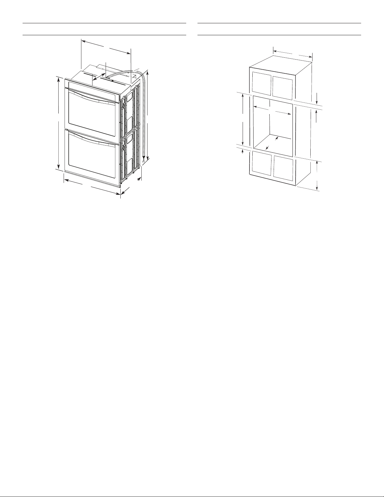
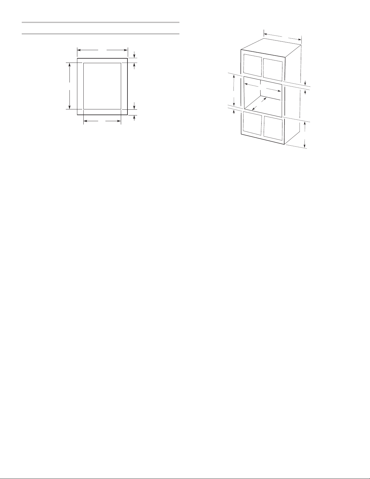
Product Dimensions - Double Ovens Cabinet Dimensions - Double Ovens
A
E
27" (68.6 cm) models
3
A. 51
/16" (130.0 cm)
max. overall height
7
B. 25
/16" (64.6 cm)
max. recessed width
13
C. 48
/16" (124.0 cm)
recessed height
1
D. 23
/4" (59.1 cm) max.
recessed depth
E. 27" (68.6 cm) overall width
F. 12" (30.5 cm) from back
of control panel to start
of strain relief
G. 66" (167.6 cm) flexible
conduit length
B
G
F
C
D
30" (76.2 cm) models
3
A. 51
/16" (130.0 cm) max.
overall height
1
B. 28
/2" (72.4 cm) max.
recessed width
13
C. 48
/16" (124.0 cm)
recessed height
1
D. 23
/4" (59.1 cm) max.
recessed depth
E. 30" (76.2 cm) overall width
F. 12" (30.5 cm) from back
of control panel to start
of strain relief
G. 66" (167.6 cm) flexible
conduit length
Double Ovens Installed in Cabinet
D
F
G
E
27" (68.6 cm) models
A. 27" (68.6 cm) min.
cabinet width
B. 1" (2.5 cm) top of
cutout to bottom of
upper cabinet door
3
C. 14
/4" (37.5 cm) bottom
of cutout to floor is
recommended.
4-143/4" (10.2-37.5 cm)
bottom of cutout to floor
is acceptable.
1
D. 25
/2" (64.8 cm)
cutout width
1
E. 1
/2" (3.8 cm) min.
bottom of cutout to
top of cabinet door
1
F. 50
/4" (127.6 cm)*
recommended cutout height
G. 24" (60.7 cm) cutout depth
30" (76.2 cm) models
A. 30" (76.2 cm) min.
B. 1" (2.5 cm) top of
C. 14
D. 28
E. 1
F. 50
G. 24" (60.7 cm) cutout depth
A
B
C
cabinet width
cutout to bottom of
upper cabinet door
3
/4" (37.5 cm) bottom
of cutout to floor is
recommended.
4-143/4" (10.2-37.5 cm)
bottom of cutout to floor is
acceptable.
1
/2" (72.4 cm)
cutout width
1
/2" (3.8 cm) min.
bottom of cutout to
top of cabinet door
1
/4" (127.6 cm)*
recommended cutout height
* NOTE: The cutout height can be between 487/8" and 523/16"
(124.1 cm and 132.6 cm) for double ovens.
5
Electrical Requirements
If codes permit and a separate ground wire is used, it is
recommended that a qualified electrical installer determine
that the ground path and the wire gauge are in accordance
with local codes.
Check with a qualified electrical installer if you are not
sure the oven is properly grounded.
This oven must be connected to a grounded metal,
permanent wiring system.
Be sure that the electrical connection and wire size are
adequate and in conformance with the National Electrical
Code, ANSI/NFPA 70 — latest edition or CSA Standards C22.
1-94, Canadian Electrical Code, Part 1 and C22.2 No.
O-M91 — latest edition, and all local codes and ordinances.
A copy of the above code standards can be obtained from:
National Fire Protection Association
1 Batterymarch Park
Quincy, MA 02169-7471
CSA International
8501 East Pleasant Valley Road
Cleveland, OH 44131-5575
Electrical Connection
To properly install your oven, you must determine the type
of electrical connection you will be using and follow the
instructions provided for it here.
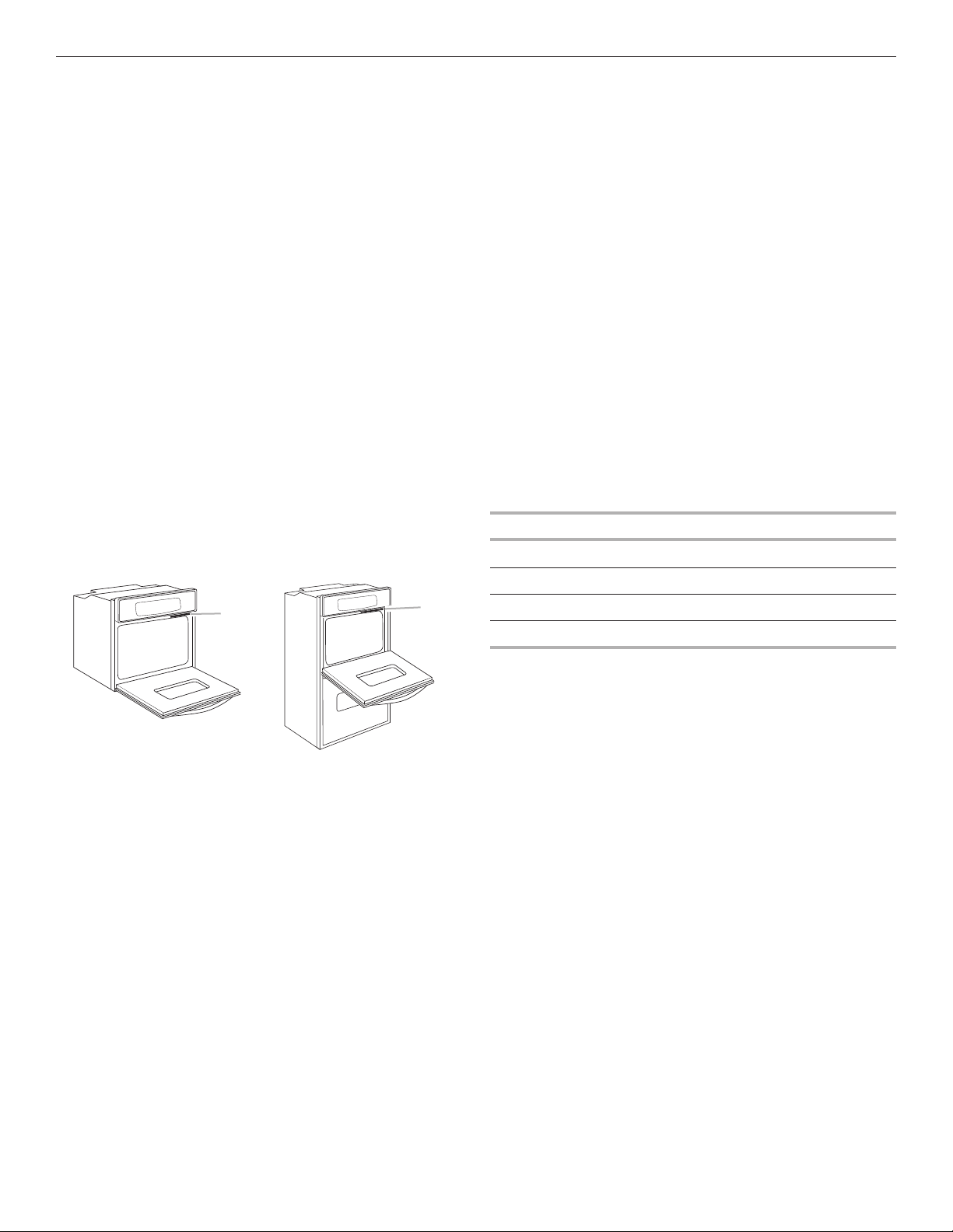
■ Oven must be connected to the proper electrical voltage and
frequency as specified on the model/serial/rating plate. The
model/serial/rating plate is located under the control panel
on single ovens and under the control panel on the upper
oven cavity on double ovens. See the following illustrations.
■ Models rated from 7.3 to 9.6 kW at 240 volts (5.4 to 7.4 kW
at 208 volts) require a separate 40-amp circuit. Models
rated at 4.8 kW and below at 240 volts (3.6 kW and below
at 208 volts) require a separate 20-amp circuit.
■ A circuit breaker is recommended.
■ Connect directly to the circuit breaker box (or fused
disconnect) through flexible, armored, or nonmetallic
sheathed, copper cable (with grounding wire). See the
“Make Electrical Connection” section.
■ Flexible conduit from the oven should be connected
directly to the junction box.
■ Fuse both sides of the line.
■ Do not cut the conduit. The length of conduit provided
is for serviceability of the oven.
■ A UL Listed or CSA Approved conduit connector
must be provided.
■ If the house has aluminum wiring, follow the procedure
below:
1. Connect the aluminum wiring using special connectors
and/or tools designed and UL Listed for joining copper to
aluminum.
Follow the electrical connector manufacturer’s recommended
procedure. Aluminum/copper connection must conform with
local codes and industry accepted wiring practices.
Voltage Single Double
240 VAC 4.0 kW 8.0 kW
208 VAC 3.0 kW 6.0 kW
Single Oven
A. Model/serial/rating plate
A
Double Oven
A. Model/serial/rating plate
A
240 VAC 16.7 A 33.3 A
208 VAC 14.4 A 28.8 A
6
 Loading...