


MULLION EVAPORATOR DESIGN
CONSUMER SERVICES TECHNICAL
ORPORATION
EDUCATION GROUP PRESENTS
AM-4
APARTMENT MAINTENANCE SERIES
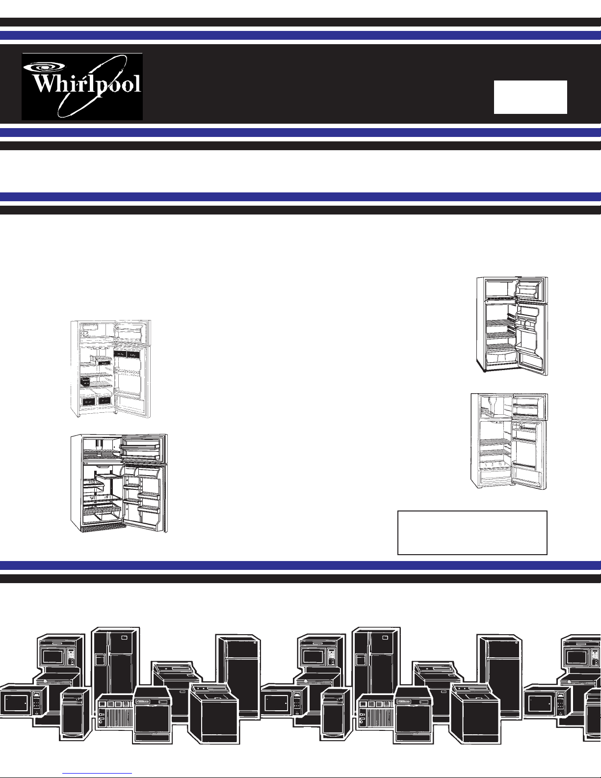
TOP-MOUNT
REFRIGERATOR/FREEZERS
“MULLION EVAPORATOR
DESIGN”
“OLD DESIGN”
14 cu. ft.
12 cu. ft.
“MID-LINE DESIGN”
16 thru 22 cu. ft.
“NEW DESIGN”
14 cu. ft.
Job Aid
Part No. 4322309
I
INTRODUCTION
This Job Aid,
4322309) has been compiled to provide the most recent information on design, features, operation,
troubleshooting and repair procedures of 12 through 22 cu. ft. top-mount refrigerator/freezers.
Four distinct series of top-mount refrigerator/freezers will be covered. See Page V for more details:
1) 12 cu. ft. “Mullion Evaporator Design” - These units are available as Roper Brand only
and have the evaporator located in the mullion divider between the freezer and refrigerator
sections. There are louvers located at the front of the freezer floor.
1) 14 cu. ft. “Old Design” - These units were manufactured through the early part of 1997
and are equipped with electric mullion heaters. There is an escutcheon box at the upper
rear of the freezer section with louvers across the top of the box.
2) 14 cu. ft. “New Design” - These units were manufactured from 1993 to the present and are
currently designated Model “F” and are equipped with heat loops and a stack condenser.
There is an air tower located on the back wall of the freezer with horizontal louvers on the
sides of the tower.
3) 16, thru 22 cu. ft. “Mid-Line Design” - These units were manufactured from 1994 to the
present and are equipped with heat loops and forced air condensers. There is an air tower
located on the back wall of the freezer with a curved face and vertical louvers.
This Job Aid is not intended to replace or substitute for the Service Manuals, Use and Care Guides
or Tech Sheets associated with any of the models covered. Particular attention should be given to
the Tech Sheets provided with each individual unit for the latest engineering design changes.
“APARTMENT MAINTENANCE SERIES: Servicing Refrigerators,”
(Part Number LIT
GOALS AND OBJECTIVES
The goal of this Job aid is to provide detailed information that will enable the service technician to
properly diagnose malfunctions and repair 12 through 22 cu. ft. top-mount refrigerator/freezers.
The objectives of this Job Aid are:
The service technician will --
• Understand proper safety precautions.
• Successfully troubleshoot and diagnose malfunctions.
• Successfully perform necessary repairs.
• Successfully return the unit to proper operational status.
TO THE INSTRUCTOR/INDEPENDENT STUDENT
At the end of certain sections of this Job Aid you will find a
You will need a pencil or pen and in some cases two “Hi-Light” markers to complete these exercises. Certain exercises may require that service procedures be performed, if an appropriate
appliance is available.
“Confirmation of Learning Exercise.”
CORPORATION
WHIRLPOOL CORPORATION ASSUMES NO RESPONSIBILITY
FOR ANY REPAIRS MADE ON OUR PRODUCTS BY ANYONE
OTHER THAN AUTHORIZED SERVICE TECHNICIANS.
© 1998 Whirlpool Corporation, Benton Harbor, MI 49022
II

TABLE OF CONTENTS
INTRODUCTION.............................................................................................II
GOALS AND OBJECTIVES ........................................................................... II
TO THE INSTRUCTOR/INDEPENDENT STUDENT ...................................... II
TABLE OF CONTENTS.................................................................................III
SAFETY ........................................................................................................ IV
PRODUCT IDENTIFICATION ........................................................................ V
SECTION ONE - SECTION ONE -
SECTION ONE - Mullion Evaporator Design 12 cu. ft. Top-Mount
SECTION ONE - SECTION ONE -
INSTALLATION CONSIDERATIONS .......................................................1
THEORY OF OPERATION........................................................................ 4
COMPONENT ACCESS............................................................................ 6
WIRING DIAGRAMS and STRIP CIRCUITS .......................................... 10
SECTION TWO SECTION TWO
SECTION TWO - Old Design 14 cu. ft. Top-Mount
SECTION TWO SECTION TWO
INSTALLATION CONSIDERATIONS .....................................................13
THEORY OF OPERATION......................................................................17
COMPONENT ACCESS..........................................................................19
WIRING DIAGRAMS and STRIP CIRCUITS .......................................... 24
SECTION THREE SECTION THREE
SECTION THREE - New Design 14 cu. ft. Top-Mount
SECTION THREE SECTION THREE
INSTALLATION CONSIDERATIONS .....................................................33
THEORY OF OPERATION......................................................................37
COMPONENT ACCESS..........................................................................39
WIRING DIAGRAMS and STRIP CIRCUITS .......................................... 46
SECTION FOUR SECTION FOUR
SECTION FOUR - Mid-Line Design 16 & 22 cu. ft. Top-Mount
SECTION FOUR SECTION FOUR
INSTALLATION CONSIDERATIONS .....................................................49
THEORY OF OPERATION......................................................................53
COMPONENT ACCESS..........................................................................55
WIRING DIAGRAMS and STRIP CIRCUITS .......................................... 64
SECTION FIVE - TROUBLESHOOTING AND DIAGNOSISSECTION FIVE - TROUBLESHOOTING AND DIAGNOSIS
SECTION FIVE - TROUBLESHOOTING AND DIAGNOSIS
SECTION FIVE - TROUBLESHOOTING AND DIAGNOSISSECTION FIVE - TROUBLESHOOTING AND DIAGNOSIS
GENERAL ...............................................................................................71
SEALED SYSTEM DIAGNOSIS .............................................................72
TROUBLESHOOTING CHART...............................................................73
TYPICAL TESTING PROCEDURES.......................................................80
SECTION SIX - TECH TIPSSECTION SIX - TECH TIPS
SECTION SIX - TECH TIPS
SECTION SIX - TECH TIPSSECTION SIX - TECH TIPS
REPLACING ELECTROMECHANICAL TIMERS ...................................89
DOOR GASKET REPLACEMENT ..........................................................90
SERVICING THE ADAPTIVE DEFROST CONTROL ............................. 9 4
SERIAL AND MODEL NUMBER DESIGNATORS ................................. 9 5
III
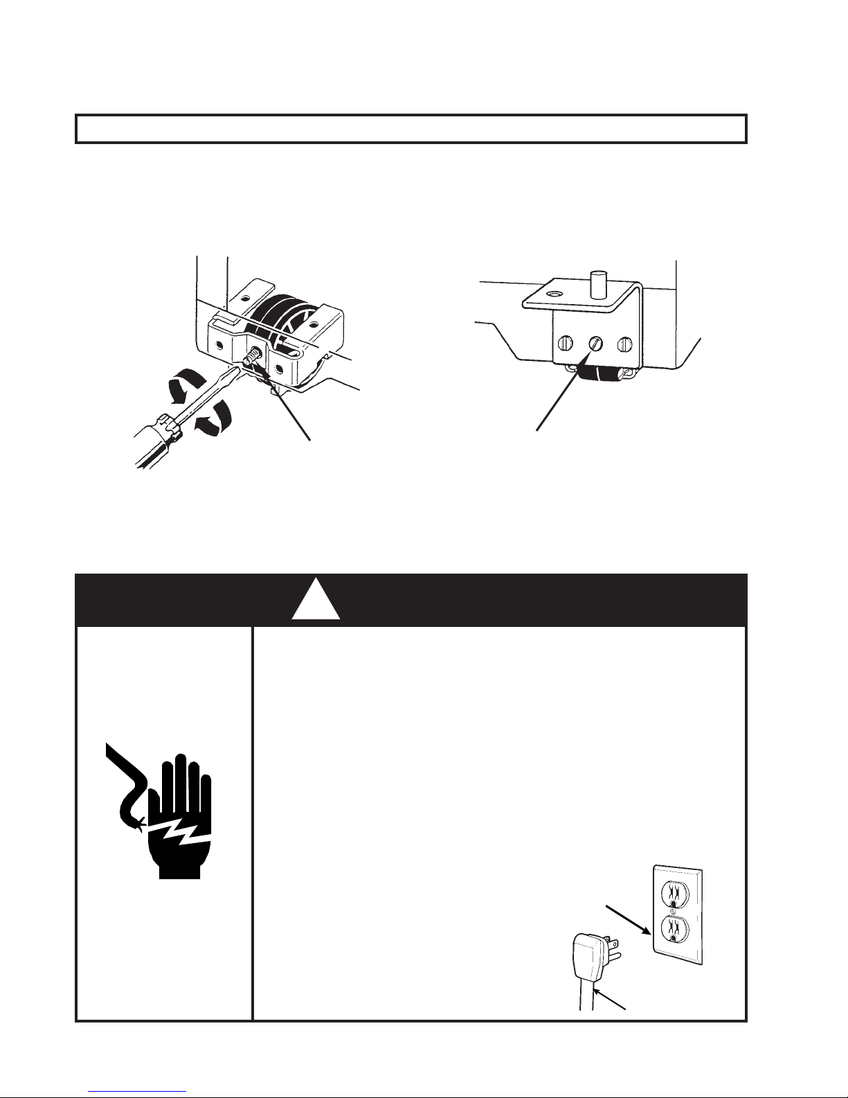
SAFETY
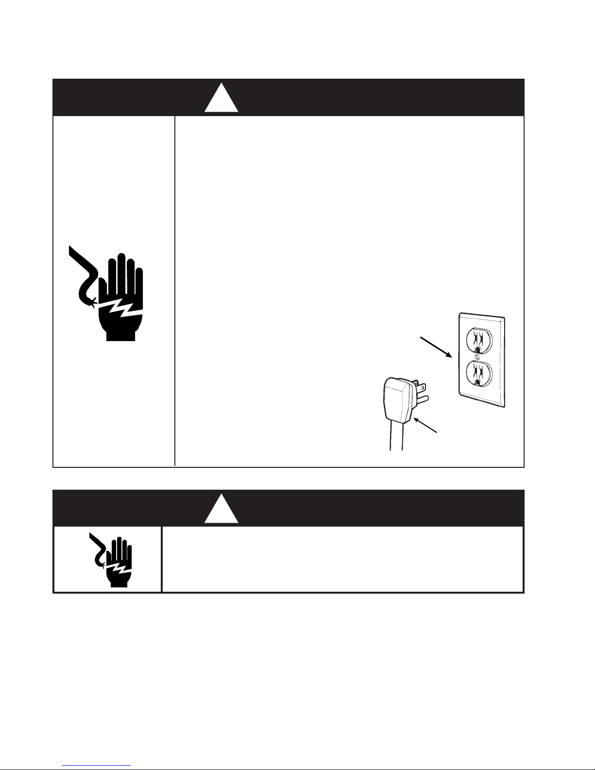
! WARNING
To avoid the risk of electrical shock,
property damage, personal injury or death:
• The power cord must be plugged into a 3-prong grounding-type
wall receptacle, grounded in accordance with the National
Electrical Code, ANSI/NFPA 70 - latest edition, and local codes
and ordinances.
• It is the personal responsibility of the consumer to have a proper
3-prong wall receptacle installed by a qualified electrician.
• DO NOT, UNDER ANY CIRCUMSTANCES, REMOVE THE
POWER CORD GROUNDING PRONG.
• A separate adequately fused and grounded circuit should be
available for this appliance.
• Do not remove any grounding wires
from individual components while
servicing, unless the component is
to be removed and replaced.
extremely
grounding wires when components
are replaced.
important to replace all
It is
Grounding
Type
Wall
Receptacle
Power Supply
Cord
with 3-Prong
Grounding Plug
Disconnect the electrical power before servicing any components .
! WARNING
ELECTRIC SHOCK HAZARD
Failure to do so can result in death or electrical shock.
IV
PRODUCT IDENTIFICATION
Four distinct series of top-mount refrigerator/freezers will be covered in the Job Aid. Each series can
be identified by a number of distinguishing features:
A) Air circulation in the freezer compartment
B) Type of condenser
C) Location of the Evaporator
D) Method of outside condensation control
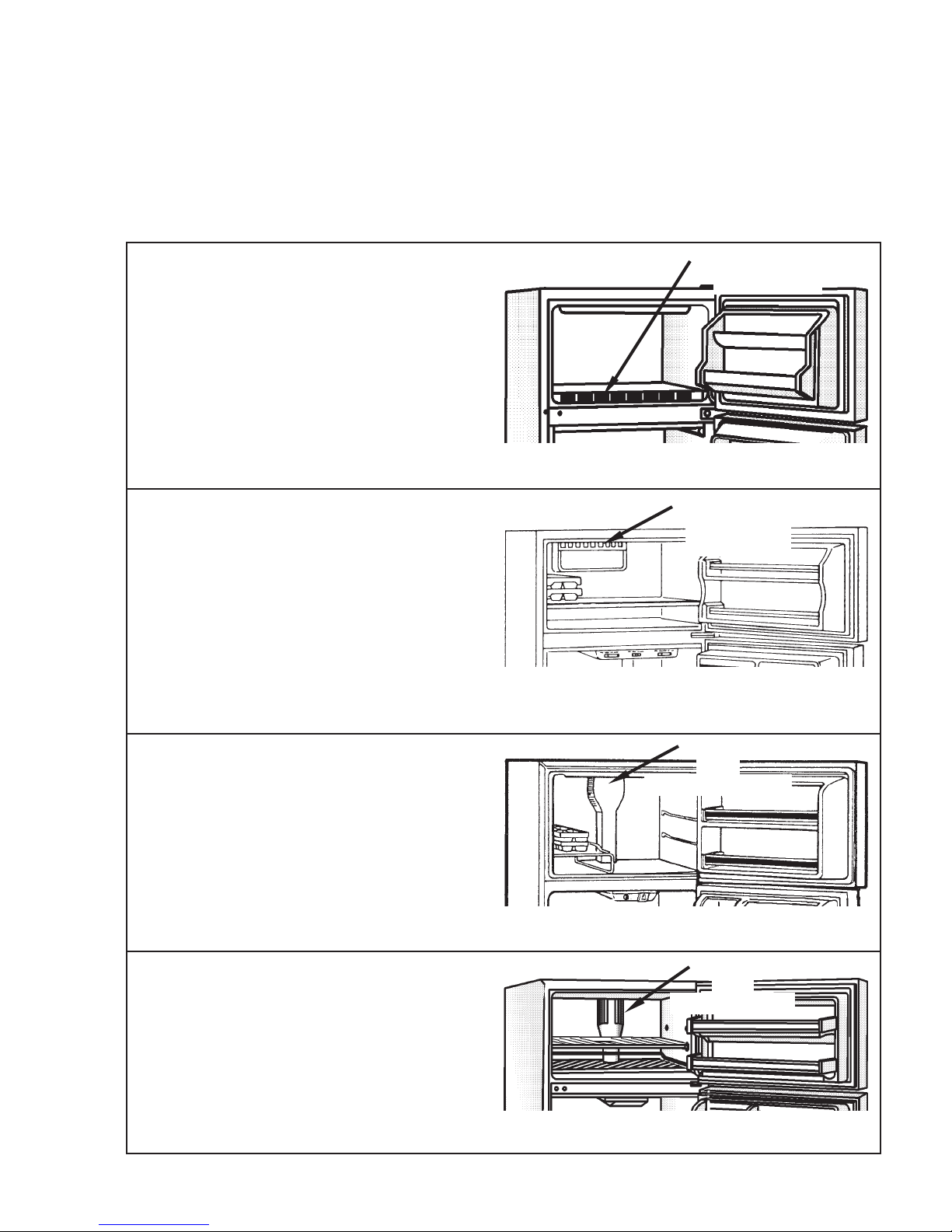
12 cu. ft. “Mullion Evaporator Design” -
Distinguishing Characteristics:
• Air return louvers located at the front of
the freezer floor.
• A stack condenser on the back of the
unit.
• Has heat loop mullion and stile heat.
• Evaporator located in the divider between the freezer and refrigerator sections.
• Roper brand only
12 & 14 cu. ft. “Old Design” -
Distinguishing Characteristics:
• Air discharge louvers located at the top
rear of the freezer section.
• A stack condenser on the back of the
unit.
• Has electric mullion and stile heaters.
• Evaporator vertically mounted behind
rear panel of freezer compartment.
• May be equipped with Adaptive Defrost
Control.
Louvers at Front of
Freezer Floor
Component Access - Section One, page 6.
Wiring Diagram - Section One, page 10.
Louvers Across
Top Rear
Component Access - Section Two, page 19.
Wiring Diagram - Section Two, page 24.
Adaptive Defrost Control - Section Six, page 92.
14 cu. ft. “New Design” -
Distinguishing Characteristics:
• Air tower at the rear of the freezer section
with horizontal louvers.
• Has heat loop mullion and stile heat.
• A stack condenser on the back of the
unit.
• Model “F” designation
• Manufactured from 1993 to present
16, thru 22 cu. ft. “Mid-Line Design” -
Distinguishing Characteristics:
• Air tower at the rear of the freezer section
with vertical louvers.
• Has heat loop mullion and stile heat.
• A forced air condenser at the bottom of
the unit.
• Manufactured from 1994 to present.
Air Tower
with
Horizontal Louvers
Component Access - Section Three, page 36.
Wiring Diagram - Section Three, page 46.
Air Tower
with
Vertical Louvers
Component Access - Section Four, page 55.
Wiring Diagram - Section Four, page 64.
V

-- NOTES --
VI
Section One
Mullion Evaporator Design
12 cu. ft. Top-Mount
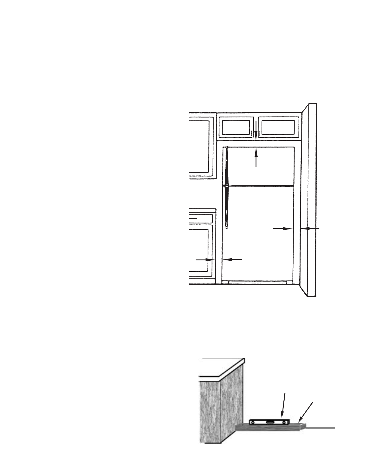
INSTALLATION CONSIDERATIONS
Minimum Clearance
Measure the opening at the location in which the refrigerator/freezer is to be installed and make
sure the following minimum clearance dimensions are followed.
Top: At least 3” (7.5cm) clearance between
the overhead cabinet and the refrigerator/
freezer top. (Dimension A)
Sides: At least 1” (2.5cm) clearance on each side
of the refrigerator/freezer. (Dimension B)
(Fig. 1)
Back: At least ½” (1.25cm) clearance between
the condenser (“Old Design” 14 cu. ft.
Top-Mount) and the wall.
(Fig. 1)
A
B
B
Fig 1
Leveling the Refrigerator/Freezer
It is critical that the refrigerator/freezer be properly leveled. Both the back and front of the unit should
be carefully leveled before it is turned on.
1. Place a board across the rear of the installed position and set a level on the board.
2. Place shims where the rear rollers will sit to level the board.
3. Remove the board and leave the shims in place.
4. Place the unit in its installed position.
Level
(Fig. 2)
Board
MULLION EVAPORATOR DESIGN 12 cu. ft. Top-Mount
Fig. 2
1

Once the unit is located in the final installed location and the rear of the unit is level, proceed to
level the front.
NOTE: Using a spirit level, the front of the unit should be ½ bubble higher than the back.
1. Use a flat blade screwdriver to rotate the front roller leveling screws in the appropriate direction
to level the unit side to side.
2. Use a level and check to make sure the rollers are set so the unit is level side to side and ½
bubble higher in front.
Fig. 3
(Fig. 3 & 4))
VIEW OF ROLLER WITH HINGE IN PLACEVIEW OF ROLLER WITH NO HINGE
LOWER
RAISE
Leveling
Screw
Fig. 4
Leveling
Screw
Electrical Requirements
A 115 V, 60 Hz, 15 TO 20 Amp fused circuit utilizing a 3-wire grounding receptacle meeting all
national and local electrical codes is required. It is recommended that a separate circuit serving
only this appliance be provided.
! WARNING
To avoid the risk of electrical shock,
property damage, personal injury or death:
• The power cord must be plugged into a 3-prong grounding-type
wall receptacle, grounded in accordance with the National
Electrical Code, ANSI/NFPA 70 - latest edition, and local codes
and ordinances.
• It is the personal responsibility of the consumer to have a proper
• DO NOT, UNDER ANY CIRCUMSTANCES, REMOVE THE
• Do not remove any grounding wires
MULLION EVAPORATOR DESIGN 12 cu. ft. Top-Mount
3-prong wall receptacle installed by a qualified electrician.
POWER CORD GROUNDING PRONG.
Grounding Type
from individual components while
servicing, unless the component is
to be removed and replaced.
extremely
grounding wires when components
are replaced.
important to replace all
2
It is
Receptacle
3-Prong
Grounding Plug
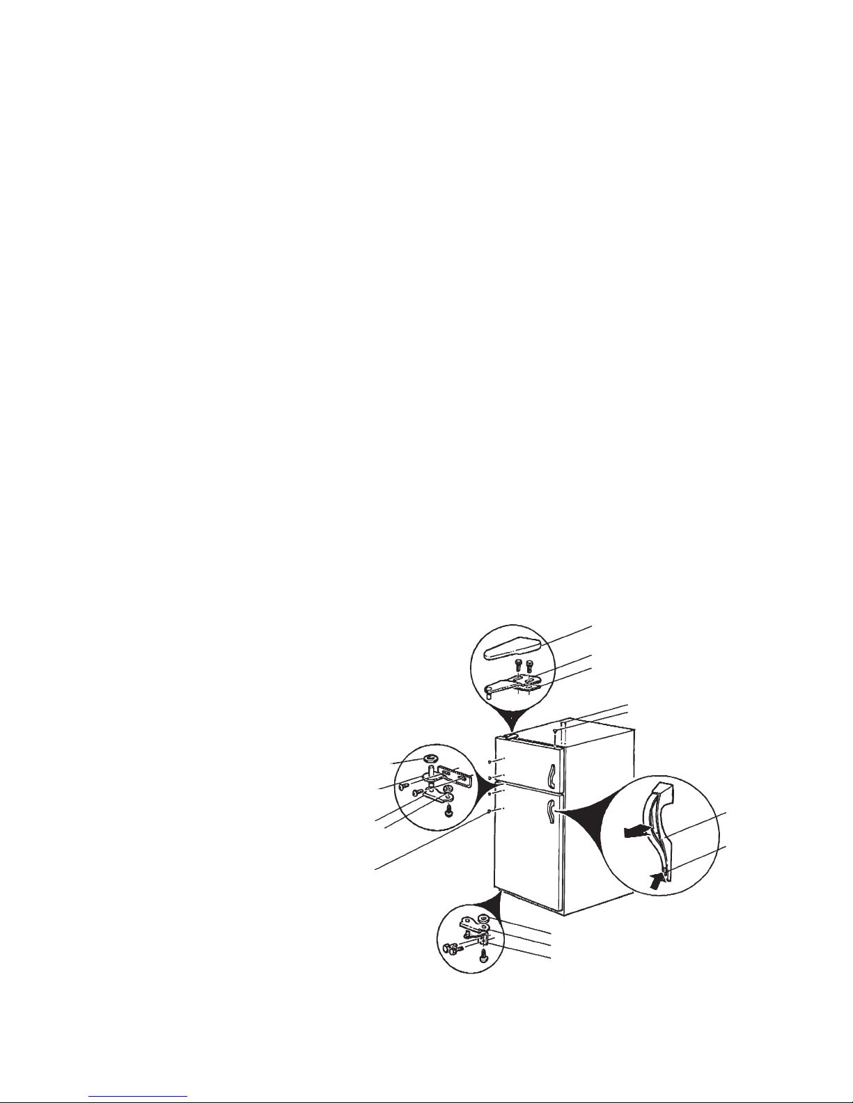
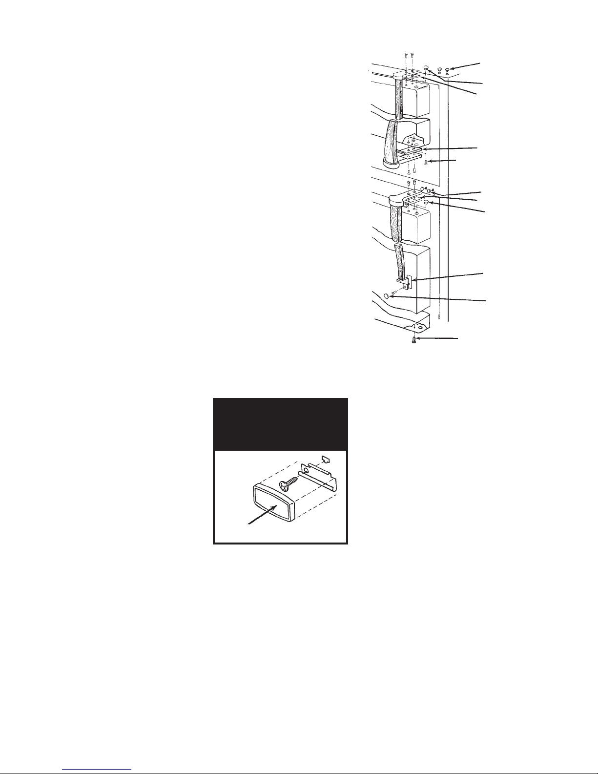
DOOR SWING REVERSAL
1. Open the refrigerator door and remove the toe panel at the bottom of the unit.
2. Remove the top hinge.
(Fig. 5)
3. Remove the freezer door.
4. Remove the center hinge.
(Fig. 5)
5. Remove the refrigerator door.
6. Remove the bottom hinge.
7. Lay the freezer door on a flat protected surface and remove the door handle.
(Fig. 5)
(Fig. 5)
8. Reinstall the freezer door handle on the opposite side of the door.
9. Lay the refrigerator door on a flat protected surface and remove the door handle.
(Fig. 5)
10. Reinstall the refrigerator door handle on the opposite side of the door.
11. Move the bottom hinge to the opposite side of the cabinet and reinstall it.
12. Set the refrigerator door on the bottom hinge and close the door to keep it in place.
13. Reinstall the center hinge.
14. Set the freezer door in the center hinge and close the door to keep it in place.
15. Reinstall the top hinge.
16. To align the refrigerator door:
a) DO NOT ADJUST THE BOTTOM HINGE. Use the bottom hinge as an establishing point.
b) Loosen the center hinge
(Figs. 5)
and align the refrigerator door with the cabinet edge.
c) Tighten the center hinge.
17. To align the freezer door:
a) If the refrigerator door is properly aligned,
DO NOT ADJUST THE CENTER HINGE.
b) Loosen the top hinge
(Fig. 5)
the top of the freezer door with the top
of the cabinet.
c) Tighten the top hinge.
Plastic Washer
Center Hinge
Door Stop
Fiber Washer
Handle
Hole Plug
and align
Cover
Top Hinge
Shim
Hinge Hole Plug
Hinge Bushing
Plug
Handle
Handle
Insert
Fiber Washer
Door Stop
Bottom
Hinge
MULLION EVAPORATOR DESIGN 12 cu. ft. Top-Mount
Fig. 5
3
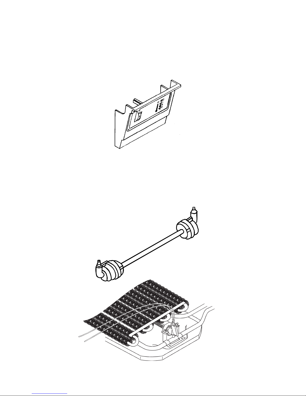
THEORY OF OPERATION
TEMPERATURE CONTROL
Temperature control is provided by an adjustable thermostat located behind the control panel escutcheon in the refrigerator compartment.
both the freezer section and the refrigerator section. There is no damper to adjust air flow between the
two sections.
(Fig. 6)
DEFROST HEATER
This thermostat influences the temperatures in
Fig. 6
The defrost heat is provided by a quartz tube radiant heater
coils in the divider mullion.
must be taken when handling this heater element to insure that the quartz tube does not come in
contact with any contaminants such as skin oil, perspiration or lubricants. Always wear a pair of clean
gloves when handling the defrost heater assembly. Contaminating the surface of the quartz tube will
cause premature failure.
(Fig. 8)
A coiled wire element is encased in a quartz tube. Special care
Fig. 7
(Fig. 7)
lying underneath the evaporator
MULLION EVAPORATOR DESIGN 12 cu. ft. Top-Mount
Fig. 8
4
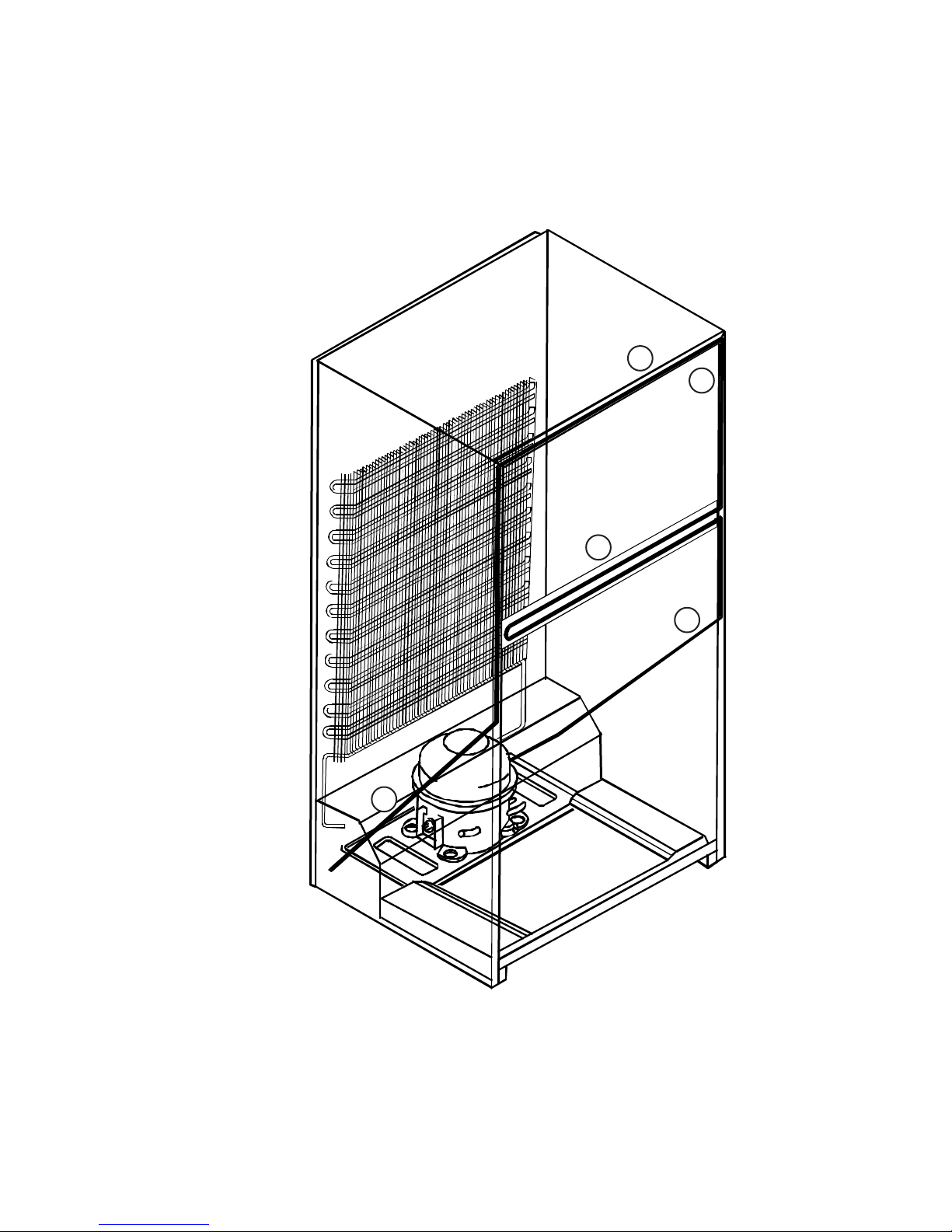
HEAT LOOP ROUTING
The heat loop is routed from the condenser outlet up the right side of the cabinet to the right stile (A).
It then loops through the mullion between the refrigerator and freezer sections (B) and up around the
freezer section (C & D), where it then returns to component compartment ( E) and connects to the
sealed system at the filter-drier.
(Fig. 9)
D
C
B
E
A
HEAT LOOP
Fig. 9
MULLION EVAPORATOR DESIGN 12 cu. ft. Top-Mount
5
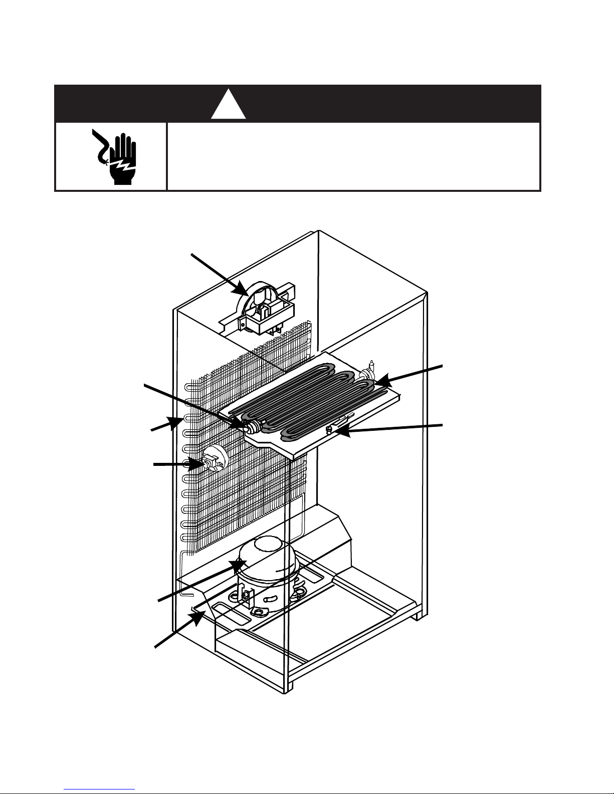
COMPONENT ACCESS
Disconnect the electrical power before servicing any components.
EVAPORATOR
FAN
! WARNING
ELECTRIC SHOCK HAZARD
Failure to do so can result in death or electrical shock.
DEFROST
HEATER
CONDENSER
THERMOSTAT
COMPRESSOR
DRIP PAN/
COMPRESSOR
BASE
EVAPORATOR
BI-METAL
MULLION EVAPORATOR DESIGN 12 cu. ft. Top-Mount
Fig. 10
6
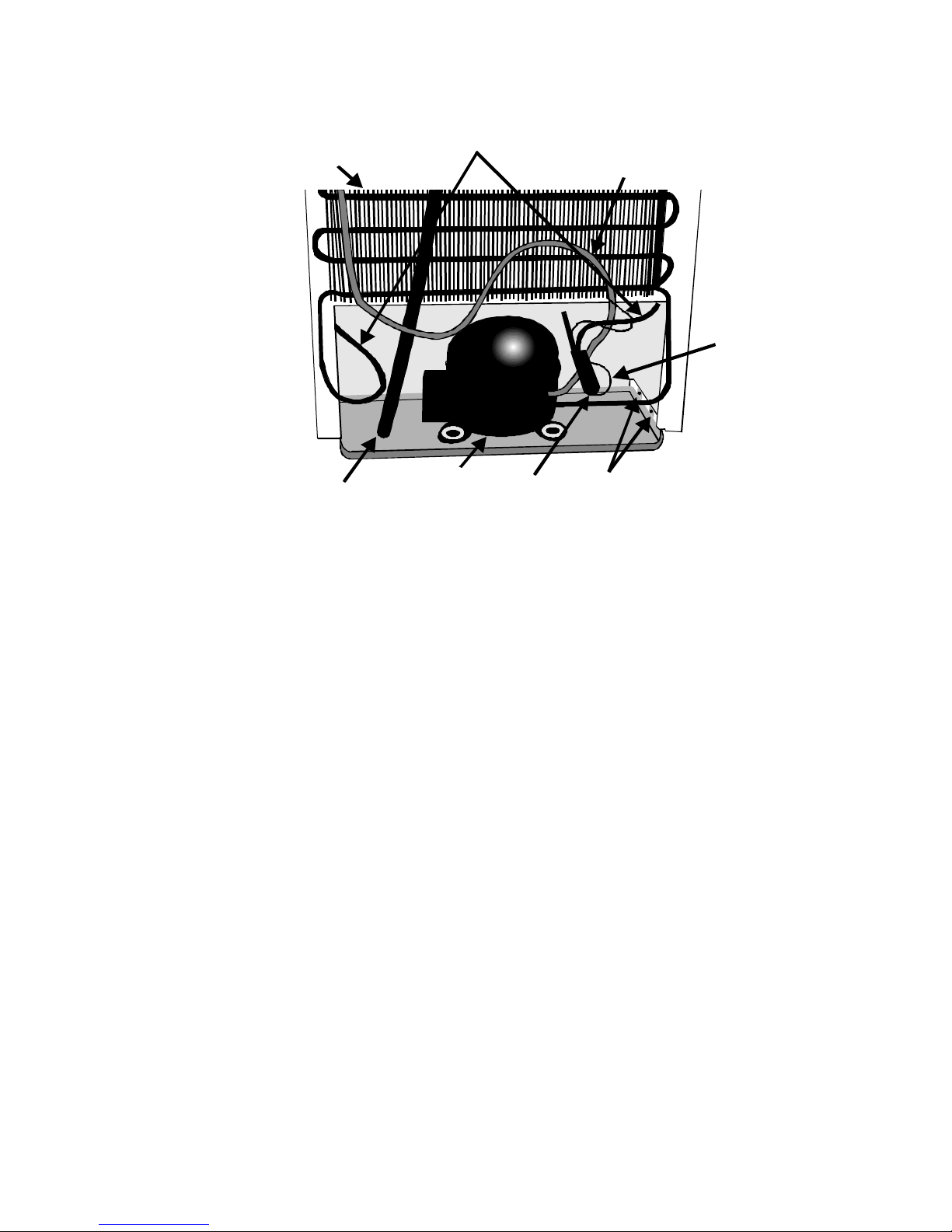
Servicing Components in the Compressor Compartment
Fig. 11
CONDENSER
DRAIN
TUBE
HEAT LOOP
COMPRESSOR
FILTER
DRIER
MOUNTING BOLTS
HEAT
EXCHANGER
CAPILLARY
TUBE
COMPONENT
TRAY
The compressor and related components are located at the bottom back of the refrigerator/freezer
in an open compartment.
DEFROST DRAIN
The drain tube from the freezer section is routed down the outside back of the cabinet underneath
the condenser to the component tray at the bottom. The component tray serves as the drain pan.
1. Remove the screws from the four (4) clips securing the condenser to the back of the cabinet
and lean the condenser away from the cabinet far enough to gain access to the drain tube.
2. Loosen the clamp securing the drain hose to the outlet on the back of the cabinet.
3. Remove the screw from the clip securing the lower portion of the drain hose to the cabinet.
4. When replacing the drain hose be sure to put a loop in it near the connection to the freezer.
The loop creates a trap which prevents warm air and moisture from migrating into the freezer
compartment.
SERVICING THE COMPRESSOR
1. Remove the four (4) screws securing the component tray to the cabinet. There are two screws
on each side of the unit.
2. Carefully slide the component tray out from the refrigerator/freezer far enough for the compressor to clear the back of the cabinet. Watch that the tubing is not kinked when sliding the tray
out.
3. Follow standard Sweep Charge Procedures for replacing the compressor.
4. Slide the component tray back into the unit and secure it with to the cabinet the four (4) screws
removed earlier.
MULLION EVAPORATOR DESIGN 12 cu. ft. Top-Mount
7
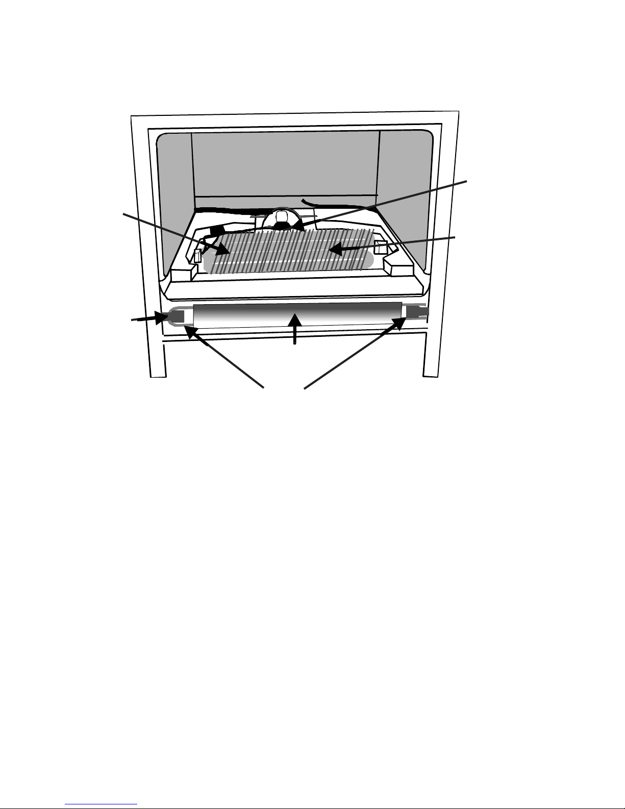
Servicing Components in the Freezer Compartment
EVAPORATOR
FAN MOTOR
EVAPORATOR
DEFROST
HEATER
(Under Evaporator)
Fig. 12
CENTER
RAIL
BRACKET
HEAT
SHIELD
HEAT
LOOP
Accessing Freezer Compartment Components
The center rail covering the mullion between the freezer and refrigerator compartments and the
freezer floor must be removed to gain access to components in the freezer compartment.
1. Remove both doors and the center hinge. Also remove the screws on the other side of the
center rail.
2. Press in on the left side of the center rail while sliding it to the left. This will release the right end
of the center rail from the cabinet.
3. Slide the center rail to the right to release the left end from the cabinet.
4. Carefully slide the freezer floor out of the freezer compartment.
5. Lift the Styrofoam evaporator housing cover and aluminum heater shield from the bottom of the
freezer compartment.
The evaporator is surrounded by Styrofoam insulation inside the compartment separator.
Servicing the Evaporator Fan Motor
1. Disconnect the two (2) wire connectors from the evaporator fan motor.
2. Remove the two (2) screws securing the evaporator fan motor bracket to the fan scroll.
3. The fan blade is pressed onto the motor shaft. The motor shaft should not extend past the fan
blade hub.
MULLION EVAPORATOR DESIGN 12 cu. ft. Top-Mount
8
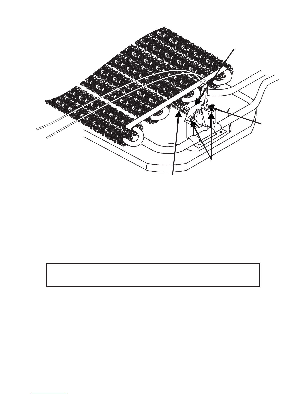
DEFROST HEATER
DRIP COVER
CONNECTOR
WIRE
Fig. 13
DEFROST
HEATER
BRACKET
TABS
Servicing the Defrost Heater
1. Disconnect the wire connectors from both ends of the defrost heater.
2. Carefully lift up on the evaporator far enough to expose the defrost heater and drip cover.
3. Carefully bend the tabs on the defrost heater mounting brackets up to release the defrost heater
drip cover and remove the drip cover.
4. Remove the defrost heater from the mounting brackets.
5. Place the new defrost heater in the mounting brackets.
NOTE: Do not touch the glass tube of the defrost heater with bare hands. Body oils
and other contaminants will cause the glass tube to break when it gets hot.
Wear a pair of clean soft gloves.
6. Reinstall the defrost heater drip cover and secure it in place by bending the mounting bracket
tabs down.
MULLION EVAPORATOR DESIGN 12 cu. ft. Top-Mount
9
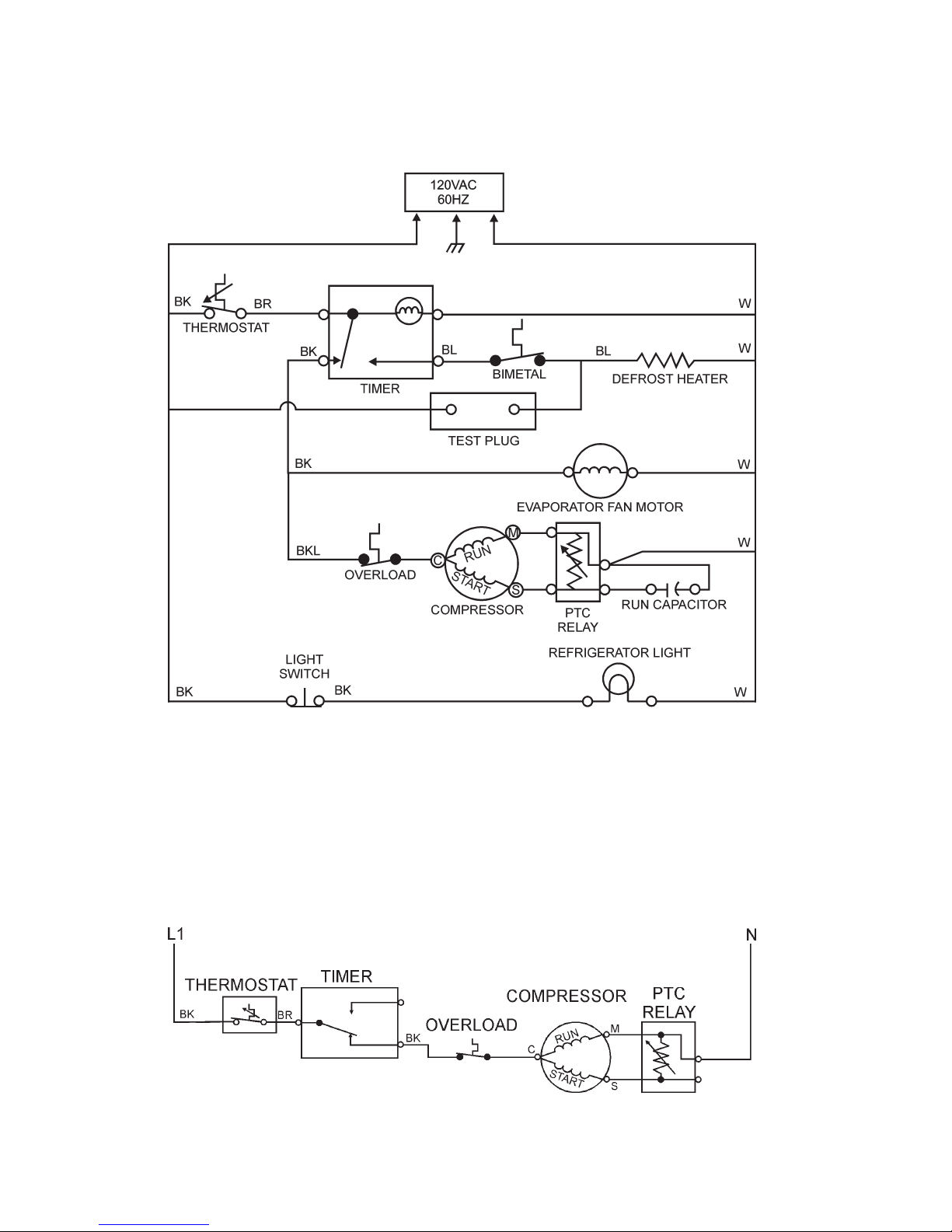
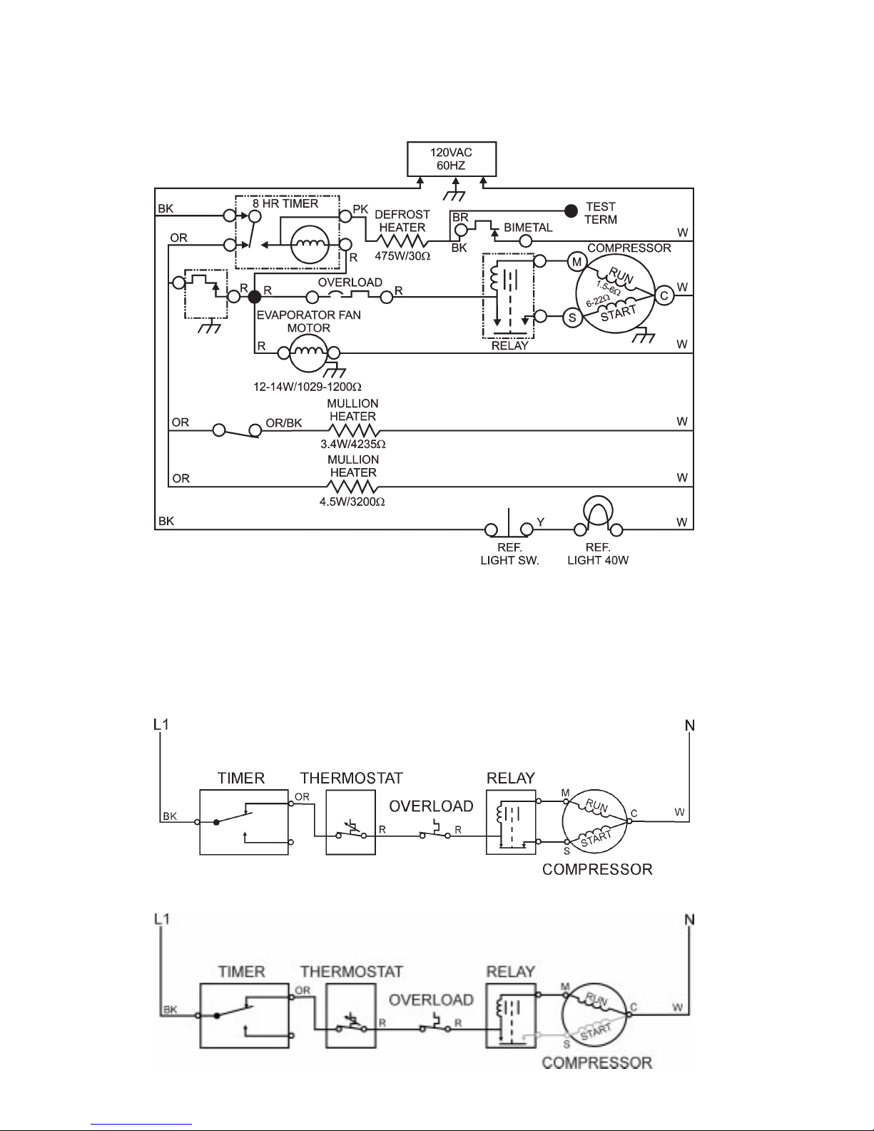
WIRING DIAGRAM
COOLING CYCLE
Compressor Circuit (at instant of start)
MULLION EVAPORATOR DESIGN 12 cu. ft. Top-Mount
STRIP CIRCUITS
10
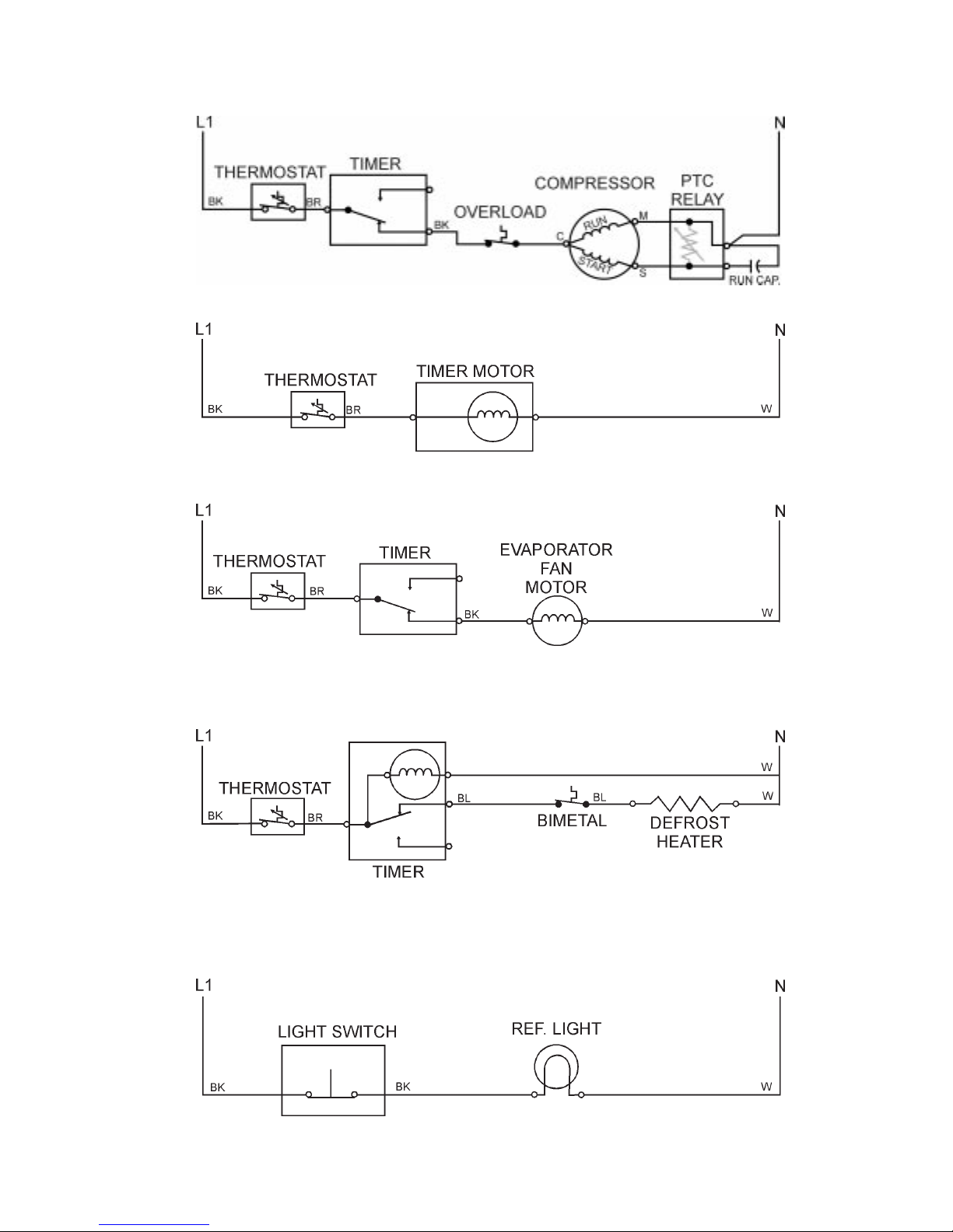
Compressor Circuit (running)
Defrost Timer Motor Circuit
Evaporator Fan Motor Circuit
DEFROST CYCLE
Defrost Timer and Defrost Heater Circuit
REFRIGERATOR LIGHT
Refrigerator Light Circuit
MULLION EVAPORATOR DESIGN 12 cu. ft. Top-Mount
11

-- NOTES --
MULLION EVAPORATOR DESIGN 12 cu. ft. Top-Mount
12

Section Two
Old Design
12 & 14 cu. ft. Top-Mount
INSTALLATION CONSIDERATIONS
Minimum Clearance
Measure the opening at the location in which the refrigerator/freezer is to be installed and make
sure the following minimum clearance dimensions are followed.
Top: At least 3” (7.5cm) clearance between
the overhead cabinet and the refrigerator/
freezer top. (Dimension A)
Sides: At least 1” (2.5cm) clearance on each side
of the refrigerator/freezer. (Dimension B)
(Fig. 14)
Back: At least ½” (1.25cm) clearance between
the condenser (“Old Design” 14 cu. ft.
Top-Mount) and the wall.
(Fig. 14)
A
B
B
Fig. 14
Leveling the Refrigerator/Freezer
It is critical that the refrigerator/freezer be properly leveled. Both the back and front of the unit should
be carefully leveled before it is turned on.
1. Place a board across the rear of the installed position and set a level on the board.
2. Place shims where the rear rollers will sit to level the board.
3. Remove the board and leave the shims in place.
4. Place the unit in its installed position.
Level
(Fig. 15)
Board
OLD DESIGN 12 & 14 cu. ft. Top-Mount
Fig. 15
13
Once the unit is located in the final installed location and the rear of the unit is level, proceed to
level the front.
NOTE: When leveling the front of the unit, the front should be ½ bubble higher than the back.
1. Use a flat blade screwdriver to rotate the front roller leveling screws in the appropriate direction
to level the unit side to side.
2. Use a level and check to make sure the rollers are set so the unit is level side to side and ½
bubble higher in front.
Fig. 16
(Fig. 16 & 17)
VIEW OF ROLLER WITH HINGE IN PLACEVIEW OF ROLLER WITH NO HINGE
LOWER
RAISE
Leveling
Screw
Fig. 17
Leveling
Screw
Electrical Requirements
A 115 V, 60 Hz, 15 TO 20 Amp fused circuit utilizing a 3-wire grounding receptacle meeting all
national and local electrical codes is required. It is recommended that a separate circuit serving
only this appliance be provided.
! WARNING
To avoid the risk of electrical shock,
property damage, personal injury or death:
• The power cord must be plugged into a 3-prong grounding-type
wall receptacle, grounded in accordance with the National
Electrical Code, ANSI/NFPA 70 - latest edition, and local codes
and ordinances.
• It is the personal responsibility of the consumer to have a proper
• DO NOT, UNDER ANY CIRCUMSTANCES, REMOVE THE
• Do not remove any grounding wires
OLD DESIGN 12 & 14 cu. ft. Top-Mount
3-prong wall receptacle installed by a qualified electrician.
POWER CORD GROUNDING PRONG.
Grounding Type
from individual components while
servicing, unless the component is
to be removed and replaced.
extremely
grounding wires when components
are replaced.
important to replace all
14
It is
Receptacle
3-Prong
Grounding Plug
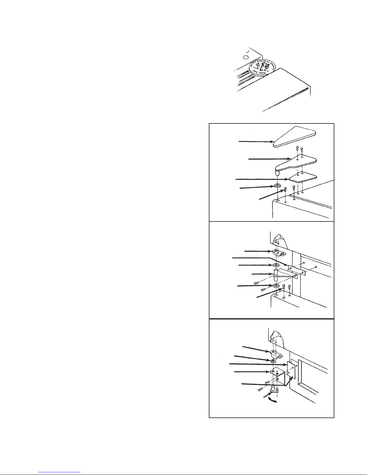
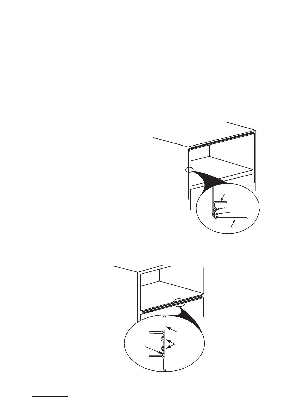
Door Alignment
Occasionally, the refrigerator or freezer doors
may need to be realigned. Evidence of improperly aligned doors includes a generally poor
appearance of the unit and/or sweating/frosting
on both the inside and outside of the cabinet
due to poor gasket seal.
1. Check for proper door gasket seal by
placing an American dime between the
inside of the door and the cabinet. The gap
should not be less than, or greater, than
then diameter of the dime (11/16”).
(Fig. 18)
2. Before making any attempt to realign the
doors by adjusting the hinges, make sure
the unit is solidly supported and level. (See
page 13 in this section on procedures to
level the unit.)
3. To align the refrigerator door:
a) DO NOT ADJUST THE BOTTOM
HINGE. Use the bottom hinge as an
establishing point.
b) Loosen the center hinge
(Figs. 19)
and align the refrigerator door with the
cabinet edge.
c) Tighten the center hinge.
4. To align the freezer door:
a) If the refrigerator door is properly
aligned, DO NOT ADJUST THE
CENTER HINGE.
b) Loosen the top hinge
(Fig. 19)
and
align the top of the freezer door with
the top of the cabinet.
c) Tighten the top hinge.
Fig. 18
TOP HINGE
Cover
Top Hinge
Shim
Spacer
Sealing Screws
CENTER HINGE
Door Stop
Shim
Spacer
Center Hinge
Spacer
Sealing Screws
5. Check the door gasket gap on the hinged
side of the door. The gap should be straight
and even and the proper width (11/16” or
the diameter of an American dime) from
the top hinge to the bottom hinge.
a) If the gap is uneven or too narrow or if
the doors hit each other when opened
together, add shims at the center
hinge to even out the gap.
b) If the gap is uneven or too wide, or the
space between the refrigerator and
freezer door widens when opened
together, remove shims at the center
hinge to even out the gap.
OLD DESIGN 12 & 14 cu. ft. Top-Mount
BOTTOM HINGE
Door Stop
Spacer
Shim
Bottom
Hinge
Tap Plate
(in cabinet)
Moveable Hinge
Pin
(left hole for left swing)
Fig. 19
15
Door Swing Reversal
Cap
1. Open the refrigerator door and remove the toe
panel at the bottom of the unit.
2. Remove the top hinge.
(Fig. 20)
3. Remove the freezer door.
4. Remove the center hinge.
(Fig. 20)
5. Remove the refrigerator door.
6. Remove the bottom hinge.
(Fig. 20)
7. Lay the freezer door on a flat protected surface
and remove the door handle.
(Fig. 20)
8. Reinstall the freezer door handle on the opposite side of the door.
9. Lay the refrigerator door on a flat protected
surface and remove the door handle.
(Fig. 20)
10. Reinstall the refrigerator door handle on the
opposite side of the door.
11. Move the bottom hinge to the opposite side of
the cabinet and reinstall it.
12. Set the refrigerator door on the bottom hinge
and close the door to keep it in place.
13. Reinstall the center hinge.
14. Set the freezer door in the center hinge and
close the door to keep it in place.
15. Reinstall the top hinge.
16. Align the doors. (See procedures on page 15.)
Cap
Spacer
Spacer
Screw
Cap
Spacer
Cap
Spacer
Cap
Screw
Fig. 11
14, 16 & 18 cu. ft. Top-Mount
Cover for Refrigerator
Door Handle
Cover
Fig. 9
OLD DESIGN 12 & 14 cu. ft. Top-Mount
16
THEORY OF OPERATION
MULLION AND STILE HEATERS
All refrigerators have a tendency to sweat around the door openings due to the differences between
the ambient room temperature and the cold compartments of the refrigerator. On “Old Design” units
low-wattage resistance heaters are installed to the front flange area of the cabinet to help prevent
sweating.
Stile Heaters
Stile heaters are foil-wrapped resistance-type heating elements in the 5 - 30 watt range. These
heating elements fit on the inside of the cabinet flange across the top of the freezer and about 1/3
of the way down both sides.
Stile heaters are on 100% of the time the
refrigerator is plugged in, except during
the defrost cycle, or on models with power
saver switches. See the wiring diagrams
for units with stile heaters at the end of this
section.
Mullion Heaters
(Fig. 22)
Mullion heaters are foil-wrapped resistancetype heating elements in the 8 - 12 watt range.
These heating elements fit on the inside of the
rail that separates the refrigerator and freezer
sections.
The mullion heater element is normally wired
in parallel with the stile heater element. It is on
100% of the time the refrigerator is plugged in,
except during the defrost cycle or on models
with power saver switches.
(Fig. 23)
Fig. 23
CABINET
HEATER ELEMENT
FOIL
CABINET
Fig. 22
OLD DESIGN 12 & 14 cu. ft. Top-Mount
FOIL
MULLION
HEATER
ELEMENT
17
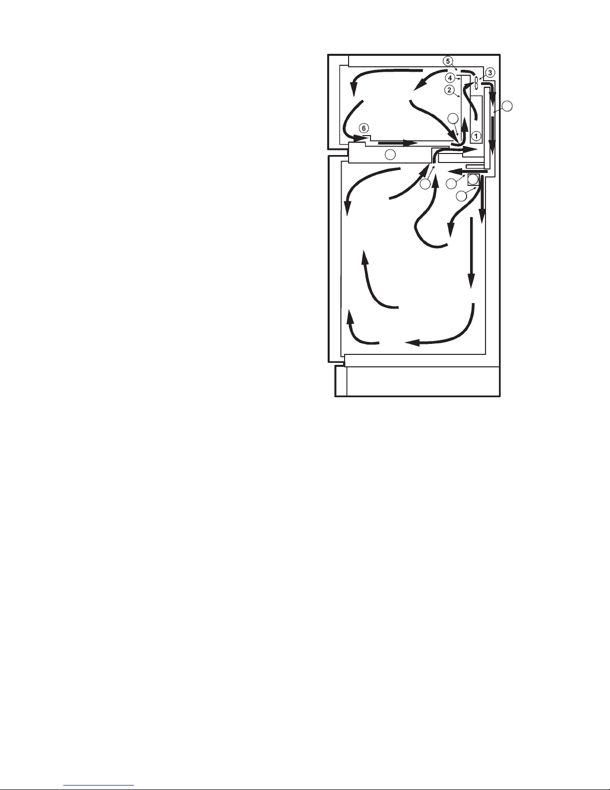
AIR CIRCULATION
The evaporator fan circulates air inside the refrigerator and freezer sections. (
Fig. 24)
air circulates inside the freezer compartment, and
returns to the evaporator from slots in the front and
rear of the freezer floor. The return air travels between the floor and the liner, where it joins other
return air at the back, flowing beneath the evaporator cover and up through the evaporator coil.
Cold air is also sent to the refrigerator section
through the air duct at the rear of the freezer section. The cold air enters the refrigerator section
through a diffuser. Part of the air is forced forward
where is passes through the front part of the compartment and the shelves in the door. Part of the
cold air is directed down the back of the compartment to cool the lower portion of the refrigerator
section. The warmed air is then returned to the
freezer section through two air return ducts.
Figure 24 Key:
1 - Evaporator 7 - Separator
2 - Evaporator Cover 8 - Air Duct
3 - Evaporator Fan 9 - Diffuser
4 - Fan Scroll 10 - Cold Air Discharge
5 - Cold Air Discharge 11 - Cold Air Discharge
6 - Return Air Louvers 12 - Air Return (2)
Most of the
7
Fig. 24
8
6
9
10
12
11
OLD DESIGN 12 & 14 cu. ft. Top-Mount
18
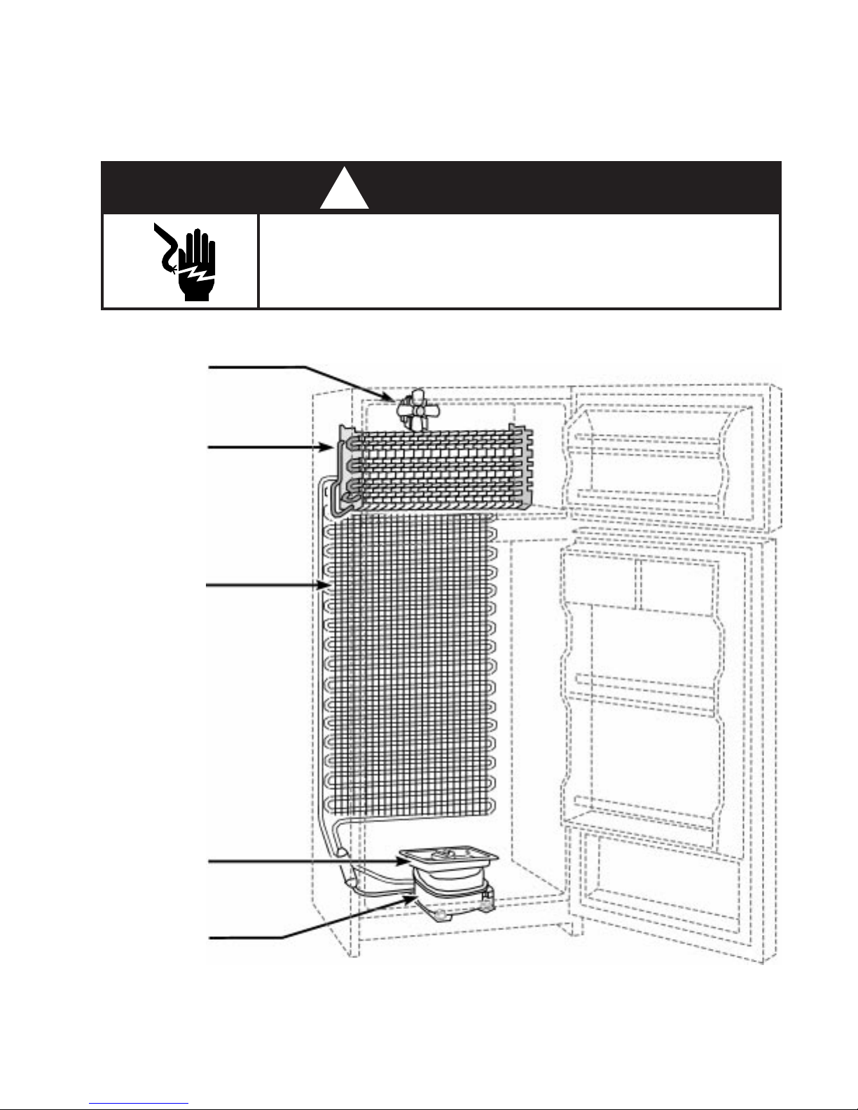
COMPONENT ACCESS
Component Location
Disconnect the electrical power before servicing any components.
EVAPORATOR
FAN
EVAPORATOR
! WARNING
ELECTRIC SHOCK HAZARD
Failure to do so can result in death or electrical shock.
CONDENSER
COLLECTOR
PAN
COMPRESSOR
Fig. 25
OLD DESIGN 12 & 14 cu. ft. Top-Mount
19
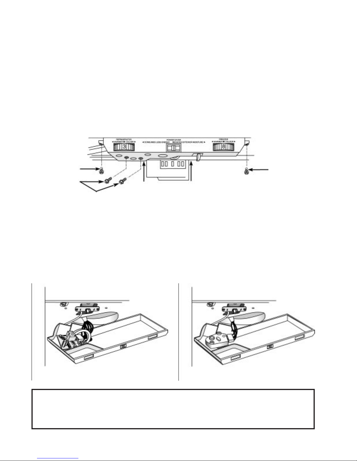
Servicing the Defrost Timer and Thermostat
Removing the Control Box
The Control box is attached to the bottom of the divider wall separating the freezer and refrigerator
compartments. The control box contains the defrost timer and the operating thermostat.
1. Remove the two (2) mounting screws securing the front of the control box to the bottom of
the separator.
2. Pull the control box forward to release the two (2) tabs securing the back of the control box
to the bottom of the separator.
3. The control box can now be dropped down to allow access to the defrost timer and the
thermostat.
COVER
MOUNTING
SCREW
DEFROST TIMER
MOUNTING
SCREWS
(Fig. 26)
TAB
AT
REAR OF
CONTROL BOX
DEFROST TIMER
MOUNTING
SCREWS
TAB
AT
REAR OF
CONTROL BOX
Fig. 26
Servicing the Defrost Timer
There are two different types of defrost timers, depending on the model being serviced. Figure 27
shows an Electronic Defrost Control. Figure 28 shows a typical Electromechanical Defrost Timer.
Both types of defrost timers are secured in the control box with the same mounting screws as
shown in Figure 28.
Fig. 27
Fig. 28
NOTE: Units with Adaptive Defrost Control will have the ADC printed circuit board mounted in
the same location as the Electromechanical Defrost Timer pictured above. Two
additional wires (Brown and White) are provided and connect to terminals 5 and 6 of
the ADC.
OLD DESIGN 12 & 14 cu. ft. Top-Mount
20
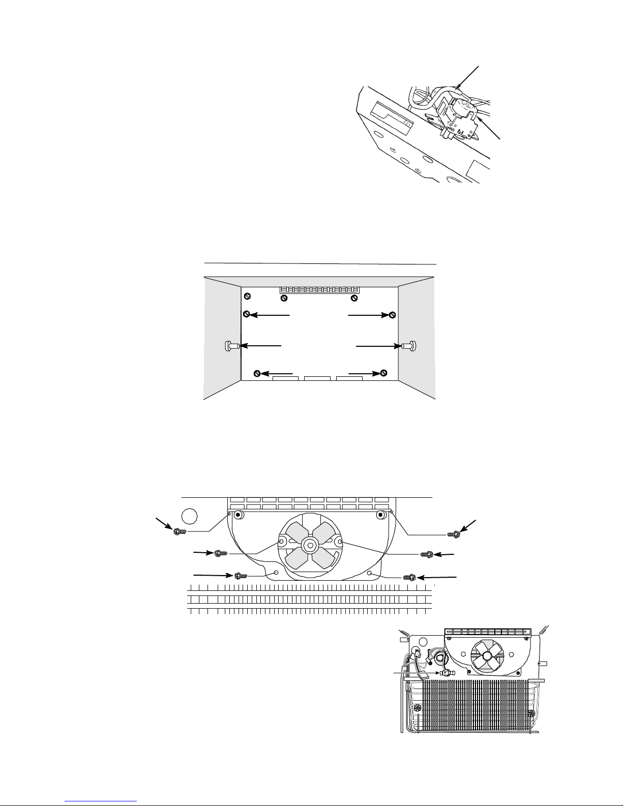
Servicing the Thermostat
SENSOR TUBE
The thermostat is mounted in the cross rail area
by two (2) mounting screws.
When removing the thermostat the sensing tube
will also have to be removed. The sensing tube is
THERMOSTAT
routed back to the deffuser. To access the sensing
tube, remove the two (2) screws securing the deffuser cover.
(Fig. 29)
Fig. 29
Servicing the Evaporator Fan
Access to the Evaporator Fan is possible once the Evaporator Cover has been removed.
1. Remove the evaporator mounting screws and remove the evaporator cover.
MOUNTING
SCREWS
SHELF STUDS
MOUNTING
SCREWS
(Fig. 30)
Fig. 30
2. Remove the four (4) screws securing the fan shroud to the back wall of the freezer section
and lift the shroud off.
(Fig. 31)
3. Remove the two (2) screws securing the fan motor mounting bracket to the back wall of the
freezer section and lift the fan motor assembly from its location.
(Fig. 31)
4. Disconnect the wiring harness connector from the fan motor terminals.
SHROUD
MOUNTING
SCREW
SHROUD
MOUNTING
SCREW
FAN MOUNTING SCREW
SHROUD MOUNTING
SCREW
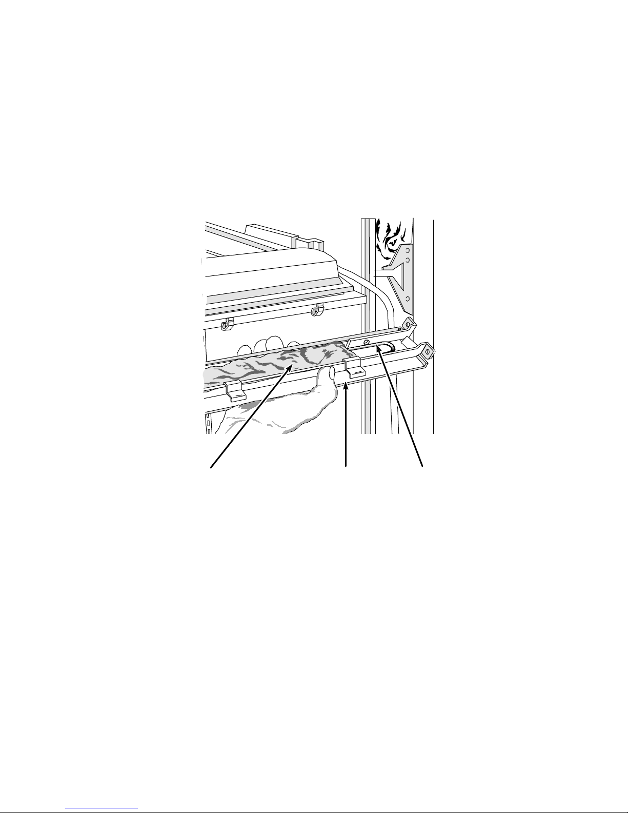
Servicing the Bi-Metal
The Bi-Metal
on the back wall of the freezer section.
1. Gently pry the bi-metal retaining clip up
2. Disconnect the bi-metal wire connector from
OLD DESIGN 12 & 14 cu. ft. Top-Mount
(Fig. 32)
is attached to the heat shield
and slide the bi-metal out from under the clip.
the wiring harness plug.
FAN MOUNTING SCREW
SHROUD MOUNTING
SCREW
Fig. 31
BIMETAL
Fig. 32
21
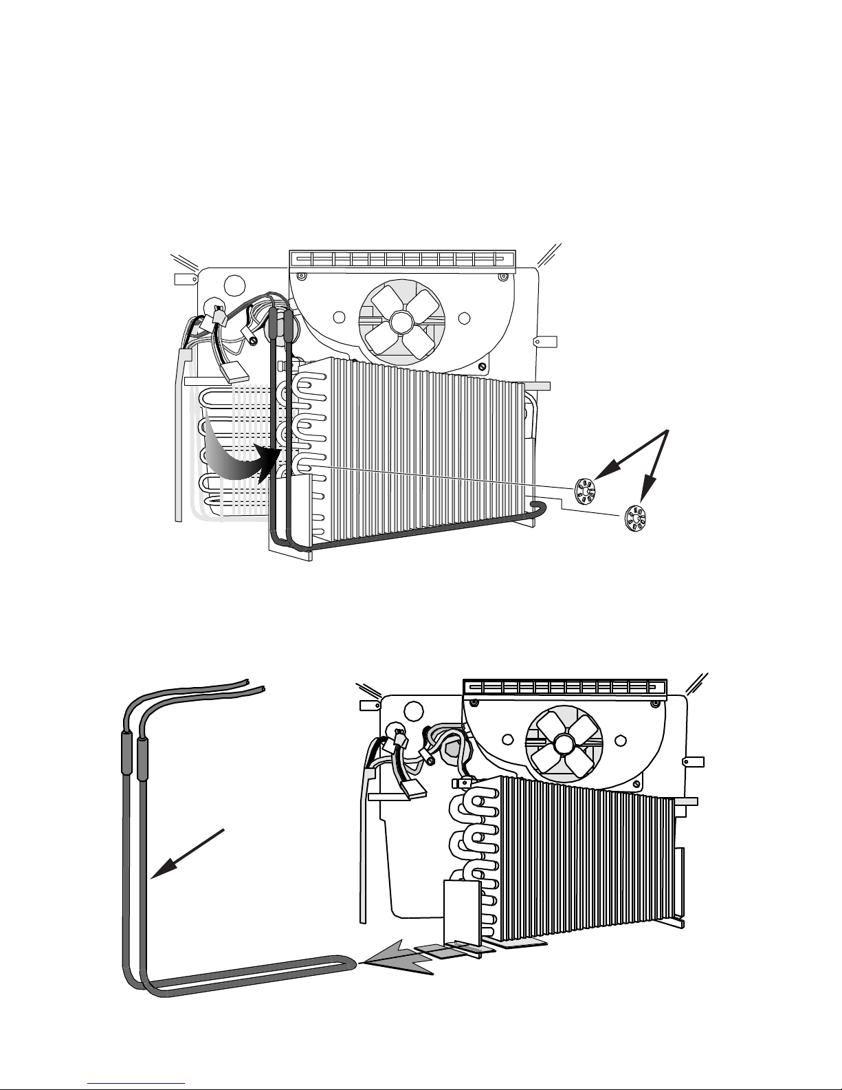
Servicing the Defrost Heater
The defrost heater is located on the left side and bottom of the evaporator and is held in place by
two slotted retainers at the bottom of the evaporator.
1. Release the evaporator from its position by first pulling the two plastic retaining clips from
the bosses that secure the evaporator to the heat shield.
2. Gently pull the left end of the evaporator away from the heat shield. Be careful not to kink
the evaporator outlet tubing.
(Fig. 33)
PLASTIC
RETAINING
CLIPS
Fig. 33
3. Gently slide the defrost heater by pulling it to the left and out of the retaining slots on the
evaporator.
(Fig. 34)
4. Disconnect the defrost heater wire connector from the wiring harness plug.
DEFROST
HEATER
OLD DESIGN 12 & 14 cu. ft. Top-Mount
Fig. 34
22
Servicing the Mullion Heater
The electrical mullion rail heater can be replaced and can be accessed by removing the mullion rail
cover.
1. Remove the doors following the procedures described in earlier in this section.
2. Remove the two screws on the opposite side of the mullion from the hinges.
3. Slide one end of the mullion rail cover to the left or right under the cabinet flange enough to
free the other end of the cover.
4. Slide the mullion in the opposite direction and remove it from the mullion rail.
5. Disconnect the mullion heater wire connector from the wiring harness plug.
(Fig. 35)
INSULATION
MULLION
RAIL COVER
Fig. 35
MULLION
HEATER
ELEMENT
OLD DESIGN 12 & 14 cu. ft. Top-Mount
23
WIRING DIAGRAM
(Early Mullion & Stile Heater Design)
STRIP CIRCUITS
(Early Mullion & Stile Heater Design)
COOLING CYCLE
Compressor Circuit (at instant of start)
Compressor Circuit (running)
OLD DESIGN 12 & 14 cu. ft. Top-Mount
24
 Loading...