

Page 1
Installation Instructions
F
or quick reference, please record the following:
Model Number
Serial Number
Model/Serial plate located on the oven behind the door.
Date of Purchase
Dealer Phone No.
Under-the-Cabinet
Microwave Oven
Part No. 8204864/3828W5U0311
Quick Reference
Table of Contents:
Pages
Before you start
Product dimensions
Location
Electrical requirements
Installation steps
2
2
2
3
3
www.whirlpool.com
IMPORTANT:
Installer: Leave Installation
Instructions with the homeowner.
Homeowner: Keep Installation
Instructions for future reference.
Read and save these instructions for
local electrical inspector’s use.
IMPORTANT:
Read and save these instructions.
Page 2
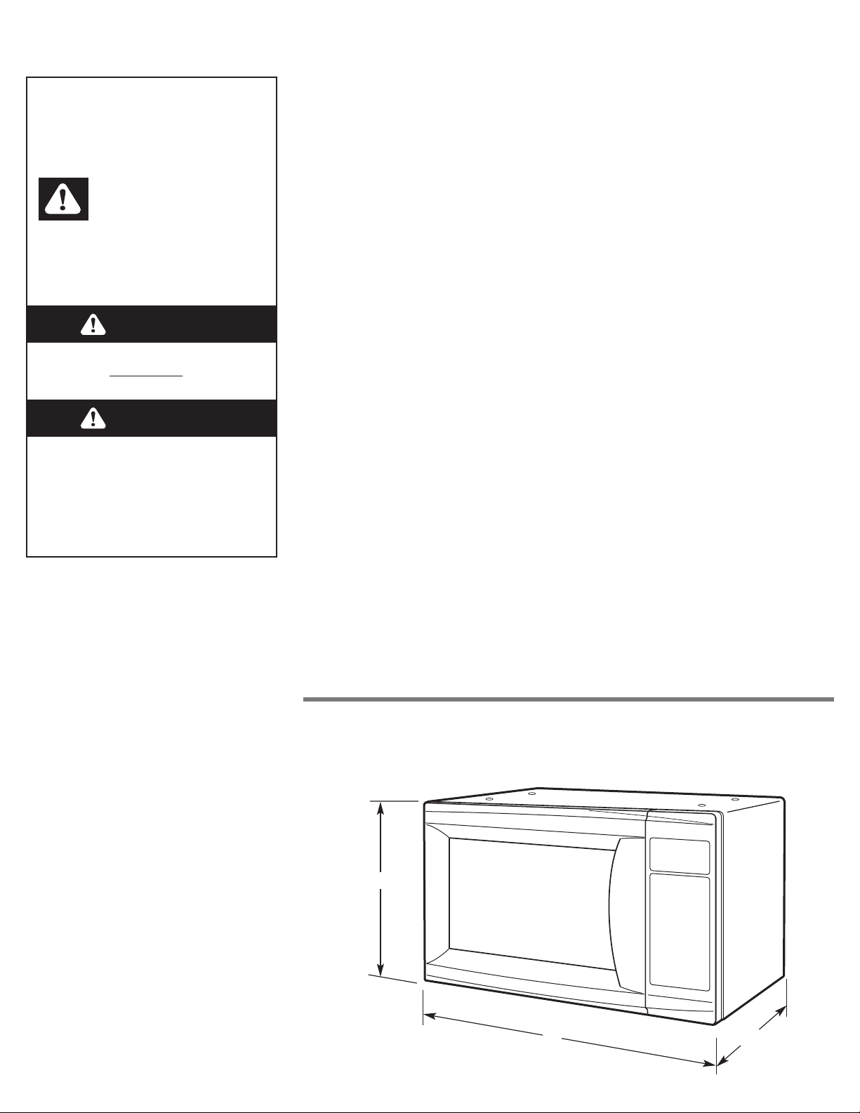
Product dimensions
11 "
18"
12-3/8"
Before you start... Tools recommended
for installation:
Parts included for
Installation:
You need to:
✓ observe all governing codes and
ordinances.
✓ install microwave oven as specified in
these instructions or as specified on
upper cabinet template.
✓ have everything you need to properly
install microwave oven.
✓ check the microwave oven for damage.
If any damage is evident, do not
operate the microwave oven until it is
checked by an authorized service
technician.
✓ place a portion of carton or other
heavy material between the microwave
oven and the floor or countertop. Do
not use a plastic cover.
✓ remove shipping materials and parts
from inside the microwave oven.
Locate templates and set them aside to
be used later.
✓ make sure the microwave oven will be
mounted against and supported by
upper cabinet or other horizontal
structure.
✓ support for an additional weight of
90 lbs (41 kg), which includes
microwave oven and items placed in
the oven.
Assemble the required tools and parts
before starting installation. Read and
follow the instructions provided with any
tools listed here.
• Phillips screwdriver
• electric drill
• 1/2” drill bit
• 1/2” wood bit or metal hole cutter
(if metal cabinet is used)
• protective covering, such as a blanket
for microwave and countertop (you may
also use carton for protection)
• scissors
• pencil
• measuring tape
• masking tape or similar
• center punch
• hammer
the installation hardware items are in
a small bag packed below the oven.
• 4 – 1-3/8" mounting screws
• 4 – 2-3/8" mounting screws
• 2 – mounting holders
• 8 – 1/4" spacers
• template
2
Location
NOTE:This microwave oven is intended
for installation over a countertop. Do not
install this microwave oven above any
heat source such as a range or cooktop.
Check the cabinet:
The cabinet must be a minimum of 12"
(30.5 cm) deep. The bottom shelf of your
cabinet must be at least 3/16" (4.8 mm)
thick and strong enough to support an
additional weight of 90 lbs (41 kg).
NOTE:This weight is in addition to the
normal contents of the cabinet, as well
as any other objects hung from the
bottom of the cabinet.
To provide for adequate ventilation, do
not install the microwave closer than
2-9/16" (6.5 cm) to a side wall.
Your safety and the safety of
others are very important.
We have provided many important safety
messages in this manual and on your
appliance.Always read and obey all
safety messages.
This is the safety alert symbol.
This symbol alerts you to
potential hazards that can kill
or hurt you and others.
All safety messages will follow the safety
alert symbol and either the word
“DANGER”or “WARNING.”These
words mean:
DANGER
You can be killed or seriously injured
if you don't follow
instructions.
immediately
WARNING
You can be killed or seriously injured
if you don't follow instructions.
All safety messages will tell you what the
potential hazard is, tell you how to
reduce the chance of injury,and tell you
what can happen if the instructions are
not followed.
Page 3
3
Electrical requirements
IMPORTANT: Observe all governing
codes and ordinances.
It is the customer’s responsibility:
To assure that the electrical installation is
adequate and in conformance with
National Electrical Code, ANSI/NFPA 70
— latest edition*, and all local codes and
ordinances.
You must have:
✓ 120-volt, 60Hz, AC-only, 15 or 20 amp,
fused (or circuit breaker) grounded
electrical supply.
✓ outlet located as close as possible to
the microwave oven.
We recommend:
✓ a time-delay fuse or circuit breaker.
✓ a separate circuit serving this
appliance only.
If codes permit and a separate ground
wire is used, it is recommended that a
qualified electrician determine that the
ground path is adequate.
Recommended ground
method
For your personal safety, this appliance
must be grounded. This appliance is
equipped with a power supply cord
having a 3 prong ground plug. To
minimize possible shock hazard, the cord
must be plugged into a mating 3 prong
ground-type wall outlet, grounded in
accordance with the National Electrical
Code, ANSI/NFPA 70 — latest edition*,
and all local codes and ordinances.
Copies of the standards listed may be obtained
from:
* National Fire Protection Association
One Batterymarch Park
Quincy, Massachusetts 02269
Installation steps
1. Remove contents from the bottom
shelf of your cabinet.
2. Location of template: Select the
easiest position to work from, either on
the inside bottom of the cabinet or the
underside of the cabinet to locate the
template.
When putting the template in place, make
sure the front of the cabinet is directly
above the front of the microwave oven
cabinet, not the microwave oven door.
Go to “Template instructions” on next
page.
3. Once the template is in place and
taped down, use a center punch, or a nail,
to mark the position of the 4 holes, as
shown on the template. Remove the
template.
4. Drill 4 holes through the cabinet
at the marked locations, using a 1/2"
(12.7 mm) drill bit.
5. Remove the four plugs from top of
microwave oven cabinet. Be sure to save
these plugs. If the microwave oven is
used later as a countertop model, these
plugs will need to be replaced.
6. If the cabinet has a front frame
extending below cabinet bottom go to
Step 6a.
If the cabinet does not have a front frame
extending below the cabinet bottom go to
Step 6b.
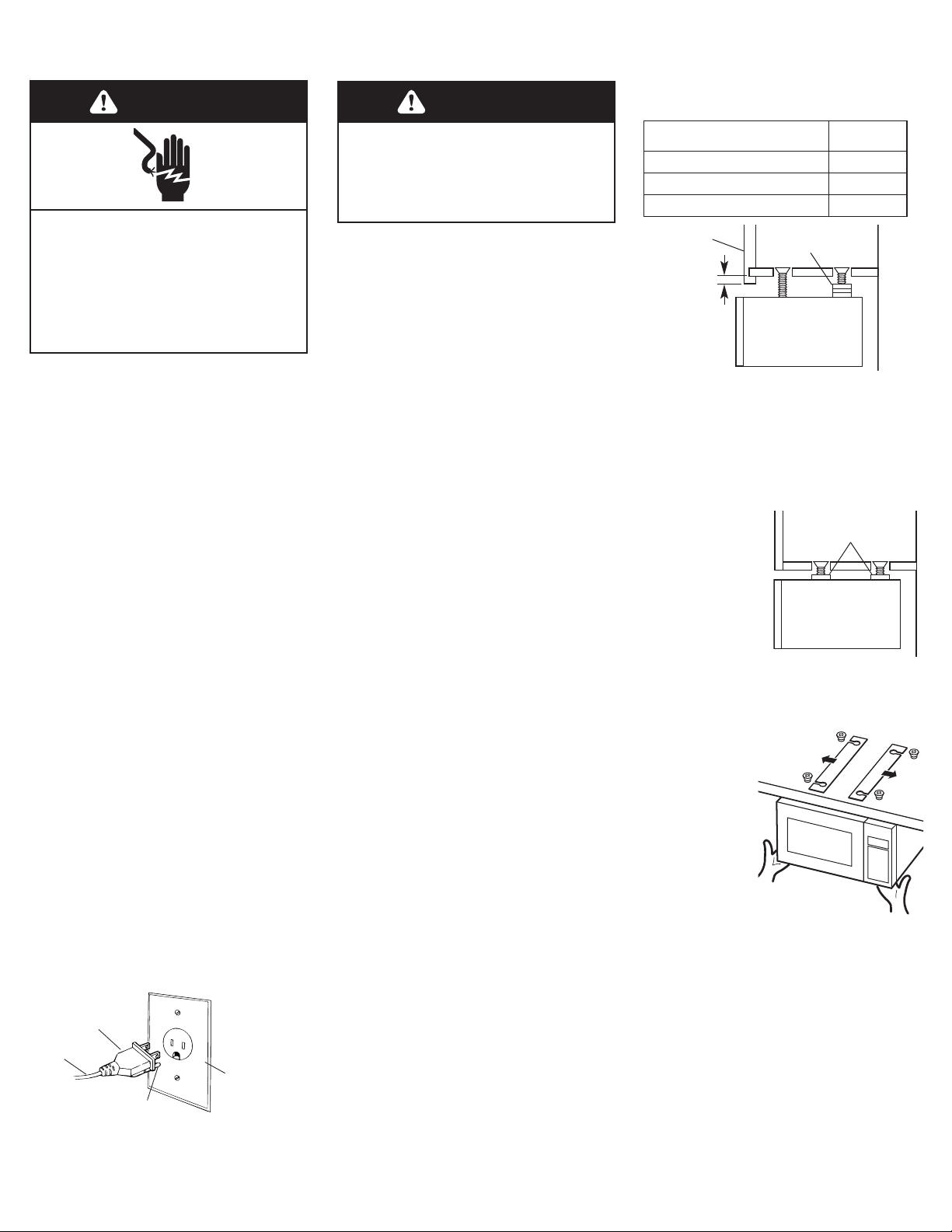
6a. If the cabinet has a front frame
extending below cabinet:
Measure the distance from the bottom of
the cabinet to the bottom of the front
frame, to determine which of the
mounting screws provided, (short or
long) and how many of the spacers
provided, will need to be used to install
the oven properly.
3 prong
ground plug
3 prong
ground-type
wall receptacle
ground prong
power
supply cord
Slide the correct number of spacers on
the back mounting screws only.
Insert each screw into a threaded hole in
the top of the oven. Turn each screw three
or four times to start the screw into the
threaded hole
6b. If the cabinet does not have a
front frame extending below the cabinet
bottom:
Slide one spacer
over each of the
four mounting
screws or, for a
smaller gap, use
1/4” I.D. flat
washers available
from hardware
store.
Insert each screw into a threaded hole in
the top of the oven. Turn each screw three
or four times to start the screw into the
threaded hole.
7. Lift the
microwave oven
so the mounting
screws enter
into the four
holes in the
bottom of the
cabinet. Slide
the mounting
holders onto the
necks of the mounting screws.
8. Slowly tighten the four screws
evenly until the oven is completely secure
and level.
9. Plug power supply cord into a
grounded 3 prong outlet.
To get the most efficient use from
your under-the-cabinet microwave
oven, read your Use and Care
guide.
front frame
of cabinet
spacers
A
supplied spacers or
1/4" I.D. flat washers
Distance “A”
Number of
spacers
0 – 1/2" (0 – 12.7 mm) 0 – 2
1/2" – 3/4" (12.7 mm – 19.1 mm) 2 – 3
3/4" – 1" (19.1 mm – 25.4 mm) 3 – 4
WARNING
Electrical Shock Hazard
Plug into a grounded 3 prong outlet.
Do not remove ground prong.
Do not use an adapter.
Do not use an extension cord.
Failure to follow these instructions can
result in death, fire, or electrical shock.
WARNING
ExcessiveWeight Hazard
Use two or more people to move and
install microwave oven.
Failure to do so can result in back or
other injury.
Page 4
Te mplate instructions
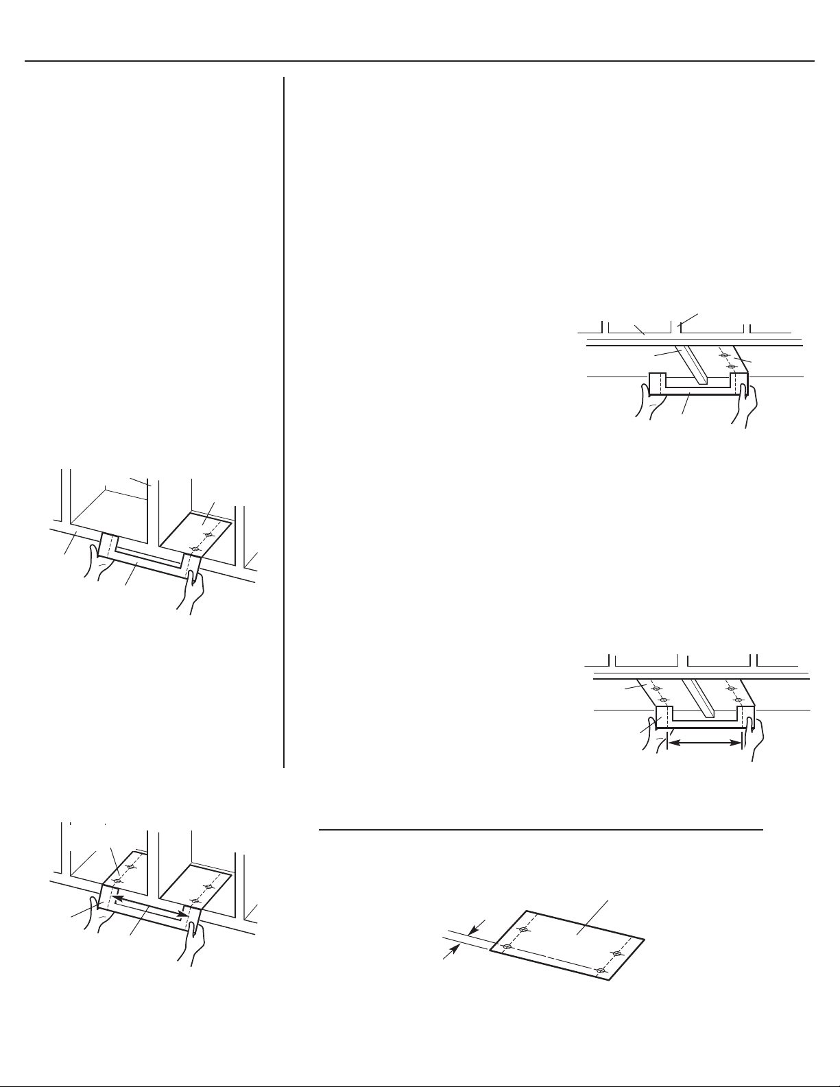
Drilling from inside the cabinet
If you cannot drill from inside the
cabinet, see "Drilling from under the
cabinet" section.
If the cabinet does not have a partition or
you are not installing under two
adjoining cabinets:
Place template inside the cabinet so
that the front line of the Template A will
be aligned with the front edge of the
cabinet. If necessary, cut some areas of
the template in order to make it fit
properly within cabinet.
See NOTE at bottom of page.
If the cabinet has a partition or you are
installing under two adjoining cabinets:
1. Cut Template B from template A along
the dotted line.
2. Cut Template A into two pieces to fit
each side of the partition.
3. Position one piece of Template A inside
cabinet making sure the front line is
aligned with the front edge of the
cabinet. Tape in place.
4. Position Template B in front of the
cabinet so that the hole centerline is
aligned with the hole centerline of the
Template A piece positioned in Step 3
above.
5. Position the other piece of Template A
inside the adjacent cabinet opening so
that the hole centerline aligns with the
hole centerline on Template B. Tape in
place. If you have followed the
instructions properly, the distance
between the right and left hole
centerlines will be 12-7/8" (32.7 cm).
See NOTE to right.
piece of
Template A
front frame
of cabinet
partition
Te mplate B
other piece of
Template A
Te mplate B
12-7/8"
(32.7 cm)
Drilling from under the cabinet
If the cabinet does not have a front frame
exending below the cabinet, there is no
partition, or you are not installing under
two adjoining cabinets:
Tape Template A to the underside of
cabinet so the front line of template
will be aligned with the front edge of
the cabinet. If necessary, cut some
areas of the template in order to make
it fit properly on the underside of
cabinet.
See NOTE at bottom of page.
If cabinet has only a front frame
extending below the cabinet bottom and
no partition:
Measure the thickness of the frame.
Fold template along guide line that
matches the frame thickness. Place the
folded edge of template against the
back side of front frame on the
underside of the cabinet. Tape in place.
See NOTE at bottom of page.
Part No. 8204864/3828W5U0311
© 2004 Whirlpool Corporation.
Printed in China
2/2004
If the cabinet has a partition, you are
installing under two adjoining cabinets,
or there is a side frame as shown:
1. Cut Template B from template A
along the dotted line.
2. Cut Template A into two pieces to fit
each side of the partition or adjoining
cabinets.
3. Position one piece of Template A
under cabinet making sure the front
line is positioned against the back
side of front frame on the underside
of the cabinet. Tape in place.
4. Position Template B toward the rear
of the cabinet so that the hole
centerline is aligned with the hole
centerline of the Template A piece
positioned in Step 3 above.
5. Position the other piece of Template A
under the adjacent cabinet opening
so that the hole centerline aligns with
the hole centerline on Template B.
Tape in place. If you have followed
the instructions properly, the distance
between the right and left hole
centerlines will be 12-7/8" (32.7 cm).
See NOTE below.
piece of
Template A
partition or
adjoining cabinets
front frame
of cabinet
side frame
Te mplate B
other piece
of Template A
Te mplate B
12-7/8" (32.7 cm)
NOTE: For any of the template instructions used, when Template A is properly
installed, the distance from the front edge of the cabinet with cabinet door(s)
open to the centerlines of the front holes will be 2-1/16" (5.2 cm).
Return to Step 3 of “Installation steps.”
2-1/16"
(5.2 cm)
Template A
 Loading...