


R-102
CONSUMER CARE TECHNICAL
EDUCATION GROUP PRESENTS
2003 69˝ HIGH COUNTER-DEPTH SIDE-BY-SIDE REFRIGERATOR
Model GC1SHAXM
JOB AID
Part No. 8178551

FORWARD
This Whirlpool Job Aid, “2003 69˝ High Counter-Depth Side-By-Side Refrigerator” (Part No. 8178551), provides the technician with information on the installation, operation, and service of the 2003 69˝ High Counter-Depth Side-By-Side Refrigerator. For specific information on the model being serviced, refer to the “Use and Care Guide,” or “Tech Sheet” provided with the refrigerator.
The Wiring Diagram and Strip Circuits used in this Job Aid are typical and should be used for training purposes only. Always use the Wiring Diagram supplied with the product when servicing the unit.
GOALS AND OBJECTIVES
The goal of this JobAid is to provide information that will enable the service technician to properly diagnose malfunctions and repair the 2003 69˝ High Counter-Depth Side-By-Side Refrigerator.
The objectives of this Job Aid are to:
•Understand and follow proper safety precautions.
•Successfully troubleshoot and diagnose malfunctions.
•Successfully perform necessary repairs.
•Successfully return the refrigerator to its proper operational status.
WHIRLPOOLCORPORATION assumes no responsibility for any repairs made on our products by anyone other than Authorized Service Technicians.
Copyright © 2006, Whirlpool Corporation, Benton Harbor, MI 49022
- ii -
TABLE OF CONTENTS
|
Page |
GENERAL .............................................................................................................................. |
1-1 |
Refrigerator Safety ............................................................................................................. |
1-1 |
Model & Serial Number Designations................................................................................ |
1-2 |
Model & Serial Number Label And Tech Sheet Locations.................................................. |
1-3 |
INSTALLATION INFORMATION ............................................................................................ |
2-1 |
Cutout Dimensions............................................................................................................. |
2-1 |
Door Removal.................................................................................................................... |
2-2 |
Water Hookup .................................................................................................................... |
2-6 |
THEORY OF OPERATION ..................................................................................................... |
3-1 |
Overview............................................................................................................................ |
3-1 |
User Interface .................................................................................................................... |
3-2 |
Electronic Control Board.................................................................................................... |
3-4 |
Thermistors........................................................................................................................ |
3-4 |
Defrost Operation............................................................................................................... |
3-5 |
Fan Operation And Delay................................................................................................... |
3-6 |
In-Door Ice ......................................................................................................................... |
3-7 |
COMPONENT ACCESS ........................................................................................................ |
4-1 |
Component Locations........................................................................................................ |
4-1 |
Removing A Refrigerator Or Freezer Light Bulb ................................................................ |
4-2 |
Removing The Defrost Bimetal .......................................................................................... |
4-3 |
Removing The Refrigerator Thermistor Housing ............................................................... |
4-4 |
Removing The Water & Ice Dispenser Board Interface ..................................................... |
4-5 |
Removing The Evaporator Tray ......................................................................................... |
4-7 |
Removing The Control Board............................................................................................. |
4-8 |
Removing The Water Valves.............................................................................................. |
4-9 |
Removing The Condenser Fan Motor.............................................................................. |
4-10 |
Removing The Compressor Terminal Box, |
|
The Relay & Overload And Run Capacitor.................................................................... |
4-11 |
- iii -
COMPONENT TESTING ........................................................................................................ |
5-1 |
Component Testing Chart .................................................................................................. |
5-1 |
DIAGNOSTICS & TROUBLESHOOTING ............................................................................. |
6-1 |
User Interface Failure Feedback........................................................................................ |
6-3 |
Troubleshooting Chart........................................................................................................ |
6-5 |
Electronic Control Board Pin Locations ............................................................................. |
6-8 |
User Interface Board Pin Locations ................................................................................... |
6-9 |
Thermistor Resistance/Temperature Chart........................................................................ |
6-9 |
WIRING DIAGRAM & STRIP CIRCUITS ............................................................................... |
7-1 |
Wiring Diagram .................................................................................................................. |
7-1 |
Strip Circuits....................................................................................................................... |
7-2 |
TECH TIPS ............................................................................................................................. |
8-1 |
Removing The Original Gasket.......................................................................................... |
8-1 |
- iv -

GENERAL
REFRIGERATOR SAFETY
Your safety and the safety of others are very important.
We have provided many important safety messages in this manual and on your appliance. Always read and obey all safety messages.
This is the safety alert symbol.
This symbol alerts you to potential hazards that can kill or hurt you and others.
All safety messages will follow the safety alert symbol and either the word “DANGER” or “WARNING.” These words mean:
 DANGER
 WARNING
You can be killed or seriously injured if you don’t immediately follow instructions.
You can be killed or seriously injured if you don’t follow instructions.
Allsafetymessageswilltellyouwhatthepotentialhazardis,tellyouhowtoreducethechance of injury, and tell you what can happen if the instructions are not followed.
1-1

MODEL & SERIAL NUMBER DESIGNATIONS
MODEL NUMBER
MODEL NUMBER |
G |
|
C |
1 |
S H |
A |
|
X |
|
M |
|
Q |
|
0 0 |
|
|
|
|
|
||||||||||
|
|
|
|
|
|
|
|
|
|
|
|
|
|
|
PRODUCT GROUP |
|
|
|
|
|
|
|
|
|
|
|
|
|
|
G = Whirlpool Gold |
|
|
|
|
|
|
|
|
|
|
|
|
|
|
PRODUCT IDENTIFICATION |
|
|
|
|
|
|
|
|
|
|
|
|
|
|
C = Counter Depth (24˝ Deep) |
|
|
|
|
|
|
|
|
|
|
|
|
|
|
CAPACITY / CUBIC FOOT SIZE |
|
|
|
|
|
|
|
|
|
|
|
|
|
|
1 = 11 or 21 |
|
|
|
|
|
|
|
|
|
|
|
|
|
|
MODEL SERIES / SHELVES |
|
|
|
|
|
|
|
|
|
|
|
|
|
|
S = Shelf Variation |
|
|
|
|
|
|
|
|
|
|
|
|
|
|
MODEL FEATURES / PANS |
|
|
|
|
|
|
|
|
|
|
|
|
|
|
H = Crisper Variation |
|
|
|
|
|
|
|
|
|
|
|
|
|
|
MODEL FEATURE CODE |
|
|
|
|
|
|
|
|
|
|
|
|
|
|
A = IDI W/Grille Filter |
|
|
|
|
|
|
|
|
|
|
|
|
|
|
|
|
|
|
|
|
|
|
|
|
|
|
|
|
|
DOOR SWING |
|
|
|
|
|
|
|
|
|
|
|
|
|
|
X = SXS |
|
|
|
|
|
|
|
|
|
|
|
|
|
|
|
|
|
|
|
|
|
|
|
|
|
|
|
|
|
YEAR OF INTRODUCTION |
|
|
|
|
|
|
|
|
|
|
|
|
|
|
M = 2003 |
|
|
|
|
|
|
|
|
|
|
|
|
|
|
COLOR CODE |
|
|
|
|
|
|
|
|
|
|
|
|
|
|
Q = White |
|
|
|
|
|
|
|
|
|
|
|
|
|
|
B = Black |
|
|
|
|
|
|
|
|
|
|
|
|
|
|
S = Stainless |
|
|
|
|
|
|
|
|
|
|
|
|
|
|
|
|
|
|
|
|
|
|
|
|
|
|
|
|
|
ENERGY/POWER DESIGNATOR (NUMERIC)
0 = Original, 1 = 1st Change, 2 = 2nd Change, etc.
ENGINEERING CHANGE (NUMERIC)
0 = Basic Release
1 = First Revision
2 = Second Revision
SERIAL NUMBER
SERIAL NUMBER |
|
SA |
|
R |
|
48 |
|
10001 |
|
|
|
|
|
|
|||||
|
|
|
|
|
|
|
|
|
|
MANUFACTURING RESPONSIBILITY |
|
|
|
|
|
|
|
|
|
SA = Fort Smith, AR |
|
|
|
|
|
|
|
|
|
|
|
|
|
|
|
|
|
|
|
YEAR OF PRODUCTION |
|
|
|
|
|
|
|
|
|
R = 2004 |
|
|
|
|
|
|
|
|
|
|
|
|
|
|
|
|
|
|
|
WEEK OF PRODUCTION |
|
|
|
|
|
|
|
|
|
48th Week |
|
|
|
|
|
|
|
|
|
|
|
|
|
|
|
|
|
|
|
PRODUCT SEQUENCE NUMBER |
|
|
|
|
|
|
|
|
|
|
|
|
|
|
|
|
|
|
|
1-2
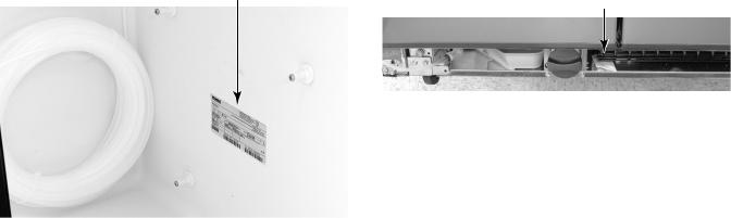
MODEL & SERIAL NUMBER LABEL
AND TECH SHEET LOCATIONS
The Model/Serial Number label and Tech Sheet locations are shown below.
Model & Serial Number Label Location
(On Lower Right Side Of Refrigerator Liner) Tech Sheet Location (Behind Grille)
1-3
— NOTES —
1-4
INSTALLATION INFORMATION
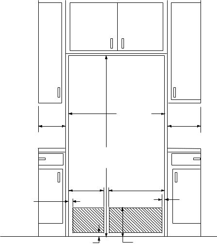
CUTOUT DIMENSIONS
36" (91.5 cm)
131/4" |
161/2" |
(34 cm) |
(42 cm) |
69" (175.0 cm)
|
121/2" |
201/4" |
|
2" |
(32 cm) |
(51.5 cm) |
2" |
|
|
||
(5.1 cm) |
|
|
(5.1cm) |
|
21/2" |
91/4" |
|
|
(6.4 cm) |
(23.5 cm) |
|
2-1
DOOR REMOVAL
TOOLS REQUIRED
1/2ʺ & 5/16ʺ Hex-Head Socket Wrenches Flat-Blade Screwdriver
#1 & #2 Phillips Screwdrivers
BEFORE YOU BEGIN
Turn the refrigerator control OFF. Unplug the refrigerator or disconnect power. Remove the food and any adjustable door or utility bins from the doors.
HANDLE REMOVAL (OPTIONAL)
1.Using a Phillips screwdriver, remove the screws located on the inside of each door handle. Pull the door handle straight out from the door (see Illustration 1). Save the screws for reattaching the handles.
2.Tomakethecabinetflush,useaflat-blade screwdriver, and remove the screws attaching the door handle posts to the refrigerator cabinet. Reverse the procedure to replace the handles.
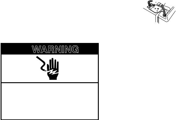
DOOR REMOVAL
 WARNING
Electrical Shock Hazard
Disconnect power before removing doors.
Failure to do so can result in death or electrical shock.
1.Unplug refrigerator or disconnect power.
2.Open both doors and remove the two screws from the base grille. Pull the base grille forward and remove it (see Illustration 2).
3.Close both doors and keep them closed until you are ready to lift them off the cabinet.
4.If you have a dispenser (ice or water), disconnect the water dispenser tubing, locatedbehindthebasegrilleonthefreezer door side (see Illustration 3). To do this, press the red outer ring against the face of the fitting, and pull the dispenser tubing free. NOTE: On some models, you will have to remove the tubing from a hose clip.
5.Removethetoplefthingescrewandcover as shown (see Illustration 4).
6.Disconnect the wiring plug as shown.

 2 1
2 1


1.Do not remove screw 1
2.Wiring plug
7.Remove the remaining left hinge screws and hinge (see Illustration 4).
8.Carefully lift the freezer door straight up and off the bottom hinge (see Illustration 5). The water dispenser tubing will remain attached to the freezer door, and will pull through the bottom left hinge. Make sure that you protect the dispenser tubing from damage when you set the door on the floor.
9.Remove the top right hinge cover and screws (see Illustration 6).
10.Lift the refrigerator door straight up and off the bottom hinge.
11.Disassemble the hinges as shown (see Illustration 7). Do not remove the screws.
2-2
4 Top Left Hinge |
|
5 Door Removal |
|
6 Top Right Hinge |
|
|
|
|
|
|
|
|
|
|
|
|
|
|
|
|
|
|
|
|
|
|
|
|
|
3Water Dispenser
Tubing Connection |
1 Handle Removal |
7 Bottom Hinge |
|
(Optional) |

 1
1
1. Do Not Remove Screws
2 Base Grille
1
1. Red Outer Ring
|
|
|
|
|
|
1. Screws |
1 |
|
|
|
|
|
|
|
|
|
|
|
Door Closing and Alignment |
|
|
||
8 |
Level |
9 |
Rear Leveling |
10 |
Door Alignment |
11 Front Leveling |
|
|
|
|
1 |
|
|
|
|
|
|
|
|
|
|
|
1 |
|
|
1. Rear roller leveling screw |
|
|
1. Front roller leveling screw |
||
2-3
DOOR AND HINGE REPLACEMENT
1.If removed, replace both bottom hinges and tighten the screws.
2.Carefullyfeedthedispensertubingthrough the bottom left hinge before replacing the freezer door on the hinge.
NOTE:Provideadditionalsupportforthedoors whilethetophingesarebeingreplaced.Donot depend on the door magnets to hold the doors in place while you are working.
3.Reconnect the water dispenser tubing by pushing the tubing into the fitting until it stops, and the black mark touches the face of the fitting (see Illustration 3). On some models, replace the tubing in the hose clip.
4.Align and replace the top left hinge (see Illustration 4) and tighten the screws.
5.Reconnect the wiring plug.

 2 1
2 1


1.Do not remove screw 1
2.Wiring plug
6.Replace the left hinge cover and screws.
7.Carefully lift the refrigerator door and set it on the bottom right hinge.
8.Align and replace the top right hinge (see Illustration 6).
9.Replace the hinge cover and screws.
10.Plug in refrigerator or reconnect power.
DOOR CLOSING AND ALIGNMENT
Door Closing
1.Move the refrigerator into its final position.
2.Place a level inside the refrigerator at the back of the top shelf (see Illustration 8).
3.Locatethelevelingscrewsbehindthebase grille of the refrigerator on either side.
4.Useahex-headsocketwrenchandadjust the rear roller leveling screws until the refrigerator is level. Turn the rear roller leveling screw to the right to raise that side of the refrigerator, or to the left to lower it (see Illustration 9). Make sure the refrigerator is level before proceeding.
Door Alignment
If the doors are uneven after leveling the refrigerator (see Illustration 10), perform the following steps.
1.Useahex-headsocketwrenchandadjust the front roller leveling screws until the doorsareeven.Turnthefrontrollerleveling screw to the right to raise that side of the refrigerator, or to the left to lower it (see Illustration 11).
NOTE: Open and close both the refrigerator and freezer doors after each adjustment to check the door alignment.
2.Open the doors and replace the base grille.Align the grille with the bottom of the cabinet and reattach with the screws.
NOTE: Be sure to refasten the Tech Sheet behind the base grille.
2-4

4 Top Left Hinge |
|
5 Door Removal |
|
6 Top Right Hinge |
|
|
|
|
|
|
|
|
|
|
|
|
|
|
|
|
|
|
|
|
|
|
|
|
|
3Water Dispenser
Tubing Connection |
1 Handle Removal |
7 Bottom Hinge |
|
(Optional) |

 1
1
1. Do Not Remove Screws
2 Base Grille
1
1. Red Outer Ring
|
|
|
|
|
|
1. Screws |
1 |
|
|
|
|
|
|
|
|
|
|
|
Door Closing and Alignment |
|
|
||
8 |
Level |
9 |
Rear Leveling |
10 |
Door Alignment |
11 Front Leveling |
|
|
|
|
1 |
|
|
|
|
|
|
|
|
|
|
|
1 |
|
|
1. Rear roller leveling screw |
|
|
1. Front roller leveling screw |
||
2-5

WATER HOOKUP
READ ALL DIRECTIONS COMPLETELY BEFORE YOU BEGIN.
IMPORTANT:
In order to prevent possible leakage resulting in property damage, be sure:
1.If you are operating the refrigerator before installing the water connection, turn the ice maker to the OFF position to prevent operation without water.
2.Use copper tubing.
3.Installtubingonlyinareaswheretemperatures will remain above freezing.
4.Allinstallationsmustbeinaccordancewith local plumbing code requirements.
5.See the “Installation Guide” for further information.
COLD WATER SUPPLY
Theicemakerwatervalvecontainsaflowwasher which is used as a water pressure regulator. The ice maker needs to be connected to a cold waterlinewithwaterpressurebetween30-120 psi. If you have questions about your water pressure, call a licensed, qualified plumber.
•If your refrigerator has a water filter cartridge, it may further reduce the water pressure when used in conjunction with a reverse osmosis system. Remove the water filter cartridge.
CONNECTING TO THE
REFRIGERATOR
1.Unplug refrigerator or disconnect power.
2.Remove the shipping tape from the gray, coiled water tubing on the rear of the refrigerator.
Style 1
1.Thread the provided nut onto the coupling on the end of the copper tubing.
Style 2
1.Thread the provided nut onto the water valve, as shown. First tighten the nut by hand, then tighten it with a wrench two more turns. Do not overtighten.
REVERSE OSMOSIS WATER SUPPLY
IMPORTANT: The pressure of the water supply coming out of a reverse osmosis system going to the water inlet valve of the refrigerator needs to be between 30-120 psi. If a reverse osmosis water filtration system is connected to your cold water supply, the water pressure to the reverse osmosis system needs to be a minimum of 40 - 60 psi. If the water system to the reverse osmosis water system is less than 40 - 60 psi:
•Check to see whether the sediment filter inthereverseosmosissystemisblocked. Replace the filter if necessary.
•Allow the storage tank on the reverse osmosis system to refill after heavy usage.
FINAL CHECKS
1.Turn water supply valve ON and check for leaks.Tightenanyconnectionsornutsthat leak (including connections at the valve).
2.Plug in refrigerator or reconnect power. NOTE: It may take up to 24 hours for the ice maker to begin producing ice.
2-6
THEORY OF OPERATION
OVERVIEW
The design of the 69ʺ tall counter-depth side- by-side refrigerator is similar to freestanding side-by-side refrigerators. There are, however, some very unique and important differences. This section will review the operation of this product and explain those unique differences.
The control system consists of an electronic user interface, located on the ice and water dispenser, an electronic control board, located at the left rear of the unit compartment, and thermistors, located in the refrigerator and freezer compartments. These controls communicate with each other, and manage virtually all of the functions of this refrigerator, with the exception of the in-door ice making feature.
3-1
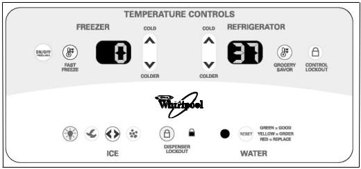
USER INTERFACE
The user interface allows the customer to adjust the temperatures, choose what kind of ice to be dispensed, and monitor the remaining water filter capacity. There are also lockout modes for the temperature controls and the ice and water dispenser. The temperatures are only displayed in Fahrenheit.
Each function is described below.
ON/OFF—Press the keypad for 2 seconds to turn the unit on and off.
When the unit is turned “off”:
•Only the central decimal point shows in both temperature displays.
•All functions are disabled.
•All lamps and lights are off.
When the unit is turned “on”:
•All functions are restored at power-up.
•Temperature settings before powerdown are remembered.
•Fast Freeze and/or Grocery Savor mode will be discontinued after powerup, if selected prior to power-down.
•The compressor will wait 7 minutes to start.
•The condenser fan will wait 1 minute to start after the compressor starts.
NOTE: At the first power-up, the control will start in the following DEFAULT operating mode:
•Unit is in the “On” state.
•Freezer temperature is set at 0ºF; Refrigerator temperature set at 37ºF.
•Self Diagnostic Mode enabled for 10 minutes.
•Ice in Cube mode.
•Dispenser light “off”.
•Time to defrost will be set at 30 hours of compressor run time, or 50 hours actual time.
FREEZER (Temperature Settings)—Adjust- ment ranges from –5°F to +5°F. Each time the COLD or COLDER keypad is pressed, the set temperature will raise or lower 1°F. The display shows only the set temperature.
REFRIGERATOR (Temperature Settings)— Adjustment ranges from 33°F to 41°F. Each time the COLD or COLDER keypad is pressed, the set temperature will raise or lower 1°F. The display shows only the set temperature.
FAST FREEZE—Pressing this keypad places the freezer section into continuous cool-down mode for 24 hours. The control will then return to the last freezer set temperature. While in this mode, the FAST FREEZE keypad is illuminated. Pressing the keypad a second time will terminate the FASTFREEZE mode.The refrigerator section temperature is not affected.
3-2
GROCERY SAVOR—Pressing this keypad places the refrigerator section into continuous cool-down mode for 6 hours. The temperature is regulated down to 33°F. After the 6 hour period, the control returns to the last refrigerator set temperature. Pressing the keypad a second time will terminate the GROCERY SAVOR mode. While in this mode, the GROCERY SAVOR keypad is illuminated.
CONTROLLOCKOUT—Pressing this keypad for 2 seconds disables all user interface control keypads relating to temperature regulation. While in this mode, the CONTROL LOCKOUT keypad is illuminated. If any other keypad is pressed, the LOCKOUT keypad indicator will blinktwice.PressingtheCONTROLLOCKOUT keypad again for 2 seconds, will enable all temperature control functions.
DISPENSER LIGHT—Pressing this keypad will turn the dispenser light on. Pressing the keypad again will turn off the light. When in the “off” mode, the light will illuminate when either dispenser paddle is pressed.
ICE MODE—This keypad toggles between cubed and crushed ice. In the cubed mode, the CUBED ICE indicator will illuminate. In the crushed mode, the CRUSHED ICE indicator will illuminate.
DISPENSER LOCKOUT—Pressing this keypad for 2 seconds disables the ice and water dispenser functions, and the related user interface control keypads. While in this mode the DISPENSER LOCKOUTkeypad is illuminated. If any other dispenser keypad or dispenser paddle is pressed, the LOCKOUT keypad indicator will blink twice. Pressing the DISPENSER LOCKOUT keypad again for 2 seconds will enable all of the dispenser functions.
WATER FILTER INDICATOR—The water filter indicator function is the same as on other Whirlpool refrigerators with filtered water systems. Pressing the RESET keypad for 2 seconds will reset the indicator back to green, and the counter will start over. The filter indicator can only be reset when the filter indicator light is “red,” no matter when the filter is changed. Maximum filter capacity is 400 gallons, or for a time period not to exceed 6 months.
3-3
 Loading...