

Whirlpool AGB 516/WP, AGB 524/WP, AGB 522/WP, AGB 525/WP, AGB 523/WP INSTRUCTION FOR USE
...
005_03
Instructions for installation,
use and maintenance
06/2007
ELECTRIC FRYER
AGB 597/WP · AGB 521/WP
AGB 515/WP · AGB 598/WP
AGB 523/WP · AGB 516/WP
AGB 522/WP · AGB 514/WP
AGB 524/WP · AGB 525/WP
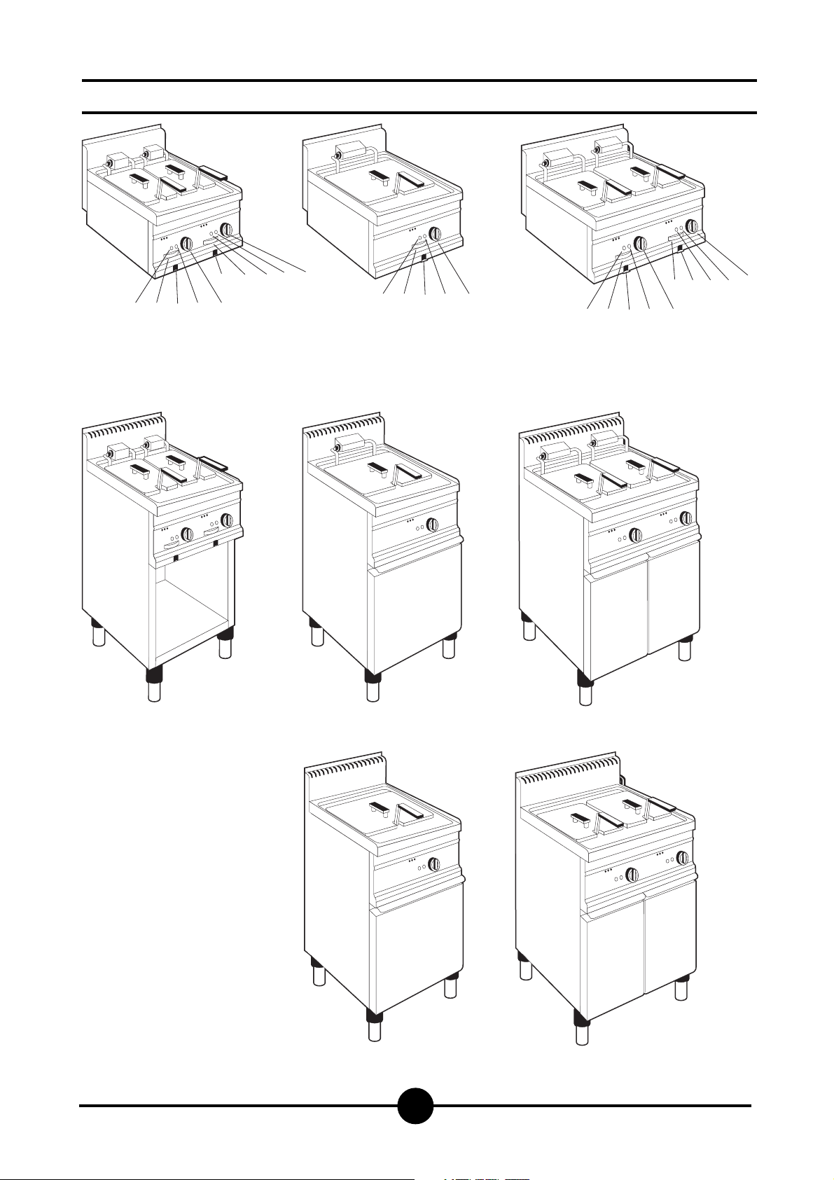
Models and dimensions page 3
Technical data 4
Installation instructions 5
Installation 5
Legal and technical requisites 5
Installation 5
Wiring 5
Unipotential 5
Start-up 5
Using the appliance 6
Ignition 6
Emptying the bath 6
Cleaning and taking care
of the appliance
page 6
What to do if not using the appliance for
a long time 6
What to do if something goes wrong 6
Maintenance 6
WEEE Directive 7
Wiring diagrams 8-12
Warning 13
INDEX
005-03 - Electric fryer
2
005-03 - Electric fryer
3
Dimensions
A
B
C
D
E
Main switch
Oil outlet drive
Pilot lamp (voltage)
Pilot lamp (resistences)
Oil outlet
400 x 650 x 270
Weight approx.
21 kg
AGB 514/WP
400 x 700 x 510
Weight approx.
21 kg
AGB 597/WP
400 x 650 x 270
Weight approx.
21 kg
AGB 515/WP
400 x 700 x 510
Weight approx.
21 kg
AGB 598/WP
600 x 650 x 270
Weight approx.
33 kg
AGB 516/WP
600 x 700 x 510
Weight approx.
33 kg
AGB 522/WP
400 x 700 x 875
Weight approx.
51 kg
AGB 521/WP
400 x 700 x 875
Weight approx.
51 kg
AGB 523/WP
600 x 700 x 875
Weight approx.
85 kg
AGB 524/WP
400 x 700 x 875
Weight approx.
53 kg
AGB 525/WP
800 x 700 x 875
Weight approx.
96 kg
CBEDA
EBCDA
CBEDA
CBEDA
BE CD A
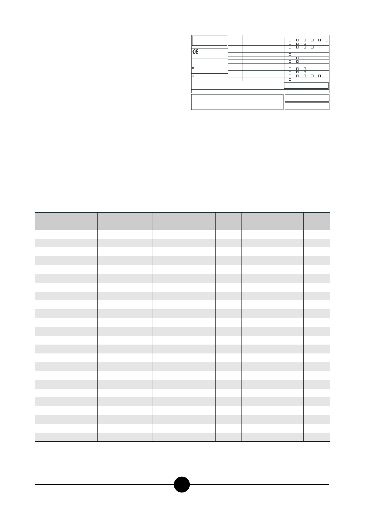
Technical data
The data plate is located on the front of the appliance and
contains all the data needed for connecting it up to the
mains electricity supply.
005-03 - Electric fryer
4
FRYER
CAT/KAT GAS/GAZ G30 G31 G20 G25
II2H3B/P P mbar 30 30 20 -
II2H3+ P mbar 30 37 20--
II2H3+ P mbar 28 37 20 -
TIPO/TYPE
MOD.
ART.
N.
N.
Qn kW
MOD.
V AC kW Hz
THE APPLIANCE MUST BE CONNECTED IN COMPLIANCE WITH THE LAWS IN FORCE
AND INSTALLED IN A WELL-VENTILATED ROOM. READ THE INSTRUCTION MANUALS
BEFORE INSTALLING AND USING THE APPLIANCE.
THE APPLIANCE MUST BE INSTALLED BY QUALIFIED PERSONNEL.
II2ELL3B/P P mbar 50 50 20 20
II2E+3+ P mbar 28 37 20 25
II2H3B/P P mbar 50 50 20 -
I2E P mbar - - 20 -
II2H3+ P mbar 28 37 20 -
I3B/P P mbar 30 30
m3/h
I3+ P mbar 28 37
Predisposto a gas: - Gas preset: - Prevu pour gaz:
Eingestelt für Gas: - Preparado para gas: -
--II2H3B/P P mbar 30 30
--
--
Geschuckt voor:
SE FI DK CZ SK SI
IT CH PT
ES IE GB GR
NL
25II2L3B/P P mbar 30 30
DE
FR BE
AT CH
LU
EE LV LT
EE LV LT
NO MT CY IS HU
CY
MADE IN ITALY
Model
AGB 597/WP
AGB 521/WP
AGB 515/WP
AGB 598/WP
AGB 523/WP
AGB 516/WP
AGB 522/WP
AGB 514/WP
AGB 524/WP
AGB 525/WP
Dim.: LxWxH
400 x 615 x 300
400 x 700 x 875
400 x 700 x 300
600 x 615 x 300
600 x 700 x 875
600 x 700 x 300
400 x 615 x 300
400 x 700 x 875
400 x 700 x 300
400 x 700 x 875
800 x 700 x 875
Voltage rating
230 V 3 AC or 400 V 3N AC
230 V 3 AC or 400 V 3N AC
230 V 3 AC or 400 V 3N AC
230 V 3 AC or 400 V 3N AC
230 V 3 AC or 400 V 3N AC
230 V 3 AC or 400 V 3N AC
230 V 3 AC or 400 V 3N AC
230 V 3 AC or 400 V 3N AC
230 V 3 AC or 400 V 3N AC
230 V 3 AC or 400 V 3N AC
230 V 3 AC or 400 V 3N AC
Power
7.5 kW
7.5 kW
7.5 kW
15.0 kW
15.0 kW
15.0 kW
6.2 kW
6.2 kW
6.2 kW
12.0 kW
24.0 kW
Lead wire / Section
4 x 2.5 mm
4 x 2.5 mm
4 x 2.5 mm
4 x 6 mm
4 x 6 mm
4 x 6 mm
4 x 2.5 mm
4 x 2.5 mm
4 x 2.5 mm
4 x 6 mm
4 x 10 mm
2
or 5 x 1.5 mm
2
or 5 x 1.5 mm
2
or 5 x 1.5 mm
2
or 5 x 2.5 mm
2
or 5 x 2.5 mm
2
or 5 x 2.5 mm
2
or 5 x 1.5 mm
2
or 5 x 1.5 mm
2
or 5 x 1.5 mm
2
or 5 x 2.5 mm
2
or 5 x 6 mm
2
2
2
2
2
2
2
2
2
2
2

Before beginning installation, remove all packaging from
the appliance. Some parts are protected with an adhesive
film which should be carefully removed.
Any remnants of glue should be thoroughly cleaned using
suitable substances such as benzine. Under no circumstances should abrasive substances be used.
Fit the legs to the appliance; the appliance must be levelled using a spirit level. Slight irregularities can be levelled
by adjusting the feet themselves.
With table models, make sure that the base chosen is capable of supporting the weight of the appliance. The main
switch or plug should be located in the vicinity of the appliance and easy of access. We recommend installing the
machine under a range hood so that all the fumes are removed as quickly as possible. If the appliance is to be installed near walls, dividing walls, kitchen equipment or decorative pannelling, these should be in non-inflammable
material or covered with non-inflammable material.
Make sure that all fire prevention standards and safety precautions are strictly adhered to.
Warning!
MODEL AGB 521/WP, AGB 522/WP, AGB 524/WP
If this model is going to be mounted on its own, it must
be fixed to the floor. Fixing accessories are included.
The appliance should be fitted following the indications given in the drawing below.
Warning!
With Top models, carefully measure the distance
between the appliance and the edge of the base (Fig. 2).
Legal and technical requisites
When installing the appliance, the following safety standards must be adhered to:
- Local accident prevention standards
- Current CEI standards.
Installation
Installation, start-up and maintenance should only be carried out by expert personnel. All work required to install
the appliance should be carried out in compliance with all
local standards and regulations. The manufacturers decline all responsibility where poor performance is due to incorrect installation in disregard of the above conditions.
Warning!
In compliance with international regulations, when
connecting the appliance to the mains power supply, a
device with a minimum aperture of 3 mm between contacts must be fitted upstream of the appliance, allowing omnipolar disconnection of the appliance from
the mains.
Wiring
When choosing the lead wire, make sure it has the following characteristics: it should be at least of the H07 RN-F
type and its section should be large enough for the appliance (see "Technical specifications and dimensions",
page 4).
Wire entry on top models is on the back wall, and underneath all other models. In both cases the terminal board is
at the front, behind the control panel.
Pass the wire through the core hitch and wire clamp, plug
the leads into their terminals on the board and secure
them.
The earth lead must be a little longerthan the others so
that it is the last lead to disconnect if the wire clamp
breaks.
Unipotential
The appliance must be connected up to a unipotential system. The connection screw is located on all top models at
the back on the right hand side, while in other models it is
located underneath the appliance on the right hand side.
It is labelled.
Warning!
The manufacturers cannot be held responsible for any
damage due to inadequate or incorrect installation.
Under such circumstances the guarantee will be considered null and void.
Start-up
Before using the appliance for the first time, thoroughly
clean out the oil bath (see paragraph entitled “Cleaning
and Taking Care of the Appliance”).
Check that the appliance is connected up properly and
start according to instructions overleaf.
INSTALLATION INSTRUCTIONS
005-03 - Electric fryer
5
1
RETRO
BACK
ARRIERE
RÜCKSEITE

Warning!
- Beware of inexpert handling!
- Old and dirty oil or frying fat can represent a real fire
hazard; make sure only new oil or frying fat are used
each time you start frying.
- The food you intend to fry should always be dry; wet
food causes the oil to foam and overflow.
- Frying excessively large quantities of food at a time
also causes the oil to foam; never exceed 1.5 kg.
- If the level of oil in the bath falls below the low level
mark stamped on it, the risk of fire will increase.
- Never leave the appliance on without any oil in it. The
lid delivered with the appliance should always be kept
within easy reach. In case of fire, it should be used to
douse the flames.
Ignition
Check that the oil drain release is closed. Fill the bath with
oil up to the level marked. Turn on the main switch
upstream of the appliance. Turn the knob from ‘0’ to any
temperature between 100°C and 195°C; the pilot lights will
come on. The green light means that the appliance is on,
while the orange one indicates that the resistances are on.
As soon as the required temperature is reached, the orange light will go off. To turn the appliance off, simply turn
the knob back to '0'.
Emptying the bath
First of all a suitable bowl for emptying the oil into should
be found. The bowl should be heat-resistant and designed
not to allow the oil to spill when the bath is being emptied,
since this could be very dangerous. A bowl with these requisites is available separately as an optinal extra from our
sales department. Fit the drainage pipe as shown in the
picture (2). Open the oil drain tap.
Important
With Top models, make sure you respect the distance
between the appliance and the edge of the base.
CLEANING AND TAKING CARE OF THE
MACHINE
Warning!
Never clean the appliance with jets of water, whether
direct or pressurised.
Allow the machine to cool down before cleaning
Before starting to clean the appliance, disconnect from
the mains. Using the hook provided (see drawing 3), you
can lift out the elements to make cleaning the appliance
easier and far more thorough. Lift the elements as far as
they will go. To lower them after cleaning, press the button
on the left hand side. All steel parts should be washed in
warm water, using a neutral detergent, then rinsed thoroughly to eliminate any residual detergent. Dry using a dry
cloth. Avoid using abrasive or corrosive detergents which
could damage the steel.
What to do if not using the appliance
for a long time
Thoroughly clean and dry the machine as described.
Disconnect the power supply.
What to do if something goes wrong
If anything goes wrong, immediately turn the appliance
off, then turn off the power supply at the switch located
upstream of the appliance, and call the aftersales department.
MAINTENANCE
All maintenance should be carried out by qualified personnel only. Before carrying out any maintenance work,
unplug the appliance or turn off the switch upstream of the
appliance.
USING THE APPLIANCE
005-03 - Electric fryer
6
2
3
MAX 120 mm

005-03 - Electric fryer
7
THE 2002/96/EC DIRECTIVE (WEEE):
information to users
This informational note is meant only for owners
of equipment marked with the symbol shown in
Fig. A on the adhesive label featuring the technical specifications applied on the actual pro-
duct (the label also giving the serial number).
This symbol indicates that the product is classified, according to the regulations in force, as an item of electrical
and electronic equipment and conforms to EU Directive
2002/96/EC (WEEE) meaning that, at the end of its service
life, it must be treated separately from domestic waste,
i.e. it must be handed in free of charge to a separate waste electrical and electronic equipment collection centre
or returned to the reseller when buying a new equivalent
item of equipment.
The user is responsible for delivering the unit at the end of
its life to the appropriate collection facilities. Failure to do
so shall result in the user being subject to the penalties
prescribed by the legislation in force on waste.
Suitable separated collection so that the unit no longer
used can be sent off for environmentally compatible recycling, treatment and disposal helps avoid possible negative effects on the environment and on health and facilitates the recycling of the product's component materials.
For more detailed information on available collection systems, contact the local waste disposal service or the
shop you purchased the unit from.
Producers and importers fulfil their responsibility for environmentally compatible recycling, treatment and disposal
both directly and by joining a collective scheme.

005-03 - Electric fryer
8
400 V 3N
400 V 3N
AGB 597/WP
AGB 521/WP
AGB 515/WP
AGB 598/WP
AGB 523/WP
AGB 516/WP
mA
mC
B1
B2
C1
F1
F2
H1
H2
R
Line input terminal board
Commutating terminal board
Switch
Microswitch
Contactor
Working thermostat
Safety thermostat
Green pilot lamp
Orange pilot lamp
Resistance
Wiring diagrams
L1
1
L2
2
L3
3
N
4
5
mA
L1
1
L2
2
L3
3
N
4
5
H1
F1
1
2
3
4
5
6
13
14
A1
C1
H1
1
2
3
4
5
6
13
14
A1
A2
A2
11
21
31
P4
P3
P2
P1 1
B1
F1
11
21
31
12
22
32
4
3
2
12
22
32
H2
H2
F2
mC
L3
L2
L1
N
B2
mC
L3
L2
L1
N
R
R
mA
C1
P4
4
3
P3
P2
2
P1 1
H1
1
2
3
4
5
6
13
14
A2
A1
C1
B1
F1
11
21
31
P4
P3
P2
P1 1
12
22
32
4
3
2
F2
H2
F2
mC
L3
L2
L1
N
B2
R
B2
B1

005-03 - Electric fryer
9
230 V 3
230 V 3
AGB 597/WP
AGB 521/WP
AGB 515/WP
AGB 598/WP
AGB 523/WP
AGB 516/WP
mA
mC
B1
B2
C1
F1
F2
H1
H2
R
Line input terminal board
Commutating terminal board
Switch
Microswitch
Contactor
Working thermostat
Safety thermostat
Green pilot lamp
Orange pilot lamp
Resistance
Wiring diagrams
1
L1
L2
2
L3
3
4
5
mA
L1
1
L2
2
L3
3
4
mA
A1
A1
H1
F1
1
2
3
4
5
6
C1
H1
2
1
4
3
6
5
A2
A2
11
21
31
P4
P3
P2
P1 1
B1
F1
11
21
31
12
22
32
4
3
2
12
22
32
H2
H2
F2
mC
N
L3
L2
L1
B2
mC
N
L3
L2
L1
R
R
A1
C1
P4
4
3
P3
P2
2
P1 1
B1
H1
F1
1
2
3
4
5
6
C1
A2
11
21
31
P4
P3
P2
P1 1
12
22
32
4
3
2
F2
H2
F2
B2
mC
N
L3
L2
L1
B2
R
B1

005-03 - Electric fryer
10
AGB 522/WP
AGB 514/WP
mA
B1
B2
T1
T2
T3
C1/C2
R1
H1
H2
Line input terminal board
Switch
Microswitch
Thermostat
Safety thermostat
Safety thermostat
Contactor
Resistance
Green pilot lamp
Orange pilot lamp
Wiring diagrams
H2
H1
R1
C1
T2
21
11
22
12
23
13
A1
A2
B2
T1
H2
H1
R1
C1
T3
21
11
22
12
23
A1
A2
13
B2
T1
1mA 2 3 4
L1 L2 L3 N
400V 3N
2
1
P1
P2
56
PE
B1
1mA 2 3 4
L1 L2 L3
230 V 3
T3
56
PE
2
1
B1
P1
P2

005-03 - Electric fryer
11
1m2 34
mA
mC
B1
B2
C1
C2
F1
F2
H1
H2
R
Wiring diagrams
Line input terminal board
Commutating terminal board
Switch
Microswitch
Safety contactor
Adjusting contactor
Adjusting thermostat
Safety thermostat
Green pilot lamp
Orange pilot lamp
Resistance
AGB 524/WP
mC
2 4
6
135
R
C2
B2
1mA 2 3 4
L1 L2 L3 N
400V 3N
1mA 2 3 4
L1 L2 L3
230V 3
C1
B1
56
PE
56
PE
F2
6 2 4
H1
F1
1 2 34
mC
H2
1 3 5

005-03 - Electric fryer
12
mA
mC
B1
B2
C1
C2
F1
F2
H1
H2
R
Wiring diagrams
Line input terminal board
Commutating terminal board
Switch
Microswitch
Safety contactor
Adjusting contactor
Adjusting thermostat
Safety thermostat
Green pilot lamp
Orange pilot lamp
Resistance
AGB 525/WP
1m2 34
mC
2 4
6
135
2 4
6
R
135
1m2 34
mC
C2
B2
C1
B1
F2
H1
F1
H2
R
C2
B2
C1
B1
F2
H1
F1
H2
1mA 2 3 4
L1 L2 L3 N
400V 3N
56
PE
1mA 2 3 4
L1 L2 L3
230V 3
56
PE
6 2 4
mC
1 3 5
1 2 34

005-03 - Electric fryer
13
WARNING
DUE TO ITS POLICY OF CONTINUAL PRODUCT IMPROVEMENT, THE MANUFACTURER RESERVES THE RIGHT
TO MAKE ANY CHANGES DEEMED NECESSARY.
THE MANUFACTURER CANNOT BE HELD RESPONSIBLE IF THE INSTRUCTIONS CONTAINED IN THIS MANUAL ARE NOT OBSERVED.
THIS DOCUMENTATION IS ONLY INTENDED FOR
QUALIFIED TECHNICIANS WHO ARE AWARE OF THE
RESPECTIVE SAFETY REGULATIONS.
WHIRLPOOL EUROPE srl
V.le Guido Borghi, 27
I – 21025 Comerio – VA
 Loading...