

Whirlpool AGB 465/WP, AGB 467/WP, AGB 463/WP, AGB 459/WP, AGB 457/WP INSTRUCTION FOR USE
...
014_03
Installation, operating and
maintenance instructions
10/2005
GAS FRY TOP
AGB 455/WP · AGB 457/WP
AGB 463/WP · AGB 459/WP
AGB 461/WP · AGB 465/WP
AGB 467/WP · AGB 470/WP

Models and dimensions page 3
Data of appliances 5
Technical data 5-6
Operating instructions 7
Construction, equipment installed
and safety devices 7
Assembly 7
Location 7
Legal and technical requisites 7
Installation 7
Installation procedure 7
Gas venting 7
Commissioning the appliance 8
Before commissioning the appliance 8
Start-up 8
Testing the power rating 8
Checking input pressure 8
Checking power rating using
the volumetric method 8
Checking power rating when using
LP gas 8
Checking the pilot light 9
Checking the primary air 9
Checking the functions 9
Note for the installer 9
Running the appliance on other types
of gas 9
Replacing the main burner nozzle 9
Replacing the pilot burner nozzle 9
Adjusting the low flame 9
Maintenance 10
Replacing parts page 10
Ignition plug 10
Gas tap 10
Thermocouple 10
Using the appliance
Smooth, grooved and chrome plates
using and start-up
11
First time use of the plate 11
Ignition 11
Turning the pilot burner on 11
Turning the main burner on and adjusting
the temperature 11
Turning the appliance off 11
Turning the appliance off during
normal operation 11
Turning the appliance off
in an emergency 11
What to do if something goes wrong or if
not using the appliance for a long time 12
Taking care of the appliance -
frequency of maintenance 12
Smooth/grooved surface 12
Warning 13
INDEX
014-03 - Gas fry-top
2
014-03 - Gas fry-top
3
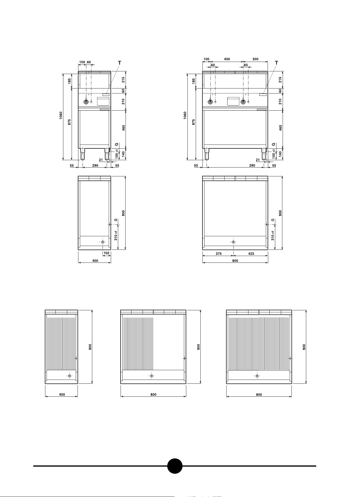
Dimensions
Gas connection
G
Data plate
T
014-03 - Gas fry-top
4
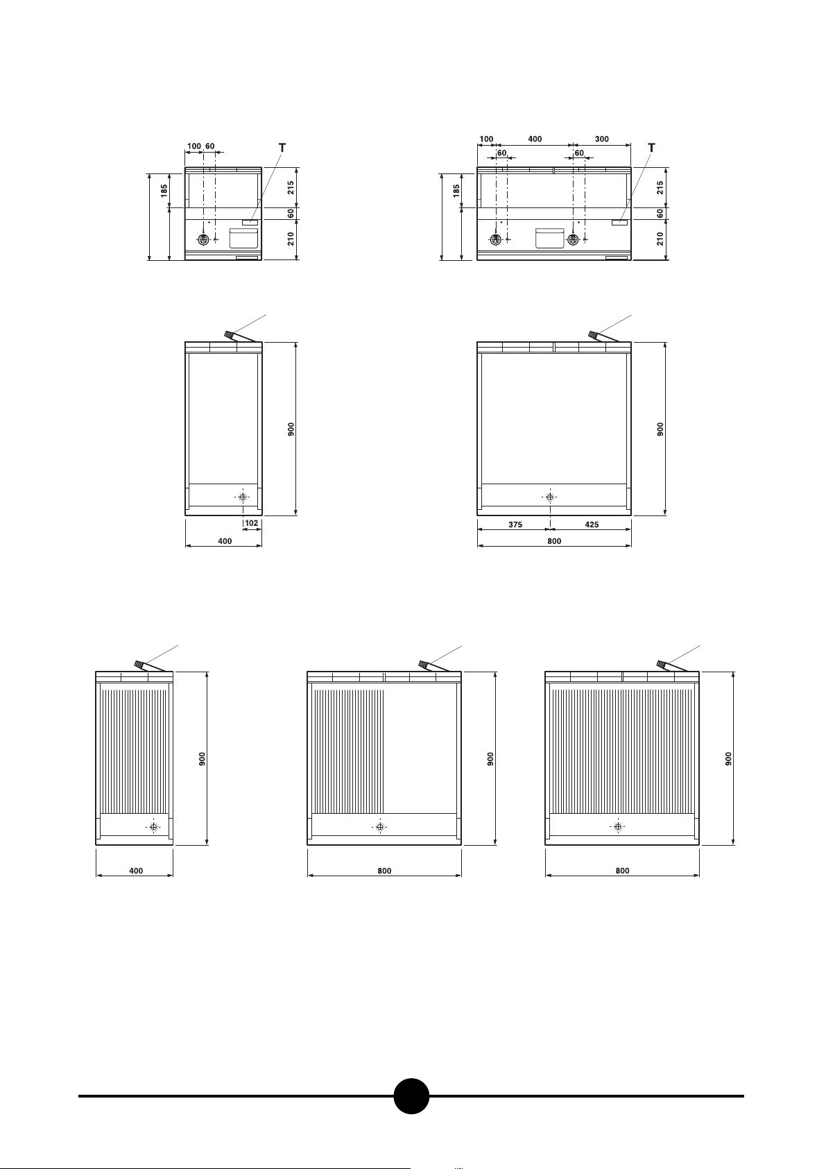
Dimensions
455
270
AGB 455/WP
AGB 457/WP
455
270
G
G
AGB 459/WP
AGB 461/WP
G
AGB 463/WP AGB 465/WP
(AGB 467/WP)
Gas connection
G
Data plate
T
G
G
AGB 470/WP

014-03 - Gas fry-top
5
2 - CHARACTERISTICS OF THE APPLIANCES
The instructions contained in this manual apply to our gas
fryers in the II2H3+ category (see table on page 6).
control panel. It contains all necessary reference data such as the
name of the manufacturer, input pressure, gas type setting, etc.
The data plate is located on the front of the appliance and on the
CAT/KAT GAS/GAZ G30 G31 G20 G25
II2H3B/P P mbar 30 30 20 -
II2H3+ P mbar 30 37 20--
II2H3+ P mbar 28 37 20 -
0051
TIPO/TYPE
MOD.
ART.
N.
N.
Qn kW
MOD.
V AC kW Hz
THE APPLIANCE MUST BE CONNECTED IN COMPLIANCE WITH THE LAWS IN FORCE
AND INSTALLED IN A WELL-VENTILATED ROOM. READ THE INSTRUCTION MANUALS
BEFORE INSTALLING AND USING THE APPLIANCE.
THE APPLIANCE MUST BE INSTALLED BY QUALIFIED PERSONNEL.
m3/h
II2ELL3B/P P mbar 50 50 20 20
II2E+3+ P mbar 28 37 20 25
II2H3B/P P mbar 50 50 20 -
I2E P mbar - - 20 -
--II2H3B/P P mbar 30 30
II2H3+ P mbar 28 37 20 -
I3B/P P mbar 30 30
I3+ P mbar 28 37
Predisposto a gas: - Gas preset: - Prevu pour gaz:
Eingestelt für Gas: - Preparado para gas: -
--
--
Geschuckt voor:
SE FI DK CZ SK SI
IT CH PT
ES IE GB GR
NL
25II2L3B/P P mbar 30 30
DE
FR BE
AT CH
LU
EE LV LT
EE LV LT
NO MT CY IS HU
CY
MADE IN ITALY
G30/G31 28/37 mbar
G20 20 mbar
Model
AGB 455/WP
AGB 457/WP
AGB 463/WP
AGB 459/WP
AGB 461/WP
AGB 465/WP
AGB 467/WP
AGB 470/WP
3 - TECHNICAL DATA
Description
Gas fry top - smooth plate
Gas fry top - smooth chromium top plate
Gas fry top - grooved plate
Gas fry top - smooth plate - 2 cooking zones
Gas fry top - smooth chromium top plate - 2 cooking zones
Gas fry top - grooved plate - 2 cooking zones
Gas fry top - 1/2 smooth + 1/2 grooved plate - 2 cooking zones
Gas fry top version - 1/3 grooved + 2/3 smooth plate - 2 cooking zones
Gas fry top - smooth plate
Gas fry top - smooth chromium top plate
Gas fry top - grooved plate
Gas fry top - smooth plate - 2 cooking zones
Gas fry top - smooth chromium top plate - 2 cooking zones
Gas fry top - 1/2 smooth + 1/2 grooved plate - 2 cooking zones
Gas fry top version - 1/3 grooved + 2/3 smooth plate - 2 cooking zones
Gas fry top - grooved plate - 2 cooking zones
Dimensions
(LxPxH) - mm.
400 x 900 x 875 (1090)
400 x 900 x 875 (1090)
400 x 900 x 875 (1090)
800 x 900 x 875 (1090)
800 x 900 x 875 (1090)
800 x 900 x 875 (1090)
800 x 900 x 875 (1090)
800 x 900 x 875 (1090)
400 x 900 x 270
400 x 900 x 270
400 x 900 x 270
800 x 900 x 270
800 x 900 x 270
800 x 900 x 270
800 x 900 x 270
800 x 900 x 270
N.
51BQ2910
51BQ2910
51BQ2910
51BQ2910
51BQ2910
51BQ2910
51BQ2910
51BQ2910
51BQ2910
51BQ2910
51BQ2910
51BQ2910
51BQ2910
51BQ2910
51BQ2910
51BQ2910

014-03 - Gas fry-top
6
Model
TABLE 1
AGB 455/WP - AGB 457/WP
AGB 463/WP
AGB 459/WP - AGB 470/WP
AGB 471/WP - AGB 465/WP
AGB 467/WP
Category
Construction type
Air necessary for combustion
Nominal thermal power
Minimum thermal power
Connection pressure
Methane gas 2H
Liquid gas 3+
Gas connection values
Methane gas 2H
Liquid gas 3+
Nozzles Ø 1/100 mm
G20
Main burner
G30/31
No. of nozzles, pilot burner
G20
G30/G31
(HuB = 9.45 kWh/m
(HuB = 12.87 kWh/kg) kg/h
Nominal capacity
Low flame
Nominal capacity
-
G20
G30/G31
II2H3+
A
3
/h
m
kW
kW
20 mbar
28/37 mbar
3
) m3/h
13
6.2
2.6
0.66
0.48
165 R
adjustable
120
-
36
19
26
6.2 + 6.2 = 12.4
2.6 + 2.6 = 5.2
1.31
0.97
2 x 165 R
adjustable
2 x 120
-
2 x 36
2 x 19
Primary air distance “A”
Methane gas G20
Liquid gas G30/G31
15
19
15
19

014-03 - Gas fry-top
7
Construction, equipment installed and
safety devices
Robust steel frame, with 4 legs (adjustable in height).
18/10 chrome-nickel steel outer panelling.
The surface of the special steel plate can be either
smooth or grooved; the plate comes with side and back
splash-guards made of 18/10 chrome-nickel steel.
The appliance is also fitted with a stainless steel fat tray.
The plate is heated by tubular chromium-plated steel burners, built to withstand thermomechanical stress.
The pilot burner has fixed injectors.
The combustion chamber and flues are made of electrogalvanised steel sheeting.
The temperature may be adjusted through special cocks
with thermostats, complete with safety devices.
It goes from low (minimum) to high (maximum) through a
range of easily selectable intermediate levels.
Our fry-tops are available either with a grooved or with a
smooth surface.
Models AGB 459/WP - AGB 470/WP - AGB 461/WP AGB 465/WP - AGB 467/WP have two separate grilling
areas on the plate. Each area has its own temperature
controls.
Location
The appliance should be installed in a well ventilated
room, and if possible under a range hood.
The appliance can be installed on its own or alongside
other equipment.
If the appliance is to be installed near inflammable walls,
a minimum distance of 200 mm around the sides and
back should be allowed.
If this is impossible, take proper steps to ensure the installation is safe, such as fitting tiles or heat-reflecting material to the walls
Before connecting up the appliance to the gas supply,
check on the data plate that the appliance is fitted for the
type of gas available.
If not, consult paragraph “Running the appliance on other
types of gas”, page 9.
Legal and technical requisites
During assembly, the following legal and technical requisites should be adhered to:
- relevant national legislation;
- local building and fire safety regulations;
- worksheet “Technical rules for installing gas”;
- worksheet “Technical rules for LP gas”;
- worksheet “Gas installations in industrial kitchens”;
- industrial injury legislation;
- local Gas Board regulations;
- current CEI regulations.
INSTALLATION
Assembly, installation and maintenance, i.e.: assembly,
connecting the gas supply, checking power rating, transforming or adapting the appliance to run on other types of
gas, and commissioning, must all be done by contractors
authorised by the local Gas Board in accordance with local and national legislation.
Before doing anything else, seek advice from your Gas
Board.
Installation procedure
To level the appliance correctly, adjust the height of the four
legs.
The R 3/4” gas off-take on the appliance can either be
permanently fixed to the mains or made detachable using a
standard gas tap.
If flexible hose is used, it must be in stainless steel and to
DIN 3383 part 1 or DIN 3384 standard.
After completing connection, check for leaks using a
special leak-detector spray.
Gas venting
These appliances are A construction type, thus no gas
venting is required.
For advice on ventilating the premises where the appliance
is installed, observe current regulations.
OPERATING INSTRUCTIONS

014-03 - Gas fry-top
8
Before commissioning the appliance
Before commissioning the appliance, remove the protective wrapping.
Thoroughly clean the work-surface and the outside of the
appliance using lukewarm water and detergent.
With a damp cloth eliminate all traces of the rust-proofing
applied in the workshop then dry with a clean cloth.
Start-up
Before starting the appliance up, check that its specifications (category and type of gas used) match those of the
family and group of the gas available locally.
If not, adapt the appliance to the gas family or group required (see paragraph “Running the appliance on other
types of gas”, page 9).
To start the appliance up, see the instructions for regular
use.
Testing the power rating
Use the specific nozzles for the nominal capacity on the
appliance.
Capacity can be of two types:
- nominal, as given on the data plate;
- minimum.
These nozzles are shown in “TECHNICAL DATE” table 1.
The following are the operating pressure tolerances to obtain the nominal power according to the agreed nozzles:
- from 15 to 22.5 mbar for gases of the second family
- from 25 to 35 mbar for gases of the third family
(propane).
The appliance will not work outside the above pressure
threshholds.
To adjust the capacity to its minimum value, use the data
in tables 1.
If you wish to check the nominal capacity further, you may
do so using a gas meter according to the so-called ”volumetric method”.
It is normally enough, however, simply to check that the
nozzles are functioning correctly.
Checking input pressure (Fig. 3)
Input pressure should be measured using a gauge (e.g. a
gooseneck pipe, min. resolution 0.1 mbar).
Remove screw (22) from the pressure socket and connect it to the tube on the gauge; after measuring, the
screw should be retightened absolutely airtight (22).
Checking power rating using the
volumetric method
Using a gas meter and a chronometer, you can read the
volume of gas output per time unit.
The correct volume will be the value of “E” expressed in litres per hour (It/hr) or litres per minute (It/min).
The following formula is used to calculate the value of “E”:
Capacity should only be measured when the appliance is
at a standstill.
The heat value can be obtained from your local Gas
Board.
To obtain the nominal and minimum capacities in relation
to the nominal pressure, consult table 1.
WARNING
It is not possible to adjust nominal capacity in advance.
Checking power rating when using LP
gas
Check that the type of nozzles used match manufacturer's
specifications.
Check that the output pressure regulator installed collaterally to the plant conforms to the specifications laid down
in paragraph "Testing the power rating" (see data plate or
measure the pressure) page 8.
Capacity
Heat value
E =
COMMISSIONING THE APPLIANCE
3
Smooth, grooved and
chrome-plated plates
with THERMOSTATIC
VALVE
21
22
16 17
1

014-03 - Gas fry-top
9
Checking the pilot light
When correctly adjusted, the pilot light flame will completely surround the thermocouple and will not flicker; if it
does, make sure that the nozzle is the correct one for the
type of gas used.
Checking the primary air
The plates, whether smooth or grooved, can be adjusted.
The air flow is correctly adjusted when there is adequate
protection against the flame rising when the burner is cold
or flareback when it is hot.
Checking the functions
- Start the appliance in accordance with the
instructions;
- Check the gas tubes for leaks;
- Check that the flame on the main burner lights
properly and is correctly formed, even on low;
- Check that the pilot light is correctly regulated;
- Draw up a servicing and maintenance contract.
Note for the installer
- Explain and demonstrate to the user how the machine
works according to the instructions, and hand him this
manual.
- Remind the user that any structural alterations to the
room housing the appliance may affect the combustion
air supply. Once the alterations have been completed,
the appliance and its functions should be thoroughly
checked.
Running the appliance on other types
of gas
When changing to another type of gas, e.g. from natural
to LP, or to another gas group, consult the “TECHNICAL
DATA” to determine the correct nozzles to use.
The nozzles for the main burners and pilot light for diffe-
rent types of gas, marked in 100ths of mm, are in a case
supplied with the appliance (the pilot burner nozzles are
marked with a code number).
When the appliance has been transformed or adapted,
recheck its functions as described in paragraph
"Checking the functions".
Replacing the main burner nozzle
To change nozzle (30), pull out the fat tray and loosen the
fixing screws holding the control panel in place.
Remove the panel. Unscrew the nozzle from the nozzle
holder with an adjustable spanner; replace with a new
nozzle (see “TECHNICAL DATA” table).
To make changing the nozzle easier, loosen screw (39) to
push the air adjustment sleeve back.
After fitting the nozzle, reset primary air distance “A” (see
“TECHNICAL DATA” table).
Replacing the pilot burner nozzle
(Fig. 5)
To get at the pilot burner, slide out the fat tray and remove
the control panel (as previously described).
The pilot burner has a fixed gas supply.
To change to another type of gas, replace the nozzle on
burner (36) according to the type of gas used, by loosening hose (35) (see “TECHNICAL DATA” table).
Adjusting the low flame (Fig. 3)
Referring to the “TECHNICAL DATA” table, set the low
flame screw (36) as follows:
- if the appliance is to run on LP gas, tighten the low
flame screw as far as it will go;
- if the appliance is to run on natural gas, turn the low
flame screw while simultaneously adjusting the primary
air:
- read off the setting in It/min which corresponds to the
heat value (calculated by the “Volumetric Method”) in
2
29314028 30
39
26

014-03 - Gas fry-top
10
the Gas Flow Setting Table (2);
- start the appliance up according to the instructions;
- after allowing the appliance to run for 45 mins., turn
the knob to low and set minimum gas flow by turning
screw (36) (to the right = gas flow decreases; to the left
= gas flow increases).
On models AGB 459/WP - AGB 470/WP - AGB 461/WP AGB 465/WP - AGB 467/WP each burner must be adjusted separately.
MAINTENANCE
The following maintenance programme should be carried
out at least once a year:
- Check that all the safety and setting devices are
working properly;
- Check that the burners are working properly with re-
gard to:
- ignition
- combustion safety;
- Check the functions of the appliance as described in
paragraph "Checking the functions" page 8.
If the main burner needs cleaning, proceed as follows:
a) remove the control knobs and the fat tray; unscrew
the fixing screws and remove the control panel;
b) unscrew hose clamp (28, Fig. 2) to disconnect the
gas vent connector from the nozzle holder;
c) unscrew the fixing screws and remove the front pa-
nel of the combustion chamber; then loosen the burner
fixing screws.
The main burner can now be removed for cleaning.
Take care when cleaning the flame apertures.
Make sure you use a prong with the right diameter.
When reassembling the burner, make sure the back
slots properly into the combustion chamber.
- Check the gas venting path (make sure the gas is
correctly evacuated).
REPLACING PARTS
All parts must be replaced by authorised technicians
only!
To replace the following parts, first remove the control
knobs, slide out the fat tray and remove the control panel
(after unscrewing its fixing screws).
Ignition plug (Fig. 5)
The ignition plug (37) must be removed from below.
Disconnect the ignition lead, loosen the lock nut and insert a new plug.
Gas tap (Fig. 3)
Loosen the gas piping and thermocouple hoses, then loosen the screws fixing the gas supply to the gas ramp and
insert a new tap.
Thermocouple (Figs. 3 & 5)
Loosen the nipples fixing the thermocouple to the gas cock
and to the pilot lamp; insert the new part.
After replacing the parts, fit the control panel and its parts
back in the right order.
WARNING
Every time a replacement involving gas input parts is
made, recheck all functions and test for leakage.
5
37
29
34
36
35

USING THE APPLIANCE
014-03 - Gas fry-top
11
4
Thermostatic valve
SMOOTH GROOVED AND CHROME
PLATES START-UP
(With thermostatic valve)
FIRST-TIME USE OF THE PLATE
Important!
Before using the appliance for the first time, thoroughly clean the smooth or grooved surface of the plate
with lukewarm water and detergent, using a soft cloth
to eliminate all trace of the rust-proofing applied in the
workshop. Dry with a clean cloth.
IGNITION
Turning the pilot burner on (Fig. 4)
Press knob (4) and turn it to the left .
Keep the knob pressed down while repeatedly pressing
piezo ignition button (6) until you can see through aperture
(10) on the control panel that the flame has caught. Keep
the knob pressed down for another 15-20 seconds; if the
flame goes out after the knob is released, start again.
Turning the main burner on and
adjusting the temperature (Fig. 4)
To light the main burner, turn the knob on the left further
to reach desidered position.
The thermostat has 8 positions, from 1 to 7; the indicative
values of temperature for each positon are the following:
Position degrees °C
1 160
2 175
3 195
4 220
5 240
6 265
7 290
- The minimum for the thermostatic valve is in position 1
and the maximum in position 7
TURNING THE APPLIANCE OFF
Turning the appliance off during
normal operation
To turn the main burner off only, simply turn the knob
to ; this way only the pilot burner will stay on.
To turn the appliance off completely, turn the knob to ●;
this will turn the pilot burner off as well.
Turning the appliance off in an
emergency
In an emergency turn off the gas supply.
10
5
4
6

014-03 - Gas fry-top
12
What to do if something goes wrong
or if not using the appliance for a
long time
If the appliance is not to be used for a long time, or if it
breaks down or works incorrectly, close the tap to the gas
mains located outside the appliance.
If anything goes wrong, call the aftersales department.
TAKING CARE OF THE APPLIANCE
FREQUENCY OF MAINTENANCE
Smooth/grooved surface
After using the grilling plate, clean its surface while it is
still quite warm. Use emery paper or steel wool.
To prevent rust from forming, spread a thin coating of vegetable oil over the grilling plate after cleaning.
The fat tray should be emptied and cleaned daily after
use.
Giving the appliance a thorough clean every day (after
turning it off) will keep it in perfect working order and
make it last longer.
All steel parts should be cleaned with water and a detergent, using a damp cloth; do not use abrasive substances or corroding detergents. Do not use steel wool
anywhere but on the grilling plate since this might cause
rust.
For the same reason, avoid touching the appliance with
anything made of iron.
Do not clean any parts of the appliance other than the
grilling plate with emery or sandpaper. If absolutely necessary, you may use powdered pumice stone.
If the appliance is extremely dirty, use a synthetic sponge
such as Scotchbrite.
After cleaning the appliance, rinse with clean water and
dry with a clean cloth.
All maintenance work must be carried out by qualified
personnel only.
Have the appliance checked at least once a year; we
strongly recommend that you stipulate a servicing and
maintenance contract with your supplier.

014-03 - Gas fry-top
13
WARNING
DUE TO ITS POLICY OF CONTINUAL PRODUCT IMPROVEMENT, THE MANUFACTURER RESERVES THE RIGHT
TO MAKE ANY CHANGES DEEMED NECESSARY.
THE MANUFACTURER CANNOT BE HELD RESPONSIBLE IF THE INSTRUCTIONS CONTAINED IN THIS MANUAL ARE NOT OBSERVED.
WHIRLPOOL EUROPE srl
V.le Guido Borghi, 27
I – 21025 Comerio – VA
 Loading...