

Whirlpool ACK2430, ACK2635, ACK3551, ACK3411, ACK3654 Installation Use And Care Manual
INSTALLATION, USE AND CARE
MANUAL
BUILT IN
RANGES
THIS MANUAL CONTAINS IMPORTANT INFORMATION,
READ IT BEFORE FIRST USE OF YOUR RANGE
Part No. 98015094 Rev. Rel
Printed in Mexico 2003
STM00347 Rev. Rel.
Covers
the following
models:
ACK2430
ACK2635
ACK3411
ACK3551
ACK3654
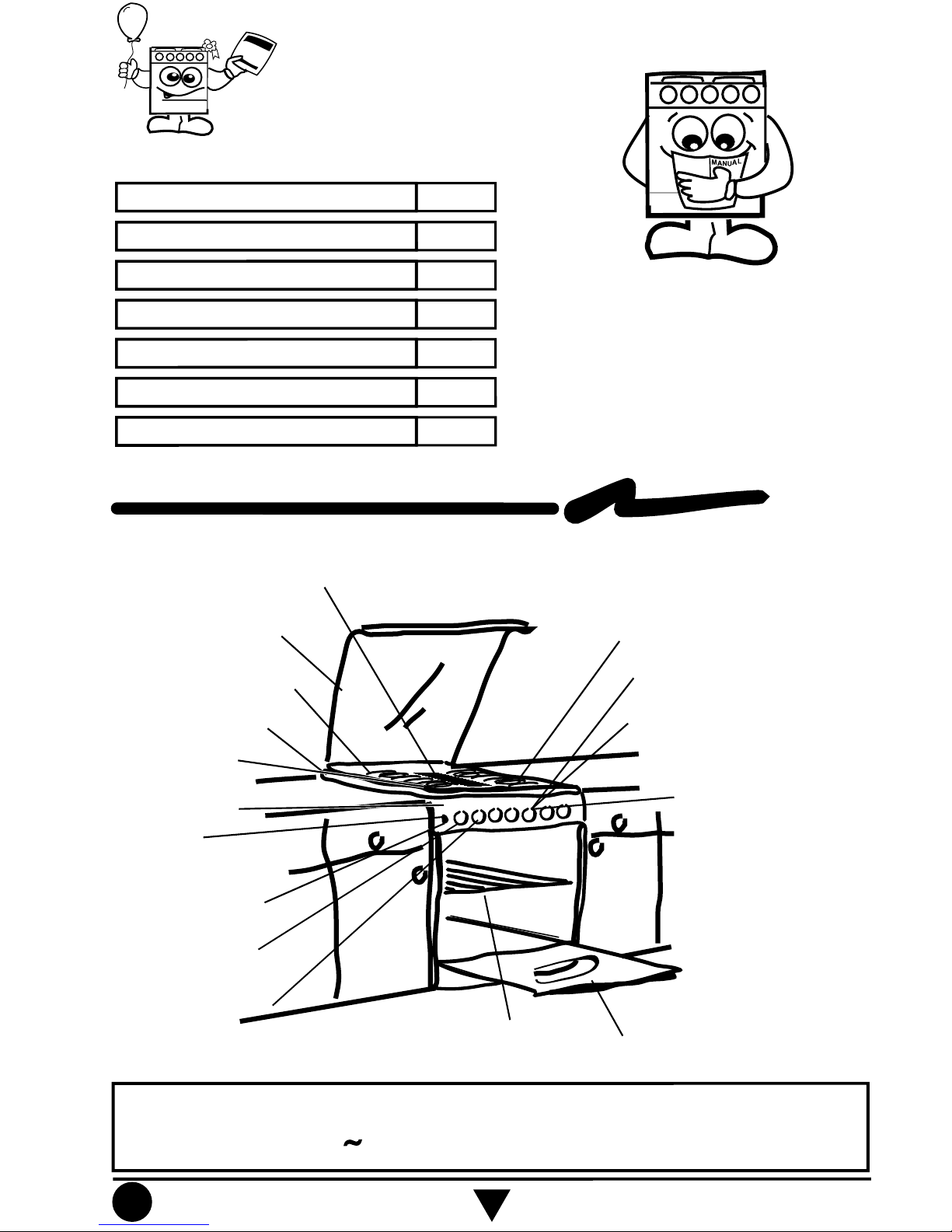
Parts and Features
¡ Congratulations !
2
This range was carefully manufactured with
the latest technical expertise. By purchasing
it, you have received quality; but remember,
quality requires maintenance.
Before you use your range, read the
instructions in this manual, the information
is important for best results in the use of
your range.
Top Burners
Griddle
Top Grates
Burner Valves
Oven
Rack
Oven
Door
Oven Light Switch
Cooktop
Electronic
Ignition
Super Burner
Glass Lid
127 V ± 10% 50/60 Hz 1,0 A Max.
Electrical Characteristics for the models ACK2430, ACK2635, ACK3411, ACK3551 &
ACK3654:
Manifold Panel
4 Steps Oven
Thermocontrol without Pilot
(O
nly in m
odels ACK3411 & ACK3654)
(O
nly in m
odels ACK2635, ACK3551,
ACK3654 & ACK3411)
(O
nly in m
odels ACK2430, ACK2635,
ACK3551 & ACK3654)
(O
nly in m
odel ACK3654)
(O
nly in m
odel ACK3654)
(O
nly in m
odels ACK3551, ACK3411
& ACK3654)
Xpress
Super Safe
Knob
(O
nly in m
odel ACK3654)
Parts and Features
Installation & Gas Connection
How to Use Your Range
Cleaning and Maintenance
Warranty
Identification Format
Authorized Service Centers
Page
2
3
7
12
15
15
16
Index
Oven Thermocontrol
(O
nly in m
odels ACK2430 & ACK3551
Thermostat with Pilot
(Only in m
odel ACK2635 )
Install your range in an area that is protected against weather exposure.
Do not allow range to be used by children or unqualified adults.
Provide for adequate maintenance.
Use the range only in home applications. It is not designed for commercial use.
!
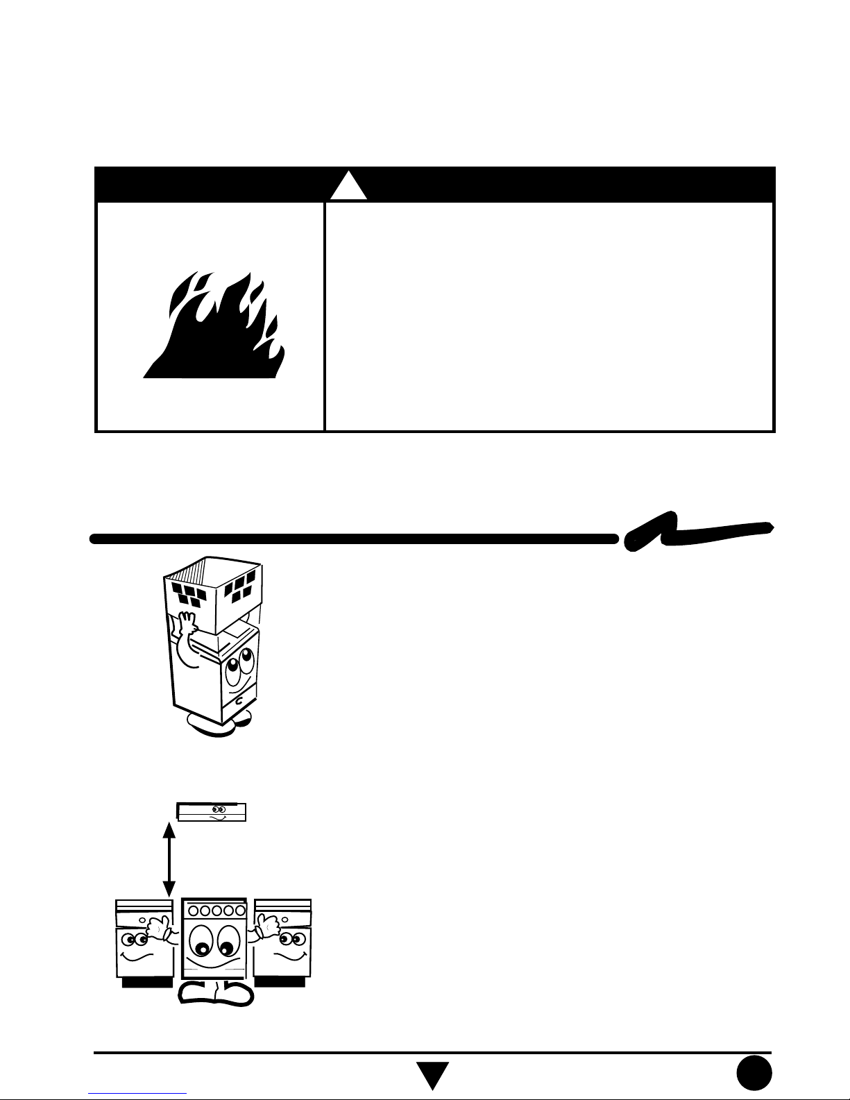
Do not allow children to use or play with the range;
keep children away while range is in use.
Keep the range surroundings free of flammable material,
gasoline and other vapors or flammable liquids.
Do not get too close to the flame produced by the
burners or wear loose clothing; your clothes may ignite
if contact by open flames.
Do not use your range to warm rooms, because this is
dangerous.
Failure to do so can result in death, fire or explosion.
WARNING
Fire or Explosion Hazard
Installation and Gas Connection
EXHAUST DEVICE
61 cm
min.
Proper installation is your responsibility. A
qualified technician or Service technician must
install this range.
Remove all packing material and put the range
accessories in their places.
Select the best location in your kitchen for your
range, protected from wind and with enough
space to open the oven door.
Do not install cabinetry directly above the range.
If you will install an exhaust device, put it at 61
cm minimum from the range cooktop.
If your range has a power cord, it must be
installed near an electrical wall outlet.
Do not use extension cords or multiple outlets.
3
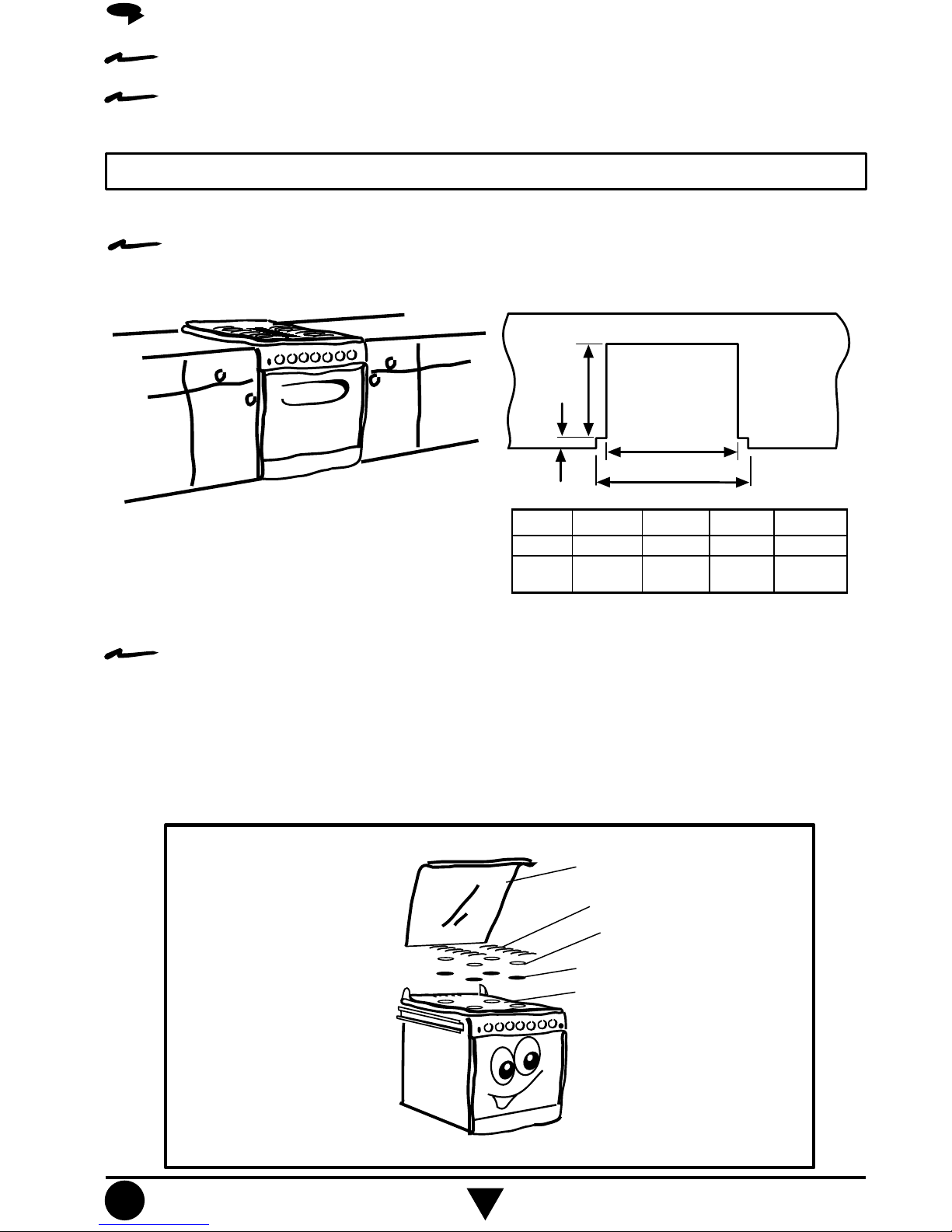
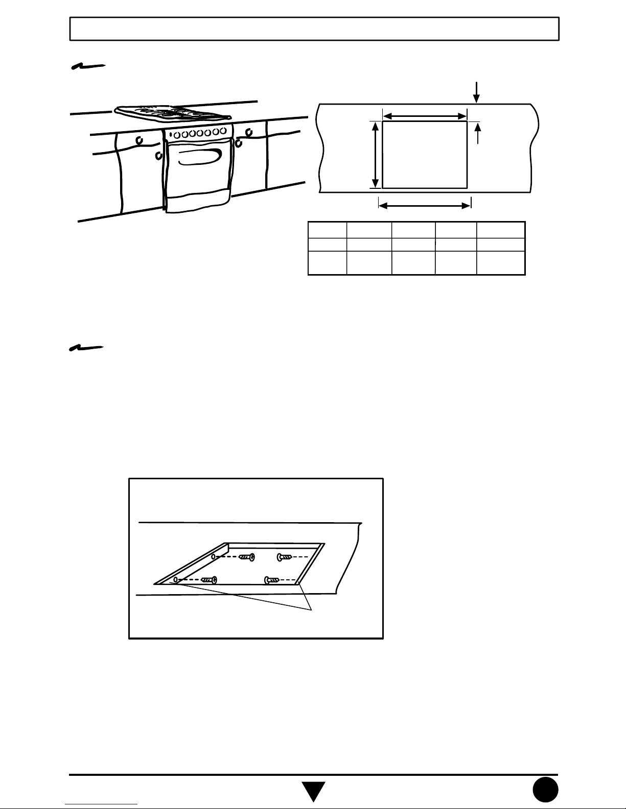
RANGE INSTALLATION ON THE COUNTERTOP:
The installation should be done by a qualified person.
The range is prepared at the factory to be installed as Slide In.
Slide - In Installation
Prepare the kitchen cabinets:
CUTS NEEDED ON THE
COUNTERTOP.
A
B
C
D*
30 510 25.0 768 812
20 510 25.0 509 552
Range
Dim. A Dim. B Dim.C Dim. D*
Size
Dimensions are in millimeters
NOTE: Dimension D* = Distance between cabinets.
Prepare the range:
- Remove the top grates, the top burners and the burners caps.
- Slide the range on the countertop allowing a space between the range and the back
of the countertop.
- Connect the range to the gas supply as shown in the page 6 and verify that there
are no gas leaks using soap solution.
- Connect the electrical power cord (if your model has electrical features).
- Slide the range to the back of the countertop.
- Replace the burners, burner caps and the grates.
Glass Lid
4
Top Grates
Burner Caps
Top Burners
Cooktop
Drop - In Installation
Prepare the kitchen cabinets:
NOTE: Dimension D* = Distance between cabinets.
Prepare the range:
CUTS NEEDED ON THE
COUNTERTOP.
C
B
A
D*
30 518 50 723 812
20 518 50 464 552
Tamaño
Dim. A Dim. B Dim.C Dim. D*
de
Estufa
Dimensions are in millimeters.
- Remove the glass lid (according to the model), the top grates, the top burners and the
burner caps.
- Remove the visible screws on the cooktop.
- Remove the Venturi tubes (these are the tubes that provide the gas to the burners) and
the cooktop moving it from right to left while you lift the cooktop to release the clips.
- Disconnect the spark plugs wires from the ignition module (according to the model).
- Remove the side channels and fix them to the counter top using the same screws
provided with the range (see the illustration).
Counter Top
Side Channels
5
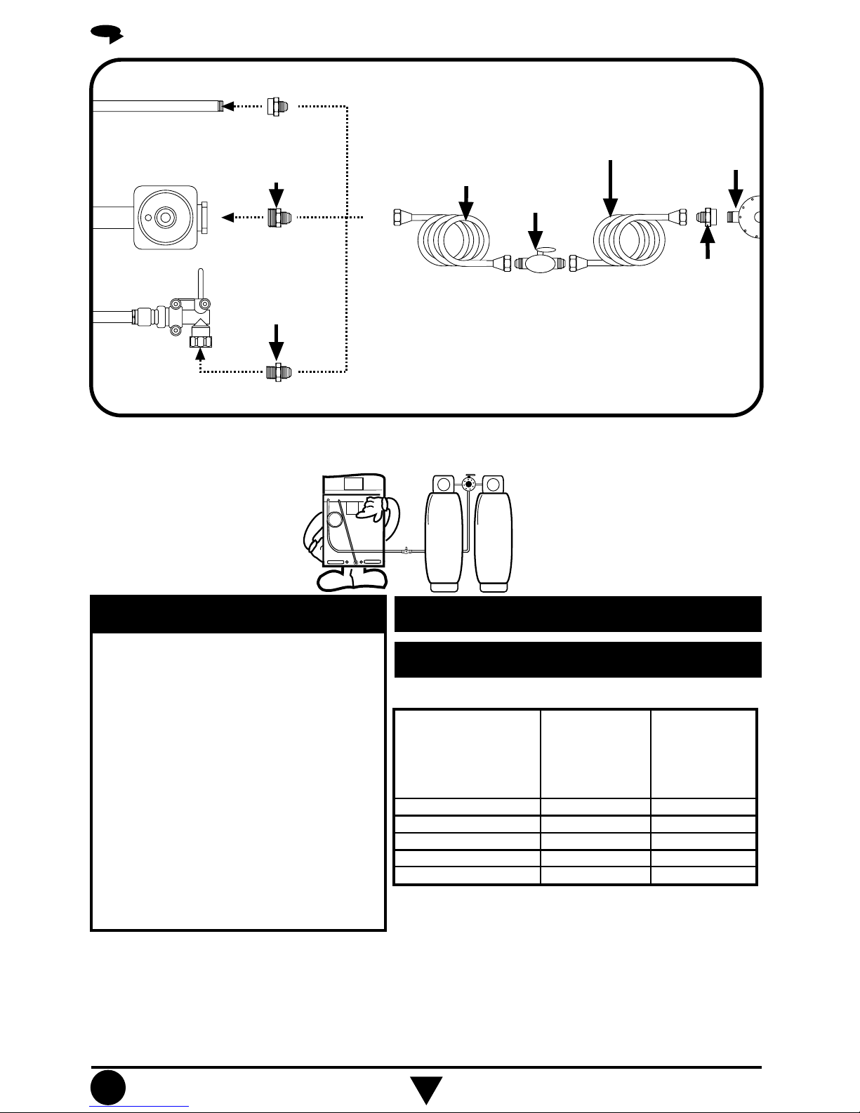
GAS SUPPLY CONNECTION
Gas Inlet Tube Fitting
integrated to the range
Gas Regulador
integrated to the
range
Shut Off Gas
Valve
integrated to the
range
3/8" NPT to 3/8" brass pipe
fitting Hex. adapter
1/2" NPT to 3/8" brass
pipe fitting Hex. adapter
3/8" NPT to 3/8" brass
pipe fitting Hex. adapter
If the installation is not
new, you should clean
it in order to avoid the
obstruction of orifices
and/or pilots.
3/8" copper pipe
with 5/8" flared
type nut or
metallic flexible
hose for gas
3/8" shut off
valve
NOTE: The material shown for installation is not provided with the
range.
NOTE: The range could be equipped from the factory with
one of the following accesories:
1.- Gas Inlet Tube Fitting or
2.- Gas Regulator or
3.- Shut Off Gas Valve.
3/8" copper pipe with
5/8" flared type nut.
Necessary
length to reach the
gas
Gas
regulator
3/8" brass pipe
fitting
Hex. adapter
To make it easier to move the
appliance, the installer should
loop the 3/8" copper tubing as
shown in the illustration.
IMPORTANT
This range is adjusted at the factory
for use with L.P. gas.
To use this range with natural gas,
you must replace the surface and oven
burner orifices, call Servicio AcrosWhirlpool, the phone number is shown
in the page 16. The technician must
make sure that the connections have
no leaks and the gas pressure in the
range is the same as shown in the
charts.
GAS L.P. OPERATING PRESSURE
11 inches Water Column
NATURAL GAS OPERATING
PRESSURE
7 inches Water Column
Conversion Gas Chart:
Kit to convert
from Natural
Gas to LP Gas
98015084
98015085
98010686
98015086
98014290
Range Model
Modelo ACK2430
Modelo ACK2635
Modelo ACK3411
Modelo ACK3551
Modelo ACK3654
Kit to convert
from LP Gas to
Natural Gas
98015081
98015082
98014570
98015083
98014571
This kit is available at your nearest Authorized
Service Center.
6
How to Use Your Range
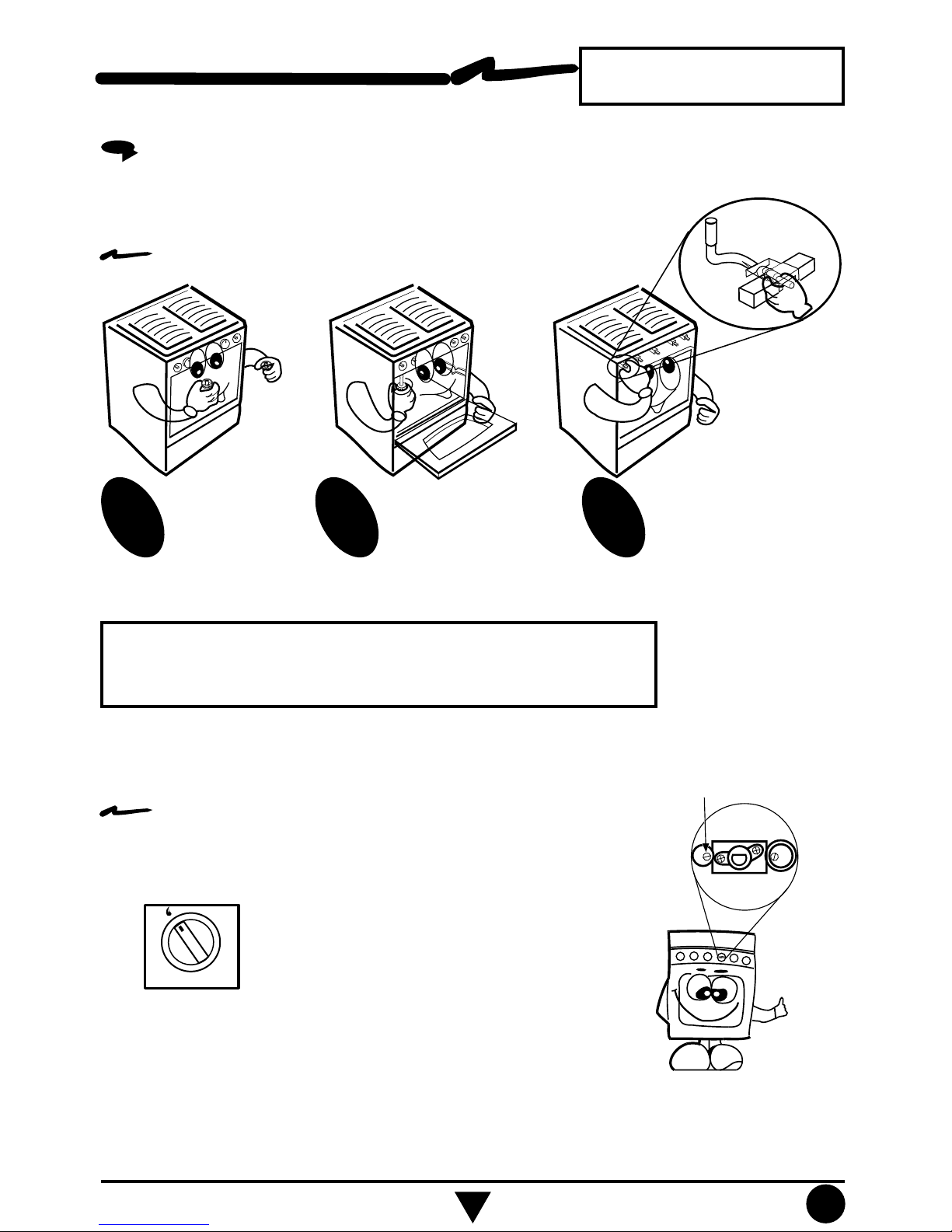
HOW TO ADJUST THE FLAMES AND OVEN PILOT
If the range has yellow flames, it may
require adjustment to the air shutters:
How to adjust the air for surface burners:
NOTE: Do not obstruct the gas
exhaust of the oven or broiler
Remove the
knobs.
1
NOTE: Because of different altitudes above sea level and variations
in the supply of gas, you may need to adjust the main air intake
to the burners. This will result in a better air-gas mixture and thus
a better operation.
The models with thermostat have a pilot in the oven burner,
to adjust it:
1.- Without the manifold panel, locate the adjustment screw on
the thermostat, see the illustration on the right side.
2.- Remove the oven tray (see page 12) and turn the knob
approximately 30° until you feel a small stop,
turn the oven pilot on with a match or a lighter.
2
Unscrew the screws
of front and below the
manifold panel and
remove it.
3
Adjust the air shutters
individually. Light the
burner, then push or pull
the air shutter until you
get a blue flame.
ADJUSTABLE FLAT SCREW
FOR THE OVEN PILOT
Pilot Position
3.- With a flat and thin screwdriver turn the adjustment screw
until you get a flame approximately 3/8" tall.
4.- Replace the manifold panel, screws and knobs.
7
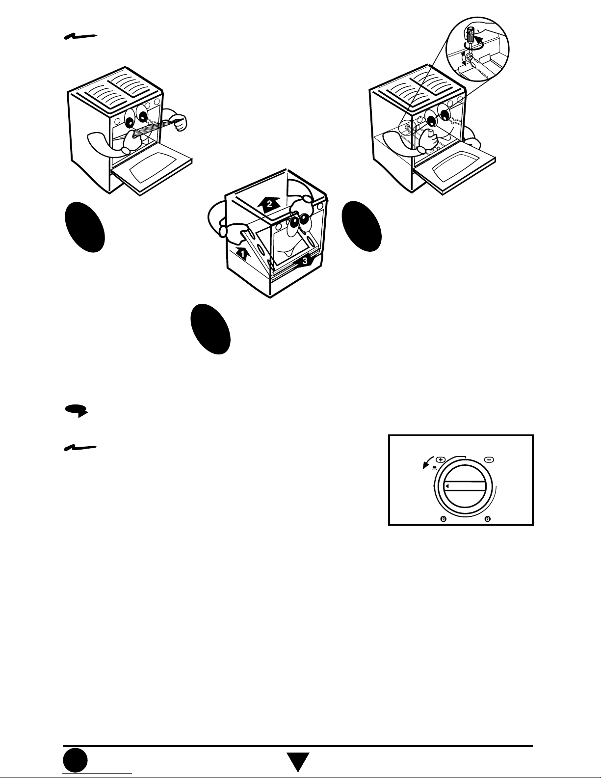
How to adjust the oven burner air shutter:
Remove the
oven rack.
(See page 10).
1
Remove the oven
tray. (See page 12).
3
2
HOW TO TURN ON THE SURFACE BURNERS MANUALLY
To turn on the surface burners manually:
Light a match and place it close the burner while you
push and turn the knob 1/4 of the way, the burner will
light immediately.
A - Locate the screw on
the air shutter and
loosen it.
B - Turn around the air
shutter.
C - Turn on the oven.
D - Verify that the flames
are blue.
E - If the flames are not
blue, repeat since
step B, when the
flames are adjusted,
tighten the screw
again.
F - Replace the oven tray
and the oven rack.
MAXIMUM
FLAME
OFF
MINIMUM
FLAME
8
Knob in ignition position.
9
To turn on the surface burners with independent
electronic ignition:
Some models (see page 2) have independent
electronic ignition, to operate it push the button
located on the left side of the manifold panel
while you push and turn the desired knob.
Release the ignition button when the burner
lights.
Knob in ignition position.
OFF
MINIM
UM
FLAM
E
M
AXIM
UM
FLAM
E
ELECTRO
NIC IG
NITIO
N
BUTTO
N
SURFACE BURNERS WITH ELECTRONIC IGNITION
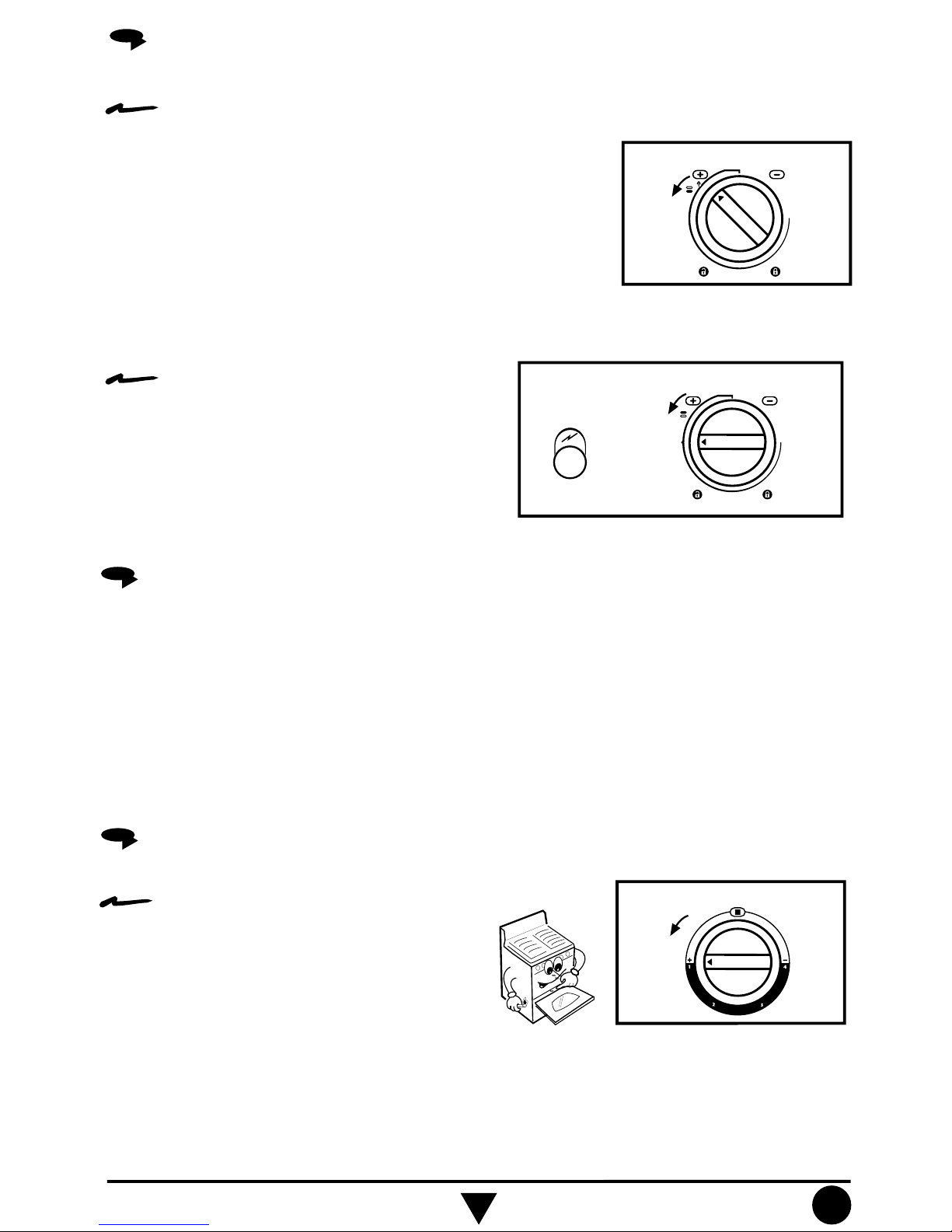
To turn on the surface burners with electronic
ignition in the knob:
1.- Some models (see page 2) have electronic ignition
integrated in knobs, to operate push and turn the
desired knob to the ignition position. (See illustration).
2.- To stop the sparks turn the knob to the
maximum flame position.
O
FF
MINIM
UM
FLAM
E
MAXIM
UM
FLAM
E
Knob in ignition position.
GRIDDLE
In order to protect the griddle finish, it is recommended to use a small quantity of fat,
butter or vegetable oil before using it.
Use plastic utensils to protect the griddle against scratches.
Do not use abrasive materials, steel or plastic fibres to clean it.
Use only cloth or sponge, soap or detergent and rinse with water.
stylem
aster
98013014 R.0
How to light the oven burner with thermocontrol,
manually:
O
FF
MINIM
UM
FLAM
E
MAXIM
UM
FLAM
E
Knob in ignition position.
OVEN WITH THERMOCONTROL
1.- Open the oven door, light a match and
place the flame at the igniter hole in the
front of the oven tray while you push in and
turn the oven knob 1/4 of the way, the
burner will light immediately.
2.- Verify that the oven burner has been ignited.
stylemaster
98013014 R.0
10
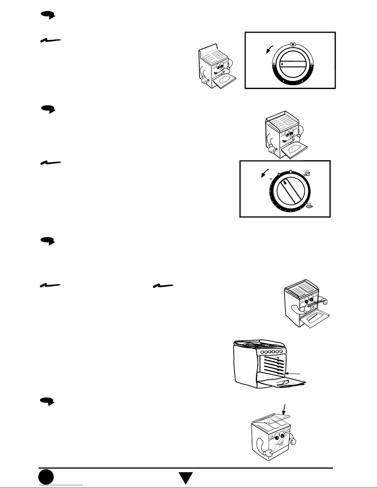
How to light the oven burner with thermocontrol,
manually:
OFF
MINIM
UM
FLAM
E
M
AXIM
UM
FLAM
E
Knob in ignition position.
OVEN WITH 4 STEPS THERMOCONTROL WITHOUT PILOT
GLASS LID
Some models (see page 2) include a glass lid.
The glass lid is made of resistant tempered glass, it should be
handled with care to avoid breaking the glass. Open or close
the glass lid with care.
G
LASS LID
OVEN RACK
The oven has 4 different supports for the oven rack, this rack has a stop to avoid droping
from the oven, to change the rack position follow the steps:
To remove the oven rack:
1.- Pull the oven rack until it
stops.
2.- Lift the front part.
3.- Pull it again until it is
released.
To install the oven rack:
1.- Push the oven rack until it
stops.
2.- Lift the front part.
3.- Push it again until it stops.
An extra rack position is provided for special cooking
operations other than baking, such as roasting, where a
large roasting container will require more heat and therefore
need to be closer to the heat source or oven bottom.
EXTRA RACK
PO
SITIO
N
1.- Open the oven door, light a match and
place the flame at the igniter hole in the
front of the oven tray while you push in and
turn the oven knob 1/4 of the way, the
burner will light immediately.
2.- Verify that the oven burner has been ignited.
Some models (see page 2) have a thermostat and pilot
to control the oven function.
How to light the oven burner with thermostat and
pilot:
1.- Open the oven door, light a match and place the flame
at the igniter hole in the front of the oven tray, push
and turn the oven knob to the pilot position.
2.- Turn the oven knob 1/4 of the way to ignite the oven
burner, this position is minimum flame.
3.- Verify that the oven burner has been ignited.
OVEN WITH THERMOSTAT AND PILOT
Knob on the m
ark of ignition.
140
160
180
200
225
250
stylemaster
98008356 R.0
stylem
aster
98010112 R.0
O
FF
 Loading...