

Page 1

ATA-171/172/171P (ATA-S1/S2/P)
User’s Guide
ATA-171/172/17
1P
(ATA-S1/S2/P)
User’s Guide
V.1.4
2006/4/24
0
Page 2

ATA-171/172/171P (ATA-S1/S2/P)
Introduction....................................................................................................................................... 2
1
1.1 Hardware Overview...............................................................................................................2
1.2 Software Overview................................................................................................................2
2 Keypad Interface for The ATA........................................................................................................... 3
3 Setup the ATA by Web Browser........................................................................................................ 4
3.1 Login......................................................................................................................................4
3.2 System Information for the ATA.............................................................................................5
3.3 Phone Book ...........................................................................................................................5
3.4 Phone Setting........................................................................................................................6
3.5 Network...............................................................................................................................12
3.6 IP Settings...........................................................................................................................16
3.7 NA T T rans...........................................................................................................................21
3.8 Others..................................................................................................................................22
3.9 System Auth........................................................................................................................25
3.10 Save Change ......................................................................................................................25
3.11 Update.................................................................................................................................26
3.12 Reboot.................................................................................................................................28
4 Setup the ATA by using Console (Hyper Terminal)......................................................................... 29
4.1 Configure the COM port......................................................................................................29
4.2 Login into the ATA...............................................................................................................30
4.3 Using CLI command to configure the ATA ..........................................................................31
5 How to make a phone call .............................................................................................................. 37
User’s Guide
1
Page 3

ATA-171/172/171P (ATA-S1/S2/P)
1 Introduction
This user’s manual is for 1-port FXS VoIP terminal adapter (AT A). This user’s manual will explain the IVR
instruction, web conf iguration, and command line configuration for the ATA. Before using the ATA, some
setup processes are r equired to make the ATA work properly. Please refer to the Setup Me nu for further
information.
1.1 Hardware Overview
The ATA has the following interfaces f or Networking, telephone interface, LED indication, a nd power
connector.
1.1.1 Two RJ-45 Networking inte r f ace, thes e t wo interfaces support 10/1 00M ps Fas t Et her net. you
can connect one RJ- 45 Fa s t Eth er net p ort to th e AD S L or Switch, and c on nect t he other one
to your computer.
1.1.2 One RJ-11 Type analog telephone j ack interf aces. You can connect one analog telepho ne to
the terminal adapter.
1.1.3 LED Indication: There ar e three LED indicat ors in the ATA to show the Power, Register, and
Off-Hook indication.
1.2 Software Overview
Network Protocol Tone
User’s Guide
• SIP v1 (RFC2543), v2 (RFC3261)
• IP/TCP/UDP/RTP/RTCP
• IP/ICMP/ARP/RARP/SNTP
• TFTP Client/DHCP Client/ PPPoE C lie nt
• Telnet/HTTP Server
• DNS Client
• NAT/DHCP Server
Codec
• G.711: 64k bit/s (PCM)
• G.723.1: 6.3k / 5.3k bit/s
• G.726: 16k / 24k / 32k / 40k bit/s (ADPCM)
• G. 729A: 8k bit/s (CS-ACE LP)
• G.729B: adds VAD & CNG to G.729
Voice Quality
• VAD: Voice act i vity detection
• CNG: Comfortable noise generator
• LEC: Line echo canceller
• Packet Loss Compensation
• Adaptive Jitter Buffer
Call Function
• Call Hold
• Call Waiting
• Call Forward
• Caller ID
• 3-way conference
DTMF Function
• In-Band DTMF
• Out-of Band DTMF
• SIP Info
SIP Server
• Registrar Server (three SIP account)
• Outbound Proxy
• Ring Tone
• Ring Back Tone
• Dial T one
• Busy T one
• Programming T one
Phone Function
• Volu me Adjustment
• Speed dial key
• Phone book
• Flash
IP Assignment
• Static IP
• DHCP
• PPPoE
Security
• HTTP 1.1 basic/digest authentication for Web setup
• MD5 for SIP authentication (RFC2069/ RFC 2617)
QoS
• ToS field
NAT Traversal
• STUN
Configuration
• Web Browser
• Console/T elnet
• IVR/Keypad
Firmware Upgrade
• TFTP
• Console
• HTTP
2
Page 4

ATA-171/172/171P (ATA-S1/S2/P)
2 Keypad Interface for The ATA
You c an use the PSTN phone k eypad to operate the ATA. Please follow the instruction to conf igure
your terminal adapter.
Group IVR Action IVR Menu Choice Parameter(s) Notes:
Funcrion
Function
Function Reboot
Function Factory Reset
Info
Info
Info Check IP Type
Info
Info
Info
Info
Info
Setting Set DHCP client
Setting
Setting
Setting
Setting
Setting Set Codec
Setting
Setting
Dial out from
PSTN Line
Unlock keypad
setting
Check WAN IP
Address
Check LAN IP
Address
Check the Phone
Number
Check Network
Mask
Check Gatew ay
IP Address
Check Primary
DNS Server
Setting
Check Firmware
Version
Set St a tic IP
Address
Set Network
Mask
Set Gateway IP
Address
Set Primary DNS
Server
Set Handset
Gain
Set Handset
Volume
0*
#190#
#195#
#198#
#126#
#120#
#121#
#122#
#123#
#124#
#125#
#128#
#111#
#112xxx*xxx*xxx*xxx#
#113xxx*xxx*xxx*xxx#
#114xxx*xxx*xxx*xxx#
#115xxx*xxx*xxx*xxx#
#130+[1-8]#
#131+[00~15]#
#132+[00~12]#
None
None
None
None
None
None
None
None
None
None
None
None
None
Enter IP address using numbers on
the telephone keypad. Use the *
(star) key when entering a decimal
point.
Enter value-using numbers on the
telephone keypad. Use the * (star) key
when entering a decimal point.
Enter IP address using numbers on
the telephone keypad. Use the *
(star) key when entering a decimal
point.
Enter IP address using numbers on
the telephone keypad. Use the *
(star) key when entering a decimal
point.
1:G.711 u-Law, 2: G.711 a-Law, 3:
G. 723.1, 4: G.729a, 5: G.726 16K, 6:
G.726 24K, 7: G.726 32K, 8: G.726
40K,
Handset Gain from 0~15
Handset Volume from 0~12
Press O # can pass relay to PSTN
Line, user can dial out from PSTN
Line. (For 171P only)
After you unlock keypad setting,
then you may configure the ATA.
After you hear “Option Successful,”
hang-up. The system will reboot
automatically.
System will automatically Reboot.
WARNING: ALL “User-Changeable”
NONDEFAULT SETTINGS WILL
BE LOST! This will include network
and service provider data.
IVR will announce the current WAN
IP address of the ATA
IVR will announce the current LAN
IP address of the ATA
IVR will announce if DHCP in
enabled or disabled.
IVR will announce current in use
VoIP number
IVR will announce the current
network mask of the ATA.
IVR will announce the current
gateway IP address of the ATA.
IVR will announce the current
setting in the Primary DNS field.
IVR will announce the version of the
firmware running on the ATA.
The system will change to DHCP
Client type
DHCP will be disabled and system
will change to the Static IP type.
Must set Static IP first.
Must set Static IP first.
Must set Static IP first.
You can set the codec you want to
the first priority.
You can set the Handset gain to
proper value, default is 6
You can set the Handset volume to
proper value, default is 10
User’s Guide
3
Page 5

ATA-171/172/171P (ATA-S1/S2/P)
3 Setup the ATA by Web Browser
The ATA provides a built-in web ser ver. You can us e Web browser to configure the ATA. First please
input the IP address in the Web page. In the end of IP address, please add the port num ber “:9999”. Ex:
http://192.168.1.100:9999
3.1 Login.
3.1.1 Please input the username and password into the blank field. The default setting is:
1. For Administrator, the usernam e is: root; and th e password is: test. If you use th e account login ,
you can configure all the setting.
2. For normal user, the username is: user; and the password is: tes t. If you use the account login,
but you cannot configure the SIP setting.
3.1.2 Click the “Login” button will move into the ATA web based management inform ation page.
3.1.3 If you change th e s etti ng i n the Web Management interface, pleas e d o r emember to click the
“Submit” button in that pag e. After you finished the change of the s etting, click the “Save”
function in the left side, and click the Save Button. When you finished the setting, please click
the Reboot function in the left side, and click the Reboot button in that page. After the system
restart, all the setting can work properly.
User’s Guide
Figure 1. Login
4
Page 6
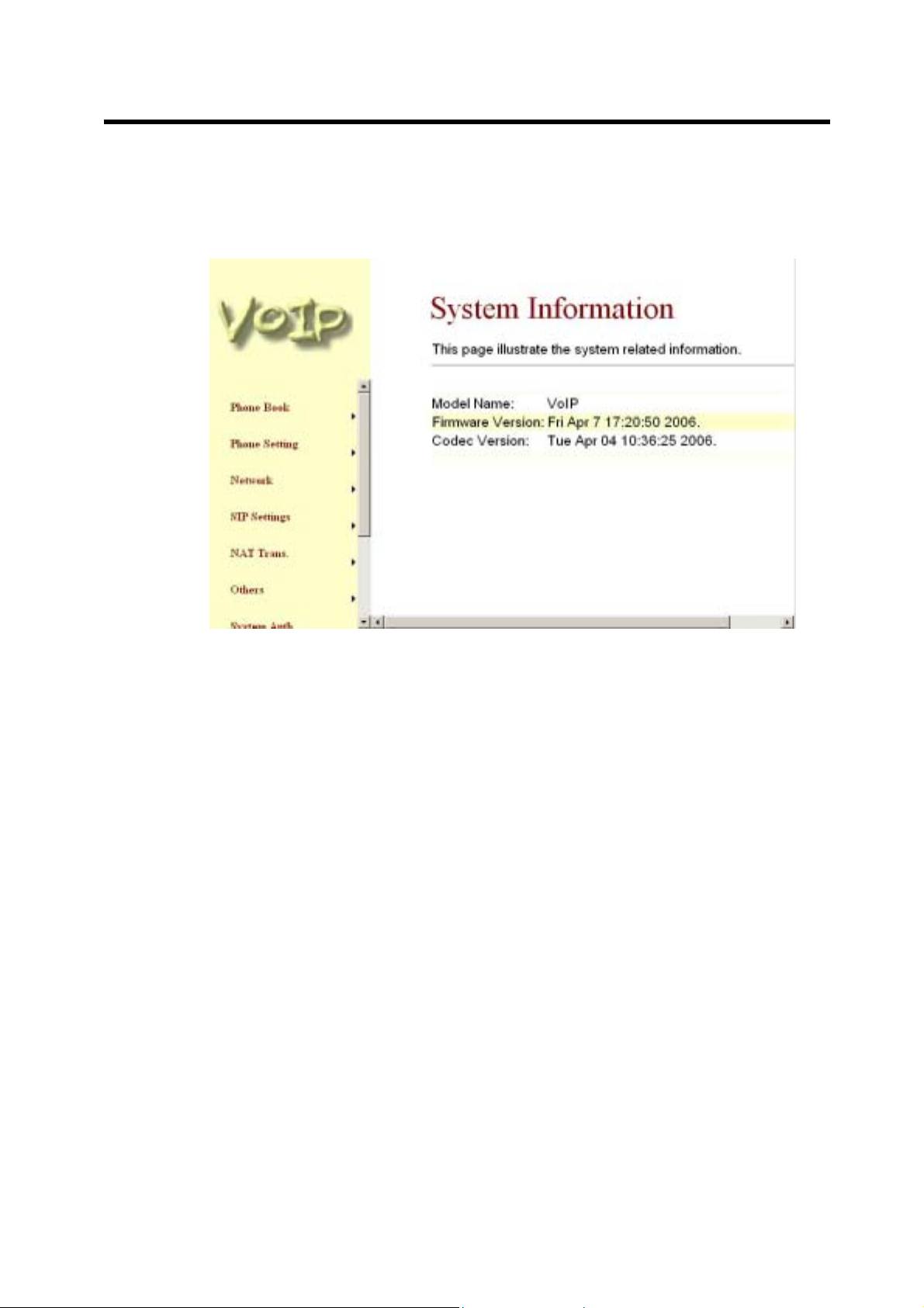
3.2 System Information for the ATA.
3.2.1 When you login the web page, you can see th e ATA current system inf orm ation like f irmware
version, company… etc in this page.
3.2.2 Also you can see the function lists in the left side. You can use mouse to click the function you
want to set up.
ATA-171/172/171P (ATA-S1/S2/P)
User’s Guide
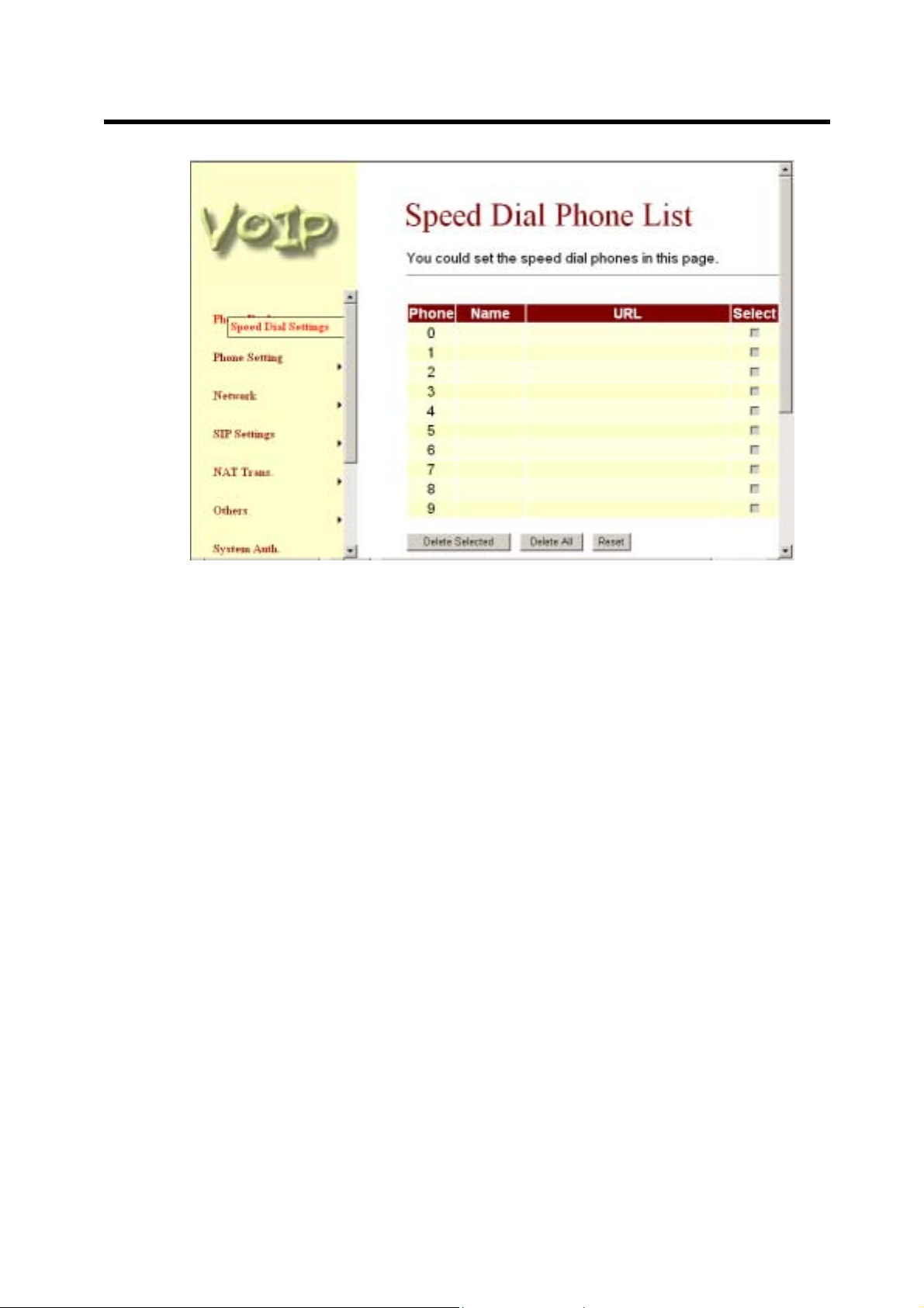
3.3 Phone Book
3.3.1 In Phone Book contains Speed Dial Settings. You can setup the Speed Dial num ber. If you
3.3.2 In Speed Dial setting function you can add/delete Speed Dial number. You can input
Figure 2. System Informa tion
want to use Speed Dial you just dial the speed dial number (from 0~9) then press “#”.
maximum 10 entries speed dial list.
-1- If you need to add a phone number into the Speed Dial list, you need to input the position,
the name, and the phone number (by URL type). When you finished a new phone list, just
click the “Add Phone” button.
-2- If you want to delete a phone number, you can select the phone number you want to
delete then click “Delete Selected” button.
-3- If you want to delete all phone numbers, you can click “Delete All” button.
5
Page 7
ATA-171/172/171P (ATA-S1/S2/P)
User’s Guide
3.4 Phone Setting
3.4.1 In Phone Setting contains Call Forward, SNTP Settings, Volume Settings, Block Setting,
3.4.2 Call For ward function: you can setup the phone num ber you want to forward in this page.
Figure 3. Speed Dial
Caller ID, Auto Dial Setting, Flash Time Setting, Call Waiting, and T.38(FAX) Setting
functions.
There are three type of For ward mode. You ca n choose Al l Forward, Bus y Forward, and No
Answer Forward b y click the icon. You can also select f o rward path to forward incom ig call to
IP or PSTN side.
-1- All For ward: All inc oming call will forward to t he number you choos ed. You can input the
name(description) and the phone num ber in URL field. If you select this f unction, then al l
the incoming call will direct forward to the speed dial number you choose.
-2- Bus y Forward: If you are on the pho ne, the new incoming c all will forward to the num ber
you choosed. You can input the name(description) and the phone number in URL field.
-3- No Ans wer Forward: : If you can not a nswer the ph one, the incom ing call wil l forward to
the number you cho osed. You can input the name(des cription) an d the phone number in
URL field. Also you have to set the Time Out time for system to start to forward the call to
the number you choosed.
-4- When you finished the setting, please click the Submit button.
-5- If there is nothing need to change, please click the Save Change Item in the left side, then
click the Save button. The change you made will save into the system and the system will
Reboot automatically.
6
Page 8

ATA-171/172/171P (ATA-S1/S2/P)
User’s Guide
Figure 4. Forward Setting
3.4.3 SNTP Setting function: you can s etup the primar y and second SNTP Server IP Address, to
get the date/tim e inform ation. Als o you c an base on your location to set t he Time Zone, an d
how long need to synchro nize again. W hen you finish ed the setting, pl ease click the Submit
button.
Figure 5. SNTP Setting
7
Page 9
ATA-171/172/171P (ATA-S1/S2/P)
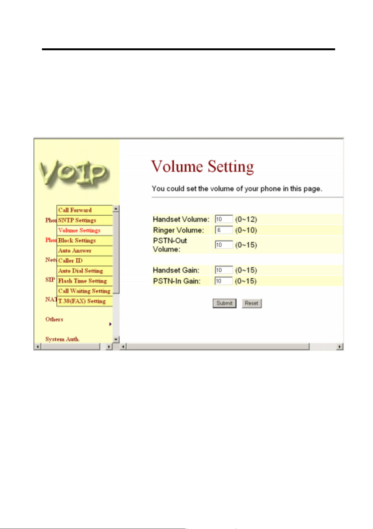
3.4.4 Volume Setting function: you can setup the Handset Volume, Ringer Volume, and the
Handset Gain. When you finished the setting, please click the Submit button.
-1- Handset Volume is to set the volume for you can hear from the handset.
-2- Ringer Volume is to set the ringer volume for you can hear.
-3- PSTN-Out Volume is is to set the volume for you can hear from the PSTN side.
-4- Handset Gain is to set the volume send out to the other side’s handset.
-5- PSTN-In Gain is to set the volume send out to the other side.
-6- When you finished the setting, please click the Submit button.
-7- If there is nothing need to change, please click the Save Change Item in the left side, then
click the Save button. The change you made will save into the system and the system will
Reboot automatically.
User’s Guide
Figure 6. Volume Setting
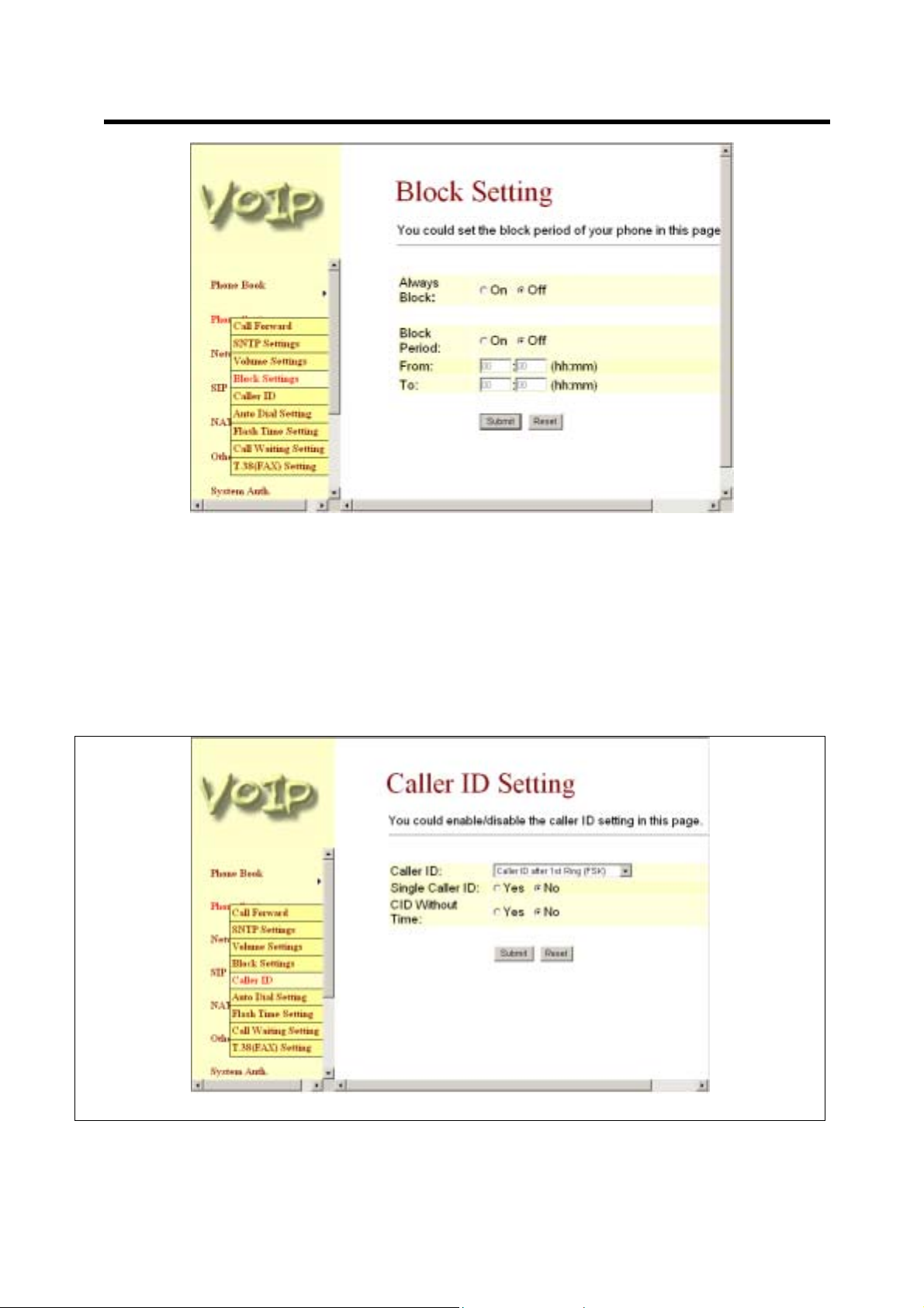
3.4.5 Block Setting function: you c an setup the Block Setting to k eep the phone slienc e. You can
choose Always Block or Block a period.
-1- Always Block: All incoming call will be blocked until dis abl e this featur e.
-2- Block Period: Set a time period and the phone will be blocked during the time period. If the
“From” time is large than the “To” time, the Block time will from Day 1 to Day 2.
-3- When you finished the setting, please click the Submit button.
-4- If there is nothing need to change, please click the Save Change Item in the left side, then
click the Save button. The change you made will save into the system and the system will
Reboot automatically.
8
Page 10
ATA-171/172/171P (ATA-S1/S2/P)
User’s Guide
Figure 7. Block Setti ng
3.4.6 Caller ID function: you can set the device to show Caller ID in your PSTN Phone or IP Phone.
-1- There are four selection of Caller ID. You need to base on your environm ent to set the
Caller ID function f or FSK or DTMF. W hen you change the setting, pleas e also double
check the PTT seting in O thers. You ne ed to choose the correct co untry code then the
Caller ID will be effect.
-2- W hen you finishe d the setti ng, please c lick the S ubmit button. If there is nothin g need to
change, please click the Save Change Item in the left side, then click the Save button. The
change you made will save into the system and the system will Reboot automatically.
Figure 8. Caller ID Setting
9
Page 11
ATA-171/172/171P (ATA-S1/S2/P)
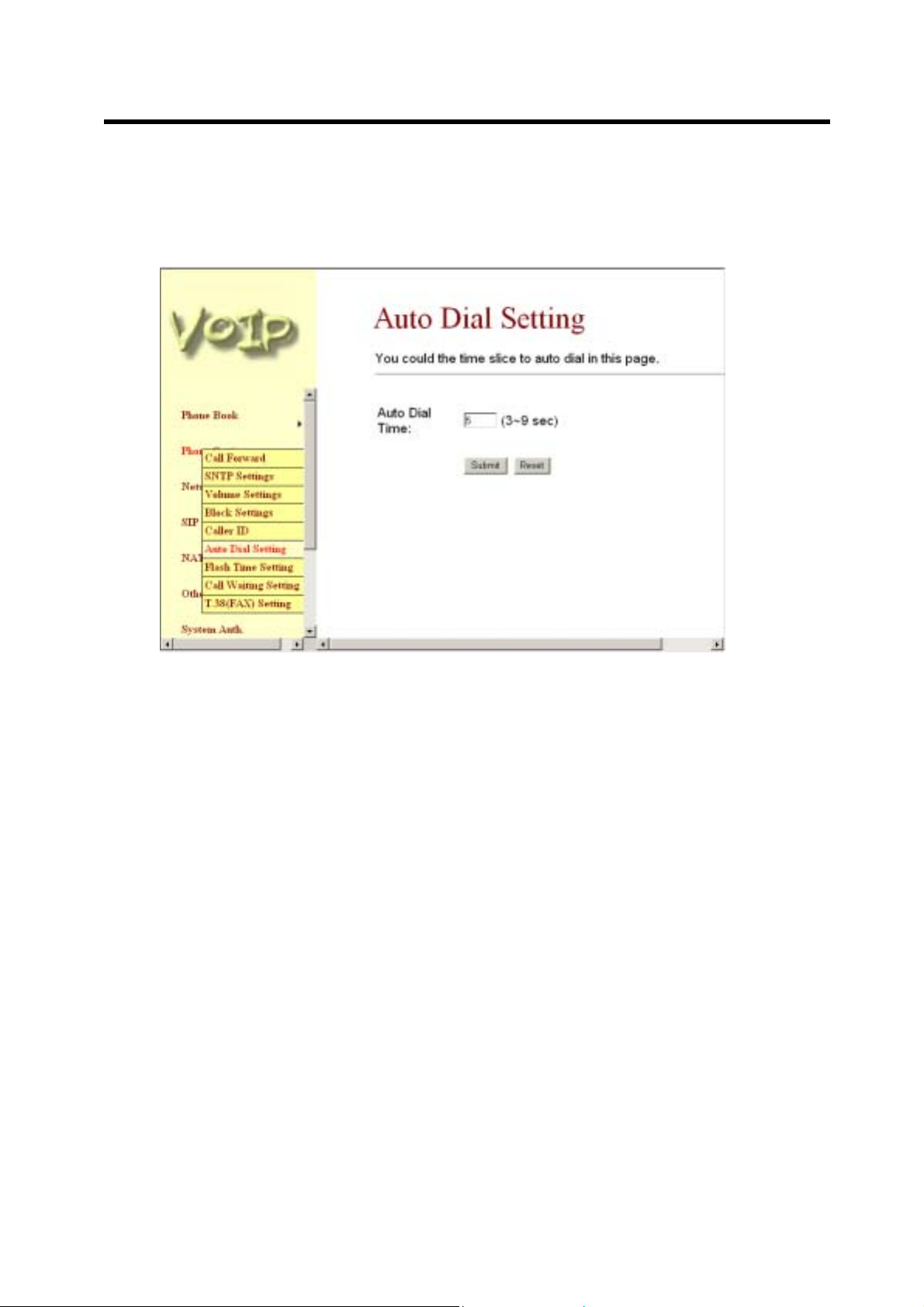
3.4.7 Auto Dial Setting functi on: This f unction is when you input the phone num ber by the k eypad
but you don’t need to pres s “#” . After time out the system will d ial d irec tl y. When you finished
the setting, please click the Submit button. If there is nothing need to change, please click the
Save Change Item in the left side, then click the Save button. The change you made will save
into the system and the system will Reboot automatically.
User’s Guide
Figure 9. Auto Dial Setting
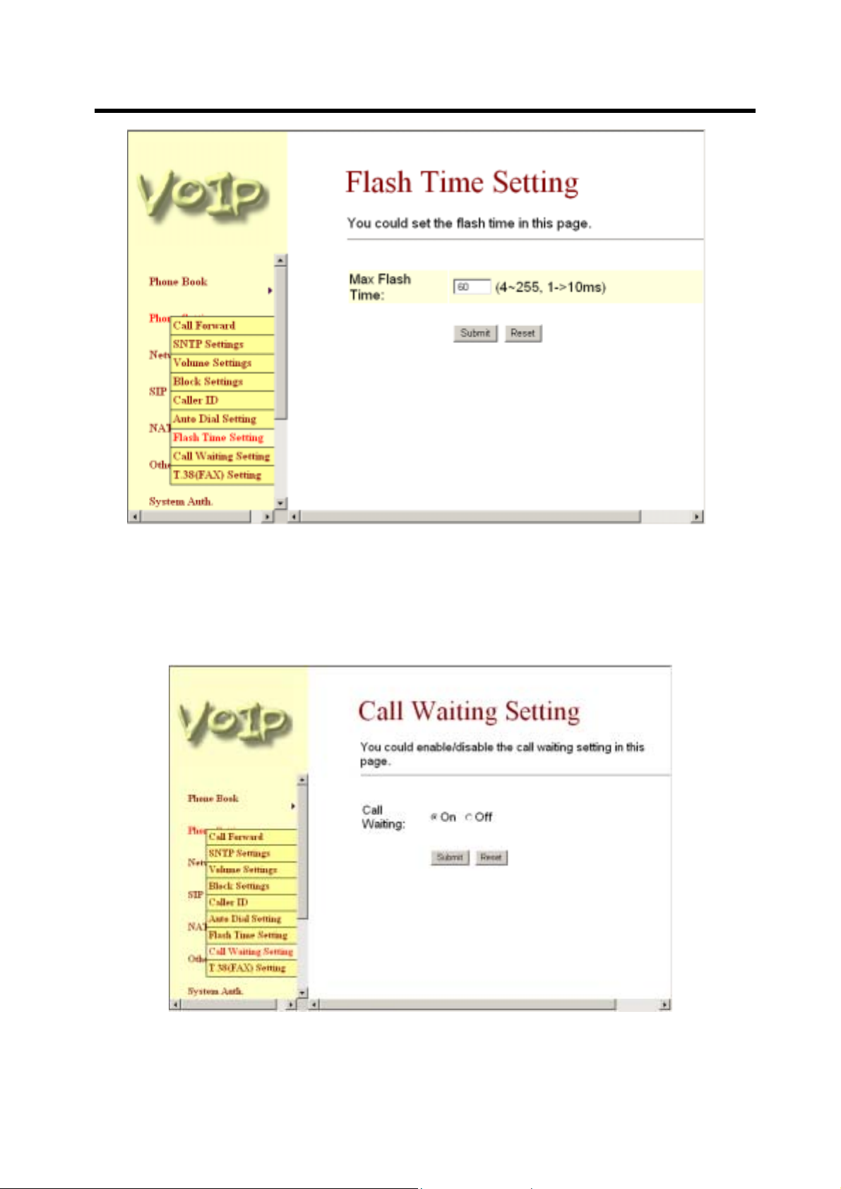
3.4.8 Flash Time Setting function: When you use the PSTN Phone and you need to press the Hook
to do the Flash (S witch to the other ph one line or HO LD), this function is for you to s et the
time you press the Hook to represent the Flash function. When you finished the setting,
please click the Submit button. If there is nothing need to change, please click the Save
Change Item in the left s ide, then c lick the Sav e button . T he change you m ade wil l save i nto
the system and the system will Reboot automatically.
10
Page 12
ATA-171/172/171P (ATA-S1/S2/P)
User’s Guide
Figure 10. Flas h Time Se tt ing
3.4.9 Cal l Waiting Setting function: You can Enable/Disable the Call Waiting function, When you
are talking with someone, there is a new incoming call, you will hear the cal l waiting tone.
When you finished the setting, please click the Subm it button. If there is nothing need to
change, please click the Save Change Item in the l eft side, then click the Save butto n. The
change you made will save into the system and the system will Reboot automatically.
Figure 11. Call Waiting Se tti ng
11
Page 13

ATA-171/172/171P (ATA-S1/S2/P)
3.4.10 T.38 Setting function: You can Enable/Disable the T.38 function. When you finished the
setting, please clic k the Submit button. If ther e is nothing need to cha nge, please click the
Save Change Item in the left side, then click the Save button. The change you made will save
into the system and the system will Reboot automatically.
User’s Guide
Figure 12. T.38 (FAX) Setting
3.5 Network
3.5.1 In Network you can check the Network s tatus, configure the NAT Settings, Bridge Sett ings,
DDNS settings and VLAN Settings.
3.5.2 Network Status: You can check the current Network setting in this page.
Figure 13. Net work Sta tus
12
Page 14

ATA-171/172/171P (ATA-S1/S2/P)
3.5.3 NAT Settings: The TA’s default setting is NAT mode. In this page you can configure th e TA
LAN and WAN port’s setting. LAN port is for you to co nnect to your PC or other Switch, a nd
the WAN port is for you to connect to the ADSL Router, Broadband Router. Also you can use
PPPoE to get the WAN IP address from your ISP.
-1- The LAN port’s default IP address is 192.168.123.1, Net Mask is 255.255.255.0., and
DHCP Server enabled. The start IP address if 150, end IP adress is 200. It is not
necessary to change the LAN settings.
-2- Yo u can connect your PC to the LAN port, set your PC as DHCP Client mode, then you
can get IP addreess from the TA.
-3- The WAN port is DHCP Client mode, You can change the setting to Fixed IP or PPPoE
Mode.
-4- If you change th e WAN port’s setting to Fix IP M ode, then you have to make sure th e IP
address. Net Mask, Gateway, and DNS setting is suitable in your current network
environment.
-5- If you change the WAN port’s setting to PPPoE Mode, you have to input a correct
username/password to get the IP address from your Internet Service Provider.
-6- When you finished the setting, please click the Submit button.
-7- If there is nothing need to change, please click the Save Change Item in the left side, then
click the Save button. The change you made will save into the system and the system will
Reboot automatically.
User’s Guide
Figure 14. NA T Se tti ngs
13
Page 15

ATA-171/172/171P (ATA-S1/S2/P)
3.5.4 Bridge Setting: If you don’t want to use the NAT Mode, then you can set the network setting in
this page.
-1- T he TCP/IP Configuration item is to setup the LAN po rt’s network enviro nment. You may
refer to your current network environment to configure the VoIP Phone properly.
-2- If you change the LAN port’s setting to F ix IP Mode, then you have to make sure the IP
address. Net Mask, Gateway, and DNS setting is suitable in your current network
environment.
-3- If you change the LAN port’s setting to DHCP Client Mode, then you have to make sure in
your current networ k env ir o nment has a DHCP server, then the TA will get the IP address
from the DHCP Server.
-4- If you change the LAN port’s setting to PPPoE Mode, you have to input a correct
username/password to get the IP address from your Internet Service Provider.
-5- If you set the Bridge On, then the t wo Fast Eth ernet ports will be trans parent. Usual ly, we
suggest you set the Bri dge Mod e is Ena ble, it will easy for you to co nnect an y one of the
port to the IP Network.
-6- When you finished the setting, please click the Submit button.
-7- If there is nothing need to change, please click the Save Change Item in the left side, then
click the Save button. The change you made will save into the system and the system will
Reboot automatically.
User’s Guide
Figure 155. Bridge Set tings
14
Page 16

ATA-171/172/171P (ATA-S1/S2/P)
3.5.5 DDNS Setting: Y ou can configure the DDNS setting in this page. You need to have the DDNS
account and input the inf ormations properly. You ca n have a DDNS accou nt with a publ ic IP
address then others can call you via the DDNS account. But now most of the VoIP
applications are work with a SIP Proxy Server. When you finished the setting, please click the
Submit button. If ther e is nothing need to chan ge, please clic k the Save Ch ange Item in the
left side, then click the Save butt on. T he ch ange you m ade will s ave into t he s ystem and the
system will Reboot automatically.
User’s Guide
Figure 16. DDNS Setting
3.5.6 VLAN Setting: You can set the VLAN setting in this page. There ar e two parts in this page.
First one is to set the pac kets relat ed to the TA, and the second parts is if you us e the VLAN
setting in the NAT Mode.
-1- There ar e two kind of destination pac kets will come from the TA’s WAN port, one kind of
packets will go to the TA, the other will go through the LAN port to the PC.
-2- VLAN Pack ets: if you enable the firs t VLAN Packets and se t the VID, User Prio rity, and
CFI, then all the incoming packets will be check with the IP Address and the VID.
-3- VID: You can follow your service provider to set your VID.
-4- User Prior ity: Defines us er priority, giving eight (2^3) prior ity levels. IEEE 8 02.1P defines
the operation for these 3 user priority bits. Usu ally this will be defined by your service
provider.
-5- CFI: Cano nical Form at Indicator is always set to zero f or Ethernet switches . CFI is us ed
for compatibility reaso n be t w een Eth ernet type network and Token Ring type network. If a
frame received at an Ethernet port has a CFI set to 1, then that frame should not be
forwarded as it is to an untagged port.
-6- When you enable the first VLAN Packets and set the VID, User Priority, and CFI, then all
the incoming packets with the TA’s IP address and the same VID will be accept by the TA.
If the incoming packets with the TA’s IP address but th e diff erent VID then t he pac kets will
be discard by the TA. The Other incoming packets with different IP address will go through
the LAN port to the PC.
-7- NAT VLAN Setting: When you set your dev ice in NAT mode, the TA can help you to filter
the wrong incom ing packets. You can separate the other device c onnectd behind th e TA
into 4 VLAN group. You can set different VID for these 4 groups. When the incoming
packets go through the TA’s WAN port then the TA will check the VID, if the packets is not
15
Page 17

ATA-171/172/171P (ATA-S1/S2/P)
going to the TA(with the T A’s IP address and the correct VID), and the VID is not these four
VID you set, then the packets will be discard by the TA.
-8- If there is nothing need to change, please click the Save Change Item in the left side, then
click the Save button. The change you made will save into the system and the system will
Reboot automatically.
User’s Guide
Figure 17. VLAN Setting
3.6 IP Settings
3.6.1 In SIP Settings you can setup the Service Domain, Port Settngs, Codec Settings, RTP
Setting, RPort Setting and Ot her Settings. If the VoIP service is provided by ISP, you need to
setup the related informations correctly then you can register to the SIP Proxy Server
correctly.
3.6.2 I In Service Domain Functi on you need to input the a ccount and the related informations in
this page, please refer to your ISP provider. You can register three SIP account in the TA. You
can dial the VoIP phone to your friends vi a first enable SIP account and rec eive the phone
from these three SIP accounts. For the second phone you can use the same way to register.
-1- First you need click Active to enable the Service Domain, then you can input the following
items:
(1-1) Display Name: you can input the name you want to displa y.
(1-2) User Name: you need to input the User Name get from your ISP.
(1-3) Register Name: you need to input the Register Name get from your ISP.
(1-4) Register Password: you need to input the Register Password get from your ISP.
(1-5) Domain Server: you need to input the Domain Server get from your ISP.
(1-6) Proxy Server: you need to input the Proxy Ser ver get from your ISP.
(1-7) Outbound Proxy: you need to input t he Outbound Prox y get from your ISP. If your
ISP does not provide the information, then you can skip this item.
(1-8) Register Period: you need to i nput the Register Peri od get from your ISP. This is
count in minute.
(1-9) You can see the R egister Status in the Status item. If the item shows “Register ed”,
then your TA is registered to the ISP, you can make a phone call direcly.
(1-10) If you have more than one SIP account, you can following the steps to register to the
other ISP.
(1-11) When you finished the setting, please click the Submit button.
16
Page 18

ATA-171/172/171P (ATA-S1/S2/P)
(1-12) If there is nothing ne ed to change, please click the Save Change Item in the le ft
side, then click the S ave button. The change you m ade will save into the system
and the system will Reboot automatically.
User’s Guide
Figure 18. Service D omain Se tting
3.6.3 Port Settings: you can set up the SIP and RTP port num ber in this page. Each ISP provid er
will have different SIP/RTPport setting, please refer to the ISP to setup the port number
correctly. When you finished the set ting, please click the Submit button. If there is nothing
need to change, please click the Save Change Item in the left side, then click the Save
button. The change you made will save into the system and the system will Reboot
automatically.
17
Page 19

ATA-171/172/171P (ATA-S1/S2/P)
User’s Guide
Figure 19. Port Setting
3.6.4 Codec Settings: you can setup the Codec priority, RTP packet length, an d VAD function in
this page. You need to follow the ISP suggestion to setup these items. When you finished the
setting, please clic k the Submit button. If ther e is nothing need to cha nge, please click the
Save Change Item in the left side, then click the Save button. The change you made will save
into the system and the system will Reboot automatically.
Figure 20. Code c S ett ing
18
Page 20

ATA-171/172/171P (ATA-S1/S2/P)
3.6.5 Codec ID Setting: Sometimes 2 VoIP device with different Codec ID will cause the
interopability issue. If you are talking with others got s ome pr oblems, you ma y ask the other
one what kind of Codec ID he use, the n you can change your Codec ID. When you finished
the setting, please click the Submit button. If there is nothing need to change, please click the
Save Change Item in the left side, then click the Save button. The change you made will save
into the system and the system will Reboot automatically.
User’s Guide
Figure 21. Codec ID Sett ing
3.6.6 DTMF Setting: you can setup the RFC2833 Out-Band DTMF, Inband DTMF and Send DTMF
SIP Info in this page. To change this setting, please following your ISP information. When you
finished the setting, please click the Submit button. If there is nothing need to change, please
click the Save Change Item in the left side, then click the Save button. The change you made
will save into the system and the system will Reboot automatically.
19
Page 21

ATA-171/172/171P (ATA-S1/S2/P)
User’s Guide
Figure 22. DTMF Setting
3.6.7 RPort Func tion: you can setup the R Port En ab le/Disable in this page. To change this setting,
please following your ISP information. When you finished the setting, pleas e c l ick the Submit
button. If there is nothin g n eed to change, please clic k the Save Change Item in t he l eft s ide,
then click the Save button. The change you made will save into the s ystem and the s ystem
will Reboot automatically.
Figure 23. RPor t Se ttin g
20
Page 22

ATA-171/172/171P (ATA-S1/S2/P)
3.6.8 Other Settings: you can se tup the Hold by RFC, Voice/SIP QoS and SIP ex pire time in this
page. To change these settings please following your ISP information. When you finished the
setting, please cl ic k the Submit button. The QoS setting is to s e t t he vo ic e packets’ priority. If
you set the value higher than 0, then the voice packets will get the higher priority to the
Internet. But the QoS f unction sti ll need to c ooperate with the other s Interne t devices . When
you finished the sett ing, please click the Submit button. If ther e is nothing need to c hange,
please click the Save Change Item in the left side, then click the Save button. The cha nge
you made will save into the system and the system will Reboot automatically.
User’s Guide
3.7 NAT Trans.
3.7.1 In NAT Trans. you can setup STUN f unction. These functions can help your ATA working
3.7.2 STUN Settin g: you can set up the STUN Ena ble/D isab le and ST UN Server IP add ress in this
Figure 24. Ot her Se t ting
properly behind NAT.
page. This function can help your TA working properl y behind N AT. To change these settings
please following your ISP information. When you finished the setting, pleas e c l ick the Submit
button. If there is nothin g n eed to change, please clic k the Save Change Item in t he l eft s ide,
then click the Save button. The change you made will save into the s ystem and the s ystem
will Reboot automatically.
21
Page 23

ATA-171/172/171P (ATA-S1/S2/P)
User’s Guide
3.8 Others
Figure 205. STUN Setti ng
3.8.1 In Others you can setup Auto Conf ig, PTT Setting and ICMP Setting f unction. The function
can configure your VoIP Phone automatically.
3.8.2 Auto Config: you can se tup the Auto Conf igur ation Enable/Dis abl e and au to conf igurati on b y
FTP or TFTP. You need to select the way to do the Auto Config urationand set t he Server IP
address in this page. This function can automatically download the configure file to setup your
TA.
3.8.3 When you finished the setting, please click the Submit button.
3.8.4 If there is nothing need to change, ple ase click the Save Change Item in t he left side, then
click the Save button . The change you made will sa ve into the system and the s ystem will
Reboot automatically.
22
Page 24

ATA-171/172/171P (ATA-S1/S2/P)
User’s Guide
Figure 216. Auto Configurati on Setting
3.8.5 ICMP Setting: you can setup the ICM P echo Enable/Disab le in this page. This f unction can
disable echo when someone ping this device, it can avoid haker try to attack the device.
When you finished the setting, please click the Subm it button. If there is nothing need to
change, please click the Save Change Item in the l eft side, then click the Save butto n. The
change you made will save into the system and the system will Reboot automatically.
Figure 227. Auto Configurati on Setting
23
Page 25

ATA-171/172/171P (ATA-S1/S2/P)
User’s Guide
Figure 238. ICMP Setting
3.8.6 PTT Setting: you can setup the PTT in this page. When you are using different countr y’s
PSTN Phone, you have to set the country’s setting to meet the requirement. When you
finished the setting, please click the Submit button. (For ATA-171P only)
Figure 249. PTT Setting
24
Page 26

3.9 System Auth.
3.9.1 In System Authorit y you can chan ge your logi n name and passwor d. When you finished the
ATA-171/172/171P (ATA-S1/S2/P)
User’s Guide
setting, please clic k the Submit button. If ther e is nothing need to cha nge, please click the
Save Change Item in the left side, then click the Save button. The change you made will save
into the system and the system will Reboot automatically.
3.10 Save Change
3.10.1 In Save Change you can save the chan ges you have done . If you want to use ne w setting in
Figure 30. System Authority
the ATA, You have to click the Save button. After you click the Save button, the ATA will
automatically restart and the new setting will effect.
25
Page 27

ATA-171/172/171P (ATA-S1/S2/P)
User’s Guide
3.11 Update
Figure 31. Sa ve Cha nge
3.11.1 In Update you can update the ATA’s firmware to the new one or do the fac tory reset to let the
ATA back to default setting.
3.11.2 In New Firmware function you can update new firmware via HTTP in this page. You can
ugrade the firmware by the following steps:
-1- Select the firmware code type, Risc or DSP code.
-2- Click the “Browse” button in the right side of the File Loc ation or you can type the correct
path and the filename in File Location blank.
-3- Select the correct file you want to download to the ATA then click the Update button.
-4- After finished the update firmware process, the system will Reboot automatically.
26
Page 28

ATA-171/172/171P (ATA-S1/S2/P)
User’s Guide
Figure 32. U pdate Fi rmwa re
3.11.3 In Default Setting you can r estor e the TA to factory default in this page. You can just click the
Restore button, then the TA will restore to default and automatically restart again. The Default
Setting will be NAT Mode, WAN port is DHCP Client Mode, LAN port is Fixed IP Mode and the
IP Address is 192.168.123.1.
27
Page 29

ATA-171/172/171P (ATA-S1/S2/P)
User’s Guide
3.12 Reboot
Figure 33. Restore Default Setting
3.12.1 Reboot function you ca n re s tart the ATA. If you want to restart the ATA, you can just click the
Reboot button, then the ATA will automatically.
Figure 34. Reboot System
28
Page 30

ATA-171/172/171P (ATA-S1/S2/P)
4 Setup the ATA by using Console (Hyper Terminal)
4.1 Configure the COM port
First Open the hyper terminal window, select the connection by the COM port, and then click the “Setting”
button.
User’s Guide
Figure 25. Cons ole Se tting -1
Set the COM port’s setting as following setting. Then click OK.
Figure 26. Cons ole Se tting -2
29
Page 31

ATA-171/172/171P (ATA-S1/S2/P)
4.2 Login into the ATA
After finished the setting, click the “Connect” button (looks like a telephone icon). Then the hyper terminal is
ready to connect to the ATA. Press “Enter” and the hyper terminal will show the “Login: “. Input “root” and
press the “Enter” button. Then hyper terminal will show the “Password: “. Input “test” and press the “Enter”
button. Now you already login the ATA. Please follow the CLI command list to configure the ATA with proper
instruction and value.
User’s Guide
Figure 27. Cons ole Scre en
30
Page 32

4.3 Using CLI command to configure the ATA
4.3.1 CLI command list as below:
Index Command Description
1 ? Show CLI Command
2 arp ARP Configuration
3 ipconfig Interface Configuration
4 save Save to flash
5 reboot Reboot
6 exit Exit
7 debugmode Enter Debug Mode
8 update Update Flash Code/RAM
9 auth Change User Name and Password
10 nat NAT Configuration
11 dns DNS Configuration
12 ping ping [-lN] [IP-addr|host-name]
13 sip SIP Configuartion
14 ddns DDNS Configuartion
15 sntp SNTP Configuartion
16 vlan VLAN Configuartion
17 time Get System Time
18 mactab Show MAC Learning Table
19 dump Read/Write Memory
20 book Edit phone book
21 reload Reload Factory Setting
22 watchdog WatchDog Function
23 phone Phone Setting
24 weblogo Change Web's logo
25 dsp Show dsp type
26 addport Add Nat Port Mapping
27 cid Select slic Cid
28 slic read or write slic registers
29 ver Firmware Version
-1- “?” function is to show CLI command list in the screen.
-2- arp function
Index Command Description
1 ? Show 'arp' Option
2 -a Show ARP Table
3 -d Delete ARP Table
4 -s Set Static ARP Table
5 (null) Show ARP Table
-3- ipconfig function
Index Command Description
1 ? Show 'ipconfig' Option
2 -if0 Interface 0
3 -if1 Interface 1
4 -if2 Interface 2
5 -h Set Host Name
6 -a Set ARP Cache Expire
7 -r Restore Current Setting
8 (null) Show IP Setting
(3-1) ipconfig –ifN function Æ N is 0, 1, 2
Index Command Description
ATA-171/172/171P (ATA-S1/S2/P)
User’s Guide
31
Page 33

ATA-171/172/171P (ATA-S1/S2/P)
1 ? Show 'ipconfig -ifN' Option
2 -t Set Host Type
3 -m Set MAC Address
4 -i Set IP Address
5 -nm Set Net Mask
6 -g Set Gateway
7 -dns0 Set Primary DNS server
8 -dns1 Set Secondary DNS server
9 -dr Set Default Route
10 -nat Set NAT
11 on Enable Interface
12 off Disable Interface
13 -dhcps DHCP Server Setting
14 -ddns Set DDNS
15 -bridge Set Bridge
16 -dev0 Set Device 0 Setting
17 -dev1 Set Device 1 Setting
18 -dev2 Set Device 2 Setting
19 (null) Show Interface Setting
-4- save function
Index Command Description
1 ? Show 'save' Option
2 -book Save phone book
3 -sys Save system setting
-5- reboot function is to restart the system.
-6- exit function is to exit the CLI.
-7- debugmode function is to enter the debugmode.
-8- update function
Index Command Description
1 ? Show 'update' Option
2 -os Update OSImage(IP filename)
3 -dsp Update DSP Image(IP filename)
4 -all Update All Image(IP filename)
5 -server Update Server (IP filename length)
6 -pcm PCM(IP filename)
-alaw alaw (IP filename)
-ulaw ulaw (IP filename)
-g729 g729 (IP filename)
-g723 g723 (IP filename)
-g726.16 g726.16 (IP filename)
-g726.24 g726.24 (IP filename)
-g726.32 g726.32 (IP filename)
-g726.40 g726.40 (IP filename)
IP is the TFTP server ’s IP address, a nd the filen ame is the image you want to downlo ad into the
system.
-9- auth function
Index Command Description
1 ? Show 'auth' Option
2 -admin Change Administrator user name/password
3 -sys0 Change System user0 user name/password
User’s Guide
32
Page 34

ATA-171/172/171P (ATA-S1/S2/P)
4 -sys1 Change System user1 user name/password
5 -sys2 Change System user2 user name/password
6 -sys3 Change System user3 user name/password
7 -sys4 Change System user4 user name/password
8 -norm0 Change Normal user0 user name/password
9 -norm1 Change Normal user1 user name/password
10 -norm2 Change Normal user2 user name/password
11 -norm3 Change Normal user3 user name/password
12 -norm4 Change Normal user4 user name/password
13 -ppp Chan ge PPP user nam e/pas s word
14 (null) Show auth Setting
In each item includes
Index Command Description
1 ? Show 'auth' Option
2 -user Change User Name.'auth -sys3 -user xxx '
3 -pass Change Password. 'auth -sys3 -pass xxx xxx'
4 (null) Show auth's System/PPP Setting
If you want to change the password, you need to type the password twice in the CLI.
-10- nat function
Index Command Description
1 ? Show 'nat' Option
2 -vs Set 'nat -vs' Option
3 -dmz Set 'nat -dmz' Option
4 (null) Show NAT Setting
In DMZ item includes
Index Command Description
1 ? Show 'nat -dmz' Option
2 on EnableDMZ
3 off EnableDMZ
4 -ip Set DMZ IP address
5 (null) Show DMZ Setting
-11- dns function
Index Command Description
1 ? Show 'dns' Option
2 -q DNS query. dns -q domain-name
3 (null) Show DNS Table
-12- ping function
Index Command Description
1 ? Show 'ping' Option
2 -l ping [-l N] [IP-addr|host-name]
3 (null) ping [IP-addr|host-name]
User’s Guide
33
Page 35

ATA-171/172/171P (ATA-S1/S2/P)
-13- sip function
Index Command Description
1 ? Show 'sip' Option
2 -proxy0 sip -proxy0
3 -proxy1 sip -proxy1
4 -proxy2 sip -proxy2
5 -upnp sip -upnp on/off/show
6 -exts sip -exts sip upnp external-port
7 -extr sip -extr rtp upnp external-port
8 -sipp sip udp port
9 -rtpp sip rtp port
10 -stun sip -stun on/off
11 -rport sip -rport on/off
12 -sserver sip -sserver stun-server
13 -out sip -out outbound-proxy
14 -dump sip –dump
15 -log sip -log on/off
16 -drtp sip -drtp 0/1/2
17 -rtpnc sip -rtpnc on/off
18 -wanip sip –wanip
19 -nattype sip –nattype
20 -hbyrfc sip –hbyrfc
21 -dereg sip -dereg
22 -restart sip -restart
23 -jbt sip -jitter buffer Threshold
24 (null) Show SIP Setting
-14- ddns function
Index Command Description
1 ? Show 'ddns' Option
2 -type Set DDNS Type
3 -host Set Host Name
4 -wild Set Wild Card Mode
5 -mx Set Mail Exchanger
6 -backmx Set Mail Exc han ger Mode
7 -offline Set Offline Mode
8 -user Set Login User Name
9 -pass Set Login Password
10 (null) Show DDNS Setting
-15- sntp function
Index Command Description
1 ? Show 'sntp' Option
2 -on Enable SNTP Client
3 -off Disable SNTP Client
4 -ip1 Set SNTP Server1 IP
5 -ip2 Set SNTP Server2 IP
6 -mode Set SNT P Client Mode
7 -zone Set GMT Time Zone: [+|-][hour]:[min]
8 -adjust Set Adjustment Time: [second]
9 (null) Show SNTP Setting
User’s Guide
34
Page 36

ATA-171/172/171P (ATA-S1/S2/P)
-16- vlan function
Index Command Description
1 ? Show 'vlan' Option
2 -tx Tx Vlan setting
3 -rx Rx Vlan setting
4 (null) Show Vlan Setting
-17- time function
Index Command Description
1 ? Show 'Time' Option
2 -t Modify Time: hour:min:sec
3 -d Modify date: year:mon:date
4 (null) Show Data & Time
-18- mactab function is to show MAC learning table.
-19- dump function
Index Command Description
1 ? Show 'dump' Option
2 -r dump -r XXXXxxxx
3 -w dump -w XXXXxxxx XX
-20- book function
Index Command Description
1 ? Show 'book' Option
2 -a Show answer list
3 -c Show call list
4 -s speed dial
5 -p phone book
-21- reload function is to Reload Factor y Setting, p lease make sure you want to do the f actor y
reset.
-22- watchdog function
Index Command Description
1 ? Show 'WatchDog' Option
2 on Enable WatchDog
3 off Disable WatchDog
4 (null) Show WatchDog Setting
-23- phone function
Index Command Description
1 ? Show 'phone' Option
2 -autoanswer phone auto answer
3 -vol Volume setting
4 -block Block Incoming call
5 -ring Set Melody Ringer
6 -forward Auto-forward Incall to Phone[0-9] in Book
7 (null) Show Phone Setting
User’s Guide
35
Page 37

ATA-171/172/171P (ATA-S1/S2/P)
-24- weblogo function
Index Command Description
1 ? Show 'weblogo' Option
2 -on Vender Logo
3 -off Default Logo
4 (null) Show weblogo Setting
-25- dsp function is to show dsp code type.
-26- addport function is to add Nat Port Mapping
-27- cid function
Index Command Description
1 ? Show 'cid' Option
2 -off Disable Slic Cid signal
3 -1 Tx FSK after 1st Ring
4 -2 Tx FSK before 1st Ring
5 -3 Tx DTMF before 1st Ring
6 -4 Tx FSK with Line reversal before 1st Ring
7 -5 Tx DTMF with Line reversal before 1st Ring
8 -time FSK cid with time message
9 -single Single type FSK CID
10 (null) Show Cid Option
-28- slic function
Index Command Description
1 ? Show 'slic' Option
2 -ring Issue Ring signal
3 -r read slic addr
4 -w write slic addr
5 -a read all slic reg
6 (null) Show slic register
-29- ver function is to show Firmware Version.
User’s Guide
36
Page 38

5 How to make a phone call
When your ATA is configured properl y, you can m ake a phone call to your fr iend in the same Service
provider.
If you want to make a phone call, you can dial the phone number and pres s “#” button t o s tart to dial the
phone number.
The ATA also provides some functions that list as below:
1. Call Waiting: When a new call is co ming while you are talk ing, you can push the Fl ash button to
switch to the new call. You c an push the Flash butt on to switc h bet ween the t wo calls .
2. Call Hold: You can push the Hold key to hold the current call for a while, then push Hold key again to
keep talking.
3. 3-way conference: If you want to m ake a 3-way conferenc e call, you can m ake a phone call to the
first phone num ber. After the call is established, pus h the Flash butt on then you can hear the Dial
tone, then mak e a phone call to the sec ond phone number. When the secon d call is established,
press the Flash button again.
ATA-171/172/171P (ATA-S1/S2/P)
User’s Guide
37
 Loading...