

Page 1

ATA-151/152
ATA-151/152
Quick Guide
Quick Guide
Page 2

1. Copyright declaration
The copyright of the content which been
mentioned in this manual is owned by Welltech
computer Co., Ltd.
The copyright of brand and mark which been
mentioned is belong to its own company.
2005 Copyright Welltech computer Co., Ltd.
2. Before installation
Please check the following items before the
installation, that can avoid some unknown
problems during installation:
1.Preparing the following equipment for
installation:
a. A pc with network connection.
b. Ethernet RJ-45 cable
c. Phone and RJ-11 cable
2.Prepareing 1 of the following Network connection:
a. Static IP: a valid fixed IP address
b. DHCP: Make sure the DHCP server is
available.
c. PPPoE: Prepare a valid username and
password, further more,
confirm the XDSL modem is
functional.
3.Power
Make sure the power supply is adaptable.
3. Check the accessories
Please check the accessories after you open the
packing, there should have the parts as list in
below:
a. ATA mainframe X 1
b. 1M Ethernet RJ-45 cable with X 1
c. DC 12V, 1A Power adapter X 1
d. Document CD X 1, there is User guide and Quick
guide is embedded.
4
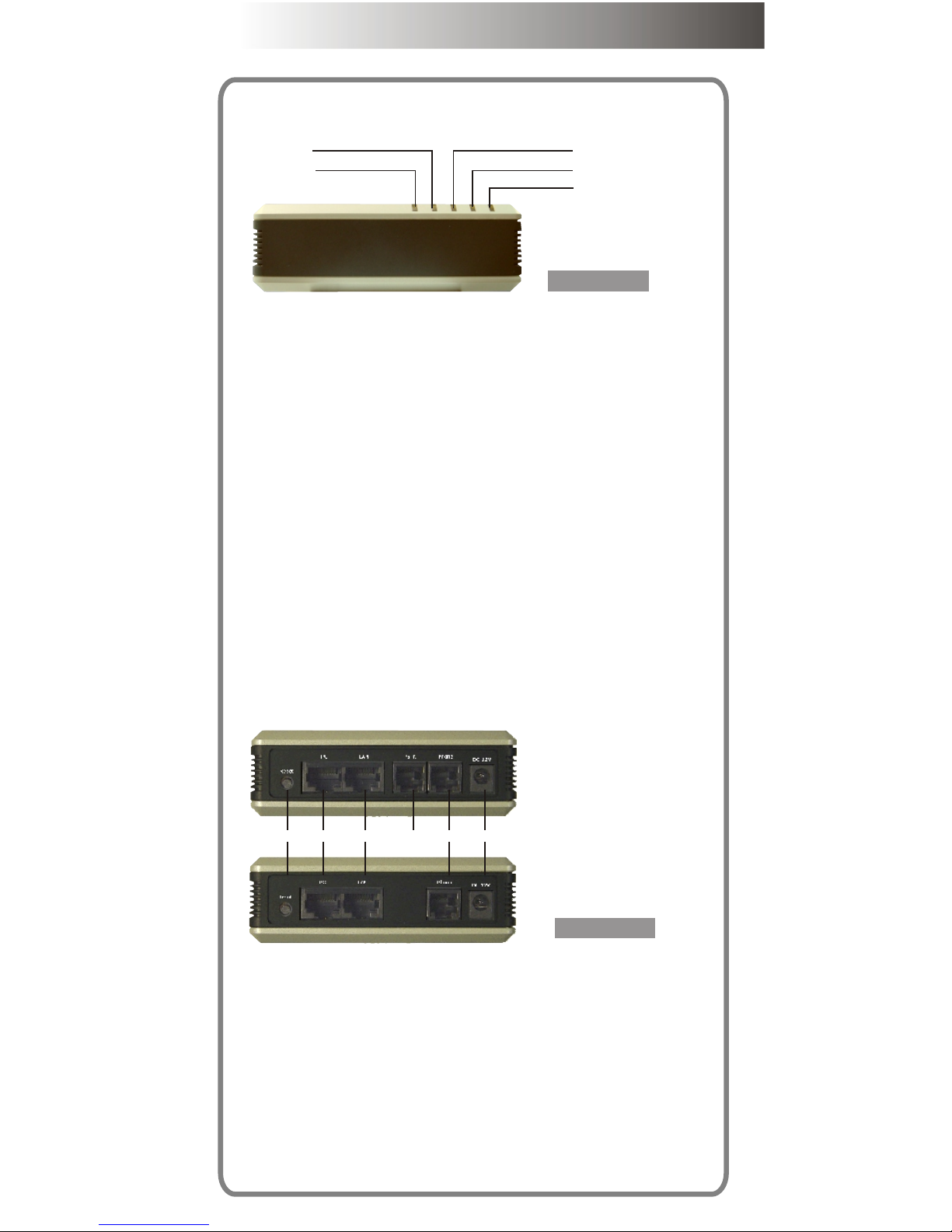
4.Physical Interface
4.1 Indicator
4.2 Connection port
6.For backing to factory default if this button is
pressed over 5 seconds.
7.For PC to connect to network with a RJ-45
ethernet cable that via ATA-151/152.
8. For ATA-151/152 to connect to a private network
or internet with a RJ-45 ethernet cable.
9. For connecting to PSTN(Fixed line) with a RJ-11
cable as backup if network failed.
10. For connecting to a analog telephone with a RJ-
11 cable.
11. Connect power adapter here.
1.PC connecting indicator
Light on: PC is connected
Light off: PC is disconnected
2.Network connecting indicator
Light on: Network is standby
Light off: Network is failed
Light flash: Data is transmitting
3.Phone active indicator
Light on: Phone is picked up
Light off: Phone is standby
Light flash: Incoming call
4.Registration indicator
Light on: Register is successful
Light flash: Register is failed
5.Power indicator
Light on: Power is ok
Light off: Power is failed
t
atu
S
s
P
h eon
L
AN
C
P
w
e
r
Po
ATA-151
1
2
6
7 8
9
1
0
11
ATA-151
ATA-152
Page 3
4
4.Physical Interface
4.1 Indicator
4.2 Connection port
6.For backing to factory default if this button is
pressed over 5 seconds.
7.For PC to connect to network with a RJ-45
ethernet cable that via ATA-151/152.
8. For ATA-151/152 to connect to a private network
or internet with a RJ-45 ethernet cable.
9. For connecting to PSTN(Fixed line) with a RJ-11
cable as backup if network failed.
10. For connecting to a analog telephone with a RJ-
11 cable.
11. Connect power adapter here.
1.PC connecting indicator
Light on: PC is connected
Light off: PC is disconnected
2.Network connecting indicator
Light on: Network is standby
Light off: Network is failed
Light flash: Data is transmitting
3.Phone active indicator
Light on: Phone is picked up
Light off: Phone is standby
Light flash: Incoming call
4.Registration indicator
Light on: Register is successful
Light flash: Register is failed
5.Power indicator
Light on: Power is ok
Light off: Power is failed
tt
uS a
s
he
P o
n
L
A
N
C
P
w
e
rP
o
ATA-151
Figure 1.
1
2
3
4
5
Figure 2.
6
7 8
9
1
0
11
ATA-151
ATA-152
Page 4
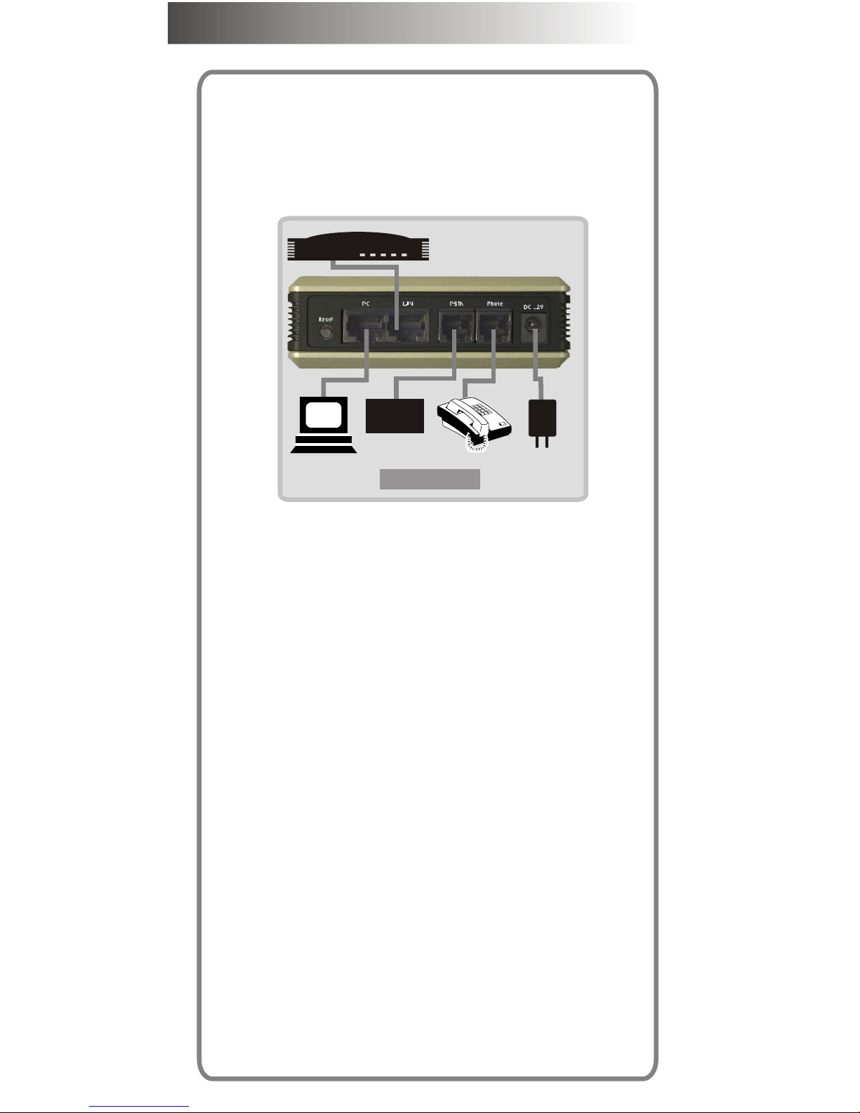
5. Start to installation
The following will show you how to install and
configure the ATA-151/152 step by step.
Scenario 1. XDSL connection
Connect to XDXL modem directly.
Please refer the figure 3 to install.
Step 1.
Plug RJ-45 cable for connecting from LAN port to
XDSL modem..
Step 2.
Plug RJ-11 cable for connecting to a valid analog
phone.
Step 3.
Plug RJ-11 cable CO PSTN line into PSTN port.
Step 4.
Plug the power adapter with valid power into DC 12V
port for getting adaptable power to ATA.
Step 5.
Now, please check the LED indicator for make sure if
the LED status as the following:
1. Power: ON
2. Status: Blinking
3. Phone: It should be off, if the handset of
analog phone is not picked up
4. LAN: ON
5. PC: ON
Step 6.
Plug RJ-45 cable for connecting from PC port.
Note:
Please disable the fuirewall to prevent some
error that during configuration if there is any
firewall software is installed. You can restart
the firewall after the configuration is finished.
PSTN
CO line
XDSL Modem
PC
Figure 3.
6
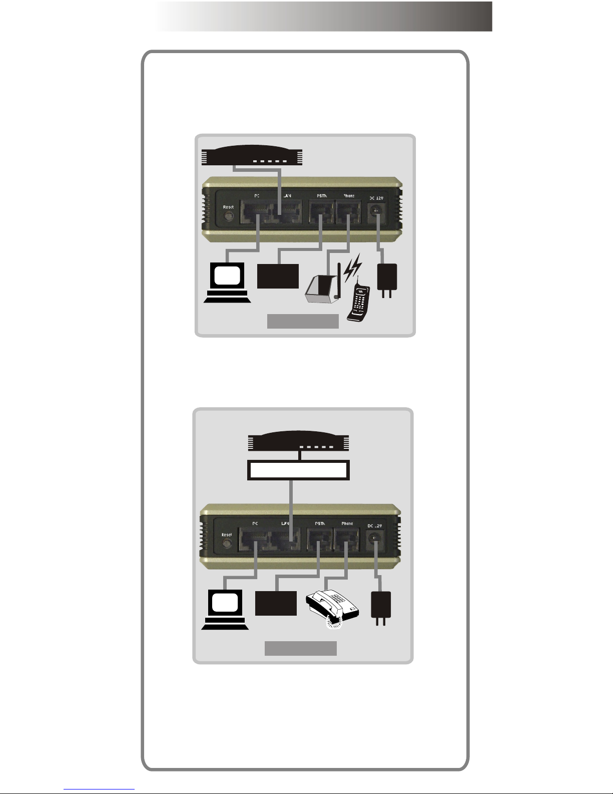
Scenario 1.1. Cordless connection
Also you can connect a cordless phone to ATA for
instead of a cord phone as figure 5 if you don't
want to be limited by a annoying cord, and there is
no any special setting.
Scenario 2 HUB connection
Connect to HUB or switch HUB directly.
Please refer the figure 6 to install.
All of step of setup is same with scenario 1.
PSTN
CO line
XDSL Modem
PC
Figure 5.
7
PSTN
CO line
XDSL Modem
PC
Figure 6.
HUB
Page 5
Scenario 1.1. Cordless connection
Also you can connect a cordless phone to ATA for
instead of a cord phone as figure 5 if you don't
want to be limited by a annoying cord, and there is
no any special setting.
Scenario 2 HUB connection
Connect to HUB or switch HUB directly.
Please refer the figure 6 to install.
All of step of setup is same with scenario 1.
PSTN
CO line
XDSL Modem
PC
Figure 5.
7
PSTN
CO line
XDSL Modem
PC
Figure 6.
HUB
Page 6

7. Configuration
Section 1. Configure your PC
Step 1.
Double click "My network places "
Step 2.
Click "View network connections"
Step 3.
Right -click "Local Area connection" then select
"Properties"
9
Step 4.
Step 5.
Step 6. Run Iexplorer
Step 7. Input 192.168.123.123
Click "Internet Protocol (TCP/IP)"
Click Obtained an IP automatically
10
Page 7

Step 4.
Step 5.
Step 6. Run Iexplorer
Step 7. Input 192.168.123.123
Click "Internet Protocol (TCP/IP)"
Click Obtained an IP automatically
10
Page 8

Step 8. Please input "root" as a username then
enter, then you will login into the configuration WEB
page.
Step 9. Click "Installation wizard"
Step 10. Click next which on right-button of the
screen.
Step 11.There are 3 options for you to select.
1. Static IP - Please goto step 12.
2. DHCP - Please goto step 14.
3. PPPoE - Please goto step 15.
Step 12. The first option is for you to configure a
valid static IP.
11
Step 13. You can fill the IP address, Subnet mask
and gateway IP here. Please goto step 18 after this
step.
Step 14.DHCP mode is for you to configure the ATA
if you used dynamic IP already, the option will be
better for you. Please goto step 18 after you finish
this step.
Step 15.PPPoE mode is another option if you had
got a account and password from your ISP.
12
Page 9

Step 13. You can fill the IP address, Subnet mask
and gateway IP here. Please goto step 18 after this
step.
Step 14.DHCP mode is for you to configure the ATA
if you used dynamic IP already, the option will be
better for you. Please goto step 18 after you finish
this step.
Step 15.PPPoE mode is another option if you had
got a account and password from your ISP.
12
Page 10

Step 16. Please input the account and password
here which given by your ISP.
Step 17. Click "Next"
Step 18. There are 2 of operation
mode for you to choose, one "Proxy
mode", another is "P2P mode".
You can choose "Proxy mode" if you
can get service from a voice service
provider or there is a valid service
platform in your place already,
otherwise we recommend you to
choose "P2P" mode.
Follow the steps in below if the "Proxy mode"
is selected.
Step 19. To fill the Primary Proxy Address with a
valid IP address which given by your provider.
Step 20. You can ignore to fill the secondary
proxy address if it is not provided.
Step 21. The Outbound proxy is same with last
step, unless the provider has offered such
configuration, otherwise you can ignore it directly.
Step 22. Input the phone number, registration
account and password which issued by your
provider.
Step 23. Click "OK
Step 24. Normally. all of the port configuration
can be ignored if the provider has not specified.
Please goto step
Follow the steps if the "P2P mode" is selected.
Notice: Basically, in proxy mode the provider will
record the number of ATA into a database after the
registration is successful. So you can pick-up the
phone then dial a number directly. But there is no
13
any provider if "P2P mode" is selected, so you need
to configure The number which you will dial in the
future by manual.
Step 25. Please configure the number which you
will dial via the following steps.
Step 26.Click the Arrow beside "Advanced
Configuration" then click "Number Configuration".
Step 27. You can find the "Phone book"
configuration on major-screen.
Step 28. The Phone Book is for you to define the
number for your called party.
Example:
If You want to define a number for your friend who
had a same product.
1. Input the digits as a index, it can be defined by
yourself.
2. Give a name as a note for easy
to recognize.
3. Define a "e.164 number" for
the called party that for you
14
Page 11

any provider if "P2P mode" is selected, so you need
to configure The number which you will dial in the
future by manual.
Step 25. Please configure the number which you
will dial via the following steps.
Step 26.Click the Arrow beside "Advanced
Configuration" then click "Number Configuration".
Step 27. You can find the "Phone book"
configuration on major-screen.
Step 28. The Phone Book is for you to define the
number for your called party.
Example:
If You want to define a number for your friend who
had a same product.
1. Input the digits as a index, it can be defined by
yourself.
2. Give a name as a note for easy
to recognize.
3. Define a "e.164 number" for
the called party that for you
14
Page 12

can dial the number to talk.
4. Input the IP address of the called party.
5. No need to configure the port setting unless
you know how to define.
6. Click "Add" for adding a record into phone
book.
7. You can configure other information as the
above steps if there is not only one called party.
Step 29. Click "Reboot”
Step 30. Click "Reboot".
So far the basic configuration is
finished, please wait 30 seconds
until the ATA rebooting complete.
15
ATA-151/152
快速安裝
Page 13

ATA-151/152
快速安裝
Page 14

1. 版權宣告
The copyright of the content which been
mentioned in this manual is owned by Welltech
computer Co., Ltd.
The copyright of brand and mark which been
mentioned is belong to its own company.
2005 Copyright Welltech computer Co., Ltd.
2. 安裝之前
在您開始安裝之前,請先檢查下列所需之環境是否準備
齊全,以避免一些不明原因所導致的錯誤發生:
1. 請準備下列設備:
a. 一台具備網路連線的PC
b. 一條乙太網路RJ-45連接線
c. 一條RJ-11電話線
2.Prepareing 1 of the following Network connection:
a. Static IP: a valid fixed IP address
b. DHCP: Make sure the DHCP server is
available.
c. PPPoE: Prepare a valid username and
password, further more,
confirm the XDSL modem is
functional.
3.Power
Make sur the power supply is adaptable.
3. Check the accessories
Please check the accessories after you open the
packing, there should have the parts as list in
below:
a. ATA mainframe X 1
b. 1M Ethernet RJ-45 cable with X 1
c. DC 12V, 1A Power adapter X 1
d. Document CD X 1, there is User guide and Quick
guide is embedded.
4
4.Physical Interface
4.1 Indicator
4.2 Connection port
6.For backing to factory default if this button is
pressed over 5 seconds.
7.For PC to connect to network with a RJ-45
ethernet cable that via ATA-151/152.
8. For ATA-151/152 to connect to a private network
or internet with a RJ-45 ethernet cable.
9. For connecting to PSTN(Fixed line) with a RJ-11
cable as backup if network failed.
10. For connecting to a analog telephone with a RJ-
11 cable.
11. Connect power adapter here.
1.PC connecting indicator
Light on: PC is connected
Light off: PC is disconnected
2.Network connecting indicator
Light on: Network is standby
Light off: Network is failed
Light flash: Data is transmitting
3.Phone active indicator
Light on: Phone is picked up
Light off: Phone is standby
Light flash: Incoming call
4.Registration indicator
Light on: Register is successful
Light flash: Register is failed
5.Power indicator
Light on: Power is ok
Light off: Power is failed
t
atu
S
s
P
h eon
L
AN
C
P
w
e
r
Po
ATA-151
1
2
6
7 8
9
1
0
11
ATA-151
ATA-152
Page 15

4
4.Physical Interface
4.1 Indicator
4.2 Connection port
6.For backing to factory default if this button is
pressed over 5 seconds.
7.For PC to connect to network with a RJ-45
ethernet cable that via ATA-151/152.
8. For ATA-151/152 to connect to a private network
or internet with a RJ-45 ethernet cable.
9. For connecting to PSTN(Fixed line) with a RJ-11
cable as backup if network failed.
10. For connecting to a analog telephone with a RJ-
11 cable.
11. Connect power adapter here.
1.PC connecting indicator
Light on: PC is connected
Light off: PC is disconnected
2.Network connecting indicator
Light on: Network is standby
Light off: Network is failed
Light flash: Data is transmitting
3.Phone active indicator
Light on: Phone is picked up
Light off: Phone is standby
Light flash: Incoming call
4.Registration indicator
Light on: Register is successful
Light flash: Register is failed
5.Power indicator
Light on: Power is ok
Light off: Power is failed
tt
uS a
s
he
P o
n
L
A
N
C
P
w
e
rP
o
ATA-151
Figure 1.
1
2
3
4
5
Figure 2.
6
7 8
9
1
0
11
ATA-151
ATA-152
Page 16

Powerful solution on VOIP
Powerful solution on VOIP
http://www.welltech.com.tw
 Loading...