

Page 1

Operation Manual
Thermo Menu
Service Manuals
Calibration Tester
Model 9600
Page 2
Welch Allyn 9600 Calibration T ester
Calibration Tester
Model 9600
Page 3

Operation Manual
CONTENTS
INTRODUCTION ................................................................................4
WHA T THE 9600 CALIBRATION SYSTEM IS ........................................ 4
WHA T THE 9600 CALIBRATION SYSTEM DOES ................................. 4
MAJOR COMPONENTS OF THE 9600 ..............................................5
TEMPERA TURE SELECT SWITCH ...................................................... 5
POWER INDICA TOR ............................................................................. 5
READY INDICA TOR............................................................................... 5
OVER-TEMPERA TURE DETECTOR..................................................... 6
THERMOMETER HOLES ...................................................................... 6
USING THE 9600 SYSTEM................................................................7
SETUP PROCEDURE ........................................................................... 7
LEVEL 1 CALIBRA TION TEST ..........................................................7
THE MODEL 9000 THERMOMETER .................................................... 8
THERMISTOR THERMOMETERS......................................................... 9
CELSIUS-ONL Y THERMISTOR THERMOMETERS.............................. 9
LEVEL 2 CALIBRA TION TEST ........................................................10
LEVEL 2 CALIBRA TION TEST ............................................................. 10
TROUBLESHOOTING ..................................................................... 11
MODEL 9600 CALIBRA TION CHECKS................................................11
ENVIRONMENT AL CHECKS............................................................... 12
MODEL 9000 CALIBRA TION ADJUSTMENT ..................................12
PRIOR TO CALIBRA TION ADJUSTMENT ........................................... 13
ESTABLISHING A BASELINE PRIOR T O MAKING
CALIBRATION ADJUSTMENTS........................................................... 13
SETTING THE THERMOMETER TO THE
CALIBRATION ADJUSTMENT MODE.................................................. 14
SPECIFICA TIONS ...........................................................................15
LIMITED WARRANTY......................................................................16
3
Page 4

Welch Allyn 9600 Calibration T ester
INTRODUCTION
WHAT THE 9600 CALIBRATION SYSTEM IS
The 9600 Calibration Tester is a device for testing the calibration of
Welch Allyn thermometers. The unit contains solid-state circuitry for longterm stability , with virtually no maintenance.
The 9600 System provides a convenient “reference patient” for testing the
calibration of:
n Thermistor-based thermometers (for example, Models 500, 600,
650, 678, 679, 767T, SureTemp® and SureTemp4®).
n Infrared-technology Model 9000 and Model 9020 Welch Allyn
thermometers.
To maintain long-term stability, as well as to ensure strict control over
varying environmental conditions, only the highest precision components
are used in the construction of the 9600 System. For this reason, the
instrument must be factory calibrated on a regular basis. The initial calibration, if performed within the warranty period, is free of charge. Please
contact your Welch Allyn Customer Service representative at (800) 8542904 for further information.
WHAT THE 9600 CALIBRATION SYSTEM DOES
The 9600 Calibration Tester provides a tightly regulated temperature source
that is compatible with all Welch Allyn thermometer products. The device’s
“temperature” can be taken with the knowledge and assurance that precise
readings will be obtained as the unit is factory calibrated to very close
tolerances. User adjustments are not required or recommended.
With the 9600 System, the difficult and time-consuming setup, precision
calibration, and maintenance requirements of water baths and other general
purpose equipment, such as ovens and environmental chambers, is eliminated.
4
Page 5

Operation Manual
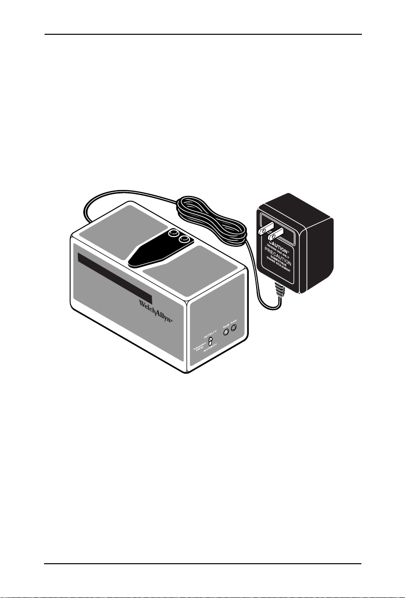
MAJOR COMPONENTS OF THE 9600
TEMPERATURE SELECT SWITCH
The Temperature Select Switch and the POWER and READY Indicators are
located on the front of the Main Unit. Whenever the unit is plugged into a
standard wall outlet, the POWER indicator will illuminate. There is no
power ON/OFF switch. The READY indicator will only illuminate when the
temperature stabilizes at the temperature you have selected on the Temperature Select Switch.
NOTE: For specific operational details about the components of the 9600
Calibration Tester, see the Specifications Section at the end of this manual.
POWER INDICATOR
When unpacking the 9600 Calibration Tester, notice that the Power Module
is permanently connected to the Main Unit. This is to assure a continuous
power supply to the unit, since intermittent power would cause the unit to
lose temperature control and would turn off the READY Indicator.
After the 9600 warms up, the unit will draw about 7 watts of power from a
standard wall outlet; therefore, it may be left on continuously. However, if
the unit will not be used for long periods of time, it may be unplugged.
READY INDICATOR
The 9600 Calibration Tester contains an independent temperature sensing
circuit that senses temperature changes more precisely than the thermometers it tests.
Because the unit contains this independent circuitry, a failure in the temperature-control circuit will not alter its “READY-sensing” ability . It is virtually
impossible for the READY indicator to illuminate if the temperature is
incorrect.
NOTE: Do not use the unit if the READY indicator is not illuminated. If the 9600
does not show “Ready” within a few minutes of the time allowed in the
Specifications Section of this manual, and the environment is within acceptable
operating conditions, the unit is malfunctioning and should be returned to the
factory for repair or replacement.
5
Page 6

Welch Allyn 9600 Calibration T ester
OVER-TEMPERATURE DETECTOR
In addition to the READY Indicator, the 9600 Calibration Tester contains an
“Over-Temperature Detector.” This is a fail-safe feature that protects the
unit against over-temperature conditions, in the unlikely event that a failure
should occur in the temperature-control circuitry. The over temperature
control circuit overrides the normal control circuit, and holds the temperature slightly above the set point.
If a failure were to occur in the circuitry and it caused the unit to keep
heating indefinitely, the Over-Temperature Detector would activate as soon
as the temperature rose a few tenths of a degree above the set point. If this
were to happen, the READY indicator would not illuminate, thereby alerting
the user that the unit should not be used.
THERMOMETER HOLES
The internal “blackbody” of the 9600 Calibration Tester acts as a heat
reservoir for the thermistor probe and as a heat radiator for the infraredsensing aural thermometer.
The large hole under the flap in the top of the Main Unit is for Model 9000
infrared (IR) Aural thermometers and the small hole is for thermistor-based
thermometers. For proper positioning of the thermometers in these holes,
see the following section, “Using the 9600 System.”
The surface texture inside the large hole must be flat (dull) and dry for
proper IR readings. This hole should be black; you should only be able to
see its surface under bright light. The small hole, which is not painted black,
must be kept clean and dry.
The coating in this part of the unit is fragile, so please follow the cleaning
instructions carefully. The surface of the unit should not be touched, nor
should any foreign objects be inserted into the unit. It also is important to
avoid spilling liquids onto the unit, even though it has a dust cover. If liquid
or other contaminants are allowed to enter the unit, proper calibration
cannot be assured.
6
Page 7

Operation Manual
USING THE 9600 SYSTEM
SETUP PROCEDURE
The 9600 Calibration Tester takes about 20 minutes to cool from its high
setting to its low setting. When testing several thermometers at both
temperatures, first test the units on the cool setting. Then switch settings,
wait for the READY indicator to illuminate, and test the thermometers at the
high setting.
To prepare the system for use, place the 9600 Calibration Tester on a level
surface away from sunlight, drafts, and other heat and cold sources. Then
take the following steps:
1. Set the Temperature Select Switch to the 96.4 ºF position.
2. Plug the power adapter into a wall outlet.
3. Verify that the POWER indicator is on. If the POWER indicator is not
on, check the connection to the power source, and verify that the outlet
has power. Do not open the unit as there are no parts that can be
serviced in the field. If the unit is opened, the warranty will become
void.
4. W ait until the READY indicator lights continuously. The unit will take
about 6 minutes to stabilize during which time the READY indicator
might blink on and off briefly before staying on continuously.
5. After obtaining a temperature (as described in the following sections),
switch the temperature setting to 106.0 ºF, and wait for the READY
Indicator to light continuously. This will take about 4 minutes.
LEVEL 1 CALIBRA TION TEST
Level 1 Calibration Test is described on the instruction label on the top panel
of the unit and in the following instructions. If a reading in the 9600 Tester
is less than, or equal to, +/-0.3 ºF from the temperature selected on the
9600, then the instrument is within specifications and no further testing is
needed.
7
Page 8

Welch Allyn 9600 Calibration T ester
THE MODEL 9000 AND MODEL 9020 THERMOMETER
1. The Model 9000 (InstaTemp® and ThermoGuide™) Thermometer can
be placed into a special Test Mode for checking the calibration using the
9600 System.
The Test Mode is entered by simultaneously pressing the PULSE,
TIMER, and MODE switches and is signified by a ‘T’ displayed on the
thermometer LCD.
The Test Mode will remain on as long as the “pulse timer” is active.
Once in the Test Mode, the mode may be extended by repeatedly
pressing the PULSE TIMER switch only. The Test Mode is exited
automatically when the “pulse timer” times out. The thermometer mode
will then change back to the thermometer mode prior to entering the
Test Mode. The Test Mode may be exited before the “pulse timer”
times out by pressing the MODE switch only. This will cause the
thermometer mode to change to the ORAL mode.
NOTE: For thermometers having serial numbers less than 25000, the Test
Mode is entered as an Operation Mode by repeatedly pushing the MODE
switch, For these thermometers, the Test Mode will remain until the mode is
manually changed - it will not automatically change back to the previous mode.
2. When the ready indicator is visible, push the slide forward to place a
probe cover on the sensor.
3. Inspect the probe cover for integrity. If the probe cover is damaged,
retract the slide fully to remove the damaged probe cover, When the
ready indicator is visible, push the slide forward to replace the probe
cover and then reinspect the integrity of the new cover.
4. Lift the flap and insert the tip of the Model 9000 Thermometer into the
large opening on the 9600 Calibration Tester until it rests on top,
perpendicular to the tester.
5. Immediately after inserting the thermometer, depress the scan button
until you hear the temperature completed beep (about 3 seconds), then
remove the thermometer from the 9600 Tester.
6. Verify that the reading on the Model 9000 Thermometer is within the
following tolerances:
96.4ºF Setting: 96.1ºF to 96.7ºF
106.0ºF Setting: 105.7ºF to 106.3ºF
8
Page 9

Operation Manual
THERMISTOR THERMOMETERS
(Please note that the following procedure reflects the Model 600 series and
later thermometers. When testing the Model 500, follow these instructions
where possible.)
1. Set the thermometer to Monitor Mode and Fahrenheit (ºF) following the
instructions in the Users’ Manual for the instrument to be tested.
2. Extract the probe from its holder, but do not load a probe cover.
3. Lift the flap and insert the probe fully into the small hole in the top of
the 9600 Tester (the probe will go in approximately 1 3/4").
4. Wait 2 minutes for the temperature to fully stabilize.
5. Verify that the reading on the thermometer is within the following
tolerances:
96.4ºF Setting: 96.1ºF to 96.7ºF
106.0ºF Setting: 105.7ºF to 106.3ºF
See “Level 2 Calibration Test” to test units outside of these limits.
CELSIUS-ONLY THERMISTOR THERMOMETERS
1. Where possible, follow the instructions for the Model 600 series
Thermometer.
2. The Fahrenheit Mode is the preferred mode for calibration testing of
thermometers, because the temperature units (degrees) are smaller, and
give a more accurate test. Therefore, whenever possible, use this mode.
3. For Celsius-Only Units, use the following conversion table for testing
the calibration of the thermometer.
Fahrenheit ºCelsius ºFahrenheit ºCelsius
º
96.0 35.6 105.6 40.9
96.1 35.6 105.7 40.9
96.2 35.7 105.8 41.0
96.3 35.7 105.9 41.1
96.4 35.8 106.0 41.1
96.5 35.8 106.1 41.2
96.6 35.9 106.2 41.2
96.7 35.9 106.3 41.3
96.8 36.0 106.4 41.3
9
Page 10

Welch Allyn 9600 Calibration T ester
LEVEL 2 CALIBRA TION TEST
Usually thermometer calibration will fall within the +/-0.3ºF tolerance limit
when tested in the 9600 Calibration Tester. This tolerance is the result of
two elements: the thermometer system contributing +/-0.2ºF, and the 9600
Tester contributing +/-0.1ºF to the test reading.
If a Level 1 reading is greater than +/-0.3ºF from the temperature selected,
try the “Level 2 Calibration Test”. If the Level 2 Test is not successful, then
proceed to the TROUBLESHOOTING Section.
There are several variables that must be checked before concluding that a
thermometer is out of calibration. They are described on the following
pages.
LEVEL 2 CALIBRATION TEST
If the Level 1 Calibration Test is not successful - that is, if the reading is
greater than +/-0.3ºF from the temperature selected - conduct the Level 2
Calibration T est.
1. Check to see that the 9600 READY indicator is on continuously. It
should not go out unless the temperature selection is changed. If the
READY indicator goes out occasionally, be sure the unit is away from
drafts, direct sunlight, and other heat and cold sources, and that there is
continuous power to the unit.
If the READY indicator does not come on, but the unit reads close to
the temperature selected then there is an internal malfunction and the
temperature is being controlled by the Over-Temperature Protection
Circuitry. This temperature is not a calibrated temperature and cannot
be used to test thermometers. If this should happen, the 9600 Unit
should be returned to the factory for repair.
2. Check the temperature of the room. It must be within 65ºF and 80ºF
(18.3ºC and 26.7ºC).
3. For Model 9000 and Model 9020 Thermometers, use the following
procedure.
n Ensure that the sensor is free from debris. To do this, first load a
probe cover, then peel the probe cover off the tip. If the tip appears
clean, retract the probe. If you see dust or other debris on the tip,
clean the surface following the first 2 steps of the procedure in the
Model 9000 CALIBRATION ADJUSTMENT Section of this manual.
10
Page 11

Operation Manual
n With a clean tip, load a new probe cover and take three readings in
the 9600 Tester at each temperature. Inspect the probe cover for
integrity and proper loading before each reading. If any tears in the tip
of the probe cover are found, discard the probe cover and load
another one. If all six readings are +/-0.3ºF or less from the temperatures selected, the thermometer is within tolerance. If any reading is
+/-0.4ºF or greater, proceed to the TROUBLESHOOTING section.
4. For Thermistor Thermometers, use the following procedure.
Check the connections between the probe and the thermometer. If the
probe cable is cracked or frayed, replace the probe. If the probe shaft is
bent or loose in the handle, or otherwise damaged, replace the probe. If
there are no problems with the probe, disconnect and reinsert it into the
thermometer, and take another reading. If the reading is no more than
+/-0.3ºF from the temperature selected, then the unit is within tolerance. If the reading is +/-0.4ºF or greater, proceed to the TROUBLESHOOTING section.
TROUBLESHOOTING
Follow the troubleshooting procedure if a reading from the previous testing
levels is more than +/-0.3ºF from the temperature selected on the 9600
Tester.
If the procedures for the Level 1 and Level 2 Calibration Tests have been
followed and the tests were unsuccessful, chances are that the unit is out of
calibration. However, before replacing the unit, complete the following
steps.
MODEL 9600 CALIBRATION CHECKS
If several thermometers do not pass the Level 1 or Level 2 Calibration
Tests, there is a chance that the 9600 Tester is out of calibration. There are
several variables that can be checked to verify if the unit is out of calibration.
1. Check the calibration date on the front of the 9600 Tester. The unit
must have calibration validated annually .
2. Make sure that the 9600 Tester has not been opened. If the calibration
label has been tampered with, the calibration and the warranty will be
void.
11
Page 12

Welch Allyn 9600 Calibration T ester
3. Ensure that the unit has not been exposed to extreme temperatures that
can damage the precision thermistors in the 9600 Tester. Exposure to
high heats can cause the resistance vs. temperature characteristic of the
unit to shift, causing the 9600 Tester to lose calibration. Never auto-
clave the 9600 Tester.
ENVIRONMENTAL CHECKS
1. Make sure there is no excessive moisture or steam in the air. High
humidity (above 96%) can cause electrical leakages that can temporarily
shift the temperature out of calibration. If the thermometers and/or the
9600 Tester have been exposed to such conditions, they should be
allowed to sit at normal room temperature for at least 30 minutes before
a calibration test is conducted.
2. Thermal gradients in the thermometer or the 9600 Tester can cause
unpredictable effects.
Two examples of exposure to extreme temperatures are:
n Carrying the thermometer between buildings on a cold winter day,
n Exposing the thermometer to the sun on a window sill.
3. Test the calibration at or near the normal room temperature for use of
the thermometer. If the room temperature is at the extreme ends of the
specified temperature range, a unit that is within specification under
normal usage temperatures could be out of calibration.
MODEL 9000 CALIBRA TION ADJUSTMENT
This procedure allows for manual calibration adjustments of a Welch Allyn
Model 9000 Thermometer which has failed the Troubleshooting Test
described in this manual.
The Model 9000 (InstaTemp® and ThermoGuide™) Thermometer can be
placed into a special Test Mode for checking the calibration using the 9600
System.
The Test Mode is entered by simultaneously pressing the PULSE, TIMER,
and MODE switches and is signified by a “T” displayed on the thermometer
LCD.
12
Page 13

Operation Manual
The Test Mode will remain on as long as the “pulse timer” is active. Once in
the Test Mode, the mode may be extended by repeatedly pressing the
PULSE TIMER switch only. The Test Mode is exited automatically when
the “pulse timer” times out. The thermometer mode will then change back
to the thermometer mode prior to entering the Test Mode. The Test Mode
may be exited before the “pulse timer” times out by pressing the MODE
switch only. This will cause the thermometer mode to change to the ORAL
mode.
NOTE: For thermometers having serial numbers less than 25000, the Test
Mode is entered as an Operation Mode by repeatedly pushing the MODE
switch. For these thermometers, the Test Mode will remain until the mode is
manually changed - it will not automatically change back to the previous mode.
PRIOR TO CALIBRATION ADJUSTMENT
The sensor lens must be absolutely clean. If the lens is not clean, perform
the following cleaning procedure twice prior to calibration:
n Using a cleaning swab slightly moistened with isopropyl alcohol,
clean the surface with a gentle circular motion. Immediately wipe the
lens with a clean, dry swab using the same circular motion.
n After cleaning the lens, allow at least 60 minutes for the sensor to
stabilize before taking temperatures with the thermometer.
n Set the Model 9600 Calibration Tester to the 106ºF position.
n Set the thermometer to be adjusted to the Test Mode (T) and Fahren-
heit (F) display.
ESTABLISHING A BASELINE PRIOR TO MAKING
CALIBRATION ADJUSTMENTS
Take 2 temperatures into the 106ºF opening of the 9600 from each of 5
different probe cover dispensers and record the readings. The 10 readings
are then averaged to compute the present thermometer calibration.
13
Page 14

Welch Allyn 9600 Calibration T ester
SETTING THE THERMOMETER TO THE CALIBRATION
ADJUSTMENT MODE
1. Insert the thermometer into a wall mount.
2. Move the slide forward and then press the scan switch and activate the
mode switch simultaneously.
3. Remove the thermometer from the wall mount and retract the slide.
Move the slide forward and activate the mode switch. The mode
display should indicate “O” with “OO” on the main display if no prior
adjustment has been made.
4. Use the F/C switch to increase the number and the Pulse switch to
decrease the number according to the following table:
10 Temperature Average
Reading with Probe Cover New Calibration Number
105.6 Old number + l0
105.7 Old number + 8
105.8 Old number + 5
105.9 Old number + 3
106.0 Old number + 00
106.1 Old number - 03
106.3 Old number - 09
106.4 Old number - 10
5. Retract the slide and retest the thermometer in a black body with probe
covers using the 2 covers from 5 dispensers as above.
14
Page 15

Operation Manual
SPECIFICATIONS
Power Requirements
Voltage ll5 VAC +/-10%, 60 Hz (220VAC
+/-10%, 50 Hz for European)
Current
Heating 130 mA
After Warm-Up 60 mA
Internal Fuse Rating 1.6A
Power Consumption
Heating 15.6W
After Warm-Up 7.2W
Mechanical
Main Unit
Length 150 mm (5.9")
Width 80 mm (3.15")
Height 80 mm (3.15")
Power Pack (approximate dimensions)
Length 83 mm (3.25")
Width 61 mm (2.4")
Height 76 mm (3.0")
Weight 20 lbs
Environment
Storage Temperature 32ºF - 122ºF (0ºC - 50ºC)
Operating Temperature Range 65ºF - 80ºF (183ºC - 26.7ºC)
Operating Humidity 20% to 90% RH. Non-Condensing
Operating Specifications
Controlled Temperature of 9600
Low Setting 96.4ºF
High Setting 106.0ºF
Temperature Tolerance +/-0.1ºF
READY Indicator Temperature
Tolerance +/-0.1ºF
Heating and Cooling Times
Time to Heat to Low Setting from
Room Temperature 6 min.
Time to Heat to High Setting from
Low Setting 4 min.
Time to Cool from High Setting to
Low Setting 20 min.
15
Page 16

LIMITED W ARRANTY
Instrumentation purchased new from Welch Allyn is warranted to be free
from defects in material and workmanship under normal use and service for
a period of one year from the date of first shipment from Welch Allyn. This
warranty shall be fulfilled by Welch Allyn or its authorized representative
repairing or replacing, at Welch Allyn’s discretion, any such defect free of
charge for parts and labor.
Welch Allyn should be notified via telephone of any defective product and
the item should be immediately returned, securely packaged and postage
prepaid
to Welch Allyn . Loss or damage in shipment shall be at purchasers’ risk.
Welch Allyn will not be responsible for loss associated with the use of any
Welch Allyn Product that (1) has had the serial number defaced, (2) has
been repaired by anyone other than an authorized Welch Allyn Service
Representative, (3) has been altered, or (4) has been used in any manner
other than in accordance with instructions.
THIS W ARRANTY IS EXCLUSIVE AND IN LIEU OF ANY IMPLIED
W ARRANTY OF MERCHANT ABILITY, FITNESS FOR P AR TICULAR
PURPOSE, OR OTHER W ARRANTY OF QUALITY, WHETHER
EXPRESS OR IMPLIED, W elch Allyn WILL NOT BE LIABLE FOR
ANY INCIDENT AL OR CONSEQUENTIAL DAMAGES.
(800) 854-2904 • (619) 621-6600 • fax (619) 621-6611
W elch Allyn, Inc. San Diego, CA 92121
© 1998 Welch Allyn, Inc. All Rights Reserved. 70578-000C
 Loading...