

Page 1

Service Manual
Thermo Menu
Operator Manual
®
SureTemp
Model 986 Thermometer
Welch Allyn, Inc.
7420 Carroll Road
San Diego, CA 92121
Page 2

70995-0000B Technical Manual M986 © 2001
© 2000, 2001 by Welch Allyn, Inc. All rights reserved. No part of this manual may be
reproduced or transmitted in any form or by any means, electronic or mechanical, including
photocopy, without prior consent in writing from Welch Allyn, Inc. Printed in the USA
Welch Allyn and SureTemp are trademarks of Welch Allyn, Inc. All rights reserved.
Page 3

Contents
1. General Information...................................................................................................... 1
1.1 About the Model 986................................................................................................. 1
1.1.1 System Block Diagram................................................................................... 1
1.2 Technical Support .....................................................................................................1
1.3 Safety Warnings and Notices .................................................................................... 2
1.4 Classifications.......................................................................................................... 2
1.5 About this Manual .................................................................................................... 3
1.5.1 Related Documents........................................................................................ 3
1.6 Return Procedure ..................................................................................................... 3
1.7 Terms used in this Manual ........................................................................................ 4
2. Service .......................................................................................................................... 5
2.1 Basic Operation of the Model 986 .............................................................................. 5
2.1.1 Types of units ................................................................................................5
2.1.2 Major Thermometer Components .....................................................................6
2.1.3 Instrument Reset ........................................................................................... 6
2.1.4 POST (Power Up Self-Test)............................................................................. 7
2.1.5 Probe Type Test ............................................................................................ 7
2.1.6 Operational Checks........................................................................................ 8
2.1.7 Default algorithm for oral and axillary modes (blue probe) ................................11
2.2 Service Procedures .................................................................................................11
2.2.1 List of Tools and Equipment..........................................................................11
2.2.2 Preventative maintenance.............................................................................12
2.2.3 Cleaning and Sterilization .............................................................................13
2.2.4 Service Activities ..........................................................................................14
2.2.5 Component Replacement ..............................................................................14
2.3 Battery Removal and Replacement ...........................................................................15
2.3.1 Battery Life..................................................................................................15
2.4 Calibration Procedures............................................................................................16
2.4.1 Calibration Limits Table ................................................................................16
2.4.2 Water Bath procedure ..................................................................................16
2.4.3 Variable Temperature Water Bath procedure...................................................16
2.4.4 Model 9600 Calibration procedure ..................................................................17
3. Troubleshooting ..........................................................................................................19
3.1 Error Codes ...........................................................................................................19
3.1.1 Types of Errors ............................................................................................20
3.1.2 Error Recall Mode........................................................................................21
3.2 Troubleshooting Table.............................................................................................22
3.3 Disassembly/Reassembly.......................................................................................24
3.4 Field Serviceable Parts ...........................................................................................24
3.4.1 Main Components ........................................................................................24
3.4.2 Model 986 PCA ...........................................................................................26
Model 986 Thermometer i
Page 4

3.4.3 Replacement Parts for PCA ..........................................................................27
Appendix A. Theory of Operation.....................................................................................29
A.1 Overview................................................................................................................29
A.1.1 Temperature Probes.....................................................................................30
A.1.2 Probe Switch...............................................................................................30
A.1.3 Normal Mode Description..............................................................................30
A.1.4 Power Supply..............................................................................................31
A.1.5 Microcontroller.............................................................................................31
A.1.6 Reset/Self Tests..........................................................................................31
A.1.7 Microprocessor Clock...................................................................................32
A.1.8 Temperature Measurement And Display.........................................................32
A.2 Temperature Measurement A/D Converter .................................................................32
A.2.1 Use of Analog Circuitry.................................................................................32
A.2.2 A/D Theory of Operation ...............................................................................32
A.2.3 Circuit Description........................................................................................33
A.2.4 Probe Type Detection ...................................................................................34
A.2.5 Instrument ID Logic......................................................................................34
A.2.6 Circuit Operation ..........................................................................................34
A.3 Probe warming (Oral probes only)............................................................................35
A.3.1 Theory of Operation ......................................................................................35
A.3.2 Circuit Operation ..........................................................................................35
A.3.3 Liquid Crystal Display ...................................................................................36
A.3.4 Probe Switch...............................................................................................36
A.3.5 Mode Button................................................................................................36
A.3.6 Horn ...........................................................................................................37
Appendix B. Specifications .............................................................................................. 39
Appendix C. Limited Warranty ......................................................................................... 41
Appendix D. Wiring Diagram ...........................................................................................43
ii 70995-0000B M986
Page 5

List of Figures
Figure 1: System Block Diagram .............................................................................................. 1
Figure 2: Model 986 Thermometer .............................................................................................5
Figure 3: M986 Display ............................................................................................................ 7
Figure 4: Peak Monitor Mode.................................................................................................... 9
Figure 5: Battery Removal and Replacement............................................................................15
Figure 6: Thermometer Assembly ...........................................................................................24
Figure 7: Printed Circuit Assembly ..........................................................................................26
Figure 8: System Block Diagram ............................................................................................29
Figure 9: Schematic Diagram .................................................................................................43
List of Tables
Table 1: Self-Test Error Table..................................................................................................20
Table 2: Main Components .....................................................................................................25
Table 3: Replacement Parts for PCA .......................................................................................27
Table 4: Configuration Truth Table ...........................................................................................34
Model 986 Thermometer iii
Page 6

iv 70995-0000B M986
Page 7
1. General Information
1.1 About the Model 986
The Welch Allyn Model 986 SureTemp is a portable, predictive
thermometer that accurately measures body temperatures in a
few seconds at oral, axillary, or rectal sites. Oral/axillary and rectal
probes utilize single use disposable probe covers to help limit
cross-contamination.
This instrument was developed for use by medical professionals
and day care providers. The predictive technology allows the user
to take oral temperatures in approximately four seconds, axillary
temperatures in approximately 10 seconds (for children under four
years), and rectal temperatures in approximately 15 seconds.
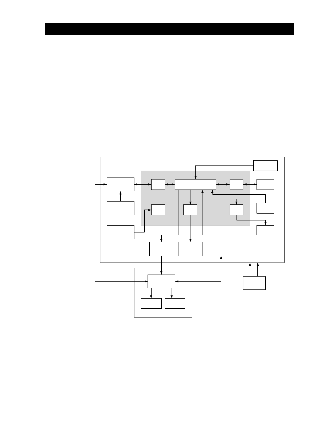
1.1.1 System Block Diagram
Model 986 PCA
A/D Converter
Circuit
Voltage
Reference Circuit
Battery Detector
Circuit
NEC UPD 789407 uP
16 Bit
Timer
8 Bit
A/D
Probe Warmer
Circuit
Four Conductor
Coil Cord
Thermistor
Probe Assembly
Probe
Warmer
CPU
LCD
Driver
Liquid Crystal
Display
Probe
Configuration
Jumpers
Serial
I/O
Horn
Driver
2 AAA
Batteries
Configuration
Serial
Port
Mode
Button
Horn
Figure 1: System Block Diagram
1.2 Technical Support
Contact Welch Allyn Customer Service at:
Welch Allyn, Inc
7420 Carroll Road
San Diego, CA 92121
Model 986 Thermometer 1
800-535-6663
Page 8

1. General Information
1.3 Safety Warnings and Notices
1. DO NOT USE THIS INSTRUMENT IN THE PRESENCE OF
FLAMMABLE ANESTHETICS.
2. Do not use this instrument for any purpose other than those
specified in the User’s Guide. Doing so will invalidate the
instrument’s warranty.
3. Oral/Axillary SureTemp thermometer models (with a blue
ejection button at the top of the probe) are to be used for taking
oral and axillary temperatures only. Rectal models (red
ejection button) are to be used for taking rectal temperatures
only. Use of a probe at the wrong type of site will result in
temperature errors.
4. Use only single-use Welch Allyn disposable probe covers. The
use of any other probe cover or the failure to use a probe cover
may produce temperature measurement errors and increase
the chances for cross-contamination.
5. The thermometer case is not waterproof. Do not immerse it in
liquids or drip fluids onto it.
6. Dispose of batteries in accordance with all local, state and
federal environmental guidelines.
7. This instrument consists of high quality precision parts and
should be protected from severe impact and shock. Do not use
the thermometer if you notice any signs of damage to the
probe or instrument. Contact Welch Allyn Customer Service at
(800) 535-6663 for immediate assistance.
Note: This thermometer complies with current required
1.4 Classifications
Type of protection against
Degree of protection against
Degree of protection against
standards for electromagnetic interference and should
not present a problem to other equipment or be affected
by other devices. As a precaution, avoid using this
device in close proximity to other equipment.
Internally Powered Equipment
electric shock
Type BF Applied Part
electric shock
Ordinary (IPXO)
ingress of liquids
Degree of safety in the
presence of flammable
anesthetics
Mode of operation Continuous
2 70995-0000B M986
Equipment not suitable for use
with flammable anesthetics
Page 9

1.5 About this Manual
This manual describes both the Model 986 Oral/Axillary and Rectal
thermometers. Most topics and procedures are equally applicable
to both products. Where there are differences, we will note which
instrument is being discussed.
1.5.1 Related Documents
End user operation of the Model 986 is covered in the M986
User Guide and Quick Reference Guide.
Model 986 User Guide 70994-1000
Model 986 Quick Reference Guide 71019-0000
This Service Manual assumes that the technician understands
these operations.
1.6 Return Procedure
1. General Information
Contact Welch Allyn Customer Service at (800) 535-6663 before
returning an M986 Thermometer to the factory for service.
Model 986 Thermometer 3
Page 10

1. General Information
1.7 Terms used in this Manual
The following abbreviations are used in this manual:
Main Component Terms
PCB Printed circuit board (the board itself)
PCA Printed circuit assembly (with all components)
LCD Liquid Crystal Display
BATT. Battery.
DMM Digital Multi-Meter
O-Scope Oscilloscope
Component Reference Terms
C Capacitor
D Diode
E Test point
J Connector jack
L Inductor
LS1 Horn
P Connector plug
Q Transistor
R Resistor
S Switch
U Integrated circuit
X Crystal, resonator
4 70995-0000B M986
Page 11
2. Service
2.1 Basic Operation of the Model 986
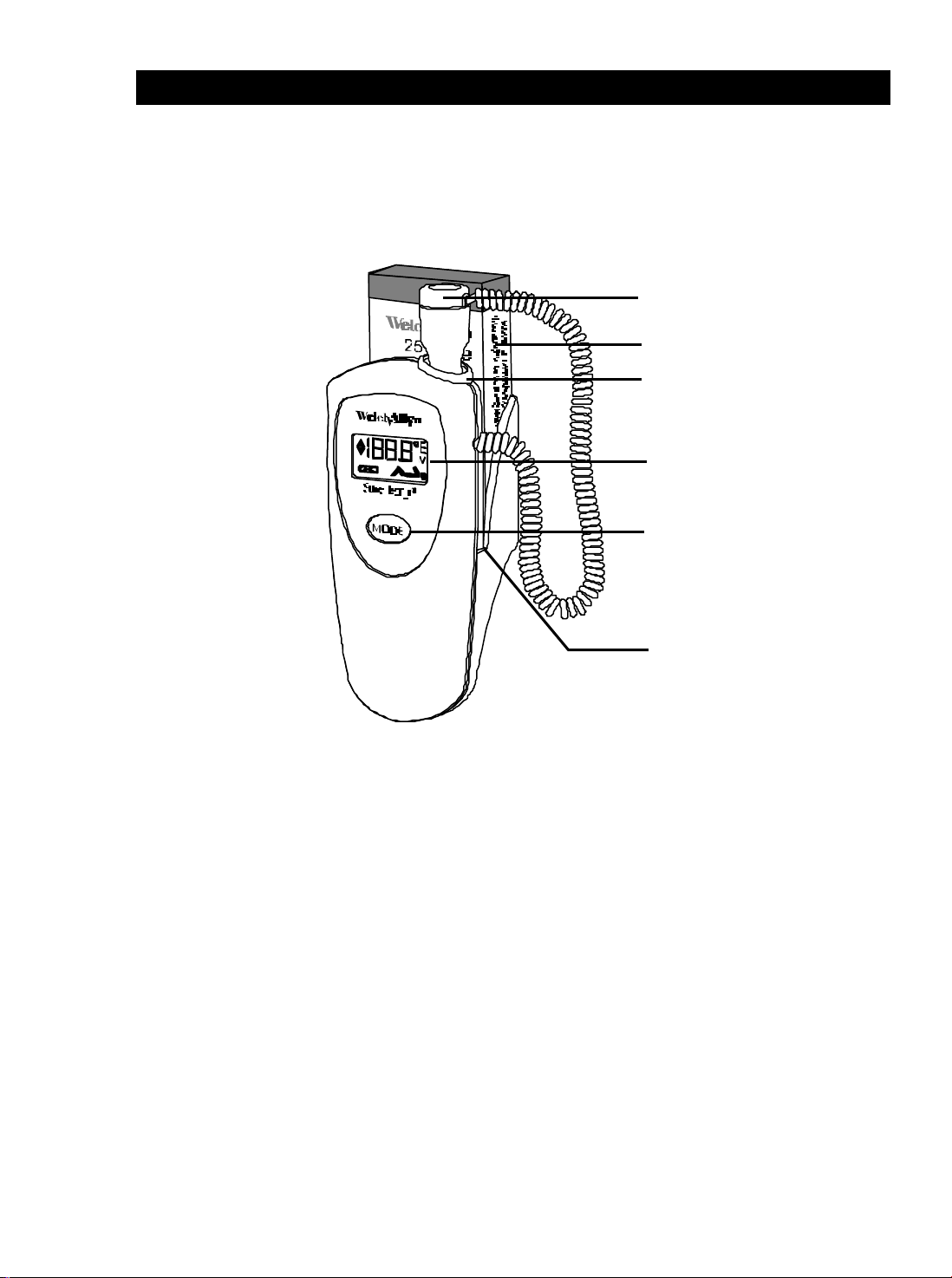
The Model 986 is a portable digital thermometer. Service
technicians should check the basic operation of the instrument
before it is disassembled.
1 Probe cover ejection button
2 Probe cover box
3 Probe storage channel
4 LCD display
5 Mode button
2.1.1 Types of units
The M986 is available from the factory in the following
configurations:
• Oral /Axillary or Rectal Probe
• ° F/°C, ° F Only, °C Only
Note: Thermometer configuration cannot be modified in the field.
6 Battery Compartment
Figure 2: Model 986 Thermometer
Model 986 Thermometer 5
Page 12

2. Service
2.1.2 Major Thermometer Components
Batteries The Model 986 thermometer uses two standard
disposable alkaline AAA cells. These batteries
provide long life for reduced down time. No battery
charging is required or possible.
Probe Two types of probes are available: Oral/Axillary
(blue), and Rectal (red). The probe is not detachable
and is connected to the printed circuit board at the
factory.
Probe
Covers
The probe covers are unchanged from previous
models and are compatible across all of Welch
Allyn’s thermistor-based thermometers.
Note: The use of probe covers other than Welch
2.1.3 Instrument Reset
If a problem is reported with an instrument, please check its
operation before resetting it.
Reset Procedure
1. Remove the batteries from the instrument (see page 15).
2. After battery removal, any remaining charge due to internal
capacitance must be discharged to achieve a proper reset.
After the batteries are removed, press the Mode button for
about five seconds. The electronics will now properly reset
when the batteries are replaced.
3. Reinstall the batteries. Watch the display and observe the
power up self-test (page 7).
Allyn PN 05031 is not allowed, and will affect
the accuracy of the instrument.
6 70995-0000B M986
Page 13

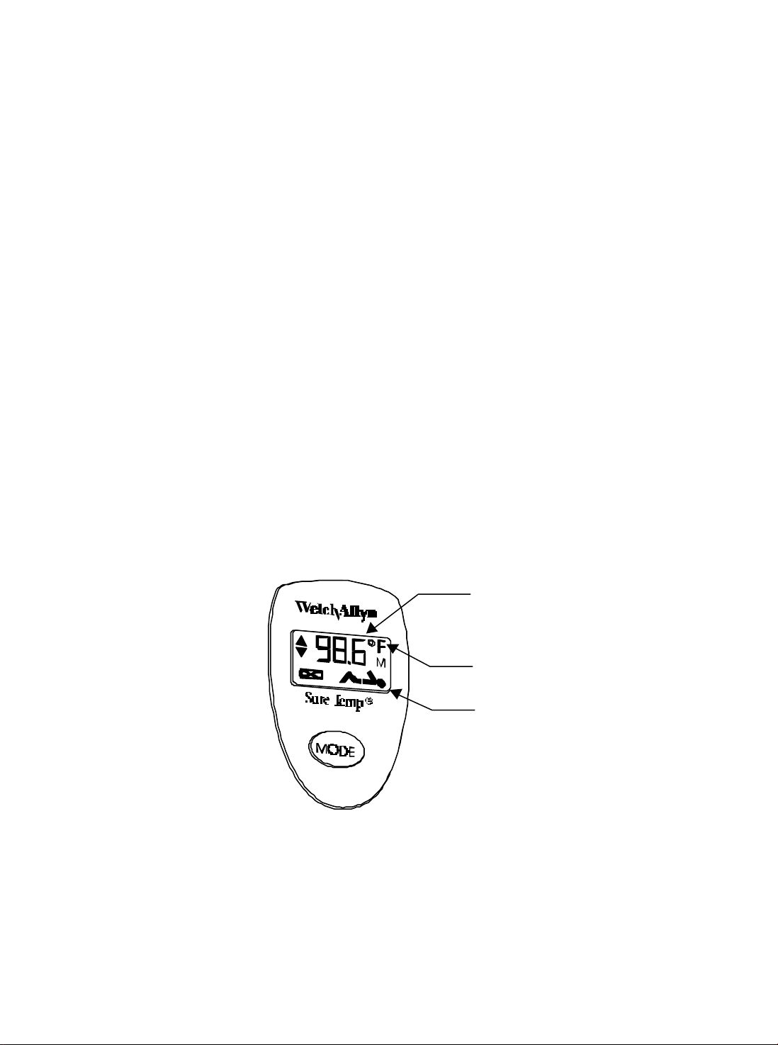
2.1.4 POST (Power Up Self-Test)
The self-test includes a series of internal microprocessor self
tests, instrument electronics tests, and the display test. If there are
internal electronics problems detected by the self-tests, the Err
(error) icon will be displayed and an audible tone will sound. Refer
to the Error Codes table in the Troubleshooting section (page 19)
for an explanation of any error code. The M986 electronics are
tested each time the batteries are replaced.
• The Power up test begins with all display segments and icons
simultaneously illuminated, followed by a display of the
software revision in this instrument. The M986 beeper also
briefly sounds at the beginning of the test.
Figure 3: M986 Display
2. Service
• At the end of the test, the display goes blank and the unit is
ready to operate.
If there is no display, any missing segments, or no beeper, refer to
the Troubleshooting table (page 22).
2.1.5 Probe Type Test
Test the probe to make sure that the correct type of probe is
attached to the unit.
With the probe shaft in the probe well and the display blank, press
the Mode button for three seconds. After three seconds, the
instrument will beep and the display shows the icon with
the measuring site blinking.
• For a blue (oral/axillary) probe, either the head or arm should
blink, depending on whether the instrument is configured for
Oral or Axillary measurements.
• With a red (rectal) probe, the leg icon should blink.
If the wrong icon is blinking, there is a problem with either the probe
or the probe type configuration in the instrument.
1. Refer to the mode table on the schematic diagram (Appendix D).
2. In the mode table, locate the type of instrument – oral only,
rectal only, etc. that you are using.
3. Open the thermometer and locate the jumpers. Verify that the
jumpers are configured for your type of unit.
4. If the jumpers are not configured properly, contact Welch Allyn
Customer service for assistance.
Model 986 Thermometer 7
Page 14

2. Service
2.1.6 Operational Checks
Normal Mode
Normal mode operation is the rapid mode of temperature taking.
This is the default mode and is automatically selected when the
probe is withdrawn from the probe well.
1. When the probe is withdrawn from its storage well, every
segment on the display will be illuminated. Watch for the
display to change from the all segments test to the body icon
display.
2. When the unit is ready, it will beep. The °F or °C symbol
(whichever is selected) will illuminate, and the measuring site
(oral, axillary, rectal) will begin to blink.
3. Load the probe cover at this time. The instrument is now ready
for the probe to be placed in the measuring site.
Note: It is possible that the display will switch from the measuring
site display to the “walking segments” display and back
again several times before the probe is inserted in the site.
This is acceptable operation and will not adversely affect
the temperature taken.
Monitor Mode
The thermometer will automatically switch to Monitor Mode under
certain conditions:
• If the instrument determines that room temperature is above
33.9°C (93.0°F).
• If the thermometer is unable to predict a temperature, after 15
seconds for Oral/Axillary and 30 seconds for rectal, due to
improper technique such as excessive probe movement at any
patient site (i.e. mouth, rectum, axillary).
Note: The thermometer reads the probe temperature immediately
upon removal from the storage well. If the probe was just
replaced from a previous temperature and immediately
extracted, insufficient time may have passed to allow the
probe to cool to room temperature. This will cause the
instrument to determine room temperature to be higher
than actual. The instrument will switch to Monitor mode
immediately if it detects room temperature to be above 33.9
°C (93.0°F). For best results, the user should wait at least
30 seconds between Normal mode temperature
measurements.
If Monitor mode does not display expected temperatures, refer to
the Troubleshooting table on page 22.
8 70995-0000B M986
Page 15
2. Service
Temperature Display
With correct use, the patient’s temperature will be displayed in
about four seconds in oral mode, about 10 seconds in axillary
mode, and about 15 seconds with a rectal probe. The instrument
will beep to signal completion of the Normal Mode temperature
cycle.
Automatic Shutoff
If the probe is left out of the storage well after completion of a
Normal mode temperature, the unit will shut off automatically after
10 seconds to conserve power. Simply replace the probe in the
storage well to prepare for the next temperature.
The instrument will shut off automatically if the probe temperature
remains below 28.9°C (84.0°F) for more than 30 seconds.
Peak Monitor Mode
Peak Monitor mode allows long term monitoring of a patient’s peak
temperature. Unlike predictive mode, Peak Monitor mode will follow
a temperature as it rises and display this temperature until the
probe detects a higher temperature. When this occurs, the higher
temperature is displayed.
Peak Monitor mode provides a direct readout of the peak probe
temperature. The instrument can set in Peak Monitor mode by
immediately pressing the Mode button for two seconds after a
predictive (normal) temperature has been taken.
Constant
Temperature
Flashing
Body icon disappears
Figure 4: Peak Monitor Mode
Peak Monitor mode will be indicated on the display by a continuous
temperature reading with a blinking °°F or °°C Icon at the upper right
corner of the LCD, and by the body icon disappearing.
Model 986 Thermometer 9
Page 16

2. Service
The typical slow rise in temperature when Peak Monitor mode is
used is due mainly to the mouth temperature slowly recovering
from placement of the colder (room temperature) probe. The probe
itself is actually very fast at rising to the temperature of its
surroundings, usually reaching it within a few seconds. Because of
this slow mouth recovery, three minutes is the recommended time
to wait before recording a Peak Monitor mode temperature.
Peak Monitor mode is also useful in testing the accuracy of the
thermometer when the probe can be warmed to a known
temperature, as with a Welch Allyn Model 9600 Calibration Tester
or in a water bath (see section 2.4).
In Peak Monitor mode, after approximately 60 seconds of no
increase in temperature, the °°C / °°F icon stops flashing. You will
hear two triple beep sounds, and the peak temperature will be
displayed on the LCD.
Note: If the unit is left in Peak Monitor Mode for a total of five
minutes, it will automatically shut off to conserve power.
If Peak Monitor mode does not display expected temperatures,
refer to the Troubleshooting table on page 22.
°F / °C Conversion
When a final temperature is displayed (in Normal, Recall, or
Monitor mode), press and release the Mode button to toggle the
temperature between °F/°C.
Note: A recalled temperature will be displayed in whichever scale
(°F/°C) is selected at the time of recall. This setting can be
changed during display.
If pressing the Mode button does not change the scale of the
displayed temperature, refer to Mode Button Problems in the
Troubleshooting table on page 22.
Temperature Recall
With the instrument in low-power mode (sleep mode or blank display),
press and release the Mode button to cause the most recent
measured temperature to be displayed for five seconds. The stored
temperature value appears with a °F or °C symbol (whichever is
selected) and an M indicating it is from memory.
• If the recalled temperature was a normal mode temperature,
the flashing symbol of the measurement site is also displayed.
• If the recalled temperature was a Peak Monitor temperature,
only the temperature is displayed, with no site indicated.
Activation of the probe well switch (place the probe in the well) will
interrupt the temperature recall function.
10 70995-0000B M986
Page 17

Temperature recall problems
If the last temperature cannot be recalled, refer to Temperature
Recall Problems in the Troubleshooting table on page 22.
If pressing the Mode button does not change the scale of the
displayed temperature, refer to Mode Button problems in the
Troubleshooting table.
2.1.7 Default algorithm for oral and axillary modes
(blue probe)
Two predictive algorithms are available: oral and axillary. To
change the default algorithm:
1. Place the unit in low power mode.
2. Press and hold the Mode button for at least two seconds, until
a short beep is heard. The current algorithm will be displayed.
3. To advance to the next algorithm, press the Mode button
momentarily.
2. Service
Note: When replacing the batteries, the default power up setting is
the oral predictive algorithm.
2.2 Service Procedures
2.2.1 List of Tools and Equipment
Most service operations can be performed with standard tools and
test meters:
• A #1 Phillips screwdriver can be used for all instrument
screws.
• A standard lab 3.5 digit digital multi-meter (DMM) will provide
sufficient accuracy for most tests. A needle-tipped pair of
probes is recommended. An oscilloscope is sometimes the
only way to analyze high speed signals, but is not generally
required.
• Standard electronics tools and supplies for small surface-
mounted and through-hole component rework will be needed to
perform any electronics repairs. Some surface-mounted
components are extremely small and present a challenge for
rework by hand. A light touch, tweezers, sharp soldering iron
tip, and low heat (#7 tip) are recommended.
• Power (+) and ground (-) are available at the battery terminals.
• Be sure to service the instrument in an ESD-safe work area.
Model 986 Thermometer 11
Page 18

2. Service
2.2.2 Preventative maintenance
Units that are used on a regular basis should have the following
preventative maintenance performed at least every six months:
1. Visually inspect the thermometer for physical damage that
might cause future product failure.
2. Clean the unit per the instructions in the User Guide supplied
with the thermometer and/or per the instructions below.
3. Perform the Power on Self Test (page 7), Startup Display Test
(page 7), and the Calibration Test procedure (page 16).
Long Term Storage
Remove the batteries from units that are to be stored for an
extended period and not used.
Regular Tests and Calibration
Perform the following tests every 12 months regardless of storage
and usage levels:
1. Replace the batteries (page 15).
2. Perform the Power on Self Test (page 7), Startup Display Test
(page 7), and the Calibration Test procedure (page 16).
12 70995-0000B M986
Page 19

2.2.3 Cleaning and Sterilization
Routine Cleaning
Clean the exterior of the Model 986 and the probe as needed.
• Use a Q-Tip to clean the probe well.
• Wipe all surfaces with a clean cloth dampened with warm
water and a mild detergent, alcohol, or a nonstaining
disinfectant such as Sporicidin Spray1 and Towelettes
cleanser.
Care should be taken not to scratch the LCD faceplate. Make sure
that the cloth is damp, but not too wet.
• Do not allow cleaning solution to flow inside the instrument.
• Never immerse the thermometer into the cleaning solution.
• Never autoclave the thermometer or probe.
Gas Sterilization
2. Service
When no other form of decontamination such as a germicidal wipe
is acceptable, a low temperature (not to exceed 48.9°C or 120°F)
ETO gas sterilization cycle may be used. Refer to your institution’s
standard operating procedure for the length of the cycle.
Note: Gas sterilization may cause some hazing of glossy plastic
surfaces and should be used only when absolutely necessary.
1. Remove the probe from its storage well and disconnect it from
the instrument.
2. Remove any probe covers from the probe and from the probe
cover storage well.
3. Remove the batteries following the instructions on page 15.
WARNING: Leaving batteries in the thermometer during the
sterilization procedure may present an explosion
hazard.
4. Wrap the thermometer in standard sterilization packaging such
as the Baxter Tower Dualpeel Sterilization Pouch.
5. ETO gas sterilize the instrument at a temperature not to
exceed 48.9°C (120°F) and aerate.
6. Remove the sterilization packaging.
7. Allow the probe and instrument to stabilize to room
temperature for at least one hour before reinstalling the
batteries and probe.
1
Sporicidin is a registered trademark of Sporicidin International (800) 424-3733.
Model 986 Thermometer 13
Page 20

2. Service
8. Reinstall the batteries (see page 15) and verify a successful
self-test.
9. Reinstall the probe connector and insert the probe into the
storage well to start the probe initialization process.
10. Verify proper calibration of the thermometer and probe using
the Welch Allyn Model 9600 Calibration Tester.
2.2.4 Service Activities
Field Service Repairs
Repairs are considered field serviceable if the repair will not alter
the calibration or proper operation of the instrument. Recalibration
requires a computer-based system and is normally performed at
the factory.
Factory Repairs
Because of programming requirements, if problems are traced to
microcontroller U1, the unit must be returned to the factory or
properly equipped service center for repair.
2.2.5 Component Replacement
All components in the Model 986 can be replaced without affecting
instrument operation or calibration. Changing R13 will cause some
minor changes to the exact calibration point, but as long as the
proper type and tolerance resistors are used (0.05%, as supplied
by Welch Allyn), the unit will remain within specifications.
LCD Frame Repair or Replacement
Replacement of the LCD frame is somewhat difficult due to the
need to assemble it while under pressure to assure proper
compression of the elastomeric connector.
Note: Do not glue the LCD frame to the display PCB if the frame
pins are broken. This will destroy the display PCB. Replace
the LCD frame with a new LCD frame.
14 70995-0000B M986
Page 21

2.3 Battery Removal and Replacement
Figure 5: Battery Removal and Replacement
1. Remove the Probe Cover box holder on the back of the
instrument by pressing with your index finger on the latch
located on the rear of the Probe Cover box holder.
2. Service
2. Remove the batteries.
3. Press the Mode button for approximately five seconds to
discharge the electronics.
4. Install two new AAA, alkaline batteries according to the
battery polarities marked inside the battery compartment.
Verify that the thermometer completes a power on reset
test (page 7), and then goes blank.
CAUTION: Incorrect battery polarity may result in damage
5. Snap the probe cover storage assembly in place by inserting the
bottom tabs first and then snapping the latch on top.
2.3.1 Battery Life
Under normal use, battery life will provide approximately 3,000
normal temperature measurements, based on an average 22.2°C
(72.0°F) ambient temperature. Colder ambient temperatures,
excessive peak monitor measurements, and other usage patterns
can reduce battery life.
Instruments are shipped with fresh batteries, but we cannot
guarantee full life from the first set of batteries due to potential long
storage times between shipping and actual use. Battery life can
also be reduced by storage at elevated temperatures.
to the thermometer.
If you are experiencing short battery life, refer to Battery Life
Problems in the Troubleshooting table on page 22.
Model 986 Thermometer 15
Page 22

2. Service
2.4 Calibration Procedures
2.4.1 Calibration Limits Table
Patient Temperature
Ambient Temperature Range 9.0° C to 40.0° C (48.2° F to 104.0° F)
Laboratory Accuracy ± 0.1° C (± 0.2° F) in the Monitor Mode
Battery Operating Life Approximately 3,000 normal mode
2.4.2 Water Bath procedure
The target patient temperature for the M986 ranges from 96° F to
109.4°.
Oral/Axillary 35.5° C to 43.0° C (96° F to 109.4° F)
Rectal 30.0°C to 43.0° C (86° F to 109.4° F)
In a water bath, must meet ASTM
E1112-86 and EN12470-3 Standards
measurements at 22.2°C (72o F)
ambient temperature
1. Adjust the water bath to 109.6°F. Apply a probe cover to the
thermometer probe, and let the probe tip sit in the water
bath.
2. Place the thermometer in Peak Monitor Mode (page 9).
Wait three minutes. Verify that the water bath temperature
is displayed on the LCD with the up arrow flashing.
3. For temperatures below the minimum target temperature,
verify that the minimum temperature is displayed on the
LCD, and the down arrow is flashing.
2.4.3 Variable Temperature Water Bath procedure
Adjust the water bath to 46.0°F. Apply a probe cover to the
thermometer probe, and let the probe sit in the water bath for one
minute.
1. Press and release the Mode button. Verify that a Low
Ambient error (E1.2) occurs, but that a probe A/D pulse
width error (E0.2) does NOT occur.
2. Repeat with the water bath set to 106.0°F, and verify that a
High Ambient error (E1.1) occurs, but that a probe A/D
pulse width error (E0.2) does NOT occur.
16 70995-0000B M986
Page 23

2.4.4 Model 9600 Calibration procedure
The Model 9600 Calibration Tester provides a convenient means of
testing the entire thermometer system (instrument and probe).
• The 9600 must be warmed up and stable at one of the two
available temperature settings: 106º F/41º C or 96.4º F/35.8º C.
• The instrument under test must be in Peak Monitor mode
(page 9) with no probe cover loaded.
The probe is inserted into the small hole in the dry heat well of the
Model 9600 and allowed to settle for a minimum of two minutes at
the final temperature. The reading on the thermometer must be
within the range specified on the Model 9600. Refer to the Model
9600 Operation Manual for complete instructions.
Note: All Welch Allyn thermometers, (thermistor and infrared ear
thermometers) can be checked in the Model 9600.
If you are having problems with the use of the Model 9600, refer to
the Troubleshooting section in the Model 9600 Operation Manual.
2. Service
Model 986 Thermometer 17
Page 24

2. Service
18 70995-0000B M986
Page 25

3. Troubleshooting
Many operational parameters of the thermometer can be tested
before the unit is taken apart.
• Refer to Operational Checks (section 2.1.6) and Error Recall
Mode (section 3.1.2) to complete preliminary checks.
• If the trouble seems to be calibration related, refer to
Calibration Testing (page 16).
If these operational tests do not resolve the problem and you are
sure that the instrument is not performing properly, use the
following sections to complete the debugging process. Be sure to
have the proper tools and equipment (page 11).
3.1 Error Codes
Errors can fall into three categories: Transitory, Recoverable and
Non-Recoverable.
Transitory Transitory errors are generated by external
3. Troubleshooting
events, not by the thermometer. Temperature
measuring will be inhibited until the error is
cleared. There is no limit to the number of times
a transitory error can occur.
Note: All probe problems are considered by the
thermometer to be external events and are
therefore classified as transitory.
Recoverable Recoverable errors are generated from internal
test failures. These are non-catastrophic, but
they prevent temperature measurement until the
error is cleared.
After displaying an error code, the instrument will
reset itself and attempt to resume normal
operation. After the fourth attempt to clear itself,
the error becomes non-recoverable.
Non-Recoverable Non-recoverable errors are generated from
internal test failures that are catastrophic (or
from promoted recoverable errors). The error
code will be stored in memory and the LCD will
display Err.
The only way to continue at this point is to reset
the electronics by removing the batteries.
Model 986 Thermometer 19
Page 26

3. Troubleshooting
3.1.1 Types of Errors
There are three types of recoverable and non-recoverable errors, and
each type of error has a unique display that will last about five seconds
before the unit goes into Low Power Mode (blank display).
Ambient Error The Operating Temperature is out of limits.
An Ambient Temperature Too High error display
(E1.1) shows a flashing two times per second,
together with an A and the °F or °C icon.
An Ambient temperature Too Low error (E1.2)
display shows a flashing two times per second,
together with an A and the °F or °C icon.
Battery Error The display shows a non-flashing battery icon,
with no other LCD icons visible.
Instrument
Error
The display shows a non-flashing Err in the lower
numeric LCD digits, with no other LCD icons.
Each error type can be viewed using the Error Recall Mode
(Section 3.1.2).
Table 1: Self-Test Error Table
Error Class Description Action
E0.1 Instrument Probe heater energy accumulator
test.
E0.2 Instrument Probe A/D pulse width test. Contact Welch Allyn
E1.1 Ambient Ambient temperature high test. Move unit to lower ambient
E1.2 Ambient Ambient temperature low test. Move unit to a higher ambient
E2.1 Battery “Dead” battery test. Replace batteries
E3.1 Instrument RAM error Contact Welch Allyn
E4.1 Instrument Ratio Cal resistor A/D pulse width
test.
E5.0 Instrument Heater circuit test.
Contact Welch Allyn
temperature area and retry
temperature area and retry
Contact Welch Allyn
E5.1 Instrument Heater overheated test.
E5.2 Instrument Heater hardware watchdog time
out test.
E5.3 Instrument No Probe Heater Try a different probe, then
E5.7 Instrument Data Overrun test Contact Welch Allyn
E5.8 Instrument Stack Overflow test Contact Welch Allyn
20 70995-0000B M986
Contact Welch Allyn
contact Welch Allyn
Page 27

3.1.2 Error Recall Mode
The M986 has the ability to recall the most recent error condition
from memory.
To enter this program mode:
1. Place the unit in low power (sleep) mode by allowing it to
rest for about 30 seconds. The display will go blank.
2. Press and hold the Mode button and, at the same time,
remove the probe from the probe well. In this mode the
M986 will display the letter “E” followed by an error code.
(for example, E0.1)
If the E is not followed by an error number, the instrument
has not had any errors since its last power-on reset
(Battery replacement).
The instrument exits Error Recall mode automatically after five
seconds. Replacing the probe in the probe holder returns the unit
to normal operation.
If you cannot enter the Error Recall Mode, refer to Error Recall
Mode Problems in the Troubleshooting table on page 22.
3. Troubleshooting
Model 986 Thermometer 21
Page 28

3. Troubleshooting
3.2 Troubleshooting Table
If the unit fails to operate properly after completing the suggested
procedure listed in the following table, contact Welch Allyn
Customer Service at 1-800-535-6663.
Symptom Possible Cause Procedure
No operation Dead batteries, no batteries,
battery missing, battery
incorrectly installed
Broken battery wire Open instrument case, install batteries, check
Short circuit preventing
operation
Failed component Check oscillator at U1-68 for 2.4975 MHz sine
Display
problems
LCD frame loose Check that all 3 plastic hooks for the LCD
Dirty LCD elastomeric
conductor strips
Refer to Battery Removal and Replacement
section on page 15. Check that all batteries are
installed in proper direction.
Reset electronics. (See Instrument Reset/Self
Tests section on page 6)
for voltage on main PCB at battery wire
connections.
Remove batteries, press mode button 5
seconds, set DMM to Ohms, measure
resistance of electronics at battery contacts
(“+” to bottom right corner, “-” to top left corner)
Resistance should climb to more than 2 Mega
ohms as C25 charges.
wave. If not present, suspect X1, U1, C6, and
C7.
frame are tight and not broken. The frame
should not be lifting off of PCB.
Remove LCD frame by unlatching plastic
hooks. Clean LCD elastomeric strips, LCD
glass contacts, and PCB contacts with lint
proof cloth dampened with alcohol.
Failed Component Check R17 for open component
Cracked LCD Inspect LCD for hairline cracks
Display
problems
(Continued)
No beeper
sound
Normal/Monitor
Mode switching
problems
22 70995-0000B M986
Microprocessor failure Check for improper soldering of pins, crystal
operation on O-scope, proper reset.
Defective horn Replace horn.
Broken connection Check continuity from U1-50. to horn pin 2 and
from ground to horn pin 1.
Defective U1 Check for signal with O-scope at U1-50.
Replace microcontroller U1.
Ambient above 33.9°C
(93.0°F)
Will cause auto switch to Monitor mode.
Page 29

Symptom Possible Cause Procedure
3. Troubleshooting
Probe: Wrong
type displayed
Battery Life
Problems
Monitor mode
temperature
reading too low
Switched to Monitor mode
before probe in mouth
If probe is still cooling from a previous
temperature and used immediately, it might
sense ambient to be above 33.9°C (93.0°F).
Missing one or more
configuration Jumpers
JP1-JP4
Excessive alarms Excessive
use in monitor mode
Check that the configuration Jumpers are
installed according to the Probe Type truth
table.
The horn draws significant current. During
monitor mode the instrument is continuously
drawing current.
Dead cell If cell voltage is down significantly in only one
cell, this battery is defective. All batteries are
drained at the same rate by the instrument.
First Set Shelf Life Due to possibly long stocking times between
fabrication and end use, the first set of
batteries may have reduced life.
Probe or Instrument
malfunction
Test calibration of thermometer with the M9600
Calibration Tester
Improper placement of probe Probe must be under the tongue and as far
back as possible into the sublingual pocket.
Temperature not stable Allow three minutes for Monitor mode reading
to stabilize in mouth.
Monitor mode
temperature
reading too high
Normal mode
temperature
reading too low
Normal mode
temperature
reading too high
Probe or Instrument
malfunction
Test calibration of thermometer with the M9600
Calibration Tester.
Instrument malfunction Test calibration of thermometer with the M9600
Calibration Tester.
Improper placement of probe Probe must be under the tongue and as far
back as possible into the sublingual pocket.
Probe or Instrument
malfunction
Test calibration of thermometer with the M9600
Calibration Tester.
Improper technique Movement in mouth after insertion and before
final temperature is displayed can cause high
readings. Place probe quickly into sublingual
pocket and hold still.
Improper technique Do not place probe in mouth until display is
showing the body icon.
Model 986 Thermometer 23
Page 30

3. Troubleshooting
3.3 Disassembly/Reassembly
Refer to section 1.3 and review all safety warnings before
attempting to disassemble the Model 986.
3.4 Field Serviceable Parts
3.4.1 Main Components
1
2
5
11
12
4
13
14
6
7
8
Figure 6: Thermometer Assembly
Note: All parts are serviceable by qualified technicians. Please
refer to Table 2 to check the part number for the items
shown on this diagram.
9
10
24 70995-0000B M986
Page 31

Table 2: Main Components
Dwg Item Part # Description
8 21288-XXXX Printed Circuit Assembly
9 25245-0000 HSG, Front
6 25246-0000 HSG, Rear
1 25248-0000 HSG, Probe Cover
3 25249-0000 HSG, Battery
25244-0000 Frame, LCD
5 02986-000 ASSY, Probe, Oral
60028-0000 LCD, 2V
58582-0000 ZEBRA Strip LCD Connector
58577-0000 Horn
25247-0000 Switch Mode
4 58578-0000 Contact, Pos/Neg
3. Troubleshooting
12 58579-0000 Contact, Pos.
13 58580-0000 Contact, Neg
11 53009-000 Batteries AAA Alkaline (2)
80128-0000 Tubing, Silicone
14 83174-0000 Screws (4)
7 85259-0000 O-Rings (3)
85257-0001 Die Cut Foam
70994-0000 User’s Manual
2 70855-0000 S/N Tracking Label
10 71004-0001 Front Label
75063-101 Probe Covers
Model 986 Thermometer 25
Page 32

3. Troubleshooting
3.4.2 Model 986 PCA
Jumper JP9
Figure 7: Printed Circuit Assembly
Battery
Negative
Battery
Positive
Jumper
JP1-JP6
26 70995-0000B M986
Page 33

3. Troubleshooting
3.4.3 Replacement Parts for PCA
Table 3: Replacement Parts for PCA
Part Number Reference # Description Qty/Per UOM
21288-0011 PC ASSY. MAIN, M986 1 EA
56142-0000 PC BOARD,MAIN,M986 1 EA
40290-0000 JP1, JP2, JP3,JP4 RES, 0 OHM, 5%, 0805 SIZE 6 EA
JP5, JP6,R62,R63
40290-1020 R5, R16, R31, R32 RES 1K, 5% 0805 SIZE 4 EA
40290-1030 R21, R30 RES 10K, 5% 0805 SIZE 2 EA
40290-1040 R7 RES 100K SM 5% 0805 SIZE 1 EA
40290-4720 R2, R14, R15, R17 RES 4.7K SM 5% 0805 SIZE 4 EA
40290-4730 R3, R4, R61 RES 47K S, 5% 0805 SIZE 4 EA
40301-2420 R28 RES 12.4K SM .1% 0805 SIZE 1 EA
40320-0000 R13 RES, 11.55K, 0.05% 25PPM 1 EA
40322-0000 R1 RES,SMD,3M,1/10W,5%,0805 1 EA
40315-1120 R33 RESISTOR,23.68K,5%,0805 1 EA
40312-3720 R34 RESISTOR,51.1K,5%,0805 1 EA
43010-0000 L1 INDUCTOR 10UH LOWRES CHIP 1 EA
44047-0000 D1, D2, D4 DIODE, DUAL, MMBD1203 3 EA
44048-0000 D5 DIODE,BAT54,SOT23 1 EA
46022-000 C3, C4 CAP 0.1UF 50V +80%-20% Z5 2 EA
46127-1030 C2, C5, C8, C9, CAP 0.01UF 100V X7R CHIP 7 EA
C10, C12, C22
46129-1050 C1 CAP 1UF TANTCHIP 16V +/-20% 1 EA
46136-0000 C21 CAP, .33UF, 10%, 50V TANT 1 EA
46137-0000 C25 CAP, CHIP, 1UF, 20%, 50V 1 EA
46138-0000 C17 CAP, 10UF, 20%, 16V ALUM 1 EA
46140-0000 C6, C7 CAP, CHIP, 22PF, 5%, 50V 2 EA
50029-0000 Q9 TRANS XX2222A NPN SOT-23 1 EA
50030-0000 Q4, Q5 TRANS XX5087 PNP SOT-23 2 EA
50031-0000 Q13, Q14 TRANS BCX69 PNP SOT-89 2 EA
50032-0000 Q1, Q3 TRANS BSS138 FET, SOT-23 2 EA
50035-0000 Q12, Q15 TRANSISTOR, PNP W/BIAS RE 2 EA
54277-0000 U2 IC, TIMER, 1.5V,LMC555CM 1 EA
54278-0001 U1 IC, ASSSY, MICROCONTROLLER 1 EA
54279-0000 U9 IC, VOLT RGLTR,SOT-23 1 EA
58540-0000 S1 SWITCH PROBE, M986 1 EA
58577-0000 HORN SPEAKER, MINI, PIEZO ELECT, 1 EA
Model 986 Thermometer 27
Page 34

3. Troubleshooting
28 70995-0000B M986
Page 35

Appendix A. Theory of Operation
A.1 Overview
The Model 986 includes two integrated circuits which provide most
of the microcontroller and analog circuit functions.
• All control and display functions are governed by the
microcontroller (U1).
• All probe analog data interfacing to the microcontroller is
provided by U2. U2 functions as an A/D converter.
Probe resistance measurements are made by taking the ratio of
two pulse widths that are generated in U2 by sequentially switching
in one calibration resistor and the probe thermistor. These pulse
widths are measured by the microprocessor, which calculates the
probe resistance. The actual probe temperature is then calculated
from the probe resistance.
Model 986 PCA
A/D Converter
Circuit
Voltage
Reference Circuit
Battery Detector
Circuit
NEC UPD 789407 uP
16 Bit
Timer
8 Bit
A/D
Probe Warmer
Circuit
Four Conductor
Coil Cord
CPU
LCD
Driver
Liquid Crystal
Display
Probe
Configuration
Jumpers
Serial
I/O
Horn
Driver
2 AAA
Batteries
Configuration
Serial
Port
Mode
Button
Horn
Thermistor
Probe Assembly
Probe
Warmer
Figure 8: System Block Diagram
Model 986 Thermometer 29
Page 36

Appendix A. Theory of Operation
A.1.1 Temperature Probes
Model 986 thermometers are configured at the factory for
Oral/Axillary or Rectal probe types. The probe type is configured at
the factory by the absence or presence of the MODE jumpers JP1
through JP4.
• Axillary temperatures are measured with oral probes in
• Rectal temperatures are measured with rectal probes in
Model 986 oral probes have a warming resistor in the tip to prewarm the probe before placement in the mouth, thus speeding
typical response.
A.1.2 Probe Switch
combination with the axillary mode algorithm, and provide a
temperature reading in about 10 seconds.
combination with the rectal mode algorithm, and provide a
Normal mode temperature in about 15 seconds.
The probe shaft activates the probe switch (S1) when the probe is
installed or removed from its storage well. Placing the probe into
the well pulls microprocessor pin 76 high via an internal pull up
resistor. When the probe is removed, this line is pulled low. This
signal is also routed to test connector J2 pin 3 to allow automated
testing of this function during factory test.
CAUTION: J2 provides a convenient set of test points to monitor
proper operation of all user switch functions. BE
CAREFUL WITH STATIC DISCHARGE! J2 ties
directly to CMOS processor inputs, which are easily
damaged by static discharge. Follow proper static
handling techniques.
A.1.3 Normal Mode Description
The Oral probe is pre-warmed using a pulse width modulation
(PWM) controller to 33.9°C (93°F) upon extraction from the
storage well. When the probe is first extracted and colder than
33.9°C, the pulse widths are at a maximum percentage ON vs.
OFF to warm the probe quickly. When the probe reaches 33.9°C,
the pulse widths narrow to a duty cycle just high enough to
maintain temperature.
When the probe is placed in the mouth, the heat supplied by the
mouth causes the pulse widths to reduce to zero. This reduction to
zero (and the probe being at least up to 33.1°C) triggers the start
of the prediction algorithm.
30 70995-0000B M986
Page 37

The shape of the rising temperature curve is monitored and the
best fit to a curve is found. When the curve fit is stable, the final
predicted temperature is displayed.
If the prediction criteria explained above are not met within 15
seconds of starting the prediction process, the instrument will
automatically switch to Monitor mode. If the ambient temperature is
above 33.9°C (93.0°F) the unit will automatically switch to Monitor
mode.
Note: Rectal probes are not pre-warmed.
A.1.4 Power Supply
Power is drawn from the two AAA alkaline cells directly to the
circuit electronics. The voltage from the batteries is unregulated
but filtered by capacitor C25. The power supply voltage will range
from about 3.2 volts with new batteries to 2.6 volts at shutdown.
The thermometer has two battery voltage indicators:
• The first is a warning that batteries are getting low (2.8 volts)
and is indicated by the battery icon flashing in the display.
Accuracy is not affected during low battery warning indication.
Appendix A. Theory of Operation
• When the batteries fall to approximately 2.6 volts, the dead
battery error condition is defined to exist. Operation is halted
and the E2.1 error message is displayed. At this point, the
batteries must be replaced and the thermometer electronics
reset. See Reset Self/Tests, Operational Checks, and Battery
Replacement.
A.1.5 Microcontroller
An NEC UPD789407 single chip microcontroller in a QFP package
(U1) is used for signal digitizing, data processing, program
memory addressing and storage, and I/O interfacing. The
microcontroller also includes an LCD controller/driver that allows
internal conversion of CMOS logic levels to a data format capable
of driving the Model 986 LCD. In this application, the
microcontroller is running at 2.4576 MHz.
A.1.6 Reset/Self Tests
Upon battery installation, (assuming that the electronics have been
discharged sufficiently by pressing the Mode button with batteries
removed) the microprocessor receives a power up reset signal
from the components associated with the reset line U1-67. When
power is applied continuously, C3 is charged slowly through R7
providing an active low reset to the microprocessor.
Model 986 Thermometer 31
Page 38

Appendix A. Theory of Operation
When the reset signal is complete, the microprocessor launches a
series of self-checks, which include RAM, probe warmer circuitry,
probe, battery voltage, and ambient temperature tests. Any failures
will cause a specific error code to be displayed.
A.1.7 Microprocessor Clock
The clock for the microprocessor is generated by X1 and capacitors
C26 and C27, which form a 2.4576 MHz. oscillator circuit. The
microcontroller is running at approximately 2.5 MHz, which is achieved
by internally dividing the frequency of oscillation by two.
A.1.8 Temperature Measurement And Display
The thermometer probes incorporate negative temperature
coefficient thermistors. When the temperature of the probe is
increased, its electrical resistance decreases.
Model 986 uses 20K thermistors, providing a resistance of
approximately 20 Kohms at room temperature. At 37°C (patient
temperatures) they are near 12 Kohms. The change in resistance
is nonlinear with temperature and an equation describing this curve
is programmed into the thermometer.
A.2 Temperature Measurement A/D Converter
This section provides a detailed description of the analog hardware
implemented in the Model 986.
A.2.1 Use of Analog Circuitry
The primary function of the temperature measurement A/D
converter circuit is to convert a measured resistance into a 16-bit
word, which is then used by the microprocessor to calibrate itself
and calculate a temperature.
A.2.2 A/D Theory of Operation
The A/D circuit is made up of 4 major parts:
• The resistance to be measured (either the probe thermistor or
the RATIOCAL resistor)
• The timing capacitor (C21, 0.33uF) and associated driver
circuitry (Q1, Q3, Q4, Q9, R15, and R30)
• A low bias current comparator (U2, LMC555)
• A 16 bit timer internal to the microprocessor.
Via software this becomes, in effect, a single slope converter that
measures the time constant of the measured resistance combined
with a fixed capacitance.
32 70995-0000B M986
Page 39

The time constant is measured by counting the time it takes for the
.
voltage to decay from a fixed initial voltage level to a fixed lower
voltage. The ratio of this pulse width and the pulse width
corresponding to a known calibration resistance (R13, 11.55K) is
used to calculate the measured resistance.
Once the resistance is known, the corresponding temperature is
calculated using the thermistor temperature equation. Because the
M986 uses this ‘ratio cal’ method for measuring the thermistor
resistance, the device is immune to the variability in gain of
external hardware devices.
A.2.3 Circuit Description
Initially, the microprocessor simultaneously discharges both sides
of the capacitor. This is accomplished by bringing A/D TRIGGER
high which turns on Q9 pulling one side of the capacitor (C21) to
ground and turns on Q1 and Q3 via PROBE_SEL, and
RATIOCAL_SEL which allows the other side to discharge through
the thermistor, and R13 (11.55K).
Appendix A. Theory of Operation
Once the capacitor has been fully discharged, the RATIOCAL
resistor is then selected by switching the probe resistor path off.
The microprocessor then forces the A/D TRIGGER signal to go
low, turning on Q4, which lifts one end of the capacitor up to VREF
(1.8V). Because there can be no instantaneous voltage drop
across the capacitor, the other side of the capacitor immediately
goes to 1.8V. This exceeds the threshold voltage (1.2V) of U2
(LMC555), causing the output A/D_OUT to go low.
At this point, the capacitor begins to discharge from 1.8 V to 0V
through the RATIOCAL resistor. The output of the comparator
goes high again when its input reaches the trigger voltage (0.6
volts). This produces a pulse of length equal to the time it takes for
the capacitor to discharge from 1.8V to 0.6V through the
RATIOCAL resistor.
The microprocessor measures this pulse width using a firmware
implemented 16-bit timer and then after repeating the capacitive
discharge cycle, the same A/D conversion is performed using the
probe resistor as the measured resistance. The microprocessor
performs the following calculation that ratios these two pulse
widths to determine the exact resistance of the thermistor:
Rthermistor
( )PWthermistor ( )Rhical
PWhical
The microprocessor then uses the following equation to convert
the measured resistance into a temperature:
Temperature_in_Kelvin
Ra.Rb ln( )Rt.Rc ln( )Rt
Model 986 Thermometer 33
1
3
Page 40

Appendix A. Theory of Operation
A.2.4 Probe Type Detection
Upon power reset, the thermometer performs a probe test. Probe
type is first detected and then, if it is an oral probe, its warming
characteristics are determined. Rectal probes are not warmed, so
warming characteristics are not tested on these probes.
A.2.5 Instrument ID Logic
The instrument logic is used to determine the type of probe the
thermometer is configured for (Oral/Axillary or Rectal). This allows
the microprocessor to initiate the proper algorithm for converting a
thermistor measurement into a temperature. The configuration
truth table is listed below.
Table 4: Configuration Truth Table
Zero Ohm Resistor to be Installed at:
JP1 JP2 JP3 JP4 JP5 JP6 CNFG# Configuration
Y Y Y Y Y Y
Y Y Y N Y Y
Y Y Y Y Y N
Y Y Y N Y Y
N Y Y Y Y N
Y Y Y N Y N
N Y N N Y N
Y Y Y N Y N
A.2.6 Circuit Operation
Jumpers JP1 through JP4 are used to provide logic 0 or 1 inputs to
U1-27, 28, 29 and 30 depending on what probe and algorithm the
instrument was configured with at the factory. When a probe has
been connected, the software determines what algorithm to use
based on the jumper connections listed above.
-0000 ORAL
-0001 RECTAL
-0002 INT’L
-0003 VET
-0004 ORAL, JAPAN
-0005 INT’L, RECTAL
-0006 RECTAL, JAPAN
-0007 INT’L VET
34 70995-0000B M986
Page 41

A.3 Probe warming (Oral probes only)
The probe warmer circuitry is used to heat the probe tip prior to
taking a temperature reading in order to speed the convergence of
the prediction algorithm. This allows quicker temperature readings.
A fail-safe hardware shutoff circuit is included to ensure the heater
will shut off in the event of a software failure.
A.3.1 Theory of Operation
The microprocessor sends pulses via HTRC to drive the probe
heater resistor, which heats the probe tip. A temperature of about
93°F is maintained prior to taking a patient temperature.
Software has a built in algorithm that determines the width of the
HTRC pulse, which varies depending upon the temperature of the
probe. It provides an initial pulse to rapidly heat up the probe tip to
the 90°F region and then supplies progressively shorter pulses as
the probe temperature converges to about 93°F. Once 93°F is
reached, software continues to send a control pulse, which
maintains the temperature.
Appendix A. Theory of Operation
A.3.2 Circuit Operation
The warmer circuitry consists of Q5, Q13, Q14, C1, C2, L1, D1,
R1, R2, R3, R4, R5, R31, R32, along with the heater resistor
inside the probe (27 ohms) connected across J1-3 and J1-4.
/HTRQ is pulled low by the microprocessor, which enables Q13 to
turn on. /HTRC is then pulled low, which brings the base of Q5
low, which in turn drives the base of Q14 low. Since Q14 E and B
are pulled near the positive rail and Q5 E and B are pulled near the
negative rail, the base current from Q14 flows through R31 (1K)
and R32 (1K).
This current flows through the emitter of Q5. The base current of
Q5, along with the current through R1 (3M) flows in to C1 (1uF),
charging it up. This sets up the mechanism for the hardware to
shut off. As this capacitor charges up, the base voltage of Q5
approaches the emitter voltage and the transistor shuts off,
thereby shutting down the probe warmer.
As long as Q5 remains on, Q14 has a base current flowing which
allows current to flow from its collector through R2 (4.7K) and the
heater resistor. With about 122mA flowing through it (VCC2VCEsat)/26 ohms), the heater resistor heats up the probe tip.
During normal operation, software turns the warmer circuit on and
off. The width of the pulse on /HTRC determines how long Q5 is
turned on, thereby determining how long the heater is heating. Once
the /HTRC pulse goes high again, the base of Q5 is pulled high
turning it off, and the capacitor discharges to VCC through D1.
Model 986 Thermometer 35
Page 42

Appendix A. Theory of Operation
Q13 and Q14 are selected for their low saturation on voltage.
D1 is a diode clamp used to keep the base of Q5 from attaining a
much higher voltage than VCC. R4 (47K) and R2 (4.7K) in
combination with R3 (47K) serve as pull-down resistors, ensuring
that the processor feedback lines (U1-43 and U1-44) go low
immediately upon warmer component shutoff. C2 serves as an
RFI suppression component.
A.3.3 Liquid Crystal Display
The model 986 uses a transreflective liquid crystal display to
display data to the user. Three common lines and 12 segment
lines connect the LCD to the display driver (U1-7 to U1-22) internal
to the NEC microprocessor. The LCD is 3:1 multiplexed with 1/2
bias. The bias voltages (1.0 volts, and 2.0 volts) are supplied to the
display driver by the voltage reference circuit
The LCD glass is electrically tied to the display PCB via an
elastomeric connector sandwiched and compressed between the
glass and the PCB by the frame. This assembly, if taken apart,
cannot be reassembled without replacing the frame.
A.3.4 Probe Switch
When the probe has been inserted in the probe holder, the probe
switch (S1) brings PROBE SW (U1-75) high (VCC). When the
probe is removed from the probe holder, the probe switch brings
PROBE SW (U1-75) low (GND).
A.3.5 Mode Button
The Mode button (P2) is a momentary contact switch.
• A pull up internal to the microprocessor normally pulls /MODE
(U1-76) high, placing a logic “1” at this input.
• When depressed, P2 provides a momentary contact to ground
at MODE giving it a logic level of “0”.
The software continuously checks MODE. If the thermometer is not in
the process of taking a temperature, pressing the Mode button will
wake up the thermometer and display the last recorded temperature.
36 70995-0000B M986
Page 43

A.3.6 Horn
The horn is activated at the start of a temperature taking cycle, at
the end of a Normal mode temperature cycle, and for various error
conditions.
• A short duration high pitch single beep indicates normal
operation.
• A long duration beep, approximately one second, indicates
errors such as temperature out of range during a temperature
measurement cycle.
The horn (LS1) is a miniature piezoelectric speaker with a
resonant frequency of 2 kHz driven by processor square wave.
The horn control signal comes from U1 pin 50 to produce the
audible tones.
Appendix A. Theory of Operation
Model 986 Thermometer 37
Page 44

Appendix A. Theory of Operation
38 70995-0000B M986
Page 45

Appendix B. Specifications
Dimensions (nominal) 2.3 in. W, 6.6 in. H, 1.9 in D
5.8 cm W, 16.8 cm. H, 4.8 cm. D (with probe cover storage)
Case Material ABS Plastic.
Weight (nominal) 6.0 ounces (171 grams).
Ambient Temperature
Range
Patient Temperature
Oral/Axillary
Rectal
Laboratory Accuracy ± 0.1° C (± 0.2° F) in the Monitor Mode and in a water bath meets the
Mode Button Selects °F/ °C. Oral and Axillary Modes
Probe Types Factory set to either: Oral/Axillary or Rectal.
Power Source Two “AAA” alkaline batteries.
Battery Operating Life Approximately 3,000 normal temperature measurements at 72° F
Display Type Liquid Crystal Display, 3.5 digits plus special icons.
9.0° C to 40.0° C (48.2° F to 104.0° F).
The patient temperature range is 35.5° C to 43.0° C (96° F to 109.4° F).
The patient temperature range is 30.0°C to 43.0° C (86° F to 109.4° F).
ASTM E1112-86 and EN12470-3 Standards.
ambient temperature.
Model 986 Thermometer 39
Page 46

Appendix B. Specifications
40 70995-0000B M986
Page 47

Appendix C. Limited Warranty
1-YEAR LIMITED WARRANTY ON NEW M986 INSTRUMENTS
Instrumentation purchased new from Welch Allyn, Inc. is
warranted to be free from original defects in material and
workmanship under normal use and service for a period of one
year from the date of first shipment from Welch Allyn. This
warranty shall be fulfilled by Welch Allyn or its authorized
representative repairing or replacing at Welch Allyn's discretion,
any such defect, free of charge for parts and labor.
Welch Allyn should be notified via telephone of any defective
product and the item should be immediately returned, securely
packaged and postage prepaid to Welch Allyn. Loss or damage in
shipment shall be at purchaser's risk.
Welch Allyn will not be responsible for loss associated with the use
of any Welch Allyn product that (1) has had the serial number
defaced, (2) has been repaired by anyone other than an authorized
Welch Allyn Service Representative, (3) has been altered, or (4)
has been used in a manner other than in accordance with
instructions.
THIS WARRANTY IS EXCLUSIVE AND IN LIEU OF ANY IMPLIED
WARRANTY OR MERCHANTABILITY, FITNESS FOR
PARTICULAR PURPOSE, OR OTHER WARRANTY OF
QUALITY, WHETHER EXPRESSED OR IMPLIED. WELCH
ALLYN WILL NOT BE LIABLE FOR ANY INCIDENTAL OR
CONSEQUENTIAL DAMAGES.
The information in this manual has been carefully reviewed and is
believed to be accurate; however, no responsibility is assumed for
inaccuracies. Furthermore, this information does not convey to the
purchaser of Welch Allyn devices, any license under the patent
rights to the manufacturer.
Model 986 Thermometer 41
Page 48

Appendix C. Limited Warranty
42 70995-0000B M986
Page 49

1
VCC
+
-
R15
4.7k
R30
10k
Probe
Thermistor
20k
E4
12
B1
E2
TLOW
1
THIGH
1
1
E3
1
C5
0.01uF
1 2
12
1
C11
0.01uF
12
C25
1uF/50V
23
Q4
XX5087
C21
0.33uF/50V
CAP+
1 2
Q9
XX2222
2 3
RES
E10
RES2
1
32
Q1
BSS138
2 AAA
Batteries
A A
E1
1 2
1
1 2
B B
Not Populated
Jumper Logic Diagram:
CF1 CF0 Configuration
---------------------------------------------------------------------------- 0 0 Able to Select C or F (Default F)
C C
0 1 Able to Select C or F (Default C)
1 0 F Only
1 1 C Only
Mode3 Mode2 Mode1 Mode0 Configuration
---------------------------------------------------------------------------- 0 0 0 0 Oral + Axillary
0 0 0 1 Rectal Only
0 0 1 0 Oral + Axillary + Rectal + Basal
0 0 1 1 Basal Only
0 1 0 0 Oral Only
0 1 0 1 Axillary Only
0 1 1 0 Oral + Axillary + Basal
0 1 1 1 Reserved
1 0 0 0 Japanese Oral + Axillary
1 0 0 1 Japanese Rectal Only
1 0 1 0 Japanese Oral + Axillary + Rectal + Basal
1 0 1 1 Japanese Basal Only
1 1 0 0 Japanese Oral Only
1 1 0 1 Japanese Axillary Only
1 1 1 0 Japanese Oral + Axillary + Basal
1 1 1 1 Reserved
ANY CHANGE TO LOGIC DIAGRAM REQUIRES CHANGE TO DOCUMENT P/N 21289-XXXX
2
TEST PORT
C22
0.01uF
1 2
J2
1
2
3
4
5
6
7
8
9
10
CON10
CTRL
TRG
E7
1
1
E6
VCC
GND_DIGITAL
ON/OFF
MODE
/HOST_WAKEUP
/TxD
/RxD
/CTS
/RTS
E5
R16
1k
1 2
1
A/D CONVERTER
12
D4
MMBD1203
3
1 2
E11
1
1
E12
CALD
1
32
Q3
BSS138
C25 R64Q15 U9E72 J3 JP9
C13-C16
C18-C20
C23
C24
3
RES
RES2
HOUT
VREF
4
8
R
V+
OUT
DSC
V-
1
RCAL_SEL
LAST USED
NOT USED
JP7D3
3
7
U2
LMC555
12
R9
11.55k ALT
Not Populated
E13
Q6Q2JP8
R10-R12
Q7
R18-R20
Q8
R22-R27
Q10
Q11
R35-R59
5
CTRL
6
THR
2
TRG
R13
11.55k, 0.05%
1
REFERENCE DESIGNATIONS
D5
E22
E29
E30
E68
E70
E71
3
D
C
SOT23
RCAL_SEL
OUT
A/D_TRIGGER
1
PROBE_SEL
R6
R8
R29
4
C
SOT-89
PROBE TEST
J3
1
2
3
4
5
CON5
VCCVREF
12
E8
1
E20
U3
|
U8
R14
4.7k
1
E9
A/D_OUT
1
/PWR_ENABLE
0.01uF
5
SOT23-A
15
14
13
12
11
10
LCD
MUN2111
C8
4
S1
1 2
Not Populated
VARISTOR
E59
E55
E56
E57
E58
1
1
1
1
1
VREF
GND
R33
51.1K 1%
R34
E60
E65
VR1
E61
1
1
1
P2
E62
1
1 2
1 2
1 2
1 2
1 2
1 2
12
12
23.7k 1%
12
SEG0
SEG1
SEG2
SEG3
SEG4
SEG5
SEG6
SEG7
SEG8
SEG9
SEG10
SEG11
1.8V
C9
E63
R62
0.0
1 2
E48
E49
E50
E51
E52
E53
E54
1
1
1
1
1
1
1
23
U9
MIC5205BM5
1 5
VIN VO
3 4
/SD ADJ
1
2
15
14
13
12
11
10
9
9
8
8
7
7
6
6
5
5
4
4
3
3
2
2
1
1
VCC
Q15
1
E21
1
12
4
ON/OFF
VCC
E45
E46
E47
JP1
JP2
JP3
JP4
JP5
JP6
12
0.01uF
5
MODE
/HOST_WAKEUP
BIAS
1
VLC0
1
VLC1
1
COM0
COM1
COM2
MODE3
MODE2
MODE1
MODE0
CF1
CF0
E23
1
12
C17
10uF/16V
C6
22 50V
1 2
1 2
C7
22 50V
E43
1
1
VDD1
2
BIAS
3
VLC0
4
VLC1
5
VLC2
6
VSS1
7
COM0
8
COM1
9
COM2
10
COM3
11
S0
12
S1
13
S2
14
S3
15
S4
16
S5
17
S6
18
S7
19
S8
20
S9
E14
1
R63
0.0
1 2
2
X2
X1
2.4576Mz
1 3
X1
E44
1
IC(VPP)
P45/KR5
P44/KR4
P43/KR3
P42/KR2
P41/KR1
P40/KR0
S10
S11
S12
S13
S14
S15
P93/S16
21222324252627282930313233343536373839
E15
1
E16
1
E17
1
E18
1
BIAS
12
R17
4.7k
VLC0
13
D5
BAT54
12
1
R21
10k
E66
VLC1
12
R28
12.4k 0.1%
E41
1
E42
1
12
R61
47k
E64
1
XT2
XT1
VDD0
U1
uPD789407
P92/S17
P91/S18
P90/S19
E19
1
2.0V
2
12
1.0V
/CTS
/RTS
X2
X1
P47
P46
VSS0
RESET
P20/SCK/ASCK
P23/CMPTOUT0/TO2
P24/INTP0/TI0
P25/INTP1/TI1
P26/INTP2/TO5
P27/INTP3/CPT5
P60/ANI0/CMPINO
P61/ANI1/CMPREF0
P87/S20
P86/S21
P85/S22
P84/S23
P83/S24
P82/S25
1
E72
E24
1
/HTRC
AVREF_DIS
1
Q12
MUN2111
E26
1
C12
0.01uF
6
/RESET/RESET
62636465666768697071727374757677787980
P02
P01
P00
P21/SO/TXD
P22/SI/RXD
AVSS
P62/ANI2
P63/ANI3
P64/ANI4
P65/ANI5
P66/ANI6
P81/S26
P80/S27
AVDD
AVREF P03
40 61
1
VCC
AVREF
23
VCC
12
C4
0.1uF/50V
/TEST_MODE
60
P50
59
P51
58
P52
57
P53
56
55
54
53
52
51
50
49
48
47
46
45
44
43
42
41
E25
VCC
HTRQ
D1
MMBD1203
E27
12
1
C1
1.0uF/16V
1
1
12
VREF
R64
10k
1 2
HTB0
1
VCC
12
R7
100k
12
C3
0.1uF/50V
JP9
1 2
E67
E69
/TxD
/RxD
E39
1 2
R60
47k
HTRPWR
HTRTST
E35
R5
1k
1 2
1
VCC
3
R1
3M .1W
1 2
1
PROBE WARMER
3
E28
HTE0
23
1 2
1
HORN
LS1
HORN
1 2
1
1 2
Q5
XX5087
D2
MMBD1203
E40
E38
1
3
1
E37
1
HTB1
R31
1k
R32
1k
7
2
HTB2
E31
8
E36
1
VCC
32
E34
Q13
1
1
BCX69
4
12
R4
47k
HTRC2
12
C2
0.01uF
12
R3
47k
1 2
L1
10uH
C10
0.01uF
PROBE
E33
1
J1
WHT
RES
1
RES2
GRN
2
HOUT
RED
3
BLK
4
12
32
Q14
1
1
BCX69
E32
4
1
12
R2
4.7k
REFERENCE
MMBT/MUN
B E
FET
D D
1
2
1 2
S
3
1 2 3
ECBG
1 2 3
4
5
6
7
8
Page 50

Welch Allyn, Inc.
7420 Carroll Road
San Diego, CA 92121
(800) 535-6663
 Loading...