

Page 1

SureTemp
Thermo Menu
Operation Manual
®
Model 767 Thermometer
Technical Manual
Page 2

Technical Manual
© 1997 by Diatek Instruments, Inc., A Welch Allyn Company. All rights reserved. No part of this manual may be reproduced
or transmitted in any form or by any means, electronic or mechanical, including photocopy, without prior consent in writing
from Welch Allyn. Printed in the USA
SureTemp is a trademark of Welch Allyn, Inc. All rights reserved.
Page 3

Technical Manual
TABLE OF CONTENTS
WARRANTY.......................................................................................................................................... 1
SPECIFICATIONS................................................................................................................................. 2
OPERATIONAL CHARACTERISTICS................................................................................................... 2
Introduction ...................................................................................................................................... 2
Basic System Description................................................................................................................. 2
Safety & Warnings ........................................................................................................................... 4
Setup................................................................................................................................................ 4
Changing Probes.............................................................................................................................. 5
Normal Mode.................................................................................................................................... 5
Monitor Mode ................................................................................................................................... 5
Biotech Mode ................................................................................................................................... 5
PREVENTATIVE MAINTENANCE......................................................................................................... 6
Cleaning and Sterilization................................................................................................................. 7
Routine Cleaning................................................................................................................................. 7
ETO Gas Sterilization Procedure......................................................................................................... 7
CALIBRATION TESTING...................................................................................................................... 7
Calibration Key Procedure................................................................................................................ 7
M9600 Procedure............................................................................................................................. 8
THEORY OF OPERATION.................................................................................................................... 8
Technical Overview.......................................................................................................................... 8
Probe Enhancements....................................................................................................................... 8
Probe Switch.................................................................................................................................... 9
Monitor Mode ................................................................................................................................. 10
Normal Mode.................................................................................................................................. 11
Power Supply................................................................................................................................. 11
Microcontroller I/O Assignments..................................................................................................... 12
Memory/IO Input/Output Assignments............................................................................................ 13
IIC Interface to LCD Display Driver................................................................................................. 14
Reset/Self Tests............................................................................................................................. 15
Microprocessor Clock..................................................................................................................... 16
Temperature Measurement and Display......................................................................................... 16
A/D Power Control.......................................................................................................................... 17
Probe Detection.............................................................................................................................. 17
Probe Warming.............................................................................................................................. 17
Liquid Crystal Display..................................................................................................................... 18
i
Page 4

Welch Allyn Model 767T
Backlight (Optional)........................................................................................................................ 18
Horn 19
F/C Switching................................................................................................................................. 19
ERROR CODES.................................................................................................................................. 19
TROUBLESHOOTING......................................................................................................................... 21
Equipment Required....................................................................................................................... 21
Terminology ................................................................................................................................... 22
Troubleshooting Table.................................................................................................................... 23
FIELD SERVICEABLE REPAIRS........................................................................................................ 28
FIELD SERVICEABLE PARTS............................................................................................................ 29
THERMOMETER DISASSEMBLY....................................................................................................... 29
THERMOMETER REASSEMBLY........................................................................................................ 34
SUGGESTED SPARE PARTS LIST.................................................................................................... 35
OPTIONS AND ACCESSORIES .........................................................................................................35
TABLE OF FIGURES
FIGURE 1 - THERMOMETER DIAGRAM.............................................................................................. 3
FIGURE 2 - SYSTEM BLOCK DIAGRAM............................................................................................ 10
FIGURE 3 - LCD DISPLAY.................................................................................................................. 15
FIGURE 4 - THERMOMETER ASSEMBLY DRAWING....................................................................... 30
FIGURE 5 - SYSTEM SCHEMATIC .................................................................................................... 32
FIGURE 6 - PRINTED CIRCUIT ASSEMBLY...................................................................................... 33
ii
Page 5

Technical Manual
WARRANTY
3-YEAR LIMITED WARRANTY ON NEW INSTRUMENTS
Welch Allyn, Inc. (Welch Allyn) is warranted to be free from original defects in material and
workmanship under normal use and service for a period of three years fr om the date of first shipment
from Welch Allyn. This warranty shall be fulfilled by Welch Allyn or its authorized representative
repairing or replacing at Diatek's discretion, any such defect, free of charge for parts and labor.
Welch Allyn should be notified via telephone of any defective product and the item should be
immediately returned, securely packaged and postage prepaid to Welch Allyn. Loss or damage in
shipment shall be at purchaser's risk.
Welch Allyn will not be responsible for loss associated with the use of any Welch Allyn product that ( 1)
has had the serial number defaced, (2) has been repaired by anyone other than an authorized Welch
Allyn Service Representative, (3) has been altered, or (4) has been used in a manner other than in
accordance with instructions.
: Instrumentation purchased new from
90 DAY LIMITED WARRANTY ON PROBES AND PROBE COVERS
Welch Allyn warrants probe covers and probes to meet W elch Allyn’s specifications f or the Product at
the time of purchase and to be free f rom original defects in material and workm anship under normal
use and service for a period equal to 90 days from the date of first shipment of such Product to the
customer by or on behalf of Distributor.
THIS WARRANTY IS EXCLUSIVE AND IN LIEU OF ANY IMPLIED WARRANTY OR
MERCHANTABILITY, FITNESS FOR PARTICULAR PURPOSE, OR OTHER WARRANTY OF
QUALITY, W HETHER EXPRESSED OR IMPLIED. WELCH ALLYN W ILL NOT BE LIABLE FOR ANY
INCIDENTAL OR CONSEQUENTIAL DAMAGES.
The information in this manual has been car efully reviewed and is believed to be accurate; however,
no responsibility is assumed for inaccuracies. Further more, this information does not convey to the
purchaser of Welch Allyn devices any license under the patent rights to the manufacturer.
:
1
Page 6

Welch Allyn Model 767T
SPECIFICATIONS
Case Dimensions: 5.1 inches high x 4.1 inches wide x 4.0 inches deep.
Case Material: ABS Plastic.
Weight: 1.0 lbs
Input: Welch Allyn Thermistor Probe (Oral P/N 02767-000, Rectal P/N 02767-100).
Display range:
Laboratory Accuracy:
Clinical Accuracy: Meets the proposed ASTM clinical test criteria.
Push buttons: Mode button
Probes: Interchangeable Oral, Rectal
Power Source: Model 767 Wall Transformer.
Display Type: Liquid Crystal Display, 3½ digits plus special icons.
Operating temperature:
Storage Temperature:
28.9o C to 42.2o C (84.0o F to 108.0o F).
± 0.2o F in the Monitor mode and in a water bath per Welch Allyn SOP 90565-000.
16o C to 40o C (60.8 o F-104o F) @ 15% to 95% RH non-condensing per ASTM E1112-86.
-20o C to 50o C (-4o F-120o F) @ 15% to 95% RH non-condensing per ASTM E1112-86.
OPERATIONAL CHARACTERISTICS
Introduction
The Welch Allyn 767 SureT emp is a wall mounted thermistor thermomet er to be used f or measuring
patient temperatures rang ing f rom 84 °F to 108 ° F (28.9 °C to 42. 2 °C). Or al and r ectal probes utilize
single-use disposable probe covers which limit cross-contamination. Or al and r ectal tem peratur es ar e
taken using Normal or Monitor operat ing modes. Axillary temperatures are taken with an oral probe
with the unit operating in the Monitor mode. In the
Normal
mode, the thermometer’s microprocessor
“predicts” body temperature in about 4 seconds for oral temperatures and in about 15 seconds for
rectal temperatures. The
Monitor
mode continuously displays the temperature of the pr obe which will
reflect the patient’s actual tem perature in about 3 minutes and will continue for as long as the probe
remains in place.
Basic System Description
The thermometer system consists of four main components: the external AC power supply, the
thermometer instrument, the probe, and the probe cover.
The M767T Thermometer can use either a Welch Allyn Model 767 domestic (120V 60HZ) or
international (230V 50Hz) Wall Transformer or a Welch Allyn Model 77305 AC Adapter for its external
AC power supply. These power supplies are available from Welch Allyn.
The main instrument’s operation is described below.
The Model 767T is easily connected to the Model 767 Wall Transformer. Two screws are used to
secure the Model 767T to the Model 767 Wall Transformer. The use of a 9’ long probe cord with a
safety latch incorporated into its connector housing ensures that the Model 767T can be safely used
with the Model 767 Wall Transformer without slipping out of its connector.
2
Page 7
Technical Manual
The Model 767T probe is similar in appearance to the probe for the M600, M670, and M675; but is
incompatible with any of these instruments. M600, M670, and M675 probe are also incompatible with
the Model 767T instrument.
Welch Allyn’s 767T thermistor based probes can be identified by color combinations as follows:
Handle
Color
Fog White Blue Fog White,
Top Color Connector
Color/Type
Model # Probe Type
M767T Oral
Latching
Fog White Red Fog White,
M767T Rectal
Latching
The Model 767T instrument’s connector receptacle configuration and size disallows insertion of any
but Model 767T probes.
The probe covers are unchanged from previous models and are compatible for use with all of Welch
Allyn’s thermistor based thermometers.
9
E
D
O
M
1
7
8
2
3
4
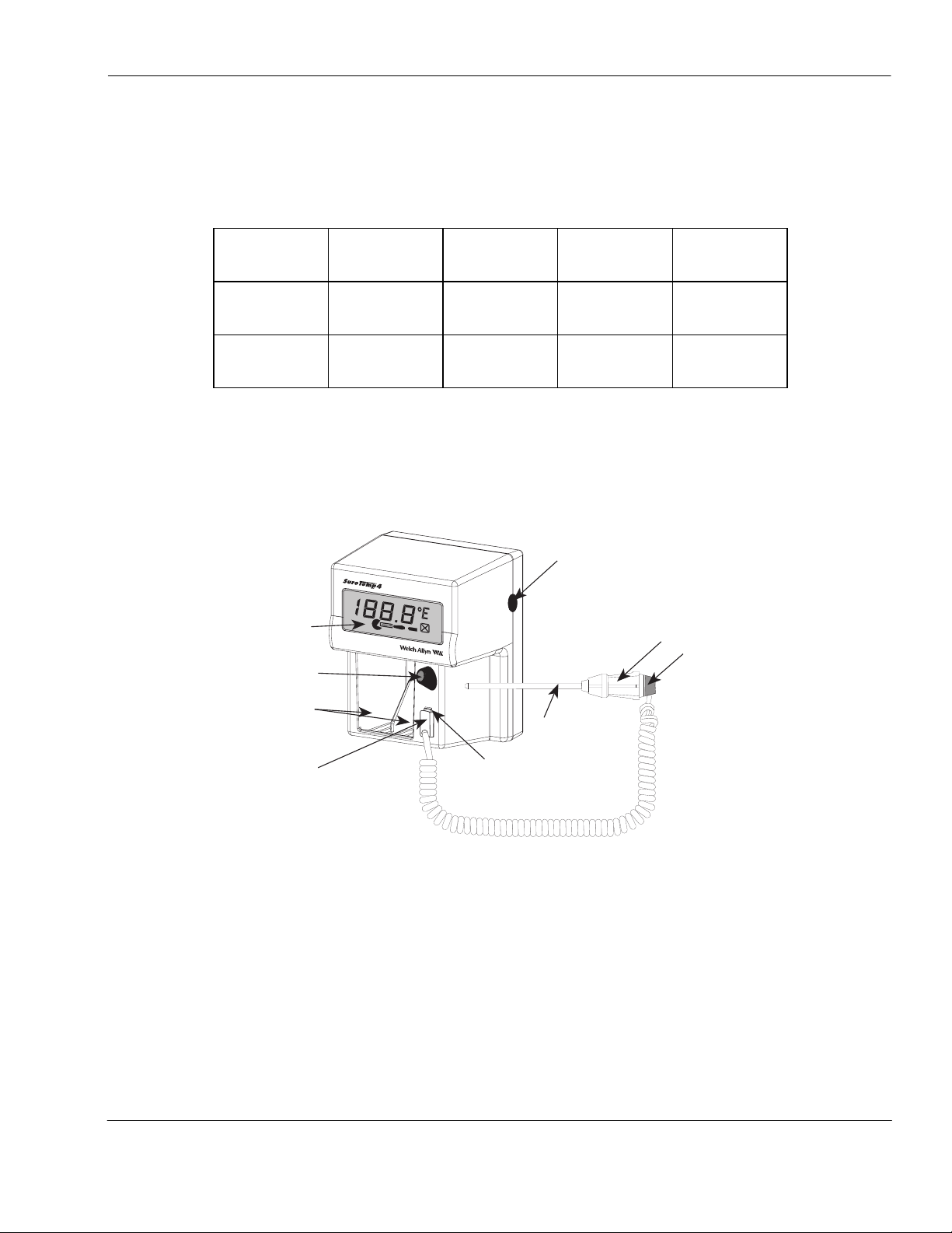
1. Display 6. Probe
2. Probe storage channel 7. Probe handle collar
3. Dual probe cover storage well 8. Ejection button
4. Probe connector receptacle 9. Mode selection button
5. Probe connector receptacle latch
6
5
FIGURE 1 - THERMOMETER DIAGRAM
3
Page 8
Welch Allyn Model 767T
Safety & Warnings
CAUTION: DISCONNECT THE SYSTEM FROM THE MAINS SUPPLY BEFORE CONNECTING
THE 767 SURETEMP 4 THERMOMETER.
USE THE 767 SURETEMP 4 WITH WELCH ALLYN 3.5V 767 SERIES WALL TRANSFORMER
ONLY.
DO NOT USE IN THE PRESENCE OF FLAMMABLE ANESTHETICS.
Caution: Federal (USA) law restricts this device to sale by or on the order of a physician.
In order to obtain accurate and reliable temperature-taking results and ensure patient safety, it is
important that this booklet be read thoroughly prior to using the instrument. If you have any technical
or clinical questions concerning the thermometer’s use and/or care, please contact our Customer
Service Department at (800) 854-2904.
• Single-use disposable probe covers, available from Welch Allyn or Diatek, will limit patient cross-
contamination. The use of any other probe cover or the failure to use a probe cover may produce
temperature errors and will invalidate the instrument’s warranty.
• Oral probes (blue ejection button) are to be used for taking oral and axillary temperatures only.
Rectal probes (red ejection button) are to be used for taking rectal temperatures only. The use of
the wrong probe will produce temperature errors.
• The thermometer case is not waterproof; do not drip fluids onto it.
• Do not use this instrument for any purpose other than that specified in this booklet. Doing so will
invalidate the instrument’s warranty.
• Do not use the thermometer if you notice any signs of damage to the probe or instrument.
Contact our Customer Service Department for immediate assistance.
Setup
1. Install supplied Oral probe or optional Rectal probe by inserting the latching plug on the end of
the coiled cord into plug receptacle on the unit. The plug snaps into place and cannot be
removed without depressing the latch. (Figure 1).
2. Insert probe shaft completely into probe storage channel.
3. Turn on the 767 Wall Transformer.
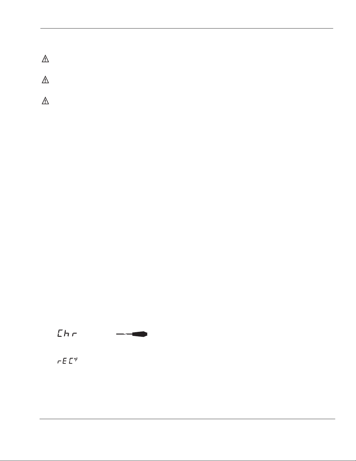
4.
displayed, the thermometer is characterizing the probe. The display will clear when complete.
This process will take from 10 - 70 seconds.
5. Remove the probe from the storage channel.
(blinks) and (steady) are displayed when an oral probe is installed. When
is displayed when a rectal probe is installed.
6. Observe the LCD to see that all display segments appear followed by the display of the probe
type OrL = Oral or rEC = Rectal. Replace probe in storage channel.
7. Insert two boxes of disposable probe covers (part number 05031) into the dual storage well.
4
Page 9

Technical Manual
Changing Probes
• Depress the latch and unplug the probe connector from the thermometer.
• Remove the probe from the storage channel.
• Repeat steps 1 through 6 in the SETUP section.
Normal Mode
Most temperatures are taken in the Normal (predictive) mode. The thermometer automatically resets
to the Normal mode after the probe is returned to the storage channel.
Note:
For Oral probes; if the instrument’s display changes to the probe type display,
the probe cover is loaded, the display will change to°F (without
cover. The instrument is not ready for the probe to be inserted into the patient’s mouth until the
display returns to
The thermometer will switch to Monitor Mode automatically under the following conditions:
1. If the prediction algorithm has not been activated within 30 seconds of withdrawing the probe
from the probe storage channel.
2. If the instrument determines that room temperature is above 33.9°C (93.0°F).
The thermometer reads the probe temperature immediately upon removal of the probe’s shaft
from the storage channel. If the probe is extracted immediately after taking a temperature; it will
not have had sufficient time to cool to room temperature. This will cause the instrument to detect
a false room temperature higher than actual room temperature.
OrL°F
.
OrL
) briefly upon loading of the probe
OrL°F
, before
Monitor Mode
Monitor mode is generally used for long term temperature monitoring, taking axillary temperatures, or
when difficult situations prevent accurate temperatures from being taken in the Normal mode.
When used correctly, the instrument will display the patient’s temperature in about 4 seconds. The
instrument will beep briefly to signal completion of the Normal mode temperature cycle.
If the probe’s shaft is not inserted into the storage channel within 30 seconds of completion of a
Normal mode temperature cycle, the instrument will shut off. Simply replace the probe’s shaft into the
storage channel to prepare for the next temperature.
Note:
The instrument will shut off automatically if the probe temperature remains below 28.9°C
(84.0°F) for more than 5 minutes.
Biotech Mode
Biotech mode provides the ability to query the following information:
1. Display test.
2. Software revision.
3. Internal temperature reference measurement to the nearest 1/100 of a degree Fahrenheit.
5
Page 10

Welch Allyn Model 767T
4. Probe temperature to the nearest 1/100 of a degree Fahrenheit (98.30 will be displayed as 830).
Biotech Mode is entered by the following steps:
Note: While in the Biotech mode, the leading digit and decimal point are suppressed in order for the
instrument to display temperatures at higher resolution (i.e., 98.3 °F will be displayed as 830).
1. Ensure that a probe has been installed.
2. Depress and hold the Mode button for 7 seconds.
3. Observe that the instrument completes its display test. This is the same display test as initiated
when power is first applied. Each segment of the display is individually lit. Following this, all
segments are lit briefly.
4. The instrument will then momentarily display the software revision with the left half of the probe
shaft icon and the probe cover icon (indicating Biotech Mode). The display should show “r X.X”
where “X.X” is the revision number (i.e., r1.5). You will need to know the revision number when
discussing operation with Welch Allyn customer support.
5. A temperature display of the internal-reference-resistor measurement comes next. This reading is
generated by the instrument reading an internal, precision, fixed resistor as if it were a probe. If all
of the A/D conversion electronics are functioning properly, this measurement will produce a
reading between 678°C (36.78°C) and 689°C (36.89°C), or 820°F (98.20°F) and 840°F (98.40°F),
inclusive. Momentarily depressing the Mode button will always toggle the reading between Celsius
and Fahrenheit regardless of the mode.
6. A display of the probe tip temperature can now be obtained by withdrawing the probe from its
holder. The display will be of the same form as the internal-reference-resistor measurement
display (see above).
Note: If the probe is not removed from the probe holder within 1 minute, the unit will exit from the
Biotech Mode.
7. To exit Biotech Mode at any time, put the probe back into its holder. If the probe was never
removed from its holder, pull it out from its holder and then return it to its holder.
If you cannot enter the Biotech mode, refer to the
Troubleshooting
section.
Biotech Mode Problems
section of the
PREVENTATIVE MAINTENANCE
The following suggested preventative maintenance is recommended to maximize uninterrupted
service on the Model 767 SureTemp 4 Thermometer
Units which are in service on a regular basis should have the following preventative maintenance
performed every 6 months:
1. Visually inspect the thermometer for physical damage which might cause future product failure.
2. Clean the unit per instructions in your Directions for Use manual supplied with the thermometer
and/or per the instructions below.
6
Page 11

Technical Manual
3. Perform the power up display test, startup display test and Model 9600 Calibration Testing
procedure found in the Model 9600 Operation Manual. Perform calibration adjustment if
determined necessary by following the procedure in this manual.
Cleaning and Sterilization
Routine Cleaning
Refer to the Directions for Use for routine cleaning
ETO Gas Sterilization Procedure
When no other form of decontamination such as a germicidal wipe is acceptable, a low temperature,
(not to exceed 48.9°C (120°F)) ETO gas sterilization cycle may be used. Refer to your institution’s
standard operating procedure for the length of the cycle.
This type of sterilization may cause some hazing of glossy plastic surfaces and should be used only
when absolutely necessary.
1. Disconnect the Model 767 Thermometer from the power supply.
2. Ensure that the probe is removed from its storage channel and disconnected from the instrument.
3. Remove any probe covers from the probe cover storage well
4. Wrap the thermometer in a standard sterilization type packaging such as a Baxter Tower Dualpeel
Sterilization Pouch.
5. ETO gas sterilize at a temperature not to exceed 48.9°C (120°F) and aerate.
6. Remove the sterilization packaging.
7. Before applying power, allow the probe and instrument to stabilize to room temperature for
at least
one hour.
8. Verify proper calibration of the thermometer and probe using the Welch Allyn Model 9600
Calibration Tester.
CALIBRATION TESTING
Calibration Key Procedure
Unplug the probe from the thermometer. Insert the Calibration Key into the probe connector
receptacle on the thermometer. Remove the probe shaft from the probe storage channel to initiate a
temperature taking cycle. Wait for the display test and then observe the display. The display must
read between 97.1°F and 97.5°F inclusive for the calibration of the instrument to be correct. Remove
the Calibration Key and reinstall the probe connector plug. Then install the probe into the probe
storage channel. (This will initiate a probe characterization cycle.)
Note:
This Cal Key test does not test the calibration of the probe. To do so requires the use of the
Welch Allyn Model 9600 Calibration Tester.
7
Page 12

Welch Allyn Model 767T
If the reading from the Cal Key is not within the specified range or you are having other problems with
the use of the Cal Key, refer to the
Cal Key Problems
section of the
Troubleshooting
section.
M9600 Procedure
The M9600 Calibration Tester provides a convenient means of testing the entire thermometer system
(instrument and probe). The 9600 must be warmed up and stable at one of the two available
temperature settings. The thermistor based instrument under test must be in Monitor mode and no
probe cover loaded. The probe is inserted into the small hole in the dry heat well of the 9600 and
allowed to settle to the final temperature. The reading on the thermometer must be within the range
specified on the 9600. Refer to the M9600 Operation Manual for complete instructions.
Note:
All Welch Allyn thermometers (thermistor and infrared ear thermometers can be checked in the
M9600.)
If you are having problems with the use of the M9600, refer to the Troubleshooting section in the
M9600 Operation Manual.
THEORY OF OPERATION
Technical Overview
The heart of the Model 767 Thermometer is comprised of two custom integrated circuits, a standard
microcontroller, and an LCD driver which provide most of the microprocessor and analog circuit
functions. All control functions are governed by the Motorola MC68HC11D0 microcontroller (U1) and
a memory/IO chip (U2). All analog interfacing to the microprocessor, probe, horn, self-calibration
circuit, and backlight is provided by U4, and the LCD is controlled by U5.
Probe resistance measurements are made by measuring pulse widths which are generated by
sequentially switching in two calibration resistors and the probe thermistor, one at a time. These pulse
widths are measured by the microcontroller which calculates the probe resistance. The actual probe
temperature is then calculated from the probe resistance.
Probe Enhancements
The Model 767 Thermometer has the capability to detect probe type - Oral vs. Rectal. This allows the
oral temperatures to be as fast as possible (4 seconds) by using different operating modes based on
probe type. Rectal probes give a Normal mode temperature in about 15 seconds. Probe type
recognition also allows the use of minor differences in prediction parameters tailored to the
temperature taking site to help increase speed over most previous products.
The probe type is configured for thermometer recognition by connecting the appropriate combination
of probe connector contacts to ground within the probe assembly connector.
In addition to the probe type enhancements, Model 767 Thermometer probes have been improved for
thermal time constant (speed of response).
Model 767 Thermometer Oral probes incorporate a warming resistor in the tip to pre-warm the probe
before placement in the mouth thus speeding response even further.
8
Page 13

Technical Manual
Probe Switch
The probe switch (S2) is activated by the probe shaft when the probe is installed or removed from its
storage channel. Placing the probe into the channel, pulls U1-29 high via R27. When the probe is
withdrawn, this line is pulled low. This signal is also routed to test connector J3A, pin 7, to allow
automated testing of this function during factory test. R27 allows this line to be pulled high or low at
J3A during factory test regardless of the actual switch position.
HINT/CAUTION: For the technician, J3A serves as a convenient set of “test points” to monitor proper
operation of all user switch functions, BUT BE CAREFUL WITH STATIC DISCHARGE! J3A TIES
DIRECTLY TO CMOS PROCESSOR INPUTS WHICH ARE EASILY DAMAGED BY STATIC
DISCHARGE. FOLLOW PROPER HANDLING TECHNIQUES.
rs_232_pwr
FACTORY
TEST
SYSTEM
CONNECTOR
PROBE
HORN
PROBE
HEATER
BACKLIGHT
_clear_to_send
RxD
TxD
_request_to_send
probe_1
probe_0
horn_on
_heater_Q
_heater_C
_heater_tst
_heater_pwr
backlight_pwr
MC68HC11D0
MICROCONTROLLER
SYSTEM
_mode_button
_probe_sw
sda
scl
MODE BUTTON
PROBE SWITCH
LCD DISPLAY
PULSE WIDTH
A/D
CONVERTOR
ad_power
_ad_trigger
probe_ad_select
ptb_ad_select
hical_ad_select
local_ad_select
ad_out
7.37 MHZ
CRYSTAL
9
Page 14

Welch Allyn Model 767T
FIGURE 2 - SYSTEM BLOCK DIAGRAM
Monitor Mode
The Monitor mode is selected manually by the Mode button (S1) on the right side of the instrument.
This button, when pressed, ties U1-30 low. When this line (*DMODE) is held low for more than two
seconds with the probe’s shaft withdrawn from its holder, the thermometer enters Monitor mode.
*DMODE is routed to the test connector (J3A-10) to allow automated testing of this function during
factory test
The actual probe temperature, as determined by the A/D conversion electronics, appears directly on
the liquid crystal display which is driven by the LCD driver (U5). See the
and Display
The displayed temperature range (for any mode) is limited to 28.9°C to 42.2°C (84.0°F to 108.0°F).
section for a description of the A/D operation.
Temperature Measurement
Normal Mode
The Oral probe is pre-warmed using a pulse width modulation (PWM) controller to 33.9°C (93°F) upon
extraction from the storage channel. When the probe is first extracted and colder than 33.9°C, the
pulse widths are at a maximum percentage ON vs. OFF to warm the probe quickly. When the probe
reaches 33.9°C, the pulse widths narrow to a duty cycle just enough to maintain temperature. When
the probe is placed in the mouth, the heat supplied by the mouth makes the pulse widths reduce to
zero. This reduction to zero (and the probe being at least up to 33.1°C) triggers the start of the
prediction algorithm.
The shape of the rising temperature curve is monitored and the best fit to a curve is found. When the
curve fit is stable, the final predicted temperature is displayed.
If the prediction criteria explained above are not met within 15 seconds of starting the prediction
process, it will automatically switch to Monitor mode.
If the ambient temperature is above 33.9°C (93.0°F) the unit will automatically switch to Monitor mode.
Rectal probes are not prewarmed. The shape of the rising temperature curve is monitored and a
continuously computed correction factor is added to the actual probe temperature. The temperature
cycle is terminated and the temperature is displayed when the predicted temperature remains stable.
If the thermometer does not detect a rise of two degrees above ambient within 30 seconds of
removing the probe from its holder, it will automatically switch to Monitor mode.
Power Supply
Power is drawn from an 8VAC power supply. This AC voltage is converted to DC by a full wave
bridge rectifier (D1, D2, D7, and D8), regulated by a low dropout 5 volt regulator (U3), and filtered by
capacitors (C3, C4, C5, C16, and C17). The regulated voltage will range from about 4.75 volts to 5.25
volts DC. This +5VDC (Vdd) is further filtered to create an analog 5 volt branch (+5VA).
10
Page 15

Technical Manual
Microcontroller I/O Assignments
The following table depicts the input/output assignments for the microcontroller, with “active low”
signals prefixed with an underscore (refer to schematic and block diagram):
MC68HC11D0 Input/Output Assignments
Signal Name Port In/Out Pin Number
R/_W PD7, R/_W Out 12
AS PD6, AS Out 13
_wake_up _IRQ In 15
RxD PD0, RxD In 16
TxD PD1, TxD Out 17
MISO PD2, MISO In 18
sda PD3, MOSI Out 19
scl PD4, SCK Out 20
backlight_pwr PD5 Out 21
_heater_C PA7 Out 23
_heater_Q PA6 Out 24
_request_to_send PA5 Out 25
horn_on PA4 Out 26
_clear_to_send PA3 In 27
ad_out PA2, IC1 In 28
_probe_sw PA1 In 29
_mode_button PA0 In 30
11
Page 16

Welch Allyn Model 767T
Memory/IO Input/Output Assignments
The following table depicts the input/output assignments for the PSD311L peripheral, with “active low”
signals prefixed with an underscore (refer to attached schematic and block diagram):
PSD311L Peripheral Input/Output Assignments
Signal Name Port In/Out Pin Number
probe_1 PB7 In 4
probe_0 PB6 In 5
not used PB5 Out 6
rs_232_pwr PB4 Out 7
probe_out PB3 Out 8
probe_in PB2 Out 9
_heater_tst PB1 In 10
_heater_pwr PB0 In 11
_ad_trigger PA7 Out 14
ad_power PA6 Out 15
probe_ad_select PA5 Out 16
ptb_ad_select PA4 Out 17
hical_ad_select PA3 Out 18
local_ad_select PA2 Out 19
_batt_ad_select PA1 Out 20
not used PA0 Out 21
not used PC0 Out 40
not used PC1 Out 41
not used PC2 Out 42
NOTE: All unused I/O pins are set to output.
12
Page 17

Technical Manual
IIC Interface to LCD Display Driver
The display driver utilizes an IIC serial interface. Each write to the display (signals
begin with the following four command bytes followed by up to eight data bytes: 70H (device type),
e0H (device select), c8H (device mode), 18H through 26H (LCD driver RAM start address).
externally tied to
sda
to allow a read of the IIC acknowledge as required.
sda
and
scl
) must
MISO
is
With all LCD segments activated, the 767T display appears as shown in
not found.
ram addresses and the corresponding LCD segment, which provide visual enunciators to display
status and/or alarm indications as follows:
• “Instrument Malfunction” icon consists of a square box with an X within it, (segments 28-33), which
indicates that the unit has detected an internal malfunction or the unit is unable to make an
accurate determination due to a failure of the unit’s internal circuitry;
• “Up - Down Arrows” indicate that the patient temperature is above 108o F (42.2 o C), or below 84
F (28.9 o C) respectively. The up arrow is formed by displaying the bottom half of the X,
(segment 30), plus the bottom side of the square box; (segment 33), the down arrow is formed by
displaying the upper half of the X, (segment 32), plus the top side of the square box; (segment
28),
• “Broken Probe” icon consists of a probe silhouette where the distal half of the probe shaft,
(segment 36), and the probe body, (segment 35) are flashed. This icon is displayed whenever the
unit is active and a malfunction within the temperature probe has been detected;
• “Probe Position” icon consists of the “PacMan” open mouth silhouette, (segment 38), and the
probe silhouette, (segments 35, and 36), lit to inform the user of improper probe placement into
the mouth;
• “Monitor Mode” icon consists of a capital “M” formed out of the left and right sides of the square
box, (segments 31 and 29), and the upper half of the X, (segment 32); it is displayed whenever
the unit is active and in Monitor Mode;
Error! Reference source not found.
.
also includes the interface between the LCD driver
Error! Reference source
o
• “Fahrenheit/Celsius” icon is indicated by displaying either a “F”, (segments 25 and 26), or a “C”,
(segments 25 and 27), respectively to indicate the units of the displayed temperature.
• Bio Tech mode icon consists of the distal half of the probe shaft, (segment 36), and the probe
cover, (segment 37). It is displayed whenever the unit is in Bio Tech Mode.
13
Page 18

Welch Allyn Model 767T
•
24
2
7
1
6
1
3
8
4
5
38
9
14
13
37
10
15
11
12
36
16
17
22
21
18
23
19
20
3435
25
25
26
25
27
28
32
31 29
33
30
•
DRIVER
ADDRESS
Bit
7
Bit
6
Bit
5
Bit
4
Bit
3
Bit
2
Bit
1
Bit
0
24 - 25 -------34
26 - 27 -------1
28 - 29 786523430 - 31 14 15 13 12 9 10 11 16
32 - 33 22 23 21 20 17 18 19 34 - 35 ----24252726
36 - 37 30 33 - 29 31 32 - 28
38 - 39 ----35363738
FIGURE 3 - LCD DISPLAY
Reset/Self Tests
Upon power-up, the microcontroller and memory/IO chips (U1 and U2) receive a power-up reset
signal from the components associated with the reset line (U1-14 and U2-3). During power dropout,
the voltage regulator, U3, generates a reset signal. When *RST goes high, C7 is charged slowly
through R13 providing a slow rise reset to the microcontroller and memory/IO chips.
The delay between power-up and the beginning of *RST rise is determined by C1.
When the reset signal is complete, the microcontroller and memory/IO chips launch a series of self
checks which include RAM test, ROM test, EEPROM test, instruction set test, self calibration tests
(PTB test, hi cal, low cal), probe warmer circuitry tests, probe test, and ambient temperature test. Any
failures here will cause a specific error code to be displayed to assist debugging.
14
Page 19

Technical Manual
Microprocessor Clock
The clock for the processor is generated by X1. This is a single 3 pin ceramic resonator with internal
capacitors running at 7.3828 MHz. The microcontroller, U1, drives this component into oscillation by
incorporating an internal inverter.
Temperature Measurement and Display
The thermometer uses probes which incorporate negative temperature coefficient thermistors. When
the temperature of the probe is increased, its electrical resistance decreases. Earlier products (M600,
M650) use “10K” thermistors which means that, at room temperature (25°C), their value is
approximately 10 Kohms. Model 767 Thermometer probes use “20K” thermistors so they are
approximately 20 Kohms at room temperature. At 37°C (patient temperatures) they are near 12
Kohms. The change in resistance is nonlinear with temperature and an equation describing this curve
is programmed into the thermometer.
The thermometer contains three high precision calibration resistors (0.1% tolerance) R20, R21 and
R23. Their values are programmed into the instrument so that A/D conversions from these can be
done to “calibrate” the electronics. This allows results from the unknown probe resistance to be
compared to the known resistance’s. These three resistors are referred to as “hi cal”, “low cal” and
“PTB” resistors. They are equivalent to temperatures in that if the probe were at a high temperature
41.6°C (106.8°F), its resistance would equal the hi cal resistor value. Similarly if the probe were at a
low temperature 33.8°C (92.9°F) its resistance would equal the low cal resistor value. The PTB
resistor is in the middle of the range and equivalent to 36.8°C (98.3°F). Use of these resistors in the
A/D process allows the probe resistance readings to be “ratioed” against known resistance readings
and thus “absolute” readings, which can be affected by drift in the electronics due to aging and
temperature, are eliminated.
The actual A/D conversion consists of converting resistance to a timed pulse width. The components
involved are C6 (the timing capacitor), Q7 (the constant current transistor), any one of R20, R21, R23
or the actual probe resistance, and the associated FET transistors Q3, Q5, Q6, or Q8.
Due to U4 design, on power up R24 and R26 bootstrap U4 to begin the charge of C6. Once a small
voltage is developed on C6, U4 takes over and maintains C6 at 2.4 volts via pin 7 of U4. When an
A/D conversion is to start, prior to the trigger from the processor, it turns on one of the four FETs.
This establishes a constant current through the associated resistor. The current flowing is supplied
from U4 pin 7 while maintaining its voltage at 2.4 volts. Throughout the A/D process, U4 pin 4 is held
at 1.2 volts. This means that while current is flowing through Q7, its emitter sits at 0.6 volts. Since this
is a constant voltage, the current through the selected resistor and FET is also constant. The next
event is to trigger the start of the pulse measurement which occurs via processor control into U4 pin 5.
This makes U4 pin seven go to high impedance ending its supply of current for the selected resistor.
Therefore current must now be supplied by C6. Since it is still a constant current situation, C6
discharges linearly with time. Its voltage is monitored by an internal comparator in U1 and when it
drops to 1.2 volts the A/D OUT line (U4 pin 2) goes active stopping the timer in the processor. The
constant current value is inversely proportional to the resistance value selected so that small
resistance values produce high currents and therefore fast discharges. Since small resistance’s are
related to high temperatures, short pulse widths are also related to high temperatures. L3 is in series
with the discharge current but constitutes a very small constant DC resistance so it has no effect on
results. Its only purpose is for RFI suppression. C9, C10, C11, and C12 are also only for RFI, and
ESD purposes.
15
Page 20

Welch Allyn Model 767T
In Monitor mode a calibration cycle, where each of the fixed resistors is measured by the A/D function,
is performed once every second. In Normal mode a calibration cycle is performed once at the
beginning of the temperature prediction process.
A/D Power Control
When A/D conversions are not needed, power is saved by shutting down U4 via the A/DPWR line on
U2 pin 15. R22 serves as a current limiting resistor and establishes the low power draw for U4’s
internal current sources.
This A/DPWR line is also routed to R9 and R12 for probe detection. This provides a power saving
function so supply current is not drawn through these resistors when probe detection is complete.
Additionally, A/DPWR is routed to U5-5 to supply the LCD driver with power. This provides a power
saving function in that power is not drawn by the LDC driver nor LCD when not needed.
Probe Detection
Upon power-on reset or when a new probe is first installed, the thermometer performs a probe
initialization process. Probe type is first detected and then if it is an Oral probe, its warming
characteristics are determined. No Rectal probes are warmed, so warming characteristics are not
tested in either instrument on these probes.
When the probe connector is removed, U2 pins 4 and 5 are pulled high by R9 and R12, and a “no
probe” logic is detected. Upon determining that the probe has been removed, a software flag is set in
RAM indicating the probe has been removed. (RAM contents are not lost when the processor “goes
to sleep.”) With no probe installed, the unit goes to sleep and turns off the clock and the A/D power
line to save battery power.
Probe connector installation does not wake the instrument up. When the probe shaft is stowed, the
probe switch places voltage on U1 pin 29 via R27. This alerts the microcontroller which then reads
the RAM flag and sees that the probe logic lines are indicating a probe is connected. This situation
triggers a probe characterization routine as described in the Probe Warming section.
The probe type is determined by the probe logic lines at J1-C and F. Oral probes pull both lines low.
Rectal probes pull only J1-C low.
Probe Warming
Probe characteristics vary somewhat due to normal production process variations and it is desirable to
warm the probe as efficiently as possible from a time--to--ready standpoint and from a temperature
stability standpoint when the probe is up to temperature.
The probe warming process is a closed loop feedback control system incorporating PWM (pulse width
modulation) control. To establish proper control parameters, the probe under control must be
characterized.
The probe temperature is read once every 200 mS until the temperature is found to be not changing.
16
Page 21

Technical Manual
Once a stable temperature is determined a 200 mS test pulse of power is applied to the probe via the
warming circuitry. The probe temperature change resulting from this pulse is used to determine
parameters needed for the PWM algorithm. This completes the probe characterization process.
The warming circuitry consists of Q2, Q4, Q10, R8, R15, R16, R18, R25, R28, C14, C15, C202, D6,
L1 and the resistance in the probe connected to J1-B and J1-E. Power is applied to the probe
connection only when both Q2 and Q9 are turned on. When this occurs, both feedback lines to the
processor (U2 pins 10 and 11) are pulled high indicating proper operation. A fail safe hardware shut
off circuit is incorporated consisting of C14, D6, Q10 and R25. This circuit will shut off power to the
probe if the software fails to refresh this circuit. This prevents overheating due to any software errors
leaving the warmer circuit on continuously.
At the start of a warming pulse, the processor drives both warmer control lines (U1-23 and U1-24) low.
This turns on all three transistors Q2, Q9 and Q10. Q10 is turned on because the voltage across
capacitor C14 cannot change instantly. Its positive side goes low when its negative side is pulled low
by the processor. Since Q9 E and B are pulled near the positive rail and Q8 B and E are pulled near
the negative rail, the base current from Q9 flows through R28 and mostly into Q10, but some current
flows through R25 to satisfy the diode drop across Q10 E to B. This current and Q10 base current
flow into C14 charging it. As it charges, the voltage rise eventually shuts off Q9.
This hardware shut off is only allowed to progress to completion during factory test and each time an
Oral probe is installed as part of the instrument self test process. The thermometer checks that the
hardware shut off has occurred within one second of turn on.
Normal probe warming is controlled by the software and if the probe is well below the control
temperature of 33.9°C (93°F) the pulse widths are at a maximum. Every 100 mS the hardware shutoff
circuit is refreshed by the processor driving its pin 54 high briefly. This momentarily shuts off power to
the probe while discharging C14 into the positive supply through D6.
Once the probe has been brought near 33.9°C (93°F), the pulse widths are reduced to maintain this
temperature. This is when the display switches from the all segments display test to “OrL” indicating
that the unit is ready for placement in the mouth.
R8 and R18 in combination with R16 serve as pull down resistors ensuring that the processor
feedback lines (U2 pins 10 and 11) go low immediately upon warmer component shut off. L1, and
C15, and C202 serve as RFI suppression components.
Liquid Crystal Display
The LCD has 7 backplane lines (DS1 pins 1-7) and 12 segment lines (DS1 pins 8-19). The LCD fluid
thresholds require a regulated set of voltages at 1.2, 2.4, and 3.6 volts. These voltages are set by the
voltage that appears on U5-12 (0VDC) and are supplied to the LCD by the display driver (U5
The LCD glass is electrically tied to the display PCB via two elastomeric connectors sandwiched and
compressed between the glass and the PCB by the 8 display retaining screws.
Backlight (Optional)
The backlight is an Electroluminescent style flat panel lamp residing directly under the LCD.
An oscillator is required to convert battery DC voltage to an AC voltage of about 80 volts and 300 Hz.
17
Page 22

Welch Allyn Model 767T
Whenever anything is being displayed, the microcontroller outputs a high to U4-12. U4 then outputs a
low at pin 13, which is sent out to the backlight oscillator on the Display PCA via J2B-5. Vdd is also
supplied to the oscillator via J2B-1. The oscillator consists of Q101, Q102, C102, R106, R107, D101,
T1, and the lamp itself (DS2). R14 acts as a pull up to return this line high when not in use
Horn
The horn is activated at the start of a temperature taking cycle, at the end of a Normal mode
temperature cycle, and for various error conditions.
A short duration high pitch single beep is indicative of normal operation. A short duration double beep
is used to indicate errors.
The horn is a piezoelectric ceramic resonator driven by a processor square wave buffered through U4.
The horn control signal comes from U1-26 and enters U4-3 where it is buffered and inverted and sent
out on pin 1 directly to the horn LS1. R5 is used to limit the current applied to U4-3.
F/C Switching
When momentarily (less than 2 seconds) depressing the Mode button (S1), U1-30 goes low. The
microcontroller then toggles the display from F to C or C to F. This line is also run to the test
connector J3A-10 to allow automated testing of this function during factory test.
ERROR CODES
Error codes fall into three categories. Transitory, Recoverable and Non-Recoverable.
Transitory errors are generated by external events and are not errors generated by the thermometer.
They do require that temperature measuring be inhibited until the error is cleared. There is no limit to
the number of times a transitory error can occur. All probe problems are considered by the
thermometer to be external events and are therefore classified as transitory.
Recoverable errors are generated from internal test failures which are non-catastrophic and require
that temperature measuring be inhibited until the error is cleared. A recoverable error will be
promoted to a non-recoverable error if it occurs 4 times sequentially. After displaying the error code
and any appropriate icon, the instrument will reset itself and attempt to resume normal operation.
After the fourth attempt to clear itself, the error becomes non-recoverable.
Non-recoverable errors are generated from internal test failures that are catastrophic (or from
promoted recoverable errors). The error code and any appropriate icon will be displayed along with
the “[X]” Instrument Malfunction icon.
The only way to continue at this point is to reset the electronics by cycling power.
NOTE: The error codes E1.0, E2.1, E2.3, E3.0, and E4.1 can sometimes be caused by a faulty
probe. It is advisable to remove probe completely from instrument and check functionality as
described in the Setup section before assuming an instrument problem instead of a probe problem. If
another probe is available, this can prove useful in tracking down the source of the problem.
18
Page 23

Error Code Table - Software Version R1.7 and above
NUMBER ERROR TYPE DESCRIPTION
System Hardware/Software Errors
E0.1 NON-RECOVER Internal RAM read/write test failed
E0.2 NON-RECOVER Internal ROM check sum failed
E0.3 NON-RECOVER CPU instruction error
E0.9 NON-RECOVER Fatal Software Errors
System Transitory Errors
E1.0 TRANSITORY Outside ambient operating temperature range
C1.1 TRANSITORY Probe characterization stability time out
E1.2 TRANSITORY Probe broken or missing
E1.3 TRANSITORY Transmit buffer overflow (transmit only, no display)
A/D Converter Errors
E2.0 RECOVERABLE Low cal. resistor pulse width error
E2.1 RECOVERABLE Hi cal. resistor pulse width error
E2.2 RECOVERABLE PTB resistor pulse width error
E2.3 RECOVERABLE Probe pulse width error
System Functional Errors
E3.0 RECOVERABLE PTB test error
Math Errors
E4.0 RECOVERABLE Log of zero is undefined
Heater and Probe Errors
E5.0 RECOVERABLE Heater fail safe time out error
E5.1 RECOVERABLE Heater circuit failure
E5.2 RECOVERABLE Heater overheated
E5.3 RECOVERABLE Heater watch dog time out
E5.4 RECOVERABLE StartHeater initial pulse too large
Technical Manual
Error Code Table - Software Version R1.6 and below
NUMBER ERROR TYPE DESCRIPTION
System Hardware/Software Errors
E0.1 NON-RECOVER Internal RAM read/write test failed
E0.2 NON-RECOVER Internal ROM check sum failed
E0.3 NON-RECOVER CPU instruction error
E0.9 NON-RECOVER Fatal Software Errors
System Transitory Errors
E1.0 TRANSITORY Outside ambient operating temperature range
C1.1 TRANSITORY Probe characterization stability time out
E1.2 TRANSITORY Probe broken or missing
E1.3 TRANSITORY Transmit buffer overflow (transmit only, no display)
19
Page 24

Welch Allyn Model 767T
Error Code Table - Software Version R1.6 and below (continued)
A/D Converter Errors
E2.0 RECOVERABLE Low cal. resistor pulse width error
E2.1 RECOVERABLE Hi cal. resistor pulse width error
E2.2 RECOVERABLE PTB resistor pulse width error
E2.3 RECOVERABLE Probe pulse width error
System Functional Errors
E3.0 RECOVERABLE PTB test error
Math Errors
E4.0 RECOVERABLE Log of zero is undefined
Heater and Probe Errors
E5.0 RECOVERABLE Q heater transistor failure
E5.1 RECOVERABLE C heater transistor failure
E5.2 RECOVERABLE Heater fail safe time out error
E5.3 RECOVERABLE Heater circuit failure
E5.4 RECOVERABLE Heater overheated
E5.5 RECOVERABLE Heater watch dog time out
E5.6 RECOVERABLE StartHeater initial pulse too large
TROUBLESHOOTING
All thermometer operational parameters can be tested for proper operation without the unit being
taken apart and without the need for any tools. Refer to the
in particular to the
Setup
Biotech Mode
and
sections for guidance on preliminary checks.
If the trouble seems to be calibration related, refer to the
Operational Characteristics
Calibration Testing
section.
section and
If these sections do not prove useful in resolving the problem and you are sure that the instrument is
not performing properly, the following sections should guide you through the debugging process,
given the proper tools and equipment.
Equipment Required
Most operations can be performed with standard tools and meters. A 4” long Torx, T-8, driver is
needed for most screws. A #1 Phillips screwdriver is needed for the probe switch screws.
A standard lab 3.5 digit digital multi-meter (DMM) will provide sufficient accuracy for a host of tests. A
needle tipped pair of probes is recommended.
For particularly difficult tasks, a digital storage oscilloscope is sometimes the only way to analyze high
speed signals, but is not generally required.
Standard electronics tools and supplies for small surface mounted and through hole component
rework will be needed to perform any electronics repairs. Some surface mounted components are
extremely small and present a challenge for rework by hand. A light touch, tweezers, sharp soldering
iron tip and low heat (#7 tip) is recommended.
A Model 767 Wall Transformer is recommended for use as a power supply. Power and ground are
available at J5-C and J5-D, respectively.
20
Page 25

Technical Manual
Terminology
Many standard abbreviations are used in this section (and elsewhere):
PCB printed circuit board (the board itself) LCD PCB PCB holding the display assembly
PCA printed circuit assembly (the board with all its
components)
Main PCB large PCB holding the microprocessor O-Scope Oscilloscope
LCD Liquid Crystal Display
Component Reference Designators:
C capacitor Q transistor
D diode R resistor
E test point S switch
J connector jack T transformer
L inductor U integrated circuit
P connector plug X crystal, resonator
DMM Digital Multi-Meter
21
Page 26

Welch Allyn Model 767T
Troubleshooting Table
SYMPTOM POSSIBLE CAUSE PROCEDURE
No operation No power to unit Make sure its power supply is plugged in and turned on. Make
sure the power supply is providing between 5.9 and 10 Volts
AC. Make sure the power contacts are making contact with
the power supply.
Short circuit. The resistance at the power input contacts (J5-A and J5-B)
should be at least 3MΩ. If it is less than this, check the power
circuit for shorts.
The resistance across the 5VDC test points (J5-C and J5-D)
should be at least 20kΩ. If it is less than this, desolder the
display electronics and check it again. If the resistance goes
up, suspect a short on the display board. If the resistance did
not go up upon desoldering the display board, check everything
but the power electronics on the main board for shorts.
Display
problems
Power circuit
component malfunction
Failed component. Check oscillator at U1-44 for 7.38 MHz sine wave. If not
LCD PCB loose. Check that all 8 Torx screws holding the Display PCA to the
Dirty, or crooked
elastomeric LCD
conductor (zebra)
strips. Crooked zebra
strip
Broken/shorted flex
strip cable.
With power turned on, measure 5.0 VDC +\-5% across J5-C
and J5-D (Gnd). If too low, lift J3-3 and check voltage between
here and J5-D. If still too low, suspect U3. Check for a DC
voltage of about 12 VDC at U3-1. If this is below 5.5VDC or is
very unstable, suspect the filter capacitors (C1, C3, and C18
for low voltage), or rectifier diodes (D1, D2, D7, and D8 for
unstable voltage).
present, suspect X1, R1, or U1.
Display housing are tight.
Remove Display PCA by opening the case and unscrewing the
8 Torx screws on the Display PCA. Clean LCD elastomeric
strips, LCD glass contacts, and PCB contacts with lint proof
cloth dampened with alcohol. Check that the EL panel is not
overlapping the black, Carbon ink covered zebra pads on the
display PCB.
Check continuity of all 6 lines. Assure continuity with flexing of
strip.
22
Check for shorts between adjacent lines at both ends.
Page 27

Troubleshooting Table (continued)
SYMPTOM POSSIBLE CAUSE PROCEDURE
Technical Manual
Display
problems
(continued)
Dark blotches
near the
bottom of the
display
Failed component in
LCD driver circuit.
Cracked LCD. Inspect LCD for hairline cracks especially in corners.
Short circuit or open
LCD lines.
Microprocessor failure
(U1).
Memory/IO chip failure
(U2)
Moisture between
display window and
LCD glass. Display
screws too tight.
Check that data and clock signals on U5-1 and U5-2 are
toggling between 0 and 5 volts immediately after power up or
after pressing and releasing the Mode button.
Check continuity from LCD driver (U5) through to LCD pads.
Check for shorts between adjacent U5 pins. Check for
continuity from U1-19 and U1-20 to U5-1 and U5-2,
respectively.
Check for improper soldering of pins, crystal operation on Oscope, proper reset.
Check for improper soldering of pins, crystal operation on Oscope, proper reset.
Remove, clean, and reassemble the LCD. Tighten screws
starting from the upper right tooling hole (looking in the back of
the display housing, and continuing counterclockwise.
No beeper
sound
Broken horn wire Inspect horn wires for proper soldering
Defective horn Replace horn
Broken connection Check continuity from U1-26 to U4 3. From U4-1 to red
horn wire. From U4-14 to black horn wire. From U4-3 to
blue wire and R5. From R5 to U1-26.
Defective U4 Replace U4.
Defective U1 Check for a logic high on U1-26 when horn should be on.
If not, replace U1.
23
Page 28

Welch Allyn Model 767T
Troubleshooting Table (continued)
SYMPTOM POSSIBLE CAUSE PROCEDURE
No Backlight
(Backlight is
an Option)
Recalled
temperature
incorrect.
F/C
switching
problems
Broken trace. Check U1-21 and U4-12 for proper signal level (+5V
when LCD is on. U4-13 and the cathode of D101 should
be low when the LCD is on. With backlight off, all of the
oscillator parts (Q101, Q102, R106, R107, C102 and
T1(primary) should be at +5VDC.
Defective
Component
Check U1-21 and U4-12 for proper signal level (+5V
when LCD is on). U4-13 and the cathode of D101
should be low when the LCD is on. With backlight off, all
of the oscillator parts (Q101, Q102, R106, R107, C102
and T1(primary) should be at +5VDC.
Power cycled. On power-up, the last stored temperature is replaced
with 98.6
Defective Mode
switch
Check J3A-10 for proper switch function. Line should go
low only while Mode button is depressed.
o
F.
Broken trace Check U1-30 for proper switch function.
Probe:
Wrong type
displayed.
Probe:
Plugged in
but no
display
24
Missing A/D power to
R9 and/or R12
With no probe installed, check that probe connector pins
J1-C and F are both pulled high when any function is
active (recall)
Incorrect wiring of
probe
Oral probes should have a short between pins C, E and
F. (refer to J1 designators on instrument PCB for probe
pin definition.)
Rectal probes should have a short between pins C and E
but open between pins F and C or E.
Bad probe. Replace probe.
Probe not
characterized
A new probe must be installed and left in the storage
channel until the display goes blank. If probe is
extracted during characterization, display goes blank and
operation is halted.
Page 29

Troubleshooting Table (continued)
SYMPTOM POSSIBLE CAUSE PROCEDURE
Technical Manual
Normal/
Monitor
Mode
switching
problems
Cannot enter
Biotech
Mode
Ambient above
33.9°C (93.0°F)
Switched to Monitor
mode before probe
in mouth.
Defective switch Check J3A-10 for proper Mode switch function.
Insufficient Mode
button depression
time
No probe installed A probe must be plugged into the instrument with its
Causes auto switch to Monitor mode.
If 30 seconds pass after ready in Normal mode, unit
switches to Monitor mode.
If probe is still cooling from a previous temperature and
used immediately, it might sense ambient to be above
33.9°C (93.0°F).
Check U1-30 for proper switch function.
Press and hold the Mode button for at least 2 seconds.
shaft fully inserted into the probe holder.
Cal Key
doesn’t
activate
thermometer
Cal Key
shows OrL,
rEC, or ALy
Failed component,
broken trace.
Probe switch not
activated.
Defective Cal Key Replace Cal Key
Check proper switch operation. Refer to F/C, Mode, and
Recall switch troubleshooting.
Model 767 Thermometers need the probe switch
activated before they will start. Place a probe shaft in
the storage channel, then remove it to start Cal Key
measurement.
25
Page 30

Welch Allyn Model 767T
Troubleshooting Table (continued)
SYMPTOM POSSIBLE CAUSE PROCEDURE
Cal Key
shows only
“°F”.
Monitor
mode
temperature
reading too
low.
Monitor
mode
temperature
reading too
high
Defective mode
switch or broken
trace.
Probe malfunction Change probe.
Instrument
malfunction.
Improper placement
of probe.
Temperature not
stable.
Probe malfunction Change probe or test calibration of entire system
Check proper switch operation. Refer to F/C, Mode, and
Recall Switch troubleshooting section, above.
Test calibration of entire system (instrument and probe)
with the M9600 Calibration Tester.
Check calibration with Cal Key.
Probe must be under the tongue and as far back as
possible into the sublingual pocket.
Allow three minutes for Monitor mode reading to stabilize
in mouth.
(instrument and probe) with the M9600 Calibration
Tester.
Normal
mode
temperature
reading too
low.
26
Instrument
malfunction.
Probe malfunction. Recharacterize probe. (remove completely from
Check calibration with Cal Key.
instrument and re-install.)
Or change probe.
Or test calibration of entire system using 9600.
Page 31

Troubleshooting Table (continued)
SYMPTOM POSSIBLE CAUSE PROCEDURE
Technical Manual
Normal
mode
temperature
reading too
low
(continued)
Normal
mode
temperature
reading too
high.
Instrument
malfunction
Improper placement
of probe.
Probe malfunction. Recharacterize probe. (remove completely from
Instrument
malfunction
Improper technique. Movement in mouth after insertion and before final
Check calibration with Cal Key.
Probe must be under the tongue and as far back as
possible into the sublingual pocket.
instrument and re-install.)
Or change probe.
Or test calibration of entire system using 9600.
Check calibration with Cal Key.
temperature is displayed can cause high readings.
Place probe quickly into sublingual pocket and hold still.
Improper technique. Do not place probe in mouth until display is showing
“OrL”.
FIELD SERVICEABLE REPAIRS
Repairs are considered field serviceable if the repair will not alter the calibration or proper operation of
the instrument. Recalibration requires a computer-based system and is normally performed at the
factory.
All probes designed to work with the thermometer are fully interchangeable.
All components in the Model 767 Thermometer can be replaced without effecting instrument operation
or calibration. Some minor changes to the exact calibration point will be caused by changing R20,
R21 and R23, but as long as the proper type and tolerance resistors are used (0.1%, supplied by
Welch Allyn), the unit will remain within specifications.
27
Page 32

Welch Allyn Model 767T
FIELD SERVICEABLE PARTS
All parts are serviceable by qualified technicians except for the EEPROM and the Monochip
THERMOMETER DISASSEMBLY
Please note that if your thermometer is within the warranty period, you should return the unit
to an authorized service representative for servicing; failure to do so will invalidate the
warranty.
WARNING: This instrument contains microelectronic devices which are highly susceptible to damage
by static discharge. Use proper handling and grounding techniques while working on the internal
electronics.
1. Remove the power supply/power from the unit.
2. Withdraw the probe from the probe storage channel.
3. Unplug the probe connector from the thermometer.
4. Lay the thermometer on its Front and Temperature housings (front surface).
5. Remove the six Torx screws from the rear housing.
6. Carefully lay the thermometer on its Rear housing, making sure that the Front and Temperature
housings do not separate from the Rear housing.
7. Remove the Front and Temperature housings from the Rear housing.
Note: The Front and Temperature housings cannot be completely removed from the Rear housing
unless the Main PCA (and horn)or Display PCA are unscrewed from their housings.
8. Unplug the probe cable (P1) from its header (J1).
9. Unplug the probe switch cable from its header (S2).
10. Remove the Main PCA by unscrewing the 3 Phillips screws holding the PCA to the Rear
housing. Then gently lift the PCA upward while prying the horn loose from the Rear housing.
Note the horn location for reassembly.
Caution:
excessive upward force on the horn can break it.
11. Remove the Display PCA by unscrewing the 8 Torx screws then gently lifting the Display PCA
Caution:
plastic window. This would leave visible scratches and should then be replaced.
Use care when removing the horn. Excessive force on the horn wires can break them, and
out of the Front housing. Often, the zebra strips and LCD lift out with the Display PCA. Only
cohesion holds them together, so take care that the LCD does not drop and break.
While lifting the LCD out of the Front housing, do not allow it to slide along or drop on the
28
Page 33

Technical Manual
FIGURE 4 - THERMOMETER ASSEMBLY DRAWING
29
Page 34

Welch Allyn Model 767T
Item Part Number Description Qty
1 20983-1000 PCA, TEMP/DISP/CONN 1
2 25211-0000 HOUSING, FRONT 1
3 25212-0000 HOUSING, REAR 1
4 25213-0000 HOUSING 1
5 25214-0000 WINDOW, LCD 1
6 25215-0000 PLUG, BP 1
7 25219-0000 HOLDER, PROBE 1
8 43012-0000 BEAD, FERRITE 1
9 58101-000 SWITCH, PROBE 1
10 58102-000 HORN, PIEZO 1
11 58518-0000 CONNECTOR, ZEBRA 2
12 58522-0000 CAP, MODE SWITCH 1
13 60023-0000 LCD, TEMPERTURE 1
15 70827-0000 LABEL, MODEL 767T 1
16 80122-0000 CABLE, 6 CONDUCTOR 21
17 80123-0000 CABLE, 3 CONDUCTOR 1.
18 81054-0000 WASHER, FIBER .187 OD X .089 ID .031 THK 2
19 83047-0000 SCREW, MACH 6-32 X 1/4 P-PL-S-Z 3
20 83140-0000 SCREW, MACHINE, 6-32 X 1/4 SEMS, INT TOOTH
P-PL-S-Z
21 83166-0000 SCREW, PLASTITE #2-28 X 1/2 LONG TORX, PAN
HEAD
22 83167-0000 SCREW, PLASTITE #2-28 X 1/4 LONG TORX, PAN
HEAD
23 83169-0000 SCREW, 2-56 X 3/8 SEMS, INTERNAL, P-PL-S-Z 2
24 85254-0000 PLATE, ATTACHMENT 1
25 85255-0000 BRACKET, PROBE 1
26 95128-0000 TAPE, DOUBLE-SIDED WHITE, .005 X .5 .13 FT
6
6
12
30
27 95129-0000 TAPE, DRAFTING 1 IN WIDE .25 FT
FIGURE 2 - THERMOMETER ASSEMBLY DRAWING (CONTINUED)
Page 35

Technical Manual
FIGURE 5 - SYSTEM SCHEMATIC
31
Page 36

Welch Allyn Model 767T
32
FIGURE 6 - PRINTED CIRCUIT ASSEMBLY
Page 37

Technical Manual
THERMOMETER REASSEMBLY
1. If the Display PCA has been removed from the Front housing, lay the Front housing on a flat
surface. Ensure that the LCD and zebra strips have been installed into the Front housing (the
bump on one end of the LCD should be to the right as you look in the back of the Front housing).
Then, carefully install the Display PCA into the Front housing, with the display flex-strip (J2) on
the left side. Install the eight Torx display retaining screws, starting with the upper right side and
continuing counterclockwise.
2. If the Main PCA has been removed from the Rear housing, lay the Rear housing on a flat
surface and place the Front and Temperature housings (with the Main PCA attached by the flexstrip) immediately to the right. Then reinstall the horn to the Rear housing using the same
double-stick tape.
Note
: If the double-stick tape was destroyed upon horn removal, replace it with the same type of
tape.
Note
: Reinstall the horn in the same position from where it was removed.
Install the Main PCA into the Rear housing, with its three mounting holes aligned with the three
standoffs. Then install and tighten the 3 Phillips retaining screws.
3. Plug the probe switch cable into the probe switch header (S2).
4. Plug the probe cable connector (P1) into the probe cable header (J1).
5. Position the display and Temperature housings onto the Rear housing. Ensure that the Mode
button cover and BP plug have been installed.
6. Carefully lay the instrument on its Front and Temperature housings and install the six Torx
screws.
7. Connect the Model 767 Thermometer to its power supply.
8. Plug the probe connector into the probe connector receptacle.
9. Insert the probe’s shaft into the storage channel.
10. Turn on power and check for the proper power-up sequence.
33
Page 38

Welch Allyn Model 767T
SUGGESTED SPARE PARTS LIST
PART NO. DESCRIPTION QTY PER
100 UNITS
20991-0000 ASSY, CONNECTOR PCA WITH CABLE & FERRITE BEAD 5
20992-0000 ASSY, PROBE SWITCH 5
58102-000 HORN, PIEZO 4
81054-0000 WASHER, FIBER .187 OD X .089 ID .031 THK 8
83166-0000 SCREW, PLASTITE #2-28 X 1/2 LONG TORX, PAN HEAD 12
83167-0000 SCREW, PLASTITE #2-28 X 1/4 LONG TORX, PAN HEAD 12
95128-0000 TAPE, DOUBLE-SIDED WHITE, .005 X .5 A/R
OPTIONS AND ACCESSORIES
• Rectal Probe • Probe covers
• Second Probe Holder • Calibration Tester
• Backlight • Calibration Key for verifying calibration - inserts in place
of probe plug and provides correct reading of 97.3°F.
34
Page 39

7420 Carroll Road, San Diego, California 92121 • (800) 854-2904 • (619) 621-6600 • FAX (619) 621-6610
70841-0000A
 Loading...