

Page 1
..
Cardio Menu
Operator Manual
.
SCHILLER
SERVICE
SP-I
WDBOOK
Spirometry
Issue
7
Unit
2
July
I998
Sp
SP=l
irom
etry
Unit
.
Service
CH-6340
Phone:
Fax:
Home page:
Hundbook
SCHILLER
Altgasse
Baar, Switzerland
41
A141
http://www.schiller-ag.ch
68
41
760 87 87
761
AG
08
80
July1
998
Article Number:
i
2.
540
OII
Page 2
Issue
Issue
1:
2
March
July
1998,
1996
Update
SP-1
Article
and
revision
Service
Number
to
incorporate
SERVICE
Handbook
2.540
011
latest
hardware
SCHlUER
SP-I
HANDBOOK
and
software.
Spirornetry
Issue 2 July
Unit
1998
f
Associated
Guide
and
SCHILLER
SCHILLER SP-1 USER GUIDE
SCHILLER SP-1 USER GUIDE
Documents
to
SCHILLER Interpretation
Measurement Rogram
SP-1
USER GUIDE - English / German
v/
E
/
D / F
-
French
/
Italian
-
Spanish
I
Portuguese
93/42/EEC Medical Devices: 0124
'Notified Body'
DEKRA
AG
Article
Article
Article
Article
No.
No.
No.
No.
2.510
2.510
2.510
2.510
179
196
197
103
0
Copyright
1998
by
SCHILLER
AG
11
Page 3

SCHILLER
SERVICE
HANDBOOK
SP-I
Spiromem
Issue
Unit
2
July
1998
DECLARATION
Diagnostic
Serial numbers
Year of manufacture:
System
starting
:
with:
OF'
CONFORMITY
Spirovit
SP-1
040.
1997 Onwards
We, the undersigned, hereby declare that the medical device (class
above conforms with the essential requirement listed
in
Annex 1 of
93/42/EEC.
This
declaration
Certificate
of
is
approval
supported
No.:
11425-01
45112-60-01
45112-16-01
by:
IS0
9001
(REV.
1994)
IS0
9001/08.94EN46001/
Annex
II,
Section
3
of
EN
the
directive
46001
12.93
IIa)
specified
EC
Directive
by
SQS
byDEKRAmd
93/42"EEC
Baar
(Switzerland) Dated 30.06.1998
J.J.
Schmid
&
Research
Development Manager
(€01
.
24
Markus
Butler
Quality Assurance Manager
...
111
Page 4
SCHILLER
SERVICE
SP-1
HANDBOOK
Spirometry
Issue
2
July
Unit
1998
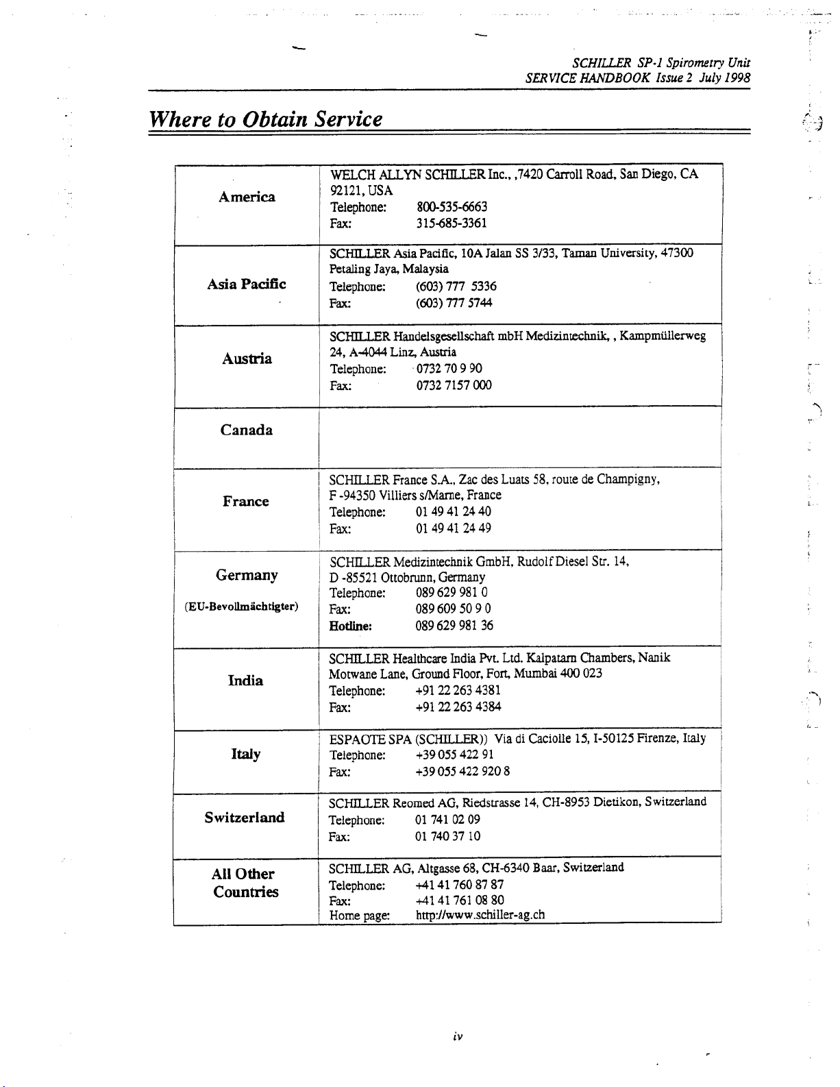
Where
Asia Pacific
to
Obtain
America
Austria
Canada
France
Service
1
WELCH
92121,
Telephone:
Fax:
SCHILLER Asia Pacific,
Petaling Jaya, Malaysia
Telephone:
Fax:
I
I
SCHlLLER Handelsgesellschaft mbH Medizintechnik, , Kampmiillerweg
24,
Telephone:
Fax:
I
I
SCHILLER France
F
Telephone:
Fax:
ALLYN
USA
800-535-6663
315-685-3361
(603) 777 5336
(603) 777
A4044
Linz,
0732 70 9 90
0732 7157
-94350
Villiers s/Marne, France
01 49 41 24 40
01
SCHILLER Inc.,
1OA
Jalan
5744
Ausma
OOO
SA.,
Zac des Luats
49 41 24 49
,7420 Carroll
SS
3/33,
58,
Road, San Diego, CA
Taman University,
route de Champigny,
47300
1
Germany
(EU-Bevollmachtigter))
India
IMY
Switzerland
All
Other
Countries
SCHILLER Medizintechnik GmbH, Rudolf Diesel
D
-85521
i
Telephone:
1
F~:
~
Hotline:
SCHILLER Healthcare India Pvt. Ltd. Kalpatarn
Motwane Lane, Ground Floor, Fon Mumbai
Telephone:
Fax:
ESPAOTE SPA (SCHILLER)) Via di Caciolle
Telephone:
Fax:
SCHILLER Reomed AG, Riedstrasse
Telephone:
Fax:
SCHILLER AG, Altgasse
Telephone:
Fax:
1
Home page:
Ottobrunn, Germany
089 629 981
089 609
089 629 981 36
+91 22 263 4381
+9122 263 4384
+39
055
+39
055
01 741 02 09
01 740 37 10
41
41 760 87 87
41
41 761 08 80
http://www.schiller-agxh
0
50
9
422 91
422 920 8
68,
CH-6340
0
14, CH-8953
Baar,
Su.
14,
Chambers,
400
023
15,1-50125
Dietikon, Switzerland
Switzerland
Nanik
Firenze, Italy
I
iv
Page 5
-
&.
-.
SCHILLER
SERVICE
SP-1
HANDBOOK
Warranty
Disclaimer
The Information
given
as
regarding the contents
changes
any person of such revision
Trademarks
SCHILLERandSP-1
of their
Copyright Notice
0
Copyright
transcribe, store in a retrieval system
electronic, mechanical, magnetic, optical, chemical,
publication without express written permission
Spiromev Unit
issue
2
July
1998
in
this
guide
has
been carefully checked for reliability; however no guarantee is
to
the correcmess
in
the
specification of the product described within at any
owners.
1998
of
the
contents and SCHILLERmakes no representations
of
this
manual. We
or
change.
areregisteredtrademarksofSCHlLLERAG.All
by
SCHILLER
AG.
reserve
All
rights reserved.
or
translate into any language, in any
of
the
right
to
You
manual
SCHILLER
AG.
or
revise
this
document and make
time
without obligation
mdemarksare the property
may
not reproduce, transmit,
fonn
or
by any means,
or
otherwise,
any
part
warranties
to
notify
of
this
Terms
of
Warranty
The SCHILLER SP- 1 is warranted against defects in material and manufacture for
one year
or
Any
unqualified persons attempt
In case
The manufacturer
apparatus
'
persons authorized by
'
instructions.
THERE
WARRANTES
MERCHANTABILITY ORFITNESS FOR APARTICULARPURPOSE
THE
(as
from date of purchase). Excluded from
as
a result of improper handling. The warranty entitles free replacement of the defective part.
liability
assembly operations, extensions, readjustments, modifications, or repairs
the
PRODUCT
for subsequent damage
to
make repairs.
of
a
defect send the apparatus to your dealer or directly
can
only be held responsible for the safety, reliability, and
if:
him,
and
unit
and approved attached equipment is
ARE
NO
EXPRESS
HEFEINABOVE
OR
OR
PARTS
THEREOF.
is
IMPLIED
SET
FORTH. SCHTLLER
this
guarantee is damage
excluded. The warranty
to
the manufacturer.
used
in
accordance with
WARRANTES WHICH
MAKES
is
void
EXTEND
NO
the
duration
caused
by
an
accident
if
unauthorized or
performance
are
carried out by
the
manufacturers
BEYOND
WARRANTY OF
WITH
RESPECTTO
of
the
THE
of
V
Page 6
-.
.
..
.
c
...
.-
SCHILLER
SERVICE
.
._
.
_.
...
.
i
.
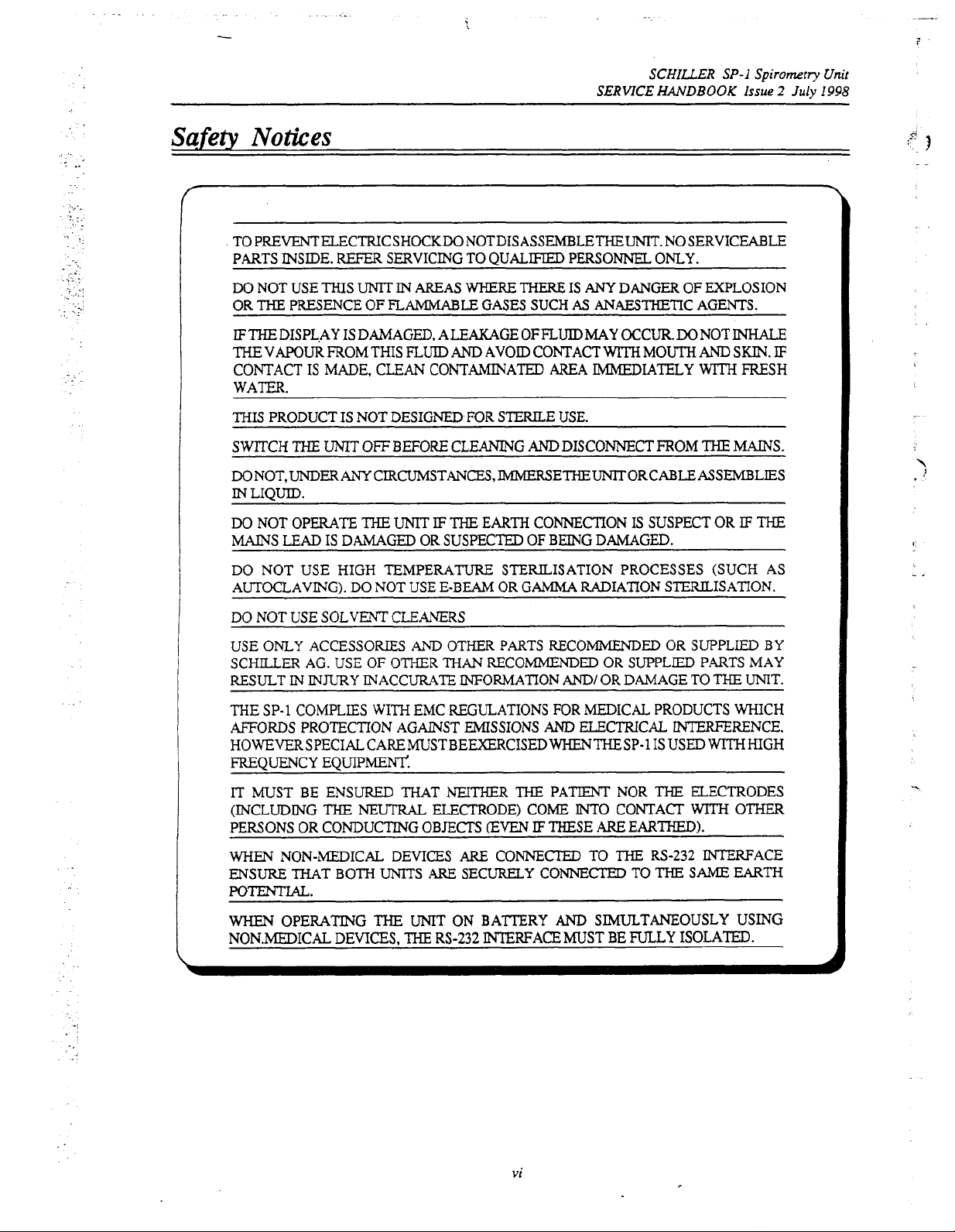
Safety
Notices
TO
PREVENTELECTRICSHOCKDONOTDISASSEMBLETHEUNIT.NOSERVICEABLE
PARTS INSIDE.
DO NOT USE
THE
OR
PRESENCE
REFER
THIS
UNIT
SERVICING TO
IN AREAS
OF
FLAMMABLE
QUALIFIED
WHERE
THERE
GASES SUCH
PERSONNEL ONLY.
IS
ANY
AS
ANAESTHETIC AGENTS.
HANDBOOK
DANGER
SP- I Spirometry
OF
EXPLOSION
Issue
2
July
Unit
I998
IFTHEDISPL.AY IS DAMAGED, ALEAKAGEOFFLUIDMAY OCCUR.DONOTINHALE
THE
VAPOUR FROM THIS
CONTACT
IS
MADE, CLEAN CONTAMINATED AREA
FLUID
AND
AVOID CONTACT
WITH
MOUTH
IMMEDIATELY
AND
WITH
SKIN.
FRESH
IF
WATER.
THIS PRODUCT IS NOT DESIGNED FOR
SWITCH
DONOT,LJNDERANY
IN
DO NOT OPERATE
MAINS
THE
UNIT
OFF
BEFORE CLEANING
CIRCUMSTANCES,JMMERSETHEUNITORCABLEASSEMBLIES
LIQUID.
THE
UNIT
IF
THE
LEAD IS DAMAGED OR SUSPECTED
STERILE
USE.
AND
DISCONNECT FROM
THE
EARTH CONNECTION IS SUSPECT OR
OF
BEING DAMAGED.
MAINS.
IF
THE
I
DO
NOT USE HIGH TEMPERAW STERILISATION PROCESSES (SUCH AS
AUTOCLAVING). DO NOT USE E-BEAM OR GAMMA RADIATION STERDLISATION.
DO
NOT
USE
SOLVENT
USE ONLY ACCESSORIES
SCHILLER AG. USE
RESULT
THE
AFFORDS
IN
INJURY INACCURATE INFORMATION
SP-1 COMPLIES WITH EMC REGULATIONS FOR MEDICAL PRODUCTS WHICH
PROTECTION AGAINST EMISSIONS
HOWEVERSPECIALCAREMUSTBEEXERCISEDWHENTHESP-1
CLEANERS
AND
OF
OTHER
OTHER PARTS RECOMMENDED OR SUPPLIED BY
THAN
RECOMMENDED
AM)
OR SUPPLIED PARTS MAY
AND/
OR DAMAGE TO
THE
UNIT.
ELECTRICAL INTERFERENCE.
ISUSED WITHHIGH
FREQUENCY EQUIPMEN?:
IT
MUST BE ENSURED THAT NEITHER THE PATIENT NOR
(INCLUDING
PERSONS OR CONDUCTING OBJECTS
WHEN
ENSURE
THE
NEUI'RAL
NON-LMEDICAL DEVICES
ELECTRODE) COME
EVEN
IF
THESE
ARE
CONNECI'ED TO
INTO
THAT BOTH UNITS ARE SECURELY CONNECTED TO
ARE
THE
ELECTRODES
CONTACT
WITH
EARTHED).
THE
Rs-232 INTERFACE
THE
SAME
OTHER
EARTH
POTENTIAL.
WHEN
NONMDICAL DEVICES,
OPERATING
THE
UNIT ON BA?TERY
THE
RS-232
AND
INTERFACE
MUST BE FULLY ISOLATED.
SIMULTANEOUSLY USING
vi
Page 7
SCHILLER
SERVICE
HANDBOOK
SP-1
Spirometry
c
Unit
Issue
2
July
1998
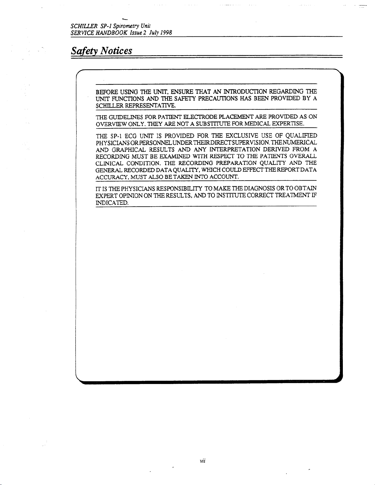
Safety
BEFORE USING
UNIT
SCHLLER REPRESENTATIVE.
THE GUIDELINES FOR PATIENT ELECI'RODE PLACEMENT
OVERVIEW
~
THE
PHYSICIANS ORPERSONNEL UNDERTHEIRDIRECTSUPERVISION. THENUMERICAL
AND
RECORDING
CLINICAL CONDITION.
GENERAL RECORDED DATA QUALITY, WHICH COULD EFFECT
ACCURACY, MUST
IT IS THE PHYSICIANS RESPONSIBILITY
EXPERT OPINION ON
INDICATED.
Notices
THE
UNIT,
ENSURE
FUNCTIONS
SP-1 ECG UNIT IS PROVIDED FOR
GRAPHICAL RESULTS
ONLY.
MUST
AND
THEY
BE
ALSO
THE
THE
SAFETY
ARE
NOT A
AND
EXAMINED
THE
RECORDING PREPARATION QUALITY AND
BE TAKEN
RESULTS,
THAT
AN
INTRODUCTION REGARDING THE
PRECAUTIONS
SUBSTl"E
THE
ANY
INTERPRETATION DERIVED
WITH
RESPECT
INTO
ACCOUNT.
TO
MAKE
AND
TO
INSTITUTE
HAS
FOR MEDICAL EXPERTISE.
EXCLUSIVE USE
TO
THE
THE
DIAGNOSIS OR TO OBTAIN
CORRECT TREATMENT
BEEN PROVIDED BY A
ARE
PROVIDED AS
OF
QUALIFIED
PATlENTS
OVERALL
FROM
ON
A
THE
THE
REPORT DATA
IF
vii
Page 8
-
SCHILLER SP-1
SERVICE
HANDBOOK
Spirometr?,
Issue
2
July
Unit
1998
~
._..
_-
What’s
in
THE
SERVICE
MODULE
TION
NECESSARY
AND
REPLACE A FAULTY
EDGEOFTHESP-1
WITH
STANDARD
The
book
Chapter
The purpose
to give a basic introduction
operation and function of each key briefly explained. The information in
background to
SCHILLER
Chapter
This chapter provides a functional overview
by functional block diagrams.
Chapter
2
3
this
Book
PHILOSOPHY
LEVEL.
is
1
-
Operating Elements
SP-1
-
Functional Overview
-
Fault Diagnosis
THE
TO
BUTDOESREQUIRETHATTHESERVICE~G~RISFAMlLIAR
WORKSHOP PRACTICES.
divided
into the following
of
this chapter is
the
operating functions
Operating Manual.
PURPOSE OFTHIS
ENABLE
to
to
the
FOR
ALL
THE
MODULE.
chapters:
provide
an
SP-1.
This chapter gives details of the operator controls with the
only.
SCHILLER
BOOK
SERVICE
THIS
BOOK
easy reference for all the
Complete opting information is provided in the
of
the
SP-1
UMTS
IS
TO
ENGINEER
ASSUMES
The functional description
IS FAULT
PROVIDE
TO
EFFlCIENTLY LOCATE
NO
main
ALL
DETAILED
operator functions and
this
FINDING
THE
INFORMA-
KNOWL-
chapter provides
is
supported
TO
a
!-
-\
7’
3
1
This chapter provides a guide
logical sequence of
the text where needed.
Chapter
and after replacement. Functional checks that must be
also
Chapter
test procedures
Chapter
This Chapter provides the part numbers and reordering information for
Also
adjustment or fault finding procedures.
Chapter
4
-
This
chapter gives
attributes of the unit briefly described. The physical description
showing the internal location of all modules. Removal and Replacement instructions for
replaceable modules are also provided in
of
tools,
jumper settings, adjustments,
provided.
5
-
Adjustments
This chapter provides
6
-
Spare Parts
included
7
-
Technical
fault
Module Removal
an
all
that
can
in
this chapter
to
locate a fault
finding algorithms and procedures. Illustrations are provided to support
and
overview of the physical construction of the
and
adjustments and settings.
be
performed to check the functioning
are
details of my
to
module level. The diagnostics are presented in a
Replacement
SP-1
with the main physical
is
supported by illustrations
this
chapter. Each procedure
settings or
special
carried
Also
detailed in
special
test
requirements
out after replacing a new module are
equipment or
is
autonomous with details
that
are
this
chapter are basic functional
of
the unit.
all
replaceable modules.
special
tools
required before
Data
all
required for
The full technical specification of the
Chapter
This Chapter explains
diagrams.
8
-
Glossary
all
the acronyms and signal titles used in
SP-1
is
given in
...
Vlll
this
chapter.
this
book and in the
SP-1
circuit
Page 9

,
..
SCHILUR
SERVICE
.-.
.
What’s in this
SP-I
HANDBOOK
Index
Spiromrry
Issue
Book
Unit
2
July
I998
Circuit
The
circuit
for
information
Diagrams & Board
diagrams
and component
only.
The philosophy
ment.
Our
aim
information and the latest technological developments. We
reserve the right
improvements at any time.
Your
suggestions and comments are welcome. Please contact
the
SCHILLER
Fax
41
41
Layouts
layouts
are
provided
We
Need
Your
of
SCHILLER
is
to provide the
to
revise
this
document and make changes
Technical Documentation Department:
761
03
34
for
all
boards.
Help
is
one
of
continuous improve-
user
with the most up-to-date
These details are provided
or
Page 10

.
. . .
.
-
__
.
.
__
.
.
.
-
.
.
.
-
List
qf
Symbols
6
A
Mains
Supply
Battery Operation
FllSe
LCD Contrast
Potential
Attention - General Warning
Equalisation
(common
SCHILLER
SERWCE
Ground)
Sign
-
see accompanying documentation
HANDBOOK
SP-I
Spirometry
Issue
2
July
Unit
I998
Type
BF
equipment - safe for external applications
Manufacturers Take-back
0
-
Mains Power
I
-
Mains Power
ONlOFF
Off
-
mains supply disconnected from unit
On
-
mains
guarantee
supply
for used batteries
connected
to
unit
X
Page 11
SCHILLER
SERVICE
HANDBOOK
SP-1
Spirometry
Issue
Unit
2
July
1998
Chapter
Operating Elements
I
Procedure Overview
Introduction
Location
Keyboard
Main
Menu Overview
Setting Screen Contrast
System
Pulmonary
Obtaining
Flow Sensors
Setup Menu
Sending
Function Test Procedure
a
Printout
and
Contents
Entering
Operating
Data
Chapter
Elem
1.2
1.3
1.4
1.5
1.6
1.7
1.8
1.10
1.13
1.15
1.16
en
1
ts
Page
1.1
Page 12
Chapter
Operaring Elements
I
SCHILLER
SERVICE
HANDBOOK
SP-I
Spirometry Unit
Issue
2
July
I998
Procedure
.
.
.,
--
/
General
Settings
1
Date
Time
1
Device
Norm values
1
Contrast
1
Print
User
1
Memory
etc.
L--
Overview
for
every
Insert new filterkcreen
Insert new sensor
-7
I
I
I
I
I
I
Enter Patient Data
newpafient
(SP-20)
I
Repeat tests
or
I
(3
more times)
1
Make Measurements
P
1
I
Post-medication
tests
1
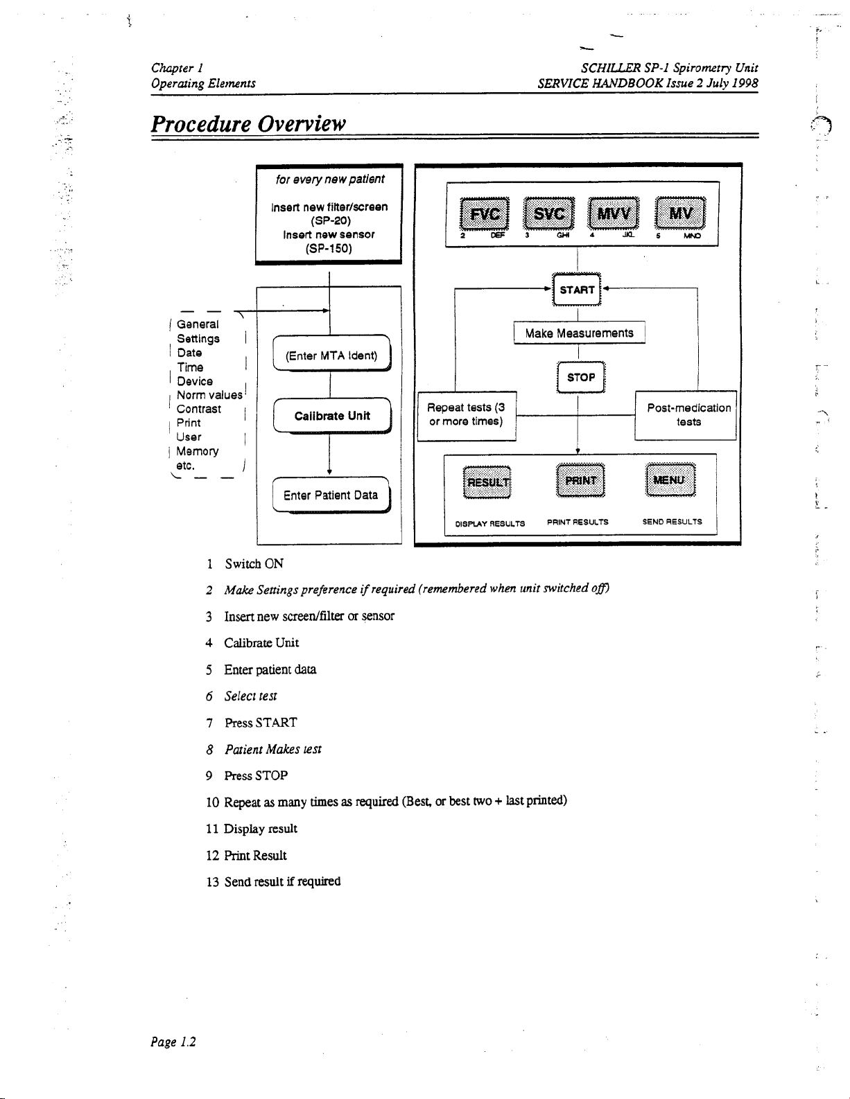
Switch
ON
2
Make
Settings preference
3
Insert new screen/filter
4
Calibrateunit
5
Enter patient
6
Select test
7
PressSTART
8
Patient Makes test
9
RessSTOP
10
Repeat
11
Display
12
PrintResult
13
Send
result
as
many
result
data
if
required
times
if
required (remembered
or
sensor
as
required
(Best,
or
best
two
when
+
unit switched
last printed)
ofl
Page
1.2
Page 13
SCHILLER
SERVICE
HANDBOOK
SP-I
Spirometry
Issue
Unit
2
July
1998
Chapter
Operming
I
Elements
-
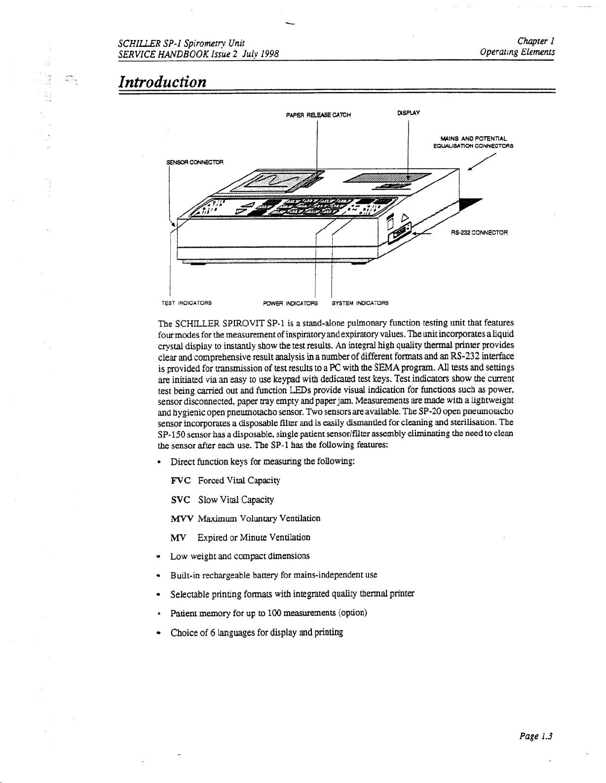
Introduction
TEST INDICATORS POWER
The SCHILLER SPIROVIT
SP-1
PAPER REEASE
INMCATORS
is
a stand-alone pulmonary function
CATCH
SYSTEM
INDICATORS
MSPUY
WINS
AN0
RS-232
tb
POTENTIAL
CONNECTOR
features
EauALlSAnONCONNECTORS
sting unit
four modes for the measurement of inspiratory andexpiratory values. The unit incorporates aliquid
crystal display
clear and comprehensive result analysis
is provided for msmission of
are
initiated
test being carried out and function
sensor disconnected, paper
and hygienic open pneumotacho sensor. Two sensors are available. The
to
instantly show the test results.
test
results to
via
an
easy to use keypad with dedicated test keys. Test indicators show the current
LEDs
tray
empty and paperjam. Measurements are
An
integral high quality thermal printer provides
in
anumber of different formats and
a
PC
with the
provide visual indication
SEMA
program.
for
an
RS-232
All
tests
functions such
made
with a lightweight
SP-20
open pneumotacho
interface
and settings
as
power,
sensor incorporates a disposable filter and is easily dismantled for cleaning and sterilisation. The
SP-150 sensor
the sensor after each use. The SP-1
has
a disposable, single patient sensor/fdter assembly eliminating the need to clean
has
the following features:
Direct function keys for measuring the following:
FVC
Forced Vital Capacity
SVC
Slow
Vital
Capacity
MVV
Maximum Voluntary Ventilation
MV
Expired or Minute Ventilation
Low weight and compact dimensions
Built-in rechargeable battery for mains-independent use
Selectable printing formats with integrated quality thermal printer
9
Patient memory for up
Choice
of
6
languages for display and printing
to
100
measurements (option)
Page
1.3
Page 14
ic
Chapter
I
Operating Elements
Location
As
with
all
The
unit
The
unit
The
unit
transformers
unit
and
Potential Equalisation
In certain
equipment. Connect the earth potential'equalisation
hospital common
frame. Note
same common ground. The part number of
Power Supply
SERVICE
medical
should
units,
the following general
not
be
stored
or
rules
are
to
be
not&
operated in a wet, humid or dusty environment.
may not come into contact with acidic steams or liquids.
should not
the
circumstances
be
set up near radiology or diathermic systems, or near Iarge
or
electrical motors.
mains
supply
intederence
Ensure
is
maintained
can
that
a
minimum
be
caused by externai electrical equipment or
distance of 1 meter between the
connection
ground
or,
if
a
that
all
other electrical equipment
common
ground is
not
present,
in
close
proximity
the
potential equalisation cable is
to
should
SCHILLER
HANDBOOK
at the back
of
the
SP-1
SP-1
Issue
to
a metal framework e.g. the
also
be
connected to the
2.310
005.
Spirometry
2
July
radio
the
bed
Unit
1998
The unit can
connection
connected to the
battery capacity
the
mains
15
hours
A
fully
remain connected to the
Switching
The
SPIROVlT
be
operated from the
is
on the
mains
is
supply
by
to
be
fully
rear
of the unit. The
supply. A battery indicator lamp confirms
limited, the indicator flashes.
means of the supplied power cable. A totally discharged battery needs less than
recharged
(60%
mains
in less
or
from
mains
than
To
charged battery lasts approximately 7 hours of normal use
mains
supply without any danger of damage toeither the battery or the
On
and
Off
SP-1
is
switched on and off with the
the built-in rechargeable battery. The mains
indicator lamp
is
always lit when the unit
battery
operation. When the
recharge the battery, connect the apparatus
3
hours,
90%
in 6 hours).
(SP-1R
6
hours). The unit can
ON
and
OFF
keys.
is
to
unit.
Page
1.4
Page 15
..
.
:-
..
..
SCHILLEU
SERVICE
SP-I
HANDBOOK
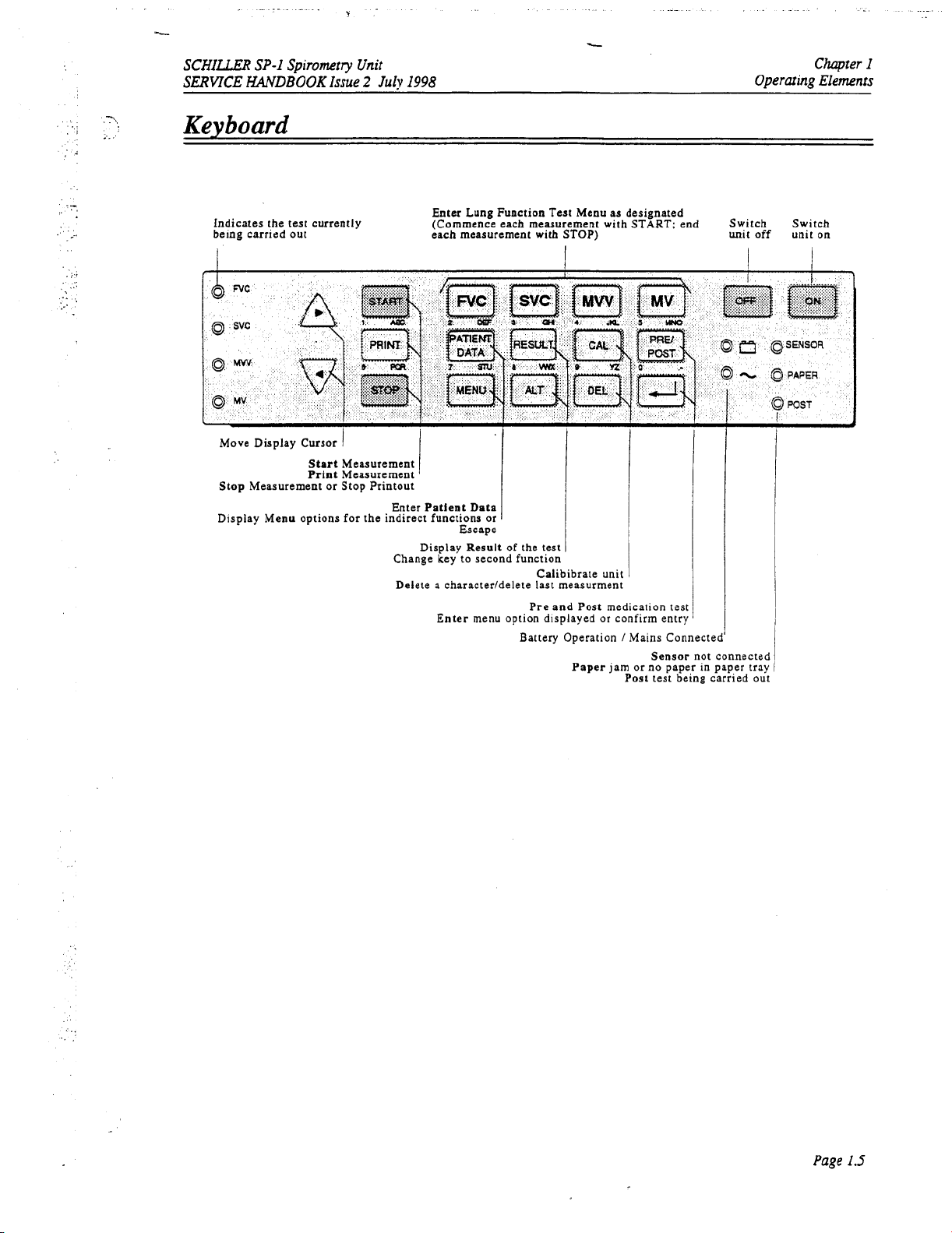
Keyboard
Indicates the
being carried
Spirometv
test
out
Unit
Issue
2
July
1998
currently (Commence each measurement with
Enter Lung Function Test Menu as designated
each measurement with STOP) unit
L
START;
Chapter
Operaring Elements
end Switch Switch
off
unit on
I
Move Display
Stop Measurement
Display Menu options
Cursor
Start
Print Measurement
or
1
Measurement
Stop Printout
for
Enter Patlent Data
the indirect functions
Display Result
Change key to second function
Delete a character/delete last measurment
or
Escape
of
the test
1
Calibibrate unit
Enter menu option displayed
Pre and Post medication test
Battery Operation
Paper jam
or
confirm entry
/
Mains Connected'
Sensor not connected
or
no paper in paper tray
Post test being carried out
Page
IS
Page 16
Chapter
Operating
I
Elements
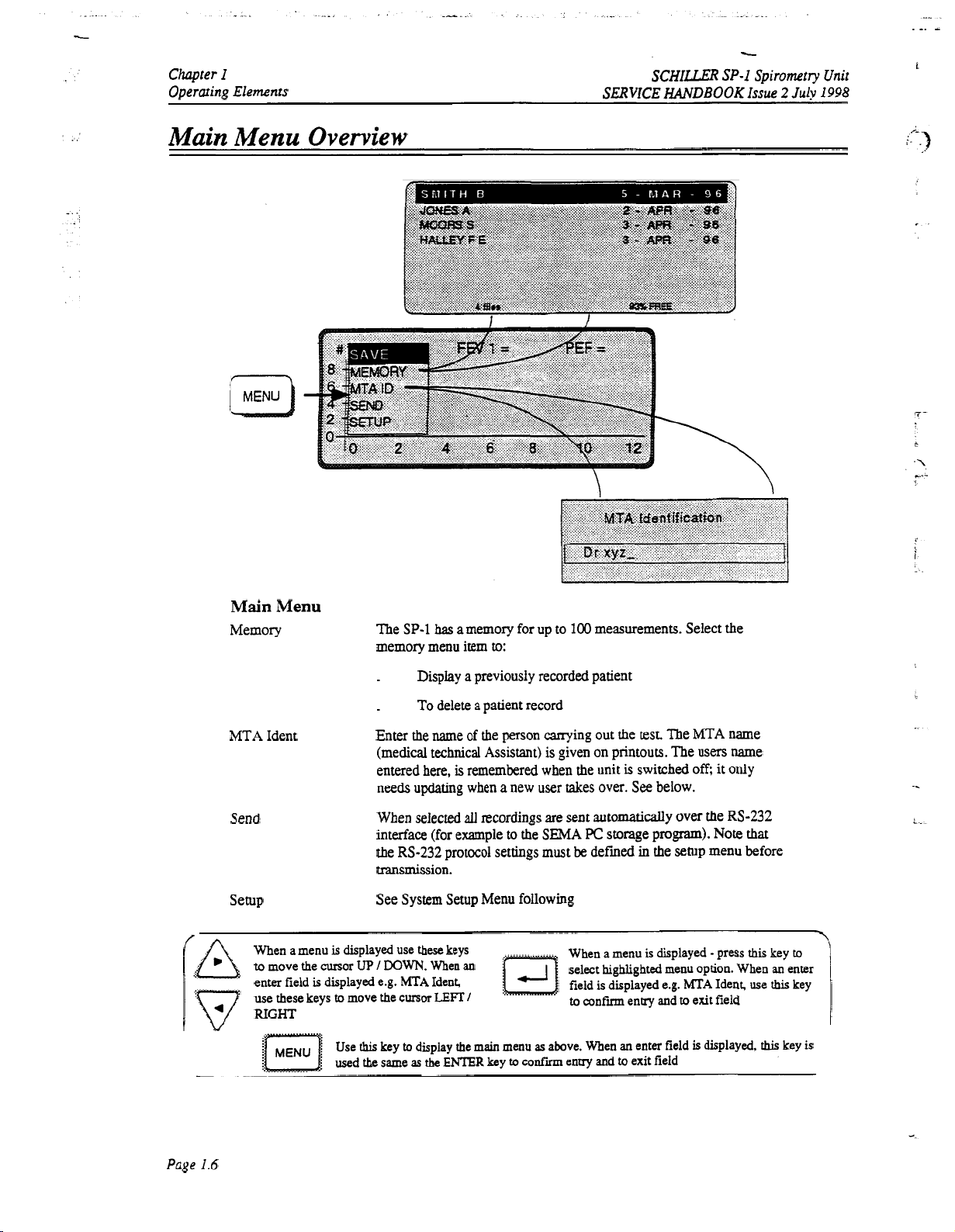
Main Menu Overview
SCHILLER
SERVICE
SP-I
HANDBOOK
Issue
Spirometry Unit
2
July
1998
1
Main
Menu
Memory
MTA Ident
Send
Setup
When a menu
to
move the cursor
enter field
use these keys
RIGHT
:/
. . . .
is
.
....
..c
is
displayed use these keys
UP
displayed e.g.
to
move the
Use
this
used the same
The
SP-1
has
a memory for up to
memory menu item
Display a previously recorded patient
.
To
.
Enter the name
(medical technical Assistant) is given on printouts. The users name
entered here,
needs updating when a new user takes over. See below.
When selected
interface (for example
the
delete a patient record
RS-232
protocol settings must
to:
of
the person carrying out the
is
remembered when the unit
all
recordings are
to
the
100
sent
SEMA
be
measurements. Select the
test.
The
MTA
is
switched
automatically
PC
storage program).
defined
in
the
off;
over the
Note
setup
menu before
it
name
only
RS-232
that
transmission.
See System Setup Menu following
I
WWN.
When
h4TA
Ident
cursor
LEn
key
to
display the main menu
as
the
ENTER
an
I
key
to
confii
When a menu
select highlighted menu option. When
is displayed e.g.
field
to
confm
as
above. When
entry and
is
displayed - press this key
entry and
an
enter field
to
exit field
h4TA
to
exit field
is
Ideat, use
displayed,
an
this
this
-.
to
enter
key
I
key
is
Page
1.6
Page 17
_-
-
..-
SCHILLER
SERVICE
SP-I
Spirometry Unit
HANDBOOK
Issue
2
July
I998
Setting Screen Contrast
Setting
Change the contrast
Press the
and
Entering
Printed below certain keys on the keyboard
key once to enter the first
the third character.
The character is displayed on the screen
and move
Use
Press the
When an enuy field requires anumericai input e.g. date of
selected. When an entry field requires a letter input e.g. patient name, the letter keys are
automatically selected.
conversely a letter input required
number key enables
the
Contrast
of
the screen
ALT
key and the
MENU
DOWN
data
in
a field
character,
to
the
next character position.
the left and right cursor keys at any the to select a position
ENTER
key or the MENU key to
If
a numerical input is required for example in the patient name, or
in
this.
Therefore when entering
Operaring Elements
and
to
Entering
your preference
key together then change the contrast with the cursor keys
are
letters.
twice
to enter the second character, and three times to enter
as
entered.
the date
Press
confum
of
birth,
dam
Data
as
follows:
In
a
data
field (e.g.
the right cursor key to confm the entry
to
entry and exit the field.
birth,
the number keys are automatically
pressing the
ALT
MTA
Ident) press the
change that character.
key before the character/
UP
Chapter
I
ALT
+
key = number input in character field
ALT
+
key = character input in number field
Page
1.7
Page 18
L
Chapter
Operating Elements
I
SCHULER
SERVICE
SP-I
HANDBOOK
Spirometry
Issue
2
July
Unit
I998
System
Press this
option
key
Setup
to
Menu
key
or
to
change setting.
program
to
select highlighted menu
Press
the
settings and
exit
menu
i
.=-
\\
MENU
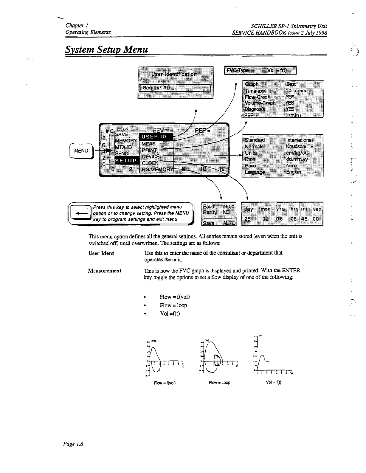
This menu option defmes
switched off) until overwritten. The settings are
User Ident
Measurement
all
the general
Use
this
operates
This
is how the
key toggle the options
Row
Row=lOop
Vol
settings.
to
enter the name of the consultant
the
unit
FVC
gmph is displayed and printed. With the
=
f(v0l)
=f(t)
All
enaies remain stored (even when the unit is
as
follows:
or
department
to
set a flow display of one of the following:
that
ENTER
Page
1.8
Page 19
SCHILLXR
SERVICE
SP-I
Spirometry Unit
HANDBOOK Issue 2 July
I998
System Setup Menu (cont.)
This
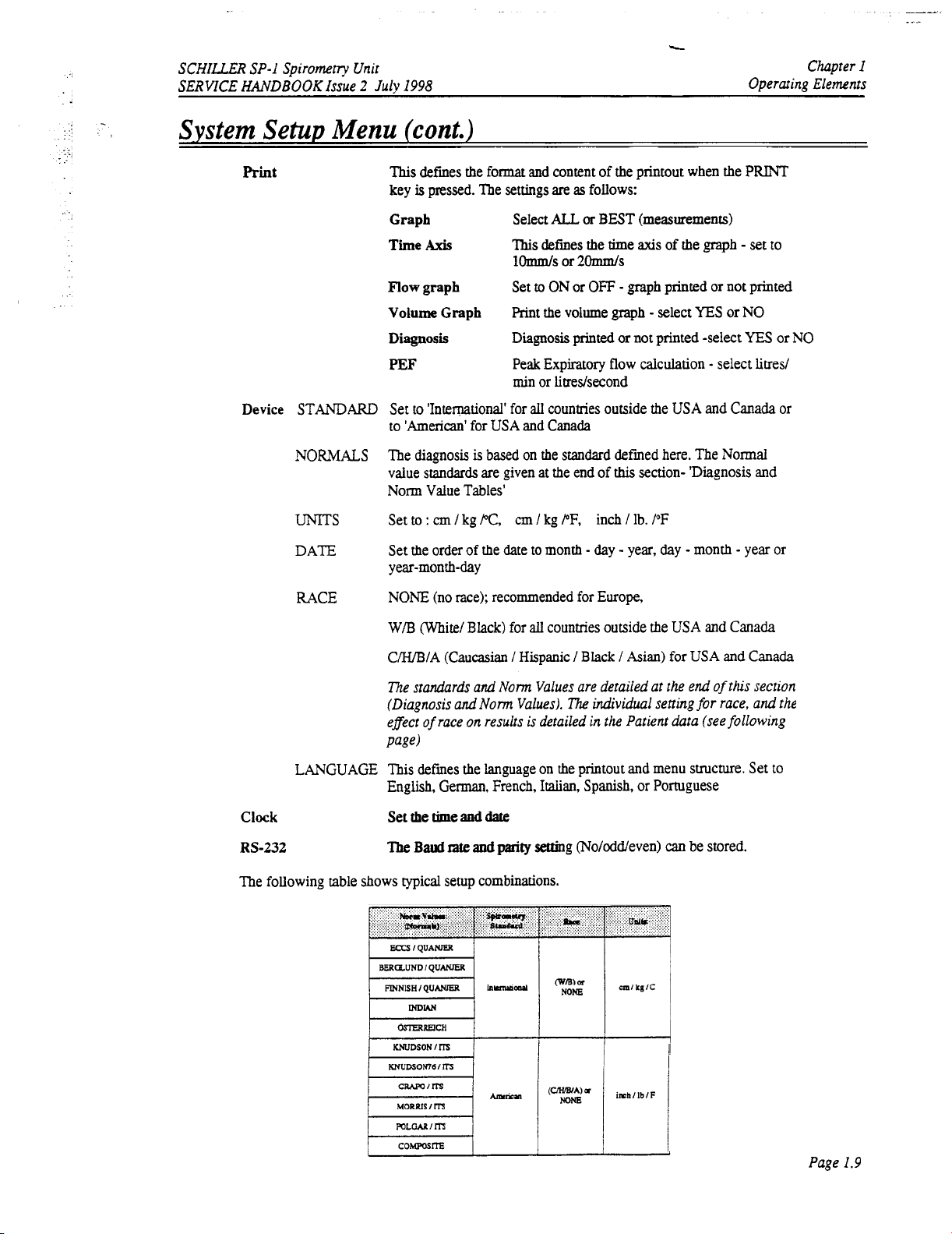
Print
defines the format and content of the printout when the
key
is
pressed. The settings
are
as
follows:
\
Chapter
Operating Elements
I
PRINT
Device
STANDARD
NORMALS
UNITS
DATE
RACE
Graph
Time
Axis
Flow
graph
Volume
Diagnosis
Graph
PEF
Select
ALL
or
BEST
(measurements)
This
defines
the
time
axis
1-s
Set
to
ON
or
or
2Ws
OFF
-
gaph printed or not printed
Print the volume graph - select
Diagnosis
printed
or
not printed -select
Peak Expiratory flow calculation - select litred
min or litredsecond
Set
to
'International' for
all
countries outside the USA and Canada or
to 'American' for USA and Canada
The
diagnosis
value standards are given at the end
is
based on the standard defrned here. The Normal
of
this
section- 'Diagnosis
Norm Value Tables'
cm
/
kg
PF,
Set
to
:
cm
/
kg PC,
Set the order of the date to month
y
ear-month-day
inch / Ib. /OF
-
day - year,
NONE (no race); recommended for Europe,
W/B
(White/ Black) for
C/H/B/A (Caucasian
all
countries outside the
/
Hispanic / Black / Asian) for USA and Canada
of
the
graph
YES
day
-
month - year or
USA
and Canada
or
-
set
NO
YES
to
or NO
and
The standards and
(Diagnosis and
of
effect
page)
race
Norm
Values are detailed at the end
Norm
Values).
on
results is detailed in the Patient data (see following
LANGUAGE This defines the language on the printout and menu smcture. Set to
Clock
RS-232
English, German, French,
Set the time and date
The
Baud rate and parity setting (Noloddeven) can be stored.
Italian,
The following table shows typical setup combinations.
The
dividual
setting
Spanish, or Portuguese
iohl
IblF
of
for
race,
this section
and
the
Page
I.9
Page 20
Chapter
Operating
I
Elements
SCHILLER
SERVICE
SP-I
HANDBOOK
Spirometry Unit
Issue
2
July
I998
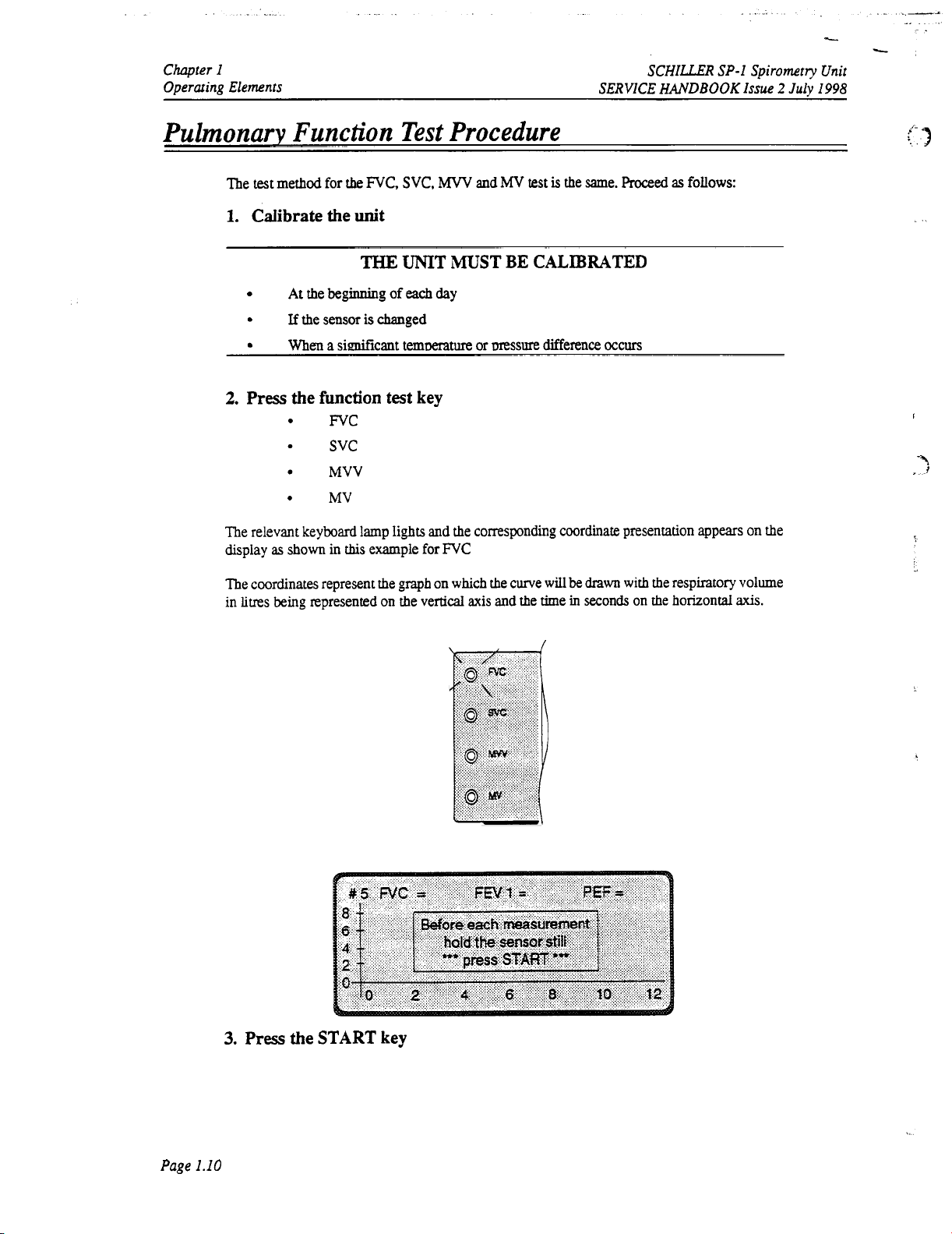
Pulmonary
The
1.
2.
The relevant keyboard lamp
display
The coordinates represent the
in
litres
Function
test
method for
Calibrate
At
If
When
Press the
as
shown
being represented on the vertical
the
FVC, SVC,
the
unit
THE
the beginning
the sensor
is
a
siNicant
function
FVC
SVC
MVV
MV
in
this
example for
Test Procedure
MVV
and
MV
UNIT
of
changed
ternmature or
test key
lights
graph
MUST
each
day
and the corresponding coordinate presentation appears on the
FVC
on
which
BE
mssure
the curve
axis
and the time in seconds
test
is
the same.
Proceed
CALIBRATED
difference
will
be
drawn
occurs
with
on
as
follows:
the respiratory volume
the horizontal
axis.
:-
I
.”;
3
Page
1.10
3.
Press
the START key
Page 21
c
SCHILLER SP-I Spirometry
SERVICE
Pulmonary
HANDBOOK
Issue
Function
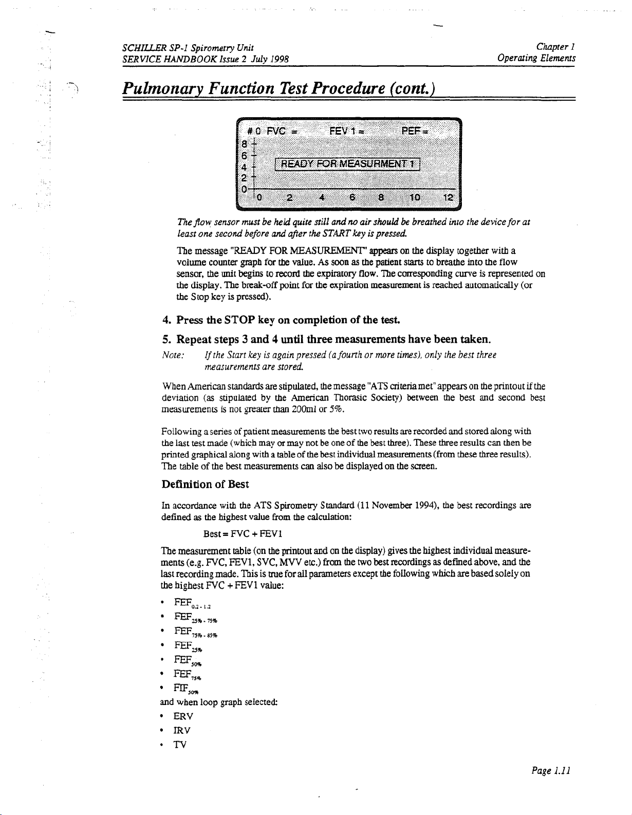
The
flow
sensor must be
least one second before
The message
volume counter graph for
sensor,
the display. The break-off point for the expiration measurement
the Stop key
4.
Press the
5.
Repeat steps 3 and 4 until three measurements have
Note:
"READY
the
unit
is
STOP
Ifthe Start
measurements are stored.
Unit
2
July
1998
Test
held
quite
and
after the
FOR
MEASUREMENT'
the
value.
begins to
pressed).
record
the expiratory
key on completion
key
is again pressed (a founh
Procedure
still
and
no
air
should
START
key
is
pressed
appears
As
soon
as
the
patient
flow.
The corresponding curve
of
the
test.
or
more times), only the best three
(cont.)
be
breathed into the device
on
the display together with a
starts
to
breathe into the flow
is
reached automatically (or
been
taken.
Chapter
Operating Elements
for
at
is
represented on
I
When American
deviation
measurements
Following a series
the
last
test
printed graphical dong with
The table of the best measurements can
Definition
In accordance with the
defined
The measurement table (on the printout and on the display) gives the highest individual measurements (e.g.
last recording made. This is true for all parameters except the folIowing which are
the highest
'
as
FEFo.2.
EEF,%.75%
FEF,,%.,S%
standards
(as
stipulated by the
is
not greater than
of
made (which may
of
Best
the highest value from the calculation:
Best
=
FVC + FEVl
FVC,
FEV1,
FVC
+
1.2
are stipulated,
patient measurements the best two results are recorded and stored along
or
may
a
table of
ATS
Spirometry Standard
SVC,
MVV
FEVl
value:
the
message
American
2OOml
Thorasic Society) between
or
5%.
not
be
one of the
the
best individual measurements (from
also
be displayed on
etc.) from
the
"ATS
criteriamet" appears on the printout
the
best and second best
best
three). These three results can then be
these
the
screen.
(11
November
two
best recordings
19941,
the
best recordings
as
defined above, and the
three
based
if
with
results).
are
soleIy on
FEFZ5
'
FEF,,
FEF,,%
%?%
and
when loop graph selected:
ERV
IRV
*Tv
the
Page
I.11
Page 22
Chapter
I
Operating Elements
_-.
.
-..
L
c
SCHILLER
SERVICE
HANDBOOK
SP-I
Spirometry
Issue
2
July
Unit
1998
i'
F
,
_.
I-
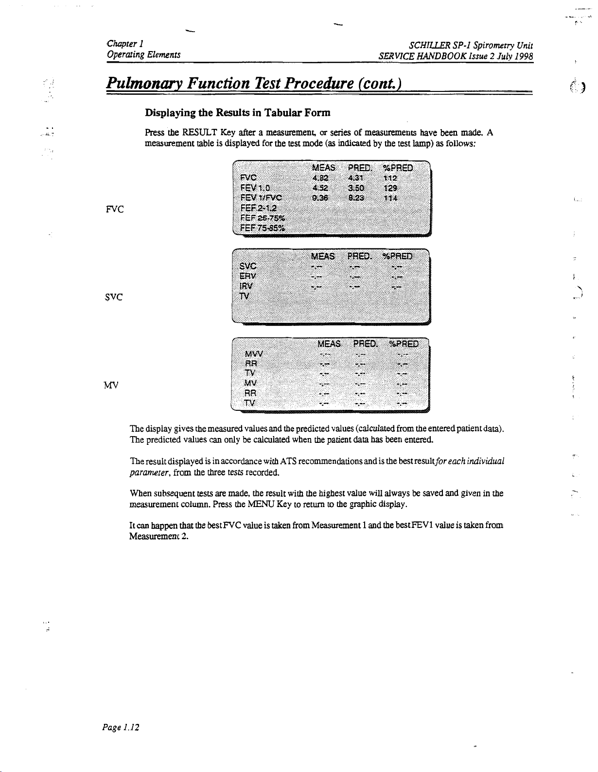
Pulmonary Function
Displaying
Press
.
the
measurement table is displayed for the
the
Results
RESULT
Key
Test
in Tabular
after
a
measurement,
Procedure (cont.)
Form
or
series
of
measurements have been
test
mode
(as
indicated by the test lamp)
as
follows:
made.
A
FVC
svc
..
;
MV
The display gives the measured values and the predicted values (calculated from the entered patient
The predicted values
The result displayed is in accordance with
parameter,
from the
When subsequent
measurement column.
It
can
happen that
Measurement
three
tests
the
bestlVC value
2.
can
only
tests recorded.
are
made,
Press
the
be
calculated when the patient
ATS
recommendations and is the best resultfor
the
result with the highest
MENU
Key to return
is
taken from Measurement 1 and the best FEVl value is taken from
data
has
been entered.
value
will
always
to
the graphic display.
be
saved and given in the
data).
each individual
Page
1.12
Page 23
SCHILLER
SERVICE
SP-I
Spiromtry
HANDBOOKIssue
Unit
2
July
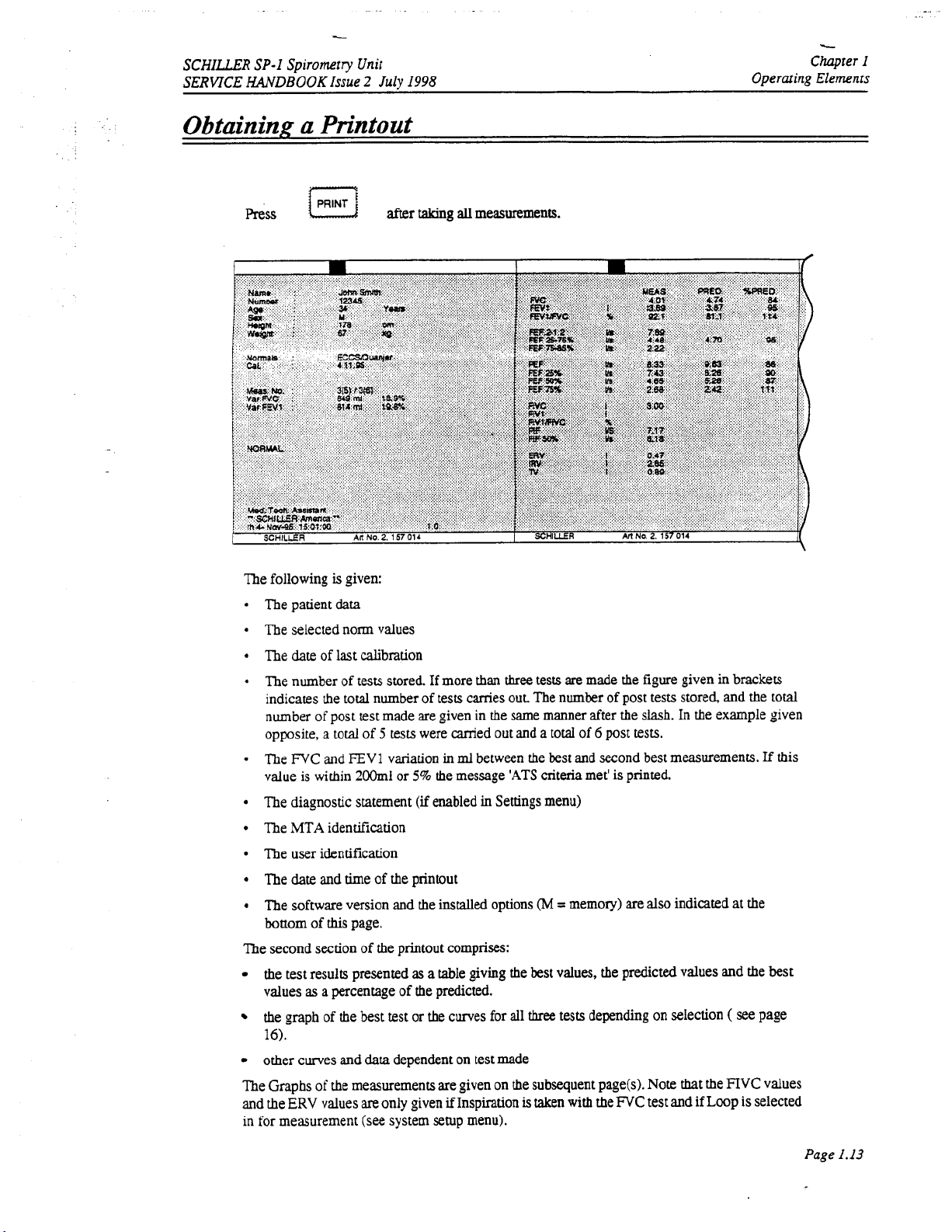
Obtaining a Printout
1998
Chapter
Operaring
I
Elements
Press
The following
The patient
is
data
given:
after
taking
all
measurements.
The selected norm values
The
date
of
last calibration
The number of tests stored. If more than
three
tests
are
made the figure given in brackets
indicates the total number of tests wries out The number of post tests stored, and the total
number of post test made are given in
opposite, a
The
value
The diagnostic statement
The
FVC
and
is
within
MTA
identification
total
of
5
tests were canied out and a total of 6 post tests.
FEVl variation
2oOml
or
in
5%
the message
(if
enabled
the
same manner after the slash. In
ml
between the best and second best measurements.
'ATS
criteria
met'
is
printed.
in
Settings menu)
the
example given
The user identification
The date and
The software version and the
bottom
The second section
the test results presented
values
the graph of the best test or the curves for
16).
other curves and
time
of
the printout
installed
of
this
page.
of
the printout comprises:
as
a
table
as
a
percentage of the predicted.
data
dependent on test made
options
giving the
all
(M
=
memory) are also indicated
best
values, the predicted values and
three
tests depending on selection
at
(
see
the
the
If
this
best
page
The Graphs of the measurements are given on the subsequent page(s). Note
and the
ERV
values
are
only given
if
Inspiration
is
taken with the
FVC
test and if Loop is selected
in for measurement (see system setup menu).
that
the
FIVC
values
Page
1.13
Page 24

c
Chapter
I
Operating Elements
Pulmonary
_.
..
..
-.
-.
..~
SERVICE
Function Test Procedure (cont.)
. . . . .
SCHILLER
HANDBOOK
SP-1
.
..
. . .
Spirometry Unit
Issue
2
July
1998
._.
-.
T.
L
crl
::.
.
j
Forced
For
Note:
To
Vital
this
Capacity (FVC)
test
the
patient must exhale
Test
as
quickly
as
possible
The FVC test employs the "Back extrapolation" method.
(>0.15
lim
or
5%
of
FVO,
is too large
carry
out
the
test
for Forced
Vital
Capacity
then a waming appears
0,
from
press
key
the time of
If
"FVC"
coordinate presentation appears on the display
The patient must exhale
understands what
be
immediately followed by a
is
required
as
quickly
as
of
him.
If inspimtory
maximum
possible &om the time
measurements
of
starring
are
required, the exhaiation can
inhalation. The inspimion results will
printout.
Before initiating a printout
previously. Press the
Slow
Vital
PRINT
Capacity (SVC)
key to
obtain
Test
ensure that the
if
printout
as
seuings
defined.
of
the
FVC
Test,
The patient should breathe normally 3 times and then inhale maximally
then exhale maximally. Make
MVV
Test
The patient should breathe
make
sure
that he understands what is required of him.
sure
as
deeply and
that
the patient understands
as
rapidly
as
what
possible over a
period
starring
the test.
the extrapolated volume
on
the display
and the corresponding
the test
so
be
sure
that
be
given on the
are
correct
as
detailed
to
total lung capacity and
is
required
of 6 to
of
him.
12
seconds
he
so
,
WARNING
EXTREMECARESHOULDBEEXERCISEDWHENPERFORMINGTHIS~TAS
IS
A
DANGER
OF
HYPERVENTILATION.
ENSURE
THAT
THE
PATIENT
DOWN.
MV
Test
The patient should breathe
that
Make sure
the patient understands what is required
as
normally
as
possible for up
to
of
60
seconds,
him.
but
for at
least
THERE
IS
SITTING
20
seconds.
Page
1.14
Page 25

SCHILLER
SERVICE
HANDBOOK
SP-I
Spiromrry
Issue 2 July
Unit-
I998
Chapter
Operating Elements
I
Pulmonary Function
...
.
:.
7
Post-Medication
In
order
to
cany
Lamp
lights
The post-medication
measurements stored). The printout following post-medication
pre and post-medication
shown
as
the best results (pre/post), results
and the percentage change (i.e. difference) between pre and post-medication results.
Tests
out
post-medication
tests
tests
Test
are carried
Procedure
tests
for
comparison,
out
in
the
(the premedication curve is bold). The measurement results are
as
a percentage
(cont.)
press
same way
of
the
PEWPOST
as
the premedication tests (three
tests
will give the curves
those predicted,
key and
(both
pre and post)
"POST"
of
both
The
diagnosis resulting
from
the premedicarion
Sending
Measurements can be sent
cation parameters,
side. See Chapter
Connect the
Carry out the measurement(s)
Press the
When the transmission is complete a message
has
been completed.
PC
and on the unit. Check the cable connection. Ensure
are
the
same
3
PC
MENU
in
both the
to
the
ie
baud
rate, parity etc. are
(RS-232
Check) forfurtherdetails.
to
the
RS-232
key and select
If
an error message
PC
and the
SEMA
connector on the right hand side
as
descriid previously.
SEND
is
unit
fest
is
also
given
on
data
management system. Make sure
set
the Same on the transmitting
To
send ameasurement proceed
is
displayed showing
displayed e.g.
(SETUP
'serial
that
menu).
link
time-out' check settings in the
the
Baud rate and the parity settings
this
printout.
that
the communi-
and
the receiving
as
of
the
unit.
that
successful transmission
follows:
Page
1.15
Page 26
Chuprer
I
Operating
Elements
SCHILLER
SERVICE
HANDBOOKIssue
SP-1
Spirometry
2
July
Unit
1998
Flow
Sensors
Flow
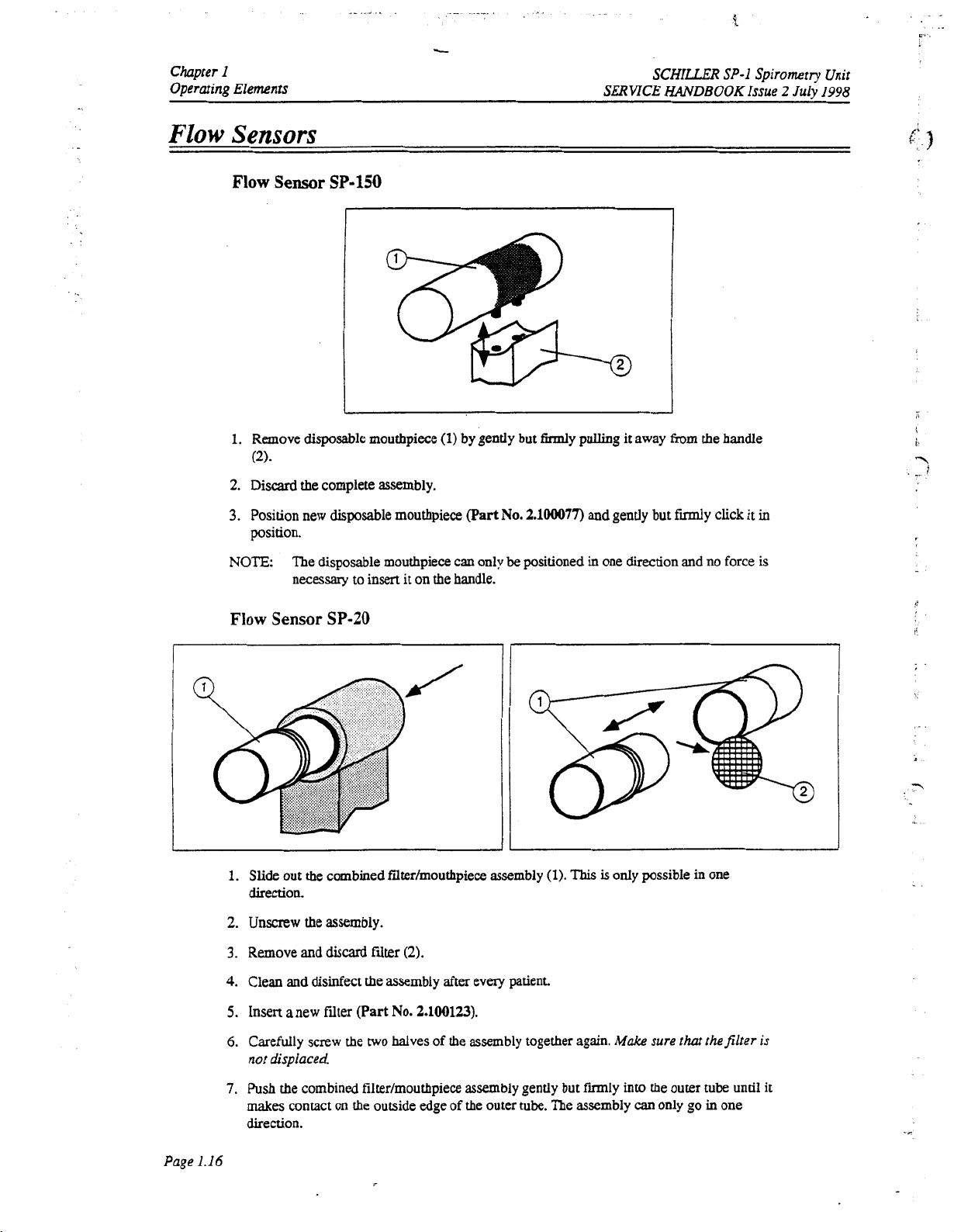
Sensor
1.
Remove disposable mouthpiece
(2).
2.
Discard
3.
Position new disposable mouthpiece
position.
NOTE:
SP-150
the complete assembly.
The disposable mouthpiece can only
necessary to insert it on the handle.
(1)
by gently but firmly pulling it away from the handle
(Part
No.
2.100077)
be
positioned
and gently but fdy click it
in
one direction and
no
force
in
is
d'
.
1
-.
Flow
Sensor
I
1.
Slide out
SP-20
the
combined filter/mouthpiece assembly
II
(1).
This
is
only possible
in
one
direction.
2.
Unscrew
3.
Remove and
4.
Clean
5.
Insert a new filter
6.
Carefully screw
not
the
assembly.
discard
Nter
and
disinfect the assembly after
(Part
the
two
displaced
(2).
No.
2.100123).
halves
every
patient.
of
the assembly together again.
Make
sure
that
thefilter
is
Page
1.16
7.
Push
makes
direction.
the combined filtedmouthpiece assembly gently but fmly
contact on the outside edge
of
the
outer
tube.
The assembly
into
the outer tube until it
can
only go in
one
Page 27

.-
SCHILLER
SERVICE
HANDBOOK
SP-I Spiromtly
Introduction
SPll-
Power Supply
CPU and Processing Circuits
Memory
Them1 Print Head Controller
Paper Mark
Power
Stepper Motor Controller
Issue
1
On
Unit
2
July
Reset
1998
Chapter
Functional
Contents
Chapter
Functional Overview
2
2
Overview
2.2
2.4
2.4
2.4
2.4
2.5
2.5
2.5
2.5
Page
2.
I
Page 28

Chapter
Functional
2
Overview
Introduction
SCHILLER
SERVICE
SP-I
HANDBOOK
Spiromtv
Issue
2
July
Unit
I998
..
This
Chapter
to
enable
modules.
provides a functional overview
the
service
engineer
A
functional block diagram supports the
to
identify
processing
of
the
SP-1
electronics. The
paths in
text.
order
aim
of
this
overview is
to
help iden@ possible faulty
Page
2.2
Page 29
SCHILLZR
SERVICE
HANDBOOK
SP-I
Spirometry
Issue
Unit
2
July
1998
Chapter
Functional
2
Overview
I
i
*
?
w
Page
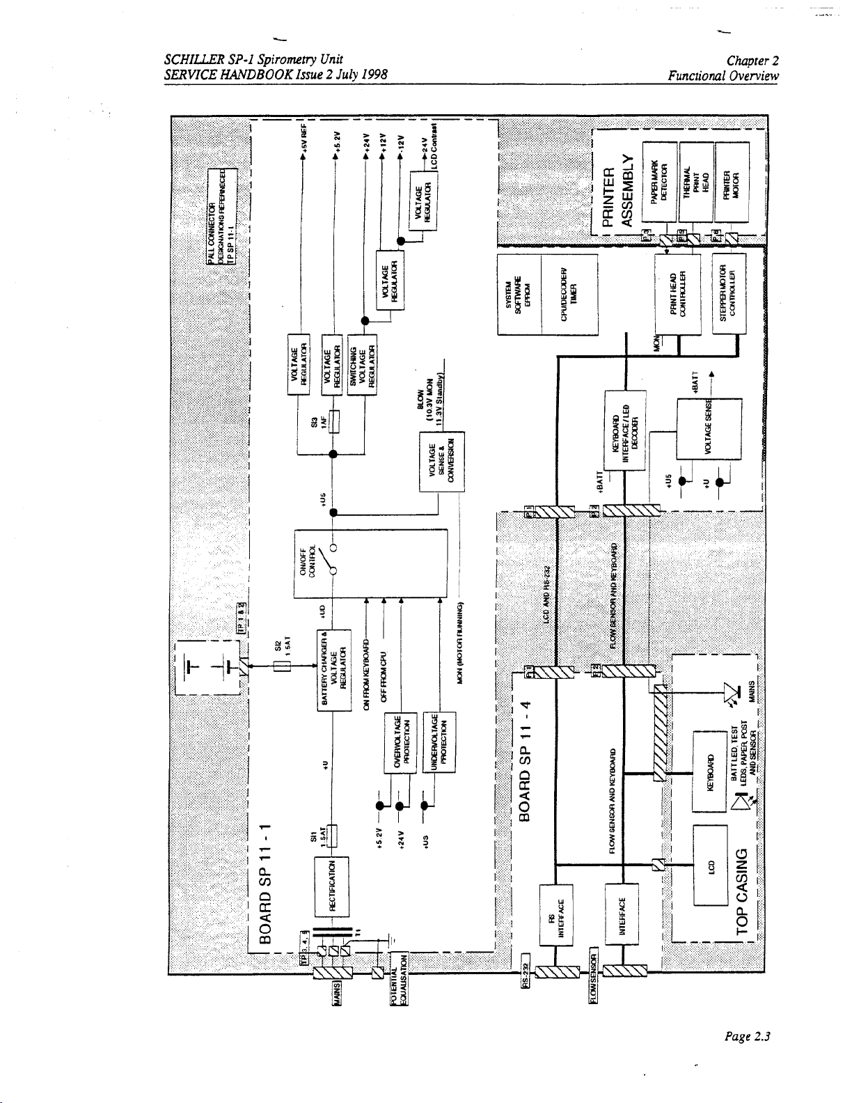
2.3
Page 30
Chapter
Functionul
2
Oveniew
\
SERVICE
c
SCHILLLB
HANDBOOK
SP-1
Issue
Spirometry
2
July
Unit
1998
SPll-
Power
The
1
Supply
mains
approximately
voltage generator
When
An
ON/OFF
directly from the keyboard
overvoltage
undervoltage
The mains
dc supply (+US) and activates signal
connected (i.e. the
A
Battery low signal
compensates
only
at
Note:
CPU
and
supply
is
full
15V
and
to
produce
mains
is
not connected,
control logic switches
on
either the
is
detected on
LED
is
lit
directly when mains
unit
(BLOW)
for
voltage drop when the printer stepper motor
1O.W.
The battery voltage is
off
(WFF)
Processing
wave
28 V
depending on
+UD
+UD
and
5.2V
+US
is
running on
is
rectified
or
also
to
produce
(13.5V).
is
the
battq
+UD
to
+m
an
unregulated
mains
voltage.
This
chges the battery when
voltage.
three
voltage
regulators.
voltage
then held on from the CPU (signal
24V
supplies directly switches
(indicating over current) the
is
connected. The same circuit
+BAIT
battery
generated when
monitored directly
when
power).
battexy
the
by
the
unit
is directly switched off.
unit is switched on and
voltage
(+US)
is
active and the Blow signal is active
the CPU which switches
when the voltage falls below approxhately
Circuits
dc
supply
(+W
of
between
is
used
by a switched
mains
is
connected.
The unit is switched on
WE).
unit
off.
also
monitors the switched
falls
Detection
Similarly when an
mains
to
11.3V.
A
the
9.4V.
is not
circuit
unit
of
-\
Overall control and coordination
of
the SP-1
Memory
Program Memory
An
EPROM contains the unit software. The EPROM
Static
The
battery backup for
Serial
The serial EEPROM
RAM
RAM
memory stores
EEPROM
Memory
data
retention when the unit is switched off.
(U12)
the
data
and comprises
stores the unit
is
base
by
68331CPU.
has
two
128
settings.
128kByte of memory.
kbyte
RAM
chips. The static
RAM
has
-.
.,
Page
2.4
Page 31

SCHILLER
SERVICE
SP-I
HANDBOOK
Spiroinetry
Unit
Issue 2 July
1998
Chapter
Functional Overview
2
SPII
-
I
Thermal Print Head Controller
The
Thermal
controller
applied
Print
serialises
to
the
head,
Head
the
and
Printer Timing
Strobe
generation
written. The first output
pulse 1ength.defined
passed through a decoder
Paper
Power
Mark
The Paper Mark
input to the comparator between approhtely
PMARK signal
On
Reset
The Power
follows:
To
provide a delay on
and
give the
is
aiggered
signal
is
logic
on
reset circuit controls the master reset of the CPU. This circuit
20Oms
is
controlled
data
for
thus
the
from
by
the
tempexam
to
set
from the printer is fed to a comparator. The paper
1.
initial
reset time required by the processor.
by
a
print head controller and timer
the print head and the
intensity
by
signal
4bit
STROBE
switch-on
of
the
TPS
when one complete pixel line
binary
counters trigger a monostable multivibrator (U37) at a
and resistance
1
signal.
to
ensure that the power supply
timer
printout.
of
the print-head
2.5
V
and 3.5V and when
circuit controls how long current is
circuit
The print head
of
data
is ready to
(TPHT).
mark
detection voltage
this
is present the
has
two
is
fully stabilized
be
The pulse is
functions
as
To
disable the
unit
if
the
+5V
rail
drops
Stepper Motor Controller
The printer stepper motor controller
dictated
The purpose
the Microprocessor is achieved and maintained.
by
the master CPU.
of
the stepper motor controIIer circuit
Paper Speed
25ds
(motor
sets
speed)
below
4.75V.
the speed of the printer motor with a clock frequency
is
to ensure that the motor speed requested
MCLOCK
Frequency
by
1.4kHz
Page
2.5
Page 32

.
.
f
c
.
.-
-
~
._
-..:
.
:r.
Chapter
Functional Overview
..
.
.
..
..
2
SERVlCE
SCHILLER
HANDBOOK
SP-I
Issue
Spirometly
2
July
Unit
1998
i
..
..
Page
2.6
Page 33

SCHILLER
SERVICE
SP-I
HAMlBOOK
Spiromm
Issue
Unit
2
July
1998
Fault
Chapter
Diagnosis
3
Introduction
Fault
Dingnosis
General
Calibrat5on
Service
Check
Screen
LCD Check
EEPROM
RS-232
Prinrer
Sensor
Check
Check
Flow
Chart
Procedures
Check
Check
Contents
Fault
Chapter
3
Diagnosis
3.2
3.3
3.4
3.5
3.7
3.8
3.8
3.8
3.13
3.13
Page
3.1
Page 34

Chapter
Fault
3
Diagnosis
Introduction
The
SP-1
is
designed to
1
ismodulereplacementandnotboardrepakThepurposeofthischapteris
procedures
procedures
An
finding
cases the
module
given
parameters
instructions for all replaceable modules. along with
given
that
are
initial
fault diagnosis chan
charts
fault
is
stated,
should
and
in
Chapters
be
simple
to
use
will
quickly and efficiently identify
designed
and
finding
.b
setfinpup
so
that
procedures
the
first
checked
4
and
on the following pages
charts
should indicate the most likely faulty area. When more
module given is the one most
in
the order given. When a module
of
5.
test
equipment
is
provided
the module
and
simple to
derailing
may
SCHILLER
SERVICE
is
kept
service:
a
to
the
service phiIosophy
toprovide fault-finding
fault
to a specific module. Fault-finding
a
minimum.
all the general fault indications.
to
indicate a
likely
faulty
area or module.
to contain the fault. Other modules
has
been replaced specific test
be applicable. The removal
any
setup or check
procedures
SP-1
HANDBOOK
Use
Issue
of
the
the fault
In
than
and
replacement
required,
Spirometry
2
Jury
1998
SP-
most
one
are
Unit
If the initial fault-finding
settings
and
parameters
that
chart
does
notindicate the
have been entered.
If
area
where the fault exists, re-check all the
these
are
correct, check the software.
Page
3.2
Page 35

SCHILLER
SERVICE
SP-I
Spirometry
HANDBOOKIssue
Unit
2
July
I998
Fault
Chapter
Diagnosis
3
Fault
Diagnosis
Chart
Page
3.3
Page 36

Chapter
Fault
Diagnosis
3
SERVICE
SCHILLER
HANDBOOK
SP-I
Spiromtry
Issue
2
Julv
Unit
I998
General
The procedure detailed here
boardhas been replaced. It
equipment
1
functional
information
relevant
To
carry
1.
Connect
2.
Switch the unit
and the welcome Screen
3.
Carry out the Printer Check
4.
Connect flow
5.
Carry out calibration
6
Carry out the
7.
Switch the unit
the battery.
8.
Disconnect the
unit on battery power for approximately
the
Check
User
out
battery has limited capacity (not before
Procedures
in
the factory) but
areas.
The
instructions
is
required
ManuaI
the general
mains
(general seaings, comprehensive menu guides em.) please refer
for
power
on
by pressing the
sensor
EEPROM
off
and leave connected
mains
is
a
general confidence check
isnotam
is
functional
intended
to
given
the
software
SP-1
functional check
to
the
unit
version
and
<ON>
is
displayed.
detailed
to
the
sensor
procedure
check detailed
and switch
in
connector
as
detailed in this chapter
the
unit
here
ensure
in
the unit
test (whichcan
provide ageneral confidence check
are
guides
to
the basic
applicable.
procedure,
that
key
on
this
chapter
on
in
this
chapter
to
the mains supply for
on.
Ensure that
an
hour. Ensure that the battery
45
minutes).
proceed
the
green
the keyboard.
the
side panel and switch on.
the
only
mains
Ensure
10
Battery
after
an
be
carriedout with
functions.
as
follows:
LED
lights.
that
hours or more
LED
internal module
dedicated
in
all
the major
If more
operating
the LCD lights
to
charge
is
lit. Run the
LED
flashes when
SP-
to
or
the
Page
3.4
Page 37

SCHILLER
SERVICE
HtWDBOOK
To
SP-I
Spirometry
Issue
calibrate, proceed
Unit
2
July
as
I998
follows:
-
Chapter
3
Fault Diagnosis
Last calib.
BTPS
Factor
Calib. Factor
Temperature
Measured
Syringe
Vol.
Vol.
23.1
1.090
1
.ooo
20
0.00
4.00
1.95
"C
I
I
IMPORTANT
THE
UNIT
MUST BE CALIBRATED
OF
THE DAY, AFTER EVERY SIGNIFICANT TEMPERATURE CHANGE OR
CHANGING
Last Calibration
BTPS
THE
SENSOR.
date of last calibration
Factory calculated
Saturated with water vapour) value.
difference in inhaled and exhaled humidity.
measuring exhaled volume
when inhaled volume is measured
ambient temperature to calculate the
for accurate
WITH
THE
FIRST
BTPS
(=>
Body Temperature, Ambient Pressure,
(100%
humidity, Temp 36.8"), and
this
FIVC
calculation. The formula used
PULMONARY FUNCTION
This
value
compensates for the
The
unit
factor
is
applied.
BTPS
factor.
This
is
as
is
set
for
The
SP-
is sufficient
follow:
TEST
AFTER
so
1
uses
Calibration Factor
Temperature
Measured Volume
Syringe Volume
273.15
+
BTPS
=
0.033
+
273.15
Tu
is
ambient temperature degrees centigrade
0.033
is
273.15
equivialent
is
degrees absolute
to
760mmHg
36.8
+
Tu
at
22 degrees
C
calculated value between measured and effective calibration
volume
ambient temperature in
air
volume measured by the system from the calibration pump
entered
air
volume depending on the size
times the
air
was pumped through
times amounts
pump is
4
litres;
to
6
litres
with
"C
(or
OF)
dependent on device setting
the
sensor, e.g. pumping 2 litres 3
(the
recommended volume with
3
litre
pump, 6 litres)
of
the calibration pump and
a
2
air
litre
Page
3.5
Page 38

f
..
-.
..
.
.,:
.
I.
..- -.
.:.-
Chapter
3
Fault Diagnosis
Calibration
Calibration
To
calibrate
Connect the calibration pump
Press the
The cursor
Press
ENTER
Wait 1 second.
Press the
Pump
4
Note:
While pumping, the unit records the volume being pumped
it on the display.
Make
Press the
Enter the pumped
litres).
The message "Calibration completed"
to
(cont.)
Procedure
the
unit proceed
CAL
key - the menu
is
positioned
when the correct temperature entered
START
to
6
litres
sure
STOP
the calibration pump and times
Press
ENTER.
obtain a printout
as
follows:
to
the sensor. Ensure
is
displayed
at
temperaaxe. Enter the ambient temperature
key
of
air
through
that
thejlow sensor
the'sensor
key when finished pumping.
air
volume at syringe volume prompt (depending on the size
of
the calibration report with the following information:
SCHILLER
SERVICE HANDBOOK Issue
that
there
are
no
air
leaks
as
shown on the previous page
is
kept still during the pumping operation.
of
pumping; i.e.
appears
through
a
on
the
flow
sensor
2
lirre pump pumped 3 times
the display, press the
SP-I
Spirometry Unit
and indicates
of
=
6
PRINT
key
2
July
I998
L
Page
Ifthe message
that
the difference between the measured volume andthe entered volume is
the
temperature sening, the syringe volume andthe entered syringe volume. rfthese are all correct
'EXCESSNE DEVMTION!
change the screedfilter and recalibrate
3.6
'appears
on
the screen after a calibration,
too
big
it
indicates
(>25%).
Check
Page 39

SCHILLER
SERVICE
SP-I
Spiromtry
HANDBOOK
Issue
Service Screen
To
check
the printer
To
carry
out
the
printer
Unit
2
July
and
I998
to
emure
check
press:
that
every
pixel is
operational,
a
built-in
printer
test
Fault
is
provided.
Chapter
Diagnosis
3
MENU
then press the
The following Menu options
LCD
EEPROM
RS-232
PRINTER
SENSOR
These are explained
following
on
keys simultaneously, in
the
following
key
ALT
are
then
-
given:
pages
select
MENU
<SETUP,
the
order given:
-PRE/POST
<DEVICE>
Page
3.7
Page 40

-
Chapter
Fault
3
Diagnosis
-
-
.-
-
c
SCHILLER
SERVICE
HANDBOOK
SP-1
Spirometry Unit
Issue
2
July
I998
c\
I
Service
LCD
EEPROM
RS-232
The following error messages
are
SERIAL
Screen
(cont.)
Check
Select
LCD
from
the
All
characters
screen
Press
any key. The designation
screen.
Return
pixels
All
keys
to
the
are
displayed. Select more characters with the up and down arrow keys.
can
be
can
service
service menu (page
checked
this
written
be
checked
menu by pressing the
m
way
this
7)
on
the key
way.
MENU
Check
Select EEPROM
The message 'EEPROM Working' is displayed.
On successful completion of the
Return
to
from
the
service
manu
(page
test
the
message 'EEPROM
the service menu by pressing the
7)
MENU
Check
are
associated with the
displayed,
carry
LINK
out the checks suggested.
TIME-OUT
This
indication appears
remote unit
(after
is
displayed on the right hand side of
key
okay'
is displayed
key
RS
Interface. If any
if
approximately
no
of
these error messages
signal
is
received
30
seconds).
All
from
(3
the
\
>
the
TRANSMISSION ERROR
NO
DATA
0
Check
that
the remote unit is switched on and set
correct parameters
0
Check the correct setup
0
Check that the connecting cable
0
Check the integrity of the cable assemblies (at both
units)
0
If
using a modem ensure
the remote modem
This
is
a
general fault indication
Check
that
0
cmect parameters
0
Check that the connecting cable
0
Check the integrity of the cable assemblies (at both
the remote unit is switched on and set
in
both units
that
it
is
is
correctly plugged in
communicating with
is
correctly plugged
units)
0
Ifusing amodem, ensure
the
remote modem
A
transnission
the
units'
and attempt the transmission again. If the
appears, change the processor board.
has
been
memory. Store a measurement in the memory
that
it
is
communicating with
attempted, but
no
data
same
is
stored
message
to
to
the
i
the
in
in
Page
3.8
Page 41

SCHILLER
SERVICE
SP-1
HANDBOOK
Spirometry Unit
Issue
2
July
1998
Chapter
Fault Diagnosis
3
Service
RS-232
When
changed
The test uansmission I test reception options enables
Use these test options to ensure that the receiving and transmitting
the
The test message generated
the
unit are displayed
indicating that a test transmission
To perform these tests, you will need a second
connected to
95TM.
Screen
(cont.)
Check
RS-232
cable assemblies, connectors etc. between
test
The following equipment
A
personal computer
is
by
pressing the
selected,
the
screen
START
is
asuing of
key
transmission I reception option
on
the LCD in the receiving unit.
is
in progress.
an
active terminal, for example the
is
needed:
(PC)
with Windows
shows
and
the parity by pressing the
all
ASCII
is
selected,
the Baud
rate
a
test
sequence to
the
communicating
and the parity.
characters - ABCD....
the
string
of
In
the transmitting unit amessage
SP-1
unit, or the
Hyperterminal,
95TM
Hyperterminal
PRINT
be
units
units
characters
SP-1
RS-232
which
is
installed.
The
Baud rate
can
be
key.
generated and received.
can
communicate and that
are
good.
12
34....
abcd...
etc.
When
sent by
the
transmitting
is
displayed
interface
has
to
be
available under Windows
An
1.
RS-232
SP-1
and
Start
cable assembly,
with the
an
COM
adapter DB
from Windows
Art.
port
of the
9
I
DB
25,
Art.
95
desktop. Click on
Hyperterminal.
2.
Double-click on Hypertrm(.exe). Enter
OK.
No.
PC.
No.
2.310 159.
This
assembly consists of a cable,
2.100 552.
the
for connecting the
START.
name
Select Programs I Accessories
SP-1
for the new connection
RS-232
Art.
interface on the
No.
2.310 094
I
and
click on
Page
3.9
Page 42

Chapter
Fault
Diagnosis
3
SERVICE
SCHILLER
SP-I
HANDBOOK
Spirometry
lssue
2
July
Unit
1998
.-
Service
3.
4.
Screen
Set
the
Enter the port settings
(cont.)
direct connection
to
the proper COM-port
19200,8,
N,
1,
Hardware
and
click
OK.
and cont-irm with OK..
P
Page
3.10
5.
You
are now
6.
Go
to tab Settings and
7.
Click
on ASCII
in
the
SP-1
Setup.
Hyperterminal window. Click on File
set
Terminal keys.
Auto
detect
and
and
500
buffer lines.
select Properties.
Page 43

--.
SCHILLER
SERVICE
1
Service
SP-I
Spirometry Unit
HANDBOOK
Screen
8.
Check the boxes for "Send line ends with line feeds",
"Wrap lines that exceed terminal width". Confum with
back
to
the open
Issue
2
July
(cont.)
Hyperterminal
I998
window.
"Echo
typed
OK.
Click once more on
Fault Diagnosis
characters locally" and
OK
to
get
Chapter
3
You
are now ready
Test
Output
On the
SP-1,
N,
stopbit
Press the
The
SP-1
Hyperterminal window on
!"#$~6'()*+,-./0123456789:;<=~?dABCDEFG~JOP~RsT~Z[\]A~'abcdefghijk~o
pqrstuvwxyz(
'absdsfghijkknnopqrttuvwxyr(
POR3TUWXYZ[\]A'_'abcdefghijkLnnopqrstuvrxy
to
start
the
select
the
RS-232
1.
UP
key
A
now sends a suing
I
)-I3
!
"#$86*
()
input and
of
the
*+,-./0123456789:;~>79ABCDEPGHI~OP9R3T~Z[\]*_
11-0
output
tests.
screen,
and
make
sure
that the settings
alphanumerical characters, which are
are
19200
echoed
bps, parity
in the
PC.
1"#$OC'()*+,-./0123456789:;~~>?BABCDEPGHI~O
Stop
the
test by pressing
the
STOP
key.
Page 3.11
Page 44

Chapter
Fault
Diagnosis
3
SERVICE HANDBOOK
SCHILLER
SP-1
Spirometry
Issue 2 July
Unit
1998
Service
Test
For
be
The following pins
1.
2.
3.
Screen
(cont.)
Input
this
test
a
SCHILLER
fabricated
from
a
standard 9-pin
must
pins 2 and 3 (receive
pins 7 and
pins
Connect the
Select the
Press consecutively the
output
and
6
and
R3
test
RS-232
confm
8
(RTS
4
@SR
plug
test
that
RS-232
be
wired:
/
/
CTS)
/
DTR
to
the
window.
UP
A
some
test
plug
is
needed.
D-type
plug.
rrausmit)
(ready))
RS
port
on
the
and
DOWN
characters
are
If
SP-1.
echoed
such a plug
keys
on the screen
is
to
toggle between
not
available,
it
can easily
in-
and
c
I,-
-
4.
Leave the
Rs-232
test window by pressing the
MENU
key
twice.
.
Page
3.12
Page 45

SCHI..
SERMCE
WDBOOK
SP-1
Spirometry
Issue
Unit
2
July
1998
Chapter
Fault
Diagnosis
3
.I
-?
Service Screen (cont.)
Printer
Check
Select
PRINTER
Various
Press the PRINT Key (when
Return
Carefully examine
pixeis wiU
If afaultypixelis
at
the top
is
too
been
quality.
IMPORTANT:
to
be
than
faint
or
exposed
printer
too
from the service manu @age
dam
the
service
the
printout and ensure that
seen
as
a
horizontal white line. Examine the printout for evenness
detectedtheprintermustbereplaced.
at the bottom), it indicates that the printer &pent
dark,
check the
to
light
for a long
7)
is
given. Ensure that the temperature reading
still
in
the Printer
menu by pressing the
strok
adjustment.
period,
or
THE
'SHELF
INDEFINTIE. OLD
STORED
THAT
ADVERSELY
RECOMMENDED
IN
HAS
LIFE'
A COOL
BEEN
EFFECT
service
MEMJ
all
poor
OF
PAPER, PAPER
EXPOSED
TO USE
key
the
lines
are
If
the printoutis uneven (for example darker
Also
check the
quality
paper
THE
PRINTER PAPER
DAMP
FREE ENVIRONMENT,
TO EXCESSIVE HEAT
THE
QUALITY
ORIGINAL
screen)
even and uninterrupted. Any faulty print-head
can
THAT
is
ambient
-
a
test printout is given.
is
not
pap,
old
all
adversely effect the print
HAS
OF
THE
SCHILLER PAPER.
k
5
of
print.
correct.
If
the printout
paper, paper that has
IS
NOT
NOT
BEEN
OR PAPER
CAN
PIUNT.
degrees.
IT
IS
Print
Head Alignment
The print head tension (the pressure that the print head exerts on the printer paper)
two spring exerting pressure on the print head: the print head tension cannot be adjusted. Similarly
print head alignment is fixed and cannot be adjusted.
alignment is not correct change the paper tray
Sensor
Flow
Check
Select SENSOR from the service
The
Analog /digital value
Return
to
the service menu by pressing the
and Print
manu
is
given. Ensure
Head Tension
If
and
printer assembly.
(page
7)
that
the value is
MENU
key.
is
achieved
the print head tension or print head
2042
k
10
with
Page
3.13
Page 46

*”
.
Chapter
Fault
Diagnosis
3
SERVICE
SCHILLER
SP-I
HANDBOOK
Spirometry
Issue
2
July
Unit
I998
Page
3.14
-
Page 47

SCHILLER
SERVICE
HANDBOOK
SP-I Spirometry Unit
Issue
2
July
I998
Module Removal
Chapter
and
Replacement
4
Chapter
4
Module Removal and Replacement
Contents
Introduction
Safety Notices
Physical Overview
Tools,
Test Equipment,
Opening the Case
Top Assembly Removal
Top Assembly Replacement
Flow
Sensor
/
RS
Board Removal
Board Replacement
Checks and Tests afer Replacement
Battery
Printer
Control and Power Supply
Keyboard
Pack
Battery Pack Removal
Battery Pack Replacement
Checks
and
Tests Afrer Battery Replacement
Tray Assembly
PrintedPaper tray Assembly Removal
l3ermal Printer Removal
Thermal Printer Replacement.
PrintedPaper tray Assembly Replacement
Checks, Tests and Adjustments afrer Printer Replacement
Board Removal
Board Replacement
and Accessories
Interface
and
SP
11-4
Thermal
board
SP
printer
II-1
4.3
4.4
4.5
4.6
4.7
4.7
4.8
4.9
4.9
4.9
4.9
4.10
4.10
4.10
4.10
4.11
4.12
4.12
4.12
4.12
4.12
4.13
4.13
4.14
4.15
Page
4.1
Page 48

Chapter
4
Module Removal
and
Replacement
ai
BASE
ASSEMBLY
-
10:
ACCESS
SCHILLER
SERVICE
HANDBOOK
-
SP-I
Spirometry
Issue 2 July
Unit
1998
Page
4.2
Note:
The
Program
ai
TOP
ASSEMBLY
EPROM
To:
is
ACU3-S
mounted
on
the
Control
and
Power
Supply
board
SP
r
11-1.
Page 49

SCHILLER
SERVICE
SP-1
Spirometry
HANDBOOK
Introduction
This
chapter
spared
containing the following:
The prerequisites
provides
at
service level. The
Unit
Issue 2 July
an
overview
that
must
1998
insmctions
be
of
the
fulfiued
\
procedures
given in
this
to
remove and
chapter
are
autonomous, with
before removing of the module
Chapter
Modrrle Removal and Replacement
replace
the modules
each
that
are
module
.-
~
L
4
Tools and equipment
that
are requited
the functional checks and adjustments
Removal Procedures
Replacement Procedures
Checks and Tests
Any
adjustments, jumper settings,
that
must
be
carried out
special
a procedure, are detailed in the relevant
In-text
diagrams
support
the
text where required and provide location details of connectors, test
points and adjustment potentiometers.
are
Specific warnings and cautions
could
cause
personal injury. Cautions indicate
If
a key operation or menu selection
.o’.
The character (or character string) given
a
on the key. When
key sequence is provided
given where applicable. Warnings indicate potential danger that
is
required, the key sequence required is given
to
remove and replace the module and
after
replacement
to
carry out
checks or functional procedes that are requirer
step.
areas
that
could cause damage to the equipment.
in
parenthesis
in
parenthesis is the actual character
it
must
be
followed
in
the order given.
that
is
printed
Page
4.3
Page 50

Chapter
Module Removal
4
and
Replacement
SCHILLER
SERVICE
HANDBOOK
SP-1
Spirometry Unit
Issue
2
July
1998
Safety
CERTAIN CHECKS
ASSEMBLY
THESE PROCEDURES BEWARE THAT POTENTIALLY LETHAL VOLTAGES
THE
PRECAUTIONS:
0
UNIT ON
Notices
WARNINGS
BEFORE COMMENCING
THATTHE
IS REMOVED.
MAINS
REMOVED
PRESENT.
SP-1 CONTAINS STATIC SENSITIVE CMOS COMPONENTS; OBSERVE ANTISTATIC
WHEN
CARRYING
AN
EARTHED ANTISTATIC MAT.
ANY
REMOVAL
POWER SUPPLY IS SWITCHED
AND
ADJUS"TS
AND
WITH
OR REPLACEMENT PROCEDURES
CAN ONLY BE CARRIED
MAINS
CONNECTED.
CAUTIONS
OUT
ANY
MAINTENANCE PROCEDURES ALWAYS PLACE
OFF
AND
THAT
WHEN
THE
MAINS
OUT
WITH
CARRYING
ENSURE
CABLE
THE
TOP
OUT
ARE
THE
0
PERSONNEL MUST BE EARTHED WHEN HANDLING ANY BOARDS OR
COMPONENTS
0
ALWAYS
USE
AN ANTISTATIC BAG WHEN TRANSPORTING BOARDS OR
c0MPo"Ts
THE
UNIT
IS SUSCEPTIBLE TO ABRASION DAMAGE. TO PREVENT SCRATCHING,
ALWAYS PLACE
OUT
MAINTENANCE PROCEDURES.
TAKE
CARE NOT TO PLACE
WHEN
NOTCRIMPED ORTWISTED ANDTHATTHETOP ASSEMBLY IS NOTPLACEDONTHE
CABLE ASSEMBLY.
CARE MUST BE TAKEN
USE FORCE.
THE
ORDER GIVEN.
REMOVING
PROCEDURAL STEPS GIVEN
THE
THE
NEVER
UNIT
ON A
SOFT,
ANY
TOP ASSEMBLY.
WHEN
REMOVING
STRAIN
THE
CABLE
FOR
NON-ABRASIVE CLOTH WHEN CARRYING
STRAIN ON
EACH
THE
CONNECTING RIBBON CABLE
ENSURE
AND
ASSEMBLIES.
THAT
THE
CABLE ASSEMBLY IS
REPLACING CONNECTORS.
MODULE MUST BE FOLLOWED IN
NEVER
THE
Page
4.4
Page 51

SCHILLER
SERVICE
SP-I
HANDBOOK
-
Spirometry
-
Issue 2 July
Unit
I998
Chapter
Module Removal and Replacement
4
Physical
The
The
the thermal printer, the paper
The electronics
board
in the base section.
The
spacers.
The
base
Because
screw
Overview
SP-1
unit
is
enclosed
top
part
contains
of
the
SP
11-1
and Flow sensor and
battery
is
secured
'
thermai
printer is mounted on a
section complete.
of
the plastic construction
fixings.
in
a
two
part,
medical
the keyboard with the
tray,
the battery and
unit
are
in
position
contained
RS
with
papex
of
on
board
double
the
standard,
base
section
two
printed
SP
114).
sided
trayhhermal printer assembly which
case,
threaded metal inserts are
containing
mains
aansfomer.
circuit
The
tape
and the
moulded
KBs
plastic
case.
all
the electronics
board
(control and power supply
are secured on spacers moulded
mains
transformer
used
of
the
is
secured
is
secured
throughout for
in
uniL
on
the
all
Page
4.5
Page 52

.
Chapter
Module
-. . . .
4
Removal
and
Replacemem
.c
SCHILLER
SERWCE
SP-I
HANDBOOK
Issue
Spirometry Unit
2
Julv
I998
?
Test Equipment, Tools,
.
,l
,
The following list
functional tests, calibration procedures and adjustments
test equipment given here is general.
details
the
and
Accessories
tools,
test equipment and accessories required
that
can
be
If
specifc
recommendation
carried out on the
for
test
equipment is required,
to
carry out
SP-1.
The
all
please contact the SCHILLER service department.
Digital
Voltmeter
oscilloscope
Frequency Counter
Selection
Cleaning agent such
of
&oss-bladed, posi-drive and flat-bladed screwdrivers
as
Tricoetholine
Selection of spanners
Double-sidedtape
Page
4.6
Page 53

SCHILLER
SERVICE
HANDBOOK
SP-I
Spirometry
Issue
Unit
2
July
I998
Chuprer
Module Removal and Replacement
4
Opening
Prerequisites
The
maintenance is carried out on the SP-1. The room temperature should
degrees.
THE
BE
Tools
Posi-drive screwdriver
Test Equipment
The following test equipment
flowsensor
calibrationpump
Top
Assembly
The Top Assembly
six
screws; access
Assembly, proceed
the
Case
unit
must
be
WARNINGS
OBSERVED.
Removal
placed on an antistatic
AND
CAUTIONS AT
is
required
is
mounted on the
to
the screws
as
follows
Base
is
gained from the underside of the
mat
and antistatic precautions observed when any
be
between
THE
BEGINNING
to
carry
out the functional test after unit assembly
Assembly and
is
OF
THE
CHAPTER
secured to the Base Assembly with
unit.
To remove the Top
18
and
MUST
28
W
A
1.
Turn the
WING
ENSURE
unit
upsidedown and rest on a soft antistatic cloth.
THAT
THE
MAINS
:
CABLE
IS
II
2.
Unscrew and remove the
extreme comers and edges
4.
Grasping the top and bottom
carefully
5.
Gently
disconnect the cable assemblies between the flow sensor board SP
and between the flow sensor
6.
Gently lift the Top Assembly away from the
return
the
lift
the Top Assembly sufficiently
six
countersunk retaining screws and washers situated
of
the
of
the unit to ensure
unit
to
the standing position.
board
unit.
SP
to
gain access
114
and the
that
the
two
to
LCD.
Base
Assembly and place on a soft cloth.
REMOVED.
ll
in
assemblies cannot pah
the
interconnecting cables, and
11-4
and
the
keyboard,
the
Page
4.7
Page 54

..
.
.
Chapter
4
Module Removal
and
Replacemenr
.
..
SP-I
SCHILLER
SERVICE
HANDBOOK
Spirometry Unit
Issue 2 July
I998
.
-_I
I.
I
..
.....
._'
:-
'
-:
Opening
..
Top
the
Assembly
To
replace
1.
Check
that
no
2.
Inspect
no
visible damage
Caught.
3.
Ensure
4.
Position
Case
the
Top
that
all
screws
all
the
that
all
the
(cont.)
Replacement
Assembly proceed
boards
and components
or
foreign
bodies
internal
Top Assembly
cable assemblies and
can
be
seen.
connectors
are
in
Ensure
fdy home.
front
cable, plug in the interconnecting cables
sensor board SP
Note:
It may
5.
Carefully position the Top Assembly
6.
Grasping
upsidedown and replace the
edges of the unit. Return the
114
be
necessary
the
two assemblies
to
tilt
to
ensure that they cannot part, carefully
six
securing screws and washers
unit
as
follows:
are
fdy
secured.
are
loose
in
the boaom
ensure
that
that
no
cable
assemblies
of
the
Base
Assembly and without straining the ribbon
from
the Keyboard and from the LCD
the Top Assembly for
on
the
Base
Assembly.
to
the upright position.
Check
of
the
they
the
for
loose
screws.
case.
are
in
good condition and
are
strained,
cable
assemblies to reach.
in
the extreme comers and
turn
crushed
the
to
unit
Ensure
that
or
the
Flow
-1
.;
,
i.
7.
Carry out the
Exploded
See
Circuit
View
Diagrams
functional
check procedure detailed
and Board Layouts
Section.
in
Chapter
3.
1
Page
4.8
Page 55

SCHILLER
SERVICE
HANDBOOK
SP-I
Spirometry
Issue
-
Unit
2
July
1998
Module Removal
Chapter
and
Replacement
4
Flow
Sensor
The Flow sensor
11-1
Prerequisite
The Warnings and Cautions
The Top Assembly must
Tools
Cross-bladed posi-drive screwdriver
Parts
Row
Board Removal
THE
COMPONENTS.
To remove the
1.
1
and
is
secured
and
Test Equipment
sensor
/
RS
FLOW
Unscrew the
SENSOR / RS
board
RS
Interfuce
/
RS
Interface
to
six
Interface board Part number
board
spacers.
at
the beginning
be
removed and
SP
is
mounted above the Conaol and Power Supply board
aU
CAUTION
INTERFACE
OBSERVE
proceed
six
screws securing the board
ANTISTATIC PRECAUTIONS.
as
follows:
11-4
of
the Chapter must
external
BOARD
cable
as
detailed
CONTAINS STATIC
to
the spacers.
be
observed.
assemblies disconnected.
in
Chapter
6.
SENSlTIVE
SP
CMOS
2.
Gently
raise
the
board
to
gain access
the two connectors. Remove
the
to
the cable assembly
board.
Board Replacement
1.
Place the flow sensor and
the
cable assembly
connector and the
2.
Secure the board
to
RS
board
to
the Control board SP
RS
connector
the
six
are
spacer
supports
component side down over the six spacers and connect
positioned in the cutouts on the side panels.
Checks and Tests after Replacement
To prove the integrity
1.
Switch on the unit and connect a Flow sensor.
2.
Carry out the calibration procedure detailed in Chapter
of
the replaced
board
to
the
Control
11-1.
Place the
with the retaining screws.
carry out the following functional check procedure:
3.
board
so
that
board
and remove
the
flow sensor
Page
4.9
Page 56

E
I
--
Chapter
Moa'ule Removal
.
Battery Pack
4
and
The batcery
Replacement
pack
is held
in
position with double
sided
tape.
SCHILLER
SERVICE
HANDBOOK
SP-I
Spirometry
Issue
2
July
Unit
I998
i
Prerequisite
The
Warnings
The
Top
and
Cautions
Assembly must
at
the
be
removed and
beginning
all
of
the
Chapter
must be
observed.
external cable assemblies
disc~~e~ted.
Parts
The
part
numbers
of
all
replaceable items
are
given
in
Chapter
6.
Battery Pack Removal
WARNING
THE
MAINS
To
remove the Battery Pack proceed
1.
Ensure that the unit
SUPPLY
MUST
BE DISCONNECTED
as
is
switched
off
and
follows:
that
the
DURING
mains
is disconnected.
THIS
PROCEDURE
2.
Disconnect the two bayonet connectors and remove the Battery Pack by gently pulling
away from
the
base.
Battery Pack Replacement
1.
Position the Battery Pack with the connectors towards the inside of
2.
Remove the double-sided
3.
Connect
Checks
Program
the
and
Tests After Battery Replacement
all
static settings which
bayonet connectors.
tape
protective sheet and secure the Battery Pack
will
have been
lost
when
the
battery was disconnected.
the
unit.
to
the base.
_-
Page
4.10
Page 57

SCHLLLER
SERVICE
HANDBOOK
SP-I
Spirometry
Issue
Unit
2
July
I998
Module Removal
Chapter
ad
Replacement
4
Printer
Prerequisite
Tools
Part
The part numbers for the Thermal
Chapter
THE THERMAL PRINTER
PRECAUTIONS
Tray
The
Assembly and Thermal printer
Warnings
and Cautions
The Top Assembly must
be
must
disconnected.
Cross-bladed screwdriver
Flat-bladed screwdriver
Flat
ended pliers
Numbers
6.
at
the
beginning
be
removed
Printer
CONTAINS
of the
Chapter
as
detailed previously.
must
be
observed.
All
external cable assemblies
Assembly, the print head and the motor are given
CAUTION
IS
STATIC
SENSITIVE;
OBSERVE ANTISTATIC
in
COG WHEEL
4.430 118
AND
ROLLER
BEARING
PRINTER PAPER MARK DETECTOR
ROLLEF
4.41
L
18
1
p
I
MK
11-51
PRINTHEA
4.140
115
3.2423BA
TENSIONING SPRINGS
PRINTER MOUNTING PLATE
MOTOR
PRINTER PIVOT
SECURING WASHER
4.330 019
(X2)
AND
Page
4.1
I
Page 58

Chapter
Module Removal
4
and
Replacement
SCHILLER
SERVICE
HANDBOOK
SP-1
Spirometry
Issue 2 July
Unit
I998
.->
i.
..
Printer
Tray
Assembly and Thermal Printer
Printerpaper tray Assembly Removal
1.
Remove the following connectors from the Control and Power Supply
data
2.
Unscrew
connector
earth connector
paper
mark
prinm motor connector
the
four
to
the thermal printer
to
the
connector
retaining screws
Thermal Printer Removal
1.
Turn
the
Paper my/printer assembly upsidedown and unscrew the two retaining printer
retaining screws.
2.
Gently remove the
printer
taking
Thermal Printer Replacement.
To replace the Thermal Printer
1.
Position
slot into the dedicated cutouts in
that
strained.
the
Printer in the paper my/print assembly
the cable assemblies from the printer to the Interface PCB are not caught and are not
printer
care
proceed
the
(cont.)
board
SP
11-1
:
and
remove
to retain the
as
follows:
assembly; secure with the two retaining screws. Ensure
the
complete paper my/printer assembly.
two
tensioning springs.
so
that the printer mounting plate lips
2.
Using a spring compressor, insert the
positioned over the moulded spring supports and
mounting plate.
two
tensioning springs
in the
so
that the springs are
indent (hole)
Printerpaper tray Assembly Replacement
1.
Position and secure in the
2.
Reconnect the following connectors to the Control and Power Supply board
data
connector
paper
mark
earth
COM~C~M
printer motor connector
3.
Replace the Top Assembly.
base
to
the thermal printer
connector
to
the printer
the assembly
with
the four retaining screws.
Checks, Tests and Adjustments after Printer Replacement
Check the print quality
as
described
in Chapter
3.
in
the printer
SP
11-1
:
Page
4.12
Page 59

SCHILLER
SERVICE
HANDBOOK
SP-I
Spirometry Unit
Issue 2 July
I998
Chapter
Moahle Removal and Replacement
4
Control
The Control and Power Supply
Flow sensor and
Prerequisite
Tools
Posi-drive screwdriver
Parts
Control and Power Supply bard
Board
and Power
RS
The
Warnings
The Top Assembly must be removed and all external cable assemblies disconnected.
The Flow sensor and
The Printer Tray Assembly
and
Equipment
Supply
board
SP
114.
and Cautions
RS
board
board
board
SP
at
the beginning
SP
114
must
be removed.
SP
11-1.
SP
11-1
11-1 is secured to the base
of
the Chapter must
must
be
removed.
Part number
as
detailed in Chapter
tray
and positioned under the
be
observed.
6.
Removal
WARNING
ENSURE
To
remove the Control and Power Supply board
1.
Disconnect the following connectors:
Tip
Note:
2.
Unscrew the nine spacer
T&e
THAT
THE
MAINS
live and the neutral bayonet connectors to the battery
data
connector to the thermal printer
paper
mark
connector
earth connector to the printer
printer motor connector
live and the neutral bayonet connectors to the mains connector
!
It
may
be easier
this case disconnect
The two connectors to the flow sensor and
as
detailed in the previous paragraph.
mains transformer is fured
CABLE
to
remove the
the
fmtions
ground
(four
to
the
IS
DISCONNECTED
SP
11-1 proceed
mains
connector togethr with
lead
from
the
potential equalisation stud.
RS
on the
mains
board
with
double-sided
BEFORE
as
board will already have been removed
transformer) and remove the
COMMEFJCING
follows:
the
control
board.
board.
In
tape.
Page
4.13
Page 60

Chapter
Module
4
Removal
and
Replacement
SCHILLER
SERVICE
HANDBOOK
SP-1
Spirometry Unit
Issue
2
July
I998
-
$0
Control
and
Board Replacement
To
replace
1.
Position
2.
Connect
3.
Replace the
reassemble the
Power
the
Control
the
board
the
following:
live
and
connector
live
Bnd
data
connector to the thermal printer
paper
mark
earth connector
printer motor connector
Flow
Supply
and
Power
Supply
and
secure
at
the neutral bayonet connectors to the
to
the
potential
the neutral bayonet connectors to the battery
connector
Sensor / RS Interface
unit.
board
board
the nine
equaIisation
fixing
SP
11-4
SP
SP
11-1
proceed
points ( four
mains
stud)
(detailed
11-1
(cont.)
as
follows:
on
the
mains
transformer)
connector
in
the previous paragraph) and
(or
the
i
3
ground
-
\
7
L
Page
4.14
Page 61

.-
-
. . .
. .
,,
.
-.
.
SCHILLER
SERVICE
SP-I
Spirometry
HANDBOOK
Issue
Unit
2
July
I998
Chapter
4
Module Removal and Replacement
Keyboard
The keyboard comes
keyboards
.
-.
are
as
given in
acomplete assembly
Chapter
6.
with
the
top casing. The
parts
numbers
of
the
various
Page 4.15
Page 62

-
Chapter
Module
4
Removal
and
Replacement
SCHILLER
SERVICE
HANDBOOK
SP-I
Spiromtv Unit
Issue
2
July
1998
Page
.:
4.16
Page 63

SCHILLER
SERVICE
HANDBOOK
SP-I
Spiromety Unit
Issue
2
July
I998
L
Chapter
5
Adjustments
3-c.
.*
x
;
..
...j
'
:
,
.j
Chapter
5
Adjustments
Contents
Introduction
Safety Notices
Conditions
Test Equipment
Proprietary Test Equipmen
Test Setup
Board
SP
11-1
Con&ol
Ba#ery Charge Volhge
Component Location
Precautions and Requirements
Tools
and
Equipment
Procedure
Paper
mark
Detector
Tools,
Equipment
and
Material
Procedure
flools
5.2
5.3
5.3
5.4
5.4
5.5
5.6
5.7
5.7
5.7
5.7
5.8
5.8
5.8
Page
5.1
Page 64

Chapter
Adjustments
5
Introduction
This
Chapter
procedure
equipment
required
In-text
points
is
necessary.
on
the
diagrams
and adjustment potentiometers.
provides the
prccedures
necessary
to
check
self-contained and details the mls required
Any
module,
support
adjustments,
or on
associated
the text
where
jumper
settings,
modules
required
and provide location details
or
software,
special
SCHILLER
SERVICE
and adjust
to
carry
all
out adjustments, and the test
checks or functional
are
also
detailed
SP-I
Spirometry
HANDBOOK
Issue
service settings. Every
tests
that
are
of
connectors, test
2
July
Unit
1998
Specific warnings
The
part numbers for
The SP-1
has
and cautions
all
are
given
replaceable modules
the following adjustments:
in
the text
are
given
where
in
applicable.
Chapter
Battery Charge Voltage (VR1 on the Microprocessor/Power supply
Paper
Mark
Detector
(VR2
on
the MiaoprocessorPower supply
6.
Board
Board
(SP
(SP
11-1))
11-1))
Page
5.2
Page 65

SCHILLER SP-I
SERVICE HANOBOOK
-,.
. .
.,
....
.
Safety
Spirometry
Issue
Notices
Unit
2
July
1998
Chapter
Adjustments
5
WARNING
MAINS
DISASSEMBLING
DISCONNECTED BEFORE CARRYING
CHECKS, OR
POWER
IS POTENTWLY
ADJUSTMENTS.
THE
UNIT.
LETHAL - DISCONNECT
ADDITIONALLY
OUT
ENSURE
ANY
MAINTENANCE, CALIBRATION,
THE
THAT
MAINS
THE
BEFORE
MAINS
CAUTIONS
THE
SP-1 CONTAINS STATICSENSITIVECMOS
PRECAUTIONS.
PLACE
EARTHED
ANTISTATIC BAG
CARE iMUST BE TAKEN
USE FORCE.
THE PROCEDUR4L STEPS GIVEN FOR EACH MODULE MUST BE FOLLOWED IN
ORDER GIVEN.
THEOUTERSURFACES OFTHE SP-1
PREVENT SCRATCHING, ALWAYS PLACE
THE
WHEN
UNIT
WHEN
NEVER
CARRYINGOUT
ON
AN
EARTHED ANTISTATIC MAT. PERSONNEL MUST BE
HANDLING
WHEN
TRANSPORTING
WHEN
STRAIN
THE
ANY
BOARDS OR COMPONENTS. ALWAYS USE
REMOVING
CABLE ASSEMBLIES.
ARESUSCEFTIBLETOABRASIONDAMAGE.
C0MPO"TS;OBSERVEANTISTAllC
ANYMAINTENANCE
BOARDS
AND
ON
OR COMPONENTS
REPLACING CONNECTORS. NEVER
A
SOFT,
PROCEDURES ALWAYS
NON-ABRASIVE
CLOTH.
IS
AN
THE
TO
Conditions
The
unit must
maintenance
The
room
Note:
be
placed on an antistatic
is
carried out on the
temperature should
a
When
key operation or menu selection
SP-1.
be
between
mat
and antistatic precautions observed when any
18
and
28
degrees.
is
required in the following procedures, the
key sequence required is given in parenthesis
string, given
in
parenthesis is the actual character, or character string, printed on
key.
-0'.
The character, or Character
the
Page
5.3
Page 66

Chapter
Mjustments
5
-
SCHILLER
SERVICE
-
SP-I
HANDBOOK
Spirometry
Issue
2
July
I-
Unit
1998
Test
Proprietary
Equipment
The following proprietary
board checks and adjustments on the
The
list
of proprietary equipment
test
equipment
can
Test
0
oscilloscope
0
DigitalMultirneter
0
Standard
pliers and general
0
FlowSensor
tool
kit
and
dedicated
be
obtained from the
Equipment/Tools
with a selection
tools
test
equipment
is
required to fault find and cany out
SP-1.
is
not comprehensive. Recommendations of suitable proprietary
SCHlLLER
of
cross-bladed, flat-bladed and psidrive screwdrivers,
Service
Department
!-)
all
Page
5.4
Page 67

SCHILLER
SERVICE
HANDBOOK
SP-1
Spirometry
Issue
Unit
2
July
I998
---.
-
Chapter
Adjustments
5
Test
Setup
SCHILLER
SPmVrsPI
Page
5.5
Page 68

Chapter
Adjustments
5
SCHILLER
SERVICE
HANDBOOK
SP-1
Issue
Spiromny
2
July
Unit
1998
Control
,
..
Board
SP
I1
-I
Component
PAPER
MARK
DETECTOR (VR2) VOLTAGE (VRI)
Location
BA'ITERY CHARGE
r
--I
S12
-
BAlTERY
CHARGEFUSE
1.5Aslow
SIl
+U
1.5As
FUSE
s13
+
1Af
5.2V
"\
SPACERS
0
/
Page
5.6
Page 69

SCHiLUR
SERVICE
HANDBOOK
SP-I
Spirometry Unit
issue
2
July
I998
Chapter
Adjustments
5
Battery Charge
Precautions
The unit must be
maintenance
degrees.
Tools
Digital
Small
Resistor
Procedure
The battery charge voltage
5mA).
DISCONNECT
Disassemble the unit
11-4.
Remove the two battexy connectors and connect
connectors
across the resistor.
and
is
carried
and
Equipment
voltmeter
flat
bladed screwdriver
2.7kOhms,
Adjust and check
(TPI
Voltage
Requirements
placed
on
an antistatic mat and antistatic
out on the SP-1. The room temperature should
25hW
is
nominally 13.W (withanominalmaximum current
as
follows:
THE
MAINS SUPPLY
as
detailed in Chapter 4 and remove the flow
a
2.7
kOhm
and
TP2)
to
simulate a discharged battery. Connect the digital multimeter
precautions
25GmW
observed when any
be
between
sensor
/RS
resistor across
18
and
of
approximately
interface
the
28
SP
two
Connect the Mains supply.
WARNING
EXERCISE CARE - BE
Adjust
VR1
to obtain a charging voltage of 13.5V.
Disconnect the mains supply and the resistor from TPI and
Reconnect the battery and reassemble the unit
AWARE
THAT POTENTIALLY
PRESENT
as
detailed in Chapter
LETHAL
TP2.
VOLTAGES
4.
ARE
Page
5.7
Page 70

.
.. . . . .
.
.-
..
F
Chapter
5
Adjustments
Paper mark Detector
Tools,
Procedure
Equipment and Material
Digitalvoltmeter
Small flat bladed screwdriver
70%
alcohol solution and clean
To
adjust the paper-mark
DISCONNECT
Open the
motor) with
Disassemble the unit
114.
Pull the paper slowly
Measure the voltage
THE
MAINS
paper tray Lid and clean the photocell (situated
a
70%
alcohol solution.
as
through
at
Schmitt
detailed
U4
lint
free
cloth
trigger
sensitivity
proceed
SUPPLY
on
Allow
to
completely
in
Chapter 4 and remove the
the roller and paper mark detector).
pin
3.
Adjust
VR2
to
achieve the following:
SCHILLER
SERVICE
as
follows:
the opposite side
dry.
flow
sensor
SP-1
WDBOOK
to
/RS
the
dc
interface
Issue 2 July
Spirometry Unit
I998
SP
no paper-mark (white paper)
papermark (black
Reassemble the
unit
as
detailed
paper)
in
Chapter
4.
0.5V
>
2.5V
kO.1
V
Page
5.8
Page 71

SCHILLER
SERVICE
!
F-.
SP-I
Spirometry Unit
HANDBOOK
Issue
2
July
I998
Chapter
Spare Parts
6
!
-
_I
..
Introduction
Module
Spare Parts
Accessories
Identification
Contents
Chapter
Spare
6.2
6.3
6.5
6.6
Parts
6
Page
6.
I
Page 72

-.
.
..
-
-.
.
.
~~.
..
.
. . .
-
.
.
.
.
.-.
Chapter
@are
6
Pans
Introduction
This
Chapter
part
numbers
ordering
When
PartTitle
PartNumber
Software
Serial number of the
Your company address and a contact name
*
The software version and the
screen (details
ordering mechanical
processing department
Additionally
possible, will
0
the exact nature of the fault
gives
the part numbers for modules
for disposables, accessories
state
that
the module
Version
if
*
unit
in
Chapter
you are returning a
speed
repair
*
parts
faulty
required
4).
to ensure
SERVICE
that
can
be
and
&rial
The
serial
dedicated
is for
number
test equipment
an
SP-1
of the unit
number
that
the correct version
replaced
is
by
the service engineer. The
are
unit
and provide the following:
are
found on the
especially necessary when
is
identified by the
module the following information,
SCHILLER
SP-I
HANDBOOK
also
included.
software
in
as
much
Spirometry
Issue
detail
as
2
July
Unit
I998
1
'*
)
,-
-
9
i'
.~
,
0
the circumstances, and function being canied
IT
IS
RECOMMENDED
THAT
RETURNED
IMPORTANT
ALLBOARDS
STATIC
NOT
SENT
The address
ANDSTATICSENSITIVEMODULESMUSTBERE~INASEALED
SHEDING
IN
to
BAG.
NO
THIS WAY
send your order is:
RESPONSIBILITY
Schiller AG
Sales
Department (Order Processing)
Altgasse
6340
68
Baar
Switzerland
out,
when the fault occurred
MODULES
ARE
CAN
BE
SENT
BY
REGISTERED POST.
ACCEPTED
FOR
MODULES
Page
6.2
Page 73

-....
:>,
.-
SCHIUR
SERVICE
HANDBOOK
Module
Every module
attached
SP-I
Spirometry
Identification
label.
Unit
Issue
2
July
1998
has
a unique pan
The module numbers
Build
number.
Group
The
are
amnged
number
as
follows:
is
either
stencilled
3.2180Aa / 00001
Article Batch
Number Number
Issue
on
the module or printed
Chapter
Spare Parts
on
6
an
3.2180Aa / 00001
-\
/
Module Number
When ordering amodule, only the articlenumber
The Batch number is amanufacturing identification number and neednot
is
suspected
The article number is divided
Build
Module Number
Issue Letter
Modification Index
of
having a manufacturing fault
Group Number
as
follows:
This number identifies the type
group, for example electrical (PCB), mechanical,
component etc.
The individual module number
This is always
of the module
This lower case letter gives the modification or build
of the module. It is applicable only for the specific Issue
has
tobe stated (without the modification index).
an
\
Modification Index
upper
case
letter
be
stated unless amodule
of
module or module
and
gives the issue state
state
The documentation associated with a module,
group
number. For example the processor board for the
option,
has the article number
The Circuit Diagram
The Block Diagram is
is
3.2180Ga.
S.2180G4
B.2180Ga
is
identified by a letter
AT-60
in
place of the module build
ECG unit without the Spirometry
Page
6.3
Page 74

Chapter
6
Spare Pans
SCHILLER
SERVICE
HANDBOOK
SP-I
Issue
Spirometry
2
July
Unit
I998
The Component Layout
The categories
are
as
follows:
COMPONENT
ASSEMBLY
Note
that the Test Documentation
use only.
is
D.2180Ga.
CIRCUIT
BLOCK
DIAGRAM
DIAGRAM
LAYOUT
DOCUMENTATION
and
Assembly
Documentation
is
usually
S
B
D
F
available
for
internal
Y
!
L.
;.
i
Page
6.4
Page 75

SCHILLER
SERVICE
SP-I
HANDBOOK
Spirometry Unit
Issue
2
July
I998
Chapter
Spare
6
Pans
.
..
..
Spare
DESCRIPTION PART NUMBER
MICROPROCESSOR
FLOW
PAPERMARK SENSOR BOARD
KEYBOARD PRINT
SP-1
BOTTOM HOUSING COMPLETE 4.310 142
TOP HOUSING
RUBBER KEYBOARD (ENGLISH)
RUBBER KEYBOARD (GEZRMAN) 4.450 241
RUBBER KEYBOARD (FRENCH) 4.450 243
RUBBER KEYBOARD
RUBBER KEYBOARD (SPANISH) 4.450 245
RUBBER KEYBOARD (PORTOGUESE) 4.450 255
KEYBOARD FOIL (ENGLISH) 4.450 247
KEYBOARD FOIL (GERMAN) 4.450
KEYBOARD FOIL (FRENCH) 4.450 248
KEYBOARD FOIL
KEYBOARD FOIL (SPANISH) 4.450 250
KEYBOARD FOIL (PORTOGUESE) 4.450 256
Parts
SENSOR
SOFTWARE
~
AND
POWER
AND
RS INTERFACE
MK
11-3C 3.2422CA
(PROGRAMMED EPROM) 5.540
WITH
KEYBOARD
(ITALIAN)
(ITALIAN)
SUPPLY BOARD SP 11-1D 3.2285DB
MK
AND
BOARD
11-51
.
SP II4D 3.2286DA
3.24 23BA
LCD COMPLETE (ENGLISH) 4.310 154
4.450 242
4.450 244
4.450 249
001
246
PAPER TRAY ASSEMBLY 4.310 138
PAPER TRAY LID 4.310 137
THERMALPRINTHEAD 4,140 115
GROUND
TRANSFORMER SHIELD 4.416
FLOW
MAINS SOCKET COMPLETE 4.270
MAINS
MAINS FUSE
MAINS TRANSFORMER 4.320
12V LEAD ACID BATTERY
PRINTER MOTOR COMPETE 4.330 019
THERMALPRINTHEAD 4.
THERMAL
PRINTER ROLLER 4.410 181
POTENTIAL
SHIELD
SENSOR
FUSE HOLDER 4.210 049
/RS
INTERFACE ISOLATION SHIELD 4.416
-
200WAT
4.416
028
027
040
009
4.210 010
066
4.350 024
140
115
PRINT
HEAD CABLE
EQUALISATION
STUD
4.520 378
4.260 37
Page
6.5
Page 76

.
.
.
.
. . .
._.
.
.
Chupter
Spare
.
.-
Accessories
6
Pam
SERVICE
SCHILLER
HANDBOOK
DESCRIPTION
PULMONARY FUNCTION
PACK OF PRINTER PAPER
.
i’
POTENTIAL
EQUALISATION CABLE
CALIBUTION PUMP
PNEUMOTACHO SENSOR
PACK OF
PNEUMOTACHO
PACK
10
DISPOSABLE SENSORS
SENSOR
OF
100
FILTERS
MEASUREMENT
Z
FOLDED
2
LITRES
SP-150
SP-20
FOR
SP-20
FOR
,
U”
SP-150
SPJROVIT SP-1
USER GUIDE ENGLISH / GERMAN
USER GUIDE FRENCH
/
ITALIAN
USER GUIDE PORTUGUESE / SPANISH
USER GUIDE USA
USER GUIDE RUSSIAN
SP-I
PART
NUMBER
3.911
loo
2.157 014
2.310 005
2.100 027
2.200 520
2.100
077
2.200
540
2.100 123
196
2.510
2.510
197
2.510
198
2.510 271
2.510 301
Spirometry
Issue
2
July
Unit
1998
1
Page
6.6
Page 77

..
SCHILLER
SERVICE
HANDBOOK
SP-I
Spirometry
-
Unit
Issue 2
July
I998
. . .
.
.
1c
.
. - .
_.
. . .
__
.
. .
.
.
Chapter
7
. . .
L
-. . .
Technical Data
Technical
Data
RS-232 (V24) Inrevace
Contents
Chapter
7
Technical Data
7.2
7.3
Page
7.1
Page 78

.-.
.
-.
*.
Chapter
Technical
.
Technical
7
Data
SERVICE
Data
SCHILLER SP-I Spirometry Unit
HANDBOOK Issue
2
July
I998
-,
..
..
Technical
..
,
.
..
,
Safety standard:
Protection
Dimensions (Ywh):
Weight:
Mains Supply:
LCD
data
class:
subject
to
change without notice.
BF
according
CE-0124
RL
EN
IEC
ur
IJX
I
according
IIa
290
2.9
100
Liquid
remesentation
Resolution
Notified
93/4mc
60601-1:1990
601-1
EN
1441:1994
513:1994
to
according
x
210
x
69
kg: 6.31bs
to
115
I220
crystal,
~~
-
192
to
IEC
and
comnlvinn with the following:
Bodv
DEKRA
IEC,
VDE,
SEV
to
RL
93142IEEC
mm:
11.4 x 8.3 x 2.7
to
240
VAC,
display for graphic and alpha numeric
x
64
dots
variable conrrast
50160
ins
Hz
f
\
--
.
L
Battery:
Power Consumption:
Control Panel:
Storage:
Paper Speed:
Chart Paper:
Printing Process:
12
V
Built-in
~~
Normal working
Charging
batten
28
VA
Splashproof Rubber keys
Memory for
25
mm/s
Thennoreactive 2-folded,
(3.54
ins)
High-resolution
lead-acid batten (rechargeable).
time
-
7
time
-
15
hours
(4
hours
to
90%)
max.
100
measurements
thermal
hours
for
a
completely discharged
90
mm
wide, perforation
print head
9Omm
Page
7.2
Page 79

SCHILLZR
SERVICE
SP-I
HANDBOOK
Spirometry
Issue
Unit
2
July
I998
Chapter
Technical
7
Data
..
Technical
Method
Measurement Ranges:
Measurement Accuracy:
Flow Impedance:
Measured Values:
Prediction
Standards Compliance:
Data
of
Measurement:
Equation:
Pneumotachometer
Flow: 0 to
Less
Adults: ECCS I Austria
Morris
Composite
Children:
Knudson / Knudson
ATS.
than
0.2
I
Crapo
Quanjer
OSHA.
t14
Us:
Volume:
mbar
*
s/l
I
Knudson I Knudson
&
Tammeling / Austria
76
NOSH
0
to
at 12
Us
I
Berglund I Finnish
76
I
Polgar
21
1
litres
I
Polgar
I
Indian
I
Indian
I
I
/
Environmental Conditions:
RS-232
(V24)
Protocol:
Baud Rate:
Byte Format:
Transfer
Connection Socket:
Pin
Connections:
Interface
Control:
Temoerature, Owrating:
TemDerature. S toraae:
Relative humidity:
AUnOSDhenC uressure:
Asvnchronous
~~
300
to
38400
1
start
bit
8
data
Bv means
3 x D
Terminal Equipment).
Pin
Pin2
Pin
Pin
Pin5
of
CTS. RTS
subminiature
3
TxDl
RXDlI
7
RTSI
8
CTSl
GND
25
Baud
bits 0 or 1 parity bit
(9
pole female), wired
0
(0utDutdata)
(inmtdata)
0
(remest to send)
I
(clear to send)
(ground)
10"
to
-100
to
to
95%
(non condensing)
700
to
40"
55"
1060
(+
C
c
hPa
or
-1,
as
1
stop bit
DTE
(Data
Page
7.3
Page 80

..
-,
'
.-
..
.
..
.
\
Chapter
7
Technical
Data
SCHILLER
SERVICE
SP-I
Spirometry
HANDBOOK
Issue
2
July
Unit
I998
Page
7.4
.
Page 81

SCHILLER
SERVICE
WDBOOK
SP-1
Spirometry
Unit
Issue
2
Julv
1998
Chapter
Glossary
8
Introduction
Acronyms
Explanation
of
Measured Values
Contents
Chapter
Glossary
8.2
8.3
8.8
8
Page
8.1
Page 82

--
.....
..
..
Chapter
8
Glossary
Introduction
The
following
diagrams
Only
and
for
abbreviations
electronic
list
provides
the
SCHILLER
tbat
are
abbreviations
a
glossary
instruments.
specific
are
not
to
of
the
imporrant signals
They
SCHILLER
included.
will
not
all
equipment
SERVICE
and
apply
are
included
SCHILLER
MBOOK
acronyms
to
the
SP-1.
here.
SP-I
used
in
General
Spiromeny
Issue
the
circuit
electrical
2
July
Unit
1998
-
,:%
-'.
#
Page
8.2
Page 83

..
. .
. . .
.
__
..
-~
-.
-
.-
..
.:
'.I
..
SCHLL.FR
SERVICE
HANDBOOK
SP-I
SpiromeDy
Issue
Unit
2
Julv
Chapter
1998
8
Glossary
-
Acronyms
Offset
signal
(on the
ECG
..os
A(l..n) CPU Address Bus.
Alarm
beeper
.
ALBEEP
ANA1,
ANA2
signal
Analog input from the experimental inputs DC1
AS Address strobe
BATI'
BA?TLC
.
Signal
Analog signal
battery.
BATI'V
Battery voltage
processor
BLOW
Battery
the battery voltage drops
switched
other equipment the
signal to the audio amplifier. The frequency
is about
to
loo0
CPU indicating banery operation
to
the processor giving the charge condition of the
-
analog signal from the power supply used
to
assess
less
than
11.3V.
off.
These
amplifier)
Hz.
battery or
LCD
to
below approximately 9.4V the
values
apply
limits
are
and
DC2.
mains
operation.
flashes when
to
equipment with 12 V battery. For
this
signal is active. When
different.
of
by
unit
this
the
is
CHAD
..
CIF(0..
16)
CI(O..lO)
CO(O..lO,
CL
1
CL2
CLK..
cs..
CTS
D (0..15)
DACWR
DIO..
ECG signal multiplexer control signals (on the ECG Amplifier)
Communication interface. General control signals for the
communication interface circuits.
RS
interface control lines - input.
RS
interface control lines - output.
19
kHz
LCD
latch
pulse.
3.11 MHz LCD clock frequency.
Clock Signal. The number following the CLK indicates the frequency.
For example CLK 19 indicates a frequency
of
19
MHz.
Chip select The general format of the chip select signals is CS
followed
which the chip select signal appertains. For example CSRTC
chip
signal
Clear
by
some characters. The characters indicate the device
select signal for
fot
the EPROM etc.
to
send. General signal used
the
real time clock and CSEPROM is
in
data
commlmication.
the
to
is
the
select
Data Bus
Digital
/
analog converter wire.
Data inpudoutput on
the
Data
YO
connector
DMUX
DRAM
DRC(0..6)
DS..
Data multiplexer.
Dynamic
Dynamic
Data
RAM
RAM
strobe.
connol.
Page
8.3
Page 84

4
..
.. ..
..
..
Chapter
8
Glossary
Acronyms
DSP..
DTACK
DTR
ECGl
ECGMUX
ECGO
EF
UCT
EKGRES
FIFOR
Digital
signal
processor
data
Transfer
data
Outgoing
ECG in - serial ECG
The multiplexed ECG signal
ECG out
the optical
Empty flag.
Eject (paper my).
Reset signal to the ECG Amplifier.
Amplifer
First in
acknowledge.
serial
data,
-
serial ECG amplifier control
interface.
to
reenter the ECG image on the LCD.
fust
out
read.
(on
eums
modem
data
to
program
Bus
signal
the
CPU sent over the optical interface.
from
SCHUR
SERVICE
pack).
to acknowledge aansfer
HANDBOOK
on.
the ECG amplifier.
data
from the CPU sent over
This
signal
resets
the ECG
SP-I
Spirometry
Issue
of
2
Julv
Unit
I998
f
.
-,
FLM
WIN
FWR
HREN
HSYNC
IPL0.2
IREG
ISYS
KB..
KBBEEP
KBCLR
KBCLl
KBCL2
KBIN..
KBS..
Control signal for
Input for floating point co-processor.
Flag read
Output enable signal for
Horizontal
Interrupt priority level
Control
power supply to regulate supply.
Interrupt system
Keyboard
Keyboard beep
Keyboard clear.
Keyboard clock.
Keyboard clock.
Keyboard
Keyboard
I
signal
fiame
synchronisation
write.
thermal
synchronisation
(binary
from the current detector and limiter circuit on the
(2
kHz).
data
in.
(to
audio amplifer).
data
in - serial
Strobe.
print head
(video / VGA output).
encoded).
data
from
the
of
the LCD.
data
(History
keyboard to
the
enable).
CPU.
Page
8.4
KONV
LA
LCA
LCDAS
Convert
from the ECG Amplifier..
Left
Liquid crystal address - enable.
LCD Address
Ann.
-
this
signal
initiates
Strobe.
the conversion of the incoming signal
Page 85

SCHILLER
SERVICE
SP-I
Spiromtry
HANDBOOK
Acronyms
Unit
Issue 2 Julv
I998
Chapter
Glossary
8
LCDKONT
LCDW
LD 1,2,3,4
LDS
LED
(0..3)
LEDB
LEDMAINS
LOE
LP
RAM
LS
LWE
M
MCLK
MOD
LCD
contrast
backlight power
LCD
Write.
Lower LCD
Lower
Operate
Batmy
Signal indicating
keyboard.
Lower output enable
Line synctronisation.
Lower output enable
Lower Write Enable - control signal for
LCD
connol
Motor
Control signal from the battexy charging circuit
-
sets
the
-18
V
voltage level (from
is
data
signals
data.
smk.
to
generated)
the
and
LED
indicators on the keyboard.
LED.
mains
connected - to opeme LED indicator on the
-
control signal for static
-
control signal for
signal derived from FLM.
Clock
-
speed control for the printer motor.
thus the contrast
Ram.
static
RAM.
Static
which
Ram.
the
of
the screen.
LCD
MOFF
MON
Nw?z
NMI
OFF
PDS
PM
PMAFX
PMPON
PMNEG
PMPOS
PWM
QmG
RA
Motor
off.
Motor On - Printer motor enable signal.
Mains
supply.
Non-maskable interrupt
activated by the reset button.
Off signal from the
Control signal derived from FLM (unity waveform
frequency).
Paper mark signal.
Paper mark detection signal.
Pacemaker detection pulse.
Pacemaker negative
Pacemaker positive - indicates the leading edge of a pacemaker pulse.
Pulse
Width Modulation
QRS
trigger - output
Right
Arm.
-
interrupt for
OFF
key
to
-
indicates the Wing edge of a pacemaker pulse.
signal.
U47
(Schiller gate
switch off the power supply.
1/2
array)
FLM
RAS
RES
Row address strobe.
Reset.
Page
8.5
Page 86

F’
Chapter
8
Glossary
Acronyms
RESLCDI
RESP
RTS
RXD
RIW
SC(0..8)
SCINV
SI
so
SP..
SRAM
STRB
112
Resets / darkens the
Error
reset
signal
Ready
to
send - ougoing
Receive
Read I Write
System control bus
Screen inversion.
Serial in.
Serial output from the CPU
Spirometry control and
Static
Timing signals for printer control.
data
RAM
LCD.
to
inactivate
-
incoming
-
memory.
the
serial
data,
serial
data
CPU control signals.
to
the
data
signals.
SERVICE
LCD.
handshake with
ECG
ampmer
SCHLLLER
SP-I
HANDBOOK
CTS.
via
opto isolators.
Spiromem
Issue
2
Juiv
Unit
1998
-.
c
SYSEN
TGATE
TM
TPC
TPCLK
TPD
TPDUR
TPCSEL
TPL
TPRES
TPSO&I
m
System enable
will not work if
Gate
pulse for programmable timer.
signal.
Thermal printer temperature - dc voltage from the print head, pulse
width modulation
Thermal printer clock.
active when loading a line of printer
Thermal printer clock
Thermal printer
Thermal printer duration
the ambient temperature of the pht
print head.
Thermal printer controller select
(input memory buffer).
Thermal printer latch
Thermal printer reset
Thermal Printer Strobe
Thermal
approximately
-
active when the program pack is inserted. The
this
signal
is
not active.
This
signal
of
signal
TpI3I.
This
is
not a continuous clock signal
data
(into
data
-
serial
data
for the printer.
-
duration of the strobe pulse dependant on
head
and the resistance
-
control of thermal printer
-
print strobe control and
-
FIFO
reset for thermal printer controller.
-
master timing strobe enable signal.
Printer
temperature
3.7V
at room
-
dc
voltage from the print head
temperature.
sets
shift
data
the
TPDUR
but
registers).
of
FIFO
latch
signal.
to
CPU
is
the
ADC,
d
.-
Page
8.6
TS
TXD
Temperature sense (from battery).
Outgoing
serial
data.
Page 87

SCHLLLER
SERVICE
SP-I
Spirometry
WBOOK
Acronyms
ClPoFF
Unit
Issue
2
Julv
I998
Off
control
signal.
switches
directly from the ON key
the
Logic 1 keeps
unit
off.
Note
on
that
the
unit
switched on, Logic
the
unit
is initially switched on
the keyboard.
Chupter
8
Glossary
0
U123.4 upper
+uB
UCAS
UDl,
uD2
UDS
UOE, USRAM
+up
UWE
+U
+UBU
+uD
-ULCD
+us
Battery
Upper
Upper
Upper Data
Upper output enable
Voltage recrifed from the
+
15
V.
Upper Write Enable - for static
Unregulated dc supply from
Back-up voltage for the real time clock and static
Unswitched regulated dc voltage
switched supply +US. The voltage
or battery voltage when
connected,
Contrast voltage
Switched
voltage when working from the battery. Input voltage for all
the power supply
LCD
data
voltage.
column
data
strobe
Strobe
this
dc
voltage of
address
-
used
-
used
-
for static
strobe
(for dynamic
for
generating
on
the SCHILLER gate array.
RAM.
mains
RAM.
mains
mains
is
supply charges the
to
LCD.
13.W
when mains
board.
RAM).
UOE
and
UWE.
input and regulated
(approximately
to
approximately
30
V).
RAM.
used
as
power source
is
13.5V
when mains is connected,
not connected. When mains is
battery.
is
connected or battery
for
the
PSUs
on
vcc
VMA
VPA
VSYNC
WPO
and
WP1
xDo..;yD3
XSCL
YD
YDISI
ZEROSET
+5
v.
Valid memory address.
Valid peripheral address.
Vertical synchronisation
ECG
In
-
the serial multiplexed ECG serial
the optical interface, from the ECG Amplifier.
Pixel information.
Shift clock for XDn.
Frame synchronisation.
LCD
off.
Baseline reset (on the ECG amplifier) from the processor.
-
(video / VGA output).
data
to the CPU sent over
Page
8.7
Page 88

c
-
Chapter
Glossary
8
SERVICE
SCHILLER
SP-
HANDBOOK
I
Spiromeny
Issue
2
Juiv
Unit
I998
ExpIanation
of
Measured Values
Forced
quickest possible exhalation
Forced expiratory volume.
0.5,
Forced
flow
(FVC)
flow
(FVC)
flow
(FVC)
flow
(expiratory)
1.0
or
3
seconds
Expiratory Flow Respiratory.
lung volumes measured
speed of the expired
speed
of the
speed
of
the expired
speed of the expired
WC)
flow speed of
the
WC)
averaged flow between
capacity
Vital
Capacity.
after
Lung
forced expiration.
in
lim
air
by
expired
expired
0.2
air
by
air
by
air
by
air
by
and
Volume achieved by the
a
volume
per
25
75
25%
50%
75%
1.2
to
litres
maximal
second.
to
inhalation.
in
litres, measured after
Flow
in
75%
of
the forced vital capacity
85%
of
the
of
the
forced vital capacity
of
the
forced
of
the
forced
of
the forced expired vital
terms
of
differing
forced vital capacity
vital
capacity
vital
capacity
..
Peak Expiratory
Maximal
flow
Expiratory
speed
of
the expired
Flow
Flow
air
by
25%
WC)
flow
speed of the expired
(FVC)
flow speed
(FVC)
Expiratory Reserve Volume.
from
Inspiratory Reserve Volume.
from the normal inspiration level
Tidal Volume.
respiration
Slow
expiration following a deep inspiration
of
the expired
the normal expiration level
Expirational and inspirational volumes during normal
Vital
Capacity.
air
by
50%
air
by
75%
Possible further expiration
Possible further inspiration starting
Lung volume measured from a complete
of
the forced vital capacity
of the forced vital capacity
of the forced vital capacity
starting
.
Page
8.8
Page 89

z..
-37-
1
-.
SCHUR
SERVICE
\
Explanation
SP-I
Spirometry
HAM)BOOK
Issue
of
Mv
Mw
Unit
2
July
I998
Measured
Expired
minute
Maximum
can
as
or
measured over a
be
moved on expiration while breathing
possible
Values
Minute Ventilation.
(cont.)
minimum
Voluntary
Ventilation.
Volume
of one
of
expired
minute
Maximum volume of
as
deeply and
air
in
litres per
air
as
which
rapidly
Chapter
8
Glossary
RR
m
FIVC
ml.0
FIV
FIV
PIF
,/FIVC
,,/FvC
Respiration Rate
Forced Mid-expiratory Flow
25%
and
75%
points
of the
Forced Inspiratory Vital Capacity.
between a
forced
forced inspiratory
percentage
forced inspiratory
percentage
Peak Inspiratory Flow.
maximal
inspiratory
of
of
expiration and a maximal inspiration
air
volume
air
volume measured
forced inspiratory vital capacity
air
volume
forced expiratory
Time.
MC
in
litres measured in the
measured
vital
Maximum inspiratory flow speed
second
Maximum Inspiratory Flow.
flow speed by
50
%
of
Maximum inspiratory flow
the
forced inspiratory vital capacity
Time difference between the
Inspiration volume achieved
first
second
in
the first second
in
the first second
as
as
a
a
capacity
in
litres
in
litres
/
Page
8.9
Page 90

Chapter
Glossary
8
SERVICE
SCNILLER
SP-
WDBOOK
I
Spirometry
Issue
2
Julv
Unit
1998
Page
8.10
Page 91

SCHILLER
SERVICE
HANDBOOK
SP-I
Spiromtry Unit
Issue
2
July
I998
Index
Index
Page 92

Index
-
SCHILLER
SERVICE
SP-I
HANDBOOK
Issue
Spirometry
2
July
Unit
1998
-
f’.
Index
A
Acronyms
B
Battery Charge Voltage
BatteryPack
Best
Board
BTPS
C
Calibration Factor
Calibration
Changing the filter
Changing
CheckRocedures
Clock
Component Location
CPU and Processing Circuits
D
Definition
Device
Diagnosis
Displaymg the results
usedin
1.11
Removal & Replacement
3.5
the
1.9
of
1.9
Chart
the
4.10
Procedure
SP-20
Flow
Sensor
3.4
Best
1.11
3.3
AT-1
5.7
3.5
3.6
Flow Sensor
SP-150
MK
11-1 5.6
in tabular
8.3, 8.4, 8.5, 8.6, 8.7
MK
11-1 4.13
1.16
1.16
2.4
form
1.12
’\
.,
I_
h.
E
Environmental
Exploded View
Conditions
4.8
7.3
F
Fault Diagnosis
Flow
Sensor
Flow
Sensor
Functional Overview
FVC
8.8
3.1
SP-150 1.16
SP-20
1.16
2.2
G
General Check
Glossary
Procedures
8.1
3.4
K
Keyboard
1.5, 4.15
L
Location
1.4
M
MainMenu
Measured Volume
Memory
Menu Overview and Setup
Module Removal and Replacement
MotorSpeed
MTA
Ident
1.6
3.5
1.6, 2.4
1.6
2.5
1.6
4.1
Page 93

SCHILLER
SERVICE
SP-I
HANDBOOK
Index
0
Spirometry
Issue
Unit
2
July
1998
Openingthecase
Output
1.6
4.7
P
PaperMark
Paper Mark Detector Adjustment
PartNumbers
Parts List
Physical Overview
Post-Medication Tests
Potential Equalisation
Power
Power Supply
Print
Print Head Alignment and Print Head Tension
Printer Removal
PrinterTbing
ProgramMemory
Proprietary Test Equipmentltools 5.4
Protection class
Pulmonary Function Test Procedure
R
Race
Removal and Replacement
RS-232
On
1.9
1.9
2.5
6.1
Reset
1.9
6.5, 6.6
4.5
1.15
1.4
2.5
1.4,
2.4
&
Replacement
2.5
2.4
7.2
5.8
4.11
1.10
4.1
3.13
S
Safety
standards
Sensor
SP-150 1.16
Sensor
SP-20
SerialEEPROM 2.4
SP
11-1
Component Location
SP-I Exploded View
Spareparts
Static
RAM
Stepper Motor Controller
Switching On
7.2
1.16
6.1
Memory
and
Off
5.6
4.8
2.4
2.5
1.4
T
Temperature
Test Equipment
Thermal Print Head Controller
Thermal Printer Removal & Replacement
Tools
3.5
4.6, 5.4
2.5
4.6
U
User
Ident
1.8
4.11
Page 94

Index
SCHILLER
SERMCE
HANDBOOK
SP-1
Issue
Spiromtry
2
July
Unit
1998
L
,
Page 95

Service Ilmdbook Document History
SP-1
Service Handbook Issue
hit
SP-
SP-
SP-
3P-
3P-
SP-l
1
I
1
I
1
R
Detail
SPADI
MKI 1-51
SPI
1-1
MKI 1-3
SPI
1-4
SPI
1-4
Article
Nu
in
ber
REV-Aa
2423Aa
2423Ba
2285Aa
2285Ba
2285Bb
2285Bc
2285Ca
2285Cb
2285Cc
2285Cd
2285Da
2285DB
2285EA
2285EB
2422Aa
2422Ba
2286Aa
2286Ba
2286Bb
2286Bc
2286Ca
2286Da
2287Da
Drawing
date
03.04.95
20.06.94
13.12.94
30.03.95
16.05.95
18.07.95
I
07.
18.07.95
1
I
.09.95
07.1 I .95
07.1
02.08.96
23.0
17.03.98
09.07.98
1
I
.07.94
I I
08.
28.02.95
09.05.95
06.1 1.95
07.1 1.95
28.02.96
20.08.96
20.08.96
2
1.95
I
.95
I
.97
.95
July
Description
PROM- Adapter
PM-Detector AT-1/4/104
I
M
3UPPlY
Keyboard Print AT-
RS-2321FlowSens. Interface
RS-2321FlowSens. Interface
1998
icroprocessorlPower
I
SP-
SP-
1
Art.
No.
Delivery
date
16.07.98
16.07.98
16.07.98
16.07.98
16.07.98
2.
540
01
Receipt Acknowledl
DE
I
AU
Delivery date:
d
IT
16.07.98
CAN
CI1D
15.07.98
srvliSPl
.doc
uo
Svellssolr
Page
I
Page 96

I'
~11IKPO.SCH
rYBOAR0-IPRINTERORIVERIPM-DET.
,
SPIIIUPSCH
MlCROPAOCESSOWMOTOR DRIVEH
SPIIIDCC SCH
15
2Vlt24V CONV
,+I
12V.-VO_
~___
SPIIIMEMSCH
.
-
-
+
Sheel
%I
SPlllBAT SCIl
MAINS INPUTIIIATTERY CHARGEH
~-
-
mows'--
Microprocessor/Power
Size
A3
IDrawn
by.
STR
Supply
SP11-1 (SP-IISP-1R)
I
Enlw
AS
J
Dale:O9
07
98
S.2285E.8
Sheet
I
01
7
Altgasse
CH-6340
AG
68
Baa
Page 97

MAINS
23OVAC
1 IIVAC
TI
TRAFO
CASE
-
ATW
TPB
TP
TP7
TP
TP3
AMP4
Y1
3
AMP-2
Y1
3
TPS
0
AMP-2
YI
3
9
NCI-NCI
+u
-25VDC.
tUD
IUIISV
OND
0
61
brl.
I
I
IW
kHz
012
BU(ll4CIV
BNO
MAINS INP./Batt.Charger SP11-I
Size:Al
IDrawn
by: STR I Entw
1UllSV
(SP-l/SP-IR)
AS (Date.09.07.98
.U,O
4
LfMWNS
>
S.2285EB
Sheel
2
01
7
Schiller
AG
Altgasse
68
CH-6340 Bas
Page 98

rM
TP16
-
I
1W16V
P
TP
1
(UD
I
.SVREF
021
YZl
I
7P19
TP
I
III
LvWF,
R70
IOK
TC52
7P20
7P
1
023
"
MMBDO14
t
BE1
U-BATT
I
10.3V
(DRUCKER AKTIV)
.I
11 3V
(STANDBY)
Power
SIze'A3
ONlOFF
IDrawn
by:
+U
STR
Backup
TEnlW.
SP11-1
AS
(SP-IISP-1R)
IDale.09
07
98
S.2285EB
Sheel
3
01
7
z;:::fz8
CH-6340
Bai
Page 99

-
.
..-.
.-.
n
n
Ei
4
a
Page 100

IWJ
Microprocessor
Size:
A3
IDrawn
by:
SP11-1 (SP-1ISP-1
STR
I
Enw
AS
R)
~Data:09.07.9~
S.2285EB
Sheet
s
01
7
Schiller
AG
Altgasse
CH-6340
68
Baa
 Loading...