

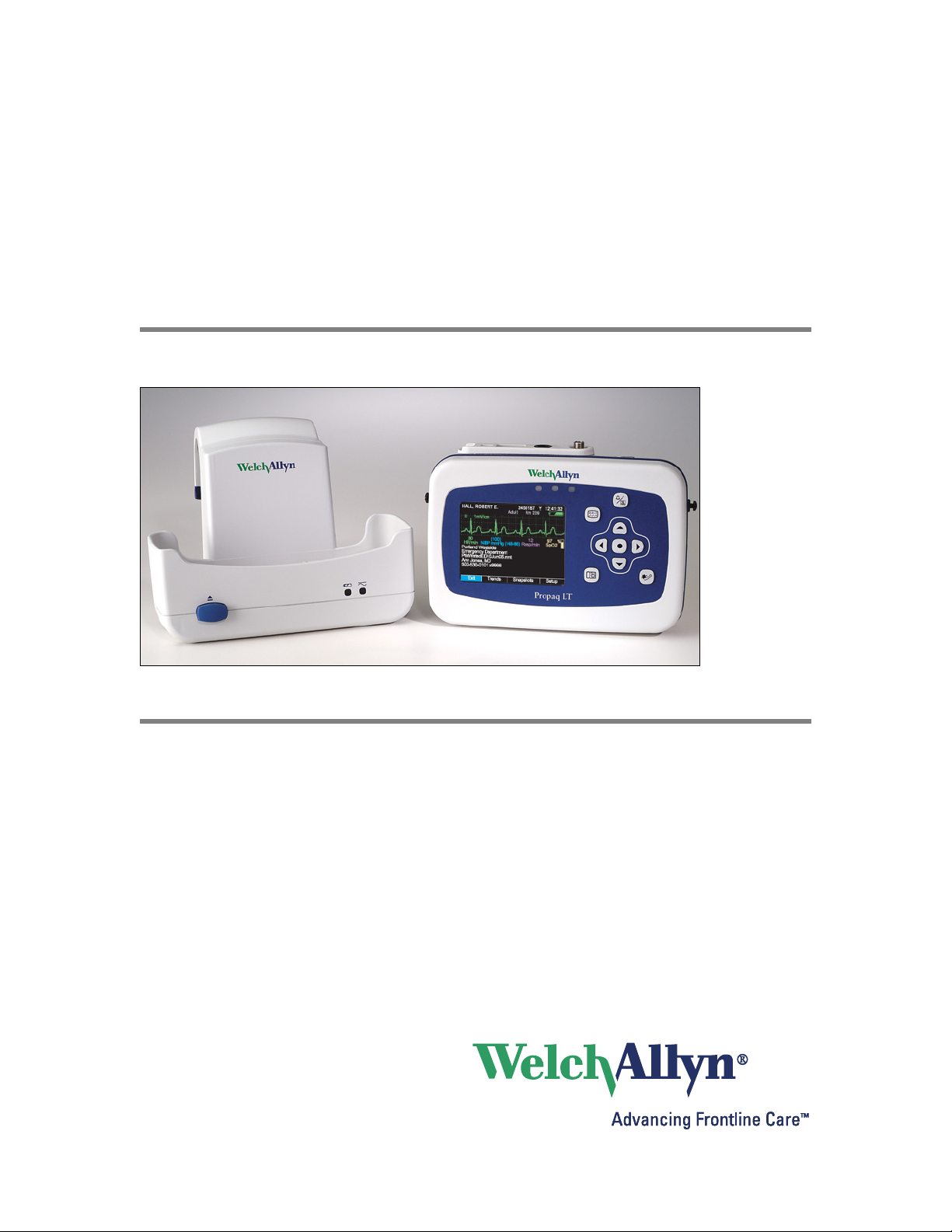
Propaq® LT
Vital Signs Monitor
Service Manual
Software version 1.3X

ii Welch Allyn Propaq LT Vital Signs Monitor
Copyright 2007 Welch Allyn. All rights are reserved. No one is permitted to reproduce or duplicate, in any
form, this manual or any part thereof without permission from Welch Allyn.
Welch Allyn assumes no responsibility for any injury to anyone, or for any illegal or improper use of the
product, that may result from failure to use this product in accordance with the instructions, cautions,
warnings, or statement of intended use published in this manual.
Welch Allyn
of Welch Allyn. ParamSet
Masimo
trademarks, of Masimo Corporation. Possession or purchase of a Masimo SpO
®
, Propaq®, Acuity®, FlexNet®, Smartcuf®, and Flexible Monitoring® are registered trademarks
®
, SET®, LNOP®, and LNCS® are registered trademarks, and FastSATtm and APODtm are
™
is a trademark of Welch Allyn.
-equipped monitor does
2
not convey any express or implied license to use the device with unauthorized sensors or cables which
would, alone or in combination with this device, fall within the scope of one or more of the patents relating
to this device.
Nellcor
®
and Oximax® are registered trademarks of Nellcor Puritan Bennett.
Software in this product is Copyright Welch Allyn or its vendors. All rights are reserved. The software is
protected by United States of America copyright laws and international treaty provisions applicable
worldwide. Under such laws, the licensee is entitled to use the copy of the software incorporated with
this instrument as intended in the operation of the product in which it is embedded. The software may not
be copied, decompiled, reverse-engineered, disassembled or otherwise reduced to human-perceivable
form. This is not a sale of the software or any copy of the software; all right, title and ownership of the
software remain with Welch Allyn or its vendors.
For information about any Welch Allyn product, call the nearest Welch Allyn representative:
USA 1800 535 6663
1315 685 4560
Canada 1800 561 8797 China 86 216 327 9631
European Call Center 353 46 906 7790 France 3315 569 5849
Germany 49 747 792 7186 Japan 8133 219 0071
Latin America 1305 669 9003 Netherlands 3115 750 5000
Singapore 656 419 8100 South Africa 2711 777 7555
United Kingdom 44 133 236 3812
Australia 6129 638 3000
800 074 793
Reorder Part Number 810-1825-XX (CD)
Reorder Part Number 810-2341-XX (Hardcopy)
Manual Part Number 810-1827-01 Rev A, 03/2007
Welch Allyn
8500 SW Creekside Place
Beaverton, Oregon 97008-7107
www.monitoring.welchallyn.com
Printed in USA

Contents
1 - Safety summary . . . . . . . . . . . . . . . . . . . . . . . . . . . . . . . . . . . . . . . . . 1
2 - Overview . . . . . . . . . . . . . . . . . . . . . . . . . . . . . . . . . . . . . . . . . . . . . . . 3
iii
Warnings. . . . . . . . . . . . . . . . . . . . . . . . . . . . . . . . . . . . . . . . . . . . . . . . . . . . . . . . 1
General safety considerations . . . . . . . . . . . . . . . . . . . . . . . . . . . . . . . . . . . . . . . 1
Electrostatic discharge (ESD) . . . . . . . . . . . . . . . . . . . . . . . . . . . . . . . . . . . . . . . . 2
Symbols . . . . . . . . . . . . . . . . . . . . . . . . . . . . . . . . . . . . . . . . . . . . . . . . . . . . . . . . 2
Purpose and scope . . . . . . . . . . . . . . . . . . . . . . . . . . . . . . . . . . . . . . . . . . . . . . . . 3
Technical support services . . . . . . . . . . . . . . . . . . . . . . . . . . . . . . . . . . . . . . . . . . 3
Returning products . . . . . . . . . . . . . . . . . . . . . . . . . . . . . . . . . . . . . . . . . . . . . . . . 4
Product configurations . . . . . . . . . . . . . . . . . . . . . . . . . . . . . . . . . . . . . . . . . . . . . 4
Recommended service intervals . . . . . . . . . . . . . . . . . . . . . . . . . . . . . . . . . . . . . 5
Service options . . . . . . . . . . . . . . . . . . . . . . . . . . . . . . . . . . . . . . . . . . . . . . . . . . . 5
Related documents. . . . . . . . . . . . . . . . . . . . . . . . . . . . . . . . . . . . . . . . . . . . . . . . 6
Controls . . . . . . . . . . . . . . . . . . . . . . . . . . . . . . . . . . . . . . . . . . . . . . . . . . . . . . . . 6
Service menu . . . . . . . . . . . . . . . . . . . . . . . . . . . . . . . . . . . . . . . . . . . . . . . . . . . . 6
3 - Troubleshooting and repair . . . . . . . . . . . . . . . . . . . . . . . . . . . . . . . . 9
Troubleshooting chart . . . . . . . . . . . . . . . . . . . . . . . . . . . . . . . . . . . . . . . . . . . . . . 9
Battery use and care. . . . . . . . . . . . . . . . . . . . . . . . . . . . . . . . . . . . . . . . . . . . . . 15
Service chart . . . . . . . . . . . . . . . . . . . . . . . . . . . . . . . . . . . . . . . . . . . . . . . . . . . . 16
Service menus for repair and network troubleshooting . . . . . . . . . . . . . . . . . . . 18
4 - Disassembly and reassembly. . . . . . . . . . . . . . . . . . . . . . . . . . . . . . 21
Procedures overview . . . . . . . . . . . . . . . . . . . . . . . . . . . . . . . . . . . . . . . . . . . . . 21
Procedures . . . . . . . . . . . . . . . . . . . . . . . . . . . . . . . . . . . . . . . . . . . . . . . . . . . . . 25
5 - Functional verification . . . . . . . . . . . . . . . . . . . . . . . . . . . . . . . . . . . 53
Functional verification overview . . . . . . . . . . . . . . . . . . . . . . . . . . . . . . . . . . . . . 53
Equipment required . . . . . . . . . . . . . . . . . . . . . . . . . . . . . . . . . . . . . . . . . . . . . . 53
Procedures . . . . . . . . . . . . . . . . . . . . . . . . . . . . . . . . . . . . . . . . . . . . . . . . . . . . . 54
Checklist and test results report form . . . . . . . . . . . . . . . . . . . . . . . . . . . . . . . . 64
6 - Replacement parts . . . . . . . . . . . . . . . . . . . . . . . . . . . . . . . . . . . . . . 67
A - 35-ml test volume . . . . . . . . . . . . . . . . . . . . . . . . . . . . . . . . . . . . . . . 69
Index . . . . . . . . . . . . . . . . . . . . . . . . . . . . . . . . . . . . . . . . . . . . . . . . . . . . 71

iv Contents Welch Allyn Propaq LT Vital Signs Monitor

1
1
Warnings
Safety summary
All users of the monitor must read this safety summary and all warning and caution
statements in the manual.
WARNING Place the monitor and accessories in locations where they cannot
harm the patient should they fall from a shelf or mount.
WARNING Do not connect more than one patient to a monitor.
WARNING Do not connect more than one monitor to a patient.
WARNING Do not use the monitor in an MRI suite or hyperbaric chamber.
WARNING To avoid explosion, do not operate the monitor in the presence of
flammable anesthetics.
WARNING Do not use cables with abraded or broken insulation.
WARNING Do not use a monitor that has been damaged. If a monitor has been
damaged, remove it from service until it has been verified for proper operation by
qualified service personnel.
Caution Do not use cables that do not operate properly.
Caution Do not autoclave the monitor.
Caution Autoclave accessories only if the manufacturer’s instructions direct you
to do so. Many accessories can be severely damaged by autoclaving.
Caution Use only accessories recommended or supplied by Welch Allyn. (See
Welch Allyn Products and Accessories, 810-0409-XX.) Always use accessories
according to the manufacturer’s instructions.
General safety considerations
• Frequently check all cables, both electrically and visually.
• If the monitor detects an unrecoverable problem, it displays a brief ‘Fault’
message. (See “Alert Messages and Status Messages”, Propaq LT Vital Signs
Monitor Directions for Use (810-1828-XX.) Report all such errors to Welch Allyn.
• Do not service a monitor under warranty. Servicing a monitor under warranty
voids the warranty. All service on monitors under warranty must be performed by
Welch Allyn or at a Welch Allyn authorized service center.
2 Safety summary Welch Allyn Propaq LT Vital Signs Monitor
Electrostatic discharge (ESD)
ATTENTION
CAUTION
SENSITIVE ELECTRONIC DEVICES
DO NOT SHIP OR STORE NEAR STRONG
ELECTROSTATIC, ELECTROMAGNETIC,
MAGNETIC OR RADIOACTIVE FIELDS.
Caution Electrostatic discharge (ESD) can damage or destroy electronic
components. Handle static-sensitive components only at static-safe workstation.
Caution Assume that all electrical and electronic components of the monitor
are static-sensitive.
Electrostatic discharge is a sudden current flowing from a charged object to another
object or to ground. Electrostatic charges can accumulate on common items such as
foam drinking cups, cellophane tape, synthetic clothing, untreated foam packaging
material, and untreated plastic bags and work folders, to name only a few.
Electronic components and assemblies, if not properly protected against ESD, can be
permanently damaged or destroyed when near or in contact with electrostatically charged
objects. When you handle components or assemblies that are not in protective bags and
you are not sure whether they are static-sensitive, assume that they are static-sensitive
and handle them accordingly.
OBSERVE PRECAUTIONS
FOR HANDLING
ELECTROSTATIC
SENSITIVE DEVICES
Symbols
• Perform all service procedures in a static-protected environment. Always use
techniques and equipment designed to protect personnel and equipment from
electrostatic discharge.
• Remove static-sensitive components and assemblies from their static-shielding
bags only at static-safe workstations—a properly grounded table and grounded
floor mat—and only when you are wearing a grounded wrist strap (with a resistor
of at least 1 megohm in series) or other grounding device.
• Use only grounded tools when inserting, adjusting, or removing static-sensitive
components and assemblies.
• Remove or insert static-sensitive components and assemblies only with monitor
power turned off.
• Insert and seal static-sensitive components and assemblies into their original
static-shielding bags before removing them from static-protected areas.
• Always test your ground strap, bench mat, conductive work surface, and ground
cord before removing components and assemblies from their protective bags and
before beginning any disassembly or assembly procedures.
WARNING Indicates conditions that could lead to illness, injury, or death.
Caution In this manual, indicates conditions that could damage equipment or other property.

3
2
Overview
Purpose and scope
This is a reference for periodic preventive maintenance and corrective service procedures
for the Propaq LT monitor, Models 802LT0N, 802LTRN, 802LT0S, and 802LTRS.
Corrective service is supported to the level of field-replaceable units. Field-replaceable
units include certain circuit-board assemblies, subassemblies, case parts, and other parts.
All field-replaceable parts are listed in “Replacement parts” on page 67.
WARNING When performing a service procedure, follow the instructions
exactly as presented in this manual. Failure to do so could damage the monitor,
invalidate the product warranty, and lead to serious personal injury.
Caution No component-level repair of circuit boards and subassemblies is
supported. Use only the repair procedures described in this manual.
Note
Repair and replacement of the main board is not supported. Any service work on
the main board must be performed by certified and qualified service personnel at
an authorized Welch Allyn service center. (For contact information, see page ii.)
Repair and replacement of the radio and the antenna is not supported. Any
service work on the radio and the antenna must be performed by certified and
qualified service personnel at an authorized Welch Allyn service center. (For
contact information, see page ii.)
This guide provides troubleshooting information, assembly procedures, and instructions
for functional testing and performance verification. It is intended for use only by
technically qualified service personnel.
This guide applies only to the Propaq LT monitor. For service information about any other
model of the Propaq monitor, refer to the service manual for that product.
Technical support services
Welch Allyn offers the following technical support services:
Telephone support (1-800-289-2501 and 1-503-530-7500)
Loaner equipment
Service agreements
Service training
Replacement service parts
Factory service
For information on any of these services, call one of the numbers listed on page ii.

4 Overview Welch Allyn Propaq LT Vital Signs Monitor
Returning products
To return a product for service, contact Welch Allyn Technical Support and request a
Return Material Authorization (RMA) number.
Note
Welch Allyn does not accept returned products without an RMA.
When requesting an RMA, please have the following information available:
• Product name, model number, and serial number.
• Your customer number.
• A contact name and phone number.
• A complete return shipping address.
• Any special shipping instructions.
• A purchase-order number or credit-card number if the product is not covered by
warranty.
• A full description of the problem or service request.
Note
To ensure safe receipt of your monitor by the service center and to expedite
processing and return of the monitor to you, thoroughly clean all residues from
the monitor before you ship it to Welch Allyn.
United States federal regulations prohibit the processing of any device
contaminated with blood-borne pathogens. Welch Allyn thoroughly cleans all
returned monitors on receipt, but any monitor that cannot be adequately cleaned
cannot be repaired.
Before shipping the monitor, please observe these packing guidelines:
• Remove from the package all hoses, connectors, cables, sensors, power cords,
and other ancillary products and equipment, except those items that might be
associated with the problem.
• Put the monitor, enclosed in a plastic bag with a packing list, into the original
shipping carton with the original packing materials or into another appropriate
shipping carton.
• Write the Welch Allyn RMA number with the Welch Allyn address on the outside
of the shipping carton.
Product configurations
Model numbers for the configurations are as follows:
Model Monitoring Parameters FlexNet/Acuity
802LT0N ECG, NIBP, Nellcor SpO
802LTRN ECG, NIBP, Nellcor SpO
802LT0S ECG, NIBP, Masimo SpO
802LTRS ECG, NIBP, Masimo SpO
Communication Enabled
2
2
2
2
No 007-0160-XX KA
Yes 007-0161-XX KA
No 007-0268-XX KA
Yes 007-0269-XX KA
Top-Level
Assembly
Serial #
Prefix

Service Manual Overview 5
Recommended service intervals
Interval or condition Action recommended Procedure
Every 6 - 24 months
(per hospital protocols)
Every 36 months Replace the air filter “Replacing the air filter” on page 26
Every 36 months Replace the battery “Removing the lithium ion battery
The battery does not hold a charge Check battery capacity
The monitor has been dropped or
otherwise damaged
The monitor is not functioning
properly
The monitor does not pass the
functional verification
Verify functionality “Functional verification” on page 53
assembly” on page 25
“Functional verification” on page 53
Replace the battery
Verify functionality “Functional verification” on page 53
Verify functionality “Functional verification” on page 53
Troubleshoot and repair, and then
verify functionality
“Removing the lithium ion battery
assembly” on page 25
“Troubleshooting and repair” on page 9
“Disassembly and reassembly” on page 21
“Functional verification” on page 53
Service options
Warranty service
All repairs on products under warranty must be performed or approved by Welch Allyn.
Refer all warranty service to Welch Allyn Factory Service or another authorized Welch
Allyn Service Center. Obtain an RMA number for all returns to Welch Allyn Factory
Service. (See “Returning products” on page 4.)
Caution Unauthorized repairs will void the product warranty.
Non-warranty service
Welch Allyn Beaverton Factory Service and authorized Service Centers support nonwarranty repairs. Contact any Welch Allyn regional service center for pricing and service
options.
Welch Allyn offers modular repair parts for sale to support non-warranty service. This
service must be performed only by qualified end-user biomedical/clinical engineers using
this service manual.
Return the monitor to an authorized
Welch Allyn service center
“Returning products” on page 4
6 Overview Welch Allyn Propaq LT Vital Signs Monitor
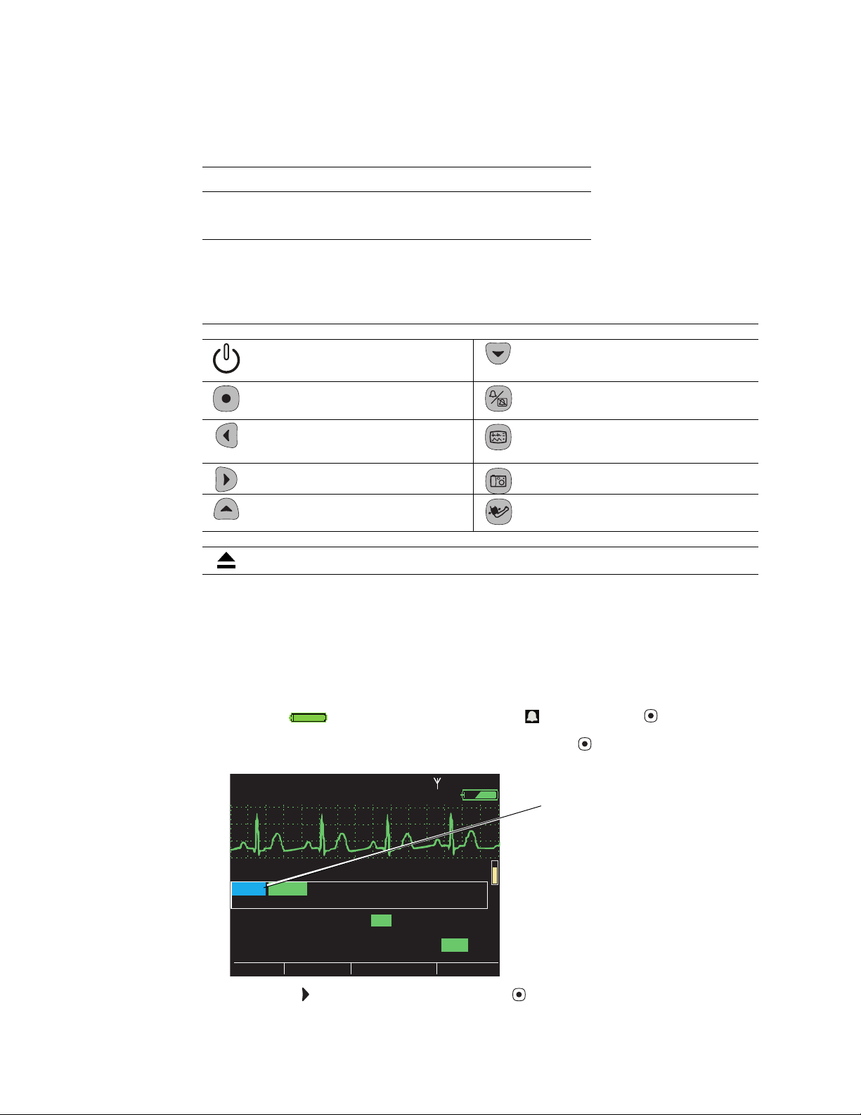
II 1mV/cm
Exit
Trends
Snapshots
Setup
Low
Med
80
HR/min
140/78
NIBP mmHg (102)
Resp/min
SpO2
OffOnOn
Alarm Tone
Suspend Audible Alarms:
Setup:
(90 sec)
12
97
%
HALL, ROBERT E.
3456187
3:00:06P
Adult,
Rm 239
Alarms
ECG
NIBP
Timings
High
Service
Configuration
Related documents
Title Reorder Number
Propaq LT Vital Signs Monitor Directions for Use 810-1828-XX
Welch Allyn Products and Accessories 810-0409-XX
Controls
Monitor
Power - Turn the monitor power on or off. Down - Move the cursor down to the next display
item.
Service menu
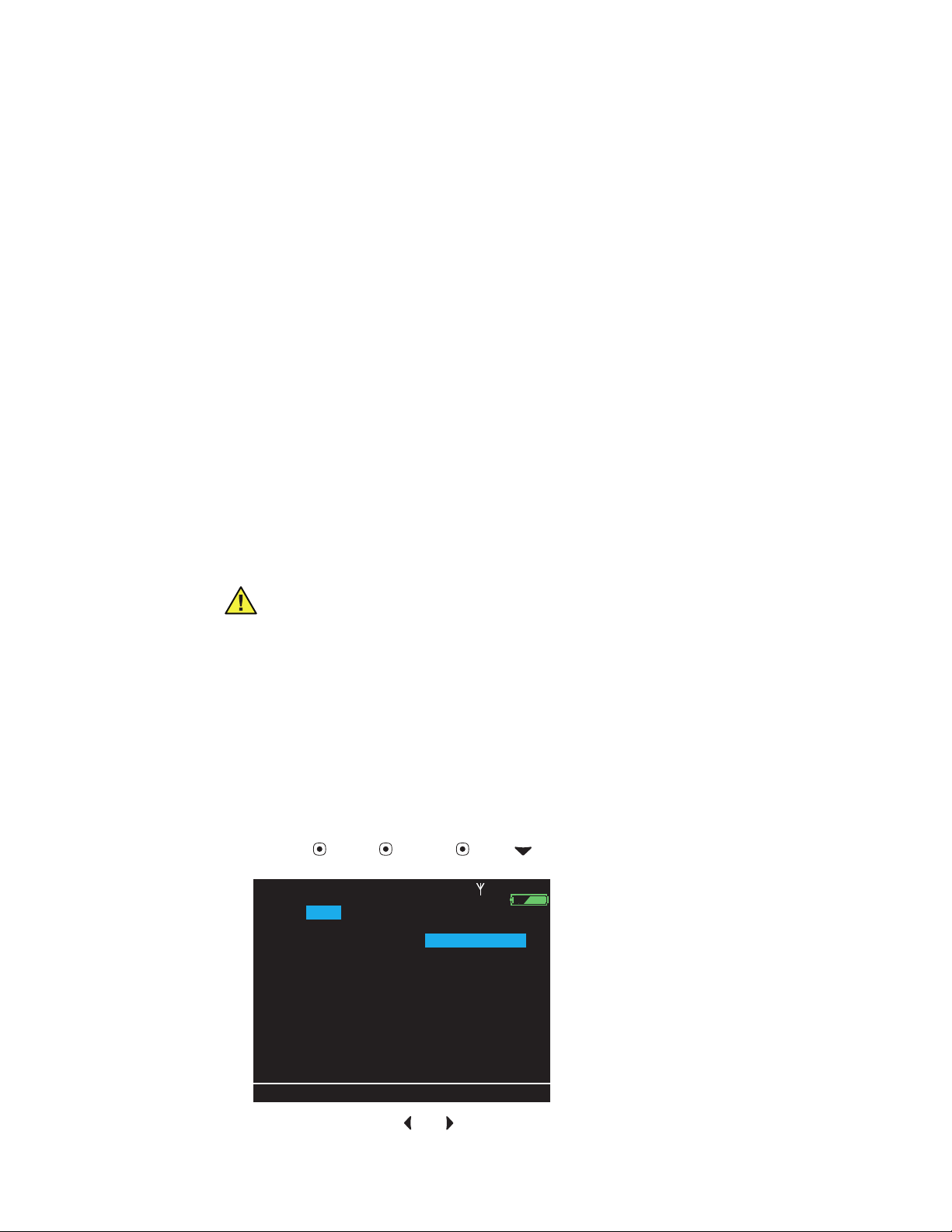
To access the monitor service menu:
From any main display screen (such as Large Numerics, Dual Waveform, ...):
1. Highlight , HR/PR, SpO2, NIBP, Resp, or , and then press .
2. Highlight Setup (at the bottom of the screen) and press . The setup menu appears.
HALL, ROBERT E.
II 1mV/cm
Action - Act based on what is highlighted. Silence/Reset - Silence the current alarm tone
for 90 seconds or reset a silenced alarm tone.
Left - Move the
cursor left to the next display
item; decrease the parameter value.
Display - Cycle to the next configured display
format, or cancel the current control, setup, or
pop-up menu.
Right - Move the cursor right to the next
display item; increase the parameter value.
Up - Move the cursor up to the next display
item.
Snapshot - Record a 21
-second period of numeric
and waveform data.
Start/Stop NIBP - Start or stop an NIBP
measurement.
Cradle
Monitor Release - Press and hold while removing the monitor from the cradle.
Adult,
3456187
Rm 239
3:00:06P
Setup Menu
80
HR/min
Setup:
Suspend Audible Alarms:
Alarm T one
Exit
3. Scroll right ( ) to highlight Service, and press . The service menu appears, with
NIBP and Show Info highlighted.
NIBP mmHg (102)
Alarms
Service
Trends
140/78
ECG
NIBP
12
Resp/min
Timings
Off
Low
Med
Snapshots
97
SpO2
Configuration
(90 sec)
High
Setup
%
Service Manual Overview 7
II 1mV/cm
Exit
Trends
Snapshots
Setup
HR/min
NIBP mmHg
Resp/min
SpO2
Timings
Service
Alarms
ECG
NIBP
Setup
%
STEWART, ANN
7762940
3:00:06P
Adult
Rm ICU 263
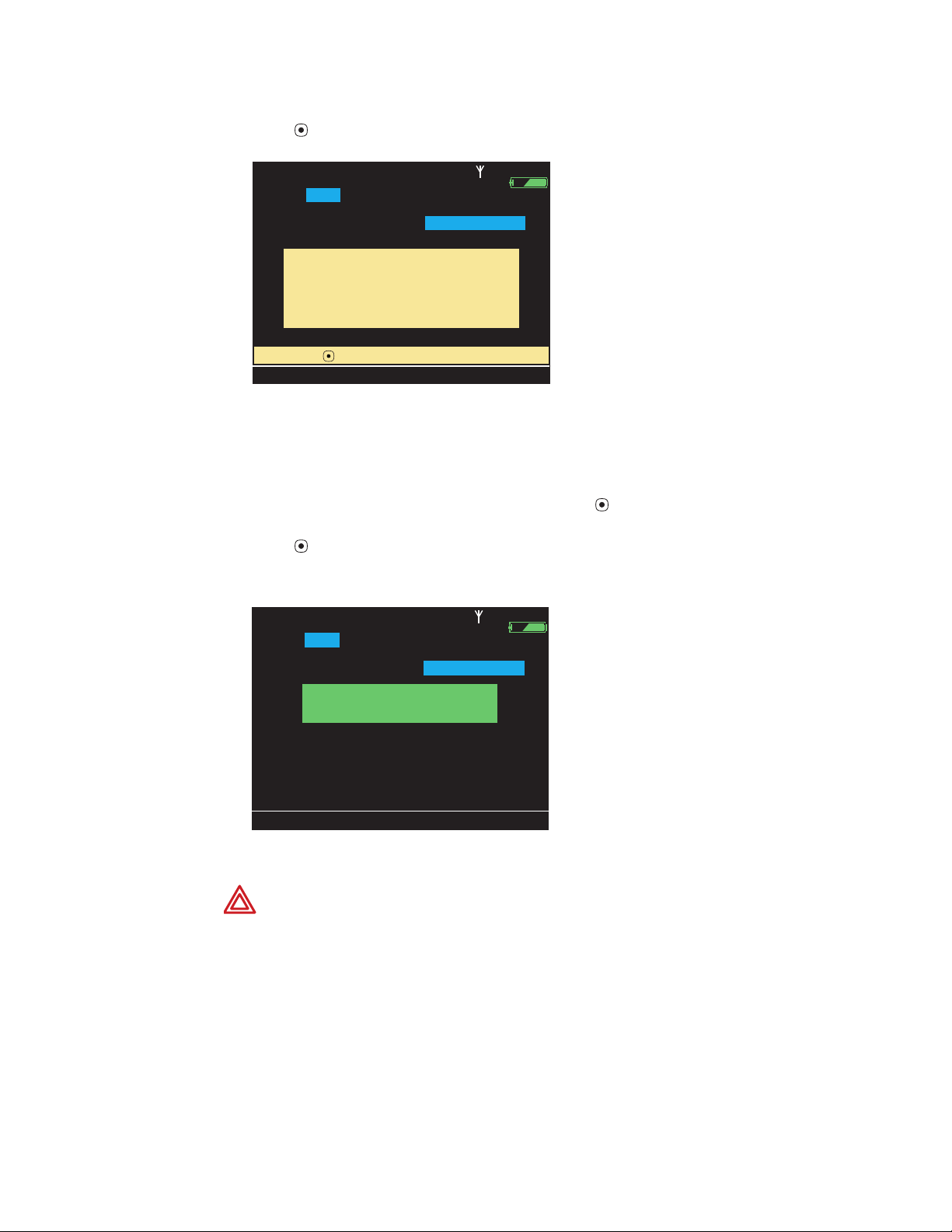
(qualified service personnel only).
Select ( ) to enter service menus
Configuration
Exit
NIBP
STEWART, ANN
7762940
3:00:06P
Adult
Rm ICU 263
Service
ECG
SpO2
USB
Radio
Software
Display
Battery
Voltages
Buttons
NIBP
Show Info
NIBP Test
Characterize Pump
STEWART, ANN
II 1mV/cm
HR/min
Alarms
Setup
Service
Select ( ) to enter service menus
(qualified service personnel only).
Exit
Trends
STEWART, ANN
NIBP
Service
Display
NIBP
Show Info
NIBP mmHg
ECG
NIBP
ECG
SpO2
Battery
NIBP Test
7762940
Adult
Rm ICU 263
Resp/min
Timings
Snapshots
7762940
Adult
Rm ICU 263
USB
Voltages
Characterize Pump
3:00:06P
SpO2
Configuration
Setup
3:00:06P
Radio
Software
Buttons
%
Service
Exit
The service menu contains 10 sections:
Section Operations Status displays
NIBP Test NIBP, Characterize Pump Show Info
ECG Setup (Enable/Disable HR/PR Alarms) Parameters
SpO
2
USB (none) Show Info
Radio Monitoring (Monitor the radio), Set Netname Show Info, View and Set Netname
Software (none) View Error Log, View RAM Dump, View System Info
Display Run Pixel Test, Set Bias View Fonts
Battery (none) Show Info
Voltages (none) Show Info
Buttons Test Buttons (none)
(none) Show Info

8 Overview Welch Allyn Propaq LT Vital Signs Monitor

9
3
Troubleshooting and repair
Troubleshooting chart . . . . . . . . . . . . . . . . . . . . . . . . . . . . . . . . . . . . . . . . . . . . . .9
Battery use and care . . . . . . . . . . . . . . . . . . . . . . . . . . . . . . . . . . . . . . . . . . . . . . 15
Service chart . . . . . . . . . . . . . . . . . . . . . . . . . . . . . . . . . . . . . . . . . . . . . . . . . . . .16
Service menus for repair and network troubleshooting . . . . . . . . . . . . . . . . . . . 18
Troubleshooting chart
Caution Replace parts, components, or accessories only with parts supplied or
approved by Welch Allyn. The use of any other parts can lead to inferior monitor
performance and will void the product warranty.
General
Refer to "Service chart" on page 16 for information on the suggested corrective actions.
Symptom Possible cause Possible corrective action
The power-on self-test fails.
(Indicator: 2 yellow LED flashes
followed by an LED flash of any
combination of green, yellow, and
red).
Internal RAM failure. Cycle the power. If the error persists, send the
Software error.
Unexpected reset detected.
monitor to an authorized Welch Allyn Service
Center for service. (See "Returning products"
on page 4.)
“Recoverable Fault.
Restart monitor.“
“System Fault.
Service monitor.“
“System Fault.
Service radio.“
“Battery Fault.
Install new battery.“
“Equipment Alert.
Charger Fault.
Service Charger.“
An invalid condition has been
detected that might be resolved
by restarting the monitor.
An unrecoverable system error
has occurred.
Radio fault detected. Send the monitor to an authorized Welch Allyn
The battery is not performing to
specification.
Charging has timed out (Charger
state 5).
Cradle power board failure. Insert another monitor and battery pack in the
Restart the monitor. If the fault does not
reappear, continue to use the monitor.
Send the monitor to an authorized Welch Allyn
Service Center for service. (See "Returning
products" on page 4.)
Service Center for service. (See "Returning
products" on page 4.)
Install a new battery. "Removing the lithium
ion battery assembly" on page 25.
Remove the monitor from the cradle and
reinsert it, and then attempt again to charge
the battery. If the timeout reoccurs, replace the
battery. "Removing the lithium ion battery
assembly" on page 25.
cradle and verify that the symptoms persist. If
yes, then replace the cradle power board.
"Disassembling the cradle" on page 44.

10 Troubleshooting and repair Welch Allyn Propaq LT Vital Signs Monitor
Symptom Possible cause Possible corrective action
Monitor fails to power up beyond the
initial screen.
Button board not connected. Connect the button board to the main board.
"Separating the top and bottom chassis
halves" on page 27.
Monitor is in the cradle and does not
power up, and the cradle power
indicator is off.
Monitor is latched in the cradle but
does not power up. Power indicator
on the cradle is on.
Monitor battery fails to charge.
DC power is applied but the power
indicator on the cradle remains off.
Monitor battery run time duration is
less than specified.
Yellow indicator on the cradle. Monitor current draw is too
The battery is discharged and
the cradle is not powering the
monitor.
Defective power adapter. Replace the power adapter.
The charger input fuse is blown. Replace the fuse. "Replacing the fuse" on
Open the monitor power switch. Replace the bottom chassis (which includes
Problem with the cradle power
board.
Problem with the monitor. Send the monitor to an authorized Welch Allyn
Blown power input fuse on the
charger I/O panel.
The battery is deficient. Replace the battery. "Removing the lithium ion
Radio cannot link up to the
Acuity Central Station.
high.
Cradle circuit breaker is tripped.
Charger state 1.
Verify that AC power is on, that the power
adapter is plugged into AC power and into the
cradle, and that the monitor is fully seated in
the cradle.
page 44.
the power switch). "Removing the main board
from the bottom chassis assembly" on
page 32.
Replace the cradle power board.
"Disassembling the cradle" on page 44.
Service Center for service. (See "Returning
products" on page 4.)
Replace the fuse. "Replacing the fuse" on
page 44.
battery assembly" on page 25.
See "Radio" on page 12.
Service the monitor or the cradle.
Monitor has no battery pack.
Charger state 4.
Battery pack temperature is out
of range. Charger state 3.
Battery pack voltage is too low
or the battery fuse is blown.
Charger state 4.
Battery pack fails to charge in
the specified time. Charger
state 5.
Battery cell(s) over voltage;
probably a charge imbalance.
Charger state 7.
Charger board failure. Examine the cradle internal cabling, the cradle
Missing or erroneous LCD characters Faulty LCD. Replace the LCD. "Disassembling the top
Install the monitor battery pack. "Removing the
lithium ion battery assembly" on page 25.
Return the battery pack to within the specified
temperature range (0
Replace the battery pack. "Removing the
lithium ion battery assembly" on page 25.
Remove the monitor from the cradle and
reinsert it, and then attempt again to charge. If
the timeout reoccurs, replace the battery pack.
"Removing the lithium ion battery assembly"
on page 25.
Replace the battery pack. "Removing the
lithium ion battery assembly" on page 25.
power board, and the interconnect board.
"Removing the power/USB flex connector from
the bottom chassis" on page 43.
chassis" on page 30.
°C - 40°C).

Service Manual Troubleshooting and repair 11
Symptom Possible cause Possible corrective action
Button or buttons inoperative. Faulty button or buttons. Replace the top chassis assembly.
"Disassembling the top chassis" on page 30.
Voltages displayed on the service
menu are out of range.
Repeated occurrence of “SpO
No sensor detected.“
2
Fault.
The NIBP air leak exceeds the
specification.
“Equipment Alert.
NIBP Fault.
Air leak. Check hose.“
Repeated occurrence of “NIBP Fault.
Air leak. Check hose.“
“Equipment Alert.
NIBP Fault.
Kinked or neonate hose.“
“Equipment Alert.
NIBP Fault.
Overpressure condition.“
Main board fault. Send the monitor to an authorized Welch Allyn
Service Center for service. (See page ii.)
The internal SpO2 connector is
loose.
Secure the internal SpO2 connector.
"Removing the main board from the bottom
chassis assembly" on page 32.
Faulty SpO
connector panel. Replace the connector panel. "Removing the
2
patient connector panel from the bottom
chassis" on page 42.
Worn O-ring in the NIBP hose
Try a different NIBP hose or replace the O-ring.
connector.
Deficient NIBP check valve,
bleed valve, or overpressure
Replace the valve. "Removing the NIBP
assembly from the main board" on page 38.
valve.
NIBP tubing not properly
connected.
Connect the internal tubing. "Removing the
NIBP assembly from the main board" on
page 38.
If hoses and external fittings are
not leaking, internal tubing
might be disconnected.
Connect the internal tubing. "Removing the
NIBP assembly from the main board" on
page 38.
Internal tubing is disconnected. Connect the internal tubing. "Removing the
NIBP assembly from the main board" on
page 38.
Internal tubing is damaged. Replace the damaged section of internal
tubing. "Removing the NIBP assembly from the
main board" on page 38.
If the correct hose is connected
and not kinked, then the internal
tubing might be blocked.
Verfify that the internal in-line NIBP pneumatic
components are properly installed, with no
pinching or kinking of tubing. "Removing the
NIBP assembly from the main board" on
page 38.
A transient pressure pulse was
Restart the monitor.
introduced into the cuff via
sudden and excessive patient
motion.
“Equipment Alert.
NIBP Fault.
Calibrating. Please wait.“
“Calibrating.
Minimize motion.“
“Equipment Alert.
NIBP Fault.
Service required. NIBP disabled.“
The NIBP system self-test has failed
3 times without passing.
An NIBP measurement was
attempted within 45 seconds of
Wait 45 seconds after turning on the monitor
before starting an NIBP measurement.
monitor power-up.
An NIBP measurement was
attempted while the NIBP
Wait 15 seconds and retry the NIBP
measurement.
system was performing a
baseline calibration.
Excessive cuff artifact. Reduce patient motion.
Excessive artifact. Minimize patient motion.
NIBP subsystem failure. Send the monitor to an authorized Welch Allyn
Service Center for service. (See "Returning
products" on page 4.)

12 Troubleshooting and repair Welch Allyn Propaq LT Vital Signs Monitor
Radio
This radio troubleshooting guide applies to issues specific to the Propaq Model 802 LTRN
and 802 LTRS monitors and is not intended for comprehensive troubleshooting of the
Acuity system. To troubleshoot the Acuity system, refer to the appropriate Acuity service
contact for your system.
Symptom Possible Cause Possible Corrective Action
No Acuity connection—network
communication icon ( ) is not
displayed on the monitor screen.
No Acuity connection—network
communication icon with slash ( )
is displayed on the monitor screen
and the yellow indicator above
the screen is lit.
No Acuity connection—network
communication icon with slash ( )
and “Disconnected” are displayed
on the monitor screen, and the
green indicator above the screen
is flashing.
Wireless communication disabled
in the monitor configuration.
Monitor is out of radio range.
(RSSI > approx. 60.)
Netname (ESSID) set wrong. Set the monitor network name to the Acuity
USB connected to the monitor
through the cradle.
Monitor is intentionally
disconnected from the network by
the user.
Use the configuration utility to enable wireless
communication for the monitor.
Move the monitor within range of an Acuity
access point. (RSSI < approx. 60.)
network name. (Default: com.protocol.)
Disconnect the USB cable from the cradle.
Use the monitor interface to connect to the
network.
Radio Monitoring service screen
persistently displays “Searching
for access point.”
Radio Monitoring service screen
persistently displays “Requesting
an IP address.”
Radio Monitoring service screen
persistently displays “Contacting
Acuity.”
Frequent communication faults
with no apparent cause. On the
Radio Monitoring service screen,
TX Retries and RX CRC errors
(PERCENT) is > 5%.
Monitor radio cannot find a signal
from the network.
DHCP server is down. Contact Welch Allyn Acuity technical support.
DHCP server has no more
addresses.
All Acuity systems with wireless
are unavailable.
The Acuity system is at capacity
for licenses.
Faulty antenna or poor antenna
connection.
Faulty radio connection. Send the monitor to an authorized Welch Allyn
Poor radio coverage. Verify that the network has a sufficient density
Move the monitor within range of a network
access point.
Verify the Netname.
(See page ii.)
Contact Welch Allyn Acuity technical support.
(See page ii.)
Wait.
Turn off another wireless monitor.
Send the monitor to an authorized Welch Allyn
Service Center for service. (See "Returning
products" on page 4.)
Service Center for service. (See "Returning
products" on page 4.)
of access points.

Service Manual Troubleshooting and repair 13
Battery states and service
State Description Type of State Possible Corrective Action
0 Battery state unknown. Normal transitory. Should not
persist.
1 Battery voltage too high.
(Indication can occur with the
monitor in or out of the cradle.)
2 Battery fully charged. Normal operating state.
3 Battery partially charged. Normal operating state.
4 30 minutes of charge
remaining, undocked.
5 30 minutes of charge
remaining, docked.
6 5 minutes of charge
remaining, undocked.
7 5 minutes of charge
remaining, docked.
8 Battery is exhausted,
undocked.
9 Battery is exhausted, docked. Normal operating state.
10 Battery voltage is too low for
recharging, docked.
Fault—possible cell imbalance
or charger fault
Normal operating state.
Normal transitory state.
Normal operating state.
Normal transitory state.
Normal operating state.
Faulty battery pack. Replace the battery pack. "Removing the
If the state persists, replace the battery
pack. "Removing the lithium ion battery
assembly" on page 25.
Replace the battery pack ("Removing the
lithium ion battery assembly" on page 25)
or the cradle power board ("Disassembling
the cradle" on page 44).
lithium ion battery assembly" on page 25.

14 Troubleshooting and repair Welch Allyn Propaq LT Vital Signs Monitor
Charger states and service
State Description Charger
Status
LED
0 Charger state
unknown.
1 Monitor docked,
No-power fault.
2 Monitor docked,
charging.
3 Monitor docked,
temperature
fault.
n/a n/a Normal initial transitory state of
Off Off Normal operating state when the
Yellow On Fault—power to the monitor
Green Green Normal operating state. n/a
Yellow Green Fault—battery pack temperature
Charger
Power
LED
Type of State Possible Corrective Action
n/a
very short duration.
If the power adapter is not
monitor is in the cradle and the
cradle is not powered.
Fault state if the cradle fuse is
open.
automatically disconnected by the
cradle. Possible monitor fault.
Fault—no monitor in the cradle,
power input and input fuse OK.
is out of range high or low.
connected, connect it.
Replace the fuse. "Replacing the
fuse" on page 44.
Attempt to recharge by removing
the monitor from the cradle and
reinserting the monitor in the
cradle.
If the fault persists, attempt to
recharge another monitor to
determine whether the problem is
with the cradle or with the
monitor main board.
Power board fault. Replace the
power board. "Disassembling the
cradle" on page 44.
Bring the battery pack
temperature into specified range
(0° C - 40° C).
4 Monitor docked,
battery voltage
too low for
charging.
5 Monitor docked,
timeout fault.
6 Monitor docked,
charging
complete.
7 Monitor docked,
overcharge
fault.
8 Monitor not
docked.
Yellow Green Fault—battery pack can no longer
be charged.
Yellow Green Fault—Battery pack failed to
charge within the specified time.
Off Green Normal operating state. n/a
Yellow Green Fault—battery pack cells are
unbalanced or the cradle is faulty.
n/a n/a Normal operating state. n/a
Replace the battery pack.
"Removing the lithium ion battery
assembly" on page 25.
Attempt again to charge by
removing the monitor from the
cradle and reinserting the monitor
in the cradle.
Replace the battery pack.
"Removing the lithium ion battery
assembly" on page 25.
Replace the battery pack
("Removing the lithium ion battery
assembly" on page 25).
Replace the power board in the
cradle ("Disassembling the
cradle" on page 44).

Service Manual Troubleshooting and repair 15
Battery use and care
The battery meets specification when used in an environment between 0° C and 40° C.
• Operating the monitor in a cold environment (below 20° C) reduces battery run time.
When the battery is returned to a warmer environment, battery run time returns to
normal.
• Sustained charging at high temperatures (near 40° C) reduces battery life.
• The battery continues to discharge when removed from the monitor, but at a much
slower rate than if it were in the monitor.
• The battery, when removed from the monitor, discharges more slowly at low
temperatures and more quickly at high temperatures.
• Maintain battery capacity by storing the battery:
✓ in a discharged state
✓ removed from the monitor
✓ in a cool, dry place

16 Troubleshooting and repair Welch Allyn Propaq LT Vital Signs Monitor
Service chart
This chart shows which procedure to use for specific service operations on monitors not
covered by warranty.
Caution Do not service a monitor under warranty. Any service not performed at
a Welch Allyn service center voids the product warranty.
Monitor
Note
Do not attempt to replace any component, including the NIBP pressure
transducers, soldered onto the main board. All service of the main board must be
performed at the Welch Allyn factory service center.
Service Action
Replace the NIBP air filter. "Replacing the air filter" on page 26.
Replace the battery pack. "Removing the lithium ion battery assembly" on
page 25.
Replace the connector panel 1. "Removing the patient connector panel from
the bottom chassis" on page 42.
2. "Functional verification" on page 53.
Replace the LCD assembly 1. "Disassembling the top chassis" on page 30.
Replace the top case assembly (with button board and window) 1. "Disassembling the top chassis" on page 30.
Replace the bottom case assy (with power switch, power flex
cable, and connector panel)
Replace the NIBP pump, bleed and dump valves, check valve, or
internal tubing
Update the software Send the monitor to a Welch Allyn service center.
Replace the main board Send the monitor to a Welch Allyn service center.
2. "Set LCD bias" on page 20
3. "Functional verification" on page 53.
2. "Functional verification" on page 53.
1. "Removing the main board from the bottom
chassis assembly" on page 32.
2. "Functional verification" on page 53.
1. "Removing the NIBP assembly from the main
board" on page 38.
2. "Characterize NIBP" on page 18.
3. "Functional verification" on page 53.
(See "Returning products" on page 4.)
(See "Returning products" on page 4.)

Service Manual Troubleshooting and repair 17
Cradle
Service Action
Replace the fuse 1. "Replacing the fuse" on page 44.
Replace the interconnect board 1. "Disassembling the cradle" on page 44.
Replace the power board 1. "Disassembling the cradle" on page 44
Replace the I/O panel 1. "Disassembling the cradle" on page 44
Replace the upper housing 1. "Disassembling the cradle" on page 44
Replace the lower housing 1. "Disassembling the cradle" on page 44
2. "Functional verification" on page 53.
2. "Functional verification" on page 53.
2. "Functional verification" on page 53.
2. "Functional verification" on page 53.
2. "Functional verification" on page 53.
18 Troubleshooting and repair Welch Allyn Propaq LT Vital Signs Monitor
internal NIBP components.
See the Propaq LT Service Manual
for the NIBP Characterization Procedure.
Show Info
NIBP:
Pump Test
HALL, ROBERT E.
3456187
12:41:32P
Adult,
Rm 239
Audible Alarms Silenced
Service:
NIBP
ECG
SpO2
USB
Radio
Software
Display
Battery
Voltages
Buttons
Characterize NIBP
Characterize NIBP after service to any
Exit
Service menus for repair and network troubleshooting
In addition to the service menus supporting functional verification, these menus support
the following service procedures:
Characterize NIBP . . . . . . . . . . . . . . . . . . . . . . . . . . . . . . . . . . . . . . . . . . . . . 18
Set LCD bias . . . . . . . . . . . . . . . . . . . . . . . . . . . . . . . . . . . . . . . . . . . . . . . . .20
Check radio status. . . . . . . . . . . . . . . . . . . . . . . . . . . . . . . . . . . . . . . . . . . . .20
Note
Before beginning any service procedure, read the entire procedure to verify that
you have all tools and equipment needed and that you understand each step.
Characterize NIBP
NIBP characterization sets the volume constants for the NIBP system to assure proper
cuff detection. You must characterize the NIBP system if any of the following occurs:
• Characterization test failure
• Pump failure
• Internal tubing replacement (any or all)
• Bleed valve, dump valve, or check valve replacement
• Main board replacement or repair
Caution Main board repair must be performed at the Welch Allyn Factory
Service Center. Any change to the main board requires system testing,
calibration, and verification, which can be done only at the Factory Service
Center.
Caution Perform this characterization procedure only if you are prepared and
equipped to perform the "Characterization test" on page 59. To complete this
test, you must have the 35-ml test syringe described in "35-ml test volume" on
page 69.
1. Attach a neonatal hose (008-0265-XX) to the monitor NIBP hose connector. Verify that
2. On the monitor, navigate to the Characterize NIBP screen.
3. Simultaneously press and to access the NIBP characterization service screens. A
the hose length is 8 feet ± 4 inches (2.44 meters ± 10 cm).
HR/min Setup Service NIBP Characterize NIBP.
HALL, ROBERT E.
Audible Alarms Silenced
Service:
NIBP:
NIBP
ECG
Display
Show Info
Characterize NIBP after service to any
for the NIBP Characterization Procedure.
Battery
Pump Test
internal NIBP components.
See the Propaq LT Service Manual
Adult,
SpO2
Exit
3456187
USB
Voltages
Radio
Buttons
12:41:32P
Software
Rm 239
Characterize NIBP
warning message appears: “NIBP characterization affects neonatal cuff detection.”
Service Manual Troubleshooting and repair 19
without cuff to the Propaq LT.
2. Block the open end of the hose.
3. With the hose completely blocked,
Show Info
NIBP:
Pump Test
HALL, ROBERT E.
3456187
12:41:32P
Adult,
Rm 239
Audible Alarms Suspended
Service:
NIBP
ECG
SpO2
USB
Radio
Software
Display
Battery
Voltages
Buttons
Characterize NIBP
1. Connect a standard neonatal NIBP hose
Exit
Select ( ) to initialize NIBP characterization.
press the select button.
PROPER NEONATAL CUFF DETECTION.
Failure to perform the verification can result in
overinflation of neonatal cuffs.
Show Info
NIBP:
Pump Test
HALL, ROBERT E.
3456187
12:41:32P
Adult,
Rm 239
Audible Alarms Suspended
Service:
NIBP
ECG
SpO2
USB
Radio
Software
Display
Battery
Voltages
Buttons
Characterize NIBP
THE VERIFICATION TEST ASSURES
Exit
NIBP Characterized.
Perform verification procedure now.
4. Press to continue. The first steps of the procedure appear:
HALL, ROBERT E.
Audible Alarms Suspended
Service:
NIBP:
NIBP
ECG
Display
Show Info
1. Connect a standard neonatal NIBP hose
2. Block the open end of the hose.
3. With the hose completely blocked,
Select ( ) to initialize NIBP characterization.
Battery
Pump Test
without cuff to the Propaq LT.
press the select button.
Adult,
SpO2
Exit
3456187
USB
Voltages
Radio
Buttons
12:41:32P
Software
Rm 239
Characterize NIBP
5. Follow the steps as presented on the screen.
Note
The standard neonatal NIBP hose (008-0265-xx) can be effectively blocked with
firm thumb pressure over the fitting opening.
Note
In this procedure, ‘the select button’ refers to .
6. Press to begin characterization.
When the characterization is complete, this screen appears:
HALL, ROBERT E.
Audible Alarms Suspended
Service:
NIBP:
NIBP
Display
Show Info
ECG
Battery
Pump Test
Adult,
SpO2
3456187
USB
Voltages
Radio
Buttons
12:41:32P
Software
Rm 239
Characterize NIBP
NIBP Characterized.
Perform verification procedure now.
THE VERIFICATION TEST ASSURES
PROPER NEONATAL CUFF DETECTION.
Failure to perform the verification can result in
overinflation of neonatal cuffs.
Exit
7. Verify the characterization. ("Characterization test" on page 59.)
WARNING Always verify after characterization. Failure to verify a new
characterization could result in overinflation of a neonatal cuff.
 Loading...