

Page 1
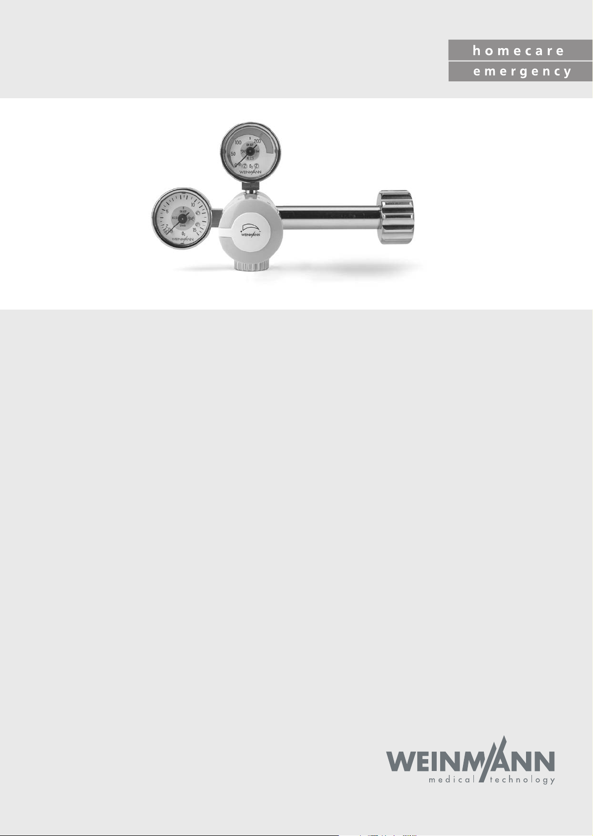
OXYWAY
Single-stage pressure reducer, fixed:
Fix I; Fix I side outlet; Fix II; Fix III; Fix III left
Single-stage pressure reducer, variable:
Fine I; Fine II; Fine III
Single-stage pressure reducer, indexed:
Fast I; Fast II; Fast II High Flow; Fast III
Indexed flowmeter OXYWAY Click
Two-stage pressure reducer, fixed:
OXYTRON
Service and Repair Instructions
Page 2

Contents
Introduction . . . . . . . . . . . . . . . . . . . . . . . . . 3
1. Overview . . . . . . . . . . . . . . . . . . . . . . . . . . . 4
1.1 Explanation of Numbers . . . . . . . . . . . .6
1.2 Information about conformity with
standards . . . . . . . . . . . . . . . . . . . . . .6
2. Function . . . . . . . . . . . . . . . . . . . . . . . . . . . . 7
2.1 General. . . . . . . . . . . . . . . . . . . . . . .7
2.2 Fixed pressure reducer FIX
(WM 30050; 30100; 30200;
30300; 30350) . . . . . . . . . . . . . . . . .7
2.3 Variable pressure reducer FINE
(WM 30500; 30700; 30750). . . . . . .8
2.4 Indexed pressure reducer FAST
(WM 30600; 30800; 30850). . . . . . .8
2.5 Multistep pressure reducer Fast II High
Flow (WM 31899) . . . . . . . . . . . . . . .8
2.6 Two-stage pressure reducer OXYTRON
(WM 30150). . . . . . . . . . . . . . . . . . .9
2.7 Indexed flowmeter OXYWAY Click . . . . .9
2.8 Oxygen outlets pressure reducer
OXYWAY . . . . . . . . . . . . . . . . . . . . 10
3. Final Check . . . . . . . . . . . . . . . . . . . . . . . . . 11
3.1 General. . . . . . . . . . . . . . . . . . . . . .11
3.2 Intervals . . . . . . . . . . . . . . . . . . . . . .11
3.3 Performing check . . . . . . . . . . . . . . . .12
3.4 Checking the adjustable output (flow)
on the OXYWAY Click . . . . . . . . . . . .15
4. Servicing . . . . . . . . . . . . . . . . . . . . . . . . . . 16
4.1 General. . . . . . . . . . . . . . . . . . . . . .16
4.2 Intervals and scope for OXYWAY and
OXYTRON pressure reducers . . . . . . . . 16
4.3 Intervals and scope for OXYWAY Click
flowmeter . . . . . . . . . . . . . . . . . . . . .16
4.4 Storage . . . . . . . . . . . . . . . . . . . . . .17
4.5 Disposal . . . . . . . . . . . . . . . . . . . . .17
5. Troubleshooting . . . . . . . . . . . . . . . . . . . . . 18
5.1 Pressure reducer OXYWAY and
OXYTRON . . . . . . . . . . . . . . . . . . . . 18
5.2 Flowmeter OXYWAY Click . . . . . . . . .19
6. Repair Information and Repair Instructions
for pressure reducer OXYWAY and
OXYTRON . . . . . . . . . . . . . . . . . . . . . . . . . 20
6.1 General. . . . . . . . . . . . . . . . . . . . . .20
6.2 Replacing sealing ring in connector. . . . 20
6.3 Replacing filter screw . . . . . . . . . . . . .21
6.4 Replacing oxygen outlet . . . . . . . . . . .21
6.5 Replacing gage . . . . . . . . . . . . . . . .27
6.6 Replacing piston in pressure reducer
FIX (WM 30050, 30100, 30200,
30300, 30350) . . . . . . . . . . . . . . . .28
6.7 Replacing piston in pressure reducer
FINE (WM 30500, 30700, 30750) . .30
6.8 Replacing piston in pressure reducer
FAST (WM 30600, 30800, 30850) . .33
6.9 Replacing piston in pressure reducer
Fast II High Flow (WM 31899) . . . . . .36
6.10 Replacing index head / cover . . . . . . .39
6.11 Replacing index head/cover on Fast II
High Flow pressure reducer . . . . . . . . .45
6.12 Replacing Connector and Sinter Filter . . 50
6.13 Changing connector and sinter filter in
OXYTRON pressure reducer . . . . . . . .52
6.14 Replacing second stage of OXYTRON
pressure reducer (WM 30150) . . . . . .54
6.15 Replacing first-stage piston in OXYTRON
pressure reducer (WM 30150) . . . . . .55
6.16 Replacing second-stage piston in
OXYTRON pressure reducer
(WM 30150). . . . . . . . . . . . . . . . . . 56
7. Repair Information and Repair Instructions for
flowmeter OXYWAY Click . . . . . . . . . . . . . . 58
7.1 General. . . . . . . . . . . . . . . . . . . . . .58
7.2 Replacing index head / cover . . . . . . .58
7.3 Changing filter screw . . . . . . . . . . . . .63
7.4 Replace central gas supply system plug
connection . . . . . . . . . . . . . . . . . . . .63
8. Replacement Parts . . . . . . . . . . . . . . . . . . . 64
8.1 Information about conformity with
standards. . . . . . . . . . . . . . . . . . . . .64
8.2 Replacement parts list for all
pressure reducers. . . . . . . . . . . . . . . .65
8.3 Additional replacement parts for
WM 30050 . . . . . . . . . . . . . . . . . .66
8.4 Additional replacement parts for
WM 30100, 30150, 30200, 30300 67
8.5 Additional replacement parts for
WM 30500, 30700, 30750 . . . . . .68
8.6 Additional replacement parts for
WM 30800, 30850 . . . . . . . . . . . .69
8.7 Additional replacement parts for
WM 31899 . . . . . . . . . . . . . . . . . .70
8.8 Additional replacement parts for
WM 30600 . . . . . . . . . . . . . . . . . .71
8.9 Additional replacement parts for
OXYWAY Click . . . . . . . . . . . . . . . .72
8.10 Additional replacement parts 2nd stage
OXYTRON WM 30150. . . . . . . . . . .73
8.11 Connections for pressure reducer . . . . .74
9. Tools, Inspection/Measuring/Test Equipment 76
9.1 General tools and resources . . . . . . . .76
9.2 Special tools. . . . . . . . . . . . . . . . . . . 76
9.3 Inspection, measuring and test
equipment . . . . . . . . . . . . . . . . . . . .77
10. Technical Data . . . . . . . . . . . . . . . . . . . . . . 79
10.1 Pressure reducer OXYWAY up to
SN 0849999 and OXYTRON . . . . . .79
10.2 Pressure reducer OXYWAY from
SN 0850000 . . . . . . . . . . . . . . . . .80
10.3 Technical Data for flowmeter
OXYWAY Click . . . . . . . . . . . . . . . .81
11. Technical amendments . . . . . . . . . . . . . . . . 82
© Copyright WEINMANN GmbH & Co. KG.
The content and presentation are copyright protected and may only be used by authorised WEINMANN Service Partners in
the course of their service operations. The content must not be reproduced or passed on to third parties. The complete documents
must be returned on termination of the cooperation with WEINMANN.
2
Page 3

Introduction
For many decades WEINMANN has developed,
produced and marketed appliances for oxygen
therapy, inhalation therapy and emergency
medicine.
In 1957 WEINMANN put the first diaphragm
pressure reducer on the market.
Pressure reducers are used in medical oxygen
inhalation. They reduce the pressure delivered by
oxygen bottles from 200 bar to the specified
operating pressure.
The flowmeter is used during the inhalation of medical oxygen via the central gas supply system of a
hospital, for example.
Pressure reducers are a functional component of a
wide range of appliance combinations such as
stationary oxygen appliances and portable oxygen devices. They are therefore an important
component in the treatment of chronic respiratory
diseases and/or disorders of the cardiovascular
system.
The aim of these Service and Repair Instructions is to
familiarize you, a
the function, technology, servicing and repair of
pressure reducers and flowmeters. In conjunction
with a training course that you have already been
trained and competent expert,
with
given by WEINMANN, you now belong to that
group of “trained and competent experts”, which
means you can give your customers proper instruction, rectify faults yourself and perform the prescribed functional check and any repairs in
accordance with these Service and Repair Instructions.
In the event of any warranty claim the device must be
sent to WEINMANN
So that we can process any warranty claims or
requests for favorable treatment, please send us
the customer’s purchase slip (invoice) with the
appliance.
Repairs and/or repair work may only be performed by WEINMANN or by trained and competent experts.
You are responsible for any repairs you carry out
yourself and the relevant guarantees!
Only genuine WEINMANN replacement parts
used for repairs.
Please remember:
Your customers put their trust in you and rely on
your efficiency, just as you rely on WEINMANN.
.
may be
Note:
You will find the following information in the operating instructions for the devices:
• Safety information
• Assembly
• Operation
• Hygienic preparation
• Functional Check
• Warranty.
Introduction
3
Page 4
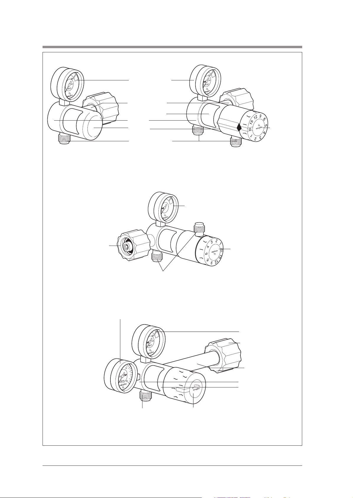
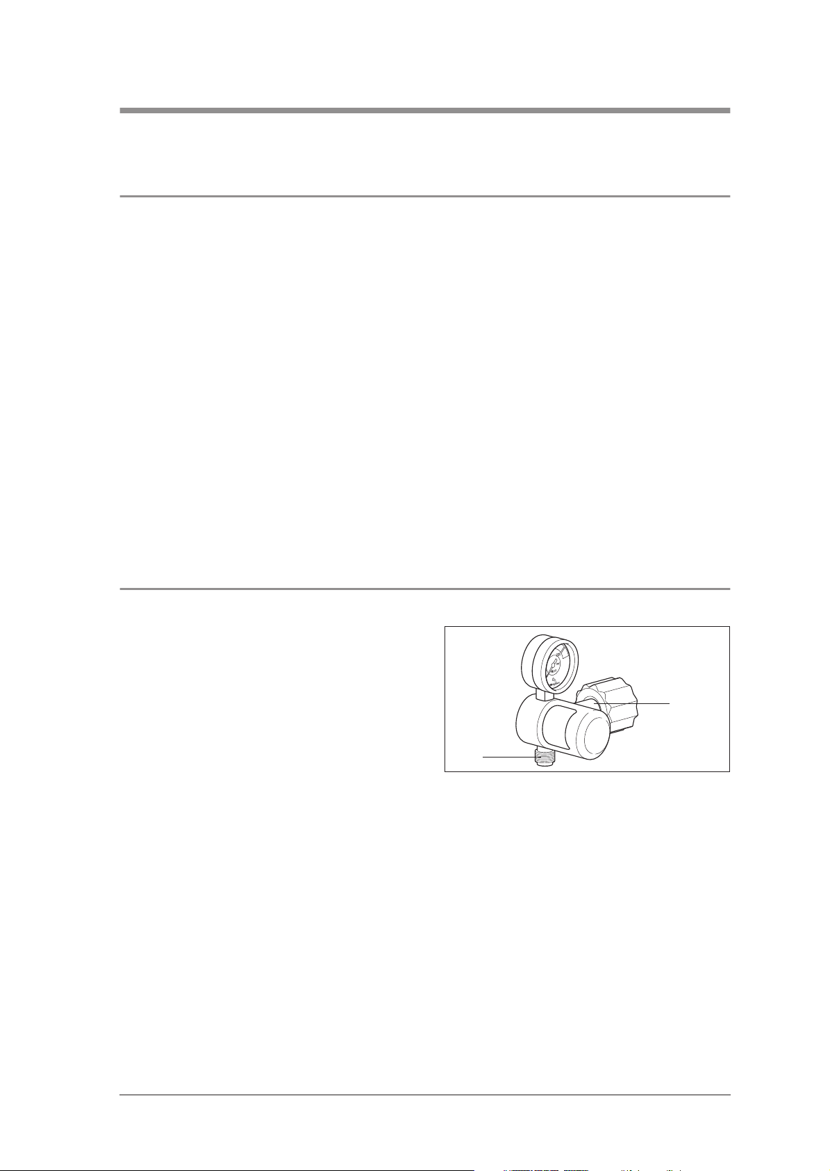
1. Overview
1 Contents gage
2 Connector
(oxygen bottle)
3 Rating plate
4 Body
22 Cover
Oxygen outlet
(to consumer)
6 Index head
Fixed pressure reducer FIX
WM 30050; 30100; 30200;
30300; 30350
2 Connector (oxygen
bottle)
Multistep pressure reducer Fast II High Flow
WM 31899
8 Flow gage
Indexed pressure reducer FAST
WM 30600; 30800; 30850
1 Contents gage
6 Index head
Oxygen outlet
(to consumer)
1 Contents gage
15 Connection nut
2 Connector (oxygen
bottle)
4 Body
22 Cover
Oxygen outlet
(to consumer)
9 Adjuster knob
Variable pressure reducer FINE
WM 30500; 30700; 30750
4
Overview
Page 5
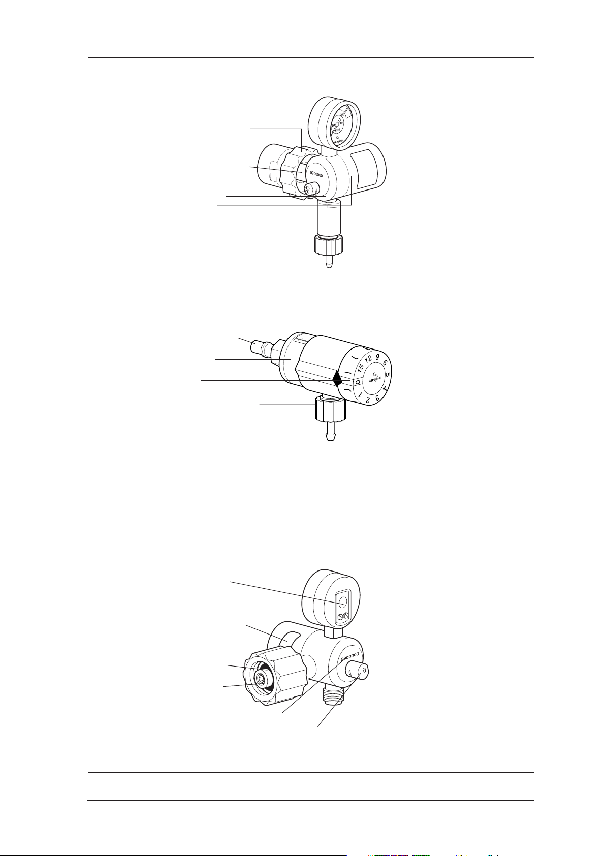
1 Contents gage
15 Connection nut
2 Connector (oxygen
bottle)
4 Body
22 Cover
52 Body stage 2
Oxygen outlet
(to consumer)
Two-stage pressure reducer
OXYTRON WM 30150
2 Connector
22 Cover
3 Rating plate
6 Index head
13 Service plate
20 Plate for changing
filter screw
14 Sealing ring
Oxygen outlet
(to consumer)
Indexed flowmeter
OXYWAY Click WM 31030
12 Filter screw
10 Appliance number
11 Safety valve
Rear view of pressure reducer
Overview
5
Page 6
1.1 Explanation of Numbers
Type: 30800
The type row indicates the basic design of the
pressure reducer, e.g. “30800” for indexed
pressure reducers (Fast I).
Order number:
In the order number the first three numbers are a
short indication of the type, and the last two digits
indicate the specific version (e.g. the connection
variants).
Appliance number:
The first two digits of the appliance number show
the year of manufacture. The next five digits are the
consecutive appliance serial number within each
type. The appliance number is stamped on the
back of the pressure reducer.
1.2 Information about conformity with standards
Up to serial number 0849999, OXYWAY
pressure reducers meet standard EN 738-1.
From serial number 0850000, OXYWAY
pressure reducers meet standard EN ISO 105241:2006.
In the course of adapting the products to standard
EN ISO 10524-1:2006, it was not possible to
design all components to be downward-compatible. Parts which are not downward-compatible are
available for both device statuses separately and
are marked accordingly in the replacement parts
lists (see “8. Replacement Parts” on page 64) of
these instructions.
• Fit replacement parts which are not downward-compatible only
pressure reducer serial numbers quoted.
• Do not convert pressure reducers up to
SN 0849999 “to suit the new standard”.
in accordance
with the
Caution!
Malfunction as a result of unclear device status.
If replacement parts which are not downward-compatible are used in the wrong pressure reducers,
connected devices will malfunction.
6
Overview
Page 7
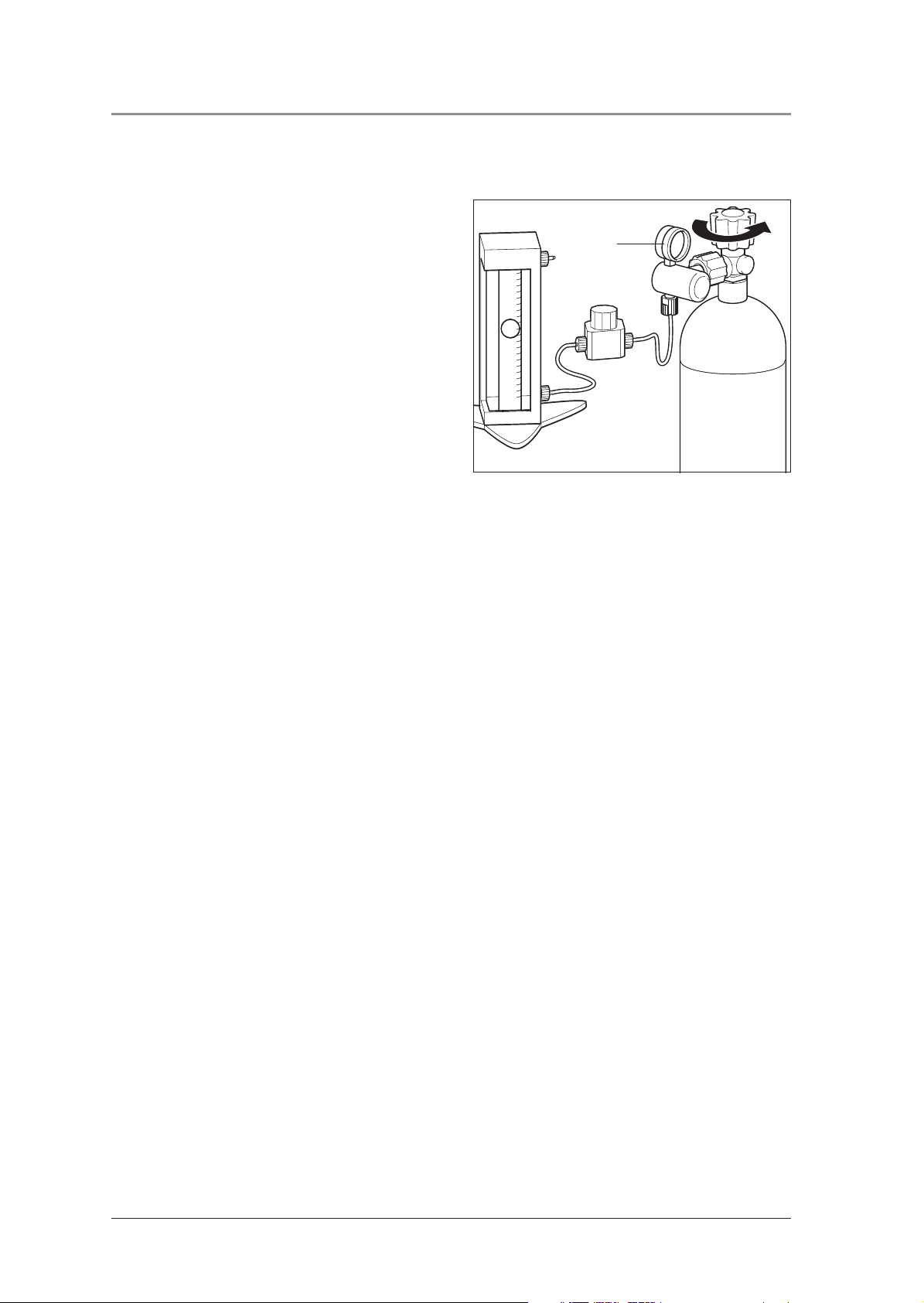
2. Function
2.1 General
During operation, the oxygen coming from the
oxygen bottle passes through the bottle valve and
the connector 2 into the body 4 of the pressure
reducer. You can read off the bottle pressure (delivery pressure) at the contents gage 1.
WEINMANN piston pressure reducers are of
modular design. This makes it possible to keep the
number of replacement parts to a minimum.
A filter screw with integrated sinter filter (see explanation on right) traps any impurities. A further sinter
filter absorbs pressure surges in the oxygen flow.
The filter screw 12 is located at the entrance to the
connector 2. The second sinter filter is fitted between
the connector 2 and the body 4.
In the reduction stage the bottle pressure is reduced
to the required nominal outlet pressure, depending
on type. The principle used, with crater drill hole
and spring-loaded piston, ensures especially constant pressure in spite of variations in flow.
All pressure reducers are protected against excess
pressure by a safety valve 11.
Explanations:
Sinter filter: Small spherical bronze particles are
pressed together under heat, creating a filter with a
particularly fine pore structure (50 - 75 µm).
Flow: Outlet volume; expressed in liters per minute.
2.2 Fixed pressure reducer FIX
(WM 30050; 30100; 30200; 30300; 30350)
A fixed orifice in oxygen outlet 7 creates a constant
flow.
The pressure reducers in this series differ in the
length and position of the connector 2 and the
oxygen outlet 7.
2
7
Function
7
Page 8
2.3 Variable pressure reducer FINE (WM 30500; 30700; 30750)
The piston is acted upon by a second spring which
can be adjusted via a spindle system and thereby
creates different outlet pressures. In conjunction
with the fixed orifice in the oxygen outlet 7 you can
therefore make continuously variable adjustments
to the flow. You can read off the flow setting at the
flow gage 8.
8
2
The pressure reducers in this series differ in the
length and position of the connector 2.
7
2.4 Indexed pressure reducer FAST (WM 30600; 30800; 30850)
As in the fixed pressure reducers, this creates a
constant operating pressure (outlet pressure).
The index head 6 contains an orifice disc with
various orifice diameters which are aligned by an
index (click-in) system with the oxygen outlet 35.
This enables you to set various flow rates.
The pressure reducers in this series differ in the
length and position of the connector 2. A pressure
reducer of type WM 30850 has two oxygen
outlets.
7
35
2
6
2.5 Multistep pressure reducer Fast II High Flow (WM 31899)
As in the Fast multistep pressure reducers, there is an
orifice disk with a variety of orifice diameters in adjuster 6 which is brought into line with oxygen outlet 35
by means of a locating system.
35
In addition to the flow outlet, there is a pressure outlet
for medical devices with an oxygen requirement in excess of 90 l/min. The pressure outlet and the flow outlet may not be in operation simultaneously.
7
6
8
Function
Page 9
2.6 Two-stage pressure reducer OXYTRON (WM 30150)
The two-stage pressure reducer has a first stage in
the form of a fixed pressure reducer WM 30100,
and a second reduction stage 52 to permit optimal
adjustment of pressure and flow to suit the
OXYTRON oxygen device.
In the second stage the pressure of 4.5 bar from
the first stage is similarly reduced by a system of
crater drill hole and spring-loaded pistion to
1.6 bar.
A fixed orifice in the oxygen outlet 7 generates a
constant flow of 12 l/min.
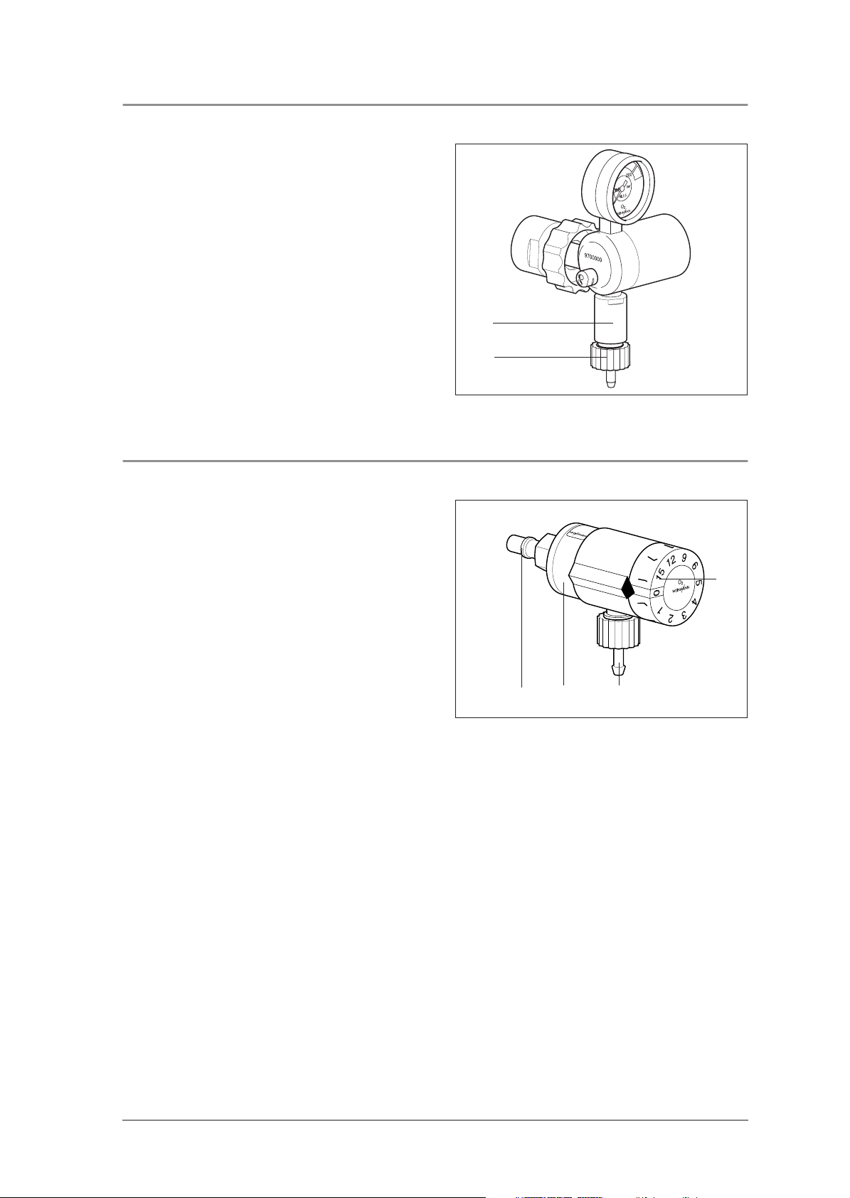
2.7 Indexed flowmeter OXYWAY Click
During operation, the oxygen supplied by the central
gas system at a pressure of 4.5 bar passes through the
inlet connector 2 into the body 22 of the OXYWAY
Click.
The dial head 6 contains an orifice disk with orifices of different diameters which are lined up with
the oxygen outlet 35 by means of a click dial system. You can set the following flow rates: 1, 2, 3,
4, 5, 6, 9, 12, 15 l/min..
52
7
2 35
6
22
Function
9
Page 10
2.8 Oxygen outlets pressure reducer OXYWAY
Oxyway pressure reducers are available with different oxygen outlets: the pressure outlet and the
flow outlet are different (see also “10. Technical
Data” on page 79).
Flow outlets are intended for the direct supply of
the patient, e.g. via nasal cannula, mask or
Flow outlet
(Fix I, Lateral outlet Fix I)
9/16 UNF thread
Pressure and flow outlet
(Fast II)
(Fine I up to III)
9/16 UNF thread
Pressure and flow outlet
(Fast II High Flow)
intermediate humidifier. Flow outlets have a 9/16
UNF thread.
Pressure outlets are intended to supply ventilators
such as the Medumat, modules or distributor bars.
Pressure outlets have a G 3/8" thread.
Flow outlet
Flow outlet
(Fast I and III)
9/16 UNF thread
Pressure outlet
(Fix III, Fix III left)
G 3/8"
thread
9/16 UNF
thread
Flow outlet
(Oxytron)
18 x 11 thread
G 3/8"
thread
G 3/8" thread
9/16 UNF
thread
Flow outlet
(Oxyway Click)
9/16 UNF thread
10
Function
Page 11

3. Final Check
3.1 General
Test conditions:
• Ambient temperature: 15 °C
• Ambient pressure: 1013 hPa
• Connection to oxygen supply. For flow tests, a
constant pressure* of 100 bar or 200 bar is
required.
* 100 bar up to SN 0849999
200 bar from SN 0850000
All the tolerances listed in these instructions (see
“10. Technical Data” on page 79) relate to these
conditions. Note that if different ambient conditions prevail, deviating measuring results may be
obtained.
For the check you will need:
• shutoff valve (max. 6 bar) after oxygen outlet
• test pressure gage 0 - 10 bar
• test pressure gage 0 - 2.5 bar
and three flow meters:
• 0 - 50 ml/min
• 0 - 20 l/min
• 0 - 220 l/min.
If the final check reveals faults, the device must not
be used until the defect has been rectified. For possible causes of the defect and how to remedy
them, see Chapter “5. Troubleshooting” on
page 18.
A complete check of the OXYWAY Fix, Fast and
Fine pressure reducer includes:
• Visual inspection for mechanical damage,
• “3.3.1 Testing system for leaks” on page 12,
• “3.3.2 Testing safety valve for leaks” on
page 13,
• “3.3.3 Checking “0” position of contents
gage” on page 13,
• “3.3.4 Checking “0” position of flow gage on
pressure reducer FINE” on page 13
• “3.3.5 Checking for leaks with valve closed
on pressure reducer FINE” on page 14,
• “3.3.6 Checking adjustable flow rate on pressure reducer FINE” on page 14,
• “3.3.7 Checking adjustable flow rate on pressure reducer FAST” on page 14.
• “3.3.8 Checking constant flow rate in pressure reducers FIX, FAST and
FAST II high Flow” on page 15
• “3.3.9 Checking static outlet pressure p4 for
all pressure reducers” on page 15.
A complete check of the OXYWAY Click flowmeter includes:
• “3.4 Checking the adjustable output (flow)
on the OXYWAY Click” on page 15.
We recommend that you always keep in stock:
• Replacement seal set WM 1148,
• Filter screw WM 30905.
3.2 Intervals
After any servicing or repair work
• Perform a final check.
Final Check
11
Page 12
3.3 Performing check
3.3.1 Testing system for leaks
1. Close system after pressure reducer, e.g. by
closing a valve after the pressure reducer.
2. Check that all screwed joints and hoses are
firmly seated. If necessary tighten joints by
hand.
3. Slowly open valve of oxygen bottle. Contents
gage 1 of pressure reducer now shows bottle
pressure, e.g. 200 bar.
4. To detect leaks, wet screwed connections with
a soap-and-water solution. Use Lanosan
for this purpose.
Warning!
Risk of explosion from soap penetration.
Leaks can cause soap to penetrate the system
and combine with the oxygen to form an explosive mixture.
• Open the O2 valve before wetting parts of the
system with a soap-and-water solution. The
system is then pressurized. No soap can penetrate the system.
• Remove the soap-and-water solution without
leaving any residues after the test is complete.
5. Close bottle valve again.
6. Observe needle of contents gage 1 for about
1 minute. If needle stays in same position, the
system is gas-tight. If the needle falls steadily,
there is a leak.
®
med
1
Eliminating leaks
We recommend that you keep a stock of replacement seals for the connections.
1. Prepare solution of soapy water, using perfume-free soap.
2. Wet all screwed joints with solution. If bubbles
form, this indicates a leak.
3. Release pressure in system:
– Close oxygen bottle valve.
– Open valve after pressure reducer until
contents gage 1 reads “0”.
12 Final Check
4. Replace faulty seal responsible for leak (see
“6.2 Replacing sealing ring in connector” on
page 20).
Important!
Screwed joints of oxygen line must only be hand
tightened.
5. Check for leaks again.
6. If leak cannot be eliminated, unit must be
repaired.
Page 13
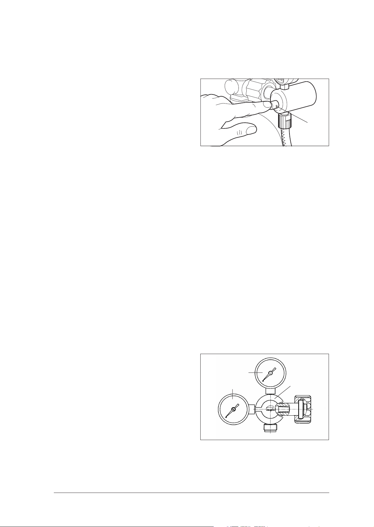
3.3.2 Testing safety valve for leaks
1. Test must be performed at maximum flow. In
the Fine and Fast series this is set accordingly.
2. Slowly open oxygen bottle valve.
3. Test with finger whether oxygen is escaping
from safety valve 11.
If oxygen is escaping, have pressure reducer
repaired by manufacturer (WEINMANN).
Alternatively, you can also wet the safety valve
with soap-and-water solution to find leaks. Use
Lanosan® med.
Warning!
Risk of explosion from soap penetration.
Leaks can cause soap to penetrate the system
and combine with the oxygen to form an explosive mixture.
• Open the O2 valve before wetting parts of the
system with a soap-and-water solution. The
system is then pressurized. No soap can
penetrate the system.
• Remove the soap-and-water solution without
leaving any residues after the test is complete.
11
3.3.3 Checking “0” position of contents gage
1. Slowly open oxygen bottle valve.
Contents gage
1 now shows bottle pressure.
2. To release pressure in system:
– Close oxygen bottle valve
– Switch on connected appliance
– Open shutoff valve after oxygen outlet.
3. Needle of contents gage
“0”. Wait until needle stops moving. Now
switch appliance off.
4. Check whether needle points exactly to “0”.
If not, fit replacement contents gage (see “6.5
Replacing gage” on page 27).
3.3.4 Checking “0” position of flow gage on pressure reducer FINE
1. Slowly open oxygen bottle valve.
2. Set flow rate (e.g. 7 l/min) at adjuster knob
You can read the set value at the flow gage 8.
3. To release pressure in system:
– Close oxygen bottle valve
– Open shutoff valve after oxygen outlet
– Switch on connected appliance.
4. Needle of flow gage 8 now falls toward “0”.
Wait until needle stops moving. Now switch
appliance off.
9.
1
8
1 now falls toward
9
5. Check whether needle points exactly to “0”.
If not, fit replacement gage (see “6.5 Replacing gage” on page 27).
Final Check 13
Page 14

3.3.5 Checking for leaks with valve closed on pressure reducer FINE
You need a flow meter with a range of 0 – 50 ml/min.
Perform measurement at an inlet pressure of 200 bar.
1. Slowly open oxygen bottle valve.
Contents gage 1 now shows bottle pressure.
2. Check whether flow gage 8 shows a flow rate
of “0”.
If not, use adjuster knob 9 to set flow rate to
“0”.
3. Connect flow meter (0 - 50 ml/min) to oxygen
outlet 7.
4. Wait until flow meter shows constant reading.
5. Read off value.
If value is greater than 30 ml/min, fit replacement piston (see “6.7 Replacing piston in pressure reducer FINE (WM 30500, 30700,
30750)” on page 30).
3.3.6 Checking adjustable flow rate on pressure reducer FINE
You need a flow meter with a range of 0 – 20 l/min.
Perform measurement at an inlet pressure of 100 bar ± 10 bar.
1. Slowly open oxygen bottle valve.
Contents gage 1 now shows bottle pressure.
2. Turn adjuster knob 9 to the left as far as it will
go, until flow gage 8 shows a flow rate of “0”.
3. Connect flow meter to oxygen outlet 7.
4. Set any desired flow rate at adjuster knob 9.
Note: Checking the flow of the second oxygen outlet is described in a later section (3.3.8, page 15).
5. Check on flow meter whether actual value
agrees with set value.
Note tolerances of pressure reducer:
1 to 5 l/min: ± 0.5 liters,
6 to 15 l/min: ± 10 %.
6. If any value does not agree, have pressure reducer repaired by manufacturer
(WEINMANN).
3.3.7 Checking adjustable flow rate on pressure reducer FAST
You need a flow meter with a range of 0 – 20 l/min.
Perform measurement at an inlet pressure of 100 bar ± 10 bar.
1. Slowly open oxygen bottle valve.
Contents gage 1 now shows bottle pressure.
2. Set flow of “0” at index head 6.
3. Connect flow meter to oxygen outlet 7.
4. Set any desired flow rate at index head 6.
Note: Checking the flow of the second oxygen outlet is described in a later section (3.3.8, page 15).
5. Check on flow meter whether actual value
agrees with set value.
Note tolerances of pressure reducer:
1 to 5 l/min: ± 0.5 liters,
6 to 15 l/min: ± 10 %.
6. If any value does not agree, have pressure
reducer repaired by manufacturer
(WEINMANN).
14 Final Check
Page 15

3.3.8 Checking constant flow rate in pressure reducers FIX, FAST and
FAST II high Flow
You need a flow meter as follows:
• For WM 30050, 30100, 30150: flow meter 0 – 20 l/min
• For WM 30200, 30300, 30350, 30850, 31899: flow meter 0 – 220 l/min.
1. Connect flow meter to oxygen outlet.
2. Close
– on pressure reducers WM 30850 and
WM 31899: oxygen outlet for adjustable
flow,
– on pressure reducer WM 30200: second
oxygen outlet (on the side).
3. Slowly open oxygen bottle valve.
– Contents gage 1 now shows bottle pressure
– Flow meter shows flow rate.
4. Check flow rate reading against set value.
Pressure reducers must maintain the following
flow rates:
WM 30050, 30100: 4 l/min ± 0.5 l/min
WM 30150: 12 l/min ± 1.2 l/min
WM (30200), 30300,
30350: 120 l/min ± 15 l/min
WM 30850: 90 l/min ± 10 l/min
WM 31899: min. 160 l/min
5. In the event of discrepancies, have pressure reducer repaired by manufacturer
(WEINMANN).
6. There is a second oxygen outlet on pressure
reducer WM 30200. This is a free pressure
outlet.
3.3.9 Checking static outlet pressure p4 for all pressure reducers
1. Connect appropriate test gage to oxygen
outlet 7.
2. Check closing pressures p4 (see “10. Technical Data” on page 79). They are valid for a
delivery pressure of p
* = 100 bar or
1
200 bar and must be reached within 1 minute
at most. After this they must not show any further increase.
* 100 bar up to SN 0849999
200 bar from SN 0850000
3.4 Checking the adjustable output (flow) on the OXYWAY Click
You need a flow meter with a range of 0 – 20 l/min.
Perform the measurement at an inlet pressure of 4.5 bar ±0.2 bar.
1. Set the flow "0" at index head 6.
2. Plug the flowmeter into a suitable compressed
gas supply (e.g. a central gas supply system).
3. Connect the flow meter to the oxygen outlet.
4. Set any flow value at index head 6.
5. Check on the flow meter whether the set value
corresponds to the actual value.
Please observe the tolerances of the flowmeter in
the process.
Rising test:
1 to 5 l/min: ±0.5 liter,
6 to 15 l/min: ±10 %.
Falling test:
6 ±10 % and 0/min: ±0.15 l/min
Final Check 15
Page 16

4. Servicing
4.1 General
We recommend that all maintenance work, such
as inspections and repairs, be carried out by the
manufacturer (WEINMANN) or by expert technical personnel trained by WEINMANN.
When carrying our repairs, be sure to observe the
directions in these Service and Repair Instructions.
4.2 Intervals and scope for OXYWAY and OXYTRON pressure
reducers
In cases of dirt accumulation, or at least every 2 years:
1. Fit replacement filter screw 12 (see “6.3 Re-
placing filter screw” on page 21).
Every 4 years
1. Fit replacement filter screw 12 (see “6.3 Re-
placing filter screw” on page 21);
2. Completely replace piston 16.
– For pressure reducers WM 30050,
30100, 30200, 30300 and 30350:
see Section 6.6, page 28,
– For pressure reducers WM 30500,
30700, 30300 and 30750:
see Section 6.7, page 30,
– For pressure reducers WM 30600;
30800, 30850:
see Section 6.8, page 33;
2. Perform a functional check (see “6. Functional
Check“ on page 12 of the Operating Instructions”).
– For pressure reducers WM 31899;
30800, 30850:
see Section 6.9, page 36;
3. Fit replacement sinter filter 19 (see “6.12 Replacing Connector and Sinter Filter” on
page 50);
4. Fit replacement sealing ring 14 (see “6.2 Replacing sealing ring in connector” on
page 20)
5. Perform a final check (see “3. Final Check” on
page 11). If you find any faults, rectify them.
6. Replace service plate 13 with a new one with
the new data from “8. Replacement Parts” on
page 64.
4.3 Intervals and scope for OXYWAY Click flowmeter
Check metering accuracy by having a check measurement performed every 4 years.
We recommend that repair work be performed
only by the manufacturer, WEINMANN, or by
trained qualified experts expressly authorized by
WEINMANN.
16 Servicing
Page 17

4.4 Storage
If the pressure reducer is to remain unused for long periods, we recommend the following procedure:
1. Clean pressure reducer (see “Hygienic
preparation” in the Operating Instructions).
2. Store pressure reducer in a dry place.
4.5 Disposal
Do not dispose of the unit with domestic
waste. To dispose of the unit properly,
please contact a licensed, certified
electronic scrap disposal merchant. This
address is available from your Environment Officer or from your local authority.
Important:
Be sure to observe the servicing intervals for stored appliances as well. Otherwise the appliance is no longer
fit for use on removal from storage.
Servicing 17
Page 18

5. Troubleshooting
5.1 Pressure reducer OXYWAY and OXYTRON
Fault Cause Remedy
Replace sealing ring
(Section 6.2, page 20).
Replace connector
(Section 6.12, page 50).
Replace sealing ring
(Section 6.2, page 20).
Replace piston
(Section 6.6, page 28 or
Section 6.7, page 30 or
Section 6.8, page 33).
Have pressure reducer repaired by
manufacturer (WEINMANN).
Replace pressure gage
(Section 6.5, page 27).
Replace oxygen outlet
(Section 6.4, page 21)
Replace index disc (Section 6.9,
page 36)
Replace index disc (Section 6.9,
page 36)
Leak at connector
(bottle connection).
Leak at oxygen outlet
(appliance connection).
Leak at relief valve.
Pressure gage does not read
“0” at zero pressure.
Outlet flow rate too low.
Damaged sealing ring.
Damaged seat for connector sealing
ring.
Damaged sealing ring.
Unacceptable pressure rise in
pressure reducer (delayed rise
effect).
Relief valve not gas-tight.
Crater in body faulty.
Pressure gage faulty.
Oxygen outlet faulty.
Index disk faulty.
Index disk incorrectly adjusted.
Outlet flow rate of OXYTRON
WM 30150 outside
tolerance of
12 l/min ± 1.2 l/min
Outlet pressure of OXYTRON
WM 30150 outside
tolerance of
1.5 bar ± 0.08 bar
Variable pressure reducer:
leak at oxygen outlet 7
> 30 ml/min
(with valve closed and
200 bar bottle pressure).
Second stage faulty
Unacceptable pressure rise in
pressure reducer.
Replace complete piston
(Section 6.16, page 56)
Replace piston
(Section 6.6, page 28 or
Section 6.7, page 30 or
Section 6.8, page 33)
or
have pressure reducer repaired by
manufacturer (WEINMANN).
18 Troubleshooting
Page 19

5.2 Flowmeter OXYWAY Click
Fault Cause Remedy
Unusually high oxygen
consumption
Inadequate O2 supply during
inhalation
Flowmeter not working
Leak in system Find and eliminate leak
Leak in system Find and eliminate leak
Defect or internal soiling in
flowmeter
Flowmeter defective Have flowmeter repaired
Oxygen source defective or empty Check oxygen source
Have flowmeter repaired
Troubleshooting 19
Page 20

6. Repair Information and Repair Instructions for
pressure reducer OXYWAY and OXYTRON
6.1 General
• Observe the safety information on page 4 of the
Operating Instructions for OXYWAY.
• Caution: Risk of explosion!
To prevent explosion risks, make sure your
hands, tools and workplace are absolutely
free from oil and grease during the repair
work.
For this reason you should always wash your
hands before starting work.
• Any operations on the appliance presuppose
detailed knowledge and observance of the
Operating Instructions and the Service and
Repair Instructions.
• You should only carry out repairs described in
these Service and Repair Instructions. Otherwise proper functioning of OXYWAY cannot
be guaranteed.
• Be sure to perform a final check after every
• If you replace components or individual parts,
• If there is a fault in the body or the relief valve,
• Certain parts must be screwed up using a
• Note:
6.2 Replacing sealing ring in connector
repair (see “3. Final Check” on page 11).
always use genuine WEINMANN parts only.
have OXYWAY repaired by the manufacturer
(WEINMANN).
torque wrench. To ensure compliance with the
specified torque, check your torque wrench
regularly for torque compliance (control of inspection, measuring and test equipment).
The item numbers in the following text are the
same as the item numbers in the Replacement
Parts List on page 64 and the overview on
page 4.
Tools required:
• From tool set WM 15366:
– Watchmaker’s screwdriver WM 3004130041 (cleaned with methylated spirit).
1. Using a cleaned screwdriver, ease sealing
ring 14 carefully out of its groove.
Be careful not to damage the groove in any way.
2. If necessary, clean the groove with a dry cloth
or a cloth moistened with clean water.
3. Carefully press a new sealing ring into the
groove. Do not use any tools for this.
4. Perform a final check (see “3. Final Check” on
page 11).
14
20 Repair Information and Repair Instructions for pressure reducer OXYWAY and OXYTRON
Page 21
6.3 Replacing filter screw
Tools required:
• From tool set WM 15366:
– Allen wrench 4 mm WM 30042 (cleaned with methylated spirit).
1. If necessary, clean out the hexagonal socket of
the filter screw 12 with a small screwdriver.
2. Loosen the filter screw
12, but do not unscrew
it completely yet.
3. So that no dirt can fall into the pressure reducer,
hold it with the connector pointing down. In this
position, remove the filter screw
12.
4. Screw a new filter screw 12 into the connector
stub and tighten.
5. Perform a final check. Enter the change of filter
screw with date in the service record.
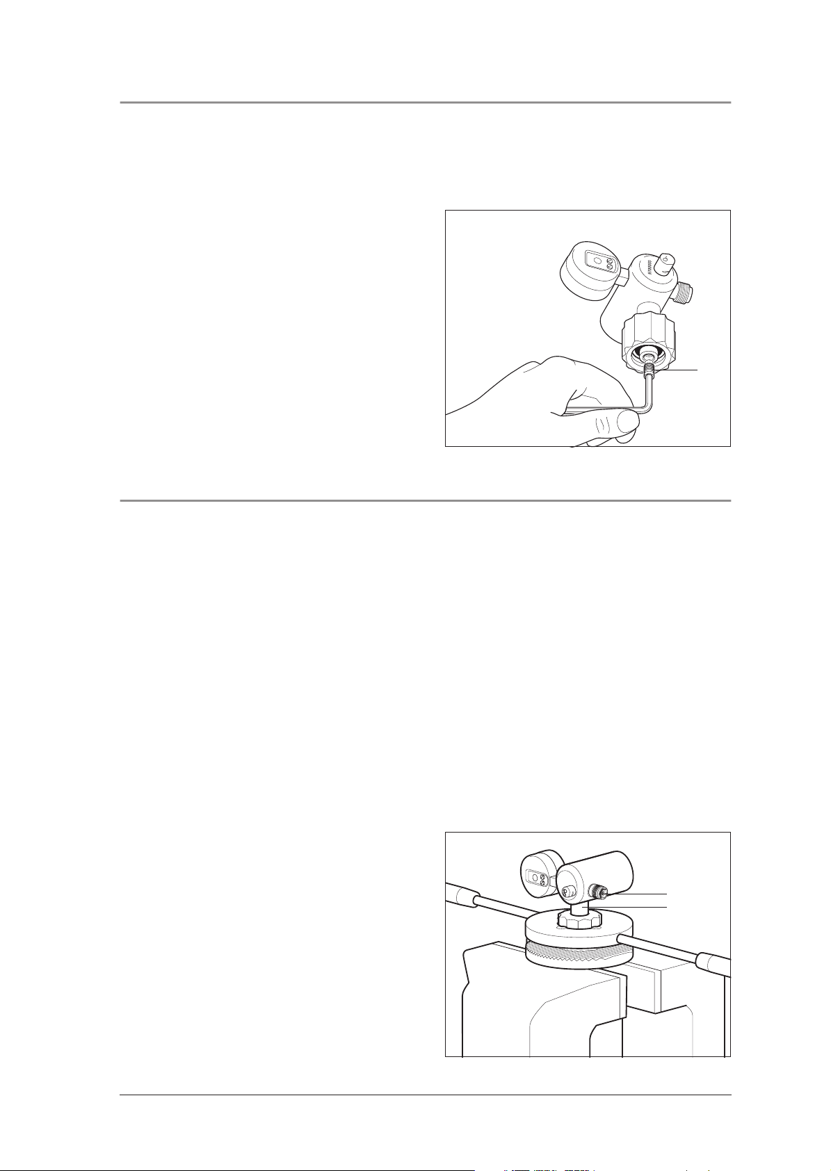
6.4 Replacing oxygen outlet
12
6.4.1 Replacing G 3/8 pressure outlet
Tools and material required:
• From tool set WM 15366:
– Counter tool with clamping handle WM 30035,
– Screwdriver bit 9 mm WM 30039 (cleaned with methylated spirit);
– Watchmaker’s screwdriver WM 30041 (cleaned with methylated spirit);
• Vise;
• Sealing ring
• Loctite 245 WM 14920 (never use other Loctite products).
• Torque wrench 25 Nm ± 1 Nm,
Note:
The oxygen outlet must always be replaced as a complete unit, because the flow rate cannot be guaranteed if
individual parts are replaced.
1. Clamp pressure reducer firmly in counter tool.
To do this, perform the following steps:
– Using a cleaned screwdriver, carefully ease
sealing ring 14 out of groove in connector.
Be careful not to damage the groove at all.
– Clamp bottom part of counter tool firmly in
a vise.
– Place the top part of the counter tool on the
bottom part of the counter tool.
– Screw the connection nut onto the bottom
part of the counter tool.
– Tighten the connection nut using the top part
of the counter tool.
14 (WM 1145);
7
2
Repair Information and Repair Instructions for pressure reducer OXYWAY and OXYTRON 21
Page 22
2. Using cleaned screwdriver bit, unscrew defective oxygen outlet 7 by turning to left.
3. Fit new oxygen outlet 7:
– Remove any adhesive residues from screw
threads. Use a brass wire brush for the external thread and if necessary a tap G 1/
8 for the internal thread.
Caution:
When cleaning threads, no dirt must enter
body of pressure reducer.
– Take a new oxygen outlet .
Caution:
The oxygen outlet must be clean and free
from oil and grease.
– Apply a little Loctite 245 to screw thread
with the exception of the first two turns.
The first two turns must be kept free of Loctite
to ensure that no Loctite enters the body of the
pressure reducer.
– Screw oxygen outlet 7 by hand into pres-
sure reducer.
– Tighten oxygen outlet 7 with 9 mm screw-
driver bit and a torque wrench
(25 Nm ± 1 Nm).
7
2
7
4. Release pressure reducer from counter tool.
5. If necessary, clean groove in connector
2 with
dry cloth or cloth moistened with clean water.
6. Now press
new sealing ring 14 carefully into
groove. Do not use any tools.
7. Perform a final check
(see “3. Final Check” on page 11).
6.4.2 Replacing UNF 9/16 flow outlet
Tools required:
• UNF 9/16 counter tool, consisting of:
– counter tool WM 14224
– locknut WM 14223
• special wrench SW 20/22, WM 22391
• counter tool WM 30035 (clamping handle not required)
• torque wrench with SW 22 open-end wrench insert.
Remove defective flow outlet
1. Screw locknut WM 14223 onto counter tool
WM 14224.
22 Repair Information and Repair Instructions for pressure reducer OXYWAY and OXYTRON
Page 23
2. Screw the UNF counter tool completely onto
the flow outlet of the pressure reducer.
3. Clamp the pressure reducer in a vise so that
only counter tool WM 14224 is actually in the
vise.
4. To clamp the defective flow outlet firmly in the
counter tool, turn locknut WM 14223 clockwise with a 22 mm open-end wrench.
5. To release the pressure reducer from the flow
outlet, turn the pressure reducer anticlockwise
by hand.
Repair Information and Repair Instructions for pressure reducer OXYWAY and OXYTRON 23
Page 24
6. Take the pressure reducer off the flow outlet.
7. To release the defective flow outlet in the
counter tool, turn locknut WM 14223 anticlockwise with the 22 mm open-end wrench.
8. Unscrew the defective flow outlet from the locknut.
Assembling new flow outlet
Caution:
When cleaning threads, no dirt must enter body
of pressure reducer.
1. Take a new oxygen outlet.
Caution:
The oxygen outlet
from oil and grease.
35 must be clean and free
2. Screw the new flow outlet fully into the counter
tool.
3. Wet about 2 threads of the new flow outlet
with Loctite 245 (WM 14920).
The first two turns must be kept free of Loctite to
ensure that no Loctite enters the body of the pressure reducer.
4. Clamp the counter tool in a vise so that only
counter tool WM 14224 is actually in the
vise.
5. To clamp the new flow outlet firmly in the
counter tool, turn the counter tool clockwise
with the 22 mm open-end wrench.
35
24 Repair Information and Repair Instructions for pressure reducer OXYWAY and OXYTRON
Page 25
6. Screw the pressure reducer onto the new flow
outlet hand-tight.
7. Take the pressure reducer with the counter tool
screwed onto it out of the vise.
8. Clamp counter tool WM 30035 in the vise.
9. Screw the pressure reducer and oxygen inlet
hand-tight to clamped counter tool WM
30035.
10. Put a torque wrench with open-end wrench insert SW 22 on counter tool WM 14224.
11. Tighten counter tool WM 14224 and thus the
new flow outlet on the pressure reducer
(torque: 25 Nm ±1 Nm).
12. Release the pressure reducer from counter tool
WM 30035.
13. Take counter tool WM 30035 out of the vise.
14. Clamp the pressure reducer in the vise so that
only counter tool WM 14224 is actually in the
vise.
Repair Information and Repair Instructions for pressure reducer OXYWAY and OXYTRON 25
Page 26
15. To release locknut WM 14223 from the flow
outlet, turn it anticlockwise with the 22 mm
open-end wrench.
16. Unscrew the pressure reducer and flow outlet
from locknut WM 14223.
17. Take the counter tool out of the vise.
18. Perform a final check
(see “3. Final Check” on page 11).
26 Repair Information and Repair Instructions for pressure reducer OXYWAY and OXYTRON
Page 27

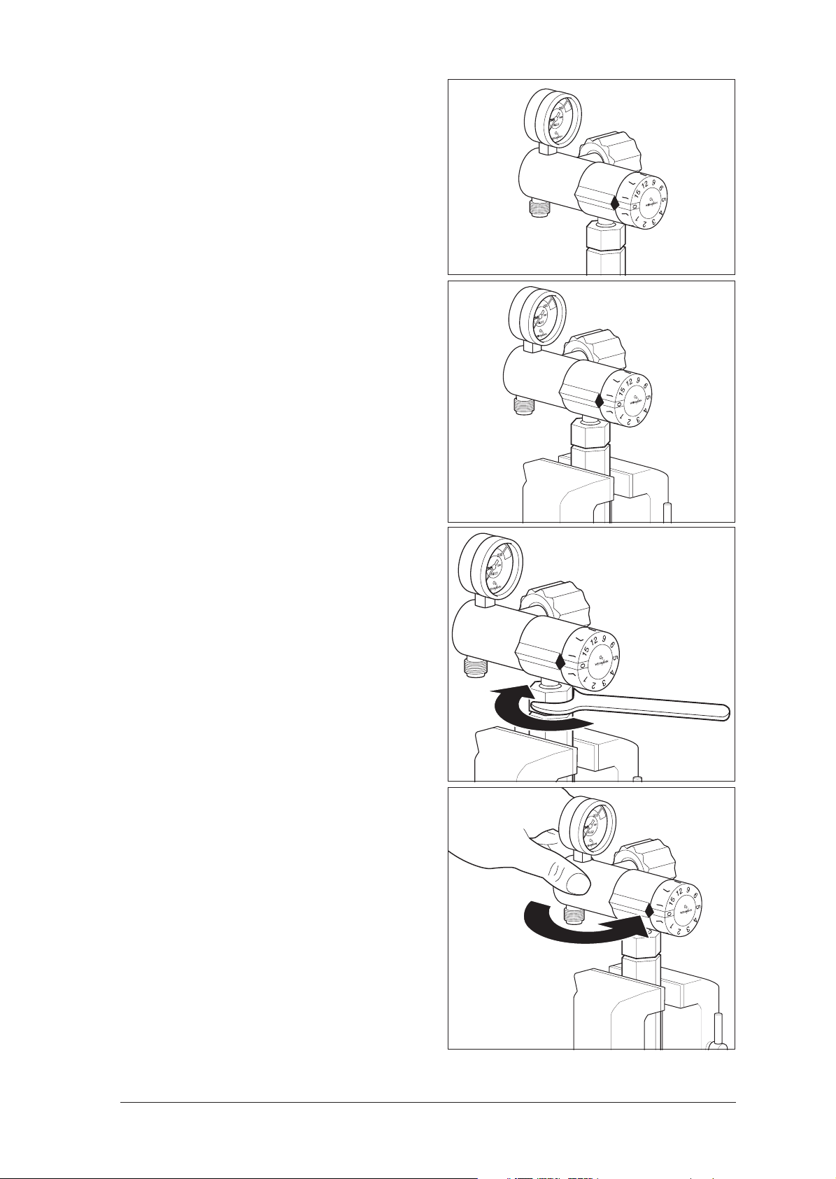
6.5 Replacing gage
Tools and material required:
• From tool set WM 15366:
– Counter tool with clamping handle WM 30035,
– Watchmaker’s screwdriver WM 30041 (cleaned with methylated spirit);
• Vise;
• Sealing ring 14 (WM 1145);
• Packing washer 0.5 mm 17 (WM 1145/35);
• Packing washer 0.8 mm
• Torque wrench 23 Nm – 1 Nm,
• Torque wrench 28 Nm + 2 Nm,
• Open-end wrench SW 12 or SW 14;
1. Clamp pressure reducer firmly in counter tool.
To do this, perform the following steps:
– Using a
cleaned screwdriver, carefully ease
sealing ring 14 out of groove in connector.
Be careful not to damage the groove at all.
– Clamp bottom part of counter tool firmly in
a vise.
– Place the top part of the counter tool on the
bottom part of the counter tool.
– Screw the connection nut onto the bottom
part of the counter tool.
– Tighten the connection nut using the top part
of the counter tool.
18 (WM 1145/36).
2
2. Loosen defective gage 1 or 8 with an openend wrench, then unscrew it by hand.
3. Carefully remove two packing washers 17 and
18 from threaded hole.
Take care not to damage sealing surface in body
of pressure reducer.
Ensure when taking out the packing washers
that no particles of dirt get into the bore of the
inside of the pressure reducer housing.
To guarantee the function of the pressure reducer, we recommend checking the inside of
the pressure reducer housing for any contamination before the final check. To do so, proceed in accordance with the relevant section
“Replacing piston on pressure reducer” (without changing the piston).
If you cannot remove the packing washers, do
not insert an additional packing washer
, but
send the pressure reducer to WEINMANN for
repair.
1 or 81718
Repair Information and Repair Instructions for pressure reducer OXYWAY and OXYTRON 27
Page 28

4. Of the two new packing washers, first insert
only the thicker 0.8 mm packing washer 18 in
the threaded hole.
5. Place open-end wrench insert in torque
wrench (23 Nm – 1 Nm).
6. Screw gage into pressure reducer by hand, then
tighten firmly with torque wrench.
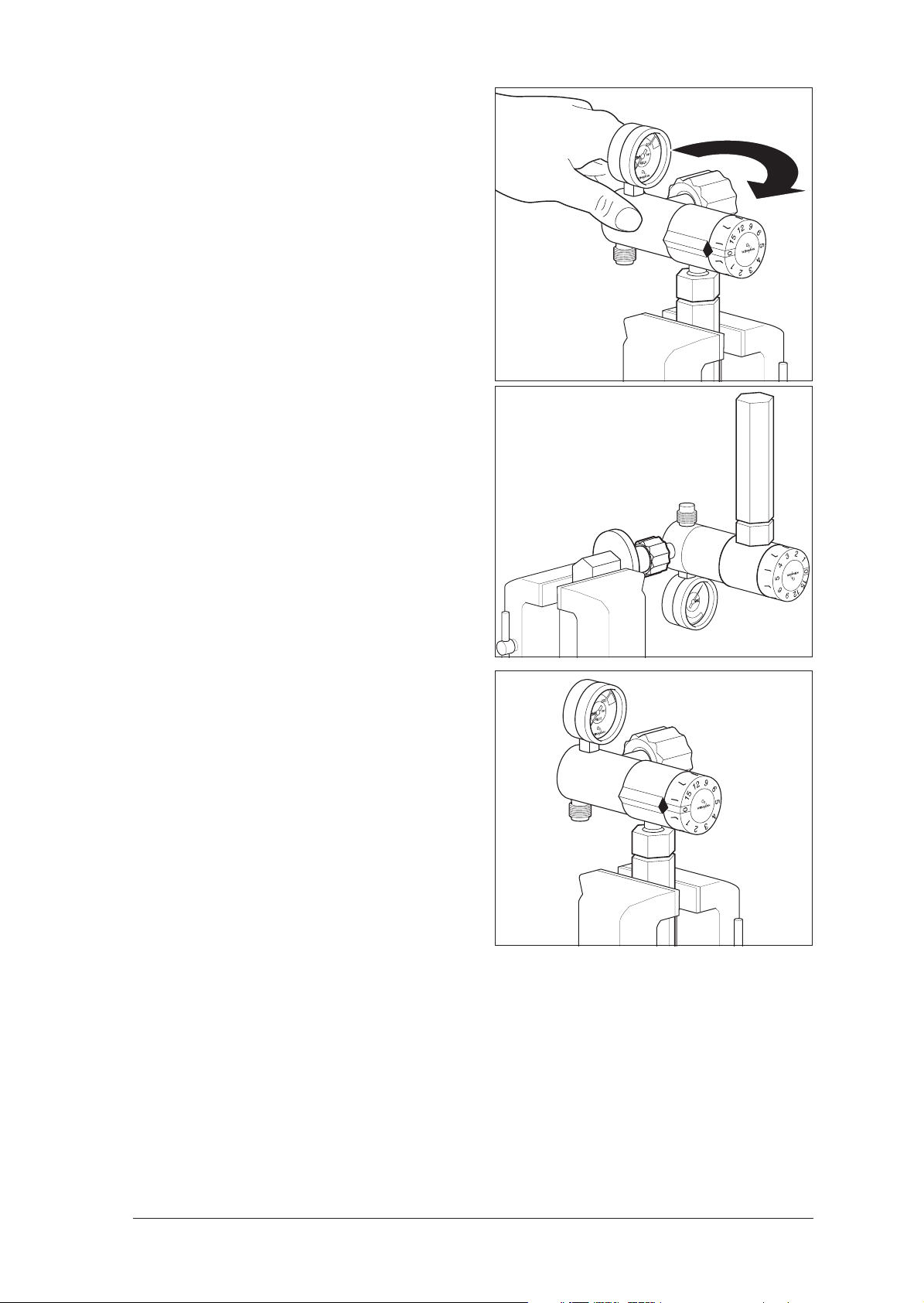
7. Check position of gage. If not correct,
– unscrew gage again,
– insert second packing washer 17 (0.5 or
0.8 mm) in threaded hole and
– tighten gage with torque wrench
(23 Nm – 1 Nm).
8. If position of gage in relation to body is still not
correct, turn gage to correct position using a
maximum torque of 28 Nm + 2 Nm.
9. Release pressure reducer from counter tool.
10. If necessary, clean groove in connector 2 with
dry cloth or cloth moistened with clean water.
17 (Do not use unless position of fitted gage is
incorrect. See step 7.)
11. Carefully press new sealing ring 14 into
groove. Do not use any tools.
12. Perform final check
(see “3. Final Check” on page 11).
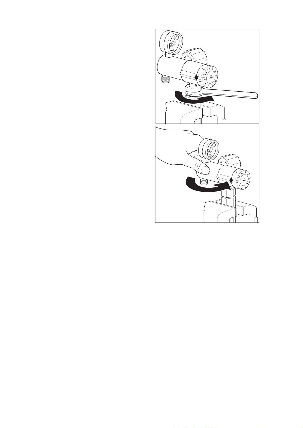
6.6 Replacing piston in pressure reducer FIX
(WM 30050, 30100, 30200, 30300, 30350)
Tools and material required:
• From tool set WM 15366:
– Cover clamping device WM 30036,
– Cover fitting device WM 30037,
– Counter crown WM 30038,
• Vise;
• Oxygen lubricant WM 14934.
• Torque wrench 8 Nm + 2 Nm,
• Open-end wrench insert SW 12;
1. Gently clamp cover clamping device in a vise.
2. Insert pressure reducer in cover clamping de-
vice.
3. Now clamp cover clamping device firmly in
the vise. This presses the two halves of the
clamping device together and holds the
pressure reducer in position.
4. Place counter crown over body. “A” on
counter crown must point toward connector 2.
5. Now turn body to left to loosen it, but do not
remove it yet
.
2
Counter crown
28 Repair Information and Repair Instructions for pressure reducer OXYWAY and OXYTRON
Page 29

6. Undo vise and remove pressure reducer.
7. Now carefully remove cover by hand.
Caution!
The piston spring is under strong compression.
Cover and spring could fly out at you.
8. Remove spring 21.
9. Remove any adjustment washers inserted by
the factory. Be sure to note their positions.
10. Remove faulty piston 16 from cover.
11. Blow out body and cover with oxygen.
Caution!
Make sure the oxygen you use for blowing out is
directed away from you in order to prevent any
accumulation of oxygen in your clothing.
When reassembling as described below, make
sure that all parts are clean and free from oil and
grease
.
21 16Washer
Body Cover
12. Apply a little oxygen lubricant to O-rings of
new piston 16, then carefully insert piston in
cover.
Important!
Take care not to damage O-rings.
13. Place body 4 in cover fitting device.
14. If adjustment washers were fitted, place them
in body. Be sure to place them in the correct
positions.
15. Insert spring 21 in body.
16. Carefully place cover on spring.
17. Now use cover fitting device to press cover
down onto body.
18. Maintaining compression, screw cover onto
body by hand (two to three turns are sufficient).
19. Remove pressure reducer from cover fitting
device.
O-rings
16
Cover
Cover
21
4
Repair Information and Repair Instructions for pressure reducer OXYWAY and OXYTRON 29
Page 30

20. Tighten cover by hand.
21. Clamp pressure reducer in cover clamping
device.
22. Place counter crown over body 4. “A” on
counter crown must point toward connector 2.
23. Screw body firmly onto cover with a torque
wrench (8 Nm + 2 Nm).
24. Undo vise and remove pressure reducer.
25. Perform final check
(see “3. Final Check” on page 11).
2
6.7 Replacing piston in pressure reducer FINE
(WM 30500, 30700, 30750)
Tools and material required:
• From tool set WM 15366:
– Cover clamping device WM 30036,
– Cover fitting device WM 30037,
– Counter crown WM 30038,
• Socket wrench 8 mm;
• Vise;
• Torque wrench 8 Nm + 2 Nm,
• Open-end wrench insert SW 12;
• Flat-bladed knife;
• Oxygen lubricant WM 14934.
Counter crown
1. Turn adjuster knob 9 to left until it meets the
stop.
2. Now remove cap 30 from adjuster knob by
sliding knife blade under cap and levering
cap off.
3. Hold adjuster knob tightly and unscrew nut 32
with a socket wrench.
4. Pull adjuster knob 9 off pressure reducer.
Take care not to lose driving plate 31 on inside of
adjuster knob.
309
32931
30 Repair Information and Repair Instructions for pressure reducer OXYWAY and OXYTRON
Page 31

5. Gently clamp cover clamping device in a vise.
6. Insert pressure reducer in cover clamping device.
7. Now clamp cover clamping device firmly in
vise. This presses the two halves of the cover
clamping device together and holds the pressure reducer in position.
8. Place counter crown over body. “A” on
counter crown must face toward connector 2.
9. Turn body to left to loosen it, but do not unscrew
completely yet
.
10. Undo vise and remove pressure reducer.
11. Carefully unscrew cover by hand.
Caution!
The piston spring is under strong compression.
Cover and spring could fly out at you.
12. Remove any adjustment washers inserted by
the factory. Be sure to note their positions.
13. Pull faulty piston 16 out of cover.
14. Remove small spring from piston.
15. Blow out body and cover with oxygen.
Caution!
Make sure the oxygen you use for blowing out is
directed away from you in order to prevent any
accumulation of oxygen in your clothing.
Counter crown
2
21 16WasherBody
Small spring
Cover
When reassembling as described below, make
sure that all parts are clean and free from oil and
grease
.
16. Put the small spring in the piston.
17. Push the piston carefully into the cover.
Important!
Take care not to damage the O-rings.
18. Place body 4 in cover fitting device.
19. If adjustment washers were fitted, place them
in body taking care to ensure correct
positions.
20. Insert spring 21 in body.
21. Carefully place cover on spring.
Small spring16Cover
O-rings
Washer
Repair Information and Repair Instructions for pressure reducer OXYWAY and OXYTRON 31
Page 32

22. Use cover fitting device to press cover down
onto body.
23. Maintaining compression, screw cover by
hand onto body (two to three turns is sufficient).
24. Remove pressure reducer from cover fitting
device.
25. Tighten cover by hand.
26. Clamp pressure reducer in cover clamping
device.
27. Place counter crown over body 4. “A” on
counter crown must face connector 2.
28. Screw body firmly to cover using a torque
wrench (8 Nm + 2 Nm).
29. Undo vise and remove pressure reducer.
Cover
21
4
Counter crown
2
30. Push driver plate
31 onto square part of
spindle 28.
31. Now push adjuster knob onto spindle
9 so that
driver plate 31 engages in recess in adjuster
knob.
32. Screw adjuster knob on firmly with new nut 32.
33. Push cap 30 onto adjuster knob.
34. Perform final check
(see “3. Final Check” on page 11).
32931
30
28
32 Repair Information and Repair Instructions for pressure reducer OXYWAY and OXYTRON
Page 33

6.8 Replacing piston in pressure reducer FAST
(WM 30600, 30800, 30850)
Tools and material required:
• From tool set WM 15366:
– Cover clamping device WM 30036,
– Cover fitting device WM 30037,
– Counter crown WM 30038,
– Screwdriver 3 mm WM 30043.;
– Screwdriver bit 9 mm WM 30039 (cleaned with methylated spirit),
– Watchmaker’s screwdriver WM 30041 (cleaned with methylated spirit),
• Vise;
• Torque wrench 8 Nm + 2 Nm,
• Open-end wrench insert SW 12;
• Flat-bladed knife;
• Oxygen lubricant WM 14934;
• plus for repairing pressure reducer WM 30850:
– Counter tool with clamping handle WM 30035 from tool set WM 15366,
• Torque wrench 25 Nm ± 1 Nm,
• Thread tap G 1/8,
• Brass wire brush,
• Sealing ring 14 (WM 1145);
• Loctite 245 WM 14920 (Never use a different Loctite product).
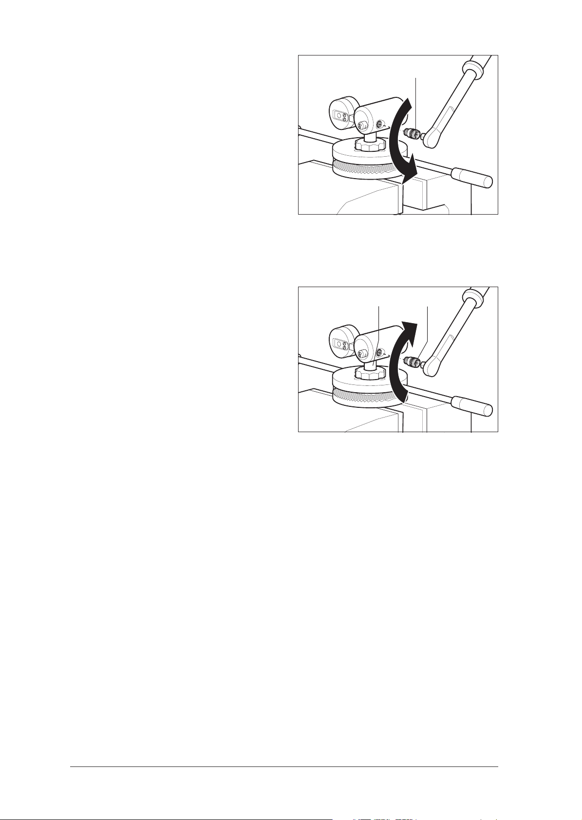
1. Turn index head 6 to position “0”.
2. Remove cap 51 from index head by sliding
knife blade under cap and levering off.
3. Hold index head tightly and unscrew the two
countersunk screws 52.
Take care not to change position of index head.
Otherwise you cannot be sure that the actual
flow values after reassembly will agree with
those shown on the index head.
4. Lever off loose part of index head 6.
5. Pull long part 50 of index head off body.
rear
oxygen
outlet
front
oxygen outlet
index head
front
oxygen
outlet
516
52650
Repair Information and Repair Instructions for pressure reducer OXYWAY and OXYTRON 33
Page 34

6. Gently clamp cover clamping device in a vise.
7. Slide the pressure reducer into the cover
clamping device so that the front oxygen outlet
fits into the opening of the cover clamping
device.
Please note!
Slide the pressure reducer into the cover clamping device until you clamp on to the cover only.
8. Now clamp cover clamping device firmly in
vise. This presses two halves of clamping
device together and holds pressure reducer in
position.
9. Place counter crown over body. “A” on
counter crown must face connector 2.
10. Now turn body to left to loosen it, but do not
completely unscrew it yet
.
11. Undo vise and remove pressure reducer.
12. Carefully unscrew cover by hand.
Caution!
The piston spring is under strong compression.
Cover and spring could fly out at you.
13. Remove spring 21 and any adjustment washers from body. Be sure to note their positions.
14. Pull faulty piston 16 out of cover.
15. Blow out body and cover with oxygen.
Counter crown
2
21 16
Cover
Body
Caution!
When blowing out with oxygen, take care that
the oxygen is directed away from you to prevent
any accumulation of oxygen in your clothing.
Cover assembly should not be loosened (dismantled) any farther, as this would cause changes in
the relevant flow rates and the alignment of the
two oxygen outlets in relation to each other.
When reassembling as described below, make
sure all parts are clean and free from oil and grease.
16. Carefully insert piston in cover.
Important!
Take care not to damage O-rings.
O-rings
16
Cover
Index heac
Cover
Front
oxygen outlet
index head
34 Repair Information and Repair Instructions for pressure reducer OXYWAY and OXYTRON
Page 35

17. Place body in cover fitting device.
18. If adjustment washers were fitted, place them
in body taking care to ensure correct positions.
19. Insert spring 21 in cover.
20. Carefully place cover onto body.
21. Use cover fitting device to press cover down
onto body.
22. Maintaining pressure, screw cover onto body
by hand (two to three turns are sufficient).
23. Remove pressure reducer from cover fitting
device.
24. Screw on cover hand tight.
25. Clamp pressure reducer in cover clamping
device.
26. Place counter crown over body. “A” on
counter crown must face connector 2.
27. Screw body firmly to cover using a torque
wrench (8 Nm + 2 Nm).
Caution!
The two oxygen outlets must be aligned.
Washer
Cover
21
4
Counter
crown
2
28. Undo vise and remove pressure reducer.
29. Push long part 50 of index head onto body.
30. Place index head 6 on pressure reducer.
Take care to fit it in correct position. Triangular
marker on long part of index head must then
point to “0”.
31. Screw on index head with two countersunk
screws 52.
32. Push cap 51 onto index head.
33. Perform final check
(see “3. Final Check” on page 11).
Front
oxygen outlet
Cover
Index head
52
51650
Repair Information and Repair Instructions for pressure reducer OXYWAY and OXYTRON 35
Page 36

6.9 Replacing piston in pressure reducer Fast II High Flow
(WM 31899)
Tools and material required:
• From tool set WM 15366:
– Cover clamping device WM 30036,
– Cover fitting device WM 30037,
– Counter crown WM 30038,
– Screwdriver 3 mm WM 30043.;
– Screwdriver bit 9 mm WM 30039 (cleaned with methylated spirit),
– Watchmaker’s screwdriver WM 30041 (cleaned with methylated spirit),
• Vise;
• Torque wrench 8 Nm + 2 Nm,
• Open-end wrench insert SW 12;
• Flat-bladed knife;
• Oxygen lubricant WM 14934;
• plus for repairing pressure reducer WM 31899:
– Counter tool with clamping handle WM 30035 from tool set WM 15366,
• Torque wrench 25 Nm ± 1 Nm,
• Thread tap G 1/8,
• Brass wire brush,
• Sealing ring 14 (WM 1145);
• Loctite 245 WM 14920 (Never use a different Loctite product).
1. Turn index head 6 to position “0”.
2. Remove cap 51 from index head by sliding
knife blade under cap and levering off.
3. Hold index head tightly and unscrew the two
countersunk screws 52.
Take care not to change position of index head.
Otherwise you cannot be sure that the actual
flow values after reassembly will agree with
those shown on the index head.
4. Lever off loose part of index head 6.
5. Pull long part 50 of index head off body.
rear
oxygen
outlet
front
oxygen outlet
index head
front
oxygen
outlet
516
52650
36 Repair Information and Repair Instructions for pressure reducer OXYWAY and OXYTRON
Page 37

6. Gently clamp cover clamping device in a vise.
7. Slide the pressure reducer into the cover
clamping device so that the front oxygen outlet
fits into the opening of the cover clamping device.
Please note!
Slide the pressure reducer into the cover clamping device until you clamp on to the cover only.
8. Now clamp cover clamping device firmly in
vise. This presses two halves of clamping
device together and holds pressure reducer in
position.
9. Place counter crown over body. “A” on
counter crown must face connector 2.
10. Now turn body to left to loosen it, but do not
completely unscrew it yet
.
11. Undo vise and remove pressure reducer.
12. Carefully unscrew cover by hand.
Caution!
The piston spring is under strong compression.
Cover and spring could fly out at you.
13. Remove spring 21 and any adjustment washers from body. Be sure to note their positions.
14. Pull faulty piston 16 out of cover.
15. Blow out body and cover with oxygen.
Caution!
When blowing out with oxygen, take care that
the oxygen is directed away from you to prevent
any accumulation of oxygen in your clothing.
Caution!
Cover assembly should not be loosened (dismantled) any farther, as this would cause changes in
the relevant flow rates and the alignment of the
two oxygen outlets in relation to each other.
2
Body
Counter crown
21 16
Cover
When reassembling as described below, make
sure all parts are
clean and free from oil and grease.
16. Carefully insert piston in cover.
Important!
Take care not to damage O-rings.
Repair Information and Repair Instructions for pressure reducer OXYWAY and OXYTRON 37
O-rings
16
Cover
Index heac
Cover
Front
oxygen outlet
index head
Page 38

17. Place body in cover fitting device.
18. If adjustment washers were fitted, place them
in body taking care to ensure correct positions.
19. Insert spring 21 in body.
20. Carefully place cover on spring.
21. Use cover fitting device to press cover down
onto body.
22. Maintaining pressure, screw cover onto body
by hand (two to three turns are sufficient).
23. Remove pressure reducer from cover fitting
device.
24. Screw on cover hand tight.
25. Clamp pressure reducer in cover clamping
device.
26. Place counter crown over body. “A” on
counter crown must face connector 2.
27. Screw body firmly to cover using a torque
wrench (8 Nm + 2 Nm).
Washer
Cover
21
4
Counter
crown
2
28. Undo vise and remove pressure reducer.
29. Push long part 50 of index head onto body.
30. Place index head 6 on pressure reducer.
Take care to fit it in correct position. Triangular
marker on long part of index head must then
point to “0”.
31. Screw on index head with two countersunk
screws 52.
32. Push cap 51 onto index head.
33. Perform final check
(see “3. Final Check” on page 11).
front
oxygen outlet
index headcap
52650
38 Repair Information and Repair Instructions for pressure reducer OXYWAY and OXYTRON
Page 39

6.10 Replacing index head / cover
• From tool set WM 15366:
– Cover clamping device WM 30036,
– Cover fitting device, WM 30037,
– Counter crown WM 30038,
– Special pliers for WM 30046,
– Counter tool:
UNF (from WM 14223 and WM 14224),
G 3/8 WM 22827 (from 15348 or WM 15349),
– Fitting aid,
– Allen (internal hexagon) key, 2 mm,
– Screwdriver 3 mm WM 30043;
– Screwdriver bit 9 mm WM 30039 (cleaned with methylated spirit),
– Watchmaker’s screwdriver WM 30041 (cleaned with methylated spirit),
• Vise;
• Torque wrench 8 Nm + 2 Nm;
• Open-end wrench insert SW 12;
• Flat-bladed knife;
• Oxygen lubricant WM 14934;
• plus for repairing pressure reducer WM 30850:
– Counter tool with clamping handle WM 30035 from tool set WM 15366,
• Torque wrench 25 Nm ± 1 Nm,
• Thread tap G 1/8,
• Brass wire brush,
• Sealing ring 14 (WM 1145);
• Loctite 245 WM 14920 (Never use a different Loctite product).
6.10.1 Dismantling adjuster knob
1. Set index head 6 to “0”.
2. Remove cap 51 from index head by sliding
knife blade under cap and levering off.
Rear
oxygen
outlet
Front
oxygen
outlet
516
Repair Information and Repair Instructions for pressure reducer OXYWAY and OXYTRON 39
Page 40

3. Hold index head firmly and unscrew the two
countersunk screws 52.
Take care not to change position of index head.
Otherwise you cannot be sure that the actual
flow values after reassembly will agree with
those shown on the index head.
Front
oxygen outlet
4. Lift off loose part of index head 6.
5. Pull long part 50 of index head off body.
6.10.2 Removing cover with index head from body
1. Gently clamp cover clamping device in a vise.
2. Insert pressure reducer in cover clamping
device so that front oxygen outlet fits into
opening in cover clamping device.
Caution!
Push pressure reducer into cover clamping device
only just far enough to clamp the cover itself.
3. Now clamp cover clamping device firmly in
vise. This presses the two halves of the cover
clamping device together and holds the
pressure reducer in position.
4. Place counter crown over body. “A” on
counter crown must face towards connector 2.
5. Turn body to left to loosen it, but do not unscrew
completely yet
.
6. Open vise and remove pressure reducer.
7. Carefully unscrew cover from index head.
Caution!
The piston spring is under strong compression.
Cover and spring could fly out at you.
8. Remove spring 21 and any adjustment
washers from body. Be sure to note their
positions.
A
2
Index head
21 16
52650
Counter crown
Front oxygen
outlet
Body
40 Repair Information and Repair Instructions for pressure reducer OXYWAY and OXYTRON
Cover
22
Page 41

6.10.3 Removing index head from cover
Caution!
Under the index disk are balls and springs which
are under compression. Perform the following
steps carefully, otherwise the springs and balls
could fly out at you.
1. Loosen grub screw 45 of index disk 43.
2. Carefully remove index disc 43, slide ring 44,
springs 42 and balls 41 from index head.
3. Push the locator for the orifice disk completely
out of the index head.
4. Clamp the cover about 20 mm down in the
cover clamping device.
5. Screw the special counter tool onto the oxygen
outlet and use the special pliers to remove the
union nut of the index head from the cover.
45
44
42
37
Cover
clamping
device
WM 30047
Special pliers
WM 30046
45
43
41
22
43
22
Counter tool
6.10.4 Assembling index head and cover
1. Take a new index head or cover, as
necessary.
2. Screw cover hand tight onto body.
3. Clamp pressure reducer in cover clamping
device.
4. Place counter crown over body. “A” on
counter crown must face towards connector.
5. Screw body onto cover using a torque wrench
(8 Nm +2 Nm).
22
A
Counter
crown
2
Repair Information and Repair Instructions for pressure reducer OXYWAY and OXYTRON 41
Page 42

6.10.5 Aligning oxygen outlet
1. Screw the empty index head onto the bottom
part of the housing.
2. Schrauben Sie die Anschlussmutter auf das
Konterwerkzeug.
3. Befestigen Sie das Konterwerkzeug an dem
Sauerstoffausgang.
4. Use the rubber-jawed pliers to slacken the
screwed connection on the index head.
5. Now use the special counter tool to turn the oxygen outlet into its final position. It should now
no longer be possible to turn the index head.
6. Both oxygen outlets are in line.
7. Release the special counter tools.
8. Unscrew the connection nut from the counter
tool.
9. Clamp the pressure reducer in the cover
clamping device.
10. Clamp the counter crown over the housing.
The A on the counter crown must point towards
the connection bolt.
11. Now release the housing by turning it
anticlockwise.
Counter tool
A
2
Special pliers
WM 30046
37
22
Counter
crown
6.10.6 Inserting orifice disk and fitting index disk
1. Place orifice holder 38 complete with orifice
disk 39 and slide disk 40 onto fitting aid and
push cover with index head onto it as far as
possible.
2. Remove pre-assembled cover from fitting aid.
40
39
38
42 Repair Information and Repair Instructions for pressure reducer OXYWAY and OXYTRON
Cover
clamping
device
Page 43

3. Align hole on inside of cover with hole in notch
pin.
4. Put the preassembled housing back on the
fitting aid. There must be no change in the
position of orifice holder in relation to cover.
hole on inside
of cover
hole in orifice disk
hole in notch pin
of orifice holder
5. Place slide disc 44 over projecting spindle of
orifice holder.
6. Insert springs 42 in corresponding holes and
place balls 41 on springs 42.
7. Place index disk 43 on balls 41 so that thread
of fixing screw is opposite oxygen outlet 35.
8. Use fitting aid to press index disk onto index
head. Secure index head with fixing screw.
9. Take assembled unit from fitting aid and check
position of holes in cover and notch pin.
44
45
37
36
43
41
42
35
22
40
39
38
6.10.7 Fitting index head with cover on body
1. Blow out body and cover with oxygen.
Caution!
When blowing out with oxygen, take care that
the oxygen is directed away from you to prevent
any accumulation of oxygen in your clothing.
When reassembling as described below, make
absolutely sure that all parts are clean and free from
oil and grease
2. Push the piston carefully into the cover.
Important
Take care not to damage O-rings.
3. Place body in cover fitting device.
4. If any adjustment washers were present, place
them in the body. Take care to fit in correct
position.
5. Insert spring
.
21 into cover.
O-rings
16
Cover
Index head
Cover
Front oxygen
outlet
Index head
Repair Information and Repair Instructions for pressure reducer OXYWAY and OXYTRON 43
Page 44

6. Carefully place cover onto body.
7. Now use cover fitting device to press cover
down onto body.
8. Maintaining the pressure, screw cover onto
body by hand (two to three turns is sufficient).
9. Remove pressure reducer from cover fitting
device.
10. Screw cover on firmly by hand.
11. Clamp pressure reducer in cover clamping
device.
12. Place counter crown over body. “A” on
counter crown must face towards connector 2.
13. Screw body onto cover using a torque wrench
(8 Nm + 2 Nm).
Caution!
The two oxygen outlets must be aligned.
14. Undo vise and remove pressure reducer.
Cover
21
4
Counter crown
2
6.10.8 Fitting adjuster knob
1. Push long part 50 of index head onto body.
2. Place index head
Take care to fit in correct position. Triangular
marker on long part of index head must then
point to “0”.
3. Screw on index head with two countersunk
screws 52.
4. Push cap
51 onto index head.
5. Perform final check.
(see “3. Final Check” on page 11).
6 on pressure reducer.
Front
oxygen outlet
Cover
Index head
52
51650
44 Repair Information and Repair Instructions for pressure reducer OXYWAY and OXYTRON
Page 45

6.11 Replacing index head/cover on Fast II High Flow pressure
reducer
• From tool set WM 15366:
– Cover clamping device WM 30036,
– Cover fitting device, WM 30037,
– Counter crown WM 30038,
– Special pliers for WM 30046,
– Counter tool UNF (from WM 14223 and WM 14224),
– Fitting aid,
– Allen (internal hexagon) key, 2 mm,
– Screwdriver 3 mm WM 30043;
– Screwdriver bit 9 mm WM 30039 (cleaned with methylated spirit),
– Watchmaker’s screwdriver WM 30041 (cleaned with methylated spirit),
• Vise;
• Torque wrench 8 Nm + 2 Nm;
• Open-end wrench insert SW 12;
• Flat-bladed knife;
• Oxygen lubricant WM 14934;
• plus for repairing pressure reducer WM 30850:
– Counter tool with clamping handle WM 30035 from tool set WM 15366,
• Torque wrench 25 Nm ± 1 Nm,
• Thread tap G 1/8,
• Brass wire brush,
• Sealing ring 14 (WM 1145);
• Loctite 245 WM 14920 (Never use a different Loctite product).
6.11.1 Dismantling adjuster knob
1. Set index head 6 to “0”.
2. Remove cap 51 from index head by sliding
knife blade under cap and levering off.
rear
oxygen
outlet
front
oxygen
outlet
516
Repair Information and Repair Instructions for pressure reducer OXYWAY and OXYTRON 45
Page 46

3. Hold index head firmly and unscrew the two
countersunk screws 52.
Take care not to change position of index head.
Otherwise you cannot be sure that the actual
flow values after reassembly will agree with
those shown on the index head.
front
oxygen outlet
4. Lift off loose part of index head 6.
5. Pull long part 50 of index head off body.
6.11.2 Removing cover with index head from body
1. Gently clamp cover clamping device in a vise.
2. Insert pressure reducer in cover clamping
device so that front oxygen outlet fits into
opening in cover clamping device.
Caution!
Push pressure reducer into cover clamping device
only just far enough to clamp the cover itself.
3. Now clamp cover clamping device firmly in
vise. This presses the two halves of the cover
clamping device together and holds the
pressure reducer in position.
4. Place counter crown over body 22. “A” on
counter crown must face towards connector 2.
5. Turn body 22 to left to loosen it, but do not
unscrew completely yet
.
6. Undo vise and remove pressure reducer.
7. Carefully unscrew cover from index head.
Caution!
The piston spring is under strong compression.
Cover and spring could fly out at you.
8. Remove spring 21 and any adjustment
washers from body. Be sure to note their
positions.
A
2
Body
52650
index headcap
Counter crown
22
21 16
Cover
6.11.3 Removing index head from cover
Caution!
Under the index disk are balls and springs which
are under compression. Perform the following
steps carefully, otherwise the springs and balls
could fly out at you.
46 Repair Information and Repair Instructions for pressure reducer OXYWAY and OXYTRON
45
44
42
37
43
41
22
Page 47

1. Loosen grub screw 45 of index disk 43.
2. Carefully remove index disc 43, slide ring 44,
springs 42 and balls 41 from index head.
3. Push orifice disk holder completely out of index
head.
4. Clamp cover about 20 mm deep in cover
clamping device.
Cover
clamping
device
WM 30047
45
43
22
5. Screw counter tool onto oxygen outlet and use
special pliers to remove union nut of index
Special pliers
WM 30046
head from cover.
6.11.4 Assembling and aligning index head and cover
1. Take a new index head or cover, as
necessary.
2. Screw cover hand tight onto body.
3. Clamp pressure reducer in cover clamping
device.
4. Place counter crown over body. “A” on
counter crown must face towards connector.
5. Screw body onto cover using a torque wrench
(8 Nm +2 Nm).
Special pliers
WM 30046
Counter tool UNF
37
22
Counter tool UNF
37
22
6. Place index head on cover so that oxygen
outlet is about 45 degrees before its end
position. Tighten union nut of index head by
hand.
7. Screw union nut of index head against cover
until you meet appreciable resistance.
8. Screw counter tool onto oxygen outlet.
9. Now use counter tool to turn oxygen outlet to
its end position. It should no longer be
possible to turn the index head out of position.
10. Remove counter tool from oxygen outlet.
Repair Information and Repair Instructions for pressure reducer OXYWAY and OXYTRON 47
Page 48

6.11.5 Inserting orifice disk and fitting index disk
1. Place orifice holder 38 complete with orifice
disk and notch pin onto fitting aid and push
cover with index head onto it as far as
possible.
2. Remove pre-assembled cover from fitting aid.
orifice disk
38
Cover
clamping
device
3. Align hole on inside of cover with hole in notch
pin.
4. Put the preassembled housing back on the
fitting aid. There must be no change in the
position of orifice holder in relation to cover.
5. Place slide disc 44 over projecting spindle of
orifice holder.
6. Insert springs 42 in corresponding holes and
place balls 41 on springs 42.
7. Place index disk
43 on balls 41 so that thread
of fixing screw is opposite oxygen outlet 35.
8. Use fitting aid to press index disk onto index
head. Secure index head with fixing screw.
9. Take assembled unit from fitting aid and check
position of holes in cover and notch pin.
hole on inside
of cover
hole in orifice disk
hole in notch pin
of orifice holder
45
44
37
36
43
41
42
35
22
48 Repair Information and Repair Instructions for pressure reducer OXYWAY and OXYTRON
40
39
38
Page 49

6.11.6 Fitting index head with cover on body
1. Blow out body and cover with oxygen.
Caution!
When blowing out with oxygen, take care that
the oxygen is directed away from you to prevent
any accumulation of oxygen in your clothing.
When reassembling as described below, make
absolutely sure that all parts are clean and free from
oil and grease
.
2. Carefully insert piston in cover.
Important
Take care not to damage O-rings.
3. Place body 4 in cover fitting device.
4. If any adjustment washers were present, place
them in the body. Take care to fit in correct
position.
5. Insert spring 21 in body.
6. Carefully place cover on spring.
7. Now use cover fitting device to press cover
down onto body.
8. Maintaining the pressure, screw cover onto
body by hand (two to three turns is sufficient).
9. Remove pressure reducer from cover fitting
device.
10. Screw cover on firmly by hand.
O-rings
Disk
16
Cover
Index head
Cover
Front oxygen
outlet
Index head
11. Clamp pressure reducer in cover clamping
device.
12. Place counter crown over body 4. “A” on
counter crown must face towards connector 2.
13. Screw body onto cover using a torque wrench
(8 Nm + 2 Nm).
Caution!
The two oxygen outlets must be aligned.
14. Undo vise and remove pressure reducer.
Repair Information and Repair Instructions for pressure reducer OXYWAY and OXYTRON 49
Cover
21
4
Counter crown
2
22
Page 50

6.11.7 Fitting adjuster knob
1. Push long part 50 of index head onto body.
2. Place index head 6 on pressure reducer.
Take care to fit in correct position. Triangular
marker on long part of index head must then
point to “0”.
Front
oxygen outlet
3. Screw on index head with two countersunk
screws 52.
4. Push cap 51 onto index head.
5. Perform final check.
Cover
Index head
(see “3. Final Check” on page 11).
6.12 Replacing Connector and Sinter Filter
Tools and material required:
• From tool set WM 15366:
– Counter tool with clamping handle WM 30035,
– Counter crown WM 30038,
– Watchmaker’s screwdriver WM 30041 (cleaned with methylated spirit);
• Vise;
• Torque wrench 55 Nm ± 1 Nm,
• Open-end wrench insert SW 12;
• Oxygen lubricant WM 14934;
• Sealing ring 14 (WM 1145);
• Sinter filter 19 (WM 6619);
• Filter screw 12 (WM 30905).
52
51650
1. Clamp pressure reducer firmly in counter tool.
Proceed as follows:
– Using cleaned screwdriver, carefully ease
sealing ring 14 out of groove in connector.
Take care not to damage groove in any way.
– Clamp bottom part of counter tool in a vise.
– Place the top part of the counter tool on the
bottom part of the counter tool.
– Screw connection nut 2 onto the bottom
part of the counter tool.
– Tighten connection nut 2 using the top part
of the counter tool.
50 Repair Information and Repair Instructions for pressure reducer OXYWAY and OXYTRON
2
15
Page 51

2. Place counter crown over body 4. “A” on
counter crown must face connector 2.
3. Place torque wrench (with open-end wrench
insert) lengthwise on square end of counter
crown.
4. Loosen body by unscrewing to left, then remove completely by hand.
5. Remove connector 2 from counter tool.
6. Check connection nut 15 and new
connector 2 for defects (e.g. thread, chrome
plating, sealing surface).
Do not refit faulty parts.
7. If necessary clean groove in connector 2 with
dry cloth or cloth moistened with clean water.
8. Fasten connector 2 firmly in counter tool with
connection nut 15.
9. Blow out connector with oxygen.
Caution!
When blowing out, make sure oxygen is directed
away from you to prevent any accumulation of
oxygen in your clothing.
10. Insert a new sinter filter 19 in connector.
Do not on any account use Loctite or other thread
sealants.
19
11. Screw body onto connector by hand.
12. Place counter crown over body 4. “A” on
counter crown must face connector 2.
13. Using torque wrench (55 Nm ± 1 Nm),
tighten body securely on connector.
14. Release pressure reducer from counter tool.
15. Insert new filter screw 12 in connector (see
“6.3 Replacing filter screw” on page 21).
16. Carefully press new sealing ring 14 into
cleaned groove. Do not use tools.
17. Perform final check
(see “3. Final Check” on page 11).
Repair Information and Repair Instructions for pressure reducer OXYWAY and OXYTRON 51
Page 52

6.13 Changing connector and sinter filter in OXYTRON pressure
reducer
Tools and material required:
• From tool set WM 15366:
– Bottom part of counter tool WM 30035,
– Counter crown WM 30038,
– Watchmaker’s screwdriver WM 30041 (cleaned with methylated spirit);
– Single-end wrench SW 19 WM 30040 (cleaned with methylated spirit).
• Vise;
• Torque wrench 55 Nm ± 1 Nm,
• Torque wrench 10 Nm + 2 Nm,
• Open-end wrench insert SW 12;
• Open-end wrench SW 30;
• Oxygen lubricant WM 14934;
• Sealing ring
• Sinter filter
• Filter screw 12 (WM 30905).
1. Clamp pressure reducer firmly in counter tool.
Proceed as follows:
– Using cleaned screwdriver, carefully ease
sealing ring 14 out of groove in connector.
Take care not to damage groove in any way.
– Clamp bottom part of counter tool firmly in
a vise.
– Insert connector
– Use open-end wrench SW 30 to tighten
connection nut
14 (WM 1145);
19 (WM 6619);
52
2
15
2 in stub of bottom part.
15.
2. Using the cleaned single-end wrench SW 19,
turn second stage 52 to left and unscrew it (see
“6.14 Replacing second stage of OXYTRON
pressure reducer (WM 30150)” on
page 54).
3. Place counter crown over body 4. “A” on
counter crown must face connector 2.
4. Place torque wrench (with open-end wrench
insert) lengthwise on square end of counter
crown.
5. Loosen body by turning to left, then remove by
hand.
6. Release connector 2 from counter tool.
7. Check connection nut 15 and new
connector 2 for defects (e.g. thread, chrome
plating, sealing surface).
Do not refit faulty parts.
8. If necessary clean groove in connector 2 with
dry cloth or cloth moistened with clean water.
52 Repair Information and Repair Instructions for pressure reducer OXYWAY and OXYTRON
Page 53

9. Using open-end wrench SW 30, fix new
connector 2 firmly in bottom part of counter
tool with connection nut 15.
10. Blow out connector with oxygen.
Caution!
When blowing out connector, make sure that
oxygen is directed away from you to prevent any
accumulation of oxygen in your clothing.
11. Insert a new sinter filter 19 in connector.
Do not on any account use Loctite or other thread
sealants.
12. Screw body onto connector by hand.
13. Place counter crown over body 4. “A” on
counter crown must face connector 2.
14. Use torque wrench (55 Nm ± 1 Nm) to screw
body firmly onto connector.
15. Fit new second stage:
– Remove adhesive residues from threads.
Use a brass wire brush for the external
thread and, if necessary, a thread tap
G 1/8 for the internal thread.
Caution:
When cleaning threads, make sure no dirt
enters body.
– Pick up second stage 52.
Caution:
Second stage 52 must be clean and free from oil
and grease.
– Apply a little Loctite 245 to thread, except
for the first two turns.
First two turns are left free so no Loctite can get
into the body.
– Screw second stage 52 into the pressure
reducer by hand.
– Use screwdriver bit and torque wrench
(10 Nm + 2 Nm) to tighten second
stage 52.
16. Release pressure reducer from counter tool.
17. Insert a new filter screw 12 in connector (see “6.3
Replacing filter screw” on page 21).
18. Carefully press new sealing ring 14 into groove. Do
not use tools.
19
2
15
52
19. Perform final check
(see “3. Final Check” on page 11).
Repair Information and Repair Instructions for pressure reducer OXYWAY and OXYTRON 53
Page 54

6.14 Replacing second stage of OXYTRON pressure reducer
(WM 30150)
Tools and material required:
• From tool set WM 15366:
– Counter tool with clamping handle WM 30035;
– Screwdriver bit 9 mm WM 30039 (cleaned with methylated spirit);
– Watchmaker’s screwdriver WM 30041 (cleaned with methylated spirit);
– Single-end wrench SW 19 WM 30040.
• Vise;
• Torque wrench 10 Nm + 2 Nm
• Open-end wrench SW 30
• Sealing ring
• Loctite 245 WM 14920 (never use a different Loctite product).
Note:
Position of set screw in outlet from second stage must not be changed, as this would change the flow rate.
1. Clamp pressure reducer firmly in counter tool.
Proceed as follows:
– Using cleaned screwdriver, carefully ease
sealing ring 14 out of groove in connector.
Take care not to damage groove in any way.
– Clamp bottom part of counter tool firmly in
a vise.
– Insert connector 2 in stub of bottom part.
– Use open-end wrench SW 30 to screw
connection nut 15 tight.
14 (WM 1145);
52
2
15
2. Using cleaned single-end wrench, turn faulty
second stage 52 to left and unscrew.
3. Fit new second stage:
– Remove adhesive residues from screw
threads. Use screw tap G 1/8 for internal
thread.
Caution:
When cleaning screw threads, do not let any
dirt enter the body.
– Pick up a new second stage 52.
Caution:
Second stage 52 must be clean and free from
oil and grease.
– Apply a little Loctite 245 to screw thread,
except for first two turns.
First two turns must be left free of Loctite so no
Loctite can get inside body.
52
54 Repair Information and Repair Instructions for pressure reducer OXYWAY and OXYTRON
Page 55

– Screw second stage 52 into pressure
reducer by hand.
– Using screwdriver bit 9 mm and torque
wrench (10 Nm + 2 Nm), screw second
stage 52 up tight.
4. Release pressure reducer from counter tool.
5. If necessary, clean groove in connector 2 with
dry cloth or cloth moistened with clean water.
6. Carefully press new sealing ring 14 into
groove. Do not use tools.
7. Perform final check
(see “3. Final Check” on page 11).
52
6.15 Replacing first-stage piston in OXYTRON pressure reducer
(WM 30150)
Tools and material required:
• From tool set WM 15366:
– Counter tool with clamping handle WM 30035,
– Screwdriver bit 9 mm WM 30039 (cleaned with methylated spirit);
– Watchmaker’s screwdriver WM 30041 (cleaned with methylated spirit);
– Single-end wrench SW 19 WM 30040 (cleaned with methylated spirit).
• Vise;
• Torque wrench 25 Nm ± 1 Nm
• Open-end wrench SW 30
• Sealing ring 14 (WM 1145);
• Loctite 245 WM 14920 (Never use a different Loctite product).
Note:
Position of set screw in second-stage outlet must not be altered, as this would change the flow rate.
1. Unscrew second stage (see “6.14 Replacing
second stage of OXYTRON pressure reducer
(WM 30150)” on page 54).
2. Replace piston (see “6.6 Replacing piston in
pressure reducer FIX (WM 30050, 30100,
30200, 30300, 30350)” on page 28).
3. Screw second stage on again (see “6.14 Replacing second stage of OXYTRON
pressure reducer (WM 30150)” on
page 54).
Repair Information and Repair Instructions for pressure reducer OXYWAY and OXYTRON 55
Page 56

6.16 Replacing second-stage piston in OXYTRON pressure reducer
(WM 30150)
Tools and material required:
• From tool set WM 15366:
– Counter tool with clamping handle WM 30035,
– Screwdriver bit 9 mm WM 30039 (cleaned with methylated spirit);
– Watchmaker’s screwdriver WM 30041 (cleaned with methylated spirit);
– Single-end wrench SW 19 WM 30040 (cleaned with methylated spirit).
• Vise;
• Oxygen lubricant WM 14934.
• Torque wrench 10 Nm + 2 Nm
• Sealing ring
• Loctite 245 WM 14920 (Never use a different Loctite product).
Note:
Position of set screw in second-stage outlet must not be altered, as this would change the flow rate.
1. Clamp pressure reducer firmly in counter tool.
Proceed as follows:
– Using cleaned screwdriver, carefully ease
sealing ring 14 out of groove in connector.
Take care not to damage groove in any way.
– Clamp bottom part of counter tool in a vise.
– Screw up connection nut by hand.
14 (WM 1145);
2. Open cover 54 of second stage by holding
body 53 with special open-end wrench
SW 19 and loosening cover 54 with 9 mm
screwdriver bit.
3. Slowly unscrew cover 54 by hand.
Note:
Piston spring is under compression!
4. Remove spring 55.
5. Remove faulty piston 56 from cover.
Note:
When reassembling as described below, make sure
all parts are clean and absolutely free from grease.
Sliding surface of O-ring on inside of cover 54 must
not be scored or scratched.
53
55
53 54
54
56
56 Repair Information and Repair Instructions for pressure reducer OXYWAY and OXYTRON
Page 57

6. Apply a little oxygen lubricant to O-ring and
carefully insert new piston 56 in cover.
Caution:
Do this very carefully. New O-rings must not be
damaged during insertion.
7. Place spring 55 on piston.
8. Screw cover 54 onto body 53 by hand.
9. Hold body with special open-end wrench
SW 19. Then use 9 mm screwdriver bit and
torque wrench (10 Nm + 2) to tighten cover.
10. Release pressure reducer from counter tool
with open-end wrench SW 30.
11. If necessary clean groove in connector 2 with
dry cloth or cloth moistened with clean water.
12. Carefully press new sealing ring 14 into
groove. Do not use tools.
13. Perform final check
(see “3. Final Check” on page 11).
Repair Information and Repair Instructions for pressure reducer OXYWAY and OXYTRON 57
Page 58

7. Repair Information and Repair Instructions for
flowmeter OXYWAY Click
7.1 General
• Observe the safety information on page 4 of the
Operating Instructions for OXYWAY Click.
• Caution:
Spontaneous explosive reactions can occur if
compressed oxygen comes into contact with
flammable substances (grease, oil, alcohol etc.)!
To prevent explosion risks, make sure your
hands, tools and workplace are absolutely
free from oil and grease during the repair
work.
For this reason you should always wash your
hands before starting work.
• Any operations on the appliance presuppose
detailed knowledge and observance of the
Operating Instructions and the Service and
Repair Instructions.
7.2 Replacing index head / cover
• You should only carry out repairs described in
these Service and Repair Instructions. Otherwise proper functioning of OXYWAY Click
cannot be guaranteed.
• Be sure to perform a final check after every
repair (see “3. Final Check” on page 11).
• If you replace components or individual parts,
always use genuine WEINMANN parts only.
• Certain parts must be screwed up using a
torque wrench. To ensure compliance with the
specified torque, check your torque wrench
regularly for torque compliance (control of inspection, measuring and test equipment).
• Note:
The item numbers in the following text are the
same as the item numbers in the Replacement
Parts List on page 64 and the overview on
page 4.
• From tool set WM 15366:
– Cover clamping device WM 30036,
– Counter tool:
G 3/8 WM 22827 (from WM 15348 or WM 15349),
UNF (from WM 14223 or WM 14224)
– Fitting aid,
– Allen (internal hexagon) key, 2 mm,
– Screwdriver 3 mm WM 30043;
• Vise;
• Torque wrench 16 Nm + 2 Nm;
• Flat-bladed knife;
• Oxygen lubricant WM 14934;
58 Repair Information and Repair Instructions for flowmeter OXYWAY Click
Page 59

7.2.1 Dismantling adjuster knob
1. Set index head 6 to “0”.
2. Remove cap 51 from index head by sliding
knife blade under cap and levering off.
3. Hold index head firmly and unscrew the two
countersunk screws 52.
Take care not to change position of index head.
Otherwise you cannot be sure that the actual
flow values after reassembly will agree with
those shown on the index head.
Oxygen outlet
4. Lift off loose part of index head 6.
5. Pull long part 50 of index head off body.
7.2.2 Removing cover with index head from body
1. Gently clamp cover clamping device in a vise.
2. Now clamp cover clamping device firmly in
vise. This presses the two halves of the cover
clamping device together and holds the
flowmeter in position.
Oxygen
outlet
Index head
516
52650
Counter tool
22
3. Now loosen body (do not unscrew completely
yet!
) by turning it anti-clockwise.
4. Undo vise and remove flowmeter.
5. Now slowly unscrew the body from the index
head.
Repair Information and Repair Instructions for flowmeter OXYWAY Click 59
Oxygen outlet
Cover
Page 60

7.2.3 Removing index head
Caution!
Under the index disk are balls and springs which
are under compression. Perform the following
steps carefully, otherwise the springs and balls
could fly out at you.
1. Loosen grub screw 45 of index disk 43.
2. Carefully remove index disc 43, slide ring 44,
springs 42 and balls 41 from index head.
3. Push orifice disk holder completely out of index
head.
4. Clamp cover about 20 mm deep in cover
clamping device.
5. Screw counter tool onto oxygen outlet and use
special pliers to remove union nut of index
head from cover.
Cover
clamping
device
WM 30047
45
44
42
37
43
41
36
22
43
22
Counter tool
22
7.2.4 Assembling index head and cover
1. Take a new index head or cover, as
necessary.
2. Tighten up the body hand-tight on the cover for
the central gas supply system.
3. Clamp flowmeter in cover clamping device.
4. Screw the body into the central gas supply
cover using a torque wrench (8 Nm +2 Nm).
5. Place index head on cover so that oxygen
outlet is about 45 degrees before its end
position. Tighten union nut of index head by
hand.
Counter tool
22
60 Repair Information and Repair Instructions for flowmeter OXYWAY Click
Page 61

6. Screw union nut of index head against cover
until you meet appreciable resistance.
7. Screw special counter tool onto oxygen outlet.
8. Now use special counter tool to turn oxygen
outlet to its end position. It should no longer be
possible to turn the index head out of position.
9. Remove special counter tool from oxygen
outlet.
7.2.5 Inserting orifice disk and fitting index disk
1. Use cover clamping device to remove index
head with cover from body.
2. Place orifice holder complete with orifice disk
and notch pin onto fitting aid and push cover
with index head onto it as far as possible.
3. Remove pre-assembled cover from fitting aid.
Counter tool
Special pliers
22
38
4. Align hole on inside of cover with hole in notch
pin.
5. Place pre-assembled cover on fitting aid
again. There must be no change in the
position of orifice holder in relation to cover.
6. Place slide ring over projecting spindle of
orifice holder.
7. Insert springs in corresponding holes and
place balls on springs.
Repair Information and Repair Instructions for flowmeter OXYWAY Click 61
Cover
clamping
device
hole on inside
of cover
hole in orifice disk
hole in notch pin
of orifice holder
Page 62

8. Place index disk on balls so that thread of
fixing screw is opposite oxygen outlet.
9. Use fitting aid to press index disk onto index
head. Secure index head with fixing screw.
10. Take assembled unit from fitting aid and check
position of holes in cover and to notch pin.
44
45
37
36
43
41
42
35
22
40
39
38
7.2.6 Assembling index head and housing
1. Clamp the cover clamping device gently in a
vise.
2. Now clamp the cover clamping device in the
vise. This presses the two halves of the clamping device firmly together and holds the cover
of the flowmeter in position.
3. Screw the housing on the central gas supply
system cover tight.
7.2.7 Fitting adjuster knob
1. Push long part 50 of index head onto body.
2. Place index head
Take care to fit in correct position. Triangular
marker on long part of index head must then
point to “0”.
3. Screw on index head with two countersunk
screws 52.
4. Push cap
51 onto index head.
5. Perform final check.
(see “3. Final Check” on page 11).
6 on pressure reducer.
Special pliers
Oxygen outlet
Cover
Counter tool
22
52650
51
Index head
62 Repair Information and Repair Instructions for flowmeter OXYWAY Click
Page 63

7.3 Changing filter screw
Tools required:
• From tool set WM 15366:
– Allen wrench 4 mm WM 30042 (cleaned with methylated spirit).
1. Release the index head and the body of the
flowmeter from the central gas supply system
cover as described in “7.2 Replacing index
head / cover” on page 58.
The filter screw is located on the inside of the central gas supply system cover (see drawing).
2. If necessary, clean the hexagon socket of filter
screw 12 using a small screwdriver.
3. Loosen filter screw
yet.
4. So that no dirt can fall into the flowmeter, hold
the
central gas supply system cover with the con-
nector pointing down. In this position, unscrew
filter screw 12 completely.
5. Screw a new filter screw 12 firmly into the cen-
tral gas supply system cover
12, but do not unscrew it
6. Refit the index head and cover as described in
“7.2 Replacing index head / cover” on
page 58.
7. Perform a final check. Enter the filter screw
change and date in the service record.
.
central gas
supply system
cover
12
7.4 Replace central gas supply system plug connection
Tools required:
• Cover clamping device WM 30036,
• Open-end wrench SW 17
• Loctite WM 14901
1. Undo the index head as described in “7.2 Replacing index head / cover” on page 58.
2. Clamp the flowmeter in the cover clamp so
that only the cover is clamped.
3. Release the old plug connection and take it off
the body.
4. Remove the old seal and put in a new one (unless it is a Swedish AGA connector).
5. Wet the thread (leave first two turns) of the
plug connector with a little Loctite 601.
6. Insert the new plug connector in the body and
tighten it up with an open-ended wrench.
Ensure that the plug connector is correctly lined up.
Two of the six sides (see drawing) must be flush with
the O
outlet. This ensures that the O2 outlet of the
2
flowmeter points vertically downwards when it is
connected to the central gas supply system.
7. Perform a final check (see “3. Final Check” on
page 11).
Repair Information and Repair Instructions for flowmeter OXYWAY Click 63
Page 64

8. Replacement Parts
Note:
The item numbers in the following tables are the same as the numbers in the text of these Service and Repair
Instructions.
8.1 Information about conformity with standards
Up to serial number 0849999, OXYWAY
pressure reducers meet standard EN 738-1.
From serial number 0850000, OXYWAY
pressure reducers meet standard EN ISO 105241:2006.
In the course of adapting the products to standard
EN ISO 10524-1:2006, it was not possible to
design all components to be downward-compatible. Parts which are not downward-compatible are
available for both device statuses and are marked
accordingly in the replacement parts lists (see “8.
Ersatzteile” on page 69) of these instructions.
Caution!
Malfunction as a result of unclear device status.
If replacement parts which are not downward-compatible are used in the wrong pressure reducers,
connected devices will malfunction.
• Fit replacement parts which are not downward-compatible only in accordance with the
pressure reducer serial numbers quoted.
• Do not convert pressure reducers up to
SN 0849999 “to suit the new standard”.
64 Replacement Parts
Page 65

8.2 Replacement parts list for all pressure reducers
1
17
18
13 Plate, service
19
15
14
12
20
Plate, filter screw change
16
Item No. Description Order No.
Maintenance kit WM 15458
1 Contents gage 0 – 315 bar WM 30914
12 Filter screw WM 30905
13 Plate, service, 4 years WM 75341
14 Sealing ring, O-ring 12.3 x 2.4 WM 1145
Connection nut for all connectors except WM 30150 (DE) (see
15
“8.10 Additional replacement parts 2nd stage OXYTRON
WM 30150” on page 73 and “8.11 Connections for pressure
WM 1144/16
reducer” on page 74)
16 Piston, complete WM 30910
17 Sealing washer 4 x 8 x 0.5 (for gage) WM 1145/35
18 Sealing washer 4 x 8 x 0.8 (for gage) WM 1145/36
19 Sinter filter WM 6619
20 Plate, filter screw change WM 0495
Gage cap WM 30960
Safety tag WM 16211
Set of replacement seals WM 1148
Oxygen lubricant WM 14934
The instructions for use for the devices are available on the Internet at www.weinmann.de or contact
WEINMANN.
Replacement Parts 65
Page 66

8.3 Additional replacement parts for WM 30050
7
23
2
24
21 22
Item No. Description Order No.
2 Connector see chapter 8.11
Thread connection, complete (oxygen outlet)
7
21 Spring for piston WM 30924
22 Cover (body cover) WM 30922
23 Screw plug G 1/8 WM 1519
24 Cap WM 30993
– Threaded connection up to SN 0849999
– Threaded connection from SN 0850000
WM 30927
WM 30002
66 Replacement Parts
Page 67

8.4 Additional replacement parts for WM 30100, 30150,
30200, 30300
7
Item No. Description Order No.
2 Connector see chapter 8.11
Threaded connection, complete (oxygen outlet)
– WM 30100 up to SN 0849999
7
21 Spring for piston WM 30924
22 Cover (body cover) WM 30922
– WM 30100 from SN 0850000
– WM 30150
– WM 30200, 30300
2
21 22
WM 30926
WM 30005
WM 30904
WM 30936
Replacement Parts 67
Page 68

8.5 Additional replacement parts for WM 30500, 30700, 30750
26 27 28
21
25
7
8
30
2
22
29
32
9
31
Item No. Description Item No.
2 Connector see chapter 8.11
Threaded connection, complete (oxygen outlet) up to SN 0849999:
– Threaded connection, complete 3 – 15 l/min for WM 30500
– Threaded connection, complete 1.5 – 8 l/min for WM 30700
– Threaded connection, complete 0.5 – 3 l/min für WM 30750
7
Threaded connection, complete (oxygen outlet) from SN 0850000:
– Threaded connection, complete 3 – 15 l/min for WM 30500
– Threaded connection, complete 1.5 – 8 l/min for WM 30700
– Threaded connection, complete 0.5 – 3 l/min für WM 30750
WM 30946
WM 30966
WM 30969
WM 31119
WM 31120
WM 31121
Flow gage for devices up to SN 0849999:
– Flow gage 3 – 15 l/min for WM 30500
– Flow gage 1.5 – 8 l/min for WM 30700
– Flow gage 0.5 – 3 l/min for WM 30750
8
Flow gage for devices from SN 0850000:
– Flow gage 3 – 15 l/min for WM 30500
– Flow gage 1.5 – 8 l/min for WM 30700
– Flow gage 0.5 – 3 l/min for WM 30750
9 Rotary knob (adjuster knob) WM 30949
21 Spring for piston WM 30954
22 Cover (body cover) WM 30952
25 Washer 18 x 27.2 x 2 WM 30944
26 Spring for lifting pin WM 30959
WM 30961
WM 30962
WM 30963
WM 31112
WM 31113
WM 31114
– Lifting pin (up to SN 0849999)
27
– Lifting pin, long (from SN 0850000)
– Spindle (up to SN 0849999)
28
– Spindle (from SN 0850000)
29 O-ring 11.91 x 2.62 WM 1145/96
30 Cap for adjuster knob 9, printed WM 30950
31 Driver plate WM 3812
32 Hexagonal nut DIN 985 – M5 – 8 ST–GalZn WM 51446
68 Replacement Parts
WM 30956
WM 31102
WM 30957
WM 31103
Page 69

8.6 Additional replacement parts for WM 30800, 30850
46
50 43
2
51
37
40
40
6
42
41
52
33
7
21
34 3536 45
22
39
474844
Item No. Description Order No.
2 Connector see chapter 8.11
6 Rotary knob (index head), printed WM 30985
7 Threaded connection, complete (oxygen outlet) WM 30999
21 Spring for piston WM 30924
22 Cover (body cover) WM 30972
33 Sealing washer 7 x 14 x 2 WM 1145/31
34 Union nut (for threaded connection 7) WM 1232
Index head, complete, comprising:
35
36
37
38
39
40
41
42
43
44
45
46 O-ring 20.35 x 1.78 WM 1145/97
47 O-ring 7.65 x 1.78 WM 1145/102
Threaded connection, complete (oxygen outlet):
– Threaded connection up to SN 0849999
– Threaded connection from SN 0850000
– Union nut
– Index head
– Orifice disk holder, complete
– Orifice disk 0-15 l/min
– Slide disk
– Ball
– Spring
– Index washer
– Slide disk 6 x 12 x 0.5
– Set screw DIN EN ISO 4029 M4X8-V2A with Tuflok
WM 30996
WM 31125
WM 30980
WM 30978
WM 30012
WM 30976
WM 30974
WM 4677
WM 30928
WM 30988
WM 30984
WM 50745
48 O-ring 2.9 x 1.78 WM 1145/98
49 O-ring 5.7 x 1.70 WM 1145/99
50 Pointer WM 30991
51 Cap for index head 6, printed WM 30990
52 Countersunk screw M3 x 8 DIN 963 MS WM 51063
Replacement Parts 69
Page 70

8.7 Additional replacement parts for WM 31899
484735
46
44
37
50
36
51
2
7
42
41
52
34
33
22
39 40
21
Item No. Description Order No.
2 Connector see chapter 8.11
43 40
6
45
6 Rotary knob (index head), printed WM 31142
7 Threaded connection, complete (oxygen outlet) WM 30999
21 Spring for piston WM 30924
22 Cover (body cover) WM 30972
33 Sealing washer 7 x 14 x 2 WM 1145/31
34 Union nut (for threaded connection 7) WM 1232
Index head, complete, comprising:
35
36
37
38
39
40
41
42
43
44
45
46 O-ring 20.35 x 1.78 WM 1145/97
47 O-ring 7.65 x 1.78 WM 1145/102
48 O-ring 2.9 x 1.78 WM 1145/98
– Threaded connection, complete (oxygen outlet)
– Union nut
– Index head
– Orifice disk holder, complete
– Orifice disk 0-15 l/min
– Slide disk
– Ball
– Spring
– Index washer
– Slide disk 6 x 12 x 0.5
– Set screw DIN EN ISO 4029 M4X8-V2A with Tuflok
WM 31125
WM 30980
WM 30978
WM 30012
WM 30976
WM 30974
WM 4677
WM 30928
WM 30988
WM 30984
WM 50745
49 O-ring 5.7 x 1.70 WM 1145/99
50 Pointer WM 30991
51 Cap for index head 6, printed WM 30990
52 Countersunk screw M3 x 8 DIN 963 MS WM 51063
70 Replacement Parts
Label, 190 l/min WM 75419
Page 71

8.8 Additional replacement parts for WM 30600
2
51
39
46
37
50
40
43
40
6
42
41
52
21
22
474844
353645
Item No. Description Order No.
2 Connector see chapter 8.11
6 Rotary knob (index head), printed WM 30015
21 Spring for piston WM 30924
22 Cover (body cover) WM 30972
23 Screw plug G 1/8 WM 1519
24 Cap WM 30993
Index head, complete, comprising:
35
36
37
38
39
40
41
42
43
45
46 O-ring 20.35 x 1.78 WM 1145/97
– Threaded connection, complete (oxygen outlet)
– Threaded connection up to SN 0849999
– Threaded connection from SN 0850000
– Union nut
– Index head
– Orifice disk holder, complete
– Orifice disk 0-6 l/min
– Slide disk
– Ball
– Spring
– Index washer
– Set screw DIN EN ISO 4029 M4X8-V2A with Tuflok
WM 30996
WM 31125
WM 30980
WM 30978
WM 30012
WM 30909
WM 30974
WM 4677
WM 30928
WM 30988
WM 50745
47 O-ring 7.65 x 1.78 WM 1145/102
48 O-ring 2.9 x 1.78 WM 1145/98
49 O-ring 5.7 x 1.70 WM 1145/99
44 Slide disk 6 x 12 x 0.5 WM 30984
50 Pointer, printed WM 30991
51 Cap for index head 6, printed WM 30990
52 Countersunk screw M3 x 8 DIN 963 MS WM 51063
Replacement Parts 71
Page 72

8.9 Additional replacement parts for OXYWAY Click
40
43
45
44
38
51
35
6
46
50
39
37
5
36
42
41
52
22
47
48
Item No. Description Order No.
Connector with union nut
5
6 Rotary knob (index head), printed WM 30015
– G3/8
– UNF
WM 1415
WM 31122
22 Housing WM 31025
Index head, complete, comprising:
35
36
37
38
39
40
41
42
43
44
45
46 O-ring 20.35 x 1.78 WM 1145/97
47 O-ring 7.65 x 1.78 WM 1145/102
48 O-ring 2.9 x 1.78 WM 1145/98
49 O-ring 5.7 x 1.70 WM 1145/99
50 Pointer WM 30991
51 Cap for index head 6, printed WM 30990
52 Countersunk screw M3 x 8 DIN 963 MS WM 51063
– Threaded connection, complete (oxygen outlet)
– Threaded connection up to SN 0849999
– Threaded connection from SN 0850000
– Union nut
– Index head (long part with triangular marker)
– Orifice disk holder, complete
– Orifice disk 0-15 l/min
– Slide disk
– Ball
– Spring
– Index washer
– Slide disk 6 x 12 x 0.5
– Set screw DIN EN ISO 4029 M4X8-V2A with Tuflok
WM 30996
WM 31125
WM 30980
WM 30978
WM 30012
WM 30976
WM 30974
WM 4677
WM 30928
WM 30988
WM 30984
WM 50745
72 Replacement Parts
Page 73

8.10 Additional replacement parts 2nd stage OXYTRON WM 30150
15
53
54
52
55
56
Item No. Description Order No.
52 Second stage, completely preassembled, comprising:
53
54
55
56
15
Body, chrome plated
Cover, chrome plated
Spring for piston
Piston, complete
Connection nut for WM 30150 WM 1144/10
WM 30904
WM 30918
WM 30908
WM 30934
WM 30906
Replacement Parts 73
Page 74

8.11 Connections for pressure reducer
Designation for G 3/4 bolt
Connection bolt, complete, 30 mm, G 3/4 for WM 30051, WM 30101,
WM 30301, WM 30351, WM 30501, WM 30701, WM 30751
Connection bolt, complete, 50 mm, G 3/4 WM 1141/18
Connection bolt, complete, 80 mm, G 3/4 WM 1141/42
Connection bolt, complete, 100 mm, G 3/4 WM 1141
Connection bolt, complete, 140 mm, G 3/4 WM 1141/92
Connection nut for connection bolt G 3/4 WM 1144/16
Seal for G 3/4 connection bolt WM 1145
Designation for G 5/8 bolt
Connection bolt, complete, 30 mm, G 5/8, 60° Bullnose WM 1141/66
Connection bolt, complete, 50 mm, G 5/8, 60° Bullnose WM 1141/55
Connection bolt, complete, 100 mm, G 5/8, 60° Bullnose WM 1141/56
Connection bolt, complete, 80 mm, G 5/8, 60° Bullnose WM 1141/45
Connection bolt, complete, 30 mm, G 5/8, 72° Bullnose WM 1141/53
Connection bolt, complete, 50 mm, G 5/8, 72° Bullnose WM 1141/52
Connection bolt, complete, 80 mm, G 5/8, 72° Bullnose WM 1141/44
Connection bolt, complete, 100 mm, G 5/8, 72° Bullnose WM 1141/59
Connection bolt, complete, 140 mm, G 5/8, 72° Bullnose WM 1141/28
Connection bolt, complete, 50 mm, G 5/8, 90° Bullnose WM 1141/98
Connection bolt, complete, 80 mm, G 5/8, 90° Bullnose WM 1141/79
Connection bolt, complete, 100 mm, G 5/8, 90° Bullnose WM 1141/75
Connection bolt, complete, 140 mm, G 5/8, 90° Bullnose WM 1141/84
Connection bolt, complete, 30 mm, G 5/8, 90° Bullnose WM 1141/82
Order No.
WM 1141/16
Order No.
Seal for G 5/8 connection bolt WM 1145/4
Connection nut for connection bolt G 5/8 for Bullnose WM 1144/52
Connection nut for connection bolt G 5/8 for Bullnose WM 1144/54
Designation for NGO bolt
Connection bolt, complete, 40 mm, NGO WM 1141/77
Connection bolt, complete, 50 mm, NGO WM 1141/24
Connection bolt, complete, 80 mm, NGO WM 1141/43
Connection bolt, complete, 100 mm, NGO WM 1141/2
Connection nut for connection bolt NGO WM 1144/27
Seal for NGO connection bolt WM 1145/50
Designation for W21.8/21.7 bolt
Connection bolt, complete, 30 mm, W21,8/21,7 WM 1141/71
Connection bolt, complete, 50 mm, W21,8/21,7 WM 1141/24
Connection bolt, complete, 80 mm, W21,8/21,7 WM 1141/43
Connection bolt, complete, 100 mm, W21,8/21,7 WM 1141/2
Order No.
Order No.
74 Replacement Parts
Page 75

Connection nut for connection bolt W21,8/21,7 WM 1144/2
Seal for W21,8/21,7 connection bolt WM 1145/2
Designation for bolt PIN index
Order No.
Connection bolt, PIN Index WM 1142/86
Connection bolt, chrome-plated for 30 mm PIN index WM 1142/88
Connection bolt, chrome-plated for 50 mm PIN index WM 1142/87
Sealing ring 15,2-6,0-2,0 WM 1145/86
PIN index hoop, chrome-plated WM 2841
PIN index pin WM 2842
T-screw, chrome-plated WM 2843
Replacement Parts 75
Page 76

9. Tools, Inspection/Measuring/Test Equipment
Following is a list of all tools and inspection, measuring and test equipment mentioned in these Service and
Repair Instructions.
For details of the tools and equipment needed in the individual case, see the relevant section.
Special tools are obtainable through the manufacturer (WEINMANN).
9.1 General tools and resources
• Socket wrench 8 mm,
for slackening and tightening hexagonal
nut 32 in adjustment knob
(for WM 30500, 30700, 30750);
• Open-end wrench SW 12 or SW 14,
for slackening gage;
• Open-ended wrench, WAF 17, to undo the
plug connector for the central gas supply system (OXYWAY Click flowmeter);
• Special wrench SW 20 WM 22391 for tightening and slackening UNF 9/16 counter tool
• Open-end wrench SW 30,
for tightening connection nut of pressure
reducer OXYTRON (WM 30171).
9.2 Special tools
The following tools and inspection, measuring and test equipment are obtainable through the manufacturer
(WEINMANN):
• Special counter tool
G 3/8 WM 22827
• UNF 9/16 counter tool, consisting of:
– UNF 9/16 counter tool WM 14223
– UNF 9/16 hexagon nut WM 14224
• special wrench SW 20/22 WM 22391
Tool set WM 15366
comprising:
– Counter tool with clamping handle,
for holding pressure reducer during repairs
WM 30035
comprising
– Bottom part
– Top part with clamping handle with
G 3/4 socket
– The following sockets are available
on special request:
G 5/8 Holland;
G 5/8 England;
G 21.8;
G NGO.
– Cover clamping device, for removing body
cover 22 WM 30036
– Cover fitting device, for tightening body
cover 22 WM 30037
– Counter crown, for unscrewing pressure
reducer body WM 30038
76 Tools, Inspection/Measuring/Test Equipment
– Screwdriver bit 9 mm, for
unscrewing and screwing up
oxygen outlet 7 WM 30039
– Single-end wrench SW 19, for 2nd stage
OXYTRON (WM 30150) WM 30040
– Watchmaker’s screwdriver, for
changing sealing ring 14 WM 30041
– Allen key 4 mm, for
filter screw 12 WM 30042
– Screwdriver 3 mm for slackening/
tightening screw 52 WM 30043
– Adapter for
torque wrench WM 30044
Page 77

Additional tools for pressure reducer FAST:
• Special gripping pliers WM 30046
• Clamping device,
for assembling cover WM 30047
• Loctite 601 WM 14901
Oxygen lubricant, WM 14934
for O-rings of piston and
spindle;
Loctite 245 WM 14920
for securing oxygen outlet
and second stage of WM 30150).
(BAM - tested to 15 bar, never
use a different Loctite product)
9.3 Inspection, measuring and test equipment
• Pressure gage 0 to 10 bar, class 1.0,
oxygen version,
for measuring outlet pressure at
oxygen outlet ;
• Pressure gage 0 to 2.5 bar, class 1.0,
oxygen version,
for measuring outlet pressure at
oxygen outlet ;
• Flow measuring tube 0 to 50 ml/min,
class 2.5, oxygen version,
for measuring leakages at oxygen
outlet with flow setting “0”
(for WM 30500, 30700, 30750);
• Flow measuring tube 0 to 20 l/min,
class 1.0, oxygen version,
for measuring
– outlet flow of 0 to 15 l/min
(for WM 30600, 30800, 30850),
– constant flow of 12 l/min
(for WM 30150);
• Flow measuring tube 0 to 220 l/min,
class 1.0, oxygen version,
for measuring
– constant flow of 90 l/min
(for WM 30850),
– constant flow of 110 l/min
(for WM 30200, 30300, 30350).
The following items of inspection, measuring and test equipment are obtainable from the firms listed below:
• Torque wrench, fixed setting of
– 55 Nm ± 1 Nm, Hazet No. 6291-1CT
for fitting connector
– 28 Nm + 2 Nm, Hazet No. 6391-35
for fitting gages
– 25 Nm ± 1 Nm, Hazet No. 6110-1CT
for fitting oxygen outlet (pressure outlet);
– 23 Nm – 1 Nm, Hazet No. 6391-35
for fitting gages 1 and 8;
– 16 Nm ± 2 Nm, for fitting oxygen outlet
(flow outlet);
– 10 Nm + 2 Nm, Hazet No. 6110-1CT
for screwing on second stage 52 of
pressure reducer WM 30150.
– 8 Nm + 2 Nm, Hazet No. 6110-1CT
for screwing pressure reducer
body onto cover 22;
• 2 Open-end wrench inserts SW 12,
(for torque wrench) for tightening gage,
Hazet No. 6450c-12;
• 2 Open-end wrench inserts SW 14,
(for torque wrench) for tightening gage,
Hazet No. 6450c-14;
• 1 Open-end wrench insert SW 13,
(for torque wrench) for fitting pressure reducer
body, Hazet No. 6450c-13;
• open-end wrench insert SW 17;
• open-end wrench insert SW 22;
• Lanosan® med medical soap for leak test.
2;
1 and 8;
Pressure gage:
WIKA
Alexander Wiegand GmbH & Co.
Alexander-Wiegand-Strasse 30
D–63911 Klingenberg am Main
Tel.: +49 - 9372 - 1320.
Tools, Inspection/Measuring/Test Equipment 77
Page 78

Flow measuring tubes:
Under the name
“Variable area flowmeters” from
YOKOGAWA
Deutschland GmbH
Elektronische Mess- und Regelanlagen
Berliner Strasse 101 - 103
D–40880 Ratingen
Tel.: +49 - 2102 - 49830.
Hazet torque wrenches:
Messrs. Hommel
Heidelberger Strasse 52
D–68519 Viernheim
Tel.: +49 - 6204 - 739 - 0
Fax: +49 - 6204 - 739 - 222.
78 Tools, Inspection/Measuring/Test Equipment
Page 79

10. Technical Data
10.1 Pressure reducer OXYWAY up to SN 0849999 and OXYTRON
Name
Fix I, side outlet
Type
Dimensions (W x H x D)
in mm
Fix I
30050
30100
OXYTRON
30150
Fix II
30200
Fix III
Fix III left
30300
30350
Fine I
30500
Fine II
30700
Fine III
30750
Fast I
30800
Fast II
30850
Fast III
30600
High-pressure hand
connection
Weight in g 530 750 640 530 730 730 730 710 750 710
Nominal inlet pressure
p1 in bar
Nominal outlet pressure
p2 in bar
Delivery pressures p
Closing pressures p4 in
bar at 100 bar
Test pressure gage (class
1.0) in bar
Flow Q1 in l/min,
first outlet
Flow Q2 in l/min,
second outlet
Opening pressure,
relief valve
Temperature:
Operation
Storage
Product category
according to 93/42/EEC
Compliance with
standards
1
70-82 x 82-94 x 69
4.5 ± 0.2 1.5 ± 0.15 4.5 ± 0.2 0.5 – 6 4.5 ± 0.2
4.7
± 0.25
0 - 10 0 - 2.5 0 - 10
4 ± 0.5 12 ± 1.2 120 ± 15 3 – 15 1.5 - 8 0.5 – 3
– –
90 x 146 x 90
1.6 ± 0.15 4.7 ± 0.25 6.5 ± 0.5 4.9 ± 0.25
7.4 bar 10.4 bar 7.4 bar
136–156 x 94 x 69
70–90 x 94 x 69
country-specific thread
min.
120
– – – – – 90 ± 10 –
119–239 x 94 x 100
-20 °C to +60 °C
-20 °C to +70 °C
119–239 x 94 x 100
20 - 200
100
IIb
EN 738-1
119–199 x 94 x 100
70 x 94 x 112
1±0.5
2±0.5
3±0.5
4±0.5
5±0.5
6±0.6
9±0.9
12±1.2
15±1.5
1±0.5
2±0.5
3±0.5
4±0.5
5±0.5
6±0.6
9±0.9
12±1.2
15±1.5
70 x 94 x 112
0.5±0.13
1±0.25
1.5±0.25
2±0.25
2.5±0.25
3±0.25
4±0.5
5±0.5
6±0.5
70x94x112
Subject to change without notice
Technical Data 79
Page 80

10.2 Pressure reducer OXYWAY from SN 0850000
Name
Fix I,
Lateral outlet
Fix I
OXYTRON
Fix III
Fix III left
Fine I
Fine II
Fine III
Type
Dimensions (WxHxD) in mm
30050
30100
30150
30300
30350
30500
30700
30750
Fast I
30800
Fast II
30850
Fast II High Flow
31899
Fast III
30600
High-pressure hand-screwed
connection
Weight in g 530 750 530 730 730 730 710 750 750 710
Initial pressure p1 at 15 °C 200 - 10
Nominal outlet pressure p2, flow
outlet in bar
Outlet thread:
9/16 UNF
Nominal outlet pressure p2,
pressure outlet in bar
Outlet thread: G 3/8"
Delivery pressures p
Closing pressures p4 in bar at
200 bar
Flow rate, flow outlet
in l/min
(at 15° C / 1013 hPa)
(delivery pressure 100 bar)
Nominal pressure outlet flow rate
in l/min
(at a feed pressure of 100 bar)
Flow rate, pressure outlet in l/min
(at 15° C / 1013 hPa and p1 = 20200 bar)
Safety valve set pressure in bar 7,4 bar
Temperature:
– Operation
– Storage
Product category according to 93/
42/EEC
Standards satisfied DIN EN ISO 10524-1
1
70-82x82-94x69
max. 5,5
- 4,5 - - 4,5 4,5 -
5.1
± 0.3
4±0,8 - - 3-15 1,5-8 0,5-3
- –
-
90 x 146 x 90
1.5 ± 0.
15
1.6
± 0.15
70-90x94x69
- 0,5 - 4,5 max. 5,5
5.1
± 0.3
appr.
120
min.
110
119-239x94x100
119-239x94x100
country-specific thread
4.5
4.5
± 0.9
± 0.9
- - 90
- - min. 90
-20 °C to +60 °C
-20 °C to +70 °C
119-199x94x100
200
4.5
± 0.9
IIb
70x94x112
4.9
± 0.5
1±0,3
2±0,4
3±0,45
4±0,6
5±1
6±1,2
9±1,8
12±2,4
15±3
70x94x112
4.9
± 0.5
1±0,3
2±0,4
3±0,45
4±0,6
5±1
6±1,2
9±1,8
12±2,4
15±3
70x94x112
4.9
± 0.5
1±0,3
2±0,4
3±0,45
4±0,6
5±1
6±1,2
9±1,8
12±2,4
15±3
appr.
190
min.
160
4.9
± 0.5
0,5±0,15
1±0,3
1,5±0,45
2±0,4
2,5±0,5
3±0,6
4±0,8
6±1,2
70x94x112
5±1
-
-
Subject to change without notice
80 Technical Data
Page 81

10.3 Technical Data for flowmeter OXYWAY Click
Name OXYWAY Click
Dimensions (W x H x D)
in mm
Weight in g 335
Nominal inlet pressure
p1 in bar
Operating range
Flow Q1 in l/min
Temperature:
– Operation
– Storage
Product category according
to 93/42/EEC
Compliance with standards EN 13220/01.99
Subject to change without notice
1±0.5/2±0.5/3±0.5/4±0.5/5±0.5/6±0.6/
43x72x100
4,5
9±0.9/12±1.2/15±1.5
-20 °C to +60 °C
-20 °C to +70 °C
IIa
Technical Data 81
Page 82

11. Technical amendments
Article Technical amendment From device no. Date
Pressure gage SW 14 0100476 08.10.2001
New safety valve 30932 0200076 13.02.2002
30050
30100
Standard change: pressure reducers meet EN ISO
10524-1, UNF 9/16 outlet
Pressure gage with cap WM 31111 0910622 01.02.2009
Pressure gage SW 14 0100676 08.10.2001
New safety valve 30932 0200051 13.02.2002
Standard change: pressure reducers meet EN ISO
10524-1, UNF 9/16 outlet
Pressure gage with cap WM 31111 0910622 01.02.2009
Pressure gage SW 14 0102276 06.09.2001
0850000 14.10.2008
0850000 16.10.2008
30171
30200
30300
30400
New safety valve 30932 0200201 06.02.2002
Pressure gage with cap WM 31111 0910622 01.02.2009
Pressure gage SW 14 0100426 16.10.2001
New safety valve 30932 0200046 07.02.2002
Pressure gage SW 14 0102454 10.09.2001
New safety valve 30932 0400901 15.01.2004
Pressure gage with cap WM 31111 0910622 01.02.2009
Pressure gage SW 14 0100151 06.09.2001
New safety valve 30932 0200001 27.05.2002
Pressure gage with cap WM 31111 0910622 01.02.2009
Spring, new (large+small) 9900797 09.02.1999
Flow gage (from 3 liters) 9901612 12.04.1999
Pressure gage SW 14 0103996 30.11.2001
30500
82 Technical amendments
New safety valve 30932 0200326 30.01.2002
Standard change: pressure reducers meet EN ISO
10524-1, UNF 9/16 outlet, max. back pressure
reduced
Pressure gage with cap WM 31111 0910622 01.02.2009
0850000 09.10.2008
Page 83

Artikel Technical amendment From device no. Date
Pressure gage SW 14 0100116 21.09.2001
New safety valve 30932 0200031 07.02.2002
30600
Standard change: pressure reducers meet EN ISO
10524-1, UNF 9/16 outlet
0850000 13.02.2009
Pressure gage with cap WM 31111 0910622 01.02.2009
Spring, new (large+small) 9900001 15.02.1999
Flow gage 8 liter (from 1,5 liters) 9900076 13.04.1999
New nut WM 51446 9900443 13.10.1999
30700
+
30750
30800
+
30850
31030
3-liter pressure gage SW 14 0100936 13.11.2001
8-liter pressure gage SW 14 0100551 03.12.2001
New safety valve 30932 0200056 11.02.2002
Standard change: pressure reducers meet EN ISO
10524-1, UNF 9/16 outlet, max. back pressure
0850000 09.02.2009
reduced
Pressure gage with cap WM 31111 0910622 01.02.2009
New orifice locator 9801305 26.08.1998
Pressure gage SW 14 9101196 07.09.2001
New safety valve 30932 0200171 12.02.2002
Standard change: pressure reducers meet EN ISO
10524-1, UNF 9/16 outlet
0850000 21.01.2009
Pressure gage with cap WM 31111 0910622 01.02.2009
Standard change: pressure reducers meet EN ISO
10524-1, UNF 9/16 outlet
0900115 27.01.2009
Technical amendments 83
Page 84

Weinmann
Geräte für Medizin GmbH+Co. KG
P.O.Box 540268 • D-22502 Hamburg
Kronsaalsweg 40 • D-22525 Hamburg
T: +49 (0)40-5 47 02-0
F: +49 (0)40-5 47 02-461
E: info@weinmann.de
www.weinmann.de
Center for
Production, Logistics, Service
Weinmann
Geräte für Medizin GmbH+Co. KG
Siebenstücken 14
D-24558 Henstedt-Ulzburg
T: +49 (0)4193-88 91-0
F: +49 (0)4193-88 91-450
WM 16691d - 04.10
 Loading...