

Page 1
MEDUMAT Transport
Emergency ventilator
MEDUMAT Transport
with CO
MEDUMAT Transport
without CO
Description and Operating Instructions
measurement WM 28400
2
measurement WM 28300
2
Page 2

Contents
1. Overview . . . . . . . . . . . . . . . . . . . . . 4
2. Description . . . . . . . . . . . . . . . . . . .15
2.1 Intended use . . . . . . . . . . . . . . . . 15
2.2 Applications . . . . . . . . . . . . . . . . . 15
2.3 User qualification . . . . . . . . . . . . . 16
2.4 Function. . . . . . . . . . . . . . . . . . . . 16
3. Installation . . . . . . . . . . . . . . . . . . . 18
3.1 Connecting oxygen cylinder . . . . . 18
3.2 Hose system . . . . . . . . . . . . . . . . . 20
3.3 Accessories from other
manufacturers . . . . . . . . . . . . . . . 21
3.4 Permanent installation of the unit. 23
4. Safety information . . . . . . . . . . . . . 24
5. Operation . . . . . . . . . . . . . . . . . . . . 28
5.1 Controls . . . . . . . . . . . . . . . . . . . . 28
5.2 Switching the unit on/Self-test . . . 31
5.3 Navigating in menus. . . . . . . . . . . 33
5.4 Emergency modes . . . . . . . . . . . . 35
5.5 Selecting a ventilation mode. . . . . 36
5.6 Pressure-controlled ventilation
modes . . . . . . . . . . . . . . . . . . . . . 38
5.7 Volume-controlled ventilation
modes . . . . . . . . . . . . . . . . . . . . . 42
5.8 Other ventilation functions . . . . . . 46
5.9 Performing ventilation . . . . . . . . . 48
5.10 Monitoring ventilation . . . . . . . . . 49
5.11 Alarm signals . . . . . . . . . . . . . . . . 51
5.12 Ventilation with filters
(not supplied with the unit) . . . . . 52
5.13 Ending ventilation . . . . . . . . . . . . 52
5.14 Calculating the oxygen level/
operating time . . . . . . . . . . . . . . . 53
5.15 Alternative ventilation. . . . . . . . . . 55
5.16 Changing battery during use . . . . 55
5.17 Battery management . . . . . . . . . . 56
6. Configuring the unit . . . . . . . . . . . . 60
6.1 Automatic alarm limits . . . . . . . . . 60
6.2 Setting alarm limits. . . . . . . . . . . . 61
6.3 Setting the presentation of
ventilation values (only with units
with etCO
6.4 Setting advanced respiratory
parameters . . . . . . . . . . . . . . . . . 63
6.5 “Night colors“ display mode . . . . 66
6.6 Setting the display brightness
and the volume . . . . . . . . . . . . . . 67
6.7 Options . . . . . . . . . . . . . . . . . . . . 68
7. Hygienic preparation . . . . . . . . . . .70
7.1 MEDUMAT Transport . . . . . . . . . 70
7.2 Hose systems . . . . . . . . . . . . . . . . 70
7.3 Parts and accessories . . . . . . . . . . 71
7.4 Fittings . . . . . . . . . . . . . . . . . . . . 71
7.5 Cleaning, disinfection and
sterilization . . . . . . . . . . . . . . . . . 72
8. Function check . . . . . . . . . . . . . . . .74
8.1 Intervals. . . . . . . . . . . . . . . . . . . . 75
8.2 Checking the system for leaks . . . 75
8.3 Checking the patient valve
(only reusable hose system) . . . . . 77
8.4 Automatic function check . . . . . . 77
9. Troubleshooting . . . . . . . . . . . . . . .80
9.1 Troubleshooting . . . . . . . . . . . . . 80
9.2 Physiologic alarms . . . . . . . . . . . . 81
9.3 System alarms . . . . . . . . . . . . . . . 82
10. Maintenance . . . . . . . . . . . . . . . . . .85
10.1 MEDUMAT Transport . . . . . . . . . 85
10.2 Batteries . . . . . . . . . . . . . . . . . . . 86
10.3 Accessories . . . . . . . . . . . . . . . . . 86
10.4 Changing the suction filter . . . . . 87
10.5 Storage . . . . . . . . . . . . . . . . . . . . 88
10.6 Disposal. . . . . . . . . . . . . . . . . . . . 88
11. Product, accessories . . . . . . . . . . . .89
11.1 Standard scope of supply. . . . . . . 89
11.2 Accessories . . . . . . . . . . . . . . . . . 90
11.3 Replacement parts . . . . . . . . . . . . 93
12. Technical Data . . . . . . . . . . . . . . . .95
12.1 Specifications. . . . . . . . . . . . . . . . 95
12.2 Block diagram . . . . . . . . . . . . . . . 99
measurement) . . . . . . 62
2
2 Contents
Page 3

12.3 Separation distances . . . . . . . . . . . 99
12.4 O
consumption of the unit . . . . 100
2
12.5 Possible O2 concentration with
counterpressure . . . . . . . . . . . . . 100
12.6 Attainable tidal volume with
counterpressure . . . . . . . . . . . . . 101
13. Warranty . . . . . . . . . . . . . . . . . . . . 102
14. Declaration of Conformity . . . . . . 103
Contents 3
Page 4
1. Overview
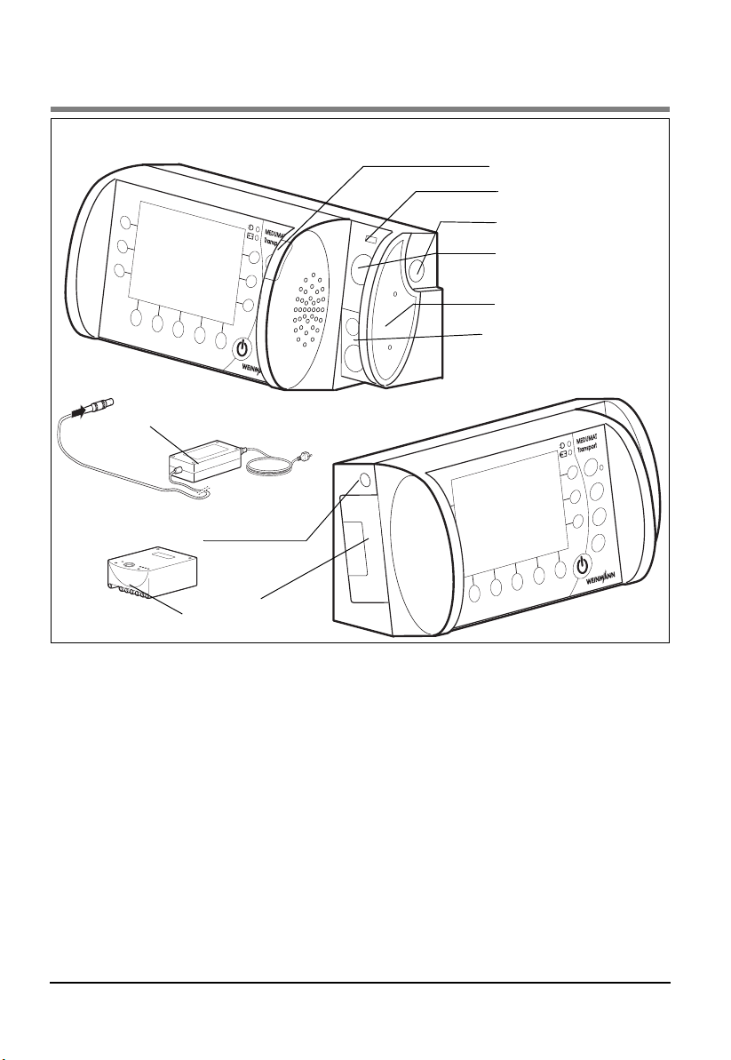
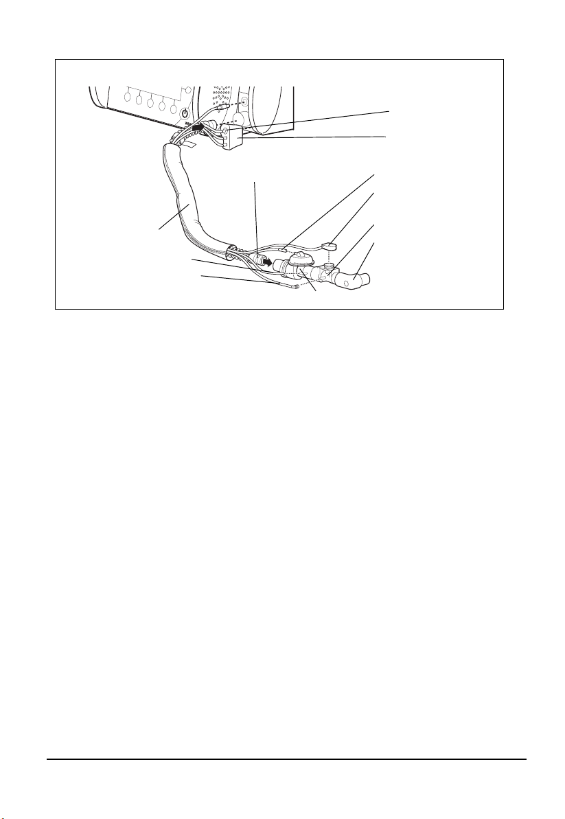
Connections on MEDUMAT Transport
9 External power supply unit
8 DC connection
1 Alarm display
2 USB interface
3 O
inlet
2
4 O2 inlet/outlet
5 Filter compartment
cover, air inlet
6 Ventilation connection
terminal
7 Rechargeable
battery
1 Alarm display
Glows to indicate alarms.
2 USB interface
Means of data transfer for servicing and
maintenance purposes.
3 O2 inlet
Connection point, e.g., for an oxygen cylinder.
4 O2 inlet/outlet
At this connection point, oxygen can be
extracted, e.g., using an inhalation device, or
an oxygen source can be connected.
5 Filter compartment cover, air inlet
Covers the filter and ensures it is securely
positioned.
4 Overview
6 Ventilation connection terminal
The tube system is connected here.
7 Rechargeable battery
Provides mobile power supply to the unit.
8 DC connection
For DC power supply via an external power supply
unit or via the electrical circuit of an ambulance or
rescue vehicle.
9 External power supply unit
Provides power supply to the unit via a 100V 240V grid.
Page 5
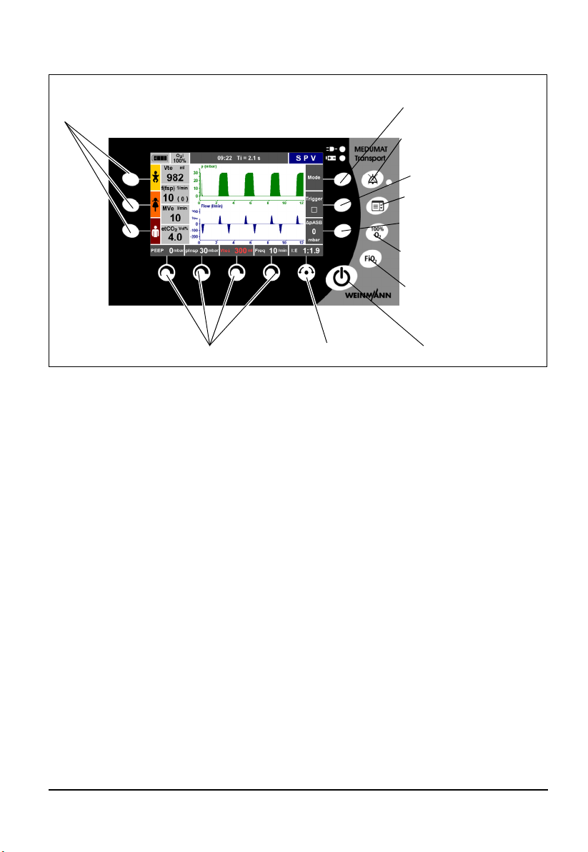
Controls of MEDUMAT Transport
11Function buttons for
emergency ventilation
10 Context-dependent control knobs
9 Navigation knob
1 Context-dependent
function button
2 Alarm mute button with
LED
3 Context-dependent
function button
4 Function button for
main menu
5 Context-dependent
function button
6 Function button for
100% O
2
7 Function button for
inspiratory O
concentration
8 On/Standby/Off
button
2
1, 3, 5 Context-dependent function button
These buttons are used to set various ventilation
parameters, depending on the ventilation mode
selected.
2 Alarm mute button with LED
With this button, acoustic alarms can be muted
briefly (for 2 minutes). If alarms are muted, the
LED lights up. Visual alarms are still displayed.
4 Function button for main menu
This button calls up the main menu.
6 Function button for 100% O
This button calls up the 100% O2 function to ventilate the patient briefly (2 minutes) with
100% O
(FiO2 = 1.0).
2
2
7 Function button for inspiratory O2
concentration
This button calls up the O2 concentration menu.
The required inspiratory O
respiratory gas can be set in this menu.
concentration in the
2
8 On/Standby/Off button
A short press switches the unit on and off. A long
press switches it off completely.
9 Navigation knob
For navigating in menus and confirming your settings on the unit. During ventilation, this knob is
to set the I:E ratio.
10 Context-dependent control knobs
For setting various parameters, depending on
which ventilation mode is active. Settings made
here must be confirmed with the Navigation
knob.
11 Function buttons for emergency
ventilation
These buttons start emergency ventilation. By
pressing the buttons, preset parameters for
infants, children or adults are activated.
Overview 5
Page 6
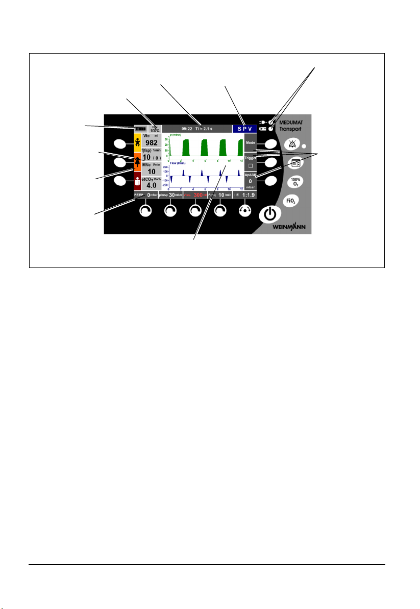
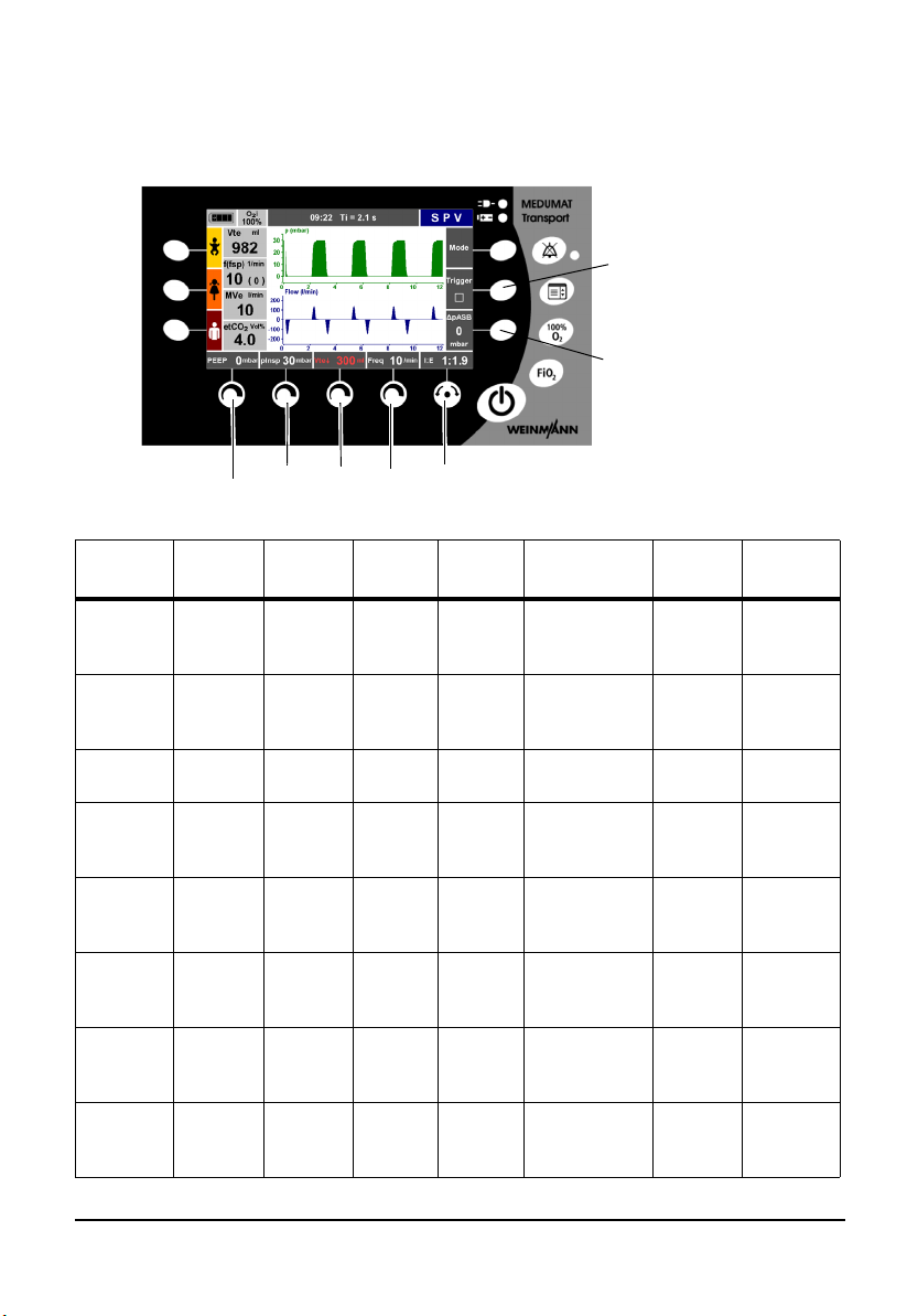
Display of MEDUMAT Transport
1 Battery/Line operation indicators
8 Indicator for inspiratory
O
concentration (FiO2)
2
7 Battery
charge
status
6 Numeric mea-
surement display
5 Function indica-
tor for contextdependent function buttons
4 Function indica-
tor for contextdependent control knobs
9 Info field
3 Ventilation progress display
1 Battery/Line operation indicators
Indicates whether the unit is being operated with
the external power supply unit (upper LED) or
with the internal battery (lower LED).
2 Function indicator for context-
dependent function buttons
The currently available function of the contextdependent function buttons is indicated here.
3 Ventilation progress display
Here, the ventilation progress is displayed in up to
three graphs (ventilation pressure, ventilation
flow, CO
tilator version. In the case of emergency
ventilation, a pressue gauge is displayed.
concentration), depending on the ven-
2
4 Function indicator for context-
dependent control knobs
The currently available function of the contextdependent control knobs is indicated here.
5 Function indicator for context-
dependent function buttons
The three directly selectable emergency ventilation modes (infant, child, adult) are indicated here.
6 Numeric measurement display
The current measurements are indicated
numerically here.
10Mode indicator
2 Function
indicator for
contextdependent
function
buttons
7 Battery charge status
The battery charge status is indicated here.
8 Indicator for inspiratory O2
concentration (FiO2)
The inspiratory O2 concentration (FiO2) is
indicated here.
9 Info field
Information (error messages, visual alarms) about
the state of the patient and the ventilator is displayed here. The time of day is also displayed in
this field.
10 Mode indicator
The ventilation mode set by the user is indicated
here.
6 Overview
Page 7
Hose system (reusable and disposable versions available)
2 Water filter for CO2
measurement
3 Connector
1 Ventilation hose
11Tube protec-
tion sleeve
10Pressure-
measurement tube
9 CO
removal tube
2
1 Ventilation hose
The respiratory gas flows through the respiration
tube to the patient valve.
2 Water filter for CO2 measurement
The water filter protects the measuring chamber
of the MEDUMAT Transport against moisture
from the patient's respiratory gas.
3 Connector
The measurement-tube system is connected to
MEDUMAT Transport by means of this connector.
4 PEEP control tube
With this tube, MEDUMAT Transport controls the
patient valve and the PEEP.
5 BiCheck flow sensor connection line
This electric lead transfers the measuring signals
from the BiCheck flow sensor to the MEDUMAT
Transport.
6 BiCheck flow sensor
This sensor supplies monitoring data on flow,
MV
, Vte and f.
e
4 PEEP control tube
5 BiCheck flow sensor
connection line
6 BiCheck flow sensor
7 Elbow
8 Patient valve
7 Elbow
The mask/tube is connected here. The elbow is removable, i.e., the mask/tube can also be connected to the BiCheck flow sensor itself,
depending on the position of the patient.
8 Patient valve
Switchover between inspiration and expiration
happens here.
9 CO2 removal tube
Test gas is removed via this tube if your unit is
equipped with the optional CO
facility.
measurement
2
10 Pressure- measurement tube
For patient-side measurement of ventilation
pressure.
11 Tube protection sleeve
Protects tubes and leads against soiling and
damage.
Note
Detailed information about the hose systems can be found in the “Patient Hose
System“ instruction manual WM 66696.
Overview 7
Page 8
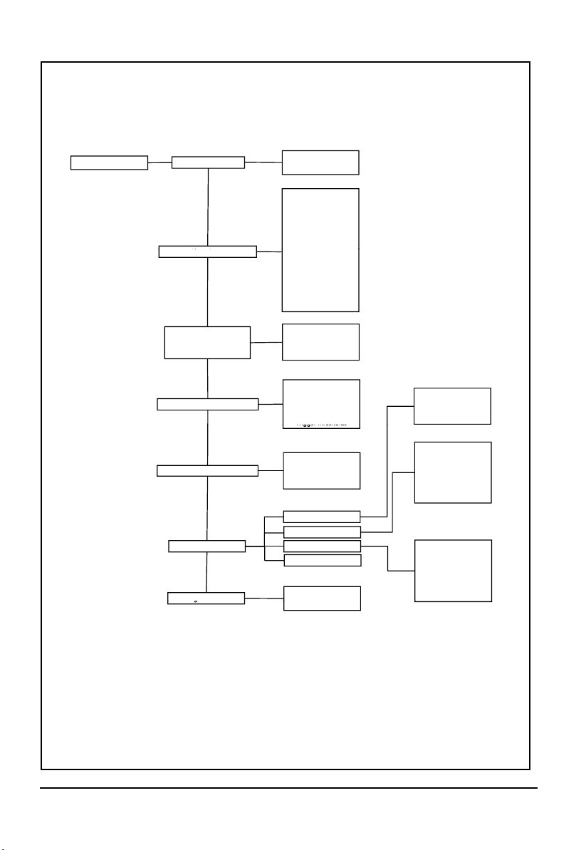
MEDUMAT Transport Main menu
no
Mai
n menu
Aut
omatic alarm limits
yes
Automatic alarm limits
Vte n
Vte p
MVe n
MVe p
Al
arm Limits
Curves
Pressure, flow
f n
Apnoea
etCO
2
n
etCO
2
p
CO
2
i n
(Only CO2measurement
option)
Pressure, CO
2
Pressure, flow, CO
2
Pressure ramp
Flow ramp
Flow progress
Tri
r thrhl
Advanced ventilation parameters
mmHg
Vol%
kPa
Audio/Video
Trigger thresholds
Brightness/Day
Brightness/Night
Volume
Year
Month
Day
Hour
Minute
Options
Night colours
activate
Deutsch
English
Español
Italiano
…
CO2configuration
Date, time
Language
Device data
g
deactivate
MEDUMAT Transport Main menu
8 Overview
Page 9
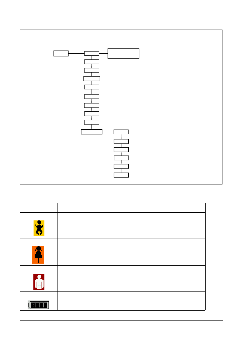
Mode menu
Mode
BILEVEL
NIV
PCV
activate
deactivate
IPPV
CPAP + ASB
SIMV
S-IPPV
20 l/min
25 l/min
SPV
Preoxygenation
SVV
15 l/min
5 l/min
10 l/min
Off
Symbols used on the display
Symbol Meaning
Emergency mode - Infant
Emergency mode - Child
Emergency mode - Adult
Battery status indicator
Overview 9
Page 10
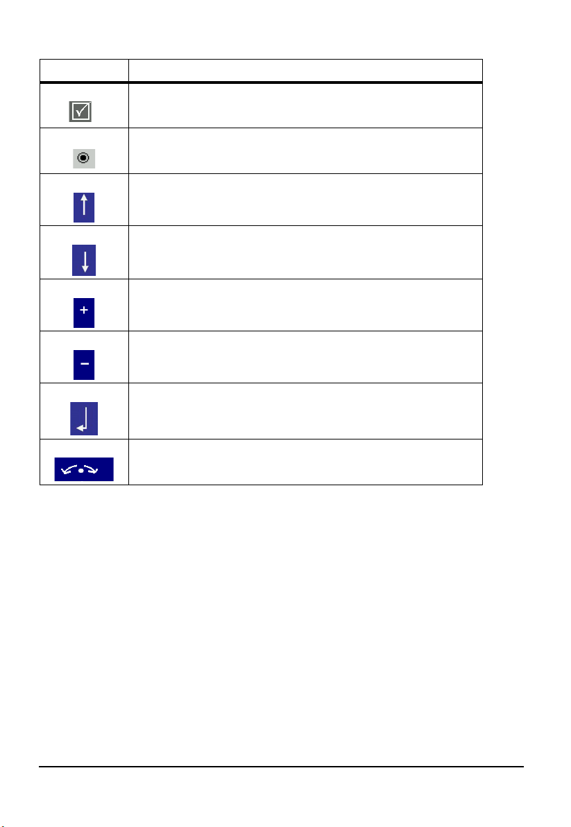
Symbol Meaning
Tick box: option activated
Radio button: function selected
Navigate upwards
Navigate downwards
Increase value
Decrease value
Confirm your selection
Navigation knob active
10 Overview
Page 11
Function of the controls during ventilation
Depending on the ventilation mode selected, you can set the following ventilation
parameters using the controls:
7
6
1 2345
Ventilation
mode
SVV
SPV
CPAP + ASB
BILEVEL
PCV
IPPV
S-IPPV
SIMV
Control
knob
PEEP p
PEEP p
CPAP - V
PEEP p
PEEP p
PEEP p
PEEP p
PEEP p
Control
1
knob 2
max
insp
insp
insp
max
max
max
Control
knob 3
V
t
V
tmin
tmin
V
tmin
V
tmin
V
t
V
t
V
t
Control
knob 4
Freq.
Freq.
-
Freq.
Freq.
Freq.
Freq.
Freq.
Navigation knob 5Function
button 6
I:E and
Selection/
Confirmation
I:E and
Selection/
Confirmation
Only Selection/
Confirmation
I:E and
Selection/
Confirmation
I:E and
Selection/
Confirmation
I:E and
Selection/
Confirmation
I:E and
Selection/
Confirmation
I:E and
Selection/
Confirmation
Δ
pASB Trigger
Δ
pASB Trigger
Δ
pASB
Δ
pASB Trigger
--
--
--
--
Function
button 7
−
Overview 11
Page 12
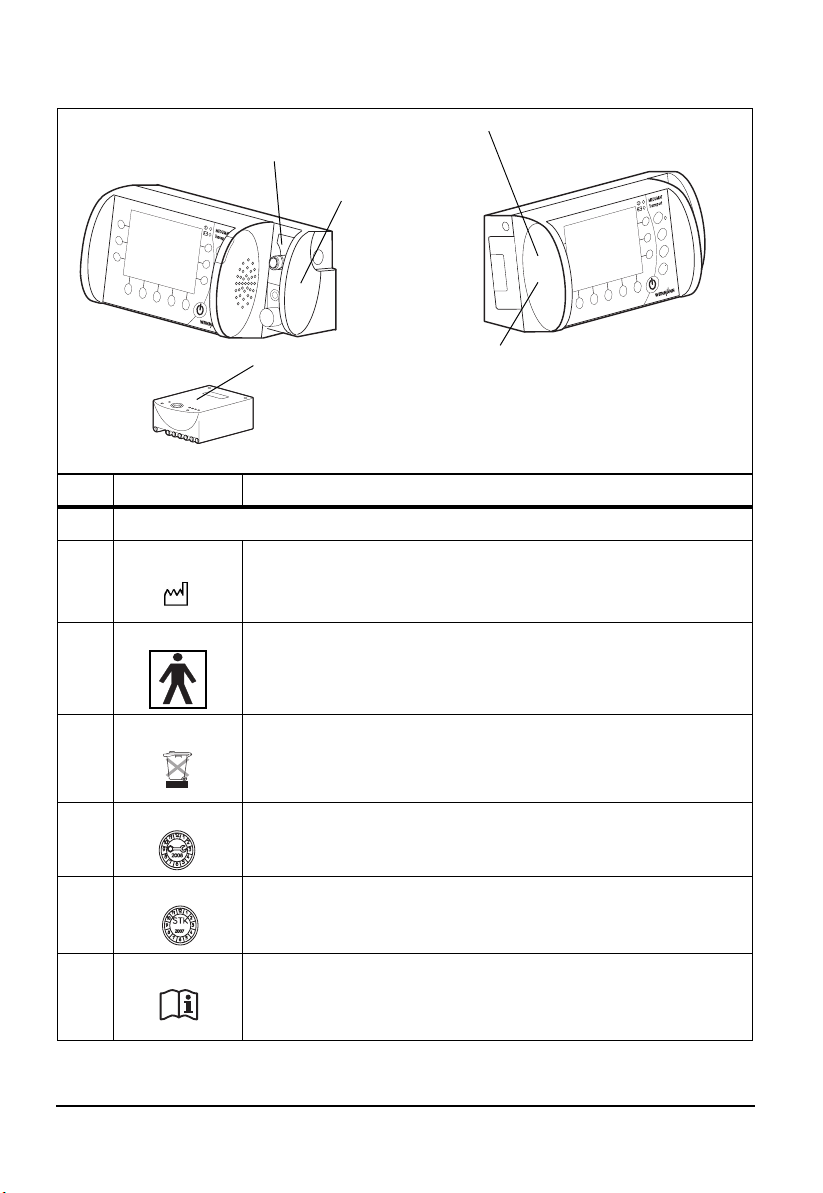
Symbols used on the unit
MEDUMAT Transport
5 Cover of USB interface
1 MEDUMAT Transport type plate
4 Filter compart-
ment cover
Battery
1
1
1
2
2
1, 4, 5
3 Rechargeable
battery type plate
2 STK and service label
Symbol Meaning
MEDUMAT Transport type plate
Year manufactured
Type BF device
Do not dispose of the unit in the household waste
Service label: indicates when the next service is required.
STK label: (only in the Federal Republic of Germany) indicates
when the next safety check in accordance with §6 Medical Device
Operator Ordinance (MPBetreibV) is required.
Observe the information in the instruction manual.
12 Overview
Page 13
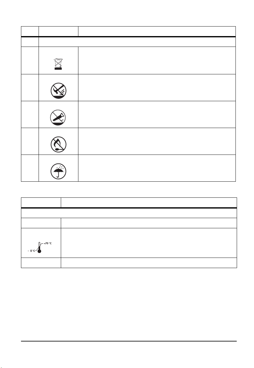
Symbol Meaning
Rechargeable battery type plate
3
Do not dispose of the unit in the household waste.
3
Do not subject the unit to hard knocks or shocks.
3
Do not open the unit using force.
3
Protect the unit against heat.
3
Protect the unit against moisture.
Labeling on the packaging
Symbol Meaning
MEDUMAT Transport:
SN
Serial number of the unit
3
RH % 0-95
Permissible storage temperature: -30°C to +70°C
Permissible humidity for storage: up to 95% relative humidity
Overview 13
Page 14

Safety information in this manual
The safety instructions in this instruction manual are marked as follows:
Warning!
Warns of risk of injury and possible damage to the unit.
Caution!
Warns of material damage and possibly incorrect therapy results.
Note:
Offers useful tips.
14 Overview
Page 15

2. Description
2.1 Intended use
The MEDUMAT Transport is an automatic oxygen emergency ventilator with additional
preoxygenation and monitoring functions (pressure, flow and CO
MEDUMAT Transport is used for controlled and assisted, as well as for invasive and noninvasive, ventilation of persons with a respiratory volume of 50 ml upwards.
MEDUMAT Transport must only be operated when installed permanently or on approved
portable systems.
2.2 Applications
MEDUMAT Transport can be used in the following cases:
Emergency
• for resuscitation at the place of the emergency
• for longer-tem use in continuing emergency situations
• for preoxygenation via a ventilation mask
).
2
Transport
• in ground, sea and air emergency medical service
• between hospital rooms and departments
• between a hospital and other locations (secondary transport)
Short-term ventilation in hospitals
• recovery room
• intensive care unit
• surgery preparation and follow-up
• emergency department
MEDUMAT Transport is also suitable for gentle ventilation of anesthetized patients (TIVA:
total intravenous anesthesia).
Description 15
Page 16

2.3 User qualification
MEDUMAT Transport must only be used by persons who can verify that they have the
following qualifications:
• A medical qualification and training in ventilation techniques.
• Training in the use of the MEDUMAT Transport by a person authorized
by WEINMANN.
Improper use may lead to serious physical injury.
2.4 Function
The unit
MEDUMAT Transport is used to treat apnea and to provide respiratory support. By means
of adjustable ventilation parameters, the unit ensures uniform ventilation tailored to the
patient.
Four pressure-controlled ventilation modes (SPV, CPAP + ASB, BIPAP, PCV) and four volume-controlled ventilation modes (SVV, IPPV, S-IPPV, SIMV) can be selected to provide optimum patient ventilation.
In CPAP + ASB mode, the unit enables assisted spontaneous breathing with continuous
positive airway pressure and respiration-controlled oxygen inhalation. In addition, the unit
permits O
The unit allows the oxygen concentration of the respiratory gas to be adjusted.
Depending on the version, the unit's large display can show up to three spirometric graphs
(pressure, flow and CO
For emergency situations, rapid selection of default types of ventilation is possible.
inhalation for preoxygenating the patient.
2
).
2
16 Description
Page 17

Patient Hose System
The ventilation gas is supplied to the patient via the Patient Hose System, comprising the
ventilation hose and all leads necessary for comprehensive ventilation and monitoring.
The Patient Hose System is designed to permit spontaneous respiraton even if the
MEDUMAT Transport malfunctions.
The Patient Hose System is available in two versions:
• Reusable hose system
• Disposable hose system
Description 17
Page 18
3. Installation
As a rule, MEDUMAT Transport only has to be installed for stationary use in rescue vehicles,
helicopters or aircraft. In this case, fastening sets can be supplied as accessories.
If MEDUMAT Transport is supplied complete on a portable system, the unit is ready for
operation and no further installation work is required. There are separate instruction
manuals for the portable systems.
Warning!
After installation, you must perform a functional check (see “8. Function check” on
page 74) to ensure reliable operation.
3.1 Connecting oxygen cylinder
Warning!
• Risk of explosion! Wash your hands thoroughly before doing any work
on the oxygen supply. Hydrocarbon compounds (e.g. oil, grease,
cleaning alcohol, hand cream or adhesive plasters) can cause explosive
reactions if they come into contact with highly compressed oxygen.
• Never use wrenches or other tools to tighten or unscrew the union nuts.
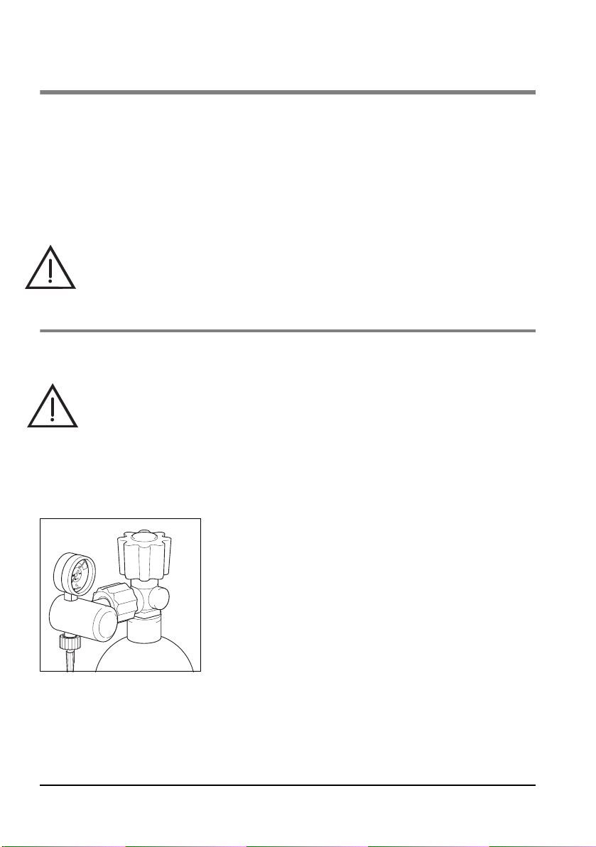
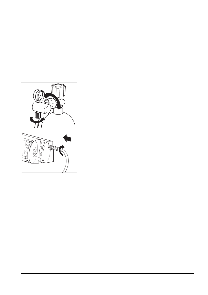
Removing the empty cylinder
1. Close the valve on the oxygen cylinder.
Switch on MEDUMAT Transport at the On/Standby/Off
switch. This allows the remaining oxygen to escape and
the unit is pressure-free. Only when the contents gauge
on the pressure reducer indicates 0 bar, can the
screwed union be undone by hand.
2. Switch MEDUMAT Transport off again.
3. Undo the screwed union at the cylinder by hand.
18 Installation
Page 19
Connecting a new cylinder
1. Briefly open the valve of the new oxygen cylinder, then shut it again. This is to blow
away any particles of dust.
Caution!
• Make sure that the patient is not connected up to the MEDUMAT
Transport when you are establishing the gas supply. Otherwise, the
unit’s automatic self-test will lead to incorrect results.
• When doing this, hold the valve opening away from your body in such a
way that any flying particles cannot injure yourself or other people!
2. Screw the pressure reducer to the cylinder valve using
the knurled union nut. Tighten the union nut by hand.
3. Screw the pressure hose onto the outlet of the pressure
reducer (if not already connected) using the G 3/8
union nut.
4. Screw the other end of the pressure hose to the
compressed gas connection of the MEDUMAT
Transport (if not already connected).
Connecting a second oxygen source
Caution!
• Risk of insufficient oxygen supply
Two oxygen sources can be connected to this unit simultaneously. Make
sure that only one oxygen source is open at any given time and that there
is no gas reflux. Otherwise, one of the oxygen sources may empty itself
unnoticed. Sufficient oxygen supply to the patient can then no longer be
guaranteed when the unit is in use.
If desired or if foreseen in your establishment, you can connect a second oxygen source, e.g.,
an oxygen cylinder or a CGC to the O2 inlet/outlet (quick connector to the front of the unit).
Note:
If your unit is equipped with a DIN quick connector, no oxygen can be fed into the
unit with the associated DIN gas probe. With this combination it is only possible to
draw off oxygen.
Installation 19
Page 20
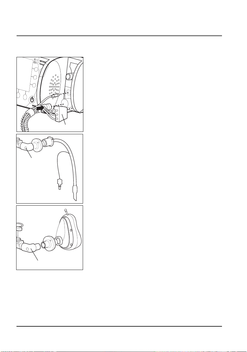
3.2 Hose system
A reusable hose system is supplied with the MEDUMAT Transport. Optionally, a disposable
hose system is also available. The procedure for connecting both systems is as follows:
1. Press the ventilation hose onto the corresponding
connection on the unit.
2. Attach the connector of the BiCheck flow sensor
connection line to the corresponding connection on the
unit.
3. Press the connector (contains PEEP control line, CO
removal tube, pressure-measurement tube) onto the
corresponding connection on the unit. Make sure that
the connected tubes are not kinked.
Connector
Elbow
Caution!
Only grip the ventilation hose by its ends. Otherwise the
hose may be damaged.
4. Connect the patient valve with BiCheck flow sensor to
the hose following intubation. If performing mask
ventilation, attach the ventilation mask to the patient
valve with the BiCheck flow sensor (identical to tube
connection).
2
Elbow
20 Installation
Note!
You can remove the elbow to reduce the dead space or
to adapt the hose routing to suit the patient's position.
Page 21

Tube protection sleeve
The tube protection sleeve is pulled over the ventilation
hose with connected BiCheck flow sensor. It prevents the
hose system from tangling on other items of equipment
and being damaged.
Water filter for CO2 removal tube
The water filter WM 97012 loses efficiency after approx. 8 hours of continuous operation,
depending on the temperature, humidity and any coarse particles, such as mucus.
Change the filter after eight hours at the latest.
The filter's decreasing efficiency is indicated by the alarm message “CO
display. This message is accompanied by a low-priority audible alarm
occlusion“ on the
2
3.3 Accessories from other manufacturers
Caution!
The unit's USB interface is intended exclusively for use by the manufacturer or an
authorized technician for servicing work. Do not connect equipment of any sort to
the USB, as this will interfere with operation of the unit, putting the patient at risk.
HME filter/bacterial filter/combined HME bacterial filter
If a filter is used, install it between the patient connection of the BiCheck flow sensor
(optionally with elbow) and the tube or mask. Follow the manufacturer's instructions.
Ventilation mask
Attach the ventilation mask to the BiCheck flow sensor. The mask used must have a
standard connection, as per ISO 5356-1.
Laryngeal mask
You can use a laryngeal mask instead of a ventilation mask. The tube used must have a
standard connection, as per ISO 5356-1.
Installation 21
Page 22

Endotracheal tube
Instead of attaching the BiCheck flow sensor to a ventilation mask, you can attach it to an
endotracheal tube. The tube used must have a standard connection, as per ISO 5356-1.
Tracheostomy tube
Instead of attaching the BiCheck flow sensor to a ventilation mask, you can attach it to a
tracheostomy tube. The tube used must have a standard connection, as per ISO 5356-1.
Supplying oxygen to external units
You can use the O2 inlet/outlet to connect the units, modules or inhalation devices to the
MEDUMAT Transport (quick connector on the front of the units).
When doing so, bear in mind that the outlet gas flow reduces the efficiency of the gas
supply (see 11.5 “Required gas supply” on page 95).
22 Installation
Page 23
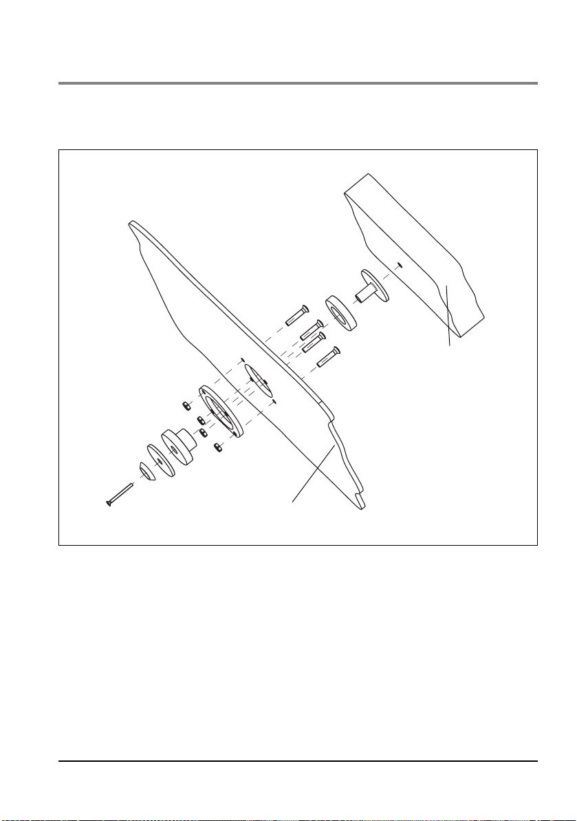
3.4 Permanent installation of the unit
If you wish to install the unit on a portable system or permanently install it in a vehicle or
aircraft, you require the fastening set WM 15730.
Back panel of
MEDUMAT Transport
Portable system
Installation 23
Page 24

4. Safety information
Read this instruction manual carefully. It is part of the unit and must be available at all
times.
For your own safety and that of your patients, and in accordance with the requirements of
Directive 93/42/EEC, please observe the following points:
General
• Always carry out a functional check before using the unit
(see “8. Function check” on page 74).
• Please observe the section “7. Hygienic preparation” on page 70 in
order to avoid infection or bacterial contamination.
Warning!
• Risk of injury. Only use MEDUMAT Transport if you are a qualified
medical professional and have received training in respiration
techniques. Improper use may lead to serious physical injury.
• Risk of injury. Never leave the patient or the ventilator unattended during
ventilation. Only then can you respond quickly if the patient's condition
deteriorates or in the event of an alarm or malfunction. Delayed response
on the part of medical personnel may lead to serious physical injury.
• Only use MEDUMAT Transport for the designated purpose
(see “2.1 Intended use” on page 15).
• MEDUMAT Transport is not suitable for hyperbaric use (pressure
chamber).
• The unit is not licensed for use in explosive atmospheres. The unit must
not be used in combination with flammable gases or anesthetics.
• The unit is not licensed for use in poisonous or contaminated
atmospheres.
• Only have modifications to the unit carried out by the manufacturer,
WEINMANN, or by a technician expressly authorized by WEINMANN.
Caution!
• Do not place a switched-on cellular phone or radio closer than 1 m from
the MEDUMAT Transport, as this could cause malfunctions.
• Remember that the respiratory resistance of the system as a whole may
increase beyond the level specified by the standard when an HME filter
24 Safety information
Page 25

(heat and moisture exchanger), a bacterial filter or a combined HME
bacterial filter is used.
• When operating the unit with the power supply unit, always connect the
unit to an easily accessible outlet so that it can be unplugged quickly in
the event of a malfunction.
• When operating the unit with the power supply unit, make sure that the
power cord cannot cause anyone to trip or cause any obstruction. If
necessary, do not use an external power supply, but operate the unit
with the battery instead.
• When operating the unit with the 12 V supply cord, always connect the
unit to an easily accessible vehicle electrical system receptacle so that it
can be unplugged quickly in the event of a malfunction.
• When operating the unit with the 12 V supply cord, make sure that the
cord cannot cause anyone to trip or cause any obstruction. If necessary,
do not use the vehicle electrical system, but operate the unit with the
battery instead.
• A spare unit must always be kept ready for use in case of failure.
• After using the unit in a dusty environment (e.g., a gravel plant), change
the suction filter, as described in the section “10.4 Changing the suction
filter” on page 87.
Safe handling of oxygen
Warning!
• Risk of explosion! In combination with combustible substances (grease,
oil, alcohol etc.), highly compressed oxygen may give rise to spontaneous
explosive reactions.
• Risk of fire! If only the O
side with a suitable cap. Otherwise, oxygen will escape from the O
on the side.
• Risk of poisoning! Highly concentrated oxygen can have a toxic effect on
the patient if administered for too long and depending on the age of the
patient. When ventilating with pure oxygen or an oxygen-air mixture,
make sure that oxygen is only administered for an appropriate period.
• Keep the units and all screwed unions absolutely free from oil and
grease.
• Be sure to wash your hands before working on the oxygen supply.
• Smoking and open flames are strictly prohibited in the vicinity of fittings
containing oxygen.
inlet/outlet is used, close the O2 inlet on the
2
inlet
2
Safety information 25
Page 26

Caution!
• When assembling the unit, and when changing cylinders, tighten all
screwed unions on the oxygen cylinder and pressure reducer by hand
only. Never use tools. Overtightening damages the threads and seals,
resulting in leaks.
• Secure the oxygen cylinders so that they cannot fall over. If a cylinder falls
on the pressure reducer or valve, these could break off, causing a violent
explosion.
• Risk of insufficient oxygen supply
Two oxygen sources can be connected to this unit simultaneously. Make
sure that only one oxygen source is open at any given time and that there
is no gas reflux. Otherwise, one of the oxygen sources may empty itself
unnoticed. Sufficient oxygen supply to the patient can then no longer be
guaranteed when the unit is in use.
• Always open the cylinder valve slowly to prevent pressure hammer on the
fittings.
• Do not empty oxygen cylinders completely, as this may allow moist
ambient air to enter and cause corrosion.
Ventilation/Handling
• Patient and emergency ventilator must be kept under continuous
observation during ventilation.
• Prolonged ventilation can lead to atrophy of the muscles (dependency of
the patient on ventilation).
• Prolonged ventilation may lead to the airway drying out. Ensure
adequate conditioning of the respiratory air.
• Only apply high ventilation pressures for short periods and only if
medically indicated. Permanently applied high ventilation pressures can
be injurious to the patient.
• Make sure that the patient valve is not covered or its function impaired,
e.g. by the patient's position.
26 Safety information
Page 27

Patient Hose System
Warning!
• Risk of injury. Only use the Patient Hose System if you are a qualified medical
professional and have received training in respiration techniques. Improper use
may lead to serious physical injury.
• The Patient Hose System must be subjected to a functional check and visual
inspection by the user before use. For this, refer to the instruction manual for the
Patient Hose System.
• When connecting the patient valve, check that the direction of flow of the
respiratory gas is correct. Make sure that the expiration opening of the patient
valve is not covered or prevented from functioning, e.g., by the patient's
position.
• Only use the Patient Hose System for the purpose described. For this, refer to
the instruction manual for the Patient Hose System.
• The Patient Hose System is not suitable for hyperbaric use (pressure chamber).
• Also refer to the instruction manual for the Patient Hose System.
Software
• Risks due to software errors have been minimized by means of extensive
qualification measures.
Accessories/Repairs/Replacement parts
Caution!
• Protect silicone/rubber parts against UV light and prolonged direct
exposure to sunlight to prevent them becoming brittle.
• We recommend that work such as inspections and repairs should be
carried out by the manufacturer, WEINMANN, or by a technician
expressly authorized by WEINMANN.
• If third-party items are used, functional failures may occur and fitness for
use may be restricted. Biocompatibility requirements may also not be
met. Please note that in such cases, any claim under warranty and liability
will be voided if neither the accessories nor genuine replacement parts
recommended in the instructions for use are used.
Safety information 27
Page 28
5. Operation
5.1 Controls
Display
The display contains the following information while the
unit is in use.
• Progress of the current ventilation
• Current measurements
• Ventilation parameters set/to be set
• Current assignment of the context-dependent
function buttons and control knobs
• Alarms and error messages
Function buttons with fixed assignment
The fixed-assignment function buttons enable you to carry
Function but-
tons with fixed
assignment
out the following actions directly:
• Mute acoustic alarms
• Call up the main menu
• Activate the “100% O
• Call up the “O
“ function
2
concentration“ menu
2
28 Operation
Page 29
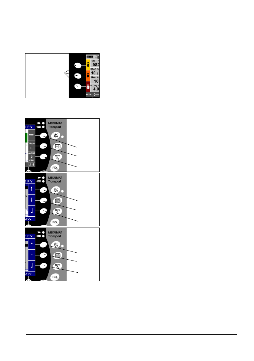
Context-dependent function buttons
On both sides of the display there are context-dependent
function buttons for calling up the following functions:
Left side of the display:
Function buttons
for emergency
ventilation
Context-
dependent
buttons
1
2
3
Context-
dependent
buttons
1
2
3
Context-
Context-
dependent
dependent
buttons
buttons
1
2
3
• Selecting emergency modes (available in every
ventilation mode):
– Infant (approx. 10 kg)
– Child (approx. 25 kg)
– Adult (approx. 75 kg)
Right side of the display:
• Calling up menus during ventilation:
–Button 1: Selecting a ventilation mode
–Button 2: Activating/deactivating triggers in SVV,
SPV, BILEVEL modes
–Button 3: Setting the pressure level of the ASB
function (ASB=Assisted Spontaneous Breathing in
SVV, SPV, BILEVEL and CPAP + ASB modes)
• Navigating in a menu:
–Button 1: Up
–Button 2: Down
–Button 3: Confirm your selection
Alternatively, these settings can also be made with the
navigation knob (Dual Navigation).
• Setting a parameter:
–Button 1: Increase value
–Button 2: Decrease value
–Button 3: Confirm your selection
Alternatively, these settings can also be made with the
navigation knob (Dual Navigation).
Operation 29
Page 30
Navigation knob
When a menu is open, you can navigate using the
navigation knob, as follows:
• Turn counterclockwise: to move the selection bar
upwards in the menu
• Turn clockwise: to move the selection bar
downwards in the menu
Navigation knob
• Press navigation knob to confirm your selection
When no menu is open, you can carry out the following
functions:
• Confirm setting parameters that have been set
with the context-dependent control knobs.
• Set and confirm the I:E ratio
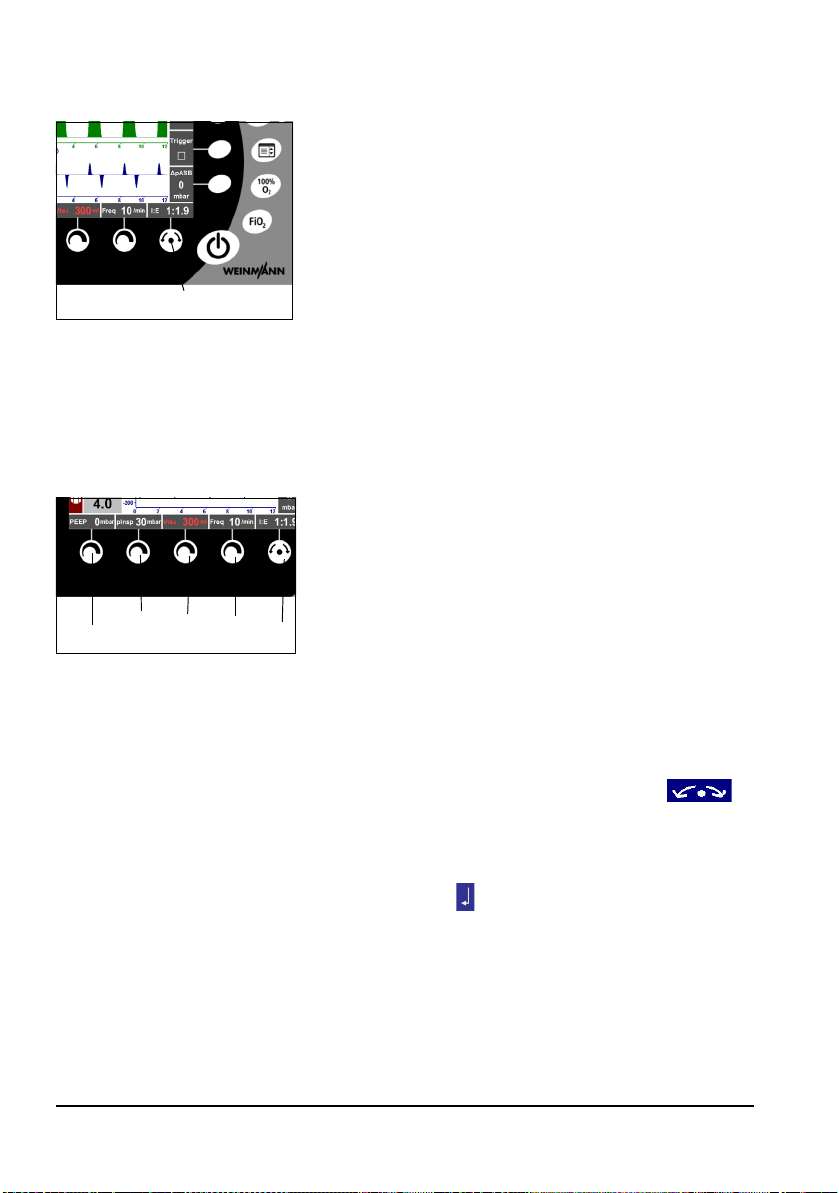
Context-dependent control knobs
Depending on the ventilation mode selected, you can set
the following parameters using the control knobs:
• Control knob 1: PEEP, CPAP
• Control knob 2: p
1 2345
ventilation modes, this knob has no function
• Control knob 3: V
• Control knob 4: Respiratory rate (no function in
some modes)
• Navigation knob 5: I:E (no function in some modes)
If the ventilation parameters are changed using the control
knobs, the corresponding parameters and the
above the navigation button will flash for 5 seconds.
Changed parameters that are not confirmed within
5 seconds by the navigation button or the contextdependent button will not be applied.
(alarm limit), P
max
, Vte ↓ (alarm limit)
t
. In some
insp
30 Operation
Page 31

5.2 Switching the unit on/Self-test
1. Slowly open the valve on the oxygen cylinder. The contents gauge now indicates the cylinder pressure.
2. Calculate the remaining operating time (see 5.14 “Calculating the oxygen level/operating time”on page 53).
You should change the cylinder in good time, e.g.,
when the pressure falls below 50 bar, to ensure a sufficiently long operating time.
3. To switch on MEDUMAT Transport, press the On/
Standby/Off button. An automatic self-test runs.
During the self-test, the alarm LED lights up briefly. The
buzzer gives a series of five signals and then the
loudspeaker gives two acoustic signals.
On/Standby/Off button
If the self-test is not successful, the “Fault“ message
appears in the display. The unit cannot then be
operated.
Caution!
The automatic self-test is not a substitute for the
functional check. Before using the unit, always carry
out a functional check, as described in Section
“8. Function check” on page 74. That is the only way
to ensure that the unit is fully functional.
4. The “Start menu“ appears on the display. You now
have the following options:
– Press one of the emergency buttons (Infant, Child,
Adult). The unit immediately begins ventilation
with preset parameters.
– Do not make any selection: after 20 seconds the
“Start menu“ will disappear. The unit begins
ventilation in the mode that was last selected and
with the parameters last set.
Operation 31
Page 32

– Press the “Last patient“ button: The unit
immediately begins ventilation in the last mode
selected.
– Press the “New patient“ button: Then select the
“Adult“, “Infant“ or “Child“ setting. The “Mode“
menu appears. Select the appropriate ventilation
mode and confirm your selection. Use the control
knobs to set the parameters for ventilating the
patient. Then select “Start ventilation“ with the
context-dependent buttons if you are ready to start
ventilation, or select “Back“ if you wish to change
the settings.
– Select the “Functional check“ menu, and the unit
will begin the automatic functional check (see 8.4
“Automatic function check”on page 77).
5. When the self-test has finished and the ventilation
mode has been set, connect the patient.
6. During ventilation, make any necessary changes to the
ventilation values, as described later in this section.
32 Operation
Page 33

5.3 Navigating in menus
The vast majority of functions of the MEDUMAT Transport are accessed via menus.
MEDUMAT Transport offers two methods of navigating in these menus:
• using the navigation knob
• using the context-dependent function buttons on the right of the display.
Menus can be closed at any time by pressing the Menu button again. If no parameters are
changed, the menus close automatically after 20 seconds.
Parameter changes will not be implemented unless they are confirmed with the navigation
knob or context-dependent button .
Navigating with the navigation knob
1. Select a menu using the function buttons (here: Alarm
limits).
2. Select a menu item by turning the navigation knob
clockwise (the selection bar moves downwards) or
counterclockwise (the navigation bar moves upwards).
3. Confirm your selection by pressing the navigation
knob.
4. To leave a menu, select the menu item “Back“ using
the navigation knob, and confirm your selection by
pressing the navigation knob.
Proceed in the same way when making numeric
settings (here: Alarm limits):
Navigation knob
– Turn the navigation knob clockwise to raise the
value, and counterclockwise to lower it.
– Press the navigation knob to confirm the newly set
value.
5. To switch from a sub-menu direct to the ventilation
screen, press the function button for “Main menu“
again.
Operation 33
Page 34

Navigating with the context-dependent function buttons.
1. First, select a menu using the function buttons (here:
Main menu).
2. Select a menu item by pressing the function button
(the selection bar moves downwards) or the button
(the navigation bar moves upwards).
3. Confirm your selection by pressing the button.
4. To leave a menu, select the menu item “Back“ using
the or button, and confirm your selection by
pressing the button.
Proceed in the same way when making numeric settings
(here: Alarm limits):
– Press the button to raise the value and the
button to lower it.
– Press the button to confirm the newly set value.
5. To switch from a sub-menu direct to the ventilation
screen, press the function button for “Main menu“
again.
Other symbols used in the menus:
Radio button:
If a menu contains functions which have a so-called “radio
button“, only one function at a time can be selected in this
menu.
Tick box:
If a menu contains functions which have a so-called “tick
box“, these functions can be activated in addition to other
functions.
34 Operation
Page 35

5.4 Emergency modes
Three modes with preset ventilation parameters are available for emergency ventilation. You can select these at any
Context-
dependent
buttons
1
2
3
IPPV ventilation is started with preset parameters. These are optimized for the following
patient groups:
• Infant (approx. 10 kg body weight)
• Child (approx. 25 kg body weight)
• Adult (approx. 75 kg body weight)
Parameter Adult Child Infant
PEEP
p
max
I:E
Frequency
V
0 mbar 0 mbar 0 mbar
30 mbar 25 mbar 20 mbar
1:1.7 1:1.7 1:1.7
12/min 20/min 30/min
600 ml 200 ml 100 ml
t
time during ventilation by pressing the context-dependent
function buttons on the left of the display twice.
• Button 1: Infant
• Button 2: Child
• Button 3: Adult
All three emergency modes are based on the IPPV ventilation mode (see “IPPV”on page 43). This mode is activated
automatically when you call up an emergency mode from
another ventilation mode, e.g. SVV.
Operation 35
Page 36

5.5 Selecting a ventilation mode
MEDUMAT Transport offers the following ventilation modes. Details about the individual
modes are given on the pages indicated below.
Pressure-controlled ventilation modes
• SPV (see “SPV“ on page 38)
• CPAP + ASB (see “CPAP + ASB“ on page 39)
• BILEVEL (see “BILEVEL“ on page 40)
• PCV (see “PCV“ on page 41)
Volume-controlled ventilation modes
• SVV (see “SVV“ on page 42)
• IPPV (see “IPPV“ on page 43)
• S-IPPV (see “S-IPPV“ on page 44)
• SIMV (see “SIMV“ on page 45)
To select a ventilation mode, proceed as follows:
1. First, select the “Mode“ menu using the “Mode“
function button.
2. Select the ventilation mode you require using the navigation knob or the context-dependent function buttons on the right of the display. If necessary, you can
additionally activate the NIV function.
3. Confirm your selection by pressing the navigation knob
or the corresponding context-dependent function
button.
Note:
In combined ventilation modes, breaths can be triggered by the patient within a time
slot of 20% (depending on the rate) or 100% (S-IPPV mode) before the mandatory
breath is initiated.
36 Operation
Page 37

NIV
NIV: Non-Invasive Ventilation (mask ventilation)
This additional function can be activated in all the ventilation modes. The leakage alarm is
deactivated. The unit uses optimised trigger points for the NIV mode.
Caution
• If the NIV function is not activated during ventilation with leakages, the
unit can only be triggered by the patient by greatly increased respiratory
efforts. This may endanger the success of treatment.
• In certain circumstances, the required O
achieved during ventilation with leakages. This is for technical reasons
and is not a malfunction. When the NIV mode is activated, the alarm limit
is therefore automatically set to 20%.
concentration may not be
2
Preoxygenation
1. Call up the “Mode“ menu by pressing the corresponding function button.
2. Select the “Preoxygenation“ function in the “Mode“
menu, and confirm your selection.
3. Select the liter capacity you require using the navigation
knob, and confirm your selection.
The selected liter capacity is indicated in the blue Mode
field on the screen.
4. To end preoxygenation, select “Off“ and confirm your
selection. The “Preoxygenation“ menu is closed. The
“Mode“ menu is displayed.
Changing to a different ventilation mode
If you change from one ventilation mode to another, the unit will respond as follows:
• Ventilation parameters which are also available in the new ventilation
mode are retained unchanged.
• Ventilation parameters which are not available in the new ventilation
mode are saved, but have no influence on the current ventilation. The
saved values become available again as soon as the previous ventilation
mode is reactivated.
• When changing from volume-controlled ventilation to pressure-controlled ventilation, the inspiratory pressure is limited to 15 mbar.
Operation 37
Page 38

5.6 Pressure-controlled ventilation modes
SPV
SPV: Smart Pressure Ventilation
SPV mode is used for pressure-controlled ventilation with
fixed pressure levels.
This mode offers maximum flexibility: By selecting suitable
parameters, all other ventilation modes that are integrated
in MEDUMAT Transport can be implemented.
You can set the following ventilation values using the control knobs:
• Control knob 1: PEEP
• Control knob 2: P
• Control knob 3: V
• Control knob 4: Respiratory rate
• Navigation knob: I:E or T
• You can set the following parameters using the context-dependent
function buttons on the right of the display.
•Button 1: Select a different ventilation mode
•Button 2: Activate/deactivate trigger
•Button 3:
You can find more setting options under the menu item “Advanced ventilation parameters“ in the “Main menu“ (see 6.4 “Setting advanced respiratory parameters”on page 63).
Δ pASB
insp
↓ (alarm limit)
te
at a breathing rate < 6/min.
i
38 Operation
Page 39

CPAP + ASB
CPAP: Continuous Positive Airway Pressure
ASB: Assisted Spontaneous Breathing
CPAP mode is used to increase the pressure level of
respiration in order to raise the functional residual capacity
(FRC).
ASB mode is used for pressure support of insufficient
spontaneous respiration. The patient is able to breathe
spontaneously without any restriction, but is supported in
his breathing effort by the MEDUMAT Transport.
The CPAP + ASB mode is used exclusively on patients with adequate spontaneous respiration.
You can set the following ventilation values using the
control knobs:
• Control knob 1: CPAP
• Control knob 2: No function
• Control knob 3: V
• Control knob 4: No function
• Navigation knob: No function
You can set the following parameters using the context-dependent function buttons on
the right of the display.
• Button 1: Select a different ventilation mode
• Button 2: No function
• Button 3:
Δ pASB
You can find more setting options under the menu item “Advanced ventilation parameters“ in the “Main menu“ (see 6.4 “Setting advanced respiratory parameters”on page 63).
↓ (alarm limit)
te
Operation 39
Page 40

BILEVEL
BILEVEL: Positive airway pressure during inspiration and expiration
BILEVEL mode is used for pressure-controlled ventilation
combined with free spontaneous respiraton during the
entire breathing cycle and for adjustable pressure support
at PEEP level.
This mode is used on patients who have no spontaneous
respiration or on spontaneously breathing patients prior to
extubation. This mode can also be used for weaning by
gradually reducing the mandatory part of the total minute
volume (MV) and reduction of the support pressure (ASB).
You can set the following ventilation values using the control knobs:
• Control knob 1: PEEP
• Control knob 2: P
• Control knob 3: V
• Control knob 4: Respiratory rate
• Navigation knob: I:E or T
You can set the following parameters using the context-dependent function buttons on
the right of the display.
•Button 1: Select a different ventilation mode
•Button 2: Activate/deactivate trigger
•Button 3:
You can find more setting options under the menu item “Advanced ventilation parameters“ in the “Main menu“ (see 6.4 “Setting advanced respiratory parameters”on page 63).
Δ pASB
insp
↓ (alarm limit)
te
at a respiratory rate < 6/min.
i
40 Operation
Page 41

PCV
PCV: Pressure Controlled Ventilation
PCV mode is used for mandatory pressure-controlled
ventilation with fixed pressure levels.
This mode is used on patients who have no spontaneous
respiration.
You can set the following ventilation values using the control knobs:
• Control knob 1: PEEP
• Control knob 2: P
• Control knob 3: V
• Control knob 4: Respiratory rate
• Navigation knob: I:E or T
You can set the following parameters using the context-dependent function buttons on
the right of the display.
• Button 1: Select a different ventilation mode
• Button 2: No function
• Button 3: No function
You can find more setting options under the menu item “Advanced ventilation parameters“ in the “Main menu“ (see 6.4 “Setting advanced respiratory parameters”on page 63).
insp
↓ (alarm limit)
te
at a respiratory rate < 6/min.
i
Operation 41
Page 42

5.7 Volume-controlled ventilation modes
Caution!
In the volume-controlled modes, the ventilation pressure is limited to p
limitation). An alarm is triggered when this pressure limit is reached. It is then no
longer guaranteed that the set tidal volume is actually released to the patient. In this
event, check the patient’s condition and, if necessary, reset the ventilation
parameters.
max
(pressure
SVV
SVV: Smart Volume Ventilation
SVV mode is used for volume-controlled ventilation with a
fixed tidal volume.
This mode offers maximum flexibility: By selecting suitable
parameters, all other volume-controlled ventilation modes
that are integrated in MEDUMAT Transport can be
implemented.
You can set the following ventilation values using the control knobs:
• Control knob 1: PEEP
• Control knob 2: p
• Control knob 3: V
• Control knob 4: Respiratory rate
• Navigation knob: I:E or T
You can set the following parameters using the context-dependent function buttons on
the right of the display.
•Button 1: Select a different ventilation mode
•Button 2: Activate/deactivate trigger
•Button 3:
You can find more setting options under the menu item “Advanced ventilation parameters“ in the “Main menu“ (see 6.4 “Setting advanced respiratory parameters”on page 63).
Δ pASB
(pressure limitation)
max
t
at a respiratory rate < 6/min.
i
42 Operation
Page 43

IPPV
IPPV: Intermittent Positive Pressure Ventilation
IPPV mode is used for mandatory volume-controlled
ventilation with a fixed tidal volume.
This mode is used on patients who have no spontaneous
respiration.
You can set the following ventilation values using the control knobs:
• Control knob 1: PEEP
• Control knob 2: p
• Control knob 3: V
• Control knob 4: Respiratory rate
• Navigation knob: I:E or T
You can set the following parameters using the context-dependent function buttons on
the right of the display.
• Button 1: Select a different ventilation mode
• Button 2: No function
• Button 3: No function
You can find more setting options under the menu item “Advanced ventilation parameters“ in the “Main menu“ (see 6.4 “Setting advanced respiratory parameters”on page 63).
(pressure limitation)
max
t
at a respiratory rate < 6/min.
i
Note
If you select a PEEP > 0 in this mode, the mode designation changes from IPPV to
CPPV (Constant Positive Pressure Ventilation).
Operation 43
Page 44

S-IPPV
S-IPPV: Synchronized Intermittent Positive Pressure Ventilation
Warning!
• Risk of hyperventilation! Continuously monitor the patient's measured
respiratory rate and measured minute volume in order to prevent
hyperventilation.
• Risk of air trapping! Continuously monitor the airway pressure in order
to prevent air trapping.
S-IPPV mode is used for volume-controlled ventilation with a variable mandatory minute
volume (MV). Throughout the entire expiration phase, a trigger is active which enables the
patient to initiate a new breath. The patient is thus able to increase the respiratory rate,
and therefore the minute volume MV, and to adapt them to his/her requirement.
This mode is used on patients who have inadequate spontaneous respiration.
You can set the following ventilation values using the control knobs:
• Control knob 1: PEEP
• Control knob 2: p
• Control knob 3: V
• Control knob 4: Respiratory rate
• Navigation knob: I:E or T
You can set the following parameters using the context-dependent function buttons on
the right of the display.
•Button 1: Select a different ventilation mode
•Button 2: No function
•Button 3: No function
You can find more setting options under the menu item “Advanced ventilation parameters“ in the “Main menu“ (see 6.4 “Setting advanced respiratory parameters”on page 63).
(pressure limitation)
max
t
at a respiratory rate < 6/min.
i
44 Operation
Page 45

SIMV
SIMV: Synchronized Intermittent Mandatory Ventilation
SIMV mode is used for volume-controlled ventilation with
a fixed mandatory minute volume (MV).
Between the mandatory mechanical breaths, the patient
can breathe spontaneously and so increase the minute
volume.
If there is spontaneous respiration, the mandatory
mechanical breath is synchronized with the patient's
breathing. The mandatory minute volume remains
unchanged.
This mode is used on patients with inadequate spontaneous respiration or for weaning patients by gradually reducing the mandatory part of the total minute volume.
You can set the following ventilation values using the control knobs:
• Control knob 1: PEEP
• Control knob 2: p
• Control knob 3: V
• Control knob 4: Respiratory rate
• Navigation knob: I:E
You can set the following parameters using the context-dependent function buttons on
the right of the display.
• Button 1: Select a different ventilation mode
• Button 2: No function
• Button 3: No function
You can find more setting options under the menu item “Advanced ventilation parameters“ in the “Main menu“ (see 6.4 “Setting advanced respiratory parameters”on page 63).
(pressure limitation)
max
t
Operation 45
Page 46

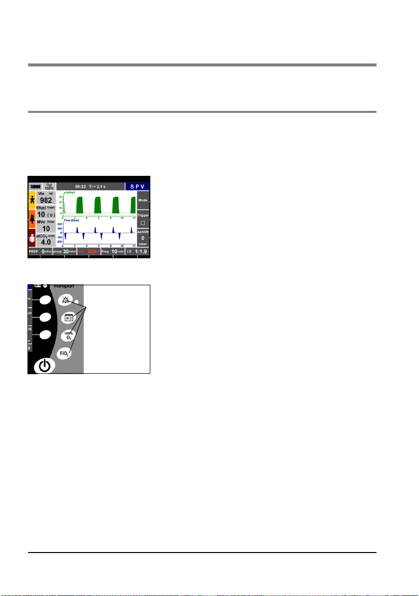
5.8 Other ventilation functions
The ventilation functions “O2 concentration“ and “100% O2“ are available for all the
ventilation modes. You can call up and set these functions at any time using the fixedassignment function buttons on the right of the display.
Warning!
Risk of poisoning! Highly concentrated oxygen can have a toxic effect on the patient
if administered for too long and depending on the patient's age. When ventilating
with pure oxygen or an oxygen-air mixture, make sure that oxygen is only administered for an appropriate period.
Setting the O2 concentration
To save oxygen, ventilation is normally carried out with an oxygen/air mixture. The administered oxygen concentration can be selected between 40% and 100%. The currently measured value is shown in the top info field on the display.
If you switch from oxygen/air mixture (40% O
minute volume changes within the preset tolerances (see 12. “Technical Data”on
page 95), at the most. To set the O
concentration, proceed as follows.
2
1. Call up the “O
button.
) to pure oxygen (100% O2), the respiratory
2
concentration“ menu using the FiO2
2
46 Operation
2. Select “O2 concentration“ in the menu and confirm
your selection.
3. Select the required O2 concentration using the
navigation knob or the function buttons.
4. Press the button or the navigation knob to confirm
your selection.
Page 47

100% O2 function
To raise the oxygen concentration to 100% (for a maximum of two minutes), you can use
the “100% O
“ function.
2
1. Press the “100% O2“ button to confirm the function.
The message “100% O2“ appears on the display.
2. Press the “100% O
Ventilation is continued with the originally set O
“ button again to end the function.
2
con-
2
centration. The function is ended automatically after
two minutes.
Operation 47
Page 48

5.9 Performing ventilation
Tube
As a rule, the patient is intubated before the tube is connected to the patient valve.
1. Set the desired ventilation mode and the associated ventilation parameters.
2. Attach the patient valve to the connector of the endotracheal tube.
3. During ventilation, check the respiratory parameters on the display. This will enable you
to determine whether ventilation is adequate.
Note
If your unit is equipped with the optional CO
position on the basis of the capnogram and correct it if necessary.
Ventilation mask
1. If necessary, use the elbow supplied with the hose sytem to ensure optimum routing of
the hose system, depending on the patient's position.
Caution
Using the elbow increases the dead space of the hose system. Take this into account
when setting the ventilation parameters. Otherwise the success of treatment may be
compromised.
2. Attach the mask to the hose system.
3. If necessary, introduce a Guedel oropharyngeal tube to keep the patient’s airways free.
4. Place the ventilation mask over the patient's mouth and nose.
5. Extend the patient's head and, at the same time, hold the mask tight against the
patient's face by means of the EC grip.
measurement, you can check the tube
2
48 Operation
Page 49

5.10 Monitoring ventilation
General
During ventilation, you must monitor the patient continuously. You can follow the progress
of ventilation on the display. You can select various display formats.
High airway resistances, e.g., due to obstructions of the airway or during external cardiac
massage, may change the respiratory minute volume, depending on the ventilation mode.
If lung compliance decreases, the unit responds as follows:
• With volume-controlled ventilation, the ventilation pressure rises until
the set pressure limit is reached, while the ventilation volume remains
constant. Then the applied volume drops.
• With pressure-contolled ventilation, the applied volume drops while the
pressure remains constant.
Example of ventilation progression before and after
decrease in compliance during volume-controlled
ventilation
Note
All the displayed measurements for flow, volume, or MV relate to ambient
temperture and ambient air pressure.
Operation 49
Page 50

Displayed measurements
During ventilation, the following parameters are shown on
the display as numbers:
Ventilation progress graphs
For the purpose of ventilation monitoring, the standard
unit displays the following parameters:
If you have a unit equipped with CO2 measurement, you
can display up to three graphs. The following presentaion
versions are possible:
–V
: expiratory tidal volume
te
– f(fsp): respiratory rate/number of spontaneous
breaths per minute
: expiratory minute volume
–MV
e
–etCO
–O
: end-tidal CO2 concentration (only with
2
units equipped with optional CO
i: inspiratory O2 concentration delivered by the
2
measurement)
2
unit
– Ventilation pressure, flow
– Ventilation pressure, flow
– Ventilation pressure, CO
– Ventilation pressure, flow, CO
2
2
50 Operation
Page 51

5.11 Alarm signals
Alarm priority
MEDUMAT Transport classifies alarms in the following priority levels:
• high priority
• medium priority
• low priority
If two or more alarms occur simultaneously, alarms with the currently highest priority are
displayed cyclically.
You can set limit values for alarms relating to respiratory physiology (see 6.2 “Setting alarm
limits”on page 61).
Display of alarms
MEDUMAT Transport displays alarms as follows:
• High priority
– LED flashes red
– Audible alarm “high priority“ every 8 seconds
– Alarm text appears in info field; info field flashes
Info field
red
• Medium priority
– LED off
– Audible alarm “medium priority“ every 15 seconds
– Alarm text appears in info field; info field flashes
yellow
• Low priority
– LED off
– Audible alarm “low priority“ every 30 seconds
– Alarm text appears in info field; info field has
turquoise background
Operation 51
Page 52

Muting the alarm
When an alarm occurs, you can mute the audible alarm
temporarily (120 seconds) by pressing the Alarm Mute
button. For these 120 seconds, a yellow LED is alight. Press
the button again to reactivate the acoustic alarm. The
visual alarm remains active.
As soon as a higher-priority alarm occurs, the acoustic
alarm is immediately reactivated.
Visual and acoustic alarms are automatically reset as soon
as the cause of the alarm has been rectified.
5.12 Ventilation with filters (not supplied with the unit)
For hygiene purposes, and to condition the air for breathing, you can equip the patient
valve with commercially available filters (HME, bacterial or combined HME/bacterial filters)
with standard 15/22 mm connections. This increases both the inspiration and expiration
resistance, so you should monitor the ventilation pressure and volume with special care.
Allowance must be made for the larger dead space, especially with children.
Always follow the filter manufacturer's operating instructions.
5.13 Ending ventilation
Caution!
Never empty the oxygen cylinder completely. Always ensure that there is a certain
residual pressure in the cylinder when you return it for filling, as this prevents moist
ambient air from entering and causing corrosion.
1. Check the remaining oxygen content on the contents gauge. If the contents gauge
indicates 50 bar or less, the cylinder must be refilled or a reserve cylinder obtained to
ensure that the unit remains ready for use.
2. Close the valve on the oxygen cylinder.
52 Operation
Page 53

3. Hold down the On/Standby/Off button for 2 seconds to
switch the unit to standby.
Note:
The unit still uses up electricity in standby mode. If the unit does not need to be used
for a long time or is not connected to the power supply, we recommend switching
it off. To do so, hold down the On/Standby/Off until the LED alarm goes out (approx.
10 seconds ).
5.14 Calculating the oxygen level/operating time
Caution!
When calculating the oxygen level in the cylinder, take into account the unit's
O
consumption (see 12.4 “O2 consumption of the unit”on page 100). Otherwise
2
you may miscalculate how long the cylinder will last, which may impair the success
of treatment.
Oxygen level in the cylinder
Oxygen volume = cylinder volume x cylinder pressure.
Cylinder volume x Cylinder pressure = Oxygen content
Example 1
Example 2
10 l x 200 bar = 2000 l
10 l x 100 bar = 1000 l
Available operating time for ventilation
Vt (tidal volume) x f (respiratory rate)= MV (minute volume)
Oxygen content (l)
Available operating time for ventilation (min)
------------------------------------------------------------- - -
Vt x f + O2 consumption
Example 1:
O
supply = 1000 l; Vt x f = 11 l/min; 100% O2, O2 consumption 0.3 l (see 12.4 “O2 con-
2
sumption of the unit”on page 100).
100
--------------------------------------------
×=
O2 concentration
Operation 53
Page 54

This gives: 3
Available operating time for ventilation (min)
1000 l
------------------------- -
11.3 l/min
100
--------------- -
× 88 min 1h 28 min===
100%
If MEDUMAT Transport is operated with an O2 concentration less than 100%, the operating
time will increase correspondingly.
54 Operation
Page 55

5.15 Alternative ventilation
In the event of the MEDUMAT Transport breaking down during ventilation, you have the
following alternatives:
Ventilation bag
1. Pull the patient valve off the tube or mask.
2. Attach the ventilation bag, e.g., COMBIBAG WM 11000 from WEINMANN and carry
out manual ventilation.
Ventilation aid
You can use the LIFEWAY WM 10580 from WEINMANN to perform mouth-mask
ventilation.
Oxygen failure
In exceptional situations, when there is no oxygen supply, the MEDUMAT Transport can
also be operated with sterile compressed air.
Note
During ventilation with sterile compressed air or concentrator oxygen, the unit gives
the “
O
↓“ alarm continuously.
2
5.16 Changing battery during use
The battery should be changed in good time when it starts to run low. Always keep a fully
charged battey ready for changeover.
Note
If you change the battery within the space of 30 seconds, the unit restarts
automatically. Settings made before changing battery are then retained.
Proceed as follows:
1. Have the fully charged battery ready to hand.
2. Pull the low battery out of the unit's battery compartment.
3. Insert the replacement battery into the compartment within 30 seconds.
4. Continue with ventilation.
Operation 55
Page 56

5.17 Battery management
MEDUMAT Transport has an internal power supply with a rechargeable battery.
Two battery versions are available:
• Battery pack Plus WM 28385 for internal and external charging; can be
recharged either in the unit or using an external charger WM 28390;
charge level can be checked on the battery.
• Battery pack WM 28384 for internal charging; can only be recharged in
the unit; charge level can be checked on the battery.
For recharging, an external DC power supply with 12 – 15 V (internal charging) or 15V
(external charging) is required. Only use the vehicle/aircraft electrical power supply. If
charging in an AC wall outlet, use the charger WM 28390.
MEDUMAT Transport can be operated from an external power supply when the battery is
empty. The battery is charged while the unit is in operation, but charging takes longer than
when the unit is off.
Caution!
• The unit must never be operated without the battery installed because any
voltage dips in the power supply cannot then be bridged, which would mean
that uninterrupted ventilation of the patient is not guaranteed.
• Battery-operated medical devices have a limited operating period.
MEDUMAT Transport can be operated for at least three hours without
an external power supply, provided that the battery is fully charged. You
should therefore ensure that the battery is always as fully charged as possible, or have a spare battery ready for use.
Battery charge level indicator (MEDUMAT Transport)
At the top left of the display you will find the symbol indicating the battery charge level. The indication is in five
stages. The picture opposite shows examples of a full, half-
empty
56 Operation
fullhalf-full
full and empty battery.
Page 57

Charge level indicaton on the battery itself
When the battery is removed from the unit, you can check
the charge level on the battery itself. The state of charge is
indicated by 4 green LEDs. Press the button on the battery
(see drawings opposite).
Charge level
indicator
Battery charge level
4 LEDs 100%
3 LEDs 75%
2 LEDs 50%
Charge
indicator
Button
Status LED
1 LED 25%
1 LED flashing less than 10 minutes charge left
The battery's state of charge is indicated by the status LED
Status LED Battery
LED glows green Battery fully charged
LED flashes green Battery is being charged
Accu-Pack Plus
MEDUMAT Transport
WM 28385
LED glows red Battery defective. Do not use.
Charging status indicator
The charging status is only indicated when the external power supply is connected, as only
then is it possible to charge the battery.
When MEDUMAT Transport is off, the charging status is shown by the charging indicator.
When MEDUMAT Transport is on, both the charging status and the battery's charge level
are indicated.
Key to charging status and charge level indicators:
Unit off Unit on
Battery charging
Battery full
Charging
indicator
flashes green flashes green
green green
Charging indicator Charge level indicator
(current charge status)
(full)
Operation 57
Page 58

Unit off Unit on
Problem during
charging
Battery is being
discharged
Battery missing or
defective
red red
off off
off red
Charging batteries
MEDUMAT Transport starts charging the battery
conditions are met:
• External power supply with at least 12 V DC
connected
• The battery is not full (<95% charge)
• Battery temperature not above 45°C or
below +5°C
Note
The battery WM 28385 has its own charging interface,
so it can also be charged outside the
Charging indicator
Transport. Only use the charger WM 28390.
If charging cannot be started, e.g., because the battery
temperature is outside the permitted range (+ 5°C 45°C), the charging indicator glows red. It only goes
out once all the conditions for starting charging are
met.
While the battery is being charged, the charging indicator
flashes green.
(current charge status)
(current charge status)
(current charge status)
automatically as soon as the following
MEDUMAT
Ending battery charging
MEDUMAT Transport automatically determines the optimum point at which to end charging by measuring and evaluating the charging curve and battery temperature. As soon as
charging has ended, the charging indicator glows steady green.
58 Operation
Page 59

Interrupting battery charging
Battery charging is continuously monitored by MEDUMAT Transport.
Problems which lead to charging being interrupted are:
• Battery temperature rises above 45°C, e.g., due to high ambient temperature,
or falls below +5°C
• Charging current is too high (>3 A) e.g., short-circuit
If one of these problems occurs, charging is automatically interrupted and the charging
indicator glows red.
Charging is also interrupted if there is no external power supply, e.g., because the unit,
mounted on a portable system, has been removed from the wall mounting. The charging
indicator does not light up in this case because this is not a fault, but a normal operating
state. As soon as the external power is restored, e.g., when the portable system is replaced
in the wall mounting, charging continues.
Operation 59
Page 60

6. Configuring the unit
In the main menu, you can optimize the unit's settings to
suit the particular service conditions. The main menu can
be called up at any time using the function button for
“Main menu”.
To navigate in the menu, you can use either the navigation
knob or the context-dependent function buttons on the
right of the display (see “5.1 Controls” on page 28).
6.1 Automatic alarm limits
General
When the “Automatic alarm limits“ function is active, the unit automatically sets limits for
the alarms relating to respiratory physiology. The determining factor for setting the limits
is the respiratory values (V
when the function is activated.
In the “Alarm limits“ menu (see “6.2 Setting alarm limits” on page 61), you can set the
size of deviation (in %) from the current respiratory value at which an alarm is triggered.
To activate the “Automatic alarm limits“ function, proceed as follows:
, MVe, f, and, if applicable, etCO2) measured at the moment
te
60 Configuring the unit
1. Press the function button for “Main menu” to call up
the main menu.
2. Select “Automatic alarm limits“ in the menu and
confirm your selection.
3. Select “Yes“ in the menu and confirm your selection.
Note
The values set for “Alarm limits“ (see “6.2 Setting
alarm limits” on page 61) are overwritten.
Page 61

Automatic alarm calculation for the Apnea alarm
The Apnea alarm is set, depending on the percentage, to 4 (10%), 5 (20%) or 6 (30%)
respiratory periods. The length of a respiratory period is 60/f in seconds, i.e., with a
measured respiratory rate of, for example, 15/min, the steps for the Apnea alarm limit are
16 s, 20 s, and 24 s.
Automatic alarm for the CO2i high alarm
If the Automatic alarm limits are activated, the limit for the CO2i alarm is automatically set
at 5 mmHG.
6.2 Setting alarm limits
You can set limit values for alarms relating to respiratory
physiology. Proceed as follows:
1. Press the function button for “Main menu” to call up
the main menu.
2. Select “Alarm limits“ in the menu.
3. Select the alarm for which you wish to change the limit
values, and confirm your selection.
4. Set the limit value and confirm your setting.
5. Repeat steps 3. and 4. for all the alarms whose limit
values you wish to change.
6. To exit the menu, select “Back“ in the menu and
confirm your selection.
You can set limit values for the following alarms.
Alarm Setting range
Auto alarm limits
V
high 55 - 3000 ml
te
low 5 - 2000 ml
V
te
MV high 1 -160 l
MV low 0.1 - 110 l
f high 1 - 150/min
Apnea 4 - 60 s
10%, 20%, or 30% of the respiratory
values at the time of activation
Configuring the unit 61
Page 62

Alarm Setting range
etCO2 high
et CO
low 0 - 40 mmHg/ 0-9.9% by vol./0-5.4 hPa
2
CO
i high 5 - 7 mm Hg / 0-9.9% by vol. / 0-10 hPa
2
20 - 75 mmHg/ 2.6-9.9% by vol./
2.6-10 hPa
6.3 Setting the presentation of ventilation values (only with units with etCO2 measurement)
For the purpose of ventilation monitoring, you can have up to three parameters (ventilation
pressure, flow, CO
MEDUMAT Transport with etCO
possible:
concentration) simultaneously, in graph form, on the display of the
2
measurement. The following presentation versions are
2
– Ventilation pressure, flow
– Ventilation pressure, CO
– Ventilation pressure, flow, CO
2
2
To select a presentation version, proceed as follows:
1. Press the function button for “Main menu” to call up
the main menu.
2. Select “Curves“ in the menu.
3. Select the presentation version you require and confirm
your selection.
4. To exit the menu, select “Back“ and confirm your
selection.
62 Configuring the unit
Note
On units without etCO
measurement the display
2
shows respiratory pressure and flow as graphs. No
other settings are possible.
Page 63

6.4 Setting advanced respiratory parameters
To achieve optimal results during transport ventilation, you
can make settings in the “Advanced ventilation
parameters“ menu, depending on the selected mode.
The non-selectable functions in a particular ventilation
mode are shown in grey letters.
Setting the pressure ramp
With this function you can set how fast the inspiratory
ventilation pressure is reached. The following rise times are
possible:
• Flat ramp: slow pressure rise
• Medium ramp: medium pressure rise
• Steep ramp: fast pressure rise
Note
How quickly the set pressure is actually reached
depends on the patient, any leakage (NIV) and the
ventilating parameters that have been set.
To set the pressure ramp, proceed as follows:
1. Press the function button for “Main menu” to call up
the main menu.
2. Select “Advanced ventilation parameters“ in the menu
and confirm your selection.
3. Select “Pressure ramp“ in the menu and confirm your
selection.
4. Select the level (1-3) you require and confirm your
selection.
5. To exit the menu, select “Back“ and confirm your
selection.
Configuring the unit 63
Page 64

Setting the flow ramp
With this function you can set how fast the inspiratory
flow is reached. The following rise times are possible:
• Flat ramp: slow flow rise
• Medium ramp: medium flow rise
• Steep ramp: fast flow rise
Note
How quickly the set flow is actually reached depends on
the patient, any leakage (NIV) and the ventilating
parameters that have been set.
To set the flow ramp, proceed as follows:
1. Press the function button for “Main menu” to call up
the main menu.
2. Select “Advanced ventilation parameters“ in the menu
and confirm your selection.
3. Select “Flow ramp“ in the menu and confirm your
selection.
4. Select the level you require and confirm your selection.
5. To exit the menu, select “Back“ and confirm your
selection.
64 Configuring the unit
Page 65

Flow progress
Setting trigger thresholds
With this function you can set the flow progress. Proceed
as follows:
1. Press the function button for “Main menu” to call up
the main menu.
2. Select “Advanced ventilation parameters“ in the menu
and confirm your selection.
3. Select the setting you require under “Flow progress“
(“constant“ or “decreasing“) and confirm your
selection.
4. To exit the menu, select “Back“ and confirm your
selection.
With this function you can set the inspiratory and
expiratory trigger threshold. Proceed as follows:
1. Press the function button for “Main menu” to call up
the main menu.
2. Select “Advanced ventilation parameters“ in the menu
and confirm your selection.
3. Under “Trigger thresholds“, select “Inspiration“ or
“Expiration“ and confirm your selection.
4. Set the value you require and confirm your setting.
5. To exit the menu, select “Back“ and confirm your
selection.
You can make the following trigger settings:
Trigger Setting range
Inspiration 1 - 15 l/min in 1-liter steps
Expiration
5%-50% of the maximum flow
in 5% steps
Configuring the unit 65
Page 66

6.5 “Night colors“ display mode
To ensure optimal legibility in night-time use, you can
activate the “Night colors“ display mode. In this mode, the
display has a black background to prevent glare.
To activate the “Night colors“ display mode, proceed as
follows.
1. Press the function button for “Main menu” to call up
the main menu.
2. Select “Night colors“ in the menu.
3. Press the navigation knob or the button to activate
the “Night colors“ display mode. To deactivate the
mode, press the navigation knob or the button
again.
4. To exit the menu, select “Back“ and confirm your
selection.
66 Configuring the unit
Page 67

6.6 Setting the display brightness and the volume
In the Audio/Video menu, you can set the display
brightness separately for day and night colors. You can
also set the alarm volume. Proceed as follows:
Setting the brightness
1. Press the function button for “Main menu” to call up
the main menu.
2. Select “Audio/Video“ in the menu and confirm your
selection.
3. Select “Brightness/Day“ or “Brightness/Night“ and
confirm your selection.
4. Select the setting you require (10% - 100%) and
confirm your selection.
5. To exit the menu, select “Back“ and confirm your
selection.
Setting the volume
1. Press the function button for “Main menu” to call up
the main menu.
2. Select “Audio/Video“ in the menu and confirm your
selection.
3. Under “Volume“, select the setting you require (50% 100%) and confirm your selection.
4. To exit the menu, select “Back“ and confirm your
selection.
Configuring the unit 67
Page 68

6.7 Options
CO2 configuration
Setting the date and time
In the “CO2 configuration“ menu, you can select which
unit of measurement the CO
in. Proceed as follows:
1. Press the function button for “Main menu” to call up
the main menu.
2. Select “Options“ in the menu and confirm your
selection.
3. Select “CO
4. Select the unit you require (mmHg, % by vol., kPa) and
confirm your selection.
5. To exit the menu, select “Back“ and confirm your
selection.
In the “Date, time“ menu, you can set the current date
and time. Proceed as follows:
1. Press the function button for “Main menu” to call up
the main menu.
2. Select “Options“ in the menu and confirm your
selection.
3. Select “Date, time“ and confirm your selection.
4. Set the year, month, date, hour, minute, and confirm
your selection.
5. To exit the menu, select "Back" and confirm your
selection.
configuration“ and confirm your selection.
2
concentration is displayed
2
68 Configuring the unit
Note
The date and time are also used for the unit's internal
operations. Therefore they should both be checked
regularly and corrected if necessary.
Page 69

Selecting the display language
1. Press the function button for “Main menu” to call up
the main menu.
2. Select “Options“ in the menu and confirm your
selection.
3. Select “Language“ and confirm your selection.
4. Select the language you require in the “Language“
menu and confirm your selection.
5. To exit the menu, select “Back“ and confirm your
selection.
Calling up the unit data
1. Press the function button for “Main menu” to call up
the main menu.
2. Select “Options“ in the menu and confirm your
selection.
3. Select “Device data“ and confirm your selection.
4. To exit the menu, select “Back“ and confirm your
selection.
Configuring the unit 69
Page 70

7. Hygienic preparation
The MEDUMAT Transport and the accessories used must be hygienically prepared after
each use. Please refer to the instructions supplied with the disinfectant used. We recommend using GIGASEPT FF for immersion disinfection and TERRALIN for wipe disinfection.
Always carry out a functional check after the hygienic preparation (see “8. Function check”
on page 74).
7.1 MEDUMAT Transport
MEDUMAT Transport and the BiCheck flow sensor lead should be kept clean by simple
wipe disinfection.
Please refer to the instructions supplied with the disinfectant used. We recommend using
TERRALIN for wipe disinfection.
Warning!
Never immerse the MEDUMAT Transport or the BiCheck flow sensor lead in
disinfectant or other liquids. Otherwise the unit may be damaged, causing a hazard
to users and patients.
7.2 Hose systems
The measuring components (connector, PEEP control lead, pressure-measurement tube,
CO
removal tube with water filter) of the reusable hose system cannot be reused.
2
For preparing the other components, follow the operating instructions supplied with the
hose systems.
70 Hygienic preparation
Page 71

7.3 Parts and accessories
Masks and all silicone parts must be cleaned in a disinfectant solution:
1. All surfaces must be wetted, free of bubbles, inside and outside. Allow the disinfectant
to act for the full time specified by the manufacturer.
2. After disinfection, rinse the parts thoroughly with distilled water to avoid residues of the
disinfectant solution causing problems.
3. Leave all silicone parts to dry in the air.
4. Visually inspect the masks, and replace any damaged parts immediately.
The reusable ventilation tube, reusable patient valve (see previous section), reusable
BiCheck flow sensor and ventilation masks with silicone cushion can also be autoclaved.
7.4 Fittings
Warning!
Risk of explosion! Never immerse the fittings in disinfectant or other liquids. Only
carry out wipe disenfection. Liquid must not be allowed to enter the pressure
reducer. Otherwise there is a risk of explosion.
If it is absolutely necessary to clean the fittings (e.g., pressure reducer, valve), use a clean
cloth. The cloth may be dry or moistened with clean water.
Hygienic preparation 71
Page 72

7.5 Cleaning, disinfection and sterilization
Carry out hygienic preparation of the MEDUMAT Transport and the accessories used, as
described in the following table.
Refer to the instructions supplied with the hose system and with the disinfectant used. We
recommend using GIGASEPT FF for immersion disinfection and TERRALIN for wipe disinfection. You are advised to use suitable gloves for disinfection work (e.g., household or disposable gloves).
Reusable components
Parts Cleaning Disinfection
MEDUMAT Transport
BiCheck flow sensor lead
BiCheck flow sensor
Reusable patient valve
Reusable ventilation
mask
Reusable ventilation hose
Reusable tube protection
sleeve
Oxygen fittings
Wipe down with a
moist cloth
Wipe down with a
moist cloth
In hot water with a
mild household
detergent
In hot water with a
mild household
detergent
Wipe down with a
moist cloth
With a dry or moist
cloth
(1) After disinfection, rinse the parts thoroughly with distilled
water, and leave them to dry.
(2) Thermal disinfection in a washer
(3) Superheated steam sterilization at 134°C with devices which
comply with EN 285; holding time up to 18 minutes.
Thermo-
disinfector
Wipe disinfection Not permitted
Wipe disinfection Not permitted
Clean at 65°C, as
Immersion
disinfection
Immerse in 6%
GIGASEPT FF
(1)
solution
30°C washing
cycle, without
spinning
Wipe disinfection Not permitted
instructed in the
(1)
disinfector manual.
Dry thoroughly
Washing cycle up to
95°C
Possible during the
(2)
washing cycle
Steriliza-
tion
Not
permitted
Not
permitted
Superheated
steam sterilization at
up to
(3)
134°C
Superheated
steam sterilization at
up to
(3)
134°C
Not
permitted
Not
permitted
72 Hygienic preparation
Page 73

Disposable components
Parts Cleaning Disinfection
Measurement hose
system comprising:
– PEEP control line
– Pressure-measurement
tube
–CO
removal tube
2
– Connector
– Water filter
Dispoable Patient Hose
System
Thermo-
disinfector
These are disposable parts and must not be reused. Use new parts instead.
Steriliza-
tion
Hygienic preparation 73
Page 74

8. Function check
The user must carry out a function check on the unit before each use and after each
disassembly, but at least every 6 months.
• Connect the ventilation hose, the patient valve, and a test bag to the
MEDUMAT Transport.
Warning!
If this function check reveals any faults or discrepancies compared to the specified
values, you must not use the MEDUMAT Transport. Have the unit repaired by
WEINMANN or an authorized dealer.
You should first try to rectify the fault with the aid of the information provided in Section
“9. Troubleshooting” on page 80. If this is not possible, have the unit repaired by the
manufacturer, WEINMANN, or by a technician expressly authorized by WEINMANN.
A full function check comprises:
• Visual inspection for mechanical damage
• Visual inspection of the display
• “8.2 Checking the system for leaks” on page 75
• “8.3 Checking the patient valve (only reusable hose system)” on page 77
• “8.4 Automatic function check” on page 77
• We recommend you to always keep the following spare parts available:
– Spare seals for the unit connections
– A replacement dust filter
– PEEP control diaphragm for patient valve
– Check valve diaphragm for patient valve
– Measurement hose system, including water filter, for
measurement
CO
2
Note
Make sure that the test bag has been serviced in accordance with the maintenance
schedule.
74 Function check
Page 75

8.1 Intervals
Before each use:
• Perform a function check.
After each use or disassembly:
• Clean, disinfect and sterilize the unit (see “7. Hygienic preparation” on
page 70)
• Perform a function check
At least every 6 months:
• Perform a function check.
• Check the suction filter for soiling. Unscrew and remove the filter cover.
Never reinstall used filters.
8.2 Checking the system for leaks
1. Slowly open the valve on the oxygen cylinder. You can
now read the cylinder pressure on the contents gauge
of the pressure reducer. For example, a reading of 200
bar means that the cylinder is full, a reading of 100 bar
that it is half full.
You should change the cylinder in good time, e.g.
when the pressure falls below 50 bar, to ensure a
sufficiently long operating time.
2. Close the cylinder valve again.
3. Observe the needle of the contents gauge on the
pressure reducer for approx. 1 minute. If the position of
the needle stays constant, the system is free from leaks.
If the needle falls steadily, there is a leak in the system.
Function check 75
Page 76

Rectifying leaks
Note
Always keep a stock of replacement seals for the connections.
1. Prepare a soapy solution using unperfumed soap.
2. Wet all the screw and hose connections with the solution. If bubbles form, this indicates
a leak.
3. Release the pressure in the system:
Close the oxygen cylinder valve. Switch MEDUMAT Transport on briefly until the
contents gauge on the O
off again.
Caution!
The screwed unions of the oxygen lines must only be tightened by hand.
4. If there is a leak, change the defective parts.
5. Then check for leaks again.
6. If the leak cannot be rectified, the unit must be repaired.
cylinder indicates “0“. Then switch MEDUMAT Transport
2
76 Function check
Page 77

8.3 Checking the patient valve (only reusable hose system)
Caution!
• Also observe the “Functional control“ section in the instruction manual of the
“Patient Hose System“ WM 66696.
• Never use torn, wavy, distorted or sticky diaphragms for ventilation. Otherwise
considerable malfunctions are to be expected.
• When assembling the patient valve, it is essential to make sure that the diaphragm
is correctly positioned and the right way up (the letters TOP on the PEEP control
diaphragm must face upwards). Otherwise the patient valve may malfunction,
putting the patient at risk.
1
45
3. Visually inspect all parts for cracks or other mechanical damage.
4. Change any diaphragms that are torn, wavy, distorted or sticky.
5. Reassemble the patient valve.
1. Pull all the tubes and cables off the patient valve.
2. Dismantle the patient valve.
2
– 1 Control cover
– 2 PEEP control diaphragm
3
– 3 Main body of the patient valve
– 4 Check valve diaphragm
– 5 Holder for the check valve diaphragm
8.4 Automatic function check
MEDUMAT Transport has an automatic function check feature for testing the unit's
sensors, actuators and controls. To start the automatic function check, proceed as follows.
Start automatic function check
1. First, assemble MEDUMAT Transport ready for
operation with Patient Hose System.
Function check 77
Page 78

2. Switch the unit on.
3. Check that, during the self-test, the alarm LED lights up
briefly.
4. Check that, during the self-test, the alarm buzzer emits
a series of five audible sounds and that the loudspeaker
then emits two audible sounds.
5. Select the “Function check“ item on the start screen
6. Follow the instructions on the display.
– Check for leaks (see “8.2 Checking the system for
leaks” on page 75) and check the hose system (see
“8.3 Checking the patient valve (only reusable
hose system)” on page 77)
– Open the valve of the oxygen cylinder
– Connect the patient hose system
– Connect a testing bag. Do not touch the patient’s
hose and the testing bag after this
Note:
If a fault in the unit occurs during the function check, inspect the hose system and
the testing bag. Switch the unit off and then on again. Repeat the function check.
If the fault reoccurs, have the unit repaired by WEINMANN or an authorized dealer.
Testing the sensors and actuators
1. Start the function check by selecting “Function check“ in the menu.
The automatic function check now runs. This takes approximately one minute. The
unit tests the sensors and actuators. While this is happening, you can start testing the
controls (see “Testing the controls” on page 79).
Do not touch/move the test bag or Patient Hose System. The test bag is filled and
emptied according to a specific pattern during testing, so if it is touched or moved,
the results of the function check could be falsified.
Note
This check ensures that physiological alarms are correctly triggered in the event of a
malfunction during patient ventilation.
78 Function check
Page 79

Testing the controls
While the sensors/actuators are being tested, the function
buttons and control knobs are shown in red on the display.
To check that these controls function correctly, proceed as
follows.
1. Press each of the controls on the unit (Do not press the
controls on the screen), as described in section
“5. Operation“ in this manual.
A control is functioning correctly if the corresponding
control on the screen is shown in green.
If a control is found to have a defect, the corresponding
control on the display is shown in red. In this case,
discontinue the test by pressing the menu button .
Note
Do not press the On/Standby/Off button during the test.
If all the fields are green, a summary is automatically
generated and displayed as soon as the automatic
function check has ended.
2. Confirm the summary with “OK”. The window is
closed.
3. If defects are found in one or more controls
(corresponding fields on the screen are shown in red),
discontinue the test.
Testing the power-failure alarm
1. Once the automatic function check has finished, switch to ventilation mode
2. Pull out the battery and disconnect the charger or remove the portable system from the
wall mounting (for not more than 30 seconds).
If the red alarm LED flashes and an acoustic signal sounds, the power failure alarm is
functional.
3. Reconnect the power supply
4. If you wish to use the unit, switch it on again.
Function check 79
Page 80

9. Troubleshooting
If problems occur which cannot be rectified immediately, contact the manufacturer,
WEINMANN, or your authorized dealer to have the unit repaired. Do not continue using
the unit to avoid serious damage.
9.1 Troubleshooting
Fault Cause Remedy
MEDUMAT Transport
cannot be switched on
Unusually high oxygen
consumption
MEDUMAT Transport
cannot be switched off
Charging indicator glows
red when status button is
pressed.
Battery does not respond
when status button is
pressed.
Unit running time with
battery operation too
short
MEDUMAT Transport defective Repair by manufacturer/dealer.
Battery empty Recharge battery
Leak in the oxygen feed line Locate and rectify leaks (8.2, page 75)
Operating errors
Short-circuit
Battery defective
Battery temperature outside the
permitted range (permitted
range for charging: 5°C - 45°C)
Battery has run down completely
and has shut down to prevent
exhaustive discharge
Battery has reached end of its
service life
Hold down button for at least 2
seconds.
Rectify short-circuit and wait one
minute, then press the status button
again.
Use replacement battery and have
defective battery repaired
Charge battery within permitted
temperature range: Move battery to
cooler or warmer ambient temperature,
as appropriate.
Recharge battery
Use a new battery.
80 Troubleshooting
Page 81

9.2 Physiologic alarms
Message Alarm Cause Rectification
Vte ↑
V
↓
te
MV
↑
e
MV
↓
e
AF
↑
Apnea
Patient-side leak
etCO
↑
2
etCO
↓
2
CO
i ↑
2
O
↑ medium priority
2
O
↓ high priority
2
Vte high
high priority
Vte low
high priority
MVe high
high priority
MVe low
high priority
Hyperventilation
medium priority
Apnea
high priority
Leak
high priority
etCO2 high
high priority
etCO2 low
high priority
CO2i high
high priority
Upper limit value
exceeded
Lower limit value not
reached
Upper limit value
exceeded
Lower limit value not
reached
Limit value exceeded
Limit value exceeded
V
less than 60% V
te
Upper limit value
exceeded
Lower limit value not
reached
Upper limit value
exceeded
Insufficient ambient air
in the respiratory gas
Insufficient O
Leak when NIV option is
deactivated
supply Use medical O2 supply
2
Check state of patient.
Check the limit value settings for
plausibility.
Check state of patient.
Check the limit value settings for
plausibility.
Check state of patient.
Check the limit value settings for
plausibility.
Check state of patient.
Check the limit value settings for
plausibility.
Check state of patient.
Check the limit value settings for
plausibility.
Check state of patient.
Check the limit value settings for
plausibility.
Check hose system and tube; with
mask ventilation, activate NIV
ti
mode.
Check state of patient.
Check the limit value settings for
plausibility.
Check state of patient.
Check the limit value settings for
plausibility.
Check the patient valve.
Check the calibration of the CO
module.
Check parameter setting
Change suction filter
Activate NIV option, thereby
limiting FiO
to 20%.
2
2
Troubleshooting 81
Page 82

Message Alarm Cause Rectification
Airway pressure ↓ high priority
Airway pressure
↑ high priority
Lower limit value not
reached
Patient hose leaking/
slipped off
Tube wrongly
positioned
Hoses kinked
Upper limit value
exceeded
Airway obstruction Check state of patient.
Tube wrongly
positioned
Pmax set tool low Correct Pmax
Hoses kinked
Check state of patient.
Replace patient hose/attach it
correctly
Check position of tube and
correct if necessary.
Check position of hoses and
correct if necessary.
Check state of patient.
Position tube correctly
Check position of hoses and
correct if necessary.
9.3 System alarms
Message Alarm Cause Rectification
Change suction filter on
CO2 occlusion medium priority
CO
module defective low priority
2
CO
module not
2
CO
temperature
2
range not reached
Flow not achievable low priority
ready for
operation
low priority
Suction filter or removal
hose blocked
module defective,
CO
2
no communication or
no plausible data
Temperature in the unit
below 0°C
Implausible settings
(respiratory rate, tidal
volume I:E)
Gas supply inadequate
measurement hose system or
replace complete measurement
hose system
Continue ventilation without CO
measurement; have unit repaired
as quickly as possible.
Continue ventilation without CO
measurement
Provide adequate gas supply,
adjust ventilation parameters
2
2
82 Troubleshooting
Page 83

Message Alarm Cause Rectification
Check BiCheck flow
sensor
Flow module
defective
Input pressure
< 2.7 bar
Input pressure
> 6 bar
Battery operation low priority
No battery or battery
defective
Battery almost empty
Fault when unit is
started
Fault during cylinder/
battery change when
patient is connected
medium priority
medium priority
high priority
high priority
medium priority
A further 10 minutes operation is
possible,
medium priority
high priority Unit defective Have unit repaired
high priority
BiCheck flow sensor
defective or
disconnected
BiCheck flow sensor
connection line
defective or
disconnected
BiCheck module
defective
Compressed gas source
not switched on/oxygen
cylinder almost empty
Compressed gas source
not correctly connected
Compressed gas source
defective
Compressed gas tube
kinked or squashed
Pressure reducer
defective
Pressure of respiratory
gas too high
External power supply
too weak or has failed
No battery inserted Insert battery in unit.
Battery defective Replace battery.
Low battery Use replacement battery.
Fault during the
automatic function
check
Connect BiCheck flow sensor or
use fully functional flow sensor.
Connect BiCheck flow sensor
connection line correctly or use
fully functional sensor lead.
Have unit repaired
Switch on compressed gas source
or use full oxygen cylinder.
Check connection and feed lines
of compressed gas source.
Replace compressed gas source
Route compressed gas tube so
that it is not kinked or squashed.
Replace pressure reducer
Use 6 bar compressed gas source
< or switch unit off and
disconnect.
No unit fault; message appears,
e.g., on removing unit from wall
mounting or portable system or if
a power failure occurs during
operation via the power supply
unit (alarm stops automatically
after 10 seconds).
Disconnect the patient, restart the
unit, repeat the function check.
Troubleshooting 83
Page 84

Message Alarm Cause Rectification
Unit's internal
Unit temperture too
low
Unit temperature high low priority
Unit temperature
critical
Unit too cold
high priority
high priority
temperature < -20°C
Unit switches off after
10 minutes if it is not
warmed up to above
-20°C within this time
Unit's internal
temperature > 65°C
Unit temperature >
+75°C
Unit switches off after
10 minutes, or if its
internal temperature
rises above 82°C
Move unit to a warmer
environment.
Move unit to a cooler
environment. If necessary, switch
unit off to accelerate cooling.
Move unit to a cooler
environment. If necessary, switch
unit off to accelerate cooling.
84 Troubleshooting
Page 85

10. Maintenance
10.1 MEDUMAT Transport
Note:
Remember to always have a safety check carried out after maintenance and repair
work.
MEDUMAT Transport must be serviced at regular intervals.
We recommend that maintenance work such as inspections and repairs should be carried
out by the manufacturer, WEINMANN, or by a technician expressly authorized by
WEINMANN.
Every 6 months
• Change the suction filter (see “10.4 Changing the suction filter” on page 87)
Every 2 years:
Every 2 years, you must have the cleaned and disinfected ventilator and the cleaned and
disinfected reusable hose system subjected to a safety check in accordance with
§6 Medical Device Operator Ordinance (MPBetreibV) (only in the Federal Republic of
Germany) in conjunction with servicing by the manufacturer or by a technician expressly
authorized by the manufacturer
• Check that the equipment is complete;
• Visual inspection:
– mechanical damage
– labeling of the controls
– all external hoses to check for damage
• Check the batteries
• Change wearing parts: e.g., dust filter
• Check system components: portable system, oxygen fittings, hose
connections, etc.
• Check the test bag
• Final inspection according to Inspection and Test Instruction WM 28590
Maintenance 85
Page 86

Every 4 years:
• Servicing of the oxygen fittings (e.g., pressure reducer) by the
manufacturer or by a technician expressly authorized by the
manufacturer.
• Change wearing parts: filter screens
Every 6 years:
• Change wearing parts in the unit, button cell and wearing parts in the
valve seals
Every 10 years:
• Repeat testing of the conventional steel oxygen cylinders by the TÜV
(Technical Inspectorate). The next testing date is shown on the shoulder
of the cylinder.
Every 12 years:
• Change the circuit boards
10.2 Batteries
The batteries used for MEDUMAT Transport are maintenance-free. Nevertheless, it is
advisable to fully charge them at regular intervals (every 6-12 months, depending on the
length of use) and then fully discharge them again.
This so-called “learning cycle“ calibrates the batteries' internal capacity calculation and so
ensures the greatest possible accuracy of charge indication. After the learning cycle, charge
the battery fully again so that it is ready for use.
Note
The batteries used for MEDUMAT Transport do not have a “memory effect“.
Therefore you can recharge them when they are only partially discharged without
reducing their capacity or life. But even these batteries naturally have a limited life of
approx. two years or approx. 300 charging cycles.
10.3 Accessories
Separate maintenance intervals and maintenance volumes apply for the accessories to
MEDUMAT Transport. Please observe the respective instructions for use.
86 Maintenance
Page 87

Oxygen cylinders must be re-examined on a regular basis. The due date can be found on
the corresponding label on the cylinder.
10.4 Changing the suction filter
Caution!
Never operate the unit without the suction filter. Otherwise the unit's functions may
be impaired or the unit may be damaged.
1. Undo the two screws in the filter compartment cover
(hexagon socket head screws, 3 mm) and remove the
cover.
Note
Support the cover on one side with a slot-head
screwdriver. This prevents the cover from jamming
while you are lifting it off.
Filter
Screws
Filter compartment
cover
4. Wipe disinfect the filter compartment cover with Terralin and let it dry.
5. Install the new suction filter with tweezers so that the letters “top“ remain visible when
the filter is in place.
6. Refit the cover and screw tight.
2. Remove the old filter with tweezers.
3. Clean the area of the air inlet and outlet openings with
a cotton bud (moistened with Terralin).
Caution!
Do not use compressed air for cleaning the area of
the air inlet and outlet openings, as this may blow
dust particles into the unit. This can cause
malfunctions, thereby putting the patient at risk.
Maintenance 87
Page 88

10.5 Storage
If MEDUMAT Transport is not going be used for a considerable length of time, we
recommend the following procedure:
1. Clean and disinfect the unit (see “7. Hygienic preparation” on page 70).
2. Switch the unit off by pressing the On/Standby/Off button (approx. 10 seconds) until the
alarm LED goes out completely.
3. Store MEDUMAT Transport in a dry place (see “12. Technical Data” on page 95).
Caution!
Be sure to observe the maintenance intervals even when the unit is in storage, as
otherwise it must not be used when removed from storage.
Note
If the unit is going to be stored for longer than a month, remove the battery and store
separately. To keep the battery ready for use, charge it every six months.
10.6 Disposal
Ventilator
Do not dispose of the unit in the household waste. Consult
an authorized electronic waste recycling company for the
proper disposal of the unit. You can find out their address
from your environmental officer or from your local council.
Disposal of batteries
88 Maintenance
Do not dispose of used batteries in the household waste.
Contact WEINMANN or a public waste disposal authority.
Page 89

11. Product, accessories
11.1 Standard scope of supply
MEDUMAT Transport WM 28300
Parts Order number
MEDUMAT Transport basic unit WM 28315
Reusable patient hose system, complete WM 28425
Battery WM 28384
Set of vibration absorbers for unit installation WM 15730
Ventilation mask size 5 for adults WM 5074
Set of CPAP/NIV disposable masks with air cushion
– 1 x CPAP/NIV disposable mask in each of the
sizes S, M, L with retaining ring for headgear
– 1 x headgear
Set for unit inspection of MEDUMAT Transport WM 15737
Set of suction filters WM 15473
Form for STK (safety check) certificate (Germany
only)
Delivery record WM 16318
Medical device book WM 16212
Instruction manual MEDUMAT Transport WM 66001
Concise operating instructions WM 66016
WM 15807
WM 28325
MEDUMAT Transport with CO
Parts Order number
MEDUMAT Transport basic unit with CO
Other items supplied as with MEDUMAT Transport
WM 28300
module WM 28400
2
module WM 28415
2
Product, accessories 89
Page 90

11.2 Accessories
Parts Order number
Oxygen cylinder, 2-liter WM 1822
Lightweight aluminium oxygen cylinder, 2-liter WM 1821
Pressure reducer OXYWAY Fix III 120 l/min; 4.5 bar WM 30301
Pressure reducer OXYWAY Fast II High Flow
190 l/min; 4.5 bar
Water trap WM 28360
Pressure hose, 10 bar, with connection nozzle G 3/
8; at the other end, the option of a union nut G 3/8
or oxygen supply connector
Pressure hose, fabric, 3000 mm LG WM 13260
Vibration absorber WM 15730
Externally chargeable battery WM 28385
Power supply unit WM 28390
Set, holding plate for equipment rail WM 15845
Set, wall holder for power supply unit and charger WM 15846
Wall holder for rechargeable battery pack WM 15847
Hospital standard rail attachment set
(1 x WM 8244)
Rail bracket attachment set WM 15806
12 V supply lead WM 28356
Ventilation mask, transparent, with inflatable
silicone cushion:
– Adults - Size 5
– Children and teenagers - Size 3
– Babies and infants - Size 1
Ventilation mask, one-piece, silicone
–Size 5
–Size 4
–Size 2
–Size 1
–Size 0
WM 31891
Article number
on request
WM 15795
WM 5074
WM 5082
WM 5086
WM 5084
WM 5085
WM 5092
WM 5091
WM 5090
90 Product, accessories
Page 91

Parts Order number
Rendell-Baker ventilation mask, silicone:
– Children - Size 3
– Children - Size 2
– Infants - Size 1
– Babies - Size 0
WM 5063
WM 5062
WM 5061
WM 5060
CPAP/NIV reusable mask, silicone
– Children - Size S
– Adult - Size M
– Large adult- Size L
WM 20713
WM 20714
WM 20715
Set of ventilation masks, silicone
– 1 x CPAP/NIV reusable mask in each of the sizes
S, M, L
WM 15808
– 1 x headgear
– 1 x retaining ring for headgear
Retaining ring for headgear for CPAP/NIV reusable
masks
WM 20701
Oropharyngeal tube:
– Adults - Size 3
– Teenagers - Size 2
– Children - Size 1
WM 3165
WM 3163
WM 3162
Reusable patient hose system, 3 m, complete WM 28676
Disposable hose system, 3 m, with CO
measurement, without BiCheck flow sensor
Disposable hose system, 3 m, without CO
measurement, without BiCheck flow sensor
Measurement hose system, 3 m, without CO
measurement, packaged
Set of disposable hose systems, 3 m, with CO
measurement, without BiCheck flow sensor
2
2
2
2
WM 28688
WM 28691
WM 28693
WM 15851
(10 x WM 28690)
CO
measurement, without BiCheck flow sensor
2
(10 x WM 28690)
Set of measurement hose systems, 3 m, with CO
measurement (10 x WM 28595)
WM 15852
2
WM 15853
Product, accessories 91
Page 92

Parts Order number
Set of measurement hose systems, 3 m, without
CO
measurement (10 x WM 28685)
2
Disposable hose system, without CO
2
measurement, with BiCheck flow sensor
Disposable hose system, with CO
measurement,
2
with BiCheck flow sensor
Measurement hose system, without CO
2
measurement, without BiCheck flow sensor
Set of disposable hose systems, with CO
2
measurement, without BiCheck flow sensor
(10 x WM 28690)
Set of disposable hose systems, with CO
2
measurement, without BiCheck flow sensor
(25 x WM 28690)
Set of disposable hose systems, with CO
2
measurement, without BiCheck flow sensor
(50 x WM 28690)
Set of disposable hose systems, without CO
2
measurement, without BiCheck flow sensor
(10 x WM 28695)
Set of disposable hose systems, without CO
2
measurement, without BiCheck flow sensor
(25 x WM 28695)
Set of disposable hose systems, without CO
2
measurement, without BiCheck flow sensor
(50 x WM 28695)
Set of disposable components, without CO
2
measurement (10 x WM 28657)
Set of disposable components, without CO
2
measurement (25 x WM 28657)
Set of disposable components, without CO
2
measurement (50 x WM 28657)
Set of measurement hose systems, without CO
2
measurement (10 x WM 28685)
WM 15854
WM 28657
WM 28483
WM 28685
WM 15837
WM 15838
WM 15839
WM 15840
WM 15841
WM 15842
WM 15754
WM 15755
WM 15756
WM 15751
92 Product, accessories
Page 93

Parts Order number
Set of measurement hose systems, without CO2
measurement (25 x WM 28685)
Set of measurement hose systems, without CO
measurement (50 x WM 28685)
Set of disposable components, with CO
2
measurement, with BiCheck flow sensor
WM 15752
2
WM 15753
WM 15766
(10 x WM 28483)
Set of disposable components, with CO
measurement, with BiCheck flow sensor
2
WM 15767
(25 x WM 28483)
Set of disposable components, with CO
measurement, with BiCheck flow sensor
2
WM 15768
(50 x WM 28483)
11.3 Replacement parts
Parts Order number
Seal for pressure hose WM 1145/31
Ventilation mask, size 5, for adults WM 5074
Set of CPAP/NIV disposable masks with air cushion
– 1 x CPAP/NIV disposable mask in each of the
sizes S, M, L with retaining ring for headgear
– 1 x headgear
Rechargeable battery WM 28384
Reusable patient hose system, complete WM 28425
Disposable patient hose system, complete WM 28435
Set of disposable components, preconnected for
disposable patient hose system (10 pcs)
Set of disposable components, preconnected for
disposable patient hose system (25 pcs)
Set of disposable components, preconnected for
disposable patient hose system (50 pcs)
WM 15807
WM 15766
WM 15767
WM 15768
Product, accessories 93
Page 94

Parts Order number
Disposable measurement hose system WM 28595
Disposable measurement hose system (10 pcs) WM 15771
Disposable measurement hose system (25 pcs) WM 15772
Disposable measurement hose system (50 pcs) WM 15773
Water filter (5 pcs) WM 97011
Protection sleeve for ventilation hose WM 28585
Set of suction filters (5 x WM 28331) WM 15473
BiCheck flow sensor (5 pcs) WM 15685
Test bag for Medumat with triggering WM 1454
CPAP/NIV disposable masks
– Children - Size S, with retaining ring for headgear
– Adult - Size M, with retaining ring for headgear
– Large adult - Size L, with retaining ring for
headgear
Set of 25 CPAP/NIV disposable masks for children,
size S, with retaining ring for headgear
Set of 25 CPAP/NIV disposable masks for adults,
size M, with retaining ring for headgear
Set of 25 CPAP/NIV disposable masks for large
adults, size L, with retaining ring for headgear
Set of 50 CPAP/NIV disposable masks for children,
size S, with retaining ring for headgear
Set of 50 CPAP/NIV disposable masks for adults,
size M, with retaining ring for headgear
Set of 50 CPAP/NIV disposable masks for large
adults, size L, with retaining ring for headgear
Headgear for CPAP/NIV masks WM 20702
WM 20703
WM 20704
WM 20705
WM 15831
WM 15832
WM 15833
WM 15834
WM 15835
WM 15836
94 Product, accessories
Page 95

12. Technical Data
12.1 Specifications
MEDUMAT Transport
Product class according to
93/42/EEC
Dimensions WxHxD 345 x 163 x 149 mm
Weight approx. 4.4 kg; (approx. 4.6 kg with etCO
IIb
measurement)
2
Operation:
– Temperature range
– Humidity
– Air pressure
Storage:
– Temperature range
– Humidity
Power supply 12 V - 15 V DC
Max. current
consumption
Classification acc. to EN
60601-1
– Type of protection
against elec. shock
– Degree of protection
against elec. shock
– Degree of protection
against water
Electromagnetic
compatibility (EMC) as per
EN 60601-1-2
– Radio interference
suppression
– Radio interference
immunity
Standards satisfied EN60601-1, EN794-3, DIN ISO 10651-3, EN 1789, RTCA DO-160E
(Note: If the unit is operated outside the specified pressure range, the
measurement tolerances and unit tolerances will be exceeded.
Battery charging +5°C to +45°C
EN61000-4 Parts 2 to 6 and 11, RTCA-DO160E
-18°C to 50°C
15% to 95% non-condensing
54 kPa to 110 kPa
-30°C to 70°C
0% to 95% non-condensing
I
= 0.5 A; I
min
Protection class II
EN 55011, RTCA DO-160E
max
Type BF
IP X4
= 3.5 A
Technical Data 95
Page 96

MEDUMAT Transport
7“ TFT color display
Display
Control Time- and trigger-operated, pressure-controlled or volume-controlled
Ventilation modes
– Volume-controlled:
– Pressure-controlled:
Preoxygenation
Tolerance of preoxygenation flow: ± 2 l/min or 20%
Operating gases Medical oxygen
Operating pressure range 2.7 to 6.0 bar
Required gas supply
Recommended gas
supply:
– dyn. supply pressure
–drawn flow
Non-recommended
supply:
– dyn. supply pressure
–drawn flow
At least 150 l/min at a dynamic supply pressure of 4.5 bar and addition of
Maximum outlet flow
ambient air. With volume-controlled ventilation, the outlet flow is limited
Respiratory time ratio Adjustable between 4:1 and 1:4
Respiratory rate 3 - 60/min
Inspiration time:
Tidal volume 50 - 2000 ml
Ventilation pressure
(With pressure-controlled ventilation modes: pressure control via
With volume-controlled ventilation modes: pressure limitation to p
Pressure support (Δ pASB) 0 - 30 mbar
Mechanical safety valve Pressure limitation to 100 mbar max.
PEEP 0 - 30 mbar (pressure control via proportional valve)
Trigger Flow trigger, recording of the flow value via internal flow sensor
Resolution: 800 x 480 pixels
Brightness: 350 cd/m
2
SVV, SIMV, IPPV, S-IPPV
SPV, PCV, BILevel, CPAP + ASB
5 -25 l/min in 5-liter steps
at least 2.1 bar
at least 80 l/min
less than 2.1 bar
less than 80 l/min
to
100 l/min.
min. 0.2 s (200 ms)
max. 59 s
3 - 60 mbar
proportional valve)
max
96 Technical Data
Page 97

MEDUMAT Transport
Trigger sensitivity with
assisted ventilation (flow
trigger)
– Inspiration trigger
– Expiration trigger
5% - 50% of the inspiratory maximal flow
Tolerances for respiratory
time ratio
Tolerances for ventilation
rate
Tolerances for tidal
volume
Tolerances for ventilation
pressure
Tolerances for flow
measurement
(monitoring)
Tolerances for volume
measurement
(monitoring)
CO
measurement Side-stream method, removal rate 75 ml/min
2
Tolerances for CO
measurement
O
measurement Non-consuming O2 sensor
2
O
concentration Adjustable in 10% steps between 40% and 100%
2
Tolerances O
measurement
Compressed gas thread
2
2
0.43% by vol. + 8% of the CO
Quick-release coupling, available for various types
Ventilation hose
connection
Patient valve connections WEINMANN-specific
Maintenance-free, removable Li-ion battery,
Internal power supply
Expected life 2 years, capacity: 6.45 Ah, operating time with battery: 4.5 h,
Internal buffer battery Button cell CR 3220, expected life: at least 6 years
Sound pressure level of
alarm
1 - 15 l/min
± 5%
-1
± 1/min
± 20 ml or ± 15%
± 3 mbar or ± 10%
± 15%
± 15%
concentration as per EN 21647:2004
2
± 10% by vol.
External thread G 3/8
WEINMANN-specific
charging time: 4h
45 - 80 dB (A)
Technical Data 97
Page 98

MEDUMAT Transport
Ventilation hose
– Reusable system
– Disposable system
Resistance of Patient Hose
System (as per EN 794-3
and DIN ISO 10651-3):
– Inspiration
– Expiration
– Spontaneous respiration
Dead space
– Reusable patient valve
– Disposable patient valve
Compliance
– Reusable hose system
– Disposable hose system
Internal volume of the
complete respiratory
system:
– Reusable hose system
– Disposable hose system
03 5246
PVC hose; service life at least 30 cleaning, disinfection or sterilization
PVC hose; one-time use
< 6 mbar at 60 l/min (BTPS)
Flow resistance at 15, 30 and 60 l/min; pressure drop < 1.5 / <3.0 and
29 ml (with elbow: 41 ml)
25 ml (with elbow: 34 ml)
0.79 ml/hPa (ml/cmH
0.90 ml/hPa (ml/cmH
cycles
<6.0 mbar
approx. 586 ml
approx. 586 ml
O)
2
O)
2
Subject to alterations in design.
All the measurements (flow, volumes, minute volume)
relate to ambient temperture and ambient air pressure,
unless stated otherwise.
1bar = 100kPa
This unit’s software contains code which is subject to the
GPL. You will receive the source code and the GPL upon
request.
98 Technical Data
Page 99

12.2 Block diagram
Patient Hose System
flow channel
HME filter
ressure gas
inlet
mbient air
inlet
Pressure
controller
Air filter
Pressure
sensors
Medumat Transport
Dosing valve
Injector
Internal flow
and O
2
Optional:
sensor
etCO
2
sensor
Safety and
emergency
air valve
Patient valve
12.3 Separation distances
Recommended separation distances between portable and mobile
RF telecommunication devices (e.g., cellular phone) and MEDUMAT Transport
The MEDUMAT Transport is intended for use in an electromagnetic environment in which the RF
interference is controlled. The customer or user of the MEDUMAT Transport can help to avoid
electromagnetic interference by observing the minimum distance between portable and mobile RF
telecommunication devices (transmitters) and the MEDUMAT Transport , as recommended below,
Nominal power of
the RF device
in W
0.01 0.04 0.04 0.07
0.1 0.11 0.11 0.22
1 0.35 0.35 0.70
10 1.11 1.11 2.21
100 3.50 3.50 7.00
Further technical data are available on request from WEINMANN and are also provided in
the service and repair manual. Subject to alterations in design.
according to the transmitter's power output.
Separation distance according to transmission frequency in m
150 kHz - 80 MHz 80 MHz - 800 MHz 800 MHz – 2.5 GHz
Technical Data 99
Page 100

12.4 O2 consumption of the unit
0,5
0,4
0,3
0,2
0,1
Consumption [l/min]
0
0 10203040506070
12.5 Possible O
counterpressure
Attainable oxygen concentration with counterpressure
100,0
90,0
80,0
70,0
60,0
tntration
50,0
40,0
O2 conce
30,0
20,0
10,0
0,0
5
0,0 100,0 200,0
concentration with
2
15 mbar counterpressure
30 mbar counterpressure
60 mbar counterpressure
60 140
Flow in l/min
PEEP = 20 mbar
PEEP = 15 mbar
PEEP = 10 mbar
PEEP = 5 mbar
PEEP = 0 mbar
0 mbar counterpressure
5 mbar counterpressure
175
P
insp
[mbar]
100 Technical Data
 Loading...