

Page 1
CPAP Units:
SOMNOcomfort 2
SOMNOcomfort 2
SOMNOcomfort 2 with SOMNOaqua
SOMNOcomfort 2e
SOMNOcomfort 2e
SOMNOcomfort 2 e with SOMNOaqua
autoCPAP Units:
SOMNObalance
SOMNObalance, white
SOMNObalance, white with SOMNOaqua
SOMNObalance, anthracite
SOMNObalance, anthracite with SOMNOaqua
SOMNObalance e
SOMNObalance e
SOMNObalance e with SOMNOaqua
WM 24400 / WM 24465
WM 24450 / WM 24420
WM 24405
WM 24455
WM 27400
WM 27440
WM 27410
WM 27450
WM 27420
WM 27460
Servicing and Repair Instructions
Page 2

Content
Introduction
1.
Overview
2.
Description of the equipment
2.1
2.2
2.3
2.4
3.
Servicing
3.1
3.2
3.3
3.4
4.
Cleaning and disinfecting instructions
4.1
4.2
4.3
4.4
4.5
5.
Final test
5.1
5.2
. . . . . . . . . . . . . . . . . . . . . . . . . 3
. . . . . . . . . . . . . . . . . . . . . . . . . . . 4
. . . . . . . . . . . . . 8
Intended use
SOMNO
Intended use
SOMNO
Functional description
and
SOMNO
Functional description
and
SOMNO
. . . . . . . . . . . . . . . . . . . . . . . . . . 10
Intervals
Filter change
Reset service symbol
Disposal
Cleaning and disinfecting while in use
Cleaning and disinfecting during
repairs
Cleaning and disinfecting,
Cleaning and disinfecting the
humidifier while
Cleaning and disinfecting the
humidifier, new patient
. . . . . . . . . . . . . . . . . . . . . . . . . . 15
General
Performing the test
–
Preparation
–
Checking the power supply cable
–
Checking the power supply
–
Checking the housing
–
Checking the control panel and
indicators
–
Checking proper functionality of the
therapy unit
–
Checking proper function of the
humidifier
SOMNO
comfort
SOMNO
balance e
comfort
balance e
. . . . . . . . . . . . . . . . . . . . . .
. . . . . . . . . . . . . . . . . . .
. . . . . . . . . . . . . . . . . . . . .
. . . . . . . . . . . . . . . . . . . . . . .
. . . . . . . . . . . . . . . . . . . . . .
comfort
2e
. . . . . . . . . . . . . . .
balance
. . . . . . . . . . . . . . .
SOMNO
2e
SOMNO
. . . . . . . . . . . . . .
in use
. . . . . . . . . . . .
. . . . . . . . . . . .
. . . . . . . . . . . . . . .
2 and
and
comfort
2
balance
. . . . . 13
. .
. . . . . . . . . . .
. . . . . . . . . . . .
new patient .13
10
11
12
12
13
13
14
14
15
15
6.
Troubleshooting
7.
Repair information and repair instructions
7.1
General
7.2
8
8
9
9
8. Replacement parts . . . . . . . . . . . . . . . . . . . 33
9. Tools, testing equipment and disinfectants . . 36
10. Technical data . . . . . . . . . . . . . . . . . . . . . . 37
11. Service record . . . . . . . . . . . . . . . . . . . . . . 42
Tools and facilities
7.3
Sequence of repairs . . . . . . . . . . . . . .22
7.4 Opening the unit . . . . . . . . . . . . . . . .23
7.5 Closing the unit . . . . . . . . . . . . . . . . .24
7.6 Replacing the main circuit board . . . . .25
7.7 Replacing the front panel foil . . . . . . . .26
7.8 Replacing the fuse . . . . . . . . . . . . . . .27
7.9 Replacing the display . . . . . . . . . . . . .27
7.10 Replacing the baffle box . . . . . . . . . . .28
7.11 Replacing the fan. . . . . . . . . . . . . . . .30
7.12 Replacing the housing, lower part. . . . .31
7.13 Replacing the housing, upper part. . . . .31
8.1 Replacement parts list . . . . . . . . . . . . .33
8.2 Replacement parts required for
9.1 Tools. . . . . . . . . . . . . . . . . . . . . . . .36
9.2 Testing equipment . . . . . . . . . . . . . . .36
9.3 Disinfectant. . . . . . . . . . . . . . . . . . . .36
10.1 Specifications for SOMNOcomfort . . . . 37
10.2 Specifications for SOMNObalance . . .39
10.3 Pneumatic diagram . . . . . . . . . . . . . .40
10.4 Electrical block diagram . . . . . . . . . . .40
10.5 Safety distances for SOMNOcomfort 2
10.6 Safety distances for SOMNObalance
servicing . . . . . . . . . . . . . . . . . . . . .35
and SOMNOcomfort 2e . . . . . . . . . .41
and SOMNObalance e . . . . . . . . . . .41
. . . . . . . . . . . . . . . . . . . . . 19
. . . . . . . . . . . . . . . . . . . . . .
. . . . . . . . . . . . . . .
. . 21
21
21
© Copyright Weinmann GmbH & Co. KG.
The content and presentation are copyright protected and may only be used by authorised Weinmann Service Partners in the
course of their service operations. The content must not be reproduced or passed on to third parties. The complete documents
must be returned on termination of the cooperation with Weinmann.
2
Page 3

Introduction
The objective of these servicing and repair
instructions is to allow you, as a well-trained and
knowledgeable specialist to become acquainted
with the functionality, technical specifications,
servicing and repair of SOMNOcomfort 2 and
SOMNOcomfort 2e as well as SOMNObalance
and SOMNObalance e. This will enable you to
efficiently train customers, repair malfunctions
independently and to perform required servicing
checks as defined in this servicing and repair
instructions; it will also prepare you to perform any
resulting adjustments.
In the event of a warranty claim, send the
devices to WEINMANN.
In order to handle warranty or goodwill requests
we will require you to submit proof of purchase
(invoice) of the customer.
Repair and servicing work must be performed by
Weinmann or knowledgeable, well trained
specialists.
Any repairs not carried out by a qualified service
engineer are your responsibility and may invalidate
the warranty!
When performing servicing, only genuine Weinmann
replacement parts should be used.
Please consider:
Your customers trust in your capabilities just as
much as you place your confidence into
Weinmann.
Note:
The following information is to be found in the units instructions for use:
• Safety instructions
• Setup of equipment
• Operation
• Hygienic preparation
• Warranty
Introduction 3
Page 4
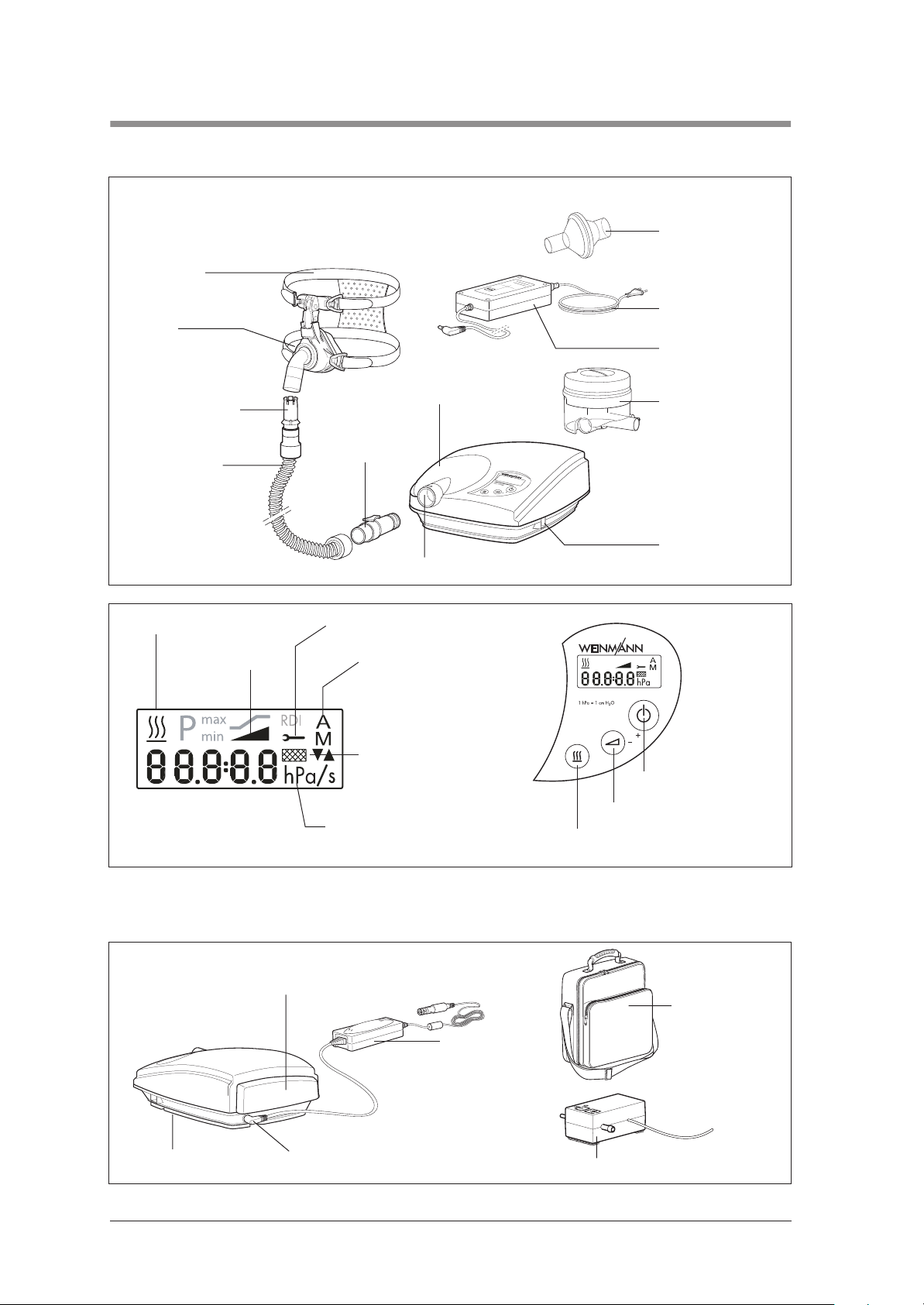
1. Overview
SOMNOcomfort 2/SOMNOcomfort 2e/SOMNObalance/SOMNObalance e
1 Bacteria filter
12 Head gear
11 Mask
10 Exhalation system
9 Breathing tube
13 Humidifier activated
15 Softstart time 16 Automatic switch on/off
8 Adapter
7 Unit outlet
14 Service symbol
5 Cover
H
H
M
i
T
O
P
o
R
D
w
E
e
O
r
L
S
:
N
u
X
p
e
p
X
l
In
e
l
c
y
c
Y
o
t
p
r
r
f
p
o
o
7
u
o
n
r
M
8
r
i
10
c
a
t
s
-
t
i
e
o
1
0
d
n
2
-
i
c
2
3
a
4
l
4
0
U
1.
O
5
V
s
OA
-
~
e
u
6
c
o
t
0
p
n
/
ly
5
u
0
2
t
H
4
V
z
-
-
2
.
1
CE
2 Power supply
cable
3 Power supply
4 Humidifier
6 Serial interface
17 Change filter symbol
18 Therapy pressure
22 Filter compartment cover,
air inlet
27 Rating plate 26 Supply connection
19 On/off switch
(stand-by)
20 Softstart button
21 Humidifier button
23 Carry case
24 DC adapter
25 O2 connection valve
4 Overview
Page 5

Legend
1 Bacteria filter (accessory)
Used to protect the patient from bacteria, particularly if the unit is being used by a
number of patients.
2 Power supply cable
Connects the power supply to the mains supply.
3 Power supply
Used to supply power to the unit.
4 Humidifier
Used to heat and humidify the air flow created by the therapy unit.
5 Cover
Connects the unit outlet with the humidifier connection. Is required if a humidifier is not
being used.
6 Serial interface
Connects the unit in order to display or evaluate therapy data or to connect the O2connection valve.
7 Unit outlet
The air flows from here via the breathing tube and mask to the patient.
8 Adapter
Connects the breathing tube to the unit outlet.
9 Breathing tube
The air flows through the breathing tube to the mask.
10 Exhalation system (accessory)
Exhalation air containing carbon dioxide is diverted here during the therapy.
11 Mask (accessory)
The mask is used to provide the patient with air at the required therapy pressure.
12 Head gear (accessory)
Helps locate the mask correctly and securely.
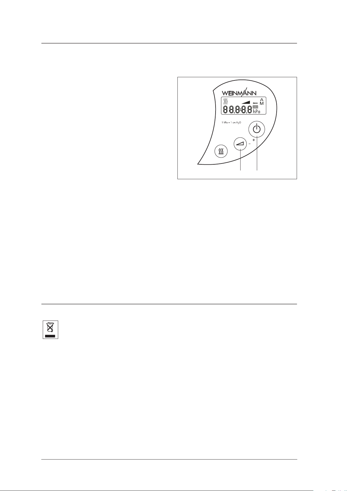
13 Humidifier activated
This symbol appears when the humidifier is in operation. The current humidity level is
displayed.
14 Service symbol
This symbol will appear after 5000 operating hours (SOMNOcomfort 2,
SOMNObalance) or 10.000 operating hours (SOMNOcomfort 2e,
SOMNObalance e). The unit must then be serviced.
15 Softstart time
This symbol appears when the softstart time is set or the softstart is activated.
16 Automatic switch on/off
The symbol "A" (automatic) appears when the Automatic switch on/off is active. The
symbol "M" (manual) appears when the Automatic switch on/off is inactive.
17 Change filter symbol
This symbol appears every 250 operating hours. The fine filter must then be changed.
18 Therapy pressure
The therapy pressure is shown in hPa. 1 hPa = 1 mbar = 1 cm H2O.
19 On/off switch (stand-by)
Switches the therapy unit on and off.
20 Softstart button
Activates the softstart or sets the softstart time (5 - 30 minutes in 5 minute steps).
21 Humidifier button
Activates the humidifier or sets the humidifier level (6 levels).
22 Filter compartment cover, air inlet
Covers and securely locates the coarse and fine dust filters.
Overview 5
Page 6
23 Carry case
For carrying the therapy unit.
24 DC adapter (accessory)
For operating the therapy unit via a DC socket (12 - 24 V).
25 O2 connection valve (accessory)
For introducing oxygen into the mask.
26 Supply connection
This is the connection for the external power supply or DC adapter.
27 Rating plate
Provides information about the unit, e.g. serial number and year built.
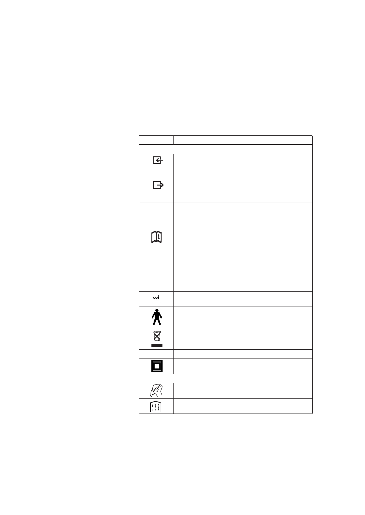
Special markings on the unit
Symbol Meaning
SOMNOcomfort 2/SOMNOcomfort 2e/SOMNObalance/SOMNObalance e:
Unit inlet: allows air at room temperature to enter
Unit outlet
SOMNOcomfort 2/SOMNObalance: air escapes with
4 - 18 hPa
SOMNOcomfort 2e/SOMNObalance e: air escapes with
4 - 20 hPa
Side connection socket:
SOMNOcomfort 2/SOMNOcomfort 2e
connection for setting the therapy parameters with SOMNOadjust
WM 23930 and SOMNOsupport WM 23975 by specialist staff
or to control the O2 connection valve, WM 24042. Max. current
consumption 163 mA.
SOMNObalance/SOMNObalance e
Serial port for setting therapy parameters using SOMNOadjust
WM 23930 or SOMNOsupport WM 23975 and for specialist
staff to read out raw data on the course of therapy for up to 180
therapy nights or for controlling O2 supply valve WM 24042.
Max. current consumption 163 mA. Analog output for therapy
pressure, flow, loss flow, relative respiratory minute volume and
OPP (obstructive pressure peaks) (0 to 1 V DC).
Year built
Unit type B
Do not dispose of the unit as domestic waste.
SN Unit serial number
Unit of protection class II
SOMNOaqua (optional)
Do not use the humidifier on patients whose airways have been
bypassed.
Unit is hot. Do not touch the heater rod.
6 Overview
Page 7

Markings on the packaging
Symbol Meaning
SOMNOcomfort 2/SOMNOcomfort 2e/SOMNObalance/SOMNObalance e:
SN Unit serial number
Unit of protection class II
Permitted temperature for storage: - 40˚C to + 70˚C
% 0-95 Permitted humidity for storage: max. 95% relative humidity.
Overview 7
Page 8

2. Description of the equipment
2.1 Intended use SOMNOcomfort 2 and SOMNOcomfort 2e
SOMNOcomfort 2 and SOMNOcomfort 2e are CPAP-Therapy units for the treatment of sleep related
respiratory disorders.
• SOMNOcomfort 2/SOMNOcomfort 2e
creates continuous positive airway pressure
(CPAP).
• While sleeping, the patient’s airways are
stabilized by the applied pressure.
• Air pressure is administered by means of a
breathing mask.
• SOMNOcomfort 2/SOMNOcomfort 2e can
be used for patients age 12 and up.
Important!
SOMNOcomfort 2/SOMNOcomfort 2e can
only reliably prevent airway closure when the
CPAP pressure prescribed by a doctor for the
specific patient has been calculated, e.g. in a
sleep laboratory. Pressure is set by either using the
SOMNOadjust remote control or
SOMNOsupport at the units front control panel.
SOMNOcomfort 2 and SOMNOcomfort 2e are
not designed for life support.
2.2 Intended use SOMNObalance and SOMNObalance e
SOMNObalance and SOMNObalance e are autoCPAP devices for treating sleep-related respiratory
disorders.
• SOMNObalance/SOMNObalance e
creates positive airway pressure (PAP),
• While sleeping, the patient’s airways are
stabilized by the applied pressure.
• The pressure is administered by a nasal or fullface mask.
• SOMNObalance/SOMNObalance e can
be used for patients age 12 and up.
• SOMNObalance/SOMNObalance e
detects respiratory events and varies airway
pressure accordingly.
• SOMNObalance/SOMNObalance e can
be operated with or without the
SOMNOaqua respiratory air humidifier.
• SOMNObalance/SOMNObalance e
displays therapy data on the device.
Important!
SOMNObalance/SOMNObalance e can only
reliably prevent airway blockage if the upper and
lower pressure limit prescribed by the doctor on a
patient-specific basis has been determined and set
accordingly, for example in a sleep laboratory.
SOMNObalance and SOMNObalance e are
not designed for life support.
8 Description of the equipment
Page 9

2.3 Functional description SOMNOcomfort 2 and SOMNOcomfort 2e
SOMNOcomfort 2 and SOMNOcomfort 2e operate according to the principle of an electrically driven flow
generator, with the pressure level being controlled electronically.
• A fan draws in ambient air via a filter and
conveys it to the unit outlet. From here the air
flows through the breathing tube and the mask
to the patient.
• A pressure sensor measures the pressure at the
unit outlet and shows this in the display. The
microprocessor-controlled flow generator
controls the pressure to the set value and
reduces fluctuations in pressure caused by
breathing.
• A softstart automatic system is installed to help
the patient fall asleep more easily. When the
unit is switched on, the CPAP pressure starts at
the initial pressure selected by the doctor and
is then slowly increased to the setpoint
pressure selected. The time of the pressure
increase can be adjusted between 5 and
30 minutes in 5 minute increments.
• The therapy unit offers an automatic on/off
feature. The unit can then be switched on by
breathing into the mask. If there is no pressure
for approx. 15 seconds (e.g. because the
mask has been removed), it will switch off
automatically.
• The therapy parameters are set by trained
personnel using the remote control system
SOMNOadjust or the evaluation program
SOMNOsupport.
• The therapy unit will automatically save all
settings in the event of a power failure. This
means that the unit does not need to be reset
when power is restored.
2.4 Functional description SOMNObalance and SOMNObalance e
• A fan draws in ambient air via a filter and
conveys it to the unit outlet. From here the air
flows through the breathing tube and the mask
to the patient.
• The exhalation system upstream of the mask
prevents the accumulation of CO2-enriched
exhaled air in the tube system. During sleep,
the patient's airways are braced by the air
pressure generated.
• The pressure in the mask is shown in the
therapy device display. The device determines
a respiratory flow signal which can be output
to a PSG system or also read out using
SOMNOsupport.
• The device analyzes the pressure and
respiratory flow signals and detects respiratory
events (e.g. apneas, hypopneas, flow
limitations and snoring).
• In APAP mode, therapy pressure is
automatically increased in the event of
obstructive respiratory events, but no higher
than the upper pressure limit prescribed by the
doctor. Once the events are over, therapy
pressure is slowly reduced again.
• The device can be operated in APAP and
CPAP modes, in each case with softPAP
exhalation relief as an option.
Description of the equipment 9
Page 10

3. Servicing
3.1 Intervals
Servicing every 2 years or 5000 operating hours
(SOMNOcomfort 2/SOMNObalance only)
Following components to be wiped down with disinfectant:
• Unit housing
• Filter compartment cover
• Cover
• Power supply
• Power supply cable
Replace filter – (see chapter 3.2, page 11)
Check proper device operation incl. pressure
measuring
Only if excessive soiling is present:
Clean inside using a vacuum cleaner:
• Unit housing
• Filter compartment cover
Clean areas of extreme soiling.
– (see chapter 4., page 13)
– (see chapter 5., page 15)
– Opening the unit (see chapter 7.4, page 23)
– Closing the unit (see chapter 7.5, page 24)
Servicing every 4 years or 10,000 operating hours / change of patient
Following components to be wiped down with
disinfectant:
• Unit housing
• Filter compartment cover
• Power supply
• Power supply cable
Clean inside using a vacuum cleaner:
• Unit housing
• Filter compartment cover
Clean areas of extreme soiling.
• Replace the following parts:
• Baffle box, assembled 53
• Cover 5
• Gasket, fan housing 66
• Foam, lower part 59
• Decoupling tube, outside 50
• Adapter, assembled 8
Replace filter – (see chapter 3.2, page 11)
Check proper device operation incl. pressure
measuring
– (see chapter 4., page 13)
– Opening the unit (see chapter 7.4, page 23)
– Closing the unit (see chapter 7.5, page 24)
– (see chapter 7.6, page 25)
– (see chapter 5., page 15)
10 Servicing
Page 11
3.2 Filter change
1. In order to prevent water from entering the
SOMNOcomfort 2/SOMNOcomfort 2e/
SOMNObalance/SOMNObalance e,
detach the humidifier 4 from the unit. When
doing so, please refer to the included
instructions for use.
2. Remove the filter compartment 22 cover on the
rear of the unit.
3. Remove the coarse dust filter 68.
4. Remove the fine dust filter 67.
5. Replace the filters and close the cover on the
rear of the unit.
6. Attach the humidifier where applicable. Please
refer to chapter “3.4 Humidifier” of the
instructions for use.
Clear the filter change indicator:
– When switching the unit on, press and hold
the on/off switch 19 until the filter change
indicator goes blank.
22
67 68
Reset the hours meter
If the fine filter was changed due to soiling before
250 operating hours, the hours meter must be reset
to zero. Proceed as follows:
1. When switching the unit on, press and hold
the on/off switch 19.
The filter change indicator will come on after
about three seconds before going off again
after another three seconds.
2. Release the on/off switch.
19
Servicing 11
Page 12
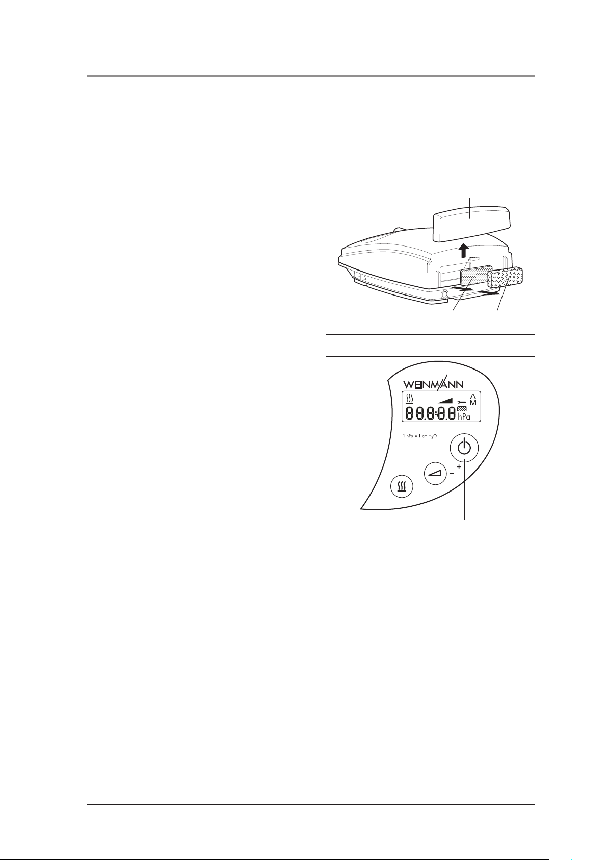
3.3 Reset service symbol
After every servicing and hygienic preparation the display’s service symbol 14 will have to be reset in order
to reset the service indicator back to 0 hours.
1. To delete the service symbol, ensure the unit is
switched off and press and hold softstart
button 20 until the setting option for Automatic
on/off (SOMNOcomfort 2/
SOMNOcomfort 2e) or the SoftPAP stage
(SOMNObalance/SOMNObalance e)
appears.
2. Now, additionally press the on/off switch 19,
until an S (for “key”) appears.
3. Now release both buttons.
1920
4. SOMNOcomfort 2/SOMNOcomfort 2e:
By pressing the on/off switch briefly 19 the
servicing indicator can be set and deleted.
SOMNObalance/SOMNObalance e:
Briefly pressing on/off switch 19 allows the
servicing code to be set. It is deleted by
pressing softstart button 20.
5. Additionally, a new servicing label should be
attached at the rear of the unit.
SOMNOcomfort 2/SOMNObalance:
Current year + 2
SOMNOcomfort 2e/SOMNObalance e:
Current year + 4.
3.4 Disposal
Do not dispose of the unit as domestic waste. To dispose of the unit properly, please contact a
licensed and certified electronic waste disposal merchant. Names and addresses can be obtained
from your Environmental Officer or municipal authorities.
12 Servicing
Page 13

4. Cleaning and disinfecting instructions
4.1 Cleaning and disinfecting while in use
Attention!
You will find appropriate instructions in Chapter 5. “Cleaning and disinfecting instructions” of the instructions
for use SOMNOcomfort 2/SOMNOcomfort 2e/SOMNObalance/SOMNObalance e.
The following describes the cleaning and disinfecting procedures while repairing or transferring the unit to
another patient.
4.2 Cleaning and disinfecting during repairs
During repairs, the following steps are to be performed by the authorized dealer!
Attention!
The instructions of disinfectant manufactures must
be adhered to (9.3, page 36). We recommend
that you wear suitable gloves when disinfecting the
equipment (e.g. household or disposable gloves).
• Disinfect outer housing and power supply
cable by wiping them down with TERRALIN.
• Clean or replace (depending on condition)
breathing tube, headgear and mask
according to the instructions for use.
• Open the unit according to 7.4.
• Replace 68 + 67 coarse- and fine dust filters.
• Vacuum clean inner housing and filter
compartment, clean areas of extreme soiling.
• Close the unit according to 7.5.
4.3 Cleaning and disinfecting, new patient
If the unit is to be disinfected and cleaned in order to transfer it to a new patient, the following steps should
be taken:
Attention!
The instructions of the disinfectant manufactures
must be adhered to (9.3, page 36). We
recommend that you wear suitable gloves when
disinfecting the equipment (e.g. household or
disposable gloves).
• Disinfect outer housing, power supply and
power supply cable by wiping them down
with TERRALIN. Dispose of the bag, breathing
tube and mask system, and replace with new
components.
• Open the unit according to chapter 7.4.
• Vacuum clean inner housing and filter
compartment, clean areas of extreme soiling.
• Replace 68 + 67 coarse- and fine dust filters.
• Cover 5, fan housing gasket 66, foam 59,
decoupling tube 50, adapter 8 must be
replaced.
• Baffle box 53 should be replaced according to
chapter 7.10.
• Close the unit according to chapter 7.5.
Cleaning and disinfecting instructions 13
Page 14

4.4 Cleaning and disinfecting the humidifier while in use
You will find corresponding instructions in chapter 4. “Disinfecting and cleaning instructions” of the
instructions for use SOMNOcomfort 2(e).
4.5 Cleaning and disinfecting the humidifier, new patient
If the unit is to be disinfected and cleaned in order to transfer it to a new patient, the following steps should
be taken:
• For hygiene reasons, we recommend that the
plastic parts are replaced after a maximum of
two years use. The replacement part list can
be found in the instructions for use
SOMNOcomfort 2/SOMNOaqua or
SOMNObalance/SOMNOaqua.
• If plastic components and heater rod are
extremely soiled or encrusted with lime you
should use a new unit, otherwise
proceed according to chapter 4.
“Disinfecting and cleaning instructions” of the
instructions for use SOMNOcomfort 2(e).
14 Cleaning and disinfecting instructions
Page 15

5. Final test
5.1 General
Important!
A final test is required after each and every repair.
Please maintain a record of all maintenance and
service work that you perform. We suggest that you
maintain this record on a service record form, as
found on page 34 of this manual. You may photocopy
this page for manual entry, or obtain the manual in
PDF format, display it using Acrobat Reader, complete
it on a PC, and print it.
Enter the following values for SOMNOcomfort 2/
SOMNOcomfort 2e in your service record (see
page 42):
• Operating hours
• Humidity level
• Softstart time and initial pressure
• Patient’s therapy pressure
Enter the following values for SOMNObalance/
SOMNObalance e in your service record (see
page 42):
• Operating hours
• Humidity level
• Softstart time and initial pressure
• Mode
for CPAP: therapy pressure
for APAP: bottom and top pressure limit, rise
speed as per patient record
If you detect errors or deviations from defined
values in the course of your final testing you must
not redeploy SOMNOcomfort 2/
SOMNOcomfort 2e/SOMNObalance/
SOMNObalance e before these errors have been
eliminated. You can determine possible causes of
such errors and recommended countermeasures by
referring to chapter “6. Troubleshooting” on
page 19.
5.2 Performing the test
5.2.1 Preparation
– Assemble the therapy unit ready to use
including breathing tube 9, mask 11, power
supply 3 and power supply cable 2.
5.2.2 Checking the power supply cable
1. Check the power supply cable 2.
Make sure that
– insulation is intact,
– the cable is not damaged,
– and that there are no loose connections.
2. Replace the power supply cable 2 if
necessary.
Final test 15
Page 16

5.2.3 Checking the power supply
1. Connect the power supply 3 to an available
power source.
– If the LED lights up, the power supply is in
order.
2. Replace the power supply 3 if necessary.
5.2.4 Checking the housing
– Check the housing’s general condition.
If the housing is damaged in any way, replace
the respective part of the housing (see also
Chapter 7.12, Page 31 and Chapter 7.13,
Page 31).
5.2.5 Checking the control panel and indicators
1. Make sure that front panel foil of the control
panel is attached flush and tight. If this is not
the case, replace the foil (see chapter “7.7”
on page 26).
2. You should now establish the power supply
by connecting the power supply 3 and the
power supply cable 2 to the unit and an
available power outlet.
3. Close the opening of the mask, e.g. using your
thumb or hand and hold it closed.
4. Push the on/off switch 19 to switch the device
on.
On the display, the total hours of operation
will be indicated for 3 seconds before the
current measured pressure will appear.
5. Press the Softstart button 20. The display will
change.
6. Switch the unit off using the 19 switch.
The display will show the date and the day’s
length of therapy for a short while.
Subsequently only “0” and “A” or “M” will be
shown.
1921 20
16 Final test
Page 17

5.2.6 Checking proper functionality of the therapy unit
1. Switch on the therapy unit.
2. Close the opening of the mask, e.g. using your
thumb or hand and hold it closed.
3. If the mask test is activated on
SOMNObalance/SOMNObalance e,
switch it off using button 20. If softstart is
switched on, then deactivate this as well,
likewise using button 20.
The radial fan will transport air to the mask
through the breathing tube, and the display
will show the current pressure in hPa.
4. Compare the pressure shown on the display
with the CPAP pressure prescribed. After
approx. 1 minute the maximum allowable
pressure deviation is ± 0.2 hPa.
5. Replace the masks with pressure measurement
adapter WM 23456 and connect it to an
exhalation system, e.g. WM 23685. Seal the
top opening with the red plug for drying
(WM 23639).
6. Connect the lateral connector to a pressure
measurement device.
7. Switch on the therapy device. If softstart is
active, switch it off using button 20.
8. Compare the value displayed by the pressure
measurement device with the value in the LC
display. After approx. 1 minute the maximum
allowable pressure deviation is ± 1 hPa.
9. Press the 20 button to activate softstart. The
softstart indicator 15 will appear and the
display will show the softstart time.
Concurrently, the CPAP pressure will be
reduced to the set softstart initial pressure.
The initial softstart pressure can be adjusted.
(see chapter “2.3” on page 9).
10. The pressure increases slowly and reaches the
CPAP pressure after the time selected. The
softstart indicator 15 will disappear.
With SOMNObalance/SOMNObalance e,
it is the set bottom pressure limit, not the
prescribed CPAP pressure, which is reached
in APAP mode.
11. Switch the therapy unit off.
12. Press and hold softstart button 20 until the
setting option for Automatic on/off
(SOMNOcomfort 2/SOMNOcomfort 2e) or
the SoftPAP stage (SOMNObalance/
SOMNObalance e) appears. On
SOMNObalance/SOMNObalance e, press
the humidifier button to reach the setting option
for Automatic on/off.
1921 20
Final test 17
Page 18

13. In order to switch to the “A” setting, push the
on/off button 19.
– The therapy unit will now switch on
automatically when breathing into the mask
(pressure > 0,5 hPa),
– If the mask is removed, the unit should
switch off after approx. 15 seconds.
14. Switch the unit off using the button 19. The
display will show the date and the day’s
length of therapy for a short while.
Subsequently only “0” and “A” will be shown.
5.2.7 Checking proper function of the humidifier
1. Check the plastic housing visually:
if tears/damage or heavy soiling are found,
the plastic parts or gaskets must be replaced.
2. Fill the humidifier up to the mark with water.
3. Check whether the humidifier is leaking.
4. Empty the water.
5. Now pour in about 50 ml of water.
6. Attach the humidifier.
7. Attach the breathing tube to the unit.
8. Switch the therapy unit on.
9. Switch the humidifier on by pressing the
humidifier button on the therapy unit.
10. Set heater level 6 on the therapy unit.
11. Check whether the humidifier is getting
warmer.
12. Remove the breathing tube by pressing the
adapter’s locking button.
1921 20
18 Final test
Page 19

6. Troubleshooting
Malfunction Cause Rectification
Check connections between the power supply
cable and the unit, wall outlet respectively.
No power.
Fuse defective. Replace fuse (Chapter 7.8, Page 27).
No mechanical sound, ready
and operating indicator is off.
No mechanical sound after
operating indicator turns on.
Defective or no display. Display defective. Replace display (Chapter 7.9, Page 27).
Pressure tolerance of the CPAP is
> 1 hPa after 1 minute.
Unit will not switch on by
breathing into the mask while in
automatic mode.
Unit is running but does not
reach CPAP pressure level
selected.
Unit does not switch off after
approx.15 seconds once mask
is removed.
Filter change indicator on
the display.
Flat cable connection of the
display has slipped from the
socket.
Supply connection line 64 loose
or defective.
Main circuit board defective.
If the powerpack’s LED is off:
Power supply defective.
Motor is not turning.
Fan connection line loose or
defective.
Main circuit board defective.
Automatic mode switched off.
Main circuit board defective.
Using a full-face mask with
integrated exhalation system.
Filter soiled. Replace both filters (Chapter 3.2, Page 11).
Mask leaking. Adjust headgear so that mask is airtight.
Cover or humidifier not attached/
inserted.
Pressure measurement tube kinked
or loose.
Automatic switch on/off not
activated.
Using a high-resistance mask (e.g.
"nasal pillow" masks).
Filter soiled, end of filter life cycle
reached.
Check the power source with another device
(e.g. lamp) if necessary.
If necessary, replace power supply cable.
Check connection to main circuit board
(Chapter 7.6, Page 25).
Reattach (Chapter 7.5, Page 24) or replace line
(Chapter 7.12, Page 31).
Replace main circuit board (Chapter 7.6,
Page 25).
Replace powerpack.
Replace main circuit board (Chapter 7.6,
Page 25).
Replace fan (Chapter 7.11, Page 30).
Reattach (Chapter 7.6, Page 25) line or replace
fan (Chapter 7.11, Page 30).
Replace main circuit board (Chapter 7.6,
Page 25).
Activate automatic mode (see 4.1 of the
instructions for use).
Replace main circuit board (Chapter 7.6,
Page 25).
Automatic on is not an option with this type of
mask (see instructions for use for
SOMNObalance/SOMNObalance e, Section
4.4 "Automatic on/off").
Insert/attach humidifier or cover.
Attach the pressure measurement tube and close
the unit in a manner avoiding kinks.
Activate automatic mode (see 4.1 of the
instructions for use).
Automatic off is not an option with this type of
mask.
Clean/change both filters (Chapter 3.2,
Page 11).
Troubleshooting 19
Page 20

Malfunction Cause Rectification
Check using another humidifier, if necessary
Humidifier defective.
Humidifier water will not warm
up.
Power supply cable defective. Replace power supply cable.
Err b
Err E
Err S
Err c
Err A
Err P
Err h
Main circuit board defective.
Humidifier connection line 49
loose or defective.
Back-up battery weak/depleted.
EEPROM data erased/damaged.
Hardware defective (fuse, motor
driver).
EEPROM cell containing
calibration data erased/
defective.
Pressure sensor defective.
Hardware defective (pressure
sensor, motor driver).
Hardware defective (humidifier
output stage).
replace heating rod (see instructions for use
SOMNOcomfort 2/SOMNOcomfort 2e/
SOMNObalance/SOMNObalance e).
Replace main circuit board (Chapter 7.6,
Page 25).
Reattach (Chapter 7.6, Page 25) or replace line.
Replace main circuit board (Chapter 7.6,
Page 25).
On SOMNObalance/SOMNObalance e
Err10
Err20
Err30
Err31
Err40
Err50
Err60
Err70
Err80
Calibration fault
EEPROM fault
Pressure sensor fault
Pressure fault
Data fault [flash]
Battery fault
Speed fault (fan)
Humidifier fault
RTC fault
Replace main circuit board (Chapter 7.6,
Page 25).
Replace main circuit board (Chapter 7.6,
Page 25) and/or replace fan (Chapter 7.11,
Page 30).
Replace main circuit board (Chapter 7.6,
Page 25).
20 Troubleshooting
Page 21

7. Repair information and repair instructions
7.1 General
Please perform repairs on SOMNOcomfort 2/SOMNOcomfort 2e/SOMNObalance/SOMNObalance e
at an ESD workstation!
• Refer to the safety instructions in the instructions
for use for SOMNOcomfort 2/
SOMNOcomfort 2e/SOMNObalance/
SOMNObalance e.
• Any handling of this device requires in-depth
knowledge of and adherence to the
instructions for use and the servicing and
repair instructions.
• Perform repairs described in this servicing and
repair instructions only. This is the only way to
ensure that SOMNOcomfort 2/
SOMNOcomfort 2e/SOMNObalance/
SOMNObalance e work properly.
• Make sure that your hands and your
workspace are clean when performing
repairs.
• After every repair a servicing check must be
performed (see “5. Final test” on page 15).
• When replacing components or single parts,
use genuine Weinmann replacement parts
only.
• When ordering the unit’s lower part of the
housing 48 you have to state unit type, built
and serial number.
Note:
The item numbers stated in the following text are
identical with the item numbers of the Replacement
parts list on page 33 and the overview on page 4.
7.2 Tools and facilities
In order to perform the repairs described in this chapter, you will need the following tools and facilities:
• Torx Screwdriver T 20
• Phillips screwdriver PZ 2
• Ball-headed Allen wrench 3 mm
• Knife with a flat smooth blade for removing the front panel foil
• Scissors or scalpel for removing motor mounts
• Nail scissors or ticket-punch to mark the servicing plaque
• ESD Workstation
Repair information and repair instructions 21
Page 22

7.3 Sequence of repairs
The following schematic is intended to help you determine the order of required repair steps.
Opening the
unit
Replace fuse
Replace
housing
lower part
Remove main
circuit board
Insert main
circuit board
Replace front
panel foil
Remove the
display
+
Replace
housing, upper
part
+
Attach display
Remove baffle
box
Remove
fan
Attach baffle
box
22 Repair information and repair instructions
Close
the unit
Perform final
test
Page 23

7.4 Opening the unit
Attention!
Do not open the unit unless the power is disconnected.
1. Remove the covering cap.
2. Place the unit upside down on a non-slip
surface.
3. Remove the six screws 70.
70
4. Remove the lower part of the housing 48 with
a swivelling motion away to the side.
5. Remove the connector X1 from the circuit board
and pull the connecting cable 64 from its
mount.
6. Now you can set aside the lower part of the
housing 48.
SOMNOcomfort 2/SOMNOcomfort 2e
48
64
X1
SOMNObalance/SOMNObalance e
48
64
X1
Repair information and repair instructions 23
Page 24

7.5 Closing the unit
1. Hold the lower part of the housing 48 to the
upper part at an angle 47.
2. Attach connector X1 to the main circuit board
44. When doing so the connector’s nub has to
point towards the lock.
3. Properly align the main circuit board 44 inside
the unit.
SOMNOcomfort 2/SOMNOcomfort 2e
48
64
X1
4. Attach the connecting cable 64 to its mount.
5. Place the lower part of the housing 48 on the
upper part at 47.
Please make sure the main circuit board is
aligned properly 44 and that the connecting line
64 is not being squeezed in anywhere.
6. Now reattach the upper part of the housing by
tightening the six screws 70.
7. Insert the covering cap.
44
47
SOMNObalance/SOMNObalance e
48
64
X1
44
47
70
24 Repair information and repair instructions
Page 25

7.6 Replacing the main circuit board
1. Open the unit (chapter 7.4, page 23).
Remove the main circuit board
1. Pull the plug X200 and X400 from the main
circuit board.
2. Remove the flat cables from front panel foil
and display:
To do so, pull the lock. Once you have pulled
the lock, you can remove the flat cable.
3. Remove pressure measurement tube 45 from
the pressure sensor or pull out the tube adapter
of the pressure measurement tube.
4. der Winkeltülle auf dem Drucksensor.
5. Remove the main circuit board 44.
SOMNOcomfort 2/SOMNOcomfort 2e
X200
X400
45
Flat cable Lock
44
SOMNObalance/SOMNObalance e
X200
X400
45
Inserting the main circuit board
1. Attach tube 45 to the pressure sensor of a new
main circuit board 44 or connect the tube
adapter of the pressure measurement tube to
the angular bush on the pressure sensor.
2. Insert the main circuit board.
Flat cable Lock
44
SOMNOcomfort 2/SOMNOcomfort 2e
X200
X400
45
Flat cable Lock
44
Repair information and repair instructions 25
Page 26

3. Reattach the flat wires of front panel foil and
display to the main circuit board:
– Pull the lock.
– Insert the flat cable into the connector.
– Push the lock back in.
4. Connect plugs X200 and X400 to the main
circuit board.
5. Close the unit (chapter 7.5, page 24).
6. Check that everything is working properly
(chapter 5., page 15).
SOMNObalance/SOMNObalance e
X200
X400
45
7.7 Replacing the front panel foil
1. Open the unit (chapter 7.4, page 23).
2. Remove the main circuit board (chapter 7.6,
page 25, steps 1. to 5.).
3. Loosen the front panel foil 52 using a knife and
remove it.
4. Degrease this section of the housing using a
70 % Isopropanol solution.
5. Attach a new foil 52 to the housing.
Make sure the flat cable is inserted into the
corresponding opening of the housing cleanly
without any kinks.
6. Remove the protective foil from the new front
panel foil.
7. Insert the main circuit board (chapter 7.6,
page 25, steps 1. to 4.).
8. Close the unit (chapter 7.5, page 24).
9. Check that everything is working properly
(chapter 5., page 15).
Flat cable Lock
52
44
26 Repair information and repair instructions
Page 27

7.8 Replacing the fuse
1. Open the unit (chapter 7.4, page 23).
2. Remove the defective fuse and replace with a
new one.
Ensure the correct amperage is used.
Use fuses mentioned in the Replacement parts list
only. Using other fuses may cause damage to the
main circuit board.
3. Close the unit (chapter 7.5, page 24).
4. Check that everything is working properly
(chapter 5., page 15).
SOMNOcomfort 2/SOMNOcomfort 2e
77
SOMNObalance/SOMNObalance e
76
7.9 Replacing the display
1. Open the unit (chapter 7.4, page 23).
2. Remove the main circuit board (chapter 7.6,
page 25, steps 1. to 5.).
Remove the display
1. Loosen the two screws 71.
2. Remove the decoupling tube 50 from the box.
71
50
Repair information and repair instructions 27
Page 28

3. Remove the decoupling tube including the
insert.
50
4. Loosen the screw 72.
5. Remove the display 51.
Attaching the display
1. Glue new foam 61 to the display 51.
2. Insert the new display.
3. Tighten the screw 72 using the spring 79.
4. Attach the decoupling tube.
– Connect the decoupling tube to the box.
– Insert the decoupling tube including the
insert.
– Tighten the screw 71 firmly, but not too tight.
Note: If the screws are too tight it may
become difficult to install the cover 5.
5. Insert the main circuit board (chapter 7.6,
page 25, steps 1. to 4.).
6. Close the unit (chapter 7.5, page 24).
7. Check that everything is working properly
(chapter 5., page 15).
72
79
51
7.10 Replacing the baffle box
1. Open the unit (chapter 7.4, page 23).
2. Remove the main circuit board (“7.6
Replacing the main circuit board” on
page 25, steps 1. to 5.).
Remove the baffle box
1. Remove the decoupling tube 53 from the box.
2. Remove the box 53 in an upwards motion.
28 Repair information and repair instructions
53
50
Page 29

Attaching the baffle box
1. Place foam 58 on the box, soft side up. You
must be able to see the screw heads of the box
through the holes in the foam.
2. Insert box and foam into the housing. Make
sure the foam is spread out evenly.
3. Pull the protective backing off the adhesive
tape and stick on foam 59. Use the crosses as
a positioning aid.
58
53
59
53+58
4. Apply a small amount of 70 % Isopropanol
solution on the decoupling tube’s 50
circumference and attach it to the box.
The tube’s notch must completely lock into the
bore hole rim.
5. Insert the main circuit board (chapter 7.6,
page 25, steps 1. to 4.).
6. Close the unit (chapter 7.5, page 24).
7. Check that everything is working properly
(chapter 5., page 15).
47
53
50
Repair information and repair instructions 29
Page 30

7.11 Replacing the fan
Remove the fan
1. Open the unit (see “7.4 Opening the unit” on
page 23).
2. Remove the box 53 (see “7.10 Replacing the
baffle box” on page 28 steps 1. to 2.).
3. Remove the four 69 screws.
4. Remove the box cover and the attached 60
foam part.
5. Pull the two parts of the box apart.
6. Pull the decoupling tube 55 out of the motor
frame’s bore hole.
7. Loosen the motor mount 54. Cut the mount
using scissors or scalpel.
8. Remove the fan 65.
55
61
54
Cut-out
60
Inserting the fan
1. Place three new motor mounts 54 into the box.
2. Insert the fan 65 into the motor frame and
attach it using the motor mounts 54. Pull the
motor mounts through the bore holes of the fan
to reach the surrounding notch.
3. Apply a small amount of 70 % Isopropanol
solution on the decoupling tube’s 55
circumference and attach it to the box.
The tube’s notch must completely lock into the
bore hole rim.
4. Reconnect the two parts of the box. Pay
attention to proper alignment of the foam part 61
and the correct cable lead. The cable must be
placed in the appropriate cut-out.
5. Place the cover on the box and insert the
screws.
6. Insert the box (chapter 7.10, page 28 steps 1.
to 4.).
7. Insert the main circuit board (chapter 7.6,
page 25, steps 1. to 4.).
8. Close the unit (chapter 7.5, page 24).
69
Cover
9. Check that everything is working properly
(chapter 5., page 15).
30 Repair information and repair instructions
Page 31

7.12 Replacing the housing, lower part
1. Open the unit (chapter 7.4, page 23).
2. Loosen the lock and pull the connection plug
64 from the lower part of the housing 48 in an
upward motion.
3. Place the connecting line 64 with the plug
pointing downwards into the socket of the new
housing 48. The plug will lock in.
4. Close the unit (chapter 7.5, page 24).
5. Check that everything is working properly
(chapter 5., page 15).
7.13 Replacing the housing, upper part
1. Open the unit (chapter 7.4, page 23).
2. Remove the main circuit board (chapter 7.6,
page 25, steps 1. to 5.).
3. Remove the display (chapter 7.9, page 27,
steps 1. to 5.).
4. Disassemble the adapter pressure gland 78.
5. Remove the box 53 (chapter 7.10, page 28,
steps 1. to 2.).
You have now removed all of the parts. Now
begin to reassemble them back into the new upper
part of the housing 47.
6448
78
6. Attach front panel foil 52 to the housing.
Make sure the flat cable will be inserted into the
according opening of the housing cleanly without
any kinks.
7. Remove the protective foil from the new front
panel foil.
8. Insert the box 53 (chapter 7.10, page 28,
steps 1. to 4.).
9. Attach the adapter pressure gland 78.
The nub of the silicone part must be inserted into
the appropriate cut-out of the plastic part (see
illustration).
10. Insert the display (chapter 7.9, page 27,
steps 2. to 4.).
11. Insert the main circuit board (chapter 7.6,
page 25, steps 1. to 4.).
12. Close the unit (chapter 7.5, page 24).
Repair information and repair instructions 31
Page 32

13. Insert a new fine dust filter 67 followed by a
coarse dust filter 68.
14. Reattach the filter compartment cover 22.
15. Check that everything is working properly
(chapter 5., page 15).
22
6867
32 Repair information and repair instructions
Page 33

8. Replacement parts
8.1 Replacement parts list
Note:
The item numbers of the following table are identical to the numbers used in the body text of this servicing
and repair instructions.
Item-No. Name Ordering-No.
2 Power supply cable WM 24133
3 Power supply WM 24480
5
8
9 Breathing tube WM 24445
22
23 Bag WM 24449
24 DC adapter WM 24469
28 Set of 2 coarse dust filters WM 15321
29 Set of 12 fine filters WM 15668
Cover, white
Cover, dark-grey
Adapter, installed white
Adapter, installed dark-grey
Filter compartment cover, white
Filter compartment cover, dark-grey
WM 24424
WM 24489
WM 24452
WM 24493
WM 24428
WM 24470
30 Servicing set, white WM 15687
31 Servicing set, dark-grey WM 15688
32 Instructions for use SOMNOcomfort 2/SOMNOaqua DE WM 16892
33 Instructions for use SOMNObalance/SOMNOaqua DE WM 66200
34 Instructions for use SOMNOcomfort 2/SOMNOaqua FR, IT WM 16893
35 Instructions for use SOMNObalance/SOMNOaqua FR, IT WM 66202
36 Instructions for use SOMNOcomfort 2e/SOMNOaqua DE WM 16894
37 Instructions for use SOMNObalance e/SOMNOaqua DE WM 66205
38
39
40 Instructions for use SOMNOcomfort 2e/SOMNOaqua GB WM 16896
41 Instructions for use SOMNObalance e/SOMNOaqua GB WM 66206
42 Setup instructions for SOMNOcomfort 2/2e DE, GB, FR WM 16980
43 Setup instructions for SOMNObalance/e DE, GB, FR WM 66215
Instructions for use SOMNOcomfort 2e/SOMNOaqua FR, NL,
IT
Instructions for use SOMNObalance e/SOMNOaqua FR, NL,
IT
WM 16895
WM 66207
Replacement parts 33
Page 34

Item-No. Name Ordering-No.
Main circuit board SOMNOcomfort 2
Main circuit board SOMNOcomfort 2e
Main circuit board SOMNObalance
44
Main circuit board SOMNObalance AT
Main circuit board SOMNObalance e
Main circuit board SOMNObalance e AT
Foam, circuit board
45 Pressure measurement tube (0.14 m) WM 23955
46 Fine dust filter, packaged WM 24401
47
48 Housing, lower part, with nameplate * WM 24595
49 Humidifier connection line WM 24419
50 Decoupling tube, outside WM 24429
51 Display WM 24437
Housing, upper part, white
Housing, upper part, dark-grey
Front foil SOMNOcomfort 2
52
Front foil SOMNOcomfort 2e
Front foil SOMNObalance
Front foil SOMNObalance e
53 Baffle box, installed WM 24439
54 Motor mount WM 24444
55 Decoupling tube, inside WM 24446
56 Pressure gland WM 24447
57 Cleaning plug, packaged WM 24451
58 Foam, housing, upper part WM 24453
59 Foam, lower part WM 24454
60 Foam, cover WM 24457
61 Foam, small WM 24466
62 Baffling foil (course foil), below unit WM 24471
63 Unit mount (foam mount) WM 24472
64 Connecting cable, power supply WM 24473
65 Fan WM 24474
66 Gasket, fan housing WM 24475
67 Fine filter WM 24478
68 Coarse dust filter WM 24481
69 Screw Ejot PT K 40x70 WN 1412 WM 50557
70 Screw Ejot PT K 40x14 WN 1412 WM 50558
71 Screw DIN 912 M4x30 WM 50559
WM 24430
WM 23530
WM 27490
WM 27488
WM 27480
WM 27489
WM 27418
WM 24416
WM 24482
WM 24438
WM 24484
WM 27408
WM 27428
72 Screw Ejot PT K 40x8 WN 1412 WM 50561
73 Square nut DIN 562 M4 Ms-Ni WM 50568
74 Gasket, unit outlet WM 1145/156
* When placing an order please make sure to include type, unit serial no. and year built.
34 Replacement parts
Page 35

Item-No. Name Ordering-No.
75
76 Set of 10 breathing tubes WM 15689
77 Fuse WM 13422
78 Adapter, pressure gland WM 24448
79 Spring for display WM 24402
Breathing tube with adapter, white
Breathing tube with adapter, dark-grey
WM 24396
WM 24397
8.2 Replacement parts required for servicing
Servicing set 10,000 operating hours or 4 years
Set WM 15687
(for SOMNOcomfort 2/SOMNOcomfort 2e/SOMNObalance/SOMNObalance e, white)
Consisting of:
• 1 Coarse dust filter
• 1 Fine filter
• 1 Baffle box, installed
• 1 Gasket, fan housing
• 1 Foam, lower part
• 1 Decoupling tube, outside
• 1 Cover cap
• 1 Adapter, installed
• 1 Label, recycling
Set WM 15688
(for SOMNOcomfort 2/SOMNObalance, dark-grey)
Consisting of:
• 1 Coarse dust filter
• 1 Fine filter
• 1 affle box, installed
• 1 Gasket, fan housing
• 1 Foam, lower part
• 1 Decoupling tube, outside
• 1 Cover cap
• 1 Adapter, installed
• 1 Label, recycling
Replacement parts 35
Page 36

9. Tools, testing equipment and disinfectants
The following is a list of all tools and testing equipment mentioned in this servicing and repair instructions.
9.1 Tools
• Torx Screwdriver T 20
• Phillips screwdriver PZ 2
• Ball-headed Allen wrench 3 mm
• Knife with a flat smooth blade for removing the
front panel foil
9.2 Testing equipment
• Mobile pressure measuring device,
accuracy ± 0.1 %
e.g. type GMH 3110
with pressure sensor 0-25 hPa
Type GMSD 25 MR
Can be ordered from:
Greisinger electronic GmbH
Hans-Sachs-Str. 26
D-93128 Regenstauf / Germany
Tel.: +49 9402-8500, Fax: -1829;
• SOMNOsupport
• ESD Workstation
• Scissors or scalpel for removing motor mounts
• Nail scissors or ticket-punch to mark the
servicing plaque
• ESD Workstation
• Remote control SOMNOadjust ,
for adjusting the pressure
To be ordered from: WM 23930
of the manufacturer Weinmann.
• Remote cable 2 m
required to adjust pressure
To be ordered from: WM 23772
of the manufacturer Weinmann.
• Pressure measurement adapter WM 23456
• Noise insulation WM 23685
• Plug for drying WM 23639
9.3 Disinfectant
• TERRALIN
Can be ordered from:
Schülke & Mayr GmbH
Robert-Koch-Str. 2
D-22851 Norderstedt / Germany
Tel.: +49 40 52 100 - 0
Fax: +49 40 52 100 - 318
Internet: www.schuelkemayr.de
36 Tools, testing equipment and disinfectants
Page 37

10. Technical data
10.1 Specifications for SOMNOcomfort
SOMNOcomfort 2 SOMNOcomfort 2e
Product category according to 93/42/EEC IIa
Dimensions WxHxD in cm 21 x 9 x 27 21 x 14 x 27
Weight approx. 1.7 kg approx. 1.9 kg (without water)
Temperature range
– operation
– storage
If the unit runs at +40 °C , the air output can heat up to 42 °C .
Adm. humidity for operation and storage ≤ 95 % rF (no condensation)
Air pressure range 600 - 1100 hPa (allows operation at altitudes of up to 4000 m)
Diameter of breathing tube connection (mask)
in mm
Electrical connection
Power consumption during
– operation
– standby
Classification as per
prEN 60601-1:2004
– type of protection from electric shock
– level of protection from electric shock
– protection against damaging ingress of
water
– operating mode
Electromagnetic compatibility (EMC) as per
EN 60601-1-2
– radio interference suppression
– radio sheilding
Mean sound pressure level/operation at
distance of 1m from unit in patient position
CPAP operating pressure range
power supply or 12-24 V DC +25/-15 % with WM 24469 DC adapter
230 V 115 V 24 V 12 V
0.1 A 0.2 A 0.9 A 1.8 A
0.02 A 0.03 A 0.02 A 0.24 A
Test parameters and limit values can be obtained from the manufacturer if required.
4 to 18 hPa
19.5 (suitable for 22 mm standard cone)
100-240 V AC +10/-15 %, 50–60 Hz with WM 24480
(corresponds to an acoustic power level of 35 dB (A) )
+5 °C to +35 °C
–40 °C to +70 °C
Protection class II
Constant operation
EN 61000-4 parts 2 to 6, part 11
approx. 27 dB (A) at 10 hPa
4 to 20 hPa
SOMNOcomfort 2
with SOMNOaqua
230 V 115 V 24 V 12 V
0.23 A 0.45 A 2.0 A 4.0 A
0.02 A 0.03 A 0.2 A 0.24 A
Type B
IPX1
EN 55011 B
4 to 18 hPa
SOMNOcomfort 2e
with SOMNOaqua
4 to 20 hPa
pressure accuracy
Flow at max. speed at:
18 hPa
14 hPa
12 hPa
9 hPa
6 hPa
5 hPa
4 hPa
0 hPa
Tolerance
Flow at max. speed at:
20 hPa
15 hPa
10 hPa
5 hPa
0 hPa
Tolerance
Heating of respiratory air 2.5 °C depending on heating level
±1 hPa
(1mbar = 1 hPa
≈ 1cm H2O)
120 l/min
130 l/min
140 l/min
150 l/min
155 l/min
160 l/min
175 l/min
175 l/min
±15 l/min
±1 hPa
(1mbar = 1 hPa
≈ 1cm H2O)
115 l/min
125 l/min
145 l/min
160 l/min
175 l/min
±15 l/min
±1 hPa
(1mbar = 1 hPa
≈ 1cm H2O)
120 l/min
130 l/min
140 l/min
150 l/min
155 l/min
160 l/min
175 l/min
175 l/min
±15 l/min
±1 hPa
(1mbar = 1 hPa
≈ 1cm H2O)
115 l/min
125 l/min
145 l/min
160 l/min
175 l/min
±15 l/min
Technical data 37
Page 38

SOMNOcomfort 2 SOMNOcomfort 2e
Short-term constant pressure level measured as
per prEN ISO 17510:2004 at:
18 hPa
14 hPa
9 hPa
5 hPa
4 hPa
Long-term constant pressure level
prEN 17510-1:2004
Short-term constant pressure level measured as
per prEN ISO 17510:2004 at:
20 hPa
15 hPa
10 hPa
5 hPa
Long-term constant pressure level
prEN 17510-1:2004:
Finefilter separation level
to 1 µm
to 0.3 µm
Fine filter service life ≤ 250 hours with normal room air
Δp = 0,5 hPa
Δp = 0,5 hPa
Δp = 0,4 hPa
Δp = 0,4 hPa
Δp = 0,4 hPa
Δp = 0,1 hPa
Δp = 0,5 hPa
Δp = 0,5 hPa
Δp = 0,4 hPa
Δp = 0,4 hPa
Δp = 0,1 hPa
SOMNOcomfort 2
with SOMNOaqua
Δp = 0,5 hPa
Δp = 0,5 hPa
Δp = 0,4 hPa
Δp = 0,4 hPa
Δp = 0,4 hPa
Δp = 0,1 hPa
≥ 99.5 %
≥ 85 %
Subject to design modifications.
SOMNOaqua
Product class as per 93/42/EEC
Dimensions WxHxD in mm 140 x 100 x 121
Weight (without water) 300 g
Temperature range
– operation
– storage
Humid operation and storage ≤95 % relative humidity
Ambient pressure range 600 to 1100 hPa
Electrical connection 24 V DC
Power consumption 15 VA
Classification as per EN 60601-1
– level of protection from electric shock type B
Max. permitted capacity 300 ml
Max. permitted operating pressure 20 hPa
Max. permitted flow (free-flowing) 200 l/min
Max. mask temperature 37 °C
Gas leakage
– at 20 hPa (SOMNOcomfort 2e)
– at 18 hPa (SOMNOcomfort 2)
Humidifier output at heating level 6:
Flowrate = 20 l/min
Flowrate = 30 l/min
Flowrate = 40 l/min
at 23 ° C and 65 % relative humidity
II a
+5 °C to +35 °C
–40 °C to +70 °C
negligible
6.3 mg/l
6.8 mg/l
9.0 mg/l
SOMNOcomfort 2e
with SOMNOaqua
Δp = 0,5 hPa
Δp = 0,5 hPa
Δp = 0,4 hPa
Δp = 0,4 hPa
Δp = 0,1 hPa
Subject to design modifications.
38 Technical data
Page 39

10.2 Specifications for SOMNObalance
SOMNObalance SOMNObalance e
Product category according to 93/42/EEC IIa
Dimensions WxHxD in cm 21 x 9 x 27 21 x 14 x 27
Weight approx. 1.7 kg
Temperature range
– operation
– storage
If the unit runs at +40 °C , the air output can heat up to 42 °C.
Adm. humidity for operation and storage ≤ 95 % rF (no condensation)
Air pressure range
Diameter of breathing tube connection (mask)
in mm
Electrical connection
Power consumption during
– operation
– standby
Classification as per
prEN 60601-1:2004
– type of protection from electric shock
– level of protection from electric shock
– protection against damaging ingress of
water
– operating mode
Electromagnetic compatibility (EMC) as per
EN 60601-1-2
– radio interference suppression
– radio sheilding
Mean sound pressure level/operation at
distance of 1m from unit in patient position
CPAP operating pressure range
0,02 A 0,04 A 0,2 A 0,4 A
Test parameters and limit values can be obtained from the manufacturer if required.
600 - 1100 hPa (allows operation at altitudes of up to 4000 m)
19.5 (suitable for 22 mm standard cone)
115-230 V AC +10/-15 %, 50–60 Hz with WM 24480power supply
or 12-24 V DC +25/-15 % with WM 24469 DC adapter
230 V 115 V 24 V 12 V
0,1 A 0,2 A 0,9 A 1,8 A
(corresponds to an acoustic power level of 35 dB (A) )
4 to 18 hPa
+5 °C to +35 °C
–40 °C to +70 °C
automatic altitude compensation
Protection class II
Constant operation
EN 61000-4 parts 2 to 6, part 11
approx. 27 dB (A) at 10 hPa
4 to 20 hPa
SOMNObalance
with SOMNOaqua
approx. 1.9 kg (without water)
230 V 115 V 24 V 12 V
0,23 A 0,45 A 2,0 A 4,0 A
0,02 A 0,04 A 0,2 A 0,4 A
Type B
IPX1
EN 55011 B
4 to 18 hPa
SOMNObalance e
with SOMNOaqua
4 to 20 hPa
pressure accuracy
Max. CPAP pressure with malfunction < 40 hPa
Flow at max. speed at:
18 hPa
14 hPa
12 hPa
9 hPa
6 hPa
5 hPa
4 hPa
0 hPa
Tolerance
Flow at max. speed at:
20 hPa
15 hPa
10 hPa
5 hPa
0 hPa
Tolerance
±1 hPa
(1 mbar = 1 hPa ≈
1 cm H2O)
120 l/min
130 l/min
140 l/min
150 l/min
155 l/min
160 l/min
165 l/min
175 l/min
±15 l/min
±1 hPa
(1 mbar = 1 hPa ≈
1 cm H2O)
115 l/min
130 l/min
145 l/min
165 l/min
175 l/min
±15 l/min
(1 mbar = 1 hPa ≈
±1 hPa
1 cm H2O)
120 l/min
130 l/min
140 l/min
150 l/min
155 l/min
160 l/min
165 l/min
175 l/min
±15 l/min
±1 hPa
(1 mbar = 1 hPa ≈
1 cm H2O)
110 l/min
125 l/min
145 l/min
160 l/min
170 l/min
±15 l/min
Technical data 39
Page 40

SOMNObalance SOMNObalance e
SOMNObalance
with SOMNOaqua
SOMNObalance e
with SOMNOaqua
Heating of respiratory air 2,5 °C 2,5 °C depending on heating level
Short-term constant pressure level measured as
per prEN ISO 17510:2005 at:
18 hPa
14 hPa
9 hPa
5 hPa
4 hPa
Δp = 0,7 hPa
Δp = 0,6 hPa
Δp = 0,5 hPa
Δp = 0,4 hPa
Δp = 0,4 hPa
Δp = 0,7 hPa
Δp = 0,6 hPa
Δp = 0,5 hPa
Δp = 0,4 hPa
Δp = 0,4 hPa
Long-term constant pressure level
prEN 17510-1:2005
Δp = 0,1 hPa
Δp = 0,1 hPa
Short-term constant pressure level measured as
per prEN ISO 17510:2005 at:
20 hPa
15 hPa
10 hPa
5 hPa
Long-term constant pressure level
prEN 17510-1:2005
Δp = 0,7 hPa
Δp = 0,6 hPa
Δp = 0,5 hPa
Δp = 0,4 hPa
Δp = 0,1 hPa
Δp = 0,7 hPa
Δp = 0,6 hPa
Δp = 0,5 hPa
Δp = 0,4 hPa
Δp = 0,1 hPa
Finefilter separation level
to 1 µm
to 0.3 µm
≥ 99.5 %
≥ 85 %
Fine filter service life ≤ 250 hours with normal room air
10.3 Pneumatic diagram
O2 pressure source
(max. 1.5 bar)
Ambient air inlet
Filter
Flow regulator
to max. 4 l/min
Fan
Pressure sensor for
patient pressure
Optional
humidifier
10.4 Electrical block diagram
Power supply
Optional
O2 valve
Optional
bacteria filter
Main circuit
board
Breathing tube
1.8 m
Exhalation
system
Fan
Patient mask
(nasal or full-face)
40 Technical data
Humidifier Front foil
Display
Pressure
sensor
Page 41

10.5 Safety distances for SOMNOcomfort 2 and SOMNOcomfort 2e
Recommended safety distances between portable and mobile
HF telecommunications equipment (e.g. mobile phones) and SOMNOcomfort 2/SOMNOcomfort 2e or
SOMNOaqua
Nominal output of
HF equipment
in W
0.01 0.1 0.04 0.07
0.1 0.37 0.11 0.22
1 1.2 0.35 0.70
10 3.7 1.11 2.21
100 11.7 3.5 7.0
150 kHz - 80 MHz 80 MHz - 800 MHz 800 MHz – 2.5 GHz
Safety distance dependent on transmission frequency
in m
10.6 Safety distances for SOMNObalance and SOMNObalance e
Recommended safety distances between portable and mobile
HF telecommunications equipment (e.g. mobile phones) and
SOMNObalance/SOMNObalance e or SOMNOaqua
Nominal output of
HF equipment
in W
0,01 0,04 0,04 0,08
0,1 0,11 0,11 0,22
1 0,35 0,35 0,70
10 1,10 1,11 2,20
100 3,50 3,50 7,00
150 kHz - 80 MHz 80 MHz - 800 MHz 800 MHz – 2.5 GHz
Safety distance dependent on transmission frequency
in m
Additional technical specifications available from manufacturer WEINMANN upon request.
Subject to design modifications.
Technical data 41
Page 42

11. Service record
Manufacturer: Weinmann
Unit type: SOMNOcomfort 2
SOMNOcomfort 2e
Serial number _______________
Commission date _______________
Total operating hours _______________
Operator _______________
SOMNObalance
SOMNObalance e
Parameters set before servicing:
Pressure _______________ hPa
Softstart initial pressure _______________ hPa
Softstart time _______________
Humidity level _______________
Servicing check/Final test
Test step Perform according to Ok?
Power supply cable Chapter 5.2.2, Page 15 yes no
Power supply Chapter 5.2.3, Page 16 yes no
Housing Chapter 5.2.4, Page 16 yes no
Control panel and display Chapter 5.2.5, Page 16 yes no
Functionality
Measured pressure, comparison
Target_______________ hPa
Actual_______________ hPa
Chapter 5.2.6, Page 17 yes no
Functionality, humidifier Chapter 5.2.7, Page 18 yes no
Servicing/repair
Measure taken Perform according to done
Servicing every 2 years or 5000 operating
hours (SOMNOcomfort 2 only)
Servicing every 4 years or 10,000 operating
hours / change of patient
Chapter 3., Page 10
Chapter 3., Page 10
Replace main circuit board Chapter 7.6, Page 25
Replace front panel foil Chapter 7.7, Page 26
Replace fuse Chapter 7.8, Page 27
Replace display Chapter 7.9, Page 27
Replace baffle box Chapter 7.10, Page 28
Replace fan Chapter 7.11, Page 30
Replace housing, lower part Chapter 7.12, Page 31
Replace housing, upper part Chapter 7.13, Page 31
Perform final test Chapter 5., Page 15
42 Service record
Page 43

Cleaning, disinfection, sterilisation
Measure taken see also done
Cleaning and disinfecting during repairs Chapter 4.2, Page 13
Cleaning and disinfecting: new patient Chapter 4.3, Page 13
Cleaning and disinfecting the humidifier: new
patient
Notes:
Chapter 4.5, Page 14
Service performed according to servicing and repair instructions SOMNOcomfort 2/
SOMNOcomfort 2e/SOMNObalance/SOMNObalance e (WM 16988):
Company:
Date: __________________________
Signature: __________________________
Service record 43
Page 44

Weinmann
Geräte für Medizin GmbH+Co. KG
P.O.Box 540268 • D-22502 Hamburg
Kronsaalsweg 40 • D-22525 Hamburg
T:
+49 (0)40-5 47 02-0
F:
+49 (0)40-5 47 02-461
E:
info@weinmann.de
www.weinmann.de
Center for
Production, Logistics, Service
Weinmann
Geräte für Medizin GmbH+Co. KG
Siebenstücken 14
D-24558 Henstedt-Ulzburg
T:
+49 (0)4193-88 91-0
F:
+49 (0)4193-88 91-450
WM 16988b - 02.08
 Loading...