

Page 1
Servicing and
repair instructions
OXYMAT 3
Oxygen Concentrator
from Appliance No. 8000
Page 2

Contents
Introduction
1.
Overview
2.
Functional description
3.
Servicing
3.1
3.2
3.3
4.
Hygienic Preparation
4.1
4.2
5.
Functional check
5.1
5.2
5.3
6.
Troubleshooting
6.1
6.2
6.3
6.4
. . . . . . . . . . . . . . . . . . . . . . . . . .
. . . . . . . . . . . . . . . . . . . . . . . . . . .
. . . . . . . . . . . . . . . . . . . . . . . . . . . .
General
Implementation
Disposal
No change of patient
Change of patient or reuse
General
Intervals
Implementation
5.3.1
5.3.2
5.3.3
5.3.4
5.3.5
5.3.6
5.3.7
5.3.8
5.3.9
5.3.10
5.3.11
5.3.12
5.3.13
5.3.14
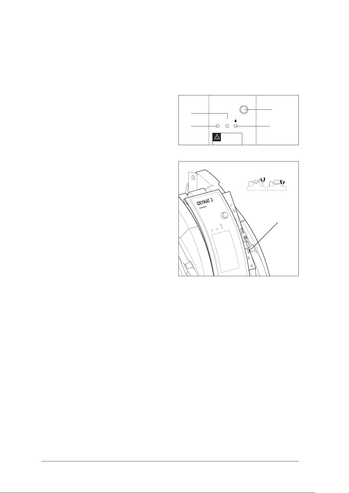
Visual and acoustic signals
from
6.1.1
6.1.2
6.1.3
Remedies
O2 concentration outside
tolerance range . . . . . . . . . . . . . . . . .
System pressure fault
. . . . . . . . . . . . . . . . . . . . . . 8
. . . . . . . . . . . . . . . . . . . . . 10
. . . . . . . . . . . . . . . . . . . . . 10
Checking the housing
Checking the coarse dust filter
Checking the power cord
Checking the fuse
Checking the main switch and
LED displays
Checking the dosage monitor for
leaks
Checking the flowmeter for leaks
Checking the operating hours
meter
Checking the O2 concentration
Checking the mains failure alarm
Checking the indirect
cator (yellow LED) with appliance
closed
Checking the indirect status
indicator (yellow LED) with the
appliance
System pressure test
Checking the O2 system for leaks
OXYMAT 3 . . . . . . . . . . . . . . . .
Alarms
Signal patterns
Deactivating the signal functions
. . . . . . . . . . . . . . . . . .
. . . . . . . . . . . . . . . . . . 8
. . . . . . . . . . . . . . . . . . . . . . 9
. . . . . . . . . . . . . . . . . . .
. . . . . . . . . . . . . 9
. . . . . . . . . . 9
. . . . . . . . . . . . . . . . . . . . .
. . . . . . . . . . . . . . . . . 10
status indi
open
. . . . . . . . . . . . . . . . . . . . . .
. . . . . . . . . . . . . . . . . . . . 22
. . . . . . . . . . . . . 27
10
-
19
19
27
3
4
5
8
9
7.
Repair information and repair instructions
7.1
General
7.2
Replacing the castors
7.3
Opening the appliance
7.4
Closing the
7.5
Replacing the compressor
(up to appliance no. 13350) . . . . . . . .
7.6
Replacing the compressor
(from appliance no. 13351 to 14999) .
7.7
Replacing the compressor
(from appliance no. 15000) . . . . . . . .
7.8
Replacing the operating hours meter
7.9
Replacing the circuit board
7.10
Replacing the fan
7.11
Replace adsorption containers
(Mac valves) . . . . . . . . . . . . . . . . . . .
7.12
Replace adsorption container
(plastic magnetic valve block) . . . . . . . .
7.13
Replace adsorption containers
(aluminum magnetic valve block) . . . . . .
7.14
Replace cover
7.15
Replacing the pressure reducer
7.16
Replacing the frame
(up to appliance no. 19999) . . . . . . . .
7.17
Replacing the frame
(from appliance no. 20000) . . . . . . . .
7.18
Replacing magnetic valves with valve block
(up to appliance no. 34999) . . . . . . . .
7.19
Replace magnetic valve block
8.
Spare parts
8.1 List of spare parts . . . . . . . . . . . . . . . 69
8.2 Maintenance set. . . . . . . . . . . . . . . . 72
9. Tools, testing equipment, disinfectants . . . . . 73
9.1 General tools and test equipment. . . . . 73
9.2 Special tools and test equipment . . . . . 73
9.3 Disinfectants . . . . . . . . . . . . . . . . . . 74
10. Technical Data. . . . . . . . . . . . . . . . . . . . . . . 75
10.1 Arrangement of the PCBs . . . . . . . . . . 76
11. Technical Changes . . . . . . . . . . . . . . . . . . . . 77
12. Repair and inspection log . . . . . . . . . . . . . . 78
13. Test report. . . . . . . . . . . . . . . . . . . . . . . . . . 79
. . . . . . . . . . . . . . . . . . . . . 28
. . . . . . . . . . . . . 28
. . . . . . . . . . . 29
appliance
. . . . . . . . . . . . . . . . . 53
. . . . . . . . . . . . . . . . . . . . . . . . .
. . . . . . . . . . . . 30
. . . . . . . . . 40
. . . . . . . . . . . . . . . 42
. .
28
30
33
36
. . . 39
43
46
49
. . . . . . 54
57
59
60
. . . . . . . 66
69
© Copyright Weinmann GmbH & Co. KG.
The content and presentation are copyright protected and may only be used by authorised Weinmann Service Partners in the
course of their service operations. The content must not be reproduced or passed on to third parties. The complete documents
must be returned on termination of the cooperation with Weinmann.
2
Page 3

Introduction
For decades, Weinmann has developed, manufactured and distributed equipment for oxygen therapy, inhalation therapy, sleep apnea therapy and
emergency medicine.
In 1982, Weinmann introduced the first oxygen
concentrator to the market.
Long-term oxygen therapy with an oxygen concentrator now has a firm place in the treatment of
chronic obstructive diseases of the respiratory
tracts. Many studies have proven that long-term
oxygen therapy can bring about a tangible improvement in life expectancy and quality of life.
The OXYMAT 3 oxygen concentrator from Weinmann is part of this therapy concept.
The aim of these service and repair instructions is
to familiarise you, as a knowledgeable expert, with
the OXYMAT 3 with regard to function, technology, servicing and repairs. In conjunction with the
training you have already received from Weinmann, you are now a "trained, qualified expert"
and are able to instruct your clients correctly, rectify
faults yourself, and carry out the functional checks
described in the instructions, as well as conduct
any repairs which may be necessary, as outlined
in these service and repair instructions.
In the event of a guarantee claim, OXYMAT 3 should
be returned to Weinmann.
In order to enable us to process any guarantee or
goodwill claims, please return the consumer's
proof of purchase (invoice) together with the appliance.
Repair and maintenance work must be carried out
only by Weinmann or by knowledgeable expert
staff.
You are responsible for any repairs performed by
yourself and for guaranteeing them!
Only original Weinmann spare parts should be used
for repair purposes.
Please remember:
Your customer trusts you and relies on your expertise, just as you rely on Weinmann.
Note:
The following information can be found in the description and operating instructions for OXYMAT 3:
• Safety instructions
• Installation
• Operation
• Hygienic preparation
• Warranty
3
Page 4
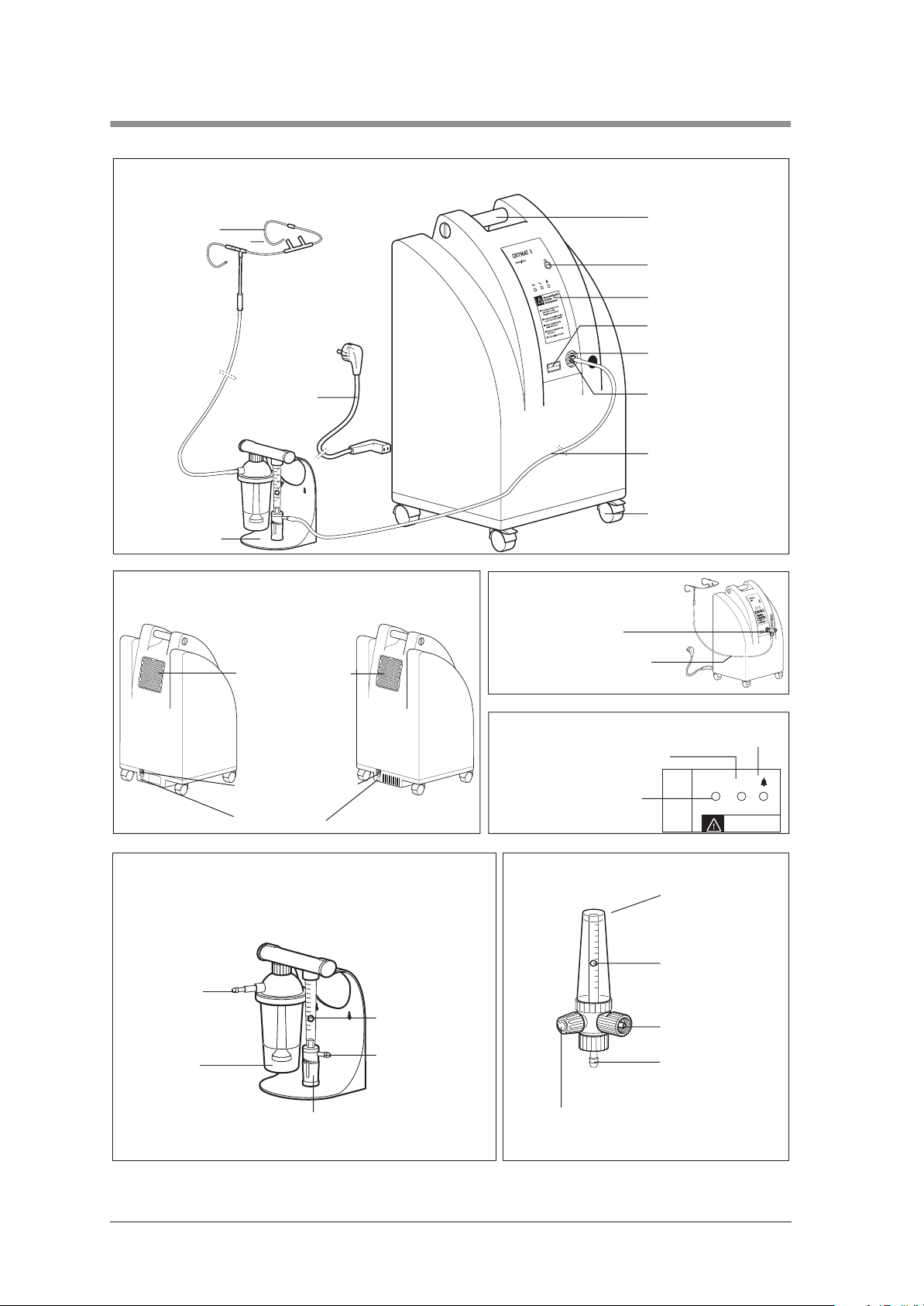
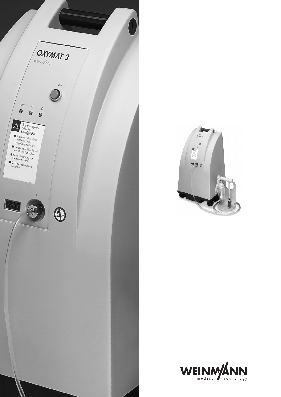
1. Overview
Front
(with dosage monitor)
12 Nasal cannula
11 Connecting tube
(3 m) for nasal
cannula
1 Handle for lifting or
moving
2 On/Off knob
3 Warning notices
4 Operating hours meter
5 Oxygen outlet
10 Power cord
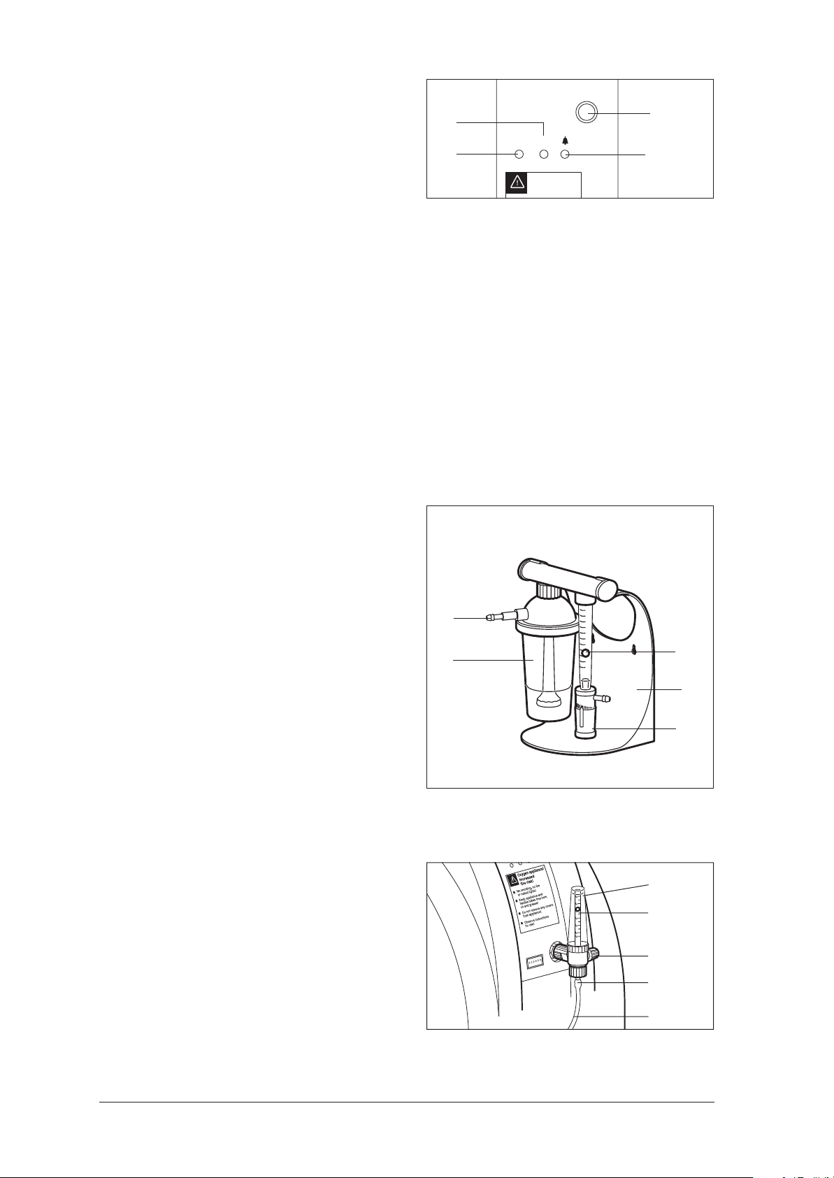
Dosage monitor
9
Back
up to appliance no. 19999 from appliance no. 20000
13 Coarse dust filter
14 Power cord socket
15 Fuse holder
Front
(with Flowmeter)
16 Flowmeter
17 Connecting tube
(10 m)
Indicators
19 Oxygen concentration status
indicator (yellow)
20 Power indicator (green)
6 Connecting nipple
with union nut (fitted)
7 Connecting tube
(20 m)
8 Castors with brake
18 Fault indicator (red)
O
O/I
2
Oxygen appliance!
Increased
Dosage monitor
26 Connection,
3 m hose to
nasal cannula
25 Humidifier
glass of
bubble
humidifier
4 Overview
21 Dosage unit (flowmeter)
0
,
5
0
,
4
0
,
3
0
,
2
0
,
1
5
,
0
24 Flow control knob
22 Ball, indicates
flow
23 Connection, long
tube to
OXYMAT 3 (20 m)
Flowmeter
16 Flowmeter
22 Ball, indicates
flow
28 Connection,
OXYMAT 3
29 Connection for
tubes
(3 m or 10 m)
27 Flow control knob
Page 5
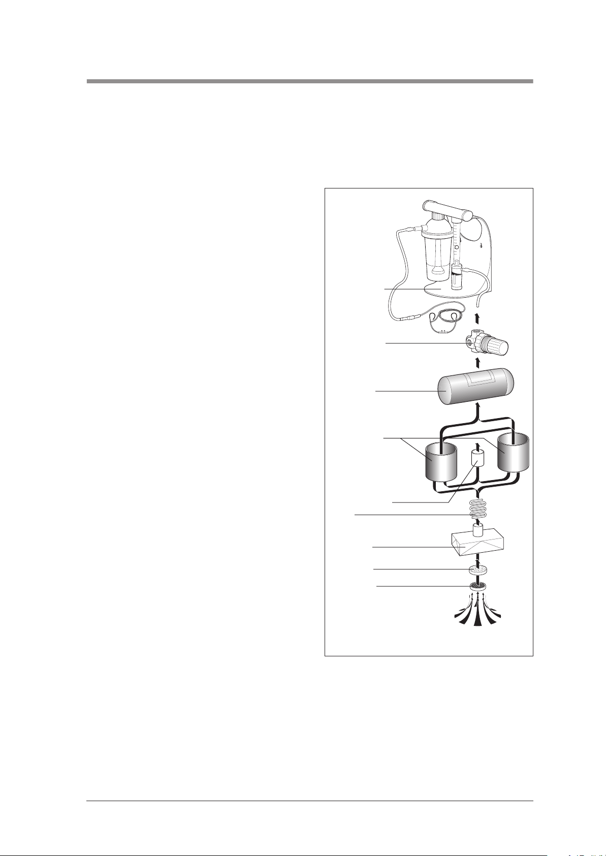
2. Functional description
OXYMAT 3 is a time-controlled appliance, i.e. the changeover time remains constant; only the pressure is
monitored.
Layout
The appliance essentially consists of three components:
• the compressor,
• the O2 system,
• the electronic/pneumatic control.
During operation, the compressor draws in ambient air via a coarse dust filter and a suction filter,
and passes the compressed air (approx. 1.7 bar
overpressure) into containers with molecular sieves
where the actual oxygen enrichment takes place.
The functional principle of molecular sieves is
based on their property of absorbing the nitrogen
contained in the air. The oxygen contained in the
air is then collected in the oxygen tank (further details can be found in the chapter “ The O2 enrichment process” on page 6).
The outlet pressure is regulated by a pressurereducer set to 0.6 bar.
The required quantity (flow) of oxygen is set on the
oxygen dosage control knob 24. Where a flowmeter is used, the flow is controlled via the flow
control knob 27. The flow is read at the top edge
of the flowmeter ball 22.
Every time it is switched on, the appliance control
system performs an internal self-test of the entire O2
system. This test takes about a minute. If the test detects an error in the O2 system that results in a drop
in the oxygen concentration, it activates the yellow
status indicator 19.
After the self-test, OXYMAT 3 switches to normal
operation. During normal operation the sequence
control constantly monitors the electrical and pneumatic circuits of the oxygen system.
Dosage monitor
Pressure-reducer
Oxygen tank
Container with
molecular sieve
Noise suppressor
Cooler
Compressor
Suction filter
Coarse dust
filter
5,0
4,0
3,0
2,0
1,0
0,5
Ambient air
In order to allow the process to run continuously, the containers operate alternately, i.e. before one container
is saturated with nitrogen, the system switches to the second container, which then continues with oxygen
enrichment. During this period, the first container is regenerated by a brief reduction in pressure, and at the
same time is flushed by a partial flow of enriched oxygen. This procedure is implemented cyclically at 7second intervals, thereby ensuring continuous oxygen enrichment of the inspiratory air.
Functional description 5
Page 6
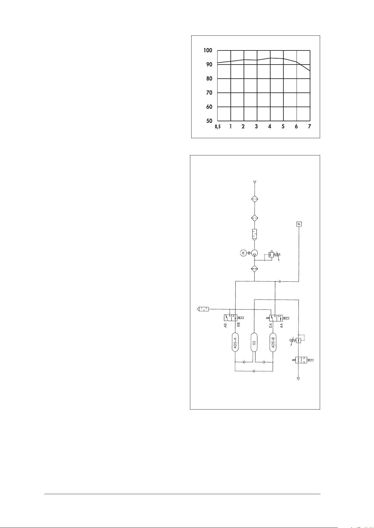
The level of oxygen concentration depends on the
set flow and is available within a few minutes.
The waste air is expelled to the rear via a noise
suppressor on the underside of the appliance.
The electronic control with microprocessor consists
of one circuit board. It is housed separately from
the oxygen system on the front panel.
The O2 enrichment process
The compressor draws the ambient air into the
housing via a coarse dust filter. Part of this air is
used to cool the compressor assembly. The other
part enters the compressor via the suction filter,
where it is compressed. A cooler reduces the temperature of the air. The compessed and cooled air
is then passed to the O2 system to enrich the oxygen.
Oxygen concentration
Flow [ l/min ]
Ambient air
The adsorption containers (ADS containers) are
alternately filled with compressed air in fixed
cycles, then regenerated by expanding the
compressed air and flushing with oxygen.
At the end of each enrichment, a pressure of
around 1.7 bar will have built up in the currently
active container.
After 7 seconds, the magnetic valves are alternately triggered by the electronic control and
switch between the two ADS containers.
Of the valves in the two ADS containers, one is
open and the other closed during operation.
Once the changeover time has been reached,
pressure compensation is implemented between
the two ADS containers. During pressure compensation, both valves are open for approximately
1 second.
The actual process of oxygen enrichment takes
place in the ADS containers. A molecular sieve
adsorbs the nitrogen from the air, thereby increasing the proportion of oxygen by volume.
As soon as the pressure in the ADS container has
risen sufficiently, air enriched with oxygen flows
into the oxygen tank at the other end of this container via the non-return valve.
Noise suppressor
Magnetic valves
Non-return valves
Suction filter
Compressor
Cooler
ADS container
Oxygen tank
Coarse dust filter
ADS container
Flushing nozzle
Throttle
Shutoff valve
outlet
2
O
Pressure sensor
Pressure reducer
6 Functional description
Page 7

Part of the oxygen flows via the flushing nozzle into
the other ADS container for flushing.
During the oxygen enrichment process, the area
where adsorption of the nitrogen occurs will shift
from the beginning of the ADS container towards
the end. Before reaching the end of the container,
the pressure between the two ADS containers is
compensated via the pressure compensating
valve. Parallel to this, the pressure escapes via the
noise suppressor and the other ADS container is
opened. The same procedure then takes place
there.
Via pressure compensation, the remaining oxygen
passes to the other ADS container, compression
energy is saved, and blow-off noise is reduced.
The nitrogen adsorbed in the first ADS container is
desorbed as a result of the pressure drop when the
valve is opened and is expelled via the noise
suppressor.
Displays and alarms
In order to attain adequate desorption of the molecular sieve, part of the oxygen extracted in one
ADS container is continuously passed to the other
ADS container via the flushing nozzle.
The oxygen stored in the oxygen tank at an overpressure of up to 1.7 bar is reduced to 0.6 bar via
the pressure-reducer.
The pressure sensor monitors this system pressure.
If the pressure falls below 0.5 bar or rises above
2.5 bar, the system activates visual and acoustic
alerts.
At an overpressure of around 0.6 bar, the oxygen
flows towards the outlet of the appliance.
The prescribed flow is set on the dosage monitor
or on the flowmeter. It then flows to the patient via
the nasal cannula.
• If a leak that is likely to cause a drop in the oxy-
gen concentration occurs after the internal self-
test, this situation is indicated immediately by a
visual warning signal (yellow lamp).
• If the compressor output falls off, a visual alarm
signal is displayed (red lamp flashes) and an
acoustic warning (intermittent tone) sounds.
Further information on displays and alarms can be found in Chapter “6.1 Visual and acoustic signals from
OXYMAT 3” on page 19“.
• The green lamp indicates that the system is operational.
• In the event of a power failure, an intermittent
warning signal will sound and the red lamp
will flash. The green lamp is not illuminated.
Functional description 7
Page 8

3. Servicing
3.1 General
• Important!
Enter the operating hours of OXYMAT 3 and the
oxygen concentration in your service record
(see page 78).
• The number of operating hours can be read
from the operating hours meter 4 on the front of
the device.
• As a precautionary measure, we recommend
that the OXYMAT 3 be serviced once a year
or every 5,000 operating hours.
• After each servicing, a functional check should
be carried out (see "5. Functional check" on
page 10).
Note: Dark discoloration of the intake filter 30 does
not mean that its flow characteristics are impaired,
provided its operating hours do not exceed
5,000 h; an exception applies if the device is operated in a very dusty environment.
3.2 Implementation
Servicing the OXYMAT 3 involves changing the coarse dust filter and the suction filter and performing a final
check (see "5. Functional check" on page 10).
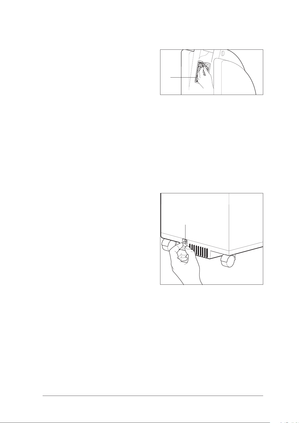
The filters are located on the back of the appliance.
1. Detach the coarse dust filter 13 from the
service flap 38.
13
2. Release the lock on the service flap 38 and
remove the latter from the appliance.
When removing the suction filter, please proceed
with caution, since the connector and tube may be
torn off if the suction filter is handled carelessly.
3. You will find a black clip in the recess to the
left of the suction filter. Use your fingers or an
object to press against this clip to prevent it
from being pulled out as well.
4. Pull the suction filter 30 off the connector 71
without twisting. The suction filter must not be
twisted, as the connector could become
detached from the tube.
5. Connect the new filter 30 to the connector.
6. Clean the service flap 38 and insert it.
7. Clip a new coarse dust filter 13 into the service
flap 38.
38
71
30
8 Servicing
Page 9

3.3 Disposal
Do not dispose of the unit with domestic waste. For proper disposal of the device and its components, please contact a certified waste disposal site for electronic goods. Ask your Environmental
Officer or local council for the address. Appliance packaging (cardboard and inserts) may be disposed of in the paper recycling bin.
4. Hygienic Preparation
4.1 No change of patient
Proceed as described in the operating instructions
for the OXYMAT 3.
4.2 Change of patient or reuse
• Dispose of extension tubes and nasal cannulas, and replace with new parts.
• Dispose of coarse dust filter and suction filter,
and replace with new parts.
• For the bubble humidifier, please observe the
separate operating instructions.
• Wipe housing and power cord with TERRALIN
disinfectant.
• Clean inside of housing with vacuum cleaner,
clean any particularly dirty parts with household cleaner (to open and close the appliance, see sections 7.3 and 7.4 on page 29
and page 30).
Hygienic Preparation 9
Page 10

5. Functional check
5.1 General
• Should you discover any faults or deviations
from the set values during your functional
check, OXYMAT 3 must not be used again until the faults have been rectified.
• The possible causes underlying the fault and
how to rectify them are outlined in Chapter “6.
Troubleshooting” on page 19.
Please use the following equipment to carry out the functional check:
• Oxygen measuring device,
• Filled oxygen cylinder with adjustable pressure reducer (e.g. HIT,WM 33100),
• Respiratory tubes WM 5726 and WM 5772.
• For environmental reasons a capacitor backup unit has been installed instead of a battery
to serve the power failure alarm function.
As soon as OXYMAT 3 is operational, the capacitor is recharged. Charging takes approximately 5 minutes.
If the device has been out of service for some
time, an alarm cannot be triggered until the device has been operational for at least 5 minutes.
5.2 Intervals
A final check must be performed on the appliance:
• after every service;
• after every repair.
5.3 Implementation
5.3.1 Checking the housing
Check the housing to determine its general
condition.
• Dirt can be wiped off with a damp cloth. The
all-purpose cleaner WM 14937 is also very
suitable.
• If you want to use a disinfectant, we recommend TERRALIN.
10 Functional check
• If the housing is defective, replace it (see "7.3
Opening the appliance" on page 29) and
„7.4 Closing the appliance“ auf Seite 30.
• If the frame is defective, please replace it (see
"7.16 Replacing the frame (up to appliance
no. 19999)" on page 57).
Page 11
5.3.2 Checking the coarse dust filter
Check the coarse dust filter 13 to determine its general condition:
1. Unclip the coarse dust filter from the back of
OXYMAT 3.
2. If the filter is dirty, clean it. As a general rule,
the filter should be freed from dust once a
week (either by tapping or vacuuming).
3. If the filter is defective, replace it.
13
5.3.3 Checking the power cord
1. Check the power cord 10.
Make sure that
– the insulation is undamaged,
– the cable is undamaged,
– none of the contacts are wobbly.
2. If any of these requirements are not satisfied,
replace the power cord 10.
5.3.4 Checking the fuse
The fuse holder 15 can be found on the rear of the appliance beneath the power socket 14.
1. Pull the power cord 10 from the socket and
from the device.
2. Press the side tabs on the fuse holder 15 together and pull out the fuse holder.
3. Check that the correct fuses are installed.
There should always be two fuses installed:
A mains fuse and a spare fuse.
The fuses 39 should carry the following label:
DIN EN 60127-T 2.5 A H 250 V.
4. If necessary, replace the defective or missing
fuses.
5. Push the fuse holder 15 into the housing until it
locks home.
15
5.3.5 Checking the main switch and LED displays
1. Connect the power cord 10 to OXYMAT 3
and to a wall socket.
2. Connect the dosage monitor or the flowmeter
to the oxygen outlet 5.
Functional check 11
Page 12
3. Switch on the OXYMAT 3 at the On/Off
knob 2. The following LED displays will appear:
– The power indicator (green LED) 20 lights
up.
– The fault indicator (red LED) 18 and status
indicator (yellow LED) 19 light up briefly.
Important
The program then makes an internal check for
leaks:
– Pressure is built up within 20 seconds. The
green operating indicator 20 flashes light/
dark.
– Then the compressor is switched off and the
existing pressure is monitored for about 20
seconds. If there is a fault and the pressure
drops, the yellow status indicator 19 lights
up.
– Finally the system is vented so that the com-
pressor can start up again without any
back-pressure.
5.3.6 Checking the dosage monitor for leaks
19
20
O/I
Oxygen appliance!
Increased
fire risk!
O/ I
2
O
2
18
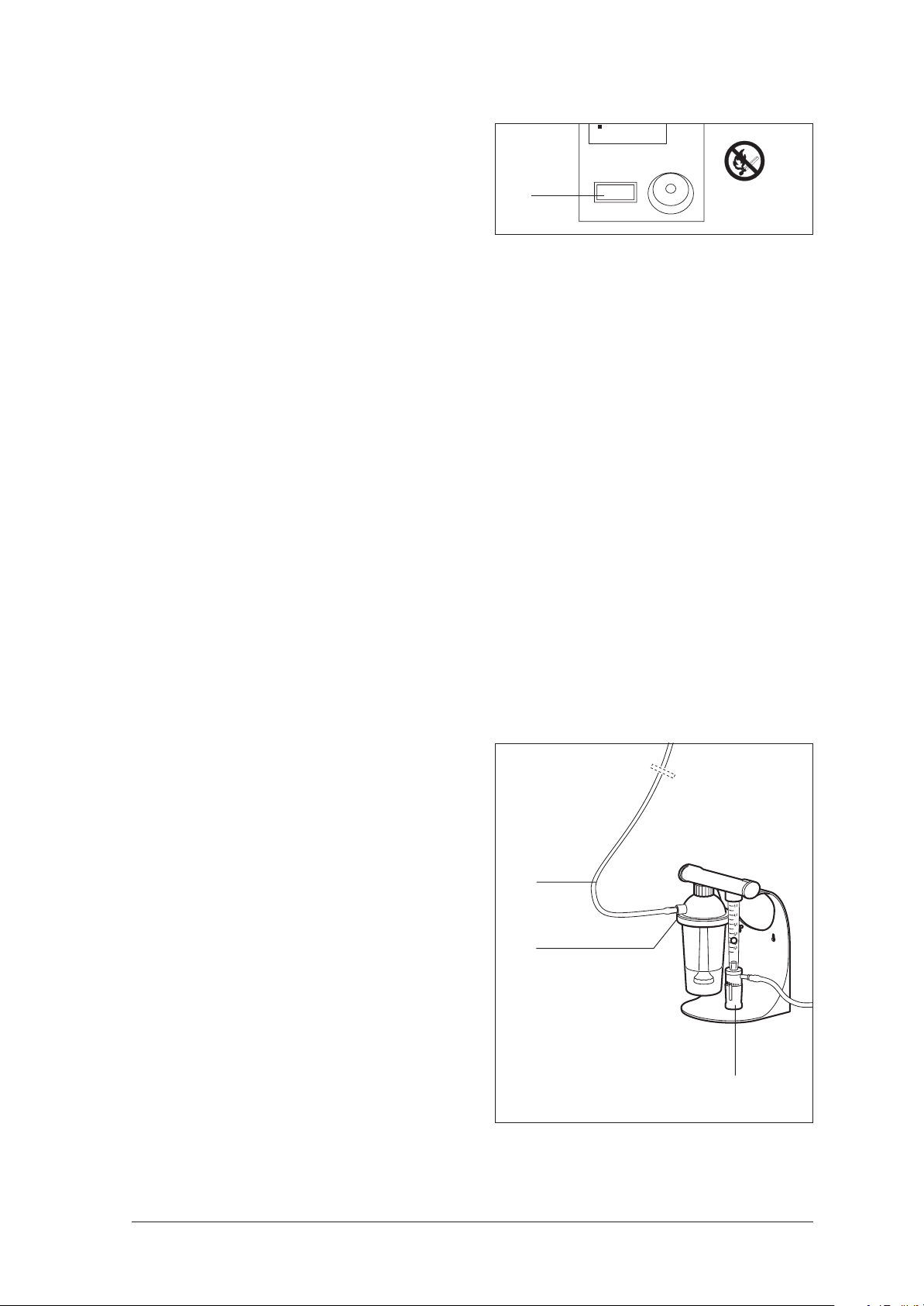
1. Check the screw connections between the humidifier glass/cap and humidifier/dosage
monitor to verify that they are firmly seated. If
necessary, re-tighten the connections by hand.
2. Set a flow of 4 l/min on the flow control
knob 24 for oxygen dosage.
3. To check the dosage monitor 9 for leaks,
– bend the 3 m tube 11
– or pull the 3 m tube 11 from the connection
of the bubble humidifier 25 and hold the
connection 26 closed.
If the ball 22 sinks all the way to the bottom,
there are no leaks in the dosage monitor system.
4. In the event of leaks, change the sealing rings
on the humidifer.
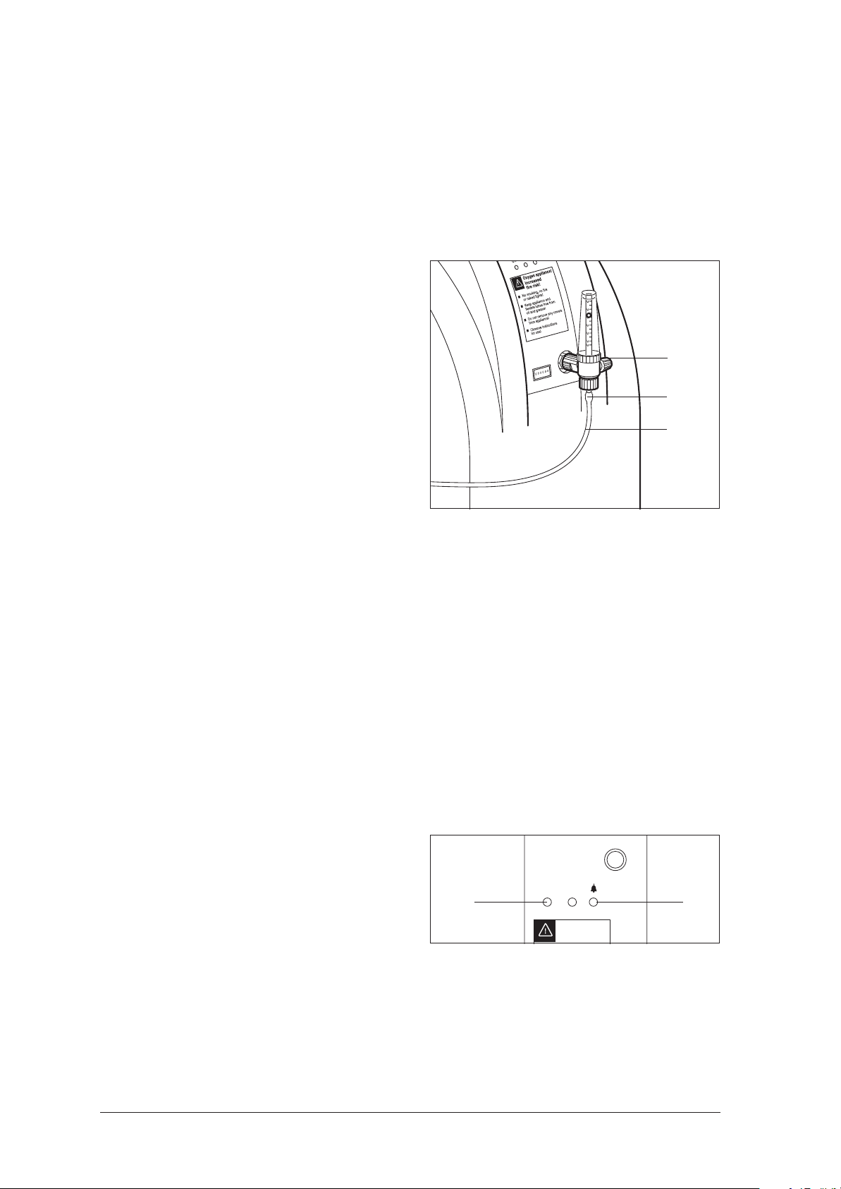
5.3.7 Checking the flowmeter for leaks
1. Set a flow of 4 l/min on the knob 27.
2. To check the flowmeter 16 for leaks:
– Bend the connection tube 17
– or pull the tube 17 from the connection of
the flowmeter and hold the connection 29
closed.
If the ball 22 sinks all the way to the bottom,
there are no leaks in the flowmeter.
3. In the event of leaks, change the sealing rings
on the flowmeter.
26
25
0
,
5
0
,
4
0
,
3
0
,
2
0
,
1
5
,
0
22
9
24
16
22
27
29
17
12 Functional check
Page 13
5.3.8 Checking the operating hours meter
Check that the red minute counter on the operating
hours meter 4 is incremented every 6 minutes.
5.3.9 Checking the O2 concentration
Leave the OXYMAT 3 to run for at least 10 minutes
before starting the measurement.
Before you check the oxygen concentration on the
OXYMAT 3, you must first calibrate the oxygen
measuring device (e.g. OXYcontrol WM 13550).
For this purpose, you will need the respiratory tube
WM 5726 and an oxygen cylinder with an adjustable pressure reducer (e.g. WM 33100).
Caution !
Please observe the instructions for handling oxygen!
Important!
Before calibrating the oxygen sensor for the first
time, the sensor must be stored in ambient air for
at least 15 minutes (refer to instructions for use of
the sensor).
Observe instructions
for use!
4
000000
How to calibrate the oxygen sensor:
1. Connect the oxygen measuring device to the
pressure reducer of the oxygen cylinder using
the respiratory tube WM 5726.
2. Slowly open the cylinder valve. One revolution
is sufficient!
3. Set a flow of 4 l/min at the pressure reducer.
4. Leave the oxygen measuring device (e.g.
OXYcontrol) flowing for approximately 2 minutes,
until the displayed oxygen level remains steady.
5. Set a value of "100" using the calibration
knob.
6. Close the cylinder valve again.
The oxygen measuring device is now calibrated
and you can check the oxygen concentration on
OXYMAT 3.
Please remember that OXYMAT 3 must have already
been operational for at least 10 minutes.
When operating with a dosage monitor:
Important!
It is vital that you empty the humidifier glass 25 of the
bubble humidifier; otherwise, the oxygen sensor of
the oxygen measuring device will be damaged.
7. Connect the oxygen measuring device:
– To do so, remove connecting tube 11 from
connection 26 of the dosage monitor and
use breathing tube WM 5772 to make a
connection between connection 26 and the
oxygen measuring device;
or
– Unscrew the bubble humidifer (sterile water
system) from the dosage monitor and attach
the connecting tube to the OXYcontrol at
this point with the union nut.
8. Using the flow control knob 24, set a flow of
4 l/min.
11
26
24
Functional check 13
Page 14
9. After waiting for a short while, read the oxygen concentration from the oxygen measuring
device.
It should be between 90 and 95 % by volume.
10. Re-connect the connecting tube 11.
11. If the O2 concentration is outside the tolerance
range, proceed as described in “6.3 O2 concentration outside tolerance range” on
page 27.
When operating with a flowmeter:
7. Connect the oxygen measuring device:
– To do this, remove connecting tube 17 from
connection 29 of the flowmeter and use
breathing tube WM 5772 to make a connection between connection 29 and the
oxygen measuring device;
or
– Unscrew the union nut from the flowmeter
and attach the connecting tube to the
OXYcontrol at this point with the union nut.
8. Using the flow control knob 27 set a flow of
4 l/min.
9. After waiting for a short while, read the oxygen concentration from the oxygen measuring
device.
27
29
17
It should be between 90 and 95 % by volume.
10. Re-connect the connecting tube 17.
11. If the O2 concentration is outside the tolerance
range, proceed as described in “6.3 O2 concentration outside tolerance range” on
page 27.
5.3.10 Checking the mains failure alarm
Note:
As power is supplied to the alarm function via a capacitor, the OXYMAT 3 should first be operated for 5 minutes
to allow the capacitor to charge.
1. Pull the power cord from the socket or from the
device.
2. Check whether the following displays and
alarms occur:
– Acoustic: The device emits a continuous
tone.
– Optical: The red fault indicator 18 lights up;
the green power indicator 20 is off.
3. Re-make the connection to the mains.
Now:
– The acoustic alarm should be silenced.
– The red fault indicator 18 should go out.
O
20 18
O/I
Oxygen appliance!
Increased
fire risk!
– The green power indicator 20 should be
on.
– The appliance should start up.
O/ I
2
14 Functional check
4. Switch off the appliance at the On/Off knob 2.
Page 15

5.3.11 Checking the indirect status indicator (yellow LED) with appliance closed
The purpose of this check is to establish whether the status indicator that warns if a leak that is likely to cause
a drop in the oxygen concentration is working properly. This is done by an internal program that creates an
artificial leak which results in the alarm being triggered.
1. Switch on the OXYMAT 3 at the On/Off
switch 2.
An internal leak test will run for about 1 minute.
19
The green operating indicator 20 flashes while
this is in progress.
20
2. With the appliance running, set a flow of
4 l/min at the top of the ball.
To start the test program, proceed as follows:
3. Remove power cord 10 from the wall socket or
the appliance.
4. Wait for the acoustic power failure alarm to
sound (two groups of five tones – – – – –).
5. Switch off the OXYMAT 3 at the On/Off
switch 2. Do not connect the power cord
again.
6. Switch OXYMAT 3 on again at On/Off
switch 2.
11. Check that the yellow status indicator 19 is on
while this is happening.
If the status indicator does not light up, either:
– you have not set the flow to exactly 4 l/min
or
– the status indicator is faulty.
12. Switch off the OXYMAT 3 at the On/Off
switch 2, then switch it on again.
The test program is now deactivated and the
OXYMAT 3 is in normal operating mode.
7. Wait for the acoustic power failure alarm to
sound again (two groups of five tones
– – – – –).
8. Switch off the OXYMAT 3 at the On/Off
switch 2.
The yellow status indicator 19 must now light
up. If it does not, repeat the procedure.
9. Connect the power cord again.
10. Switch on the OXYMAT 3 at the On/Off
switch 2.
The following LED indicators appear:
– green operating indicator 20 lights up
– red fault indicator 18 lights up briefly
– yellow status indicator 19 lights up briefly.
O/I
Oxygen appliance!
Increased
fire risk!
O/ I
2
O
2
18
The program then runs an internal leak check
routine:
– pressure is built up within 20 s. The green
operating indicator 20 flashes.
– the pressure is checked for about 20 s with
the compressor switched off.
An artificial leak is created in the OXYMAT 3, and
this results in the oxygen concentration falling below 82 %.
Functional check 15
Page 16
5.3.12 Checking the indirect status indicator (yellow LED) with the appliance open
Note:
Not necessary as part of a normal functional check or service.
The purpose of this check is to establish whether the status indicator that warns if a leak that is likely to cause
a drop in the oxygen concentration is working properly. This is done by an internal program that creates an
artificial leak which results in the alarm being triggered. If the appliance is open (e.g. for repair work) you
can start this test program with switch S5 on the printed circuit board.
1. Switch on the OXYMAT 3 at the On/Off
switch 2.
An internal leak test will run for about 1 minute.
19
The green operating indicator 20 flashes while
this is in progress.
20
2. With the appliance running, set a flow of
4 l/min at the top of the ball.
To start the test program, proceed as follows:
3. Switch off the OXYMAT 3 at the On/Off
switch 2.
4. Open coding switch S5 on the printed circuit
board.
5. Switch on the OXYMAT 3 at the On/Off
switch 2.
The following LED indicators appear:
– green operating indicator 20 lights up
– red fault indicator 18 lights up briefly
O
O/I
– yellow status indicator 19 lights up briefly.
The program then runs an internal leak check
routine:
– pressure is built up within 20 s. The green
operating indicator 20 flashes.
– the pressure is checked for about 20 s with
the compressor switched off.
O/I
Oxygen appliance!
Increased
fire risk!
O/I
2
O/ I
2
O
2
18
S5
An artificial leak is created in the OXYMAT 3, and
this results in the oxygen concentration falling below 82 %.
6. Check that the yellow status indicator 19 is on
while this is happening.
If the status indicator does not light up, either:
– you have not set the flow to exactly 4 l/min
or
– the status indicator is faulty.
7. Switch off the OXYMAT 3 at the On/Off
switch 2.
8. Close coding switch S5 on the printed circuit
board.
The test program is now deactivated and the
OXYMAT 3 is in normal operating mode.
9. Close the appliance (see "7.4 Closing the
appliance" on page 30).
16 Functional check
Page 17
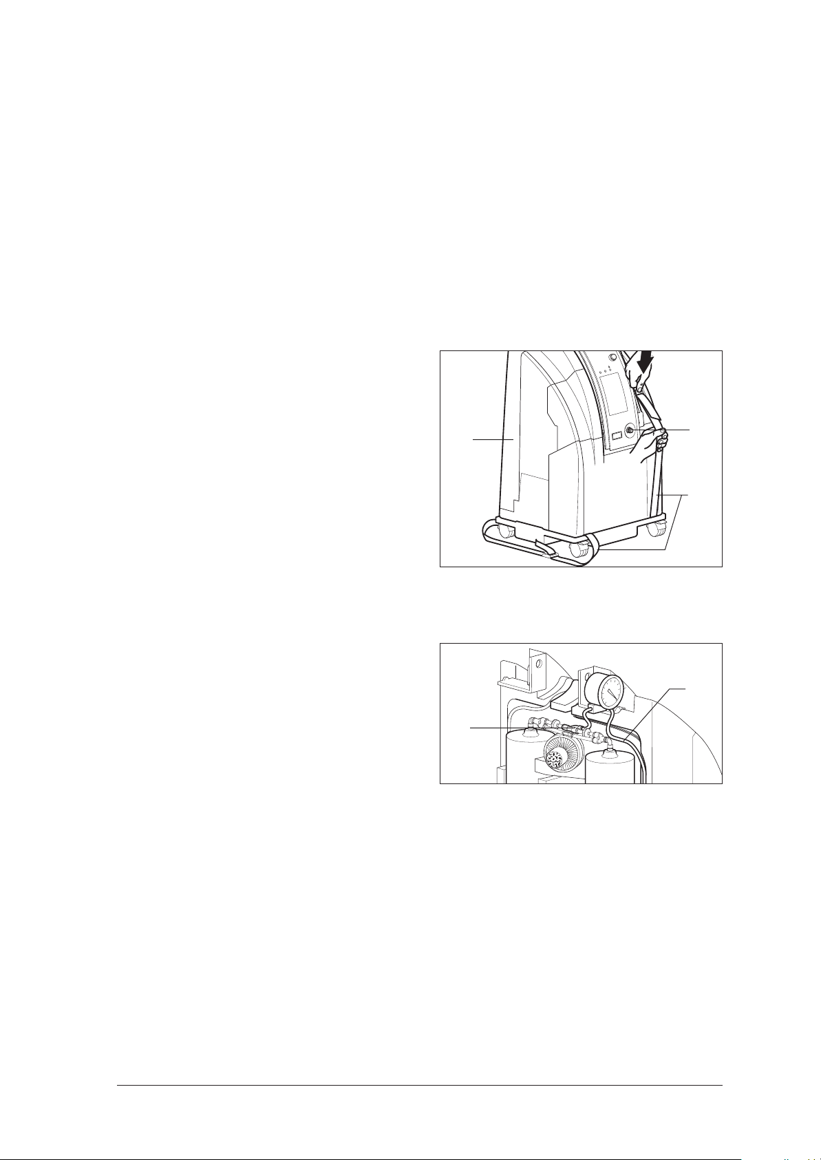
5.3.13 System pressure test
General
The system pressure should only be tested if there is a fault in the appliance.
Fitting the test pressure gauge
1. Connect the test pressure gauge inlet directly
to the oxygen outlet 5.
If your pressure gauge also has an outlet, close
it (e.g. with your thumb).
2. Open the appliance housing (see "7.3 Opening the appliance" on page 29).
3. Open the strap system 42 without pulling the
strap out of its buckle.
4. Carefully remove foam section 44.
5. To prevent the ADS containers from slipping
out, lay the strap system 42 over the remaining
foam sections and gently tighten it.
44
I
/
O
2
O
/I
O
O
2
0000
0
0
5
To make fitting easier, the test pressure gauge is
not fitted directly to the inlet of the O2 tank, but
before the 6 mm diameter tube 56 which leads
directly to the O2 tank.
6. At the T-connector 74, push back the sleeve of
the elbow connector and remove the tube 56.
7. Push the tube of the test pressure gauge firmly
into the elbow connector.
8. Push the tube 56 into the free inlet of the test
pressure gauge.
Pressure test
Oxygen outlet
1. Plug the power cord 10 into the appliance and
insert the mains plug in a wall socket.
2. Switch the OXYMAT 3 on.
3. After 10 minutes, attach the pressure gauge to
the oxygen outlet 5.
4. Read off the pressure.
The reading must be in the range
0.6 bar ± 0.1 bar (at sea level).
5. Rectify any discrepancies you find (see "6.2
Remedies" on page 22).
42
56
74
6. Switch the appliance off, then remove the
mains plug from the wall socket and the power
cord from the appliance.
7. Remove the pressure gauge.
8. Perform a functional check (see "5. Functional
check" on page 10).
Functional check 17
Page 18

O2 tank inlet
9. Attach the dosage unit 21 or the flowmeter 16.
10. Plug the power cord 10 into the appliance and
insert the mains plug in a wall socket.
11. Switch the OXYMAT 3 on.
Caution!
Risk of injury or death!
Beware of live or moving components.
12. Set the flow to 4 l/min.
13. After 10 minutes, read off the pressure on the
pressure gauge.
The reading must be in the following range:
At the O2 tank inlet:
min. 1.2 + 0.3/- 0.2 bar to
max. 1.65 bar + 0.3/- 0.2 bar
at 4 l/min (at sea level).
Rectify any discrepancies you find(siehe „6.2
Remedies“ auf Seite 22).
5.3.14 Checking the O2 system for leaks
14. Switch the appliance off, then remove the
mains plug from the wall socket and the power
cord from the appliance.
15. Remove the dosage unit 21 or flowmeter 16
from the appliance.
16. Remove the pressure gauge.
17. Attach the tube 56.
18. Slacken the strap system.
19. Carefully insert the foam section 44 and tighten the straps again.
20. Close the appliance (see "7.4 Closing the
appliance" on page 30).
21. Perform a functional check (see "5. Functional
check" on page 10).
General
A check for leaks should only be made if there is a
problem with the appliance.
Method
Soap all connections between the compressor exit,
the pressure equalization system (tubes, exit) and
the shutoff valve after the pressure reducer.
18 Functional check
Page 19

6. Troubleshooting
6.1 Visual and acoustic signals from OXYMAT 3
6.1.1 Alarms
The following appliance states trigger an alarm:
1. Power failure
2. Overheating
3. Memory error
4. Under-pressure
5. Over-pressure
6. Implausible pressure measurement
7. Leak in O2 system
1. Power failure
The energy for a power failure alarm is supplied by
a capacitor back-up unit. If the capacitor back-up
unit is fully discharged, the power failure alarm is
not available for the first minute after switching on
the OXYMAT 3 until the back-up unit has charged
up again.
2. Overheating
A temperature sensor is mounted on the printed circuit board. If the temperature rises above 60 °C
(± 2.5 °C), an alarm is given and at the same time
the compressor is switched off. The compressor remains switched off as long as the temperature
alarm is activated. The cause may for example be
a malfunction of the fan.
3. Memory error
Every time the appliance is switched on, the
EEPROM is first read out. Among other things, this
contains the operating cycles for the valves and the
calibration data for the temperature sensor. A plausibility check is performed on the data read out.
If a memory error occurs:
– default values (basic settings) are read from
the program memory and used to start the
control program;
– the memory error alarm is activated;
– after every alarm cycle a fresh attempt is
made to read the EEPROM;
– after a successful read attempt the alarm is
terminated.
4. Under-pressure
This alarm is activated if the pressure sensor at the
inlet to the O2 system measures a pressure lower
than the required operating pressure.
5. Over-pressure
This alarm is activated if the pressure sensor at the
inlet to the O2 system measures a pressure higher
than the required operating pressure.
6. Implausible pressure measurement
Since the OXYMAT 3 has a time control, there
must be a defined pressure pattern over time. This
pressure pattern is measured by the pressure
sensor and analyzed by the appliance software. If
necessary an alarm is activated.
7. Leak in O2 system
Every time the appliance is switched on, the control system runs a leak test on the entire O2 system.
If a leak is found, the yellow status indicator 19 is
switched on, as sooner or later this leak in the O2
system may result in the oxygen concentration at
the outlet falling below 82 %.
During the leak test the green power indicator 20
flashes.After the leak test the OXYMAT 3 switches to
normal operating mode.
If the leak test is not successfully completed within
one minute, the control system stops the test cycle
and switches on the yellow status indicator 19 to
indicate an operating fault. The cause of the leak
must now be identified.
No further test for leaks is performed during normal
operation.
Troubleshooting 19
Page 20

6.1.2 Signal patterns
The alarm signal patterns are in accordance with EN 475 (see Table of Signal Patterns). To make it possible
to distinguish the alarm sources, this standard assigns specific signal patterns to individual error situations
(see Table of Error Situations).
Since it is possible that two or more errors may occur at the same time, the alarms are weighted by the
software and the appropriate alarm pattern is output. For example: if under-pressure and overheating occur
simultaneously, the alarm pattern for overheating is output (see Table of Alarm Situations).
Table of Alarm Situations:
Appliance Status
Power failure
Overheating
Implausible
pressure reading
Memory error
Under-pressure
Over-pressure
O2 status
Release after
x minutes
1 minute after
cold start
Immediately after
switching on
1 minute after
end of leak test
Immediately after
switching on
1 minute after
end of leak test
1 minute after
end of leak test
Test immediately
after switching on
Pattern of alarm
signal indicators
Buzzer: A
Red LED: A
Yellow LED: off
Green LED: off
Buzzer: A
Red LED: A
Yellow LED: off
Green LED: on
Buzzer: A
Red LED: C
Yellow LED: off
Green LED: on
Buzzer: B
Red LED: B
Yellow LED: off
Green LED: on
Buzzer: C
Red LED: C
Yellow LED: off
Green LED: on
Buzzer: C
Red LED: D
Yellow LED: off
Green LED: on
Buzzer: off
Red LED: off
Yellow LED: on
Green LED: on
Classification of
Weighting
1 High priority
1 High priority
2 High priority
3 High priority
4 High priority
5 High priority
Is indicated
independently by
the yellow LED
signal patterns
under EN 475
Low priority
Note:
The green power indicator 20 is not an alarm signal indicator. Its status is only given here for completeness’
sake.
20 Troubleshooting
Page 21

The signal patterns for the buzzer consist of 2 identical pulse sequences, repeated every 10 seconds. Each
pulse sequence consists of 5 individual pulses (see Table of Signal Patterns).
Table of Signal Patterns:
Buzzer pattern
for one pulse
sequence
Pulse duration / ms
(= buzzer on)
Pulse interval/ ms
(= buzzer off)
Pulse interval
between 3rd and
4th pulse / ms
Graphic representation
A 150 100 500 — — — — —
B 150 10 320 — — — — —
C 150 0 300 ——— ——
Flashing pattern
for
red LED
Flashing
frequency / Hz
On time / ms Off time / ms Graphic representation
A 1.43 200 500 — —
B 1.43 400 300 —— ——
C 2.5 80 320 – –
D 2.5 240 160 — —
6.1.3 Deactivating the signal functions
The signal functions can be deactivated by means of the switches S2, S3, S4 and S5 on the printed circuit
board. To see where the switches are located on the PCB, consult the illustrations in Section “10.1 Arrangement of the PCBs” on page 76.
Coding switch Open Closed
S2
S3
Power supply for power failure alarm
deactivated.
Buzzer deactivated. Buzzer activated.
Alarm suppression during warming-up
S4
phase deactivated
(i.e. alarm function activated).
S5
Tip:
Activates program for checking status
indicator
Power supply for power failure alarm
activated.
Alarm suppression during warming-up
phase activated
(i.e. alarm function deactivated).
Normal operation
For fault-finding purposes it can be useful to open coding switch S4. This enables the alarms immediately on
completion of the leak test.
Troubleshooting 21
Page 22

6.2 Remedies
Fault Cause Localisation Remedy
No motor noises,
power indicator does
not light up, mains
failure alarm sounds.
No power.
Faulty fuse.
Check mains lead for
secure connection.
If applicable, check
whether power is available
at the mains (e.g. with a
lamp).
Replace fuse 39 (see "5.3.4
Checking the fuse" on
page 11).
A spare fuse can be found
in the fuse box.
Power indicator fails to
illuminate, no acoustic
alarm.
No flow at nasal
cannula, although
there is flow at the
appliance outlet. In
such cases, the
appliance does not
emit an alarm.
After running for a
long period,
appliance emits
intermittent acoustic
warnings and red fault
indicator flashes;
no flow.
After running for a
long period,
appliance emits
intermittent acoustic
warnings and red fault
indicator flashes.
Power cord damaged. Replace power cord.
Capacitor for mains
failure alarm is
completely
discharged.
Tube connections
interrupted.
Oxygen distributor in
bubble humidifier
blocked.
Motor compressor not
rotating.
Crank mechanism stiff,
motor circuit-breaker of
compressor is
activated.
Appliance too hot,
coarse dust filter
blocked.
Leak at compressor
outlet port elbow
connector
Suction filter blocked.
Overtemperature of
60 °C ± 2.5 °C.
Disconnect tube from inlet of
dosage monitor; check
whether flow is escaping
from the tube.
Loosen union nut of bubble
humidifier; the ball should
then rise.
Leave the appliance to run
for 5 minutes.
Seal all connection and
sealing points from the
appliance outlet to the inlet
of the dosage monitor.
Clean or replace the
oxygen distributor.
Capacitor incorrectly
connected or not connected
at all. Connect the
capacitor correctly
(7.5, page 30).
Check the voltage supply at
the motor. Motor defective:
Replace the compressor
(7.5, page 30).
Compressor defective:
Replace compressor
(7.5, page 30).
Clean or replace coarse
dust filter.
(3.2, page 8).
Replace parts (7.5,
page 30)
Replace suction filter.
(3.2, page 8).
Check fan
(7.10, page 42).
22 Troubleshooting
Page 23

The following faults are based on a defective circuit. They occur with the compressor and fan running.
Caution !
Always pull out the mains plug before working on electrical components.
Remember that all coding switches on the circuit board must be closed during normal operation.
Fault Cause Localisation Remedy
After switching on, first of all
After running for a
long period,
appliance emits
intermittent acoustic
warnings and red
fault indicator
flashes.
Memory failure.
the EEPROM is read. In the
event of a memory failure,
an alarm is issued and it is
then re-read. If this readout
attempt is successful, the
fault will be cleared. If not,
the circuit board should be
replaced.
(7.9, page 40).
Blow-off noises on
compressor
(overpressure valve
activated).
Connectors X10 and/
or X11 have worked
loose.
Inadequate voltage
supply to magnetic
valves.
No voltage supply to
magnetic valves.
Fuse F1 tripped.
Green LED is illuminated and
an acoustic pressure alarm
sounds.
See above.
See above.
Green LED not illuminated,
mains failure alarm.
Re-make the connection
(7.9, page 40).
Ensure that the mains
voltage is at least 207 V.
Replace fuse F2
(7.9, page 40).
Replace fuse F1
(7.9, page 40).
Overpressure
alarm
(acoustic alarm,
red LED 18 flashing
2.5 times per
second).
No overpressure
alarm, even though
overpressure exists.
Underpressure
alarm
(acoustic alarm,
red LED 18 flashes
briefly 2.5 times
per second).
Thermal release in
transformer tripped.
Overpressure exists.
Valves of O2 system
jamming
Circuit board
defective.
Warm-up phase not
yet complete.
Pressure measurement
tube faulty.
Circuit board
defective.
Underpressure exists.
Circuit board
defective.
Pressure measurement
tube has come loose.
Green LED not illuminated,
mains failure alarm.
Check pneumatic system for
blockages.
Perform a system pressure test
(5.3.13, page 17)
Each time the device is
switched on, the overpressure
alarm is blocked for one
minute.
Visual check on tube for:
properly seated connection;
not blocked.
Check pneumatic system for
leaks.
Perform a system pressure test
(5.3.13, page 17)
Visual check for proper seating
of pressure measurement tube.
Replace the circuit board
(7.9, page 40).
Rectify blockage
(7.9, page 40).
(see " Blow-off noises on
compressor (overpressure
valve activated)." on
page 23)
Replace the circuit board
(7.9, page 40).
Wait for one minute.
Replace pressure measurement tube if necessary.
Replace the circuit board
(7.9, page 40).
Remedy the leak.
Replace circuit board
Establish trouble-free
pneumatic connection.
Troubleshooting 23
Page 24

Fault Cause Localisation Remedy
Each time the appliance is
No underpressure
alarm.
Warm-up phase not
yet complete.
Circuit board
defective.
Miniature fuse in nonheating appliance
connector has tripped.
switched on, the overpressure
alarm is blocked for one
minute.
Compressor and fan not
running and green LED is
extinguished.
Wait for one minute.
Replace the circuit board
(7.9, page 40).
Check fuse 39 and replace
if necessary (5.3.4,
page 11).
Internal connection has
worked loose at nonheating appliance
See above.
Check connection and remake if necessary.
connector.
Mains failure alarm
Connector X1 has
worked loose.
Cable harness
defective.
Fuse F1 has tripped.
See above.
See above.
Compressor and fan not
running and green LED is
extinguished.
Check connection and remake if necessary.
Replace the cable harness
(item no. 86 in the spare
parts list).
Check fuse F1 and replace
if necessary
(7.9, page 40)
(10.1, page 76).
Device fails to emit
correct mains
failure alarm.
Thermal release in transformer has tripped.
Circuit board
defective.
Coding switch S3 is
open.
Coding switch S2 is
open.
Voltage supply for
mains failure alarm
discharged.
Mains failure alarm is
shorter than 1 minute.
See above.
Green LED illuminated,
compressor and fan running.
Valves are switching.
Green LED is extinguished.
Buzzer off. Red LED is flashing.
Green LED is extinguished.
Buzzer off. Red LED is
extinguished.
See above.
Operate the appliance for 30
minutes. If the alarm duration is
then shorter than 1 minute, the
circuit board is defective.
Replace the circuit board
(7.9, page 40).
Replace the circuit board
(7.9, page 40).
Close coding switch S3
(7.9, page 40).
Close coding switch S2
(7.9, page 40).
Operate the device for one
minute to recharge the
voltage supply.
Replace the circuit board
(7.9, page 40).
24 Troubleshooting
Page 25

Fault Cause Localisation Remedy
Leak in O2 system
Switch S5 for checking
status indicator was not
closed again (5.3.12,
page 16)
Examine pneumatic system for
leaks.
Switch off OXYMAT 3.
Close switch S5.
Switch on OXYMAT 3.
Eliminate leaks.
Close switch S5.
During a power failure
O2 alarm
alarm the OXYMAT 3
was switched off and on
twice, thereby starting a
status indicator check
(5.3.11, page 15)
Check plug-in connection X13.
Connect OXYMAT 3 to
mains.
Then switch OXYMAT 3 off
and on again.
Ensure trouble-free plug-in
connection.
No voltage at shutoff
valve.
Check fuse F3.
Change fuse F3
(7.9, page 40),
(10.1, page 76).
Shutoff valve 83 faulty.
Pressure measurement
tube 63 blocked.
Flow starts immediately after
switching on.
Self-test is stopped after 60 s
without stopping compressor.
Change shutoff valve 83.
Re-route tube 63, replace if
necessary.
No O2 alarm,
even though
concentration is
< 82 % by
volume.
Compressor not
running
Temperature alarm,
fan not running.
Pressure sensor B1
faulty.
Leak occurred since
last switching on.
Pressure sensor faulty.
Compressor overpressure
valves activate after 30 s.
Switch OXYMAT 3 off then on
again to initiate self-test.
Check indirect status indicator
(5.3.11, page 15) (5.3.12,
page 16).
Change board
(7.9, page 40).
Eliminate leak.
If yellow LED does not light
up, change board
(7.9, page 40).
OXYMAT 3 was operated for long time at
relative humidity in
Weigh ADS container
(7.11, 7.12 and 7.13).
Change ADS container
(7.11, 7.12 and 7.13).
excess of 75 %.
Fuse F3 defective. Green LED is on. Replace fuse F3.
Suction filter blocked.
Plug-in connection X2
faulty.
Check plug-in connection
Clean or replace suction
filter (3.2, page 8).
Replace wiring harness if
necessary.
Allow OXYMAT 3 to cool
Overheating alarm.
Appliance control system
switches off compressor if
overheating alarm given.
down. After the end of the
overheating alarm the control system switches the
OXYMAT 3 on again.
Board faulty.
Change board
(7.9, page 40).
Check connection at fan. If
Fan failure.
No draught can be felt at the
coarse dust filter, compressor is
running.
necessary, replace cable
harness (item no. 86 in
spare parts list) or fan
(7.10, page 42).
Troubleshooting 25
Page 26

Fault Cause Localisation Remedy
Comply with maximum
Temperature alarm
although fan is
running.
Appliance was
operated at an
ambient temperature
of > 41 °C, or was
switched off briefly
and back on.
Accumulated heat warmed the
temperature sensor after
switching off.
ambient temperature of
40 °C. After operating for
a short time, the
accumulated heat is
eliminated by the fan and
the temperature alarm must
stop.
Ambient temperature is
< 40 °C, fan and compressor
working correctly.
Visual inspection to verify
correct seating of the
connector.
Install a replacement meter as a
test. If it moves forward by
00000.1 after 6 minutes, the
old meter was defective.
If the above measures have
failed to solve the problem.
Replace the circuit board
(7.9, page 40).
Re-make the connection
(7.9, page 40).
Replace the operating hours
meter
(7.8, page 39).
Replace the circuit board
(7.9, page 40).
Operating hours
meter no longer
counting.
Circuit board
defective.
Connector at X9 has
worked loose.
Meter is defective.
Circuit board
defective.
26 Troubleshooting
Page 27

6.3 O2 concentration outside tolerance range
If the check described in “5.3.9 Checking the O2
concentration” on page 13 indicates an oxygen
concentration of less than 91% at a flow of 4 l/min
after 15 minutes operating time, proceed as
follows:
1. Check the system pressures as described in
“5.3.13 System pressure test” on page 17.
2. If the test described in “5.3.13 System pressure test” reveals that the pressures are outside
the tolerance range, proceed as described in
“6.4 System pressure fault” .
If the system pressures are within the tolerance
range, continue with test step “5.3.14 Checking the O2 system for leaks”. If this check reveals leaks or faulty valves, repair them.
– Then check the O2 concentration again as
described in “5.3.9 Checking the O2 concentration”.
– If the new check on O2 concentration still re-
sults in unsatisfactory values, perform another system pressure test as described in
5.3.13. Then change the adsorption containers as described in section 7.11.
3. If the check on the oxygen system in accordance with 5.3.14 reveals that there are no
leaks or faulty valves, continue as described in
“7.11 Replace adsorption containers (Mac
valves)”.
4. Perform a functional check (see "5. Functional
check" on page 10).
6.4 System pressure fault
Note:
The pressure values listed below refer to sea level. If the measurements are conducted at different altitudes, corresponding correction factors must be taken into account.
Pressure measurement Setpoint Fault Cause/remedy
Pressure too high
Pressure measurement at
oxygen outlet 5
Pressure measurement at
O2 tank
(or at outlet of O2 system)
* Water uptake by the ADS container increases the flow resistance of the molecular sieve. As a result,
pressure equalization during the flushing phase is disturbed and the pressure increases.
Pressure
0.6 bar ± 0.1 bar
Measurement at 4 l/
min Pressure range:
– Min. 1.2 bar
+ 0.3 /– 0.2 bar
– Max. 1.65 bar
+ 0.3 /– 0.2 bar
Pressure too low
Pressure too high
Pressure too low
Pressure-reducer defective,
replace (7.15, page 54)
Leak at the connection points
between the pressure-reducer
and the oxygen outlet 5.
Repair leak.
Pressure-reducer defective,
replace (7.15, page 54)
ADS container has absorbed
water.*
Replace the ADS container
(7.11, 7.12 and 7.13)
Leak at the connection points
between the suction filter and
the O2 tank.
Remedy the leak.
Troubleshooting 27
Page 28

7. Repair information and repair instructions
7.1 General
Repairs to OXYMAT 3 must always be carried out at an ESD workplace!
• Please follow the safety instructions on page 4 of
the operating instructions for OXYMAT 3.
• Caution!
Do not use liquids or foaming agents to check for
leaks in the region of the solenoid valve 54, as
moisture could penetrate into the solenoid valve,
thereby causing corrosion which could prevent it
functioning properly.
• Any handling of the appliance requires a
precise knowledge of and compliance with
the operating instructions and the service and
repair instructions.
• Please carry out only the repairs described in
these service and repair instructions. This is the
only way to guarantee perfect functioning of
OXYMAT 3.
• Please ensure that your hands and workplace
are clean when carrying out repairs.
• Conduct a functional check after every repair
job (see "5. Functional check" on page 10).
• When you replace components or individual
parts, please use only genuine Weinmann
parts.
• When ordering a frame 57 or 58 , please also
quote the model, year of construction and
appliance number.
• Many parts have to be screwed in using a
torque wrench. To ensure that the quoted
torque is maintained, check regularly that
your torque wrench adheres to the torque
(monitor testing equipment).
• Note:
The item numbers quoted in the following text
match the item numbers in the parts list on
page 69 and the overview on page 4.
7.2 Replacing the castors
1. Position the appliance with the housing lying
on its back.
2. Pull off the defective castors and replace them
with new ones.
28 Repair information and repair instructions
Page 29

7.3 Opening the appliance
Tools required:
• Spanner set WM 14249,
• Allen key 6 mm.
Caution !
If the appliance is standing on a table, lock the castors.
1. Disconnect the plug from the socket and pull
the power cord 10 from the appliance.
3. Remove the stoppers 32:
– Using the disk on the spanner set, rotate the
stopper 32 through 90° to the left.
– Lever it out downwards .
4. Unscrew the two screws 33 and remove them
together with the spring washer 34 .
To make it easier to remove the screws, set the
spanner in the hexagon and pull out the screw.
5. Remove the handle 1 upwards, or leave it
lying in the appliance.
6. Pull off the housing 35 upwards.
2. Remove the connecting nipple with union nut 6
or the flowmeter 16 from the oxygen outlet 5.
321
34
33
O/I
35
O/I
2
O
O/I
O
2
0
00
0
00
Note:
If the housing cannot be pulled off, it may be caught
on the service flap. In such cases, release the lock at
the service flap 38, and remove the flap from the
appliance.
38
Repair information and repair instructions 29
Page 30

7.4 Closing the appliance
Tools required:
• Spanner set WM 14249,
• Allen key 6 mm.
Caution !
If the appliance is standing on a table, please lock the castors.
1. Carefully slide the housing 35 over the foam
sections.
2. Position the housing 35 on the frame in such a
way that the enclosure wall engages with the
groove all the way round.
3. Insert the handle 1 and secure it with the
screws 33 (not forgetting the spring washers 34).
4. Insert the two stoppers 32.
5. Using the disk on the spanner set, rotate the
stoppers 32 through 90° to the right.
6. Secure the connecting nipple 6 or the
flowmeter 16 at the oxygen outlet 5.
34
33
32
1
O/I
7.5 Replacing the compressor (up to appliance no. 13350)
Tools required:
• Spanner set WM 14249,
• Allen key 6 mm.
1. Open the housing (see "7.3 Opening the
appliance" on page 29).
I
/
2. Loosen the straps 42, without pulling the strap
out of the fastener, and place them next to the
appliance.
3. Remove the front plate 46:
– Tilt the front plate forwards and
– pull it out upwards.
O
2
O
/I
O
O
2
0000
0
0
42
30 Repair information and repair instructions
46
Page 31

The illustration opposite shows the installation
position of the compressor with its electrical and
pneumatic connections.
4. Disconnect the electrical connection.
5. Pull off the tubes 51 and 70 :
– Take the appropriate spanner from the
spanner set and position it between the
coupling 69 and the inlet/outlet of the
compressor.
– Now pull off the tube.
6. To remove the defective compressor, always
take hold of it at the cylinder head.
Caution !
The cylinder head may still be hot!
Tilt the defective compressor 48 forwards and
lift it out.
7. Pull the capacitor 49 out of the foam
section 43.
50 67
70
69
51
O
2
000000
cylinder head
48
60
43
49
Before fitting the new compressor, check the
condition of the vibration dampers 60.
They must be soft, elastic and must not be deformed.
If the vibration dampers are hard and inelastic, they
must be changed.
Then install the new compressor 48:
8. If the capacitor is faulty, disconnect both
spade connectors from the capacitor 49.
9. Connect the spade connectors of the
compressor to the capacitor.
Caution !
Do not short-circuit the capacitor!
The connectors must be on the left and right of the
central bar (see illustration).
Repair information and repair instructions 31
Page 32

10. Place the two tubes 51 and 70 sideways
across the frame.
11. Then insert the compressor:
– Grasp the compressor in such a way that
you are able to read the letters on the
cylinder head the right way round.
– Insert the front screws of the compressor into
the vibration damper 60.
– Tilt the compressor into the appliance.
Make sure that the compressor is securely and
safely positioned.
12. Slide the capacitor 49 into the opening of the
foam section 43 and lay the cables neatly into
the groove.
000000
O
2
70
60
43
49
51
13. Connect tube 70 to the inlet and tube 51 to the
outlet of the compressor.
14. Attach the connector of the compressor to the
power supply socket and lay the cables neatly
into the groove.
15. Check that the compressor is positioned in the
appliance the right way round, i.e. with the
inlet pointing to the right:
– Connect the power cord 10 to the
appliance and to a socket.
– Switch on the appliance.
– Feel from which side of the compressor air
is being drawn in. This side is the inlet. It
must be on the right.
16. Check that all cables are laid correctly in the
groove.
00000
0
70
51
– Switch off the appliance and pull the power
cord 10 from the socket and from the
appliance.
– If the inlet of the compressor is on the left-
hand side, re-install the compressor.
17. Place the lower edge of the front plate 46 into
the frame and tilt it against the foam section 45.
18. Place the straps 42 over the foam sections and
tighten them.
32 Repair information and repair instructions
45
46
Page 33

19. Before assembling the housing, subject the
compressor to a test run:
– Connect the power cord 10 to the
appliance and to a socket.
20. Close the appliance (see "7.4 Closing the
appliance" on page 30).
21. Perform a functional check (see "5. Functional
check" on page 10).
– Switch on the appliance.
If no rattling or slipping is audible, the
compressor is correctly installed.
– Switch off the appliance and pull the power
cord 10 from the socket and from the
appliance.
7.6 Replacing the compressor (from appliance no. 13351 to 14999)
Tools required:
• Spanner set WM 14249,
• Allen key 6 mm,
• Water-pump pliers.
1. Open the housing (see "7.3 Opening the
appliance" on page 29).
I
/
2. Loosen the straps 42, without pulling the strap
out of the fastener, and place them next to the
appliance.
O
2
O
/I
O
O
2
0000
0
0
42
3. Remove the front plate 46:
– Tilt the front plate forwards and
– pull it out upwards.
The illustration opposite shows the installation
position of the compressor with its electrical and
pneumatic connections.
46
50 67
Repair information and repair instructions 33
Page 34

4. Disconnect the electrical connection.
000
5. Pull off the tubes 51 and 70 :
– Loosen clip 89 on tube 51 with the water-
pump pliers.
– Now pull off the tube.
6. To remove the defective compressor, always
take hold of it at the cylinder head.
Caution !
The cylinder head may still be hot!
Tilt the defective compressor 48 forwards and
lift it out.
7. Pull the capacitor 49 out of the foam
section 43.
Before fitting the new compressor, check the
condition of the vibration dampers 60.
They must be soft, elastic and must not be deformed.
If the vibration dampers are hard and inelastic, they
must be changed.
0
00
70
89
51
O
2
000000
cylinder head
48
60
43
49
Then install the new compressor 48:
8. If the capacitor is faulty, disconnect both
spade connectors from the capacitor 49.
9. Connect the spade connectors of the
compressor to the capacitor.
Caution !
Do not short-circuit the capacitor!
The connectors must be on the left and right of the
central bar (see illustration).
10. Place the two tubes 51 and 70 sideways
across the frame.
11. Then insert the compressor:
– Grasp the compressor in such a way that
you are able to read the letters on the
cylinder head the right way round.
– Insert the front screws of the compressor into
the vibration damper 60.
– Tilt the compressor into the appliance.
Make sure that the compressor is securely and
safely positioned.
12. Slide the capacitor 49 into the opening of the
foam section 43 and lay the cables neatly into
the groove.
000000
O
2
70
60
43
49
51
34 Repair information and repair instructions
Page 35

13. Push clip 89 onto tube 51. Then connect tube
70 to the compressor inlet and tube 51 to the
compressor outlet. Now attach tube 51 to the
compressor outlet with the aid of clip 89 and
the water-pump pliers.
14. Attach the connector of the compressor to the
power supply socket and lay the cables neatly
into the groove.
15. Check that the compressor is positioned in the
appliance the right way round, i.e. with the
inlet pointing to the right:
– Connect the power cord 10 to the
appliance and to a socket.
– Switch on the appliance.
– Feel from which side of the compressor air
is being drawn in. This side is the inlet. It
must be on the right.
– Switch off the appliance and pull the power
cord 10 from the socket and from the
appliance.
– If the inlet of the compressor is on the left-
hand side, re-install the compressor.
000000
70
89
51
16. Check that all cables are laid correctly in the
groove.
17. Place the lower edge of the front plate 46 into
the frame and tilt it against the foam section 45.
18. Place the straps 42 over the foam sections and
tighten them.
19. Before assembling the housing, subject the
compressor to a test run:
– Connect the power cord 10 to the
appliance and to a socket.
– Switch on the appliance.
If no rattling or slipping is audible, the
compressor is correctly installed.
– Switch off the appliance and pull the power
cord 10 from the socket and from the
appliance.
20. Close the appliance (see "7.4 Closing the
appliance" on page 30).
21. Perform a functional check (see "5. Functional
check" on page 10).
45
46
Repair information and repair instructions 35
Page 36

7.7 Replacing the compressor (from appliance no. 15000)
Tools required:
• Spanner set WM 14249,
• Allen key 6 mm.
• Hexagon socket wrench 8 mm,
• Water-pump pliers.
1. Open the housing (see "7.3 Opening the
appliance" on page 29).
2. Detach the compressor:
– Place the appliance on its back;
– Detach the compressor by using the socket
wrench to remove the 4 hexagonal nuts 92
with washer 90 and spring washer 91 from
the underside of the chassis.
– Then stand the appliance upright again.
3. Loosen the straps 42, without pulling the strap
out of the fastener, and place them next to the
appliance.
90
91
92
I
/
O
2
O
/I
O
O
2
0000
0
0
42
4. Remove the front plate 46:
– Tilt the front plate forwards and
– pull it out upwards.
The illustration opposite shows the installation
position of the compressor with its electrical and
pneumatic connections.
46
50 67
36 Repair information and repair instructions
Page 37

5. Disconnect the electrical connection.
6. Pull off the tubes 51 and 70 :
– Loosen clip 89 on tube 51 with the water-
pump pliers.
– Now pull off the tube.
7. To remove the defective compressor, always
take hold of it at the cylinder head.
Caution !
The cylinder head may still be hot!
Tilt the defective compressor 48 forwards and
lift it out.
8. Pull the capacitor 49 out of the foam
section 43.
Before fitting the new compressor, check the
condition of the vibration dampers 60.
They must be soft, elastic and must not be deformed.
If the vibration dampers are hard and inelastic, they
must be changed.
000000
O
2
70
89
51
cylinder head
48
60
43
49
Then install the new compressor 48:
9. If the capacitor is faulty, disconnect both
spade connectors from the capacitor 49.
10. Connect the spade connectors of the
compressor to the capacitor.
Caution !
Do not short-circuit the capacitor!
The connectors must be on the left and right of the
central bar (see illustration).
11. Place the two tubes 51 and 70 sideways
across the frame.
12. Then insert the compressor:
– Grasp the compressor in such a way that
you are able to read the letters on the
cylinder head the right way round.
– Insert the bolts of the vibration dampers 60
in the holes provided in the chassis.
– Tilt the compressor into the appliance,
making sure that the bolts of the rear
vibration dampers are also inserted in the
holes.
Make sure that the compressor is securely and
safely positioned.
13. Slide the capacitor 49 into the opening of the
foam section 43 and lay the cables neatly into
the groove.
000000
O
2
70
60
43
49
51
Repair information and repair instructions 37
Page 38

14. Push clip 89 onto tube 51. Then connect tube
70 to the compressor inlet and tube 51 to the
compressor outlet. Now attach tube 51 to the
compressor outlet with the aid of clip 89 and
the water-pump pliers.
15. Attach the connector of the compressor to the
power supply socket and lay the cables neatly
into the groove.
16. Check that the compressor is positioned in the
appliance the right way round, i.e. with the
inlet pointing to the right:
– Connect the power cord 10 to the
appliance and to a socket.
– Switch on the appliance.
– Feel from which side of the compressor air
is being drawn in. This side is the inlet. It
must be on the right.
– Switch off the appliance and pull the power
cord 10 from the socket and from the
appliance.
– If the inlet of the compressor is on the left-
hand side, re-install the compressor.
000000
70
89
51
17. Check that all cables are laid correctly in the
groove.
18. Place the lower edge of the front plate 46 into
the frame and tilt it against the foam section 45.
19. Place the straps 42 over the foam sections and
tighten them.
20. Attach the compressor to the chassis:
– Place the appliance on its back.
– Place a washer 90 and then a spring
washer 91 on the threaded bolt.
– Now use the socket wrench to tighten the
hexagonal nuts 92 hand tight.
21. Before assembling the housing, subject the
compressor to a test run:
– Connect the power cord 10 to the
appliance and to a socket.
– Switch on the appliance.
If no rattling or slipping is audible, the
compressor is correctly installed.
– Switch off the appliance and pull the power
cord 10 from the socket and from the
appliance.
45
46
22. Close the appliance (see "7.4 Closing the
appliance" on page 30).
23. Perform a functional check (see "5. Functional
check" on page 10).
38 Repair information and repair instructions
Page 39

7.8 Replacing the operating hours meter
Tools required:
• Spanner set WM 14249,
• Allen key 6 mm.
1. Open the appliance (see "7.3 Opening the
appliance" on page 29).
2. Carefully lift the operating panel out of the
foam section.
45 47
3. Pull the connector X9 of the operating hours
meter 4 from the circuit board.
4. Press the lock of the operating hours meter 4
together and pull the meter through the
operating panel.
5. Make a note of the meter reading in the
service log on page 78. This will enable you
to calculate the actual operating hours when a
new meter is installed.
6. Guide the connector and cable of the new
operating hours meter 4 through the opening
in the operating panel.
7. Push the operating hours meter into the
opening the right way round until it locks home.
8. Attach the connector X9 to the contacts on the
circuit board. The precise location on the
circuit board can be found in Chapter “10.1
Arrangement of the PCBs” on page 76.
9. Carefully re-insert the operating panel,
inserting the pins on the operating panel into
the holes in the foam section 45.
10. Close the appliance (see "7.4 Closing the
appliance" on page 30).
11. Perform a functional check (see "5. Functional
check" on page 10).
O/I
2
O
O/I
O
2
X9
4
Repair information and repair instructions 39
Page 40

7.9 Replacing the circuit board
This repair must always be carried out at an ESD workplace.
Tools required:
• Spanner set WM 14249,
• Allen key 6 mm,
• Cross-head screwdriver size1,
• Flat nose pliers.
1. Open the appliance (see "7.3 Opening the
appliance" on page 29).
2. Carefully lift the operating panel out of the
foam section.
3. Detach the connectors X1 and X2 from the
circuit board by pressing the lock together and
pulling off the connector.
4. Detach tube 63 from pressure sensor B1.
Caution!
Do not damage pressure sensor when detaching
the tube .
5. The operating panel can now be folded away
upwards.
O/I
2
O
O/I
X10X11X13 X1 X2842B1
X1
X2
6. Next, pull connectors X13, X11 and X10 from
the circuit board.
7. Release the tube 84:
– Press the lock back using an appropriate
spanner from the set.
– Pull out the tube.
8. Using flat nose pliers, carefully pull off the On/
Off knob 2.
Caution !
Do not let the pliers slip!
9. To allow you to work more easily, place the
operating panel into the foam section 44.
How to remove the foam section 44:
– Loosen the straps 42, without pulling the
strap out of the fastener, and place them
next to the appliance.
– Remove the foam section 44.
63
44
44
40 Repair information and repair instructions
42
Page 41

10. Disconnect the connector X9 for the meter from
the printed circuit board.
11. Unscrew the four screws 41.
12. Place the circuit board on your ESD
workplace.
13. Carefully place the new circuit board 40 on
the operating panel and secure with the four
screws 41.
14. Attach the connector X9 to the contacts of the
circuit board. The precise location on the
circuit board can be found in Chapter “10.1
Arrangement of the PCBs” on page 76.
15. Next, push the long tube 84 (from the pressure
reducer) into the Y-connector.
16. Securely attach the connectors X1, X13, X10
and X11 to the circuit board. The location of
the corresponding contacts on the circuit
board can be found in Chapter “10.1
Arrangement of the PCBs” on page 76.
Connectors X10 and X11 may be swapped
without causing any problems.
17. Tilt the operating panel forwards and secure
the connector X2 on the circuit board.
18. Push tube 63 onto the pressure sensor B1.
40
X9
84
B1
41
X10X11X13 X1 X2
63
19. Carefully re-insert the operating panel,
inserting the pins on the operating panel into the
holes in the foam section 45.
20. Insert the foam section 45.
21. Place the straps 42 over the foam sections and
tighten them.
22. Press the On/Off knob 2 onto its switching
axis.
After installing, actuate the switch several times
to ensure it is not jammed.
23. Close the appliance (see "7.4 Closing the
appliance" on page 30).
24. Perform a functional check (see "5. Functional
check" on page 10).
45
Repair information and repair instructions 41
Page 42

7.10 Replacing the fan
Tools required:
• Spanner set WM 14249,
• Allen key 6 mm.
1. Open the appliance (see "7.3 Opening the
appliance" on page 29).
2. Loosen the straps 42, without pulling the strap
out of the fastener, and place them next to the
appliance.
3. Remove the front plate 46:
– Tilt the front plate forwards and
– pull it out upwards.
I
/
O
2
O
/I
O
O
2
0000
0
0
42
46
4. Lift up the foam section 45 together with the
operating panel and pull out the defective fan
52.
5. Pull the connector off the fan.
6. Take a new fan 52 and push the connector
onto the contacts.
7. There are two arrows on the edge of the fan
showing the direction of air flow. As you want
the air to be drawn in and expelled to the
compressor, it is important to hold the fan so
that the arrow is pointing downwards.
8. Lift up the foam section 45 together with the
operating panel and insert the fan (with the
arrow pointing downwards) .
9. Place the cable into the groove in the foam
section 43.
10. Before assembling the appliance, please
subject the fan to a test run:
– Connect the power cord 10 to the
appliance and to a socket.
– Switch on the appliance.
– Check the function of the fan:
Never reach into the fan!
With your hand held flat, place it between
the fan and the compressor and feel the air
flow.
O/I
2
O
O/I
2
O
000000
45
43
52
42 Repair information and repair instructions
Page 43

Caution !
If you do not feel any air flow, remember to
disconnect the appliance from the power before
taking any further action!
11. Switch off the appliance and pull the power
cord 10 from the socket and from the
appliance.
12. Place the lower edge of the front plate 46 into
the frame and tilt it against the foam section 45.
13. Place the straps 42 over the foam sections and
tighten them.
14. Align the operating panel.
15. Close the appliance (see "7.4 Closing the
appliance" on page 30).
16. Perform a functional check (see "5. Functional
check" on page 10).
45
46
7.11 Replace adsorption containers (Mac valves)
Tools required:
• Spanner set WM 14249,
• Allen key 6 mm,
• Open-ended spanner SW 17.
Dismantle
1. Open the appliance (see "7.3 Opening the
appliance" on page 29).
2. Loosen the straps 42, without pulling the strap
out of the fastener, and place them next to the
appliance.
I
/
O
2
O
/I
O
O
2
0000
0
0
42
Repair information and repair instructions 43
Page 44

3. Remove the foam section 44.
Replace both ADS containers 53 as follows:
44
4. Loosen the Y-connector 73 by pushing back
the sleeve (e.g. using a spanner from the set)
and pull out the angular bush.
5. Pull the ADS container 53 out of the foam
section.
6. The ADS container 53 and magnetic valve 54
are connected by a double nipple. Use an
open-ended spanner to hold the double nipple
firm on the ADS container 53 and unscrew the
magnetic valve 54 from the double nipple by
hand.
7. Lay the open-ended spanner aside and hold
the magnetic valve firmly with your hand.
8. Next, unscrew the ADS container by hand,
including the double nipple.
Test
1. In order to ascertain whether the ADS
container really needs changing, you should
weigh it.
The container needs changing when it has
absorbed approximately 50 g of moisture, i.e.
when it is approximately 50 g heavier.
Expiry weight = Original weight + 50 g.
The two containers should always be changed
at the same time.
73
53
74
black
73 75 72 76 75 73
53
54
75
74
72
74
93
blackwhitewhite
44 Repair information and repair instructions
Page 45

Fit
1. Take a new ADS container 53 and ensure that
there is a pressure seal 55 on the thread of the
double nipple.
Caution !
The pressure seal has a profile on one side,
known as the sealing lip. This sealing lip must be
pointing towards the magnetic valve !
2. Screw the double nipple into the magnetic valve.
Note:
Make sure that the cables on the magnetic valve
are not twisted.
3. Secure the double nipple onto the magnetic
valve using the open-ended spanner.
Caution !
Once the pressure seal between the double
nipple and the magnetic valve is squashed, never
turn the magnetic valve back; otherwise, the
pressure seal will no longer seal effectively and a
new seal will be required.
4. Check that the screw of the clip on the ADS
container and the narrow side of the magnetic
valve are flush.
If this is not the case, loosen the screw of the
clip slightly, align the clip and re-tighten it.
5. Connect the Y-connector 73 to the upper
angular bush on the ADS container.
6. Place the ADS container into the foam section.
Note:
Take care to ensure that there are no cables or
tubes between the ADS container and the foam
section.
7. Loose cables and/or tubes should be laid in
the side groove of the foam section.
8. Replace the second ADS container in the same
way.
9. Then check whether the cables and tubes are
correctly laid in the groove on the foam
section.
Important!
The cable for the 230 V voltage supply must be
routed in the left-hand side of the foam section.
78
81
79
80
73
53
55
94
95
Repair information and repair instructions 45
Page 46

10. Before assembling the OXYMAT 3, check it
for leaks:
– Connect the dosage unit 21 or flowmeter 16
to the oxygen outlet 5.
– Connect the power cord 10 to the
appliance and to a socket.
– Switch on the appliance.
– Set a flow of 4 l/min.
– Check for leaks by soaping all connection
points to the ADS containers with a foaming
agent (e.g. Snoop).
Caution!
Do not use liquids or foaming agents to check for
leaks in the region of the solenoid valve 54, as
moisture could penetrate into the solenoid valve,
thereby causing corrosion which could prevent it
functioning properly.
54
11. If you discover a leak, rectify it.
12. Switch off the appliance and pull the power
cord 10 from the socket and from the
appliance.
13. Remove the dosage unit 21 or the flowmeter 16.
14. Place the foam section 44 in position.
Note:
Check that both foam pads 88 are in place.
15. Place the straps 42 over the foam sections and
tighten them.
16. Close the appliance (see "7.4 Closing the
44
appliance" on page 30).
17. Perform a functional check (see "5. Functional
check" on page 10).
88
42
7.12 Replace adsorption container (plastic magnetic valve block)
Tools required
• Spanner set WM 14249
• Allen key 6 mm
• Open-ended spanner SW 17
• Open-ended spanner SW 19
Dismantle
1. Open the appliance (see "7.3 Opening the
appliance" on page 29).
46 Repair information and repair instructions
Page 47

2. Loosen the straps 42 without pulling the strap
out of the fastener and place them next to the
appliance.
3. Take off the foam section 44.
Replace both ADS containers 53 as follows:
44
I
/
O
2
O
/I
O
O
2
0000
0
0
42
4. Undo the Y-connector 73 by pushing back the
sleeve (e.g. using a spanner from the set) and
pull out the angular bush.
5. Tilt the right-hand ADS container 53 out of the
foam section.
6. The ADS container and the magnetic valve
block are connected to one another via an
adapter 104. Hold the adapter steady with an
open-ended spanner SW19 and unscrew the ADS
container by hand.
7. Now pull the left-hand ADS container out of the
foam section.
8. Release the screwed connection 102 incl. the
angle connector 98 from the double nipple.
Test
1. In order to ascertain whether the ADS
containers really need changing, you should
weigh them.
A container needs changing when it has
absorbed approximately 50 g of moisture, i.e.
when it is 50 g heavier.
Expiry weight = original weight + 50 g.
Please always replace both containers at the
same time.
73
53
112
104
107
102
75
74
72
74
93
106
105
98
Repair information and repair instructions 47
Page 48

Fit
1. Take up a new ADS container and ensure that
there is a pressure seal 55 on the thread of the
double nipple.
2. Screw the screwed connector onto the double
nipple.
3. Take up the second ADS container and
unscrew the double nipple using the openended spanner SW17.
4. Screw the ADS container onto the adapter of
the magnetic valve block. Hold the adapter
steady with an open-ended spanner SW19 to
do so.
5. Check that the side with the magnetic valve
block coils and the screws for the clip are
flush. If this is not the case, align the ADS
container accordingly, the adapter has a rotating
bearing.
6. Push the Y-connector 73 into the top angular bush on
the ADS container.
7. Insert the ADS container in the foam section.
Note
Please ensure that there are no cables or tubes
between the ADS container and the foam section.
8. Route cables and/or the tube in the lateral groove
in the foam section.
9. Insert the second ADS container in the foam section
and restore the tube connections.
10. Finally, please check whether the cables and tubes
are correctly routed in the groove in the foam
section.
Important!
The cable for the 230 V voltage supply must be
routed in the left-hand side of the foam section.
73
11. Before you assemble the OXYMAT 3, check it
for leaks:
– Connect the dosage unit 21 or the
flowmeter 16 to the oxygen outlet 5.
– Connect the power cord 10 to the
appliance and to a power socket.
– Switch on the appliance.
– Set a flow of 4 l/min.
– Check for leaks by soaping all connection
points to the ADS containers with a foaming
agent (e.g. Gaspruf).
48 Repair information and repair instructions
Page 49

Warning!
Do not use liquids or foaming agents to check for
leaks in the region of the solenoid valve, as
moisture could penetrate into the solenoid valve,
thereby causing corrosion which could prevent it
functioning properly.
12. If you discover a leak, rectify it.
13. Switch off the appliance and pull the power
cord 10 from the socket and from the
appliance.
14. Remove the dosage unit 21 or the flowmeter
16.
15. Put the foam section 44 in position.
16. Place the straps 42 over the foam sections and
tighten them.
17. Close the appliance (see "7.4 Closing the
appliance" on page 30).
18. Perform a final check (see "5. Functional
check" on page 10).
7.13 Replace adsorption containers
(aluminum magnetic valve block)
Tools required:
• Spanner set WM 14249
• Allen key 6 mm
• Open-ended spanner SW17
• Water pump pliers
Dismantle
1. Open the appliance (see "7.3 Opening the
appliance" on page 29).
2. Loosen the straps 42 without pulling the strap
out of the fastener and place next to the
appliance.
2
O
/I
O
I
/
O
O
2
0000
0
0
42
Repair information and repair instructions 49
Page 50

3. Take off the foam section 44 .
Replace both ADS containers 53 as follows:
44
4. Undo the Y-connector 73 by pushing back the
sleeve (e.g. using a spanner from the set) and
pull out the angular bush.
5. Take the right-hand ADS container 53 out of
the foam section.
6. The ADS container and the magnetic valve
block are connected to one another via a
double nipple. Release the double nipple from the
magnetic valve block using an open-ended spanner
SW17. Hold the magnetic valve block steady with
water pump pliers as you do so.
7. Put down the open-ended spanner and the water
pump pliers and hold the magnetic valve block
steady with your hand.
8. Use the other hand to unscrew the ADS container
and the double nipple from the magnetic valve
block.
9. Now take the left-hand ADS container out of
the foam section.
10. Undo the screwed connection incl. angle
connector from the double nipple.
75
74
72
74
93
73
53
Double nipple
Pressure seal
Aluminum valve
block
50 Repair information and repair instructions
112
102
98
Page 51

Test
1. In order to ascertain whether the ADS
container really needs changing, you should
weigh it.
A container needs changing when it has
absorbed approximately 50 g of moisture,
i.e. when it is approximately 50 g heavier.
Expiry weight = original weight + 50 g.
The two containers should always be changed
at the same time.
Fitting
1. Take a new ADS container and ensure that
there is a pressure seal 55 on the thread of the
double nipple.
2. Screw the screwed connector onto the double
nipple.
3. Take the second ADS container and ensure
that there is a pressure seal 55 on the thread
of the double nipple.
4. Screw the double nipple into the magnetic
valve block.
5. Tighten up the double nipple on the magnetic
valve block with the open-ended spanner.
Warning!
Once the pressure seal between the double
nipple and the magnetic valve is squashed, never
screw the magnetic valve back, otherwise the
pressure seal will no longer seal effectively and a
new seal will be required.
6. Check whether the side with the magnetic
valve block coils and the screws for the clip
are flush. If this is not the case, undo the screw
for the clip a little, align the clip and screw up
tightly.
7. Push the Y-connector 73 into the upper angular bush
on the ADS container.
8. Insert the ADS container in the foam section.
Note
Please ensure that there are no cables or tubes
between the ADS container and the foam section.
9. Route cables and/or the tube in the lateral groove
in the foam section.
73
10. Restore the tube connections.
11. Insert the second ADS container in the foam section
and restore the tube connections.
Repair information and repair instructions 51
Page 52

12. Finally, please check whether the cables and
tubes are correctly routed in the groove in the
foam section.
Important!
The cable for the 230 V voltage supply must be
routed in the left-hand side of the foam section.
13. Before you assemble the OXYMAT 3, please
check for leaks:
– connect the dosage unit 21 or the flowmeter
16 to the oxygen outlet 5.
– Connect the power cord 10 to the
appliance and to a power socket.
– Switch on the appliance.
– Set a flow of 4 l/min.
– Check for leaks by soaping all connection
points to the ADS containers with a foaming
agent (e.g. Gaspruf).
Caution!
Do not use liquids or foaming agents to check for
leaks in the region of the solenoid valve, as
moisture could penetrate into the solenoid valve,
thereby causing corrosion which could prevent it
functioning properly.
14. If you discover a leak, rectify it.
15. Switch off the appliance and pull the power
cord 10 from the socket and from the
appliance.
16. Remove the dosage unit 21 or the
flowmeter 16.
17. Place the foam section 44 in position.
18. Place the straps 42 over the foam sections and
tighten them.
19. Close the appliance (see "7.4 Closing the
appliance" on page 30).
20. Perform a final check (see "5. Functional
check" on page 10).
52 Repair information and repair instructions
Page 53

7.14 Replace cover
Tools required:
• Spanner set WM 14249,
• Allen key 6 mm,
• Open-ended spanner SW 17.
1. Open the appliance (see "7.3 Opening the
appliance" on page 29).
2. Remove the adsorption container (see Section
7.11, 7.12 or 7.13 depending on model).
3. Unscrew the screw 109 and remove the
clip 110.
4. Take the cover off the adsorption container.
5. Take the spring off the cover.
Double nipple
6. Take a new cover 108 and attach the spring.
Note
If the plastic valve block is used, replace the
double nipple from the new cover with the
adapter 104 from the old cover.
7. Moisten the O-ring 111 slightly, e.g. with
“Snoop” leak detector.
8. Insert the cover in the adsorption container.
109 110
108 111
Spring
9. Put on the clip so that the screw is at the
nameplate. This allows the nameplate to be
read easily when fitted.
10. Apply some thread locker (e.g. Loctite 245,
WM 14920) to the thread of the screw.
11. Tighten the screw, max. torque
1.2 Nm ± 0.1 Nm.
12. Fit the adsorption container (see Section 7.11,
7.12 or 7.13 depending on model).
13. Close the appliance (see "7.4 Closing the
appliance" on page 30).
14. Perform a final check (see "5. Functional
check" on page 10).
Repair information and repair instructions 53
Page 54

7.15 Replacing the pressure reducer
Tools required:
• Spanner set WM 14249,
• Allen key 6 mm,
• Open-ended spanner SW 17.
1. Open the appliance (see "7.3 Opening the
appliance" on page 29).
2. Loosen the straps 42, without pulling the strap
out of the fastener, and place them next to the
appliance.
3. Remove the foam section 44.
I
/
O
2
O
/I
O
O
2
0000
0
0
42
4. Carefully raise the operating panel and
detach the connector X13 for the shutoff valve.
5. Carefully pull out the right-hand ADS
container.
6. Pull out the wiring harness for the shutoff valve.
7. Press the ADS container back into the foam
section.
44
X13
O/I
2
O
O/I
54 Repair information and repair instructions
Page 55

8. Carefully pull the oxygen tank out of the foam
section 43.
9. Remove the tube 56 from the inlet to the
oxygen tank by pushing back the sleeve of the
angular bush (e.g. using a spanner from the
set) and pulling out the tube.
10. Detach tube 84 from the shutoff valve in the same
way.
11. Using an open-ended spanner, take hold of
the double nipple between the oxygen tank
and the pressure reducer 82 and unscrew the
pressure reducer.
X13
84
43
56
82
12. Place a new pressure seal 55 onto the double
nipple.
Caution !
The pressure seal has a profile on one side,
known as the sealing lip. This sealing lip must be
pointing towards the pressure reducer !
13. Screw the new pressure reducer 82 into place.
Caution !
Once the pressure seal between the double
nipple and the pressure reducer is squashed,
under no circumstances should you turn the
pressure reducer back; otherwise, the pressure
seal will no longer seal effectively.
14. Should screwed connector 93 or angle
connector 96 be broken, please replace them.
15. Check that the screw of the clip on the oxygen
tank and the button on the pressure reducer
form an angle of approximately 45°.
If this is not the case, loosen the screw of the
clip slightly, align the clip and re-tighten it.
Note:
If the tightening screw to the pressure reducer is
not in the correct position, you will be unable to
place the foam sections on top of one another
properly later.
93
Top view
Screw
about 45°
83
55
96
Button on the
pressure-reducer
Repair information and repair instructions 55
Page 56

16. Connect the wiring harness of the shutoff
valve 83 on X13 of the printed circuit board.
To do so:
– pull out the right-hand ADS container,
– lay the wiring harness behind the ADS
container. The spiral insulating tube must be
84
83
gripped in the upper groove of the foam
section 43.
– push the ADS container back into the foam
section.
17. Slide the tube 56 into the inlet of the oxygen
tank as far as it will go.
18. Slide the tube 84 into the shutoff valve 83 as
56
far as it will go.
19. Before assembling the OXYMAT 3, check all
connection points for leaks:
– Connect the dosage unit 21 or flowmeter 16
to the oxygen outlet 5.
– Connect the power cord 10 to the
appliance and to a socket.
– Switch the appliance on. This starts the
internal leak test.
– Set a flow of 4/min.
– Check for leaks by soaping the connection
points to the ADS containers with a foaming
agent (e.g. Snoop).
– If you discover a leak, rectify it.
Caution!
Do not use liquids or foaming agents to check for
leaks in the region of the solenoid valve 54, as
moisture could penetrate into the solenoid valve,
thereby causing corrosion which could prevent it
functioning properly.
54
20. Switch off the appliance and pull the power
cord 10 from the socket and from the
appliance.
21. Remove the dosage unit 21 or the
flowmeter 16.
22. Place the foam section 44 in position.
Note:
Check that both foam pads 88 are in place.
23. Place the straps 42 over the foam sections and
tighten them.
24. Close the appliance (see "7.4 Closing the
44
appliance" on page 30).
25. Perform a functional check (see "5. Functional
check" on page 10).
88
42
56 Repair information and repair instructions
Page 57

7.16 Replacing the frame (up to appliance no. 19999)
Tools required:
• Spanner set WM 14249,
• Allen key 6 mm,
• Side nippers.
Note:
It is easier to change the frame if you have another person to help you.
1. Open the appliance (see "7.3 Opening the
appliance" on page 29).
2. Remove the compressor (see “7.5 Replacing
the compressor (up to appliance no. 13350)”
on page 30, steps 3. to 7.).
3. Separate the two cable ties 65, which fix the
exhaust damper in position.
4. Remove the foam section 44.
5. Pull the two appliance connectors 59 upwards
out of the frame.
65
44
59
Repair information and repair instructions 57
Page 58

6. Place one arm around the entire foam
sections.
7. With the other arm, support yourself against
the frame and lift up the foam sections
(including ADS containers, oxygen tank,
cooler, fan and operating panel).
Note:
If two people are working together, one of you
can lift up the foam sections with both arms whilst
the other holds the frame steady.
8. Position the new frame 58 (with appliance
label) on the castors.
9. Insert the foam sections into the frame.
10. Place the appliance connector 59 into the
groove of the frame.
11. Push the exhaust damper 66 backwards as far
as possible and secure it to the frame with two
cable ties 65.
12. Align all parts, such as ADS containers and
oxygen tank.
13. Check that the cables and tubes are laid in the
groove on the foam section. If necessary,
press them in.
14. Place the foam section 44 in position.
Note:
Check that both foam pads 88 are in place.
15. Install the compressor (see “7.5 Replacing the
compressor (up to appliance no. 13350)” on
page 30, steps 10. to 16.).
000000
65
66
59
58
44
16. Place the lower edge of the front plates 46 into
the frame and tilt it against the foam section 45.
17. Place the straps 42 over the foam sections and
tighten them.
18. Before assembling the housing, subject the
appliance to a test run:
– Connect the power cord 10 to the
appliance and to a socket.
– Switch on the appliance.
You should not hear any unusual noises,
such as rattling and slipping.
– Switch off the appliance and pull the power
cord 10 from the socket and from the
appliance.
19. Close the appliance (see "7.4 Closing the
appliance" on page 30).
20. Perform a functional check (see "5. Functional
check" on page 10).
88
42
45
46
58 Repair information and repair instructions
Page 59

7.17 Replacing the frame (from appliance no. 20000)
Tools required:
• Spanner set WM 14249,
• Allen key 6 mm,
• Hexagon socket wrench 8 mm,
• Water-pump pliers.
Note:
It is easier to change the frame if you have another person to help you.
1. Open the appliance (see "7.3 Opening the
appliance" on page 29).
2. Remove the compressor (see “7.7 Replacing
the compressor (from appliance no. 15000)”
on page 36, steps 4. to 8.).
3. Remove the foam section 44.
4. Pull the two appliance connectors 59 upwards
out of the frame.
5. Place one arm around the entire foam
sections.
6. With the other arm, support yourself against
the frame and lift up the foam sections
(including ADS containers, oxygen tank,
cooler, fan and operating panel).
Note:
If two people are working together, one of you
can lift up the foam sections with both arms whilst
the other holds the frame steady.
7. Position the new frame 57 (with appliance
label) on the castors.
8. Insert the foam sections into the frame.
9. Place the appliance connector 59 into the
groove of the frame.
10. Align all parts, such as ADS containers and
oxygen tank.
11. Check that the cables and tubes are laid in the
groove on the foam section. If necessary,
press them in.
44
0
0
57
0
0
0
0
59
Repair information and repair instructions 59
Page 60

12. Place the foam section 44 in position.
Note:
Check that both foam pads 88 are in place.
13. Install the compressor (see “7.7 Replacing the
compressor (from appliance no. 15000)” on
page 36, steps 11. to 17.).
44
14. Close the appliance (see "7.4 Closing the
appliance" on page 30).
15. Perform a functional check (see "5. Functional
check" on page 10).
88
42
7.18 Replacing magnetic valves with valve block
(up to appliance no. 34999)
This section describes conversion of the
appliances from two separate magnetic valves
WM 13151 to valve block WM 13179
(conversion set WM 15461).
Valve block WM 13179 is fitted as standard on
OXYMAT 3 oxygen concentrators from appliance
number 40000. Old appliances can be
converted in accordance with this section if the
Tools required:
• Spanner set WM 14249,
• Allen key 6 mm,
• Hexagon socket wrench 17 mm,
• Hexagon socket wrench 19 mm,
Removing magnetic valves
1. Open the appliance (see "7.3 Opening the
appliance" on page 29).
2. Loosen the straps 42, without pulling the strap
out of the fastener, and place them next to the
appliance.
magnetic valves are damaged and need to be
replaced.
Note
The valve block was fitted in a variant with
aluminum housing (WM 13177) in concentrators
with appliance numbers from 35000 to 39999.
This variant is no longer available. The
• Hexagon socket wrench 20 mm,
• Side nippers,
• Conversion set WM 15461.
I
/
O
2
O
/I
O
O
2
0000
0
0
42
60 Repair information and repair instructions
Page 61

3. Remove the foam section 44.
4. Loosen the Y-connector 73 by pushing back
the sleeve (e.g. using a spanner from the set)
and pull out the angular bush. Remove the
outlet piping system WM 13265 from the
appliance.
5. Disconnect plugs X10 and X11 from the
board.
6. Pull the right ADS container 53 out of the foam
section.
7. The ADS container 53 and magnetic valve 54
are connected by a double nipple. Use a 17mm open-ended spanner to hold the double
nipple firm on the ADS container 53, and use
a second open-ended spanner (20 mm) to
unscrew the magnetic valve 54 from the
double nipple.
Caution!
Be sure to use the 20-mm open-ended
spanner only in the position shown.
Otherwise parts of the magnetic valve could
break off.
44
73
53
53
SW 17
SW 20
54
8. Next, unscrew the ADS container by hand,
including the double nipple.
9. Repeat points 6. to 8. for the left ADS
container.
10. Use spanner set WM 14249 to detach the
connecting tube, short 80 and hose, PA, 8 x
1, 115 long 79 of the inlet piping system, then
remove the right magnetic valve.
11. Use spanner set WM 14249 to detach the
connecting tube, long 81 and hose, PA, 8 x
1.65 long 78 and the T and push-in
connectors of the inlet piping system. Remove
the left magnetic valve.
78
81
79
80
Repair information and repair instructions 61
Page 62

Unscrew the piping systems
1. Unscrew the connections to the air inlet and exhaust
hoses and remove the parts. These are:
– Connecting tube, long 81 WM 13277
– Connecting tube, short 80 WM 13276
– Push-in connector WM 13146
– Piping system, inlet WM 13270
For concentrators up to appliance no. 19999:
Also remove the exhaust hose and place it ready for
refitting (see point 5. onwards on page 64).
2. For concentrators from appliance No. 8000 onwards:
To remove the pressure measurement tube, first turn
the appliance so that the compressor is facing you,
then pull container 67 out of the foam section.
Exhaust hose
(up to appliance
no.19999
To ensure safe refitting, note the route followed by
pressure measurement tube 63.
Carefully remove the pressure measurement tube
from the pressure sensor on the board.
Use a diagonal cutter to cut through the cable
binders, then remove the pressure measurement tube
from the appliance.
Fit valve block to ADS container
1. Place one angle connector 98 in each of the
openings on the underside of the valve
block 97.
2. On one of the ADS containers, replace the
double nipple with the adapter for valve
block 104.
3. Moisten the O-ring 107 with oxygen lubricant
WM 14902.
4. Put the ADS container on the valve block and secure
the connection with the spring clip 105.
63
67
97
98
104
107
106
105
62 Repair information and repair instructions
Page 63

Prepare second ADS container
1. Replace the pressure seal of the double nipple
with the sealing ring 112 and place the sealing
ring in the screwed connector 102.
2. Screw screwed connector 102 onto the double
nipple of the ADS container using a torque
wrench SW 17. Tighten up the screwed
connector 102, torque 2.5 Nm. Ensure that it is
not damaged in the process.
3. Put an angle connector 98 in the screwed
connector.
Refitting
Note:
Steps 1. to 3. are not necessary for concentrators
up to appliance no. 7999. For these appliances, start with step 4..
1. Carefully push the new pressure measurement tube
99 (WM 13268, pressure sensor piping system)
from the back of the appliance (ADS container)
through the central foam section to the front of the
appliance (compressor).
Take care that the pressure measurement tube is the
right way round. After installation in the appliance,
the end with the T connector and push-in connector
must be at the back of the appliance.
112
102
99
98
67
)
/
/
)
/
/
2. At the front of the appliance, lead the pressure
measurement tube 99 along behind container 67
and carefully fit the end of the pressure
measurement tube onto the pressure sensor on the
board.
3. Place two new cable binders 65 around the new
pressure measurement tube 99, and around the
exhaust and inlet hoses. Pull the cable binders tight.
Push container 67 back into the corresponding
recess in the central foam section.
4. Place the ADS container with valve block in
the right-hand recess in the central foam
section.
99
67
65
Repair information and repair instructions 63
Page 64

5. Connect up the piping system. To do so, proceed
as follows:
– For all concentrators:
Push the piping system 101 (ADS container) firmly
into the connection on the side of the valve block.
– For concentrators from appliance No. 20000
onwards:
Connect the exhaust hose to the rear angle
connector of the valve block. For this purpose use
exhaust piping system 100.
101
100
– For concentrators up to appliance no. 19999:
Fit an angle connector 95 and a connecting
tube, short 80 onto the push-in connector of the
exhaust hose.
– Wet the rear end of the exhaust hose with
Gaspruf. Push the exhaust hose through the
central foam section onto the exhaust damper.
May sure that the exhaust hose is pushed onto the
damper as far as it will go. While doing so, hold
the exhaust damper in position from the front of
the appliance.
– Push the connecting tube, short 105 of the
exhaust hose into the rear angle connector of the
valve block.
Exhaust hose
95
80
– For all concentrators:
Push the connecting tube 105 of the pressure
sensor piping system 99 firmly into the front angle
connector of the valve block.
– For concentrators up to appliance no. 7999:
Replace the pressure measurement tube of the
pressure sensor piping system 99 with the
blanking plug 106.
From appliance
no. 8000 onwards:
– For all concentrators:
Connect the inlet hose to the remaining angle
connector of the pressure sensor piping
system 99.
80
99
64 Repair information and repair instructions
inlet hose
remaining angle
connector
99
Page 65

6. Push plugs X10 and X11 (cables for valve
block) onto the appropriate connection
points on the board. Carefully locate the
cable in the groove to the side of the right
ADS container.
X10, X11
)
/
/
)
/
/
7. Fit the outlet piping system WM 13265
(non-return valves) to both ADS
containers.
8. Now place the ADS container with
angle connector in the left recess of the
central foam section and push the free
end of the ADS container piping system
101 onto the angle connector of the left
ADS container.
9. Before assembling the OXYMAT 3,
check it for leaks:
– Connect the dosage unit 21 or
flowmeter 16 to the oxygen outlet 5.
– Connect the power cord 10 to the
appliance and to a socket.
– Switch on the appliance.
– Set a flow of 4/min.
– Check for leaks by soaping all
connection points to the ADS
containers with a foaming agent (e.g.
Snoop).
Tubing for outlet
Cable guide groove
Air supply hose
Exhaust air hose
Tubing, exhaust
Valve block 97
air 100
Tubing for ADS
Tubing for pressure
containers 101
sensor 99
Conversion to valve block – view complete
Repair information and repair instructions 65
Page 66

Caution!
Do not use liquids or foaming agents to check for
leaks in the region of the solenoid valve 54, as
moisture could penetrate into the solenoid valve,
thereby causing corrosion which could prevent it
functioning properly.
10. If you discover a leak, rectify it.
11. Switch off the appliance and pull the power
cord 10 from the socket and from the
appliance.
12. Remove the dosage unit 21 or the flowmeter 16.
13. Place the foam section 44 in position.
Note
Check whether the two foam pads are
present in the rear part of the EPP foam.
14. Place the straps 42 over the foam sections and
tighten them.
54
44
88
42
15. Close the appliance (see "7.4 Closing the
appliance" on page 30).
16. Perform a functional check (see "5. Functional
check" on page 10).
7.19 Replace magnetic valve block
This section describes the following processes:
• for concentrators with appliance numbers from
35000 to 39999: converting the valve block
with aluminum housing (WM 13177) to valve
block with plastic housing (WM 13179)
Tools required
• Spanner set WM 14249
• Allen key 6 mm
• Open-ended spanner SW 17
• Open-ended spanner SW 19
• for concentrators with appliance numbers from
40000: replacing the valve block with plastic
housing (WM 13179)
• Open-ended spanner SW 20
• Side nippers
• Conversion set WM 15461
Dismantle magnetic valve block
1. Open the appliance (see "7.3 Opening the
appliance" on page 29).
66 Repair information and repair instructions
Page 67

2. Loosen the straps 42 without pulling the strap
out of the fastener and put next to the
appliance.
3. Take off the foam section 44.
44
I
/
O
2
O
/I
O
O
2
0000
0
0
42
4. Undo the Y-connector 73 by pushing back the
sleeve (e.g. using a spanner from the set) and
pull out the angular bush. Tilt one container
slightly out of the foam section to do so.
Remove the outlet piping system WM 13265
from the appliance.
5. Pull connectors X10 and X11 off the circuit
board.
6. Pull the right-hand ADS container 53 out of the
foam section.
Note
Steps 7. to 9. do not apply to concentrators
which already have a plastic valve block.
7. The ADS container 53 and the magnetic valve
block are connected to one another by a
double nipple.
Use an open-ended spanner SW17 to hold
the double nipple steady at the ADS container.
Hold the magnetic valve block steady with
water pump pliers and remove the ADS
container from the magneticvalve block.
8. Now unscrew the ADS container incl. double
nipple by hand.
9. Replace the double nipple of the ADS container with
the connecting adapter 104.
10. Remove the tubing from the valve block (see
“Unscrew the piping systems” on page 62).
11. Remove the two push-fit angle connectors from the
magnetic valve block and plug them into the same
connectors of the new magnetic valve block.
53
73
Double nipple
Pressure seal
Aluminum
Note
Steps 12. to 13. do not apply to
concentrators with an aluminum magnetic
valve block.
Repair information and repair instructions 67
Page 68

12. Release the connection between the ADS container
and the magnetic valve by taking the spring clip 105
out of the adapter for the valve block.
13. Take the ADS container off the magnetic valve.
14. Moisten the O-ring 107 with oxygen lubricant
WM 14902
15. Put the ADS container on the new valve block and
secure the connection with the spring clip 105.
Fit magnetic valve block
1. Put the ADS container and valve block into the
right-hand location in the central foam.
2. Prepare the tubing. Proceed as follows to do
so.
– Push the tubing 101 (ADS container) firmly in
the side connection on the magnetic valve
block.
– Connect the exhaust air hose or on
appliances up to appliance no. 19.999
the connecting pipe for the exhaust air
hose, to the rear angle connector of the
valve block.
– Push the connecting pipe firmly into the front
angle connector of the valve block.
104
107
106
105
3. Push connectors X10 and X11 (cabling for
valve block) onto the relevant connections of
the circuit board. Guide the cables carefully
into the groove to the side of the right-hand
ADS container.
4. Fit the outlet piping system WM 13265 (nonreturn valves) to both ADS containers.
5. Put foam section 44 in position.
6. Close the appliance (see "7.4 Closing the
appliance" on page 30).
7. Perform a final check (see "5. Functional
check" on page 10).
68 Repair information and repair instructions
Page 69

8. Spare parts
8.1 List of spare parts
Note:
The item numbers in the following table match the numbers in the text of these service and repair instructions.
Item no. Description Order No.
1 Handle for lifting or moving WM 13610
2 Push-button for On/Off knob WM 13515
4 Operating hours meter WM 13517
8 Twin castor with brake WM 1733
10 Power cord WM 13421
13 Set of coarse dust filters WM 15360
30 Suction filter WM 13190
31 Twin castor WM 1732
32 Stopper WM 13613
33 Cheese head screw M8 x 40 WM 50604
34 Spring washer WM 50395
35 Housing with label WM 13605
36 Plastic board WM 13521
37 Warning notice WM 13520
38 Service flap WM 13630
39 Fuse insert, DIN EN 660127-2 T, 2.5 H 250V WM 13422
40
41 Fillister-head screw KB 30 x 10 WM 13518
42 Strap system WM 13115
43
44 EPP foam section 2, rear section WM 13117
45 EPP foam section 3, top front section WM 13118
46 Front plate, assembled WM 13625
47 Retaining bracket WM 13111
48 Compressor, repair set WM 13365
49 Capacitor WM 13356
50
Circuit board, replacement
Circuit board, new
EPP foam section 1, centre section (up to appliance no. 19999)
EPP foam section 1, centre section (from appliance no. 20000)
Cooler, fitted,
consisting of:
– Finned cooler
– Stopper
51
– Tube, silicone, woven, 8 x 3.5, 530 long
– Clip
– Coupling.
WM 13442
WM 13460
WM 13116
WM 13157
WM 13310
WM 13312
WM 12537
WM 13321
WM 13314
WM 13122
Spare parts 69
Page 70

Item no. Description Order No.
52 Fan WM 13185
53 Adsorption container, packs of 2 WM 13225
54
55 Pressure seal WM 13244
56 Tube, PU 4 x 1, 740 long WM 13108
57
58
59 Appliance connector WM 13420
60
61
Magnetic valve, repair set
Magnetic valve, replacement,repair set
Frame, fitted* (up to appliance no. 19999)
Frame, fitted* (from appliance no. 20000)
Frame, with notices* (up to appliance no. 19999)
Frame, with notices* (from appliance no. 20000)
Vibration damper (up to appliance no. 14999)
“O-form” vibration damper (from appliance no. 15000)
Tube set for pressure sensor
WM 13152
WM 13159
WM 13171
WM 13197
WM 13170
WM 13196
WM 13125
WM 13104
comprising:
62
63
64
– nozzle,
– tube, PU 4 x 1, 580 long,
Tube, silicone, 8 x 3.5, 1160 long (up to appliance no. 19999)
Exhaust hose (from appliance no. 20000)
comprising:
– Tube, silicone, 8 x 3,0, 900 long
– Coupling
– Connector
WM 13206
WM 13209
WM 13132
WM 13175
WM 13176
WM 13122
WM 13167
65 Cable tie WM 13148
Exhaust damper, complete,
consisting of:
66
– Exhaust filter housing, complete
WM 13129
– Foam cartridge
– Noise suppressor
Piping, vacuum,
WM 13145
consisting of:
67
68
69
70
71
– Container
– Tube, silicone, 8 x 3.5, 400 long
– Coupling
– Tube, silicone, 8 x 3.5, 239 long
– Connector with foam cartridge
WM 13140
WM 13137
WM 13122
WM 13136
WM 13133
– Clip
– Foam sheet
Piping, outlet,
WM 13265
consisting of:
72
73
74
75
76
– Nozzle tube, fitted
– Y-connector
– Elbow connector
– Non-return valve, fitted
– T-joint
WM 13290
WM 13283
WM 13282
WM 13294
WM 13284
70 Spare parts
Page 71

Item no. Description Order No.
Piping, inlet,
WM 13270
consisting of:
77
78
79
– T-joint
– Hose, PA, 8 x 1. 65 long
– Hose, PA, 8 x 1. 115 long
– Elbow connector.
Tube set, inlet, pressure sensor
WM 13274
WM 13271
WM 13272
WM 13273
WM 13255
comprising:
– T-connector,
80
– Connecting pipe, short,
– Elbow connector,
81
– Connecting pipe, long,
– Plug-in connector.
82 Pressure reducer, complete WM 13188
83 Shutoff valve WM 13184
84 Tube, PU, 4 x 1, 480 long WM 13107
85 Plug-in connector WM 13204
86 Cable harness, non-heating appliance circuit board WM 13431
87 Cable harness, circuit board – compr. + fan WM 13432
88 Foam plate WM 13106
89 Clip WM 13314
90 Washer WM 53536
WM 13274
WM 13276
WM 13273
WM 13277
WM 13204
91 Spring washer WM 50370
92 Hexagonal nut WM 50924
93 Screwed socket G1/8 WM 13281
94 Screwed socket G1/4 WM 13153
95 Elbow connector G1/4 WM 13273
96 Elbow connector G1/8 WM 13527
97 Magnetic valve block, plastic WM 13179
98 Push-fit angle connector WM 13146
99 Tubing for pressure sensor, conversion set WM 13268
100 Tubing for exhaust air, conversion set WM 13267
101 Tubing, ADS container WM 13212
102 Screw-in connector WM 13218
103 Blind plug for tubing, pressure sensor WM 13268 WM 13202
104 Adapter for valve block WM 13248
105 Spring clip WM 28052
106 O-ring; 10.5 – 2 WM1145/147
107 O-ring; 12 – 1 WM1145/56
108 Cover, preassembled WM 13240
109 Tapered flange clip D95 WM 13252
110 Cap screw M6x30 EN ISO 7045 WM 53115
111 O-ring; 73-3 WM1145/60
Spare parts 71
Page 72

Item no. Description Order No.
112 Sealing ring 8-11-1.5 WM 13233
F1 Fuse insert IEC 127-2-T-L 400 mA WM 13426
F2 Fuse insert IEC 127-2-T-L 400 mA WM 13426
F3 Fuse insert IEC 127-2-T-L 1.25 A WM 13427
Control panel, printed WM 13510
for dosage monitor:
measuring tube, compl., 5 l
measuring tube, compl., 3 l
O-ring 10-1, 3
for flow meter:
measuring tube, compl., 5 l
measuring tube, compl., 3 l
flow meter sleeve
O-ring 7-1, 5
O-ring 22-1, 5
Service bag WM 13632
Service card WM 16196
Pin, chrome-plated WM 13615
Split rivet WM 13617
Label, fire WM 0957
Instructions for use WM 16641
Packaging, complete WM 14570
WM 13725
WM 13726
WM 1145/47
WM 13660
WM 13662
WM 1284
WM 1145/40
WM 1145/69
* When ordering, please specify the model, appliance number and year of construction
8.2 Maintenance set
Maintenance set, 5,000 operating hours
Set WM 15299
consisting of:
• 1 coarse dust filter WM 13631,
• 1 suction filter WM 13190,
• 1 sealing ring for connecting nipple WM 1145/31,
• 1 set of spare parts (for humidifier) WM 15038.
72 Spare parts
Page 73

9. Tools, testing equipment, disinfectants
Below is a list of all tools and test equipment used in these service and repair instructions.
The particular tools and test equipment required are explained in the relevant chapters.
Special tools can be purchased from the manufacturer Weinmann.
9.1 General tools and test equipment
• Cross-head screwdriver, size 1;
• Cross-head screwdriver, size 2;
• Open-ended spanner SW 17;
• Open-ended spanner SW 19;
• Open-ended spanner SW 20;
• Allen key with tee-handle SW 6,
150 mm long (WM 14250);
• Side nippers;
• Flat nose pliers;
• Hexagon socket wrench 8 mm;
• Spanner set WM 14249;
• Conversion set WM 15461;
• Balance,
tolerance 1 g;
• Multimeter
for testing voltage, current and resistance;
• Leak detection agent “Snoop”,
available in various sizes:
2 oz = 60 ml, 8 oz = 235 ml,
1 gal = 3,8 l,
from:
Germany
B.E.S.T. Ventil + Fitting GmbH Frankfurt
Robert-Bosch-Straße 20
63477 Maintal
Tel.: +49 6181 4332-0
Fax: +49 6181 4332-39
Internet: www.swagelok.com.
• Universal cleaning agent WM 14937
• Loctite 245 WM 14920
9.2 Special tools and test equipment
• Oxygen measuring device,
e. g. OXYcontrol ; WM 13550
• Respiratory tube, WM 5726
4 x 7 mm, 2 m long,
for connecting the oxygen measuring device
to the pressure reducer of the oxygen cylinder;
• Respiratory tube, WM 5772
4 x 7 mm, 1.5 m long,
for connecting the oxygen measuring device
to the bubble humidifier;
• Tightening and loosening aids for metric
connectors. WM 14249
• Test pressure gauge WM 13098
0 - 2.5 bar, Class 1,6,
for apliance outlet pressure;
for O2 tank inlet
• T-connector, WM 13284
for fitting test pressure gauge 4/1
Tools, testing equipment, disinfectants 73
Page 74

• Oxygen cylinder with adjustable WM 33100
pressure reducer HIT,
• STURTEVANT RICHMONT Torque indicator spanner
measuring range: 1.2 to 6 Nm
permanently set to: 2.5 ± 0 .1 Nm
Hahn + Kolb order no.: 52249-200
• STURTEVANT RICHMONT Tool with T-handle
open-ended spanner SW17
Hahn + Kolb order no.: 52250-200
Order from:
Hahn + Kolb Werkzeuge GmbH
Borsigstr. 50
D – 70469 Stuttgart
Tel.: +49/711/9813 - 0
Fax: +49/711/9813 - 354
e-mail: infohahn-kolb.de
Internet: www.hahn-kolb.de
9.3 Disinfectants
• TERRALIN
• MIKROZID LIQUID
Order from:
Schülke & Mayr GmbH
Robert-Koch-Str. 2
D–22851 Norderstedt
Tel.: +49/40/52 100 - 0
Fax: +49/40/52 100 - 318
Internet: www.schuelkemayr.de
74 Tools, testing equipment, disinfectants
Page 75

10. Technical Data
OXYMAT 3
Product category according to
93/42/EEC
Dimensions W x H x D in mm 400 x 700 x 350
Weight approx. 20 kg
Temperature range:
– Operation
– Storage
Power supply 230 V, 50 Hz
Power output / current consumption 360 W / 1.6 A
Mains fuse DIN EN 60127-2 T 2.5 A H 250V
Classification acc. to EN 60601-1:
– Protection against electric shock
– Degree of protection against
electric shock
Electromagnetic compatibility:
– Radio interference suppression
– Radio interference resistance
Sound pressure level approx. 40 dB(A) (from appliance no. 20000)
O2 output
(values after 10 min. operation at + 20 °C,
50 % relative humidity and 1013 mbar)
IIa
+ 10 to + 40 °C
– 20 to + 70 °C
Class 2
Type B
EN 55011 (VDE 0875 T.11)
IEC 1000-4 Parts 2-6 and 11
95 (+1/–3) Vol % O2 1 to 4 l/min
90 (± 3) Vol % O2 4 to 5 l/min
O2 output at 2000 m above msl 90 ± 3 Vol % O2 at 5 l/min
Oxygen outlet pressure 0.6 bar = 60 kPa
Flow rate (read at top of ball)
O2 status indicator OSCI
according to DIN EN ISO 8359.51.9
Warning at < 82 VOL % O
Fault warning Visual and acoustic
Actuating pressure of pressure relief mechanism 3 bar = 300 kPa
Servicing After 1 year / every 5000 operating hours
Materials:
– Case
– Foam sections
Subject to technical change without notice.
2
0.5 to 5.5 l/min
0.2 to 3.0 l/min
Installed
PP
PP
Technical Data 75
Page 76

10.1 Arrangement of the PCBs
S3 S5
F2
F1
F3
X1
X2
X10 X11 X13
S2
X9
S4
76 Technical Data
Page 77

11. Technical Changes
Technical change from Device No. Date
EPP foam section 4, bottom front, Item 47 WM 13119
replaced by front plate, assembled WM 13625.
Vibration damper Item 60 WM 13125 replaced by
“Vibration damper, complete”, WM 13143.
Item 48 compressor type 2650 WM 13355 is replaced
by compressor type 2660. For replacement purposes
only “Compressor, repair set WM 13365” is available.
Length of Item 51 tube, silicone, woven, 8x3.5
(WM 13321) altered from 530 mm to 610 mm.
Item 50 cooler, assembled, no longer includes the
coupling WM 13122.
Length of Item 68 tube, silicone, woven, 8x3.5
(WM 13137) altered from 400 mm to 450 mm.
Item 69 coupling WM 13122 no longer present.
Vibration damper, complete, Item 60 WM 13143, is
replaced by “O-form” vibration damper, WM 13104.
Chassis WM 13110 replaced by Chassis WM 13156 20.000 05.11.01
13.000 13.11.00
13.000 13.11.00
13.350 30.11.00
15.000 03.04.01
EPP foam section 1, centre section, Item 43 WM 13116,
replaced by EPP foam section 1, centre section
WM 13157
Mac magnetic valves WM 13151 replaced by valve
block 13177
Material of cover WM 13241 changed. 38.770 01.06.2005
20.000 05.11.01
35.000 10.05.04
Technical Changes 77
Page 78

12. Repair and inspection log
service instructions
Service performed in
accordance with OXYMAT 3
Company
Date Signature
___________ ________________
Company
Date Signature
___________ ________________
Company
Date Signature
___________ ________________
Company
Date Signature
___________ ________________
Measures / comments
tion (%)
concentra-
2
at 4 l/min
O
hours
Operating
22525 Hamburg
Device master data Maintenance and repair work carried out in accordance with service documents
Manufacturer: Weinmann GmbH + Co.
78 Repair and inspection log
Device model: OXYMAT 3
Device no.: __________________
Date commissioned: ________________
Operator :
________________________________
________________________________
________________________________
________________________________
Page 79

13. Test report
Test report in accordance with service and
repair instructions for OXYMAT
Medical retailer: IK-No.:
• Patient
Name: First name: Health insurance No.:
Address:
• Appliance
Appliance: Oxygen concentrator Oxymat
Device No.: Year of construction: Operating hours:
• Findings
Visual inspection/mechanical inspection according to service instructions
Accessories included: Power cord
Dosage monitor
Humidifier
20 m Tube
10 m Tube
3 m Tube
Nose piece
Flow meter
3 Manufacturer: Weinmann
3
OK
not
OK
General condition of housing checked
Coarse dust filter checked for dirt
Power cord checked for damage
Fuse set checked regarding correct or missing fuses
Functional check in accordance with service instructions
Main switch/LED displays checked
Dosage monitor checked for leaks
Flow meter checked for leaks
Operating hours counter checked
concentration checked (95 + 1/-3 vol.% at 4 l/min) Measured value: vol.%
O
2
Warning for power failure checked
Status indicator (up to appliance No. 8000) and negative pressure alarm checked
Self-test (from appliance No. 8000) checked
Test report 79
Page 80

• Maintenance
OK
Maintenance carried out after 5,000/10,000 etc. operating hours or once every year in accordance with
service instructions
Replacement of suction filter WM 13190
Replacement of coarse dust filter WM 13631
Maintenance report completed
Faults and possible causes
Repair necessary: yes no
not
OK
• Final check
Visual inspection (housing and power cord intact, coarse dust filter fitted properly)
Functional test of the control and operating elements
Test of the alarms
O2 concentration at 4 l/min: 95 + 1/-3 vol.% Measured value: vol.%
If repaired: all functions of the repaired parts tested
• Comments
OK
not
OK
Findings / maintenance / repair / final repair carried out
Date: Name: Company:
WM-No. 13004
80 Test report
Page 81

Page 82

Page 83

Page 84

For decades Weinmann has been
developing, producing and marketing
medical devices for markets around
the world. In cooperation with our
partners we design economic health
systems for diagnosis and therapy in
Sleep Medicine, Home Mechanical
Ventilation, Oxygen Medicine
and Emergency Medicine.
Weinmann
Geräte für Medizin GmbH + Co. KG
P.O. Box 540268 · D-22502 Hamburg
Phone +49/40/5 47 02-0
Fax +49/40/5 47 02-461
E-Mail int.sales@weinmann.de
Internet www.weinmann.de
WM 16642e · 03/07
 Loading...