


Digital Video Recorder(DVR)
User Manual
0E-HD4C1TB
0E-HD8C2TB
0E-HD16C2TB
If you have any questions, please call W Box Tech Support 1-833-574-9124 for assistance.
E-mail tech@wboxsupport.com
Digital Video Recorder(DVR) |
|
User Manual |
Precautions |
Precautions
Precautions
Fully understand this document before using this device, and strictly observe rules in this document when using this device. If you install this device in public places, provide the tip "You have entered the area of electronic surveillance" in an eyecatching place. Failure to correctly use electrical products may cause fire and severe injuries. To prevent accidents, carefully read the following context:
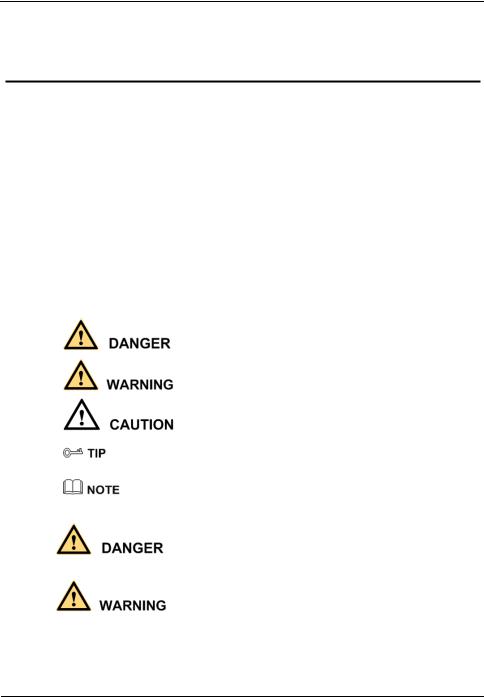
Symbols
This document may contain the following symbols whose meanings are described accordingly.
Symbol |
Description |
|
It alerts you to fatal dangers which, if not avoided, may |
|
cause deaths or severe injuries. |
|
|
|
It alerts you to moderate dangers which, if not avoided, |
|
may cause minor or moderate injuries. |
|
|
|
It alerts you to risks. Neglect of these risks may cause |
|
device damage, data loss, device performance |
|
deterioration, or unpredictable results. |
|
|
|
It provides a tip that may help you resolve problems or |
|
save time. |
|
|
|
It provides additional information. |
|
|
To prevent electric shocks or other dangers, keep power plugs dry and clean.
Strictly observe installation requirements when installing the device. The manufacturer shall not be held responsible for device damage caused by users' nonconformance to these requirements.
Issue V1.0 (2018-06-04) |
i |

|
Digital Video Recorder(DVR) |
Precautions |
User Manual |
Strictly conform to local electrical safety standards and use power adapters that are marked with the LPS standard when installing and using this device. Otherwise, this device may be damaged.
Use accessories delivered with this device. The voltage must meet input voltage requirements for this device.
If this device is installed in places with unsteady voltage, ground this device to discharge high energy such as electrical surges in order to prevent the power supply from burning out.
When this device is in use, ensure that no water or any liquid flows into the device. If water or liquid unexpectedly flows into the device, immediately power off the device and disconnect all cables (such as power cables and network cables) from this device.
Do not focus strong light (such as lighted bulbs or sunlight) on this device. Otherwise, the service life of the image sensor may be shortened.
If this device is installed in places where thunder and lightning frequently occur, ground the device nearby to discharge high energy such as thunder strikes in order to prevent device damage.
Avoid heavy loads, intensive shakes, and soaking to prevent damages during transportation and storage. The warranty does not cover any device damage that is caused during secondary packaging and transportation after the original packaging is taken apart.
Protect this device from fall-down and intensive strikes, keep the device away from magnetic field interference, and do not install the device in places with shaking surfaces or under shocks.
Clean the device with a soft dry cloth. For stubborn dirt, dip the cloth into slight neutral cleanser, gently wipe the dirt with the cloth, and then dry the device.
Do not jam the ventilation opening. Follow the installation instructions provided in this document when installing the device.
Keep the device away from heat sources such as radiators, electric heaters, or other heat equipment.
Keep the device away from moist, dusty, extremely hot or cold places, or places with strong electric radiation.
If the device is installed outdoors, take insectand moisture-proof measures to avoid circuit board corrosion that can affect monitoring.
Remove the power plug if the device is idle for a long time.
Before unpacking, check whether the fragile sticker is damaged. If the fragile sticker is damaged, contact customer services or sales personnel. The manufacturer shall not be held responsible for any artificial damage of the fragile sticker.
ii |
Issue V1.0 (2018-06-04) |

Digital Video Recorder(DVR) |
|
User Manual |
Precautions |
Special Announcement
All complete products sold by the manufacturer are delivered along with nameplates, operation instructions, and accessories after strict inspection. The manufacturer shall not be held responsible for counterfeit products.
This manual may contain misprints, technology information that is not accurate enough, or product function and operation description that is slightly inconsistent with the actual product. The manufacturer will update this manual according to product function enhancement or changes and regularly update the software and hardware described in this manual. Update information will be added to new versions of this manual without prior notice.
This manual is only for reference and does not ensure that the information is totally consistent with the actual product. For consistency, see the actual product.
Issue V1.0 (2018-06-04) |
iii |

|
Digital Video Recorder(DVR) |
Contents |
User Manual |
|
|
Contents |
Precautions.................................................................................................................... |
i |
|
1 Specifications............................................................................................................ |
1 |
|
2 Hard Disk .................................................................................................................. |
3 |
|
2.1 |
Precautions ..................................................................................................................... |
3 |
2.2 |
Hard Disk Recommendation .......................................................................................... |
3 |
2.3 Approximate Video Storage Duration............................................................................. |
3 |
|
2.4 |
Hard Disk Installation .................................................................................................... |
4 |
3 Operation Instruction.............................................................................................. |
8 |
|
3.1 |
Front panel ..................................................................................................................... |
8 |
3.2 |
Rear panel....................................................................................................................... |
8 |
3.3 |
Startup .......................................................................................................................... |
10 |
3.4 |
Powering off the Device ................................................................................................ |
11 |
3.5 |
Logging In to the System .............................................................................................. |
11 |
3.6 |
Changing the Password ................................................................................................ |
12 |
3.7 Adding Cameras ........................................................................................................... |
13 |
|
4 Quick Navigation................................................................................................... |
15 |
|
4.1 |
PTZ Operations ............................................................................................................ |
17 |
|
4.1.1 PTZ .................................................................................................................. |
17 |
|
4.1.2 UTC ................................................................................................................. |
19 |
4.2 |
Playback ....................................................................................................................... |
20 |
4.3 |
Search........................................................................................................................... |
21 |
4.4 |
Picture Grid .................................................................................................................. |
22 |
4.5 |
Event ............................................................................................................................ |
23 |
4.6 Main Menu ................................................................................................................... |
23 |
|
5 Camera Management ............................................................................................ |
25 |
|
5.1 |
Camera Management.................................................................................................... |
26 |
|
5.1.1 Lock a Camera ................................................................................................. |
26 |
|
5.1.2 Unlock a Camera.............................................................................................. |
26 |
5.2 |
Picture Parameter ......................................................................................................... |
27 |
5.3 |
Encode Parameter......................................................................................................... |
28 |
iv |
|
Issue V1.0 (2018-06-04) |

Digital Video Recorder(DVR) |
|
|
User Manual |
Contents |
|
5.4 |
Video loss ..................................................................................................................... |
29 |
5.5 |
Motion Detection.......................................................................................................... |
33 |
5.6 |
Privacy Area ................................................................................................................. |
35 |
5.7 |
Camera tamper ............................................................................................................. |
35 |
5.8 |
OSD settings................................................................................................................. |
36 |
6 System setting......................................................................................................... |
38 |
|
6.1 |
Basic............................................................................................................................. |
38 |
|
6.1.1 System.............................................................................................................. |
39 |
|
6.1.2 Time ................................................................................................................. |
39 |
|
6.1.3 Time zone......................................................................................................... |
40 |
|
6.1.4 DST.................................................................................................................. |
41 |
6.2 |
Network........................................................................................................................ |
42 |
|
6.2.1 Ipv4 .................................................................................................................. |
42 |
|
6.2.2 Port................................................................................................................... |
44 |
|
6.2.3 UPNP ............................................................................................................... |
45 |
|
6.2.4 SMTP ............................................................................................................... |
46 |
|
6.2.5 DDNS............................................................................................................... |
47 |
|
6.2.6 Blacklist ........................................................................................................... |
48 |
6.3 |
Record .......................................................................................................................... |
50 |
6.4 |
Output........................................................................................................................... |
51 |
6.5 Alarm Manager............................................................................................................. |
54 |
|
|
6.5.1 Surveillance...................................................................................................... |
54 |
|
6.5.2 Alarm in ........................................................................................................... |
55 |
6.6 |
Disk .............................................................................................................................. |
56 |
|
6.6.1 Viewing Disk Information................................................................................ |
57 |
|
6.6.2 Clearing Disk Data........................................................................................... |
57 |
6.7 |
Privilege manager......................................................................................................... |
58 |
|
6.7.1 User manager ................................................................................................... |
58 |
|
6.7.2 Modify Password ............................................................................................. |
60 |
6.8 |
Privacy ......................................................................................................................... |
60 |
6.9 Advanced setting .......................................................................................................... |
61 |
|
6.10 App ............................................................................................................................. |
62 |
|
7 Log Center ............................................................................................................... |
64 |
|
8 Alarm........................................................................................................................ |
66 |
|
8.1 |
Event ............................................................................................................................ |
66 |
8.2 |
Timeline ....................................................................................................................... |
67 |
8.3 |
Clear alarm ................................................................................................................... |
68 |
Issue V1.0 (2018-06-04) |
v |

|
Digital Video Recorder(DVR) |
Contents |
User Manual |
9 Web Access.............................................................................................................. |
69 |
9.1 Login ............................................................................................................................ |
69 |
9.2 Live Video .................................................................................................................... |
70 |
9.3 Video Playback............................................................................................................. |
70 |
9.4 Alarm Search ................................................................................................................ |
72 |
9.5 DVR Setting ................................................................................................................. |
74 |
9.5.1 Viewing basic information ............................................................................... |
75 |
9.5.2 Network management ...................................................................................... |
76 |
9.5.2.1 IPv4 ............................................................................................. |
76 |
9.5.2.2 Port .............................................................................................. |
77 |
9.5.2.3 DDNS .......................................................................................... |
78 |
9.5.2.4 SMTP .......................................................................................... |
79 |
9.5.3 Device management ......................................................................................... |
80 |
9.6 Alarm............................................................................................................................ |
82 |
9.7 Storage.......................................................................................................................... |
84 |
9.8 User .............................................................................................................................. |
85 |
9.8.1 Privilege management ...................................................................................... |
85 |
9.8.2 Modify password.............................................................................................. |
88 |
9.8.3 Local ................................................................................................................ |
88 |
10 FAQ ........................................................................................................................ |
90 |
vi |
Issue V1.0 (2018-06-04) |

Digital Video Recorder(DVR) |
|
User Manual |
1 Specifications |
1 Specifications
|
Model |
|
|
0E-HD4C1TB |
|
|
0E-HD8C2TB |
|
|
0E-HD16C2TB |
|
|
|
|
|
|
|
|
|
||||
|
|
|
|
|
|
|
|
|
|
|
|
|
VIDEO |
|
|
|
|
|
|
|
|
|
|
Video Compression |
|
|
H.264 High Profile |
|
|
|
|
|
|
||
|
|
|
|
|
|
|
|
||||
Encode Ability |
|
|
4ch*1080P@15fps |
|
8ch*1080P@15fps |
|
16ch*1080P@15fps |
||||
|
|
|
|
|
|
|
|
||||
Decode Ability |
|
|
4ch *1080P@15fps |
|
8ch*1080P@15fps |
|
16ch*1080P@15fps |
||||
|
|
|
|
|
|
|
|
|
|||
|
|
|
|
Pure Analog: |
|
Pure Analog: |
|
Pure Analog: |
|||
|
|
|
|
4ch*1080P/4ch*720 |
|
8ch*1080P/8ch*720 |
|
16ch*1080P/8ch*72 |
|||
|
|
|
|
P |
|
P |
|
0P |
|||
|
|
|
|
|
|
|
|
|
|
||
|
|
|
|
Mixed Input: |
|
Mixed |
|
Mixed |
|||
|
|
|
|
|
|
|
|
|
|
||
|
|
|
|
4ch*1080P(AHD+T |
|
Input:8ch*1080P(A |
|
Input:16ch*1080P( |
|||
|
|
|
|
|
|
|
|
|
|
||
|
|
|
|
VI+CVI) |
|
HD+TVI+CVI) |
|
AHD+TVI+CVI |
|||
|
|
|
|
|
|
|
|
|
|
||
Video Input |
|
|
4ch*1080P(AHD |
|
8ch*1080P(AHD |
|
16ch*1080P(AHD |
||||
|
|
|
|
|
|
|
|
|
|
||
|
|
|
|
+CVI+ Network |
|
+CVI+ Network |
|
+CVI+ Network) |
|||
|
|
|
|
|
|
|
|
|
|
||
|
|
|
|
4ch*1080P(TVI |
|
8ch*1080P(TVI |
|
16ch*1080P(TVI+C |
|||
|
|
|
|
|
|
|
|
|
|
||
|
|
|
|
+CVI+ Network) |
|
+CVI+ Network) |
|
VI + Network |
|||
|
|
|
|
|
|
|
|
|
|
||
|
|
|
|
Pure Network: |
|
Pure Network: |
|
Pure |
|||
|
|
|
|
|
|
|
|
|
|
||
|
|
|
|
4ch*1080P/4ch*720 |
|
8ch*1080P/8ch*720 |
|
Network:16*1080P/ |
|||
|
|
|
|
P |
|
P |
|
16ch*720P |
|||
|
|
|
|
|
|
|
|
|
|
||
|
AUDIO |
|
|
|
|
|
|
|
|
|
|
Audio Compression |
|
|
G711A |
|
|
|
|
|
|
||
|
|
|
|
|
|
|
|
|
|
||
Two Way Audio |
|
|
Support |
|
|
|
|
|
|
||
|
|
|
|
|
|
|
|
||||
|
RECORD AND PLAYBACK |
|
|
|
|
|
|
||||
|
|
|
|
1 SATA(Each |
|
2 SATA(Each |
|
2 SATA(Each |
|||
Hard Drive |
|
|
maximum support |
|
maximum support |
|
maximum support |
||||
|
|
|
|
6T ) |
|
6T ) |
|
6T ) |
|||
|
|
|
|
|
|
|
|
|
|
||
Record |
|
|
Manual/Event/Timer |
|
|
|
|
|
|
||
|
|
|
|
|
|
|
|
|
|||
Playback |
|
|
4ch(pure local input |
|
8ch(pure local input |
|
16ch(pure local |
||||
|
|
mode) |
|
mode) |
|
input mode) |
|||||
|
|
|
|
|
|
||||||
|
|
|
|
|
|
|
|
||||
|
STORAGE AND BACKUP |
|
|
|
|
|
|
||||
Space Occupation |
|
|
960H:12G~20G/ day*channel |
|
|
|
|||||
|
|
|
|
|
|
|
|
|
|
||
|
|
720P:10G~20G/ day*channel |
|
|
|
||||||
|
|
|
|
|
|
|
|||||
|
|
|
|
|
|
|
|
|
|
|
|
Issue V1.0 (2018-06-04) |
1 |

|
|
|
|
|
|
|
|
|
Digital Video Recorder(DVR) |
||||
1 Specifications |
|
|
|
|
|
|
|
User Manual |
|||||
|
|
|
|
|
|
|
|
|
|
|
|
|
|
|
|
Model |
|
|
0E-HD4C1TB |
|
|
0E-HD8C2TB |
|
|
0E-HD16C2TB |
|
|
|
|
|
|
|
|
|
|
|
|
|
|
|
|
|
|
|
|
|
1080P: 20G~30G/ day*channel |
|
|
|
|
|
|||
|
|
|
|
|
|
|
|
|
|
|
|||
|
|
|
|
|
Audio:691.2M/ day*channel |
|
|
|
|
|
|||
|
|
|
|
|
|
|
|
|
|
|
|||
|
Backup Mode |
|
USB HDD |
|
|
|
|
|
|
|
|||
|
|
|
|
|
|
|
|
|
|
|
|
||
|
|
INTERFACE |
|
|
|
|
|
|
|
|
|
|
|
|
|
|
|
|
4ch BNC |
|
8ch BNC |
|
|
16ch BNC |
|
||
|
Video Input |
AHD/TVI/CVI/C |
AHD/TVI/CVI/C |
AHD/TVI/CVI/C |
|
||||||||
|
|
|
|
|
VBS |
|
VBS |
|
|
VBS |
|
||
|
|
|
|
|
|
|
|
|
|
||||
|
Video Output |
|
1ch VGA,1ch HDMI,1ch CVBS |
|
|
|
|
|
|||||
|
|
|
|
|
|
|
|
|
|
||||
|
Audio Input |
|
4ch RCA |
|
8ch RCA |
|
|
6ch RCA |
|
||||
|
|
|
|
|
|
|
|
|
|
|
|||
|
Audio Output |
|
1ch RCA |
|
|
|
|
|
|
|
|||
|
|
|
|
|
|
|
|
|
|
|
|||
|
Alarm Input |
|
N/A |
|
4ch |
|
|
|
|
|
|||
|
|
|
|
|
|
|
|
|
|
|
|||
|
Alarm Output |
|
N/A |
|
1ch |
|
|
|
|
|
|||
|
|
|
|
|
|
|
|
|
|
||||
|
Network Interface |
|
1 RJ45 10M/100M Adaptive Ethernet Port |
|
|
|
|
|
|||||
|
|
|
|
|
|
|
|
|
|||||
|
PTZ Control |
|
RS485, Support Multiple PTZ Protocols |
|
|
|
|
|
|||||
|
|
|
|
|
|
|
|
|
|
|
|||
|
USB |
|
2 USB |
|
|
|
|
|
|
|
|||
|
|
|
|
|
|
|
|
|
|
|
|||
|
Hard Disk |
|
1 SATA |
|
2 SATA |
|
|
|
|
|
|||
|
|
|
|
|
|
|
|
|
|
|
|
||
|
|
GENERAL |
|
|
|
|
|
|
|
|
|
|
|
|
Power |
|
DC12V/2A |
|
DC12V/4A |
|
|
|
|
|
|||
|
|
|
|
|
|
|
|
|
|
|
|
||
|
Operating |
|
-10°C ~ 50°C (14°F ~ 122°F ) |
|
|
|
|
|
|||||
|
Temperature |
|
|
|
|
|
|
||||||
|
|
|
|
|
|
|
|
|
|
|
|||
|
|
|
|
|
|
|
|
|
|
|
|
|
|
|
Dimension |
|
255mm(L)*255mm( |
|
350mm(L)* 295mm(W)*45mm(H) |
|
|||||||
|
|
W)*45mm(H) |
|
|
|||||||||
|
|
|
|
|
|
|
|
|
|
|
|
||
|
|
|
|
|
|
|
|
|
|
|
|||
|
Product Weight |
|
900g |
|
1900g |
|
|
|
|
|
|||
|
|
|
|
|
|
|
|
|
|
|
|
|
|
2 |
Issue V1.0 (2018-06-04) |
Digital Video Recorder(DVR) |
|
User Manual |
2 Hard Disk |
2 Hard Disk
2.1Precautions
Formatting will clear all video data on the hard disk. Use this function only when necessary.
Be sure to uninstall the hard disk before removing it from the DVR during runtime; otherwise, the hard disk may be damaged or data may be lost.
The DVR must be connected to a stable power supply during runtime; otherwise, the hard disk may be damaged or data may be lost.
The maximum capacity of a single hard disk cannot exceed 6 TB.
2.2Hard Disk Recommendation
Seagate or Western Digital hard disks which are highly stable and inexpensive are recommended.
2.3 Approximate Video Storage Duration
Table 2-1 Approximate Video storage duration
Maximum Hard Disk |
Maximum Bit Rate |
Approximate Video |
Capacity |
|
Storage Duration |
1 ×6 TB |
18 Mbps |
28 days |
|
|
|
2×6 TB |
36 Mbps |
28 days |
|
|
|
4 ×6 TB |
72 Mbps |
28 days |
|
|
|
Formulae for calculating the approximate video storage duration:
Step 1 Use the following formula to calculate the storage capacity q (unit: MBybte) required to record a single video per hour:
q = d/8×3600/1024
Issue V1.0 (2018-06-04) |
3 |

|
Digital Video Recorder(DVR) |
2 Hard Disk |
User Manual |
d indicates the bit rate (unit: Kbit/s).
Step 2 Use the following formula to calculate the approximate video storage duration t (unit: day)
w indicates the capacity (unit: Mbyte) of a single hard disk. n indicates the number of disks.
h indicates the recording duration per day.
c indicates the number of video inputs of the DVR.
Table 2-2 shows examples of approximate video storage duration (h is 24 hours). Table 2-2 Examples of approximate video storage duration
Hard Disk |
Bit Rate |
Video Count |
|
Approximate Video |
Capacity |
|
|
|
Storage Duration |
1×6TB |
D1, 1.5Mbps |
4 |
|
85 days |
|
|
|
|
|
1×6TB |
720p, 3Mbps |
4 |
|
47 days |
|
|
|
|
|
1×6TB |
1080p, 4.5Mbps |
4 |
|
28 days |
|
|
|
|
|
2×6TB |
D1, 1.5Mbps |
8 |
|
85 days |
|
|
|
|
|
2×6TB |
720p, 3Mbps |
8 |
|
47 days |
|
|
|
|
|
2×6TB |
1080p, 4.5Mbps |
8 |
|
28 days |
|
|
|
|
|
4×6TB |
D1, 1.5Mbps |
16 |
|
85 days |
|
|
|
|
|
4×6TB |
720p, 3Mbps |
16 |
|
47 days |
|
|
|
|
|
4×6TB |
1080p, 4.5Mbps |
16 |
|
28 days |
|
|
|
|
|
The data listed in the preceding table is only for your reference. The recording time estimate may be different from the actual recording time. The user shall be liable for any loss incurred as a result thereof.
2.4 Hard Disk Installation
Take the following steps to install a hard disk:
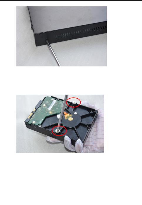
Step 1 Unscrew the four fixing screws on both sides and one fixing screw on the back, then remove the upper cover, as shown in Figure 2-1.
4 |
Issue V1.0 (2018-06-04) |
Digital Video Recorder(DVR) |
|
User Manual |
2 Hard Disk |
Figure 2-1 Removing the upper cover
Step 2 Take out the hard disk fixing screws and silicone cushion included in the accessory package, route the fixing screw through the silicone cushion, and install it to the screw holes, as shown in Figure 2-2.
Figure 2-2 Installing the hard disk fixing screw
Step 3 Route the hard disk fixing screws through the holes on the base, push the hard disk to the appropriate position according to the direction of arrow, as shown in Figure 2-3.
Issue V1.0 (2018-06-04) |
5 |
|
Digital Video Recorder(DVR) |
2 Hard Disk |
User Manual |
Figure 2-3 Inserting the hard disk
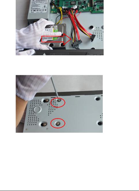
Step 4 Turn the device over, and fasten two hard disk fixing screws, as shown in Figure 2-4.
Figure 2-4 Fixing the hard disk
Step 5 Install the other hard disk according to Step 2, Step 3, and Step 4, then insert the hard disk data cable and power cable, as shown in Figure 2-5.
6 |
Issue V1.0 (2018-06-04) |

Digital Video Recorder(DVR) |
|
User Manual |
2 Hard Disk |
Figure 2-5 Inserting the cable
Step 6 Put on the upper cover, and fasten the fixing screws, as shown in Figure 2-6. Figure 2-6 Put on the upper cover
----End
Issue V1.0 (2018-06-04) |
7 |
|
Digital Video Recorder(DVR) |
3 Operation Instruction |
User Manual |
3 Operation Instruction
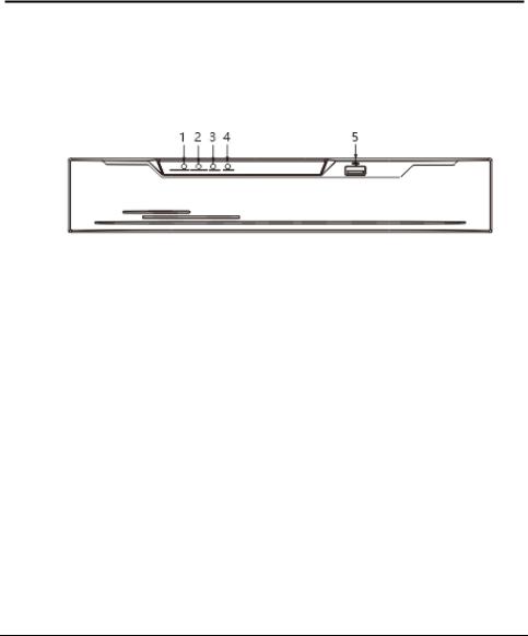
3.1 Front panel
Figure 3-1 shows the front panel of DVR. Table 3-1 shows the description of front panel.
Figure 3-1 Front panel
Table 3-1 Elements of the front panel
NO. |
|
|
Element |
|
|
Description |
|
|
|
|
|
|
|
Power indicator, When DVR is operating, the |
|
1 |
|
|
POWER |
|
|
Power indicator is steady on. When DVR is |
|
|
|
|
|
|
|
shut down, the PWR indicator is turned off. |
|
|
|
|
|
|
|
|
|
2 |
|
|
ALARM |
|
|
Alarm indicator |
|
|
|
|
|
This indicator flashes when alarm is transmitted |
|
||
|
|
|
|
|
|
|
|
|
|
|
|
|
|
|
|
3 |
|
|
REC |
|
|
Record indicator |
|
|
|
|
|
This indicator flashes when DVR is recording |
|
||
|
|
|
|
|
|
|
|
|
|
|
|
|
|
|
|
4 |
|
|
NET |
|
|
Net indicator |
|
|
|
|
|
This indicator flashes when DVR record |
|
||
|
|
|
|
|
|
|
|
|
|
|
|
|
|
|
|
5 |
|
|
USB |
|
|
Supports connection to a USB mouse, a USB |
|
|
|
|
|
flash drive or USB removable hard disk. |
|
||
|
|
|
|
|
|
|
|
|
|
|
|
|
|
|
|
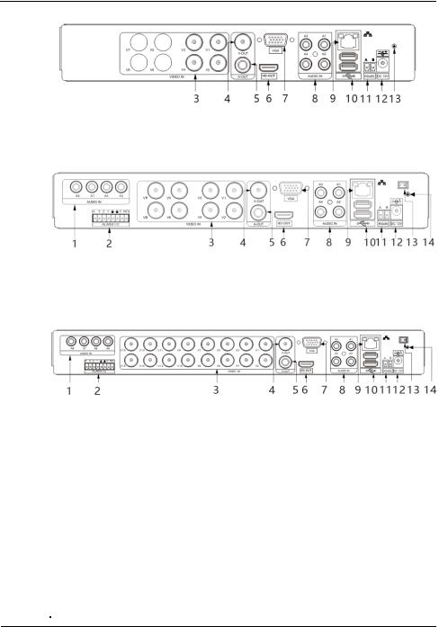
3.2 Rear panel
Figure 3-2 shows the rear panel of 0E-HD4C1TB and the interfaces on it.
8 |
Issue V1.0 (2018-06-04) |
Digital Video Recorder(DVR) |
|
User Manual |
3 Operation Instruction |
Figure 3-2 Rear panel of 0E-HD4C1TB
Figure 3-3 shows the rear panel of 0E-HD8C2TB and the interfaces on it. Figure 3-3 Rear panel of 0E-HD8C2TB
Figure 3-3 shows the rear panel of 0E-HD16C2TB and the interfaces on it. Figure 3-4 Rear panel of 0E-HD16C2TB
Table 3-2 shows the description of rear panel
Table 3-2 Elements of the real panel
NO. |
|
|
Name |
|
|
Description |
|
1 |
|
|
AUDIO IN |
|
|
Audio Input |
|
|
|
|
|
|
|
|
|
2 |
|
|
ALARM I/O |
|
|
Alarm Input/Output |
|
|
|
|
|
|
|
|
|
3 |
|
|
VIDEO IN |
|
|
Video input |
|
|
|
|
|
|
|
|
|
4 |
|
|
CVBS |
|
|
CVBS output interface |
|
|
|
|
|
|
|
|
|
5 |
|
|
A-OUT |
|
|
Audio output |
|
|
|
|
|
|
|
|
|
6 |
|
|
HD-OUT |
|
|
Video output interface |
|
|
|
|
|
|
|
|
|
7 |
|
|
VGA |
|
|
|
|
|
|
|
|
|
|
||
|
|
|
|
|
|
|
|
8 |
|
|
AUDIO IN |
|
|
Audio Input |
|
Issue V1.0 (2018-06-04) |
9 |

|
|
|
|
|
|
|
Digital Video Recorder(DVR) |
|
3 Operation Instruction |
|
|
|
User Manual |
||||
|
|
|
|
|
|
|
|
|
|
NO. |
|
|
Name |
|
|
Description |
|
|
9 |
|
|
LAN network |
|
|
RJ45 10 /100/1000 Mbps adaptive |
|
|
|
|
interface |
|
|
Ethernet interface |
|
|
|
|
|
|
|
|
|
||
|
|
|
|
|
|
|
|
|
|
10 |
|
|
USB |
|
|
Supports connection to a USB mouse, a USB |
|
|
|
|
|
|
flash drive or USB removable hard disk. |
|
||
|
|
|
|
|
|
|
|
|
|
|
|
|
|
|
|
|
|
|
11 |
|
|
RS485 |
|
|
RS485 port |
|
|
|
|
|
|
|
|
|
|
|
12 |
|
|
DC power |
|
|
Connected to an external power adapter |
|
|
|
|
interface |
|
|
|
||
|
|
|
|
|
|
|
|
|
|
|
|
|
|
|
|
|
|
|
13 |
|
|
Power switch |
|
|
-(Optional for different DVR) |
|
|
|
|
|
|
|
|
|
|
|
14 |
|
|
Ground screw |
|
|
Safe ground screw of the device |
|
|
|
|
|
|
|
|
|
|
3.3 Startup
Before starting the DVR, ensure that the DVR is connected to a power supply.
When the DVR is connected to a power supply, it starts automatically upon the initial power-on.
Ensure that a power supply is connected to the DVR correctly.
Before starting the DVR, ensure that a monitor is connected to the HD-OUT or VGA interface of the DVR correctly.
The DVR may not operate normally when a power supply exception occurs, likely causing damage to the DVR in serious conditions. In such a circumstance, you are advised to use a regulated power supply.
After the DVR is connected to a power supply, the power indicator is steadily on. Start the DVR. The real-time video screen is displayed, as shown in Figure 3-5.
10 |
Issue V1.0 (2018-06-04) |

Digital Video Recorder(DVR) |
|
User Manual |
3 Operation Instruction |
Figure 3-5 Real-time video screen
Users need to provide a hard disk for the DVR. The hard disk is strictly detected during device startup. If the detection result failed, the possible causes are as follows:
The hard disk is new and is not formatted. Log in to the system and format the hard disk.
The hard disk is formatted, but the file system is inconsistent with the file system supported by the DVR. Format the hard disk.
The hard disk is damaged.
3.4Powering off the Device
Click the main menu and choose System setting > Advanced setting, the advanced setting page is displayed, click shutdown to power off the DVR. If there is a power switch on the rear panel of the DVR, you can turn off the power switch to disconnect the DVR from the power supply.
3.5 Logging In to the System
Logging In to the Device
Step 1 On the DVR login page, select the language, as shown in Figure 3-6.
Issue V1.0 (2018-06-04) |
11 |

|
Digital Video Recorder(DVR) |
3 Operation Instruction |
User Manual |
Figure 3-6 Login page
Step 2 Enter the username and password.
The username and password are both admin.
If you forget password, click Forgot password. You can choose a way to find previous password:
1.Scan the QR code and send the QR code to your seller.
2.Click Send Password to you E-mail. A password retrieval email will be sent to your email address (for details, see 6.2.4 Step 6). Then, you can retrieve password by following operations described in the email.
Step 3 Click Login to access the main User Interface (UI).
----End
3.6 Changing the Password
Description
The change default password page will be displayed as shown in Figure 3-7, when you login the system for the first time.
12 |
Issue V1.0 (2018-06-04) |
Digital Video Recorder(DVR) |
|
User Manual |
3 Operation Instruction |
Figure 3-7 Change the default password page
Operation Steps
Step 1 Enter the new password, and confirmation password.
Step 2 Click OK.
The real-time video screen is displayed
3.7 Adding Cameras
This DVR can be connected to both analog cameras and network cameras. The DVR gives preference to the access of the analog camera by default.
The DVR can be directly connected to analog cameras through bayonet nut connector (BNC) cables.
Figure 3-8 shows the topology of the DVR.
Issue V1.0 (2018-06-04) |
13 |

|
Digital Video Recorder(DVR) |
3 Operation Instruction |
User Manual |
Figure 3-8 DVR topology
Switch
Remote monitor
----End
14 |
Issue V1.0 (2018-06-04) |
|
Digital Video Recorder(DVR) |
Quick Navigation |
User Manual |
4 Quick Navigation
After the DVR operation screen is displayed, move the cursor to the downmost position of the DVR screen. The DVR floating menu bar is displayed.
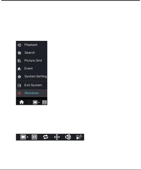
Click  in the left of DVR floating menu bar. a quick main menu is displayed. The quick main menu provides Playback, Search, Picture Grid, Event, System Setting, Exit System and Shutdown, as shown in Figure 4-1.
Figure 4-1 Quick main menu
In the middle of DVR floating menu bar, the video tool bar provides video window switching, Dwell on, pan-tilt-zoom (PTZ) control, audio, and video signal, as shown in Figure 4-2.
Figure 4-2 Real-time video toolbar
The real-time video toolbar is described as follows:
Issue V1.0 (2018-06-04) |
15 |
Digital Video Recorder(DVR) |
|
User Manual |
Quick Navigation |
 : layout button. After this button is clicked, the real-time video window is
switched between the single-screen mode and multi-screen mode. Click  on the right of screen splitting format and choose the channels to view the video.
 : Dwell on, After this button is clicked, the layout dwell on screen is enable, for how to set the dwell on, please see 6.4 Step 2.
 : PTZ button. After this button is clicked, the PTZ operation screen is displayed, where you can adjust the PTZ to control cameras.
 : Audio button. After this button is clicked, the audio setting screen is displayed, where you can choose the channel and adjust the volume.
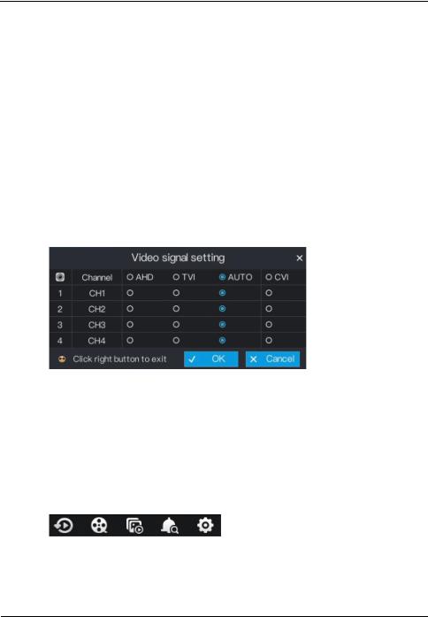
 : Video signal button. After this button is clicked, the video signal setting screen is displayed, as show in Figure 4-3.
Figure 4-3 Video signal setting
Normally, DVR video signal setting is auto by default, the DVR obtains the video signal of analog camera automatically.
When the video is displayed incorrectly, choose the same video signal according to the video signal of analog camera and click OK to save the signal setting.
A main menu quick toolbar is display on the right of DVR floating menu bar. The main menu quick toolbar provides Playback, Search, Picture grid, Event, System setting, as shown in Figure 4-4.
Figure 4-4 Main menu quick toolbar
16 |
Issue V1.0 (2018-06-04) |

|
Digital Video Recorder(DVR) |
Quick Navigation |
User Manual |
4.1 PTZ Operations
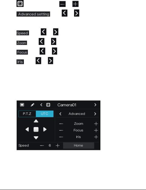
Click the PTZ button on the real-time video toolbar. The PTZ control page is displayed, as shown in Figure 4-5.
Figure 4-5 PTZ control
4.1.1 PTZ
The PTZ control and function settings are applicable only to high-speed dome, PTZ cameras and cameras externally connected to PTZs,
The function in the PTZ control screen is described as follows:
 : layout button. After this button is clicked, the real-time video window is switched.
 : PTZ setting button. After this button is clicked, the PTZ setting page is displayed, as shown in Figure 4-6.
Figure 4-6 PTZ setting
|
|
|
|
|
|
Issue V1.0 (2018-06-04) |
17 |
|
Digital Video Recorder(DVR) |
|
User Manual |
Quick Navigation |
Operation Steps
Step 2 Select a P.T.Z control type from the drop-down list box.
RS485: Use RS485 protocol to control analog high-speed domes and analog cameras with Motorized zoom lenses.
Coaxial: Use coaxial protocol to control analog high-speed domes and analog cameras with Motorized zoom lenses.
All: Math the RS485 or coaxial protocol automatically to control analog high-speed domes and analog cameras with Motorized zoom lenses.
Step 3 Select a type of protocol from the drop-down list box. Step 4 Set an address.
Step 5 Select a baud rate from the drop-down list box.
Step 6 Click OK to save P.T.Z setting or click cancel to cancel the P.T.Z setting.
Preset
You can configure preset positions and quickly rotate the camera to a preset position by invoking the preset position.
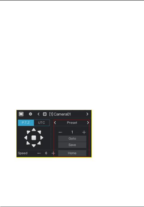
Click  or
or  of Advanced setting, the preset setting page is displayed, as the red frame shown in Figure 4-7.
Figure 4-7 . PTZ setting
Operation Steps
Step 1 Set preset.
1.Click  or
or  to set the preset ID.
2.Click direction button to rotate the camera to a position and click Save to save the preset.
Step 2 Invoke preset.
18 |
Issue V1.0 (2018-06-04) |
|
Digital Video Recorder(DVR) |
Quick Navigation |
User Manual |
1.Select the preset ID.
2.Click Goto to invoke preset, the camera rotate the preset position. Or click Home to rotate the camera to the first preset position.
: Channel button. Click |
or |
to select the P.T.Z control channel. |
: Click |
or |
to enter the preset setting page. |
 : direction button. Click this button to rotate the position of camera..
: Click |
or |
to set the camera speed. |
: Click |
or |
to zoom the lens in or out. |
: Click |
or |
to adjust the focal length. |
: Click |
or |
to adjust the aperture. |
4.1.2 UTC
The UTC control and function settings are applicable to front-end HD camera and OSD operation of front-end HD camera.
Click UTC in PTZ control page, the UTC screen is displayed, as shown in Figure 4-8.
Figure 4-8 UTC screen
For HD camera of Motorized lens, click  or
or  of zoom, focus and iris to adjust the view angle and focal length.
For details of OSD operation, see Camera OSD Operation Guide.
Issue V1.0 (2018-06-04) |
19 |

Digital Video Recorder(DVR) |
|
User Manual |
Quick Navigation |
4.2 Playback
Playback refers to playing back a video.
Click Playback in the quick navigation bar to access the playback screen, as shown in Figure 4-9.
Figure 4-9 Playback screen
The toolbar at the bottom of the playback screen is described as follows:  : Slow play
 : Fast forward
 : Pause
 : Backup. After this button is clicked, the video backup starts. This function is available after a USB flash drive is connected to the DVR.
 : Download. After this button is clicked, the backup ends. This function is available after the backup function is enabled.
 : Magnify. Apply only to a single screen. After this button is clicked, the image magnified to 150%, click this button again to restore the original size.
20 |
Issue V1.0 (2018-06-04) |
|
Digital Video Recorder(DVR) |
Quick Navigation |
User Manual |
 : Full screen off. After this button is clicked, the device returns to the real-time video screen.
 : Indicates whether to insert a USB flash drive.
  indicates that a USB flash
drive is inserted into the DVR.  indicates that no USB flash drive is inserted into the DVR.
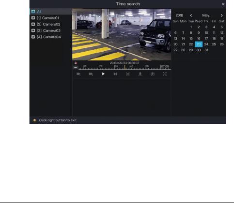
4.3 Search
Search refers to searching for a video by date and time.
Operation Description
Click Search in the quick navigation bar to access the search screen, as shown in Figure 4-10.
Figure 4-10 Search screen
The toolbar at the bottom of the play window is described as follows:  : Slow play
 : Fast forward
  : Pause
Issue V1.0 (2018-06-04) |
21 |

Digital Video Recorder(DVR) |
|
User Manual |
Quick Navigation |
 : Backup. After this button is clicked, the video backup starts. This function is available after a USB flash drive is connected to the DVR.
 : Download. After this button is clicked, the backup ends. This function is available after the backup function is enabled.
 : Intelligent motion detection. After this button is clicked, the device automatically locates a moving target.
 : Full screen. After this button is clicked, the device plays a video in full screen.
Operation Steps
Step 1 Click a camera in the camera list on the left side of the search screen. The video view of the selected camera is displayed in the play window.
Step 2 Select a date in the calendar on the right side of the search screen.
Click  or
or  on the left side of the time axis below the play window to switch the time axis, and then select time. Then, the play window plays the video in the specified time range.
 : Videos are searched on an hourly basis.
 : Videos are searched on 24 hourly basis.
----End
4.4 Picture Grid
Picture grid refers to evenly dividing the video of a channel by time range and searching for a video based on thumbnails divided by time range.
Click Picture Grid on the quick navigation bar to access the picture grid screen, as shown in Figure 4-11.
22 |
Issue V1.0 (2018-06-04) |
 Loading...