


W box technologies 0E-13BF36, 0E-40D28WDR, 0E-13D28, 0E-21D28WDR, 0E-40BF36WDR User Manual
...0E-13D28
0E-13BF36
0E-21D28WDR
0E-21BF36WDR
0E-40D28WDR
0E-40BF36WDR
High-Resolution IR Camera
User Manual
If you have any questions, please call W Box Tech Support 1-833-574-9124 for assistance.
E-mail tech@wboxsupport.com

High-Resolution IR Camera |
|
User Manual |
Hardware Connection |
Precautions
Precautions
Fully understand this document before using this device, and strictly observe rules in this document when using this device. If you install this device in public places, provide the tip "You have entered the area of electronic surveillance" in an eyecatching place. Failure to correctly use electrical products may cause fire and severe injuries. To prevent accidents, carefully read the following context:
Symbols
This document may contain the following symbols whose meanings are described accordingly.
Symbol |
Description |
|
It alerts you to fatal dangers which, if not avoided, may |
|
cause deaths or severe injuries. |
|
|
|
It alerts you to moderate dangers which, if not avoided, |
|
may cause minor or moderate injuries. |
|
|
|
It alerts you to risks. Neglect of these risks may cause |
|
device damage, data loss, device performance |
|
deterioration, or unpredictable results. |
|
|
|
It provides a tip that may help you resolve problems or |
|
save time. |
|
|
|
It provides additional information. |
|
|
To prevent electric shocks or other dangers, keep power plugs dry and clean.
Strictly observe installation requirements when installing the device. The manufacturer shall not be held responsible for device damage caused by users' nonconformance to these requirements.
Issue V1.0 (2018-05-11) |
i |

|
High-Resolution IR Camera |
Hardware Connection |
User Manual |
Strictly conform to local electrical safety standards and use power adapters that are marked with the LPS standard when installing and using this device. Otherwise, this device may be damaged.
Use accessories delivered with this device. The voltage must meet input voltage requirements for this device.
If this device is installed in places with unsteady voltage, ground this device to discharge high energy such as electrical surges in order to prevent the power supply from burning out.
When this device is in use, ensure that no water or any liquid flows into the device. If water or liquid unexpectedly flows into the device, immediately power off the device and disconnect all cables (such as power cables and network cables) from this device.
Do not focus strong light (such as lighted bulbs or sunlight) on this device. Otherwise, the service life of the image sensor may be shortened.
If this device is installed in places where thunder and lightning frequently occur, ground the device nearby to discharge high energy such as thunder strikes in order to prevent device damage.
Avoid heavy loads, intensive shakes, and soaking to prevent damages during transportation and storage. The warranty does not cover any device damage that is caused during secondary packaging and transportation after the original packaging is taken apart.
Protect this device from fall-down and intensive strikes, keep the device away from magnetic field interference, and do not install the device in places with shaking surfaces or under shocks.
Clean the device with a soft dry cloth. For stubborn dirt, dip the cloth into slight neutral cleanser, gently wipe the dirt with the cloth, and then dry the device.
Do not jam the ventilation opening. Follow the installation instructions provided in this document when installing the device.
Keep the device away from heat sources such as radiators, electric heaters, or other heat equipment.
Keep the device away from moist, dusty, extremely hot or cold places, or places with strong electric radiation.
If the device is installed outdoors, take insectand moisture-proof measures to avoid circuit board corrosion that can affect monitoring.
Remove the power plug if the device is idle for a long time.
Before unpacking, check whether the fragile sticker is damaged. If the fragile sticker is damaged, contact customer services or sales personnel. The manufacturer shall not be held responsible for any artificial damage of the fragile sticker.
ii |
Issue V1.0 (2018-05-11) |

High-Resolution IR Camera |
|
User Manual |
Hardware Connection |
Special Announcement
All complete products sold by the manufacturer are delivered along with nameplates, operation instructions, and accessories after strict inspection. The manufacturer shall not be held responsible for counterfeit products.
This manual may contain misprints, technology information that is not accurate enough, or product function and operation description that is slightly inconsistent with the actual product. The manufacturer will update this manual according to product function enhancement or changes and regularly update the software and hardware described in this manual. Update information will be added to new versions of this manual without prior notice.
This manual is only for reference and does not ensure that the information is totally consistent with the actual product. For consistency, see the actual product.
Issue V1.0 (2018-05-11) |
iii |

|
High-Resolution IR Camera |
Hardware Connection |
User Manual |
|
Contents |
|
1 Hardware Connection ............................................................................................. |
6 |
|
2 Eyeball Camera......................................................................................................... |
7 |
|
2.1 |
Dimensions..................................................................................................................... |
7 |
2.2 |
Device Installation.......................................................................................................... |
7 |
3 Bullet camera .......................................................................................................... |
11 |
|
3.1 |
Dimensions.................................................................................................................... |
11 |
3.2 |
Device Installation........................................................................................................ |
12 |
4 Web Operation ....................................................................................................... |
15 |
|
4.1 |
Quick start .................................................................................................................... |
15 |
|
4.1.1 Login and Logout............................................................................................. |
15 |
|
4.1.2 Changing the Password .................................................................................... |
16 |
|
4.1.3 Main Page Layout ............................................................................................ |
17 |
4.2 |
Browsing Real-Time Videos......................................................................................... |
19 |
4.3 |
Configuring the Device ................................................................................................ |
21 |
|
4.3.1 Configuring the Device Information ................................................................ |
21 |
4.4 Setting Video and Audio Stream Parameters ................................................................ |
23 |
|
|
4.4.2 Setting SVC Stream Parameters ....................................................................... |
27 |
|
4.4.3 Region of Interest............................................................................................. |
28 |
|
4.4.4 Setting Local Network Parameters ................................................................... |
30 |
|
4.4.5 Configuring Device Ports................................................................................. |
33 |
|
4.4.6 Configuring the Date and Time ........................................................................ |
34 |
|
4.4.7 Setting the Channel Name, Video System, and Source Resolution .................. |
37 |
|
4.4.8 Setting OSD Parameters................................................................................... |
38 |
|
4.4.9 System Service ................................................................................................. |
41 |
4.5 |
Configuring the Alarm Function................................................................................... |
42 |
|
4.5.1 Setting Disk Alarm Parameters ........................................................................ |
42 |
|
4.5.2 Setting Network Alarm Parameters .................................................................. |
42 |
|
4.5.3 Setting Motion Alarm Parameters .................................................................... |
43 |
|
4.5.4 Setting push message Parameters ..................................................................... |
45 |
4.6 |
Configuring the Recording Function ............................................................................ |
46 |
|
4.6.1 Configuring a Recording Policy....................................................................... |
46 |
iv |
Issue V1.0 (2018-05-11) |

High-Resolution IR Camera |
|
User Manual |
Hardware Connection |
4.6.2 Configuring a Recording Directory.................................................................. |
48 |
4.6.3 Configuring the SD Card or NAS Recording ................................................... |
50 |
4.7 Configuring the Privacy Mask Function....................................................................... |
51 |
4.8 Configuring the Network Service................................................................................. |
53 |
4.8.1 Setting 802.1x Parameters................................................................................ |
53 |
4.8.2 Setting DDNS Parameters ................................................................................ |
54 |
4.8.3 Setting PPPoE Parameters................................................................................ |
55 |
4.8.4 Setting Port Mapping Parameters ..................................................................... |
56 |
4.8.5 Setting SMTP Parameters ................................................................................ |
58 |
4.8.6 Setting FTP Parameters .................................................................................... |
60 |
4.8.7 Setting IP Filter Parameters.............................................................................. |
62 |
4.8.8 Setting CGI Alarm Service Center Parameters................................................. |
65 |
4.8.9 Setting SNMP Parameters ................................................................................ |
68 |
4.9 Privilege Manager ........................................................................................................ |
71 |
4.10 Configuring Protocol Parameters ............................................................................... |
75 |
4.10.1 Checking Protocol Information ...................................................................... |
75 |
4.10.2 Setting Security Authentication...................................................................... |
75 |
4.10.3 Setting Multicast Parameters.......................................................................... |
76 |
4.11 Querying Operation Logs ........................................................................................... |
78 |
4.11.2 Querying Operation Logs ............................................................................... |
78 |
4.11.3 Querying Alarm Logs ..................................................................................... |
79 |
4.11.4 Reporting Logs............................................................................................... |
81 |
4.12 Maintaining the Device .............................................................................................. |
81 |
4.12.1 Restarting a Device ........................................................................................ |
81 |
4.12.2 Updating the software package ...................................................................... |
82 |
4.12.3 Restoring a Device to Factory Settings .......................................................... |
83 |
4.13 Local Configuration ................................................................................................... |
83 |
5 Technical Specifications ....................................................................................... |
85 |
Issue V1.0 (2018-05-11) |
v |

|
High-Resolution IR Camera |
Hardware Connection |
User Manual |
1 Hardware Connection
Figure 1-1 shows the power and network cables.
Figure 1-1 Power and network cables
Table 1-1 shows the description of the cable.
Table 1-1 description of the cable
ID |
Core |
Description |
|
|
|
1 |
Network access port |
Connects to a standard Ethernet cable. |
|
|
|
2 |
Power supply (DC 12V) |
Connects to a 12V(-15%-+10% ) direct current |
|
|
(DC) power supply. |
|
|
|
6 |
Issue V1.0 (2018-05-11) |

High-Resolution IR Camera |
|
User Manual |
Eyeball Camera |
2 Eyeball Camera
2.1 Dimensions
Figure 2-1 shows the camera dimensions of 0E-13D28 and 0E-21D28WDR. Figure 2-1 Dimensions of 0E-13D28 and 0E-21D28WDR (unit: mm)
Figure 2-2 shows the camera dimensions of 0E-40D28WDR.
Figure 2-2 Dimensions of 0E-40D28WDR (unit: mm)
2.2 Device Installation
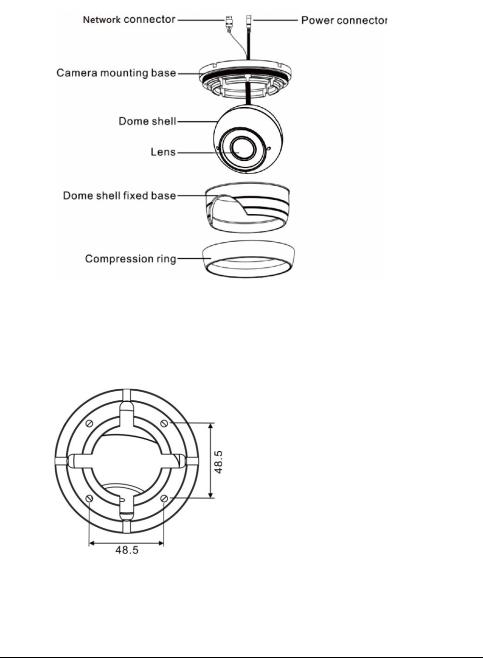
Step 1 Open a package, take out the camera, unscrew the camera compression ring, and disassemble the camera, the camera components is shown in Figure 2-3.
Issue V1.0 (2018-05-11) |
7 |
|
High-Resolution IR Camera |
Eyeball Camera |
User Manual |
Figure 2-3 Camera components
Step 2 Use the base as drill template, drill holes on the ceiling or wall, and reserve the cable entries of the video/power cables.
Figure 2-4 and Figure 2-5 shows the dimensions of the camera mounting base.
Figure 2-4 Dimensions of the 0E-HDD1MP28 and 0E-HDD2MP28 mounting base
8 |
Issue V1.0 (2018-05-11) |
High-Resolution IR Camera |
|
User Manual |
Eyeball Camera |
Figure 2-5 Dimensions of the 0E-HDDMO2812 mounting base
Step 3 Nail swell plastic buttons in to drilled holes, and fix the camera mounting base to the ceiling (or wall) by use of self-tapping screws.
Step 4 Install the compression ring, the dome shell, and the dome shell fixed base on the camera mounting base.
Figure 2-6 shows camera installation.
Figure 2-6 Camera installation
Step 5 Turn the main body, adjust the lens direction, and note the position of the dome cover window.
Issue V1.0 (2018-05-11) |
9 |
|
High-Resolution IR Camera |
Eyeball Camera |
User Manual |
Connect the BNC connector of the power or video cable to a video signal cable and connect the other connector to a low-voltage power cable. After installing the camera, directly connect the video cable and power cable.
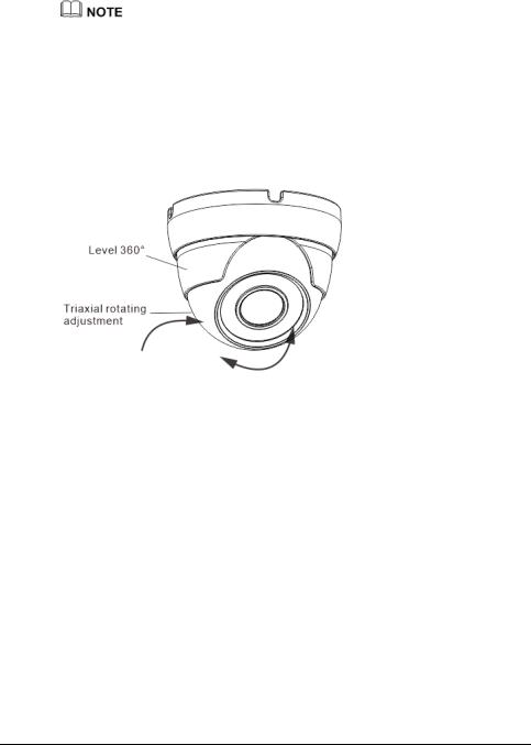
Adjust the position of the camera by triaxial rotation: rotating horizontally, rotating up and down, and performing lens axial rotation, and adjust the camera direction and lens alignment target.
Figure 2-7 shows monitoring direction adjustment.
Figure 2-7 Monitoring direction adjustment
Step 6 Use soft cloth to wipe the lens front glass which is likely to be soiled due to installation for cleaning the camera, and complete product installation and debugging.
----End
10 |
Issue V1.0 (2018-05-11) |

High-Resolution IR Camera |
|
User Manual |
Bullet camera |
3 Bullet camera
3.1 Dimensions
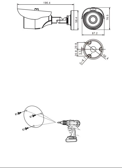
Figure 3-1 shows the dimensions of 0E-40BF36WDR.
Figure 3-1 dimensions of 0E-40BF36WDR
Figure 3-2 shows the dimensions of 0E-13BF36 and 0E-21BF36WDR.
Issue V1.0 (2018-05-11) |
11 |
|
High-Resolution IR Camera |
Bullet camera |
User Manual |
Figure 3-2 dimensions of 0E-13BF36 and 0E-21BF36WDR
3.2 Device Installation
Step 1 Stick the Installation location sticker on the ceiling or wall, Drill three holes based on the marks on the sticker. Drive the swell plastic buttons into the holes, as shown in Figure 3-3.
Figure 3-3 Drilling holes
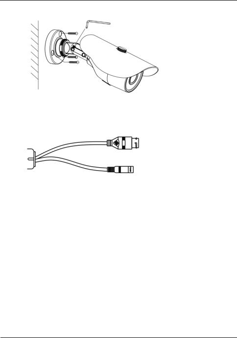
Step 2 Loosen the locking screw with L-Hex Wrench and rotate the camera, then attach the camera to the surface, as shown in Figure 3-4.
12 |
Issue V1.0 (2018-05-11) |
High-Resolution IR Camera |
|
User Manual |
Bullet camera |
Figure 3-4 Installing camera
Step 3 Connect the Power and video cable, as shown in Figure 3-5.
Figure 3-5 Connecting cable
Step 4 Loosen the locking screw with L-Hex Wrench, rotate the camera to adjust the position and image so that the camera faces the monitored area, then tighten the locking screw, as shown in Figure 3-6.
To rotate the part 1 of the camera for 360°, loosen rotation lock. To rotate the part 2 of the camera for180°, loosen screw 1.
To rotate the part 3 of the camera for 360°, loosen screw 2.
Issue V1.0 (2018-05-11) |
13 |

|
High-Resolution IR Camera |
Bullet camera |
User Manual |
Figure 3-6 Adjusting monitored area
----End
14 |
Issue V1.0 (2018-05-11) |

High-Resolution IR Camera |
|
User Manual |
Web Operation |
4 Web Operation
4.1 Quick start
4.1.1 Login and Logout
You must use Internet Explorer 7, and more to access the web management system; otherwise, some functions may be unavailable.
Login
Step 1 Open Internet Explorer, enter the IP address of the IP camera (default value: 192.168.1.64) in the address box, and press Enter.
The login page is displayed, as shown in Figure 4-1.
Figure 4-1 Login page
Step 2 Enter the user name, and password.
Issue V1.0 (2018-05-11) |
15 |
|
High-Resolution IR Camera |
Web Operation |
User Manual |
The default user name is admin. The default password is admin.
Change the password to ensure system security.
You can change the system display language on the login page.
Step 3 Click .
.
The main page is displayed.
----End
Logout
To log out of the system, click  in the upper right corner of the main page. The login page is displayed after you log out of the system.
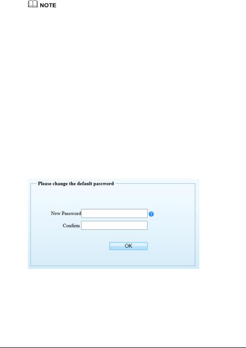
4.1.2 Changing the Password
Description
The change password page will be displayed as shown in Figure 4-2, when you login the system for the first time.
Figure 4-2 Change the default password page
Or click  to change the password for login the system, as show in Figure 4-3.
16 |
Issue V1.0 (2018-05-11) |

High-Resolution IR Camera |
|
User Manual |
Web Operation |
Figure 4-3 Change the password page
Step 1 |
Enter the old password, new password, and confirmation password. |
Step 2 |
Click OK. |
|
If the message "Change password success" is displayed, the password is successfully |
|
changed. If the password fails to be changed, the cause is displayed. (For example, the |
|
new password length couldn’t be less than eight.) |
Step 3 |
Click OK. |
|
The login page is displayed. |
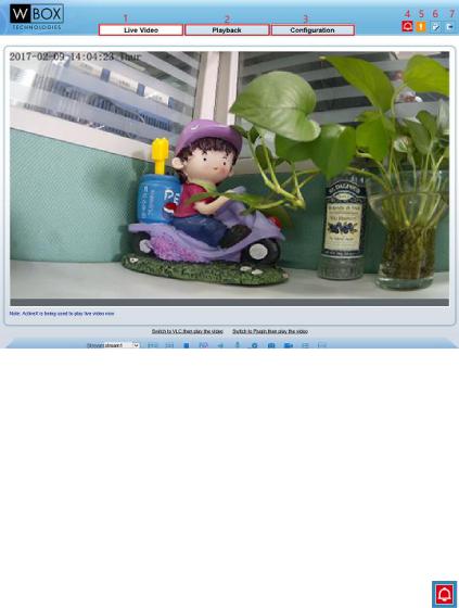
4.1.3 Main Page Layout
On the main page, you can view real-time videos, receive alarm and fault notifications, set parameters, change the password, and log out of the system. Figure 4-4 shows the main page layout. Table 4-1 describes the elements on the main page.
Issue V1.0 (2018-05-11) |
17 |
|
High-Resolution IR Camera |
Web Operation |
User Manual |
Figure 4-4 Main page layout
Table 4-1 Elements on the main page
|
No. |
Element |
Description |
|
|
|
|
|
1 |
Real-time video |
Real-time videos are played in this area. You can also set |
|
|
area |
sensor parameters. |
|
|
|
|
|
2 |
Playback |
You can query the playback videos in this area. |
|
|
|
NOTE |
|
|
|
Only when the SD card or NAS have videos that you can |
|
|
|
query the playback videos. |
|
|
|
|
|
3 |
Device |
You can choose a menu to set device parameters, |
|
|
configuration |
including the device information, audio and video |
|
|
|
streams, alarm setting, and privacy mask function. |
|
|
|
|
|
4 |
Alarm icon |
|
|
|
|
When the device generates an alarm, the alarm icon |
|
|
|
is displayed. You can click the icon to view the alarm |
|
|
|
information. |
|
|
|
NOTE |
|
|
|
When the device accepts an alarm signal, the alarm icon will |
|
|
|
display within 10s in the web management system. |
|
|
|
|
|
|
|
|
18 |
|
|
Issue V1.0 (2018-05-11) |
High-Resolution IR Camera |
|
|
||
User Manual |
|
|
Web Operation |
|
|
|
|
|
|
|
5 |
Fault icon |
When the device encounters an exception, the fault icon |
|
|
|
|
is displayed. |
|
|
|
|
You can click the icon to view the fault information. |
|
|
|
|
|
|
|
6 |
Change password |
|
|
|
|
|
You can click |
to change the password. |
|
|
|
|
|
|
7 |
Sign Out |
|
|
|
|
|
You can click |
to return to the login page. |
|
|
|
|
|
----End
4.2 Browsing Real-Time Videos
You can browse real-time videos in the web management system.
Preparation
You will be prompted with a message ”download and install the new plugin” as shown in Figure 4-5 when you log in to the web management system for the first time:
Figure 4-5 Download the plug-ins page
Step 1 Click “ download and install the new plugin”, download and setup the plug-ins and the install the plugin following the prompt.
Step 2 Reopen the browser after installing.
If the repair tips displayed when installing the control , please ignore the prompt, and continue the installation.
Issue V1.0 (2018-05-11) |
19 |

|
High-Resolution IR Camera |
Web Operation |
User Manual |
----End |
|
Description
To browse real-time videos, click Live Video. The Live Video page is displayed, as shown in Figure 4-6.
Figure 4-6 Live Video page
On the Live Video page, you can perform the following operations:
Click  to stop playing a video.
Click  to play a video.
Double-click in the video area to enter the full-screen mode, and double-click again to exit.
Switch among preset streams 1, 2, and 3. For details about how to configure streams, see 
Setting Video and Audio Stream Parameters.
Click  to snapshot and save the photos.
20 |
Issue V1.0 (2018-05-11) |

High-Resolution IR Camera |
|
User Manual |
Web Operation |
Configure the sensor.
You can right-click in the video area. A shortcut menu is displayed and allows you to enter the full-screen mode, set sensor parameters, zoom in or out, and return to the default view.
To set sensor parameters, click  to open the Sensor Setting page. On the Sensor Setting page, you can adjust the time segment, image, scene, exposure, white balance, focus setting, Iris setting, white balance, and noise filter as prompted.
4.3Configuring the Device
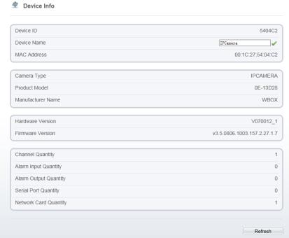
4.3.1 Configuring the Device Information
Description
The device information includes:
Device ID, name, type, model, and MAC address.
Hardware and software versions.
Number of video channels, number of alarm input channels, number of alarm output channels, and number of serial ports.
You can modify the device name. All other parameters can only be viewed.
When the device is upgraded, the device information is updated automatically.
Procedure
Step 1 Click Configuration > Device Info.
The Device Info page is displayed, as shown in Figure 4-7.
Issue V1.0 (2018-05-11) |
21 |
|
High-Resolution IR Camera |
Web Operation |
User Manual |
Figure 4-7 Device Info page
Step 2 View the device information, set the device ID and name according to Table 4-2. Table 4-2 Device parameters
|
Parameter |
|
|
Description |
|
|
Setting |
|
|
|
Device ID |
|
|
Unique device identifier used by the |
|
|
[Setting method] |
||
|
|
|
|
platform to distinguish the devices. |
|
|
These |
parameters |
|
|
|
|
|
|
|
|
|||
|
|
|
|
|
|
|
cannot be modified. |
||
|
|
|
|
|
|
|
|
||
|
Device Name |
|
|
Name of the device. |
|
|
[Setting method] |
||
|
|
|
|
NOTE |
|
|
Enter |
a |
value |
|
|
|
|
The device name cannot exceed 32 |
|
|
manually. |
|
|
|
|
|
|
|
|
|
|
|
|
|
|
|
|
bytes or 10 simplified characters; |
|
|
|
|
|
|
|
|
|
otherwise, the modification fails. |
|
|
|
|
|
|
|
|
|
|
|
|
|
||
|
MAC Address |
|
|
N/A |
|
|
[Setting method] |
||
|
|
|
|
|
|
|
These |
parameters |
|
|
Camera Type |
|
|
|
|
|
|||
|
|
|
|
|
|
cannot be modified. |
|||
|
|
|
|
|
|
|
|||
|
Product Model |
|
|
|
|
|
|||
|
|
|
|
|
|
|
|
|
|
|
|
|
|
|
|
|
|
|
|
|
Manufacturer Name |
|
|
|
|
|
|
|
|
|
|
|
|
|
|
|
|
|
|
|
|
|
|
|
|
|
|
|
|
22 |
|
|
|
|
Issue V1.0 |
(2018-05-11) |
|||

High-Resolution IR Camera |
|
|
|||
User Manual |
|
|
Web Operation |
||
|
|
|
|
|
|
|
Parameter |
|
Description |
|
Setting |
|
Hardware Version |
|
|
|
|
|
|
|
|
|
|
|
Firmware Version |
|
|
|
|
|
|
|
|
|
|
|
Video Channel(s) |
|
|
|
|
|
|
|
|
|
|
|
Channel Quantity |
|
|
|
|
|
|
|
|
|
|
|
Alarm Input Quantity |
|
|
|
|
|
|
|
|
|
|
|
Alarm Output Quantity |
|
|
|
|
|
|
|
|
|
|
|
Serial Port Quantity |
|
|
|
|
|
|
|
|
|
|
|
Network card Quantity |
|
|
|
|
|
|
|
|
|
|
Step 3 |
Click |
. |
|
|
|
If the message "Apply success!" is displayed, click OK. The system saves the settings.
If the message "Apply failed!" is displayed, you must apply for the Parameter Configure permission from an administrator. For details, see 4.10.1
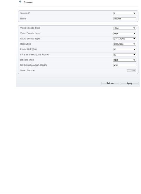
4.4Setting Video and Audio Stream Parameters
Procedure
Step 1 Click Configuration > Stream > Base Stream.
The Stream Configuration page is displayed, as shown in Figure 4-8.
Issue V1.0 (2018-05-11) |
23 |
|
High-Resolution IR Camera |
Web Operation |
User Manual |
Figure 4-8 Stream Configuration page
Step 2 Set the parameters according to Table 4-3.
Table 4-3 Stream configuration parameters
Parameter |
|
Description |
|
Setting |
|
|
Stream ID |
|
The device supports 3 streams. |
|
[Setting method] |
|
|
|
|
Streams 1 and 2 use the H.264 codec. |
|
Select a value from the |
||
|
|
|
|
drop-down list box. |
||
|
|
The maximum resolution can be set |
|
|
|
|
|
|
for streams 1. |
|
|
|
|
|
|
|
|
|
|
|
Name |
|
Stream name. |
|
[Setting method] |
|
|
|
|
NOTE |
|
Enter a value manually. |
||
|
|
The stream name is combined with |
|
The |
value |
cannot |
|
|
|
exceed 32 bytes. |
|
||
|
|
Chinese character, number, character and |
|
|
||
|
|
|
|
|
|
|
|
|
underline. |
|
[Default value] |
|
|
|
|
|
|
stream1 |
|
|
|
|
|
|
|
|
|
24 |
Issue V1.0 (2018-05-11) |

High-Resolution IR Camera |
|
|
|
|
|
|
|
|
|
|
|
User Manual |
|
|
|
Web Operation |
|
|
|
|
|
||
|
|
|
|
|
|
|
|
|
|
|
|
|
Parameter |
Description |
|
|
|
Setting |
|
|
|
|
|
|
Video Encode |
The video codec determines the image |
[Setting method] |
|
|||||||
|
Type |
quality and network bandwidth required |
Select a value from the |
||||||||
|
|
by a video. Currently, the following |
drop-down list box. |
|
|||||||
|
|
codec standards are supported: |
[Default value] |
|
|
||||||
|
|
|
|
|
|
|
|
|
|||
|
|
MJPEG |
|
|
|
H.264 |
|
|
|
|
|
|
|
MJPEG is a standard intra-frame |
NOTE |
|
|
|
|
||||
|
|
compression |
codec. |
The |
compressed |
The H.264 High Profile |
|||||
|
|
image quality is good. No mosaic is |
codec |
means |
high |
||||||
|
|
displayed on motion images. MJPEG |
requirements |
on |
the |
||||||
|
|
does |
not |
support |
proportional |
hardware. |
If |
the |
hard |
||
|
|
compression and requires large storage |
decoding |
capability is |
|||||||
|
|
space. |
Recording |
and |
network |
low, use |
H.264 |
Main |
|||
|
|
transmission occupy large hard disk |
Profile |
or |
H.264 |
Base |
|||||
|
|
space and bandwidth. MJPEG is not |
Profile. |
|
|
|
|
||||
|
|
applicable to continuous recording for a |
|
|
|
|
|
||||
|
|
long period of time or network |
|
|
|
|
|
||||
|
|
transmission of videos. It can be used to |
|
|
|
|
|
||||
|
|
send alarm images. |
|
|
|
|
|
|
|
||
|
|
H.264 |
|
|
|
|
|
|
|
|
|
H.264 consists of H.264 Base Profile,
H.264 Main Profile, and H.264 High profile. The performance of H.264 High Profile is higher than that of H.264 Main Profile, and the performance of H.264 Main Profile is higher than that of H.264 Base Profile. If a hardware decoding device is used, select the appropriate codec based on the decoding performance of the device.
|
H.264 High Profile has the highest |
|
|||
|
requirements |
on |
the |
hardware |
|
|
performance, and H.264 Base Profile |
|
|||
|
has the lowest requirements on the |
|
|||
|
hardware performance. |
|
|
|
|
|
H.265 |
|
|
|
|
|
H.265 is the new video encoding |
|
|||
|
standard ,it's the improvement standard |
|
|||
|
from H.264. |
H.265 |
improves the |
|
|
|
streams, encoding quality and algorithm |
|
|||
|
complexity to make configuration as |
|
|||
|
optimization. |
|
|
|
|
|
|
|
|||
Audio Encode |
The following audio codec standards are |
[Setting method] |
|||
Type |
supported: |
|
|
|
Select a value from the |
|
|
|
|
|
|
Issue V1.0 (2018-05-11) |
25 |
|
|
|
|
High-Resolution IR Camera |
|
Web Operation |
|
|
|
User Manual |
|
|
|
|
|
|
|
|
Parameter |
Description |
|
Setting |
|
|
|
|
G711_ULAW: mainly used in North |
|
drop-down list box. |
|
|
|
America and Japan. |
|
|
|
|
|
G711_ALAW: mainly used in Europe |
|
|
|
|
|
and other areas. |
|
|
|
|
|
RAW_PCM: codec of the original |
|
|
|
|
|
audio data. This codec is often used |
|
|
|
|
|
for platform data. |
|
|
|
|
|
|
|
|
|
Resolution |
A higher resolution means better image |
|
[Setting method] |
|
|
|
|
quality. |
|
Select a value from the |
|
|
|
|
|
|
|
|
|
NOTE |
|
drop-down list box. |
|
|
|
IP cameras support the different |
|
|
|
|
|
resolutions based on the model. |
|
|
|
|
|
|
|
|
|
Frame |
|
The frame rate is used to measure |
|
[Setting method] |
|
Rate(fps) |
|
displayed frames. A higher frame rate |
|
Select a value from the |
|
|
|
|
|
|
|
|
|
means smoother videos. A video whose |
|
drop-down list box. |
|
|
|
frame rate is higher than 22.5 f/s is |
|
|
|
|
|
considered as smooth by human eyes. |
|
|
|
|
|
Frame rates for different frequencies are |
|
|
|
|
|
as follows: |
|
|
|
|
|
50 Hz: 1–25 f/s |
|
|
|
|
|
60 Hz: 1–30 f/s |
|
|
|
|
|
NOTE |
|
|
|
|
|
The frequency is set on the Device |
|
|
|
|
|
Configuration > Camera page. The |
|
|
|
|
|
biggest MJPEG coding format frame rate |
|
|
|
|
|
is 12 frames per second. |
|
|
|
|
|
|
|
|
|
I |
Frame |
I frames do not require other frames to |
|
[Setting method] |
|
Interval(Unit:Fr |
decode. |
|
Select a value from the |
|
|
|
|
|
|
|
|
ame) |
|
A smaller I frame interval means better |
|
drop-down list box. |
|
|
|
video quality but higher bandwidth. |
|
|
|
|
|
|
|
|
|
Bit Rate Type |
The bit rate is the number of bits |
|
[Setting method] |
|
|
|
|
transmitted per unit of time. |
|
Select a value from the |
|
|
|
|
|
|
|
|
|
The following bit rate types are |
|
drop-down list box. |
|
|
|
supported: |
|
|
|
|
|
Constant bit rate (CBR) |
|
|
|
|
|
The compression speed is fast; however, |
|
|
|
|
|
improper bit rate may cause vague |
|
|
|
|
|
motion images. |
|
|
|
|
|
Variable bit rate (VBR) |
|
|
|
|
|
|
|
|
26 |
|
|
|
|
Issue V1.0 (2018-05-11) |
 Loading...