

Page 1
SSL E-Channel & G-Channel User Manual
1
SSL 4000 Collection
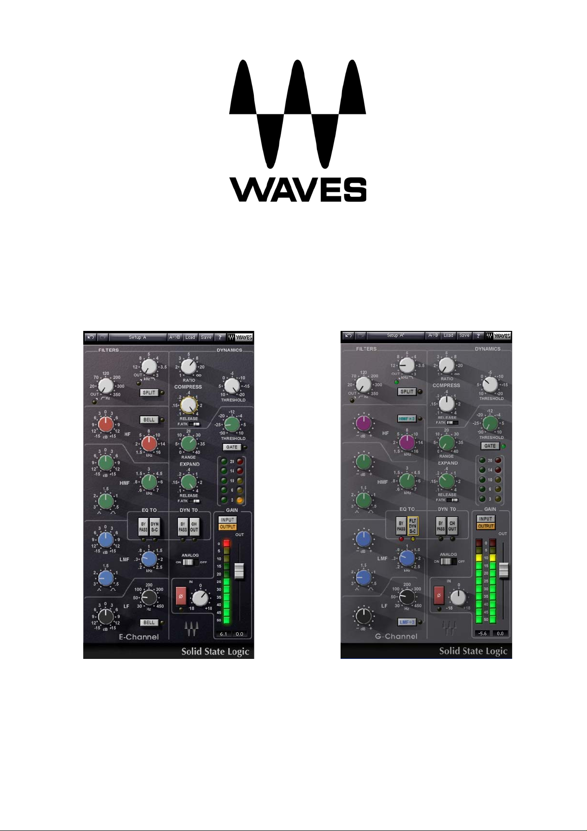
SSL 4000 E-Channel SSL 4000 G-Channel
Page 2

SSL E-Channel & G-Channel User Manual
2
Table of Contents
1. INTRODUCTION ............................................................................................................... 3
2. PRODUCT OVERVIEW....................................................................................................... 4
SSL E-Channel..................................................................................................................4
SSL G-Channel .................................................................................................................4
Dynamics Section..............................................................................................................4
Equalizer Section ..............................................................................................................5
SSL Channel Routing Diagram ............................................................................................6
3. CONTROLS AND INTERFACE............................................................................................. 8
DYNAMICS SECTION CONTROLS ....................................................................................................9
Compressor......................................................................................................................9
Expander/Gate .................................................................................................................9
Dyn To ............................................................................................................................9
E-CHANNEL EQ SECTION CONTROLS............................................................................................10
Low and High Pass Filters.................................................................................................10
High Frequency EQ Section ..............................................................................................10
High Medium Frequency EQ Section ..................................................................................10
Low Medium Frequency EQ Section ...................................................................................10
Low Frequency EQ Section ...............................................................................................10
G-CHANNEL EQ SECTION CONTROLS ...........................................................................................11
Low and High Pass Filters.................................................................................................11
High Frequency EQ Section ..............................................................................................11
High Medium Frequency EQ Section ..................................................................................11
Low Medium Frequency EQ Section ...................................................................................11
Low Frequency EQ Section ...............................................................................................11
EQ To ............................................................................................................................12
MASTER SECTION...................................................................................................................12
4. THE WAVES SYSTEM BAR............................................................................................... 13
Page 3

SSL E-Channel & G-Channel User Manual
3
1. Introduction
The unique sound of Solid State Logic 4000 Series analogue mixing consoles is sought after
worldwide. Engineers of pop and rock music, broadcast transmissions and television post-production
value the SSL 4000’s flexible dynamics chain as much as the trademark SSL “punchy” sound. Waves
and SSL engineers have worked together for over a year to recreate the sound characteristics of the
classic SSL 4000 Series E and Series G consoles. Now, those who “mix in the box” can achieve the
sound they thought they’d lost when they moved to the digital world.
The SL4000 console was the first mixing desk to incorporate dynamics processing into every channel,
as well as a master bus compressor in the console’s center section. The ability to 'patch' into the
SL4000's master bus compressor and to control its sidechain from an internal sub-mix allowed sound
engineers to discover unique, history-making applications of this console technology. Whether used
to record instruments such as piano and drums or for final mixing, these innovative console sections master bus compressor, EQ and dynamics - opened up a new world of opportunities. For years,
workstation users have sought this unusual flexibility and signature sound. But conventional
dynamics and EQ plug-ins couldn’t produce the unique SSL color.
The Waves SSL 4000 Collection is the result of a partnership between Waves Audio and Solid State
Logic. These processors faithfully recreate the same EQ and dynamics characteristics which made
legendary the SL4000 consoles. Plus, the interface accurately reflects the classic SSL console.
Couple all of this with state-of-the art Waves software and you suddenly find yourself working with
the same tools that have provided countless hit mixes for the world's best audio engineers.
The Waves SSL 4000 Collection consists of four main components:
E-Channel
G-Channel
G-Master Bus Compressor
G-Equalizer
Page 4

SSL E-Channel & G-Channel User Manual
4
2. Product Overview
SSL E-Channel
The Waves SSL E-Channel is modeled after the SL4000 E Series console, combining the dynamics
section of the SL4000 channel strip with the “Black Knob” 242 EQ. The only noticeable change from
the hardware original is that the EQ and Dynamics sections are side-by-side rather than inline, to
better conform to computer screens.
SSL G-Channel
The Waves SSL G-Channel is modeled after the SL4000 G Series console, combining the dynamics
section of the SL4000 channel strip with the 383 G EQ. The only noticeable change from the
hardware original is that the EQ and Dynamics sections are side-by-side rather than inline, to better
conform to computer screens.
The E-Channel and G-Channel have latency of one sample.
Dynamics Section
The dynamics section consists of a soft-knee compressor/limiter and an expander/gate. Dynamics
can be switched to pre-equalizer (default) or post-equalizer (CH OUT.)
Although the same gain change circuitry is used for both the compressor/limiter and the
expander/gate, two dedicated level indicators illustrate activity for each device. Automatic gain
make-up, calculated from the Ratio and Threshold settings, is applied by the compressor to maintain
a steady output level. The default compressor attack time is program sensitive, responding to the
audio material’s wavefront.
The dynamics section’s threshold circuitry uses variable hysteresis, which allows the signal to decay
below its opening level. (Hysteresis is the lag between making a change in input, such as increasing
or decreasing power, and the response or effect of that change. Thus, the threshold’s variable
hysteresis circuitry allows for program-dependent dynamic processing.)
Page 5

SSL E-Channel & G-Channel User Manual
5
Equalizer Section
The equalizer is a four-band device which can be routed to the processor’s output or to the dynamics
section’s sidechain. Q can be adjusted in the LMF and HMF ranges. At the top of the section is the
High Pass (18 dB/octave) filter and the Low Pass (12 dB/octave) filter. Normally, low pass and
high pass filters follow the same path as the entire EQ section. However, when Split is selected, the
low pass and high pass filters are placed before the dynamics processors in the chain. The equalizer
can be switched into the dynamics sidechain to afford simple de-essing and other frequencycontrolled dynamics processing by selecting Dyn S-C at the foot of the section. In the E-Channel LF
and HF shelves can be reshaped to bell curves by pressing Bell. The Q of the LF and HF bells are
calculated based on frequency settings and are not user-definable. In the G-Channel LF and HF are
fixed shelves, LMF/3 divides the LMF frequency by 3, while HMFx3 multiplies the HMF frequency by
three.
Page 6

SSL E-Channel & G-Channel User Manual
6
SSL Channel Routing Diagram
Page 7

SSL E-Channel & G-Channel User Manual
7
Page 8

SSL E-Channel & G-Channel User Manual
8
3. Controls and Interface
Page 9

SSL E-Channel & G-Channel User Manual
9
Dynamics Section Controls
Compressor (white knobs)
The compressor’s Ratio/Slope can be set from 1 to infinity (limiter).
The Threshold is variably adjustable from +10 dB to -20 dB.
When the Attack time switch is set to Slow (F.ATK off) attack time is auto-sensing and
program dependent. Fast setting (F.ATK) attack time is 1 ms.
Release time is adjustable from 0.1 to 4 seconds.
Expander/Gate (green knobs)
The expander’s Threshold is variable from -30 dB to +10 dB.
Range is variable from 0 – 40 dB.
When the Attack time switch is set to Slow (F.ATK off) attack time is auto-sensing and
program dependent. Fast setting (F.ATK) attack time is 1 ms.
Release time is adjustable from 0.1 sec to 4 seconds.
The Gate switch toggles the section from an expander (default mode) into a gate.
Dyn To
Bypass bypasses the entire dynamics section. Note that selecting Bypass does not result in a
flat signal, but rather one which mimics the flat response of the SSL channel strip hardware.
Ch Out moves the dynamics to the output of the E-Channel, making it post-EQ.
Page 10

SSL E-Channel & G-Channel User Manual
10
E-Channel EQ Section Controls
Low and High Pass Filters (white knobs)
Low Pass: 12 dB/octave, 3 KHz – 22 KHz (-3 dB point).
High Pass: 18 dB/octave, 16 Hz – 350 Hz (-3 dB point).
Turning the knob completely to the left bypasses the filter.
When Split is selected, the low pass and high pass filters are placed before the dynamics
processors in the chain.
High Frequency EQ Section (red knobs)
Range 1.5 kHz – 16 kHz.
Gain range is ±18 dB for bell shape, ±16.5 dB for shelving.
Selecting Bell changes the HF EQ from shelf to bell shape.
High Medium Frequency EQ Section (green knobs)
Range 600 Hz – 7 kHz
Q is continuously adjustable from 0.1 to 3.5.
Gain varies from ±18 dB when Q is set at 3.5, to ±15 dB when Q is set at 0.1.
Low Medium Frequency EQ Section (blue knobs)
Range 200 Hz – 2.5 kHz
Q is continuously adjustable from 0.1 to 3.5
Gain varies from ±18 dB when Q is set at 3.5 to ±15 dB when Q is set at 0.1.
Low Frequency EQ Section (black knobs)
Range 30 Hz – 450 Hz
Gain range ±16.5 dB shelving, ±18 dB, bell shape
Page 11

SSL E-Channel & G-Channel User Manual
11
G-Channel EQ Section Controls
Low and High Pass Filters (white knobs)
Low Pass: 12 dB/octave, 3 KHz – 22 KHz (-3 dB point).
High Pass: 18 dB/octave, 16 Hz – 350 Hz (-3 dB point).
Turning the knob completely to the left bypasses the filter.
When Split is selected, the low pass and high pass filters are placed before the dynamics
processors in the chain.
High Frequency EQ Section (Magenta knobs)
Range 1.5 kHz – 16 kHz.
Gain range is ±17 dB shelving.
High Medium Frequency EQ Section (green knobs)
Range 600 Hz – 7 kHz.
Q is continuously adjustable from 0.1 to 3.5.
Gain varies from ±20 dB when Q is set at 3.5 to ±15 dB when Q is set at 0.1.
HMFx3 multiplies the frequency by 3.
Low Medium Frequency EQ Section (blue knobs)
Range 200 Hz – 2.5 kHz.
Q is continuously adjustable from 0.1 to 3.5.
Gain varies from ±20 dB when Q is set at 3.5 to ±15 dB when Q is set at 0.1.
LMF/3 divides the frequency by 3.
Low Frequency EQ Section (black knobs)
Range 30 Hz – 450 Hz.
Gain range ±17 dB, shelving.
Page 12

SSL E-Channel & G-Channel User Manual
12
EQ To
Bypass bypasses the EQ section. Note that selecting Bypass does not result in a flat signal ,
but rather one which mimics the flat response of the SSL channel strip hardware.
Dyn S-C- E-Channel switches the filters and eq into the dynamics sidechain, enabling simple
de-essing, etc.
FLT Dyn S-C- G-Channel- switches the filters into the dynamics sidechain.
Master Section
Level Indicator expresses levels in dBFS, although all parameters are expressed as dBu.
Input and Output switches above the meter allow you to toggle the level indicator between
input and output.
Input Trim enables you to trim the input to the channel by ± 18db. The plug-in is aligned so
that -18 dBFS = 0dbu.
Output fader controls the output level of the processor.
Analogue On/Off
Switching off Analogue disables analogue emulation.
Phase Reverse (Ø) reverses the phase of the input signal.
Page 13

SSL E-Channel & G-Channel User Manual
13
4. The Waves System Bar
All Waves plug-ins share a common feature, the Waves System Bar, which takes care of most
administrative functions you will encounter while working with Waves plug-ins. Since the Waves
System Bar is the same on practically all Waves plug-ins, you will always know how to file, compare,
load and copy the parameters of a Waves plug-in, even if you have never before worked with that
particular processor. The following commands are common to all Waves plug-ins:
Undo undoes the last performed action.
Redo redoes the last undone action. There are 6 levels of undo and redo.
Setup A/B toggles between two sets of parameters within the same processor – useful when
comparing different parameter settings in order to achieve optimal results.
Copy A->B copies the current settings to the second setup register.
Save used for saving presets in the Waves file format (.xps)
There are two options for saving:
Save to new file: creates a new .xps file wherein multiple presets can be saved.
Save into preset menu: saves the preset into the default list of the plug-in.
Load allows recalling presets from files.
Once a file is selected, its first preset will load and become active. Other presets in the file will be
listed under the preset’s name in the Load menu.
You can also load factory presets and user presets (saved using Save into preset menu.)
Pressing the ? button will open the manual for the plug-in you are using.
 Loading...